CPAA under NFM-P management
General information
The 7701 CPAA and vCPAA are managed by the NFM-P like any other NE. Management procedures such as timing synchronization, polling, deployments, and NE resynchronization, are similar to procedures for other SR OS devices. See the NSP NFM-P Classic Management User Guide for information about general device management functions. The scope of commands on the CPAA is much smaller than those of any other SR-based router.
The CPAA can be managed in-band or out-of-band under the NFM-P. Out-of-band management is performed through the management port of the CPAA. For in-band management, the network must be able to route traffic to the CPAA using the system IP address of the CPAA. In-band management is possible only if the port on the router that is physically connected to the CPAA is in network mode.
Operating system configuration
The CPAA OS is based on the 7750 SR OS. The CLI configurations and management for the CPAA are a subset of the 7750 SR.
CPAA alarm support
All alarms supported in CPAA Release 8.0 are also supported in CPAA Release 9.0 and CPAA Release 10.0.
The 7701 CPAA hardware rev.2 and vCPAA do not support power supply alarms or power failure alarms. The CPAA OS has no visibility of the power supply, and cannot detect power interruptions.
Out-of-band management
The CPAM and CPAA use two TCP channels: an SNMP/UDP channel for event notifications, and a CLI over Telnet/SSH2 session for general communication.
The TCP channels can be configured as out-of-band so that the events and control data are carried over a separate management network. In such a case, the CPAA management address is different from the system IP address.
IGP administrative domains
An IGP administrative domain is a routed network that contains, for each OSPF and IS-IS, one backbone. An IGP administrative domain can have both an OSPF and IS-IS backbone at the same time. For OSPF, it is assumed that there cannot be multiple instances of any area within an admin domain. An IGP administrative domain is uniquely identified by a domain number and name. A CPAA which is configured with an IGP role is assigned to each IGP administrative domain.
BGP AS administrative domains
An administrative domain which represents the standard BGP AS, confederation AS, or sub-AS. A BGP confederation AS administrative domain contains other BGP sub-ASs. A BGP AS is identified by a BGP AS number, which should be identical to the network-configured BGP AS, a BGP AS name, and BGP AS type. Each BGP AS administrative domain is associated with only one IGP administrative domain. An IGP administrative domain can be associated with several BGP AS administrative domains. A CPAA which is configured with a BGP role must be assigned to each BGP AS administrative domain. Each CPAA can be assigned to only one BGP AS administrative domain.
Routing protocols
When interacting with OSPF routing protocols, the CPAA establishes normal OSPF neighborships, but prevents other routers from routing through it by advertising its own OSPF links with a metric of 65535. The CPAA only advertises its own links, so in addition to the metric, traffic cannot be routed through the CPAA. The CPAA system address and its interfaces will appear in the OSPF routing table of the other nodes in the network.
When interacting with BGP routing protocols, the CPAA estabilishes normal BGP peerings, but does not advertise any BGP prefixes.
Routing domains
A CPAA is connected to the IGP routing plane in the same way an IGP router—OSPF or IS-IS—is connected to its neighbors.
A CPAA can be connected to several OSPF routing areas, and to both IS-IS L2 and L1 routing domains. In addition, a CPAA can have multiple interfaces to a routing domain. There can be only one active interface for any routing domain. A CPAA can be connected to an OSPF and an IS-IS network at the same time.
Note: All of the CPAAs must be connected to routing domains in the same IGP administrative domain.
The CPAM supports OSPFv2.
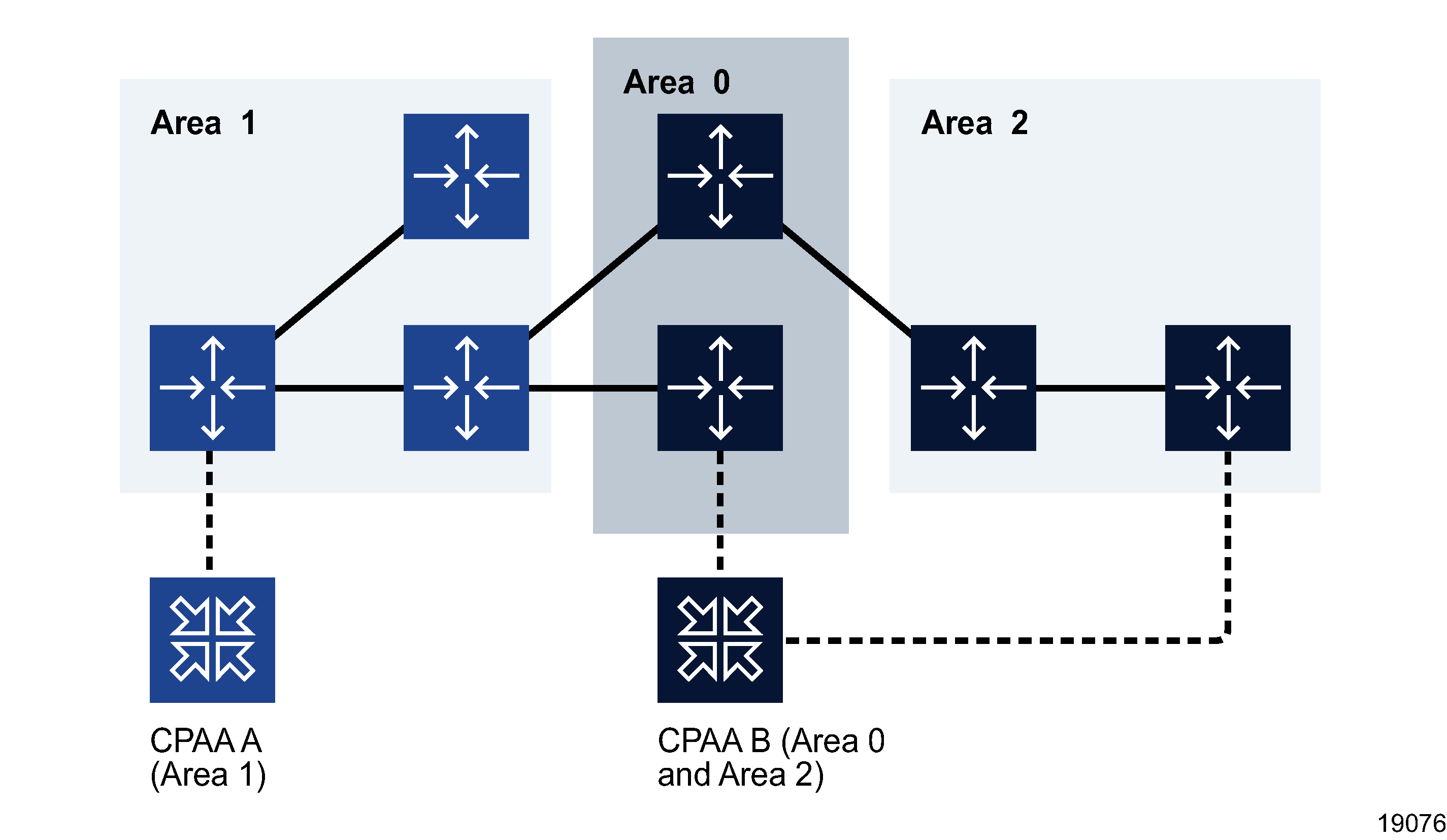
The following figure shows an OSPF network with three areas: 0 (backbone), 1, and 2. CPAA A is responsible for Area 1. CPAA B is responsible for Areas 0 and 2.
Figure 1-1: CPAAs connected to an OSPF network

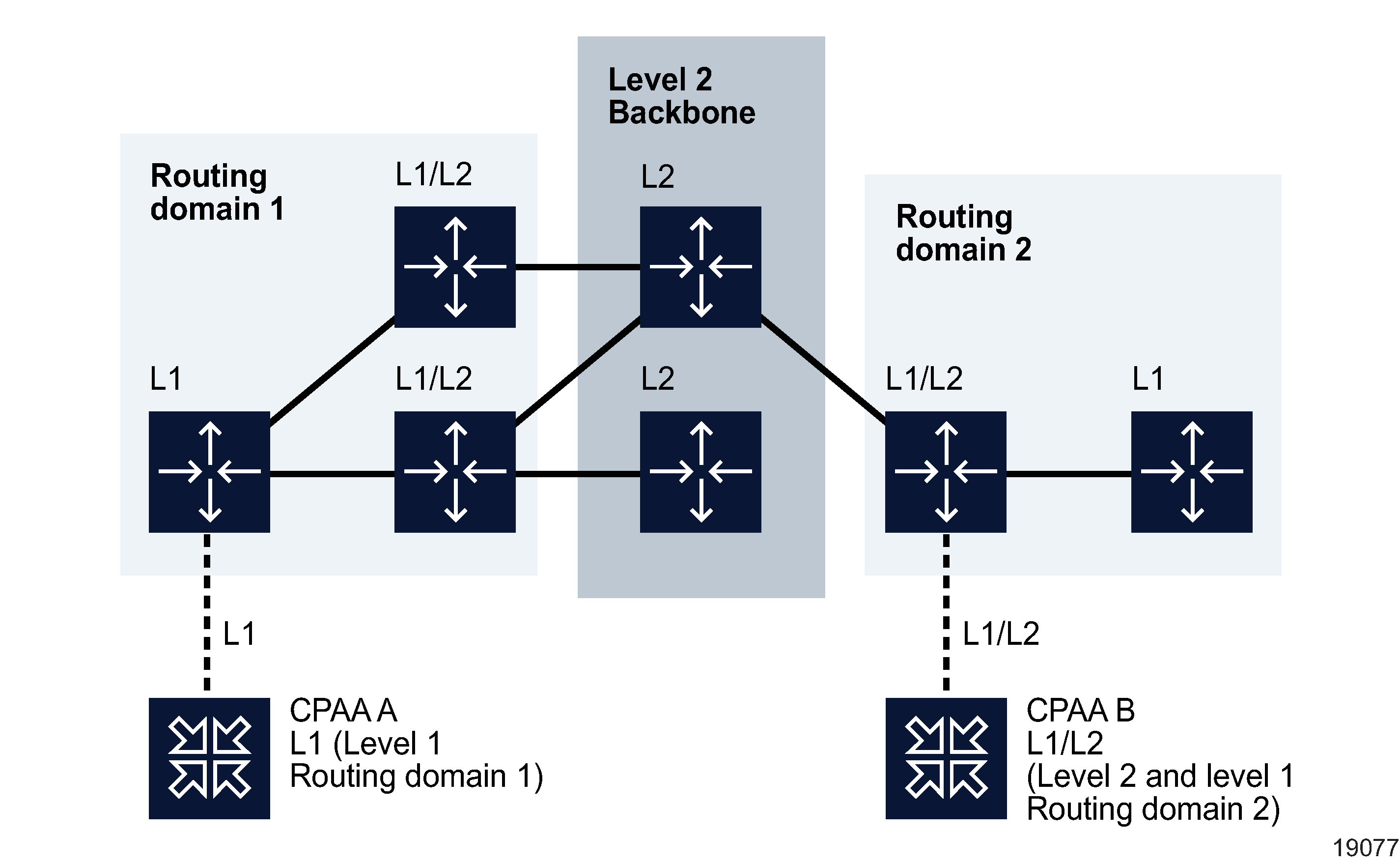
The following figure shows an IS-IS network with two level-1 routing domains and a level-2 backbone. CPAA A is responsible for level-1 Routing domain 1 over the L1 link. CPAA B is responsible for the level-2 backbone and the level-1 Routing domain 2 over the L1/L2 link. L2 routers must not explicitly belong to an routing domain.
Figure 1-2: CPAAs connected to an IS-IS network

CPAA network connections
The number of CPAAs deployed in the network is determined by the number of IGP areas, the router count per area, the backhaul strategy, the protocols deployed, the amount of monitoring required, and the BGP architecture (confederation, mesh or route reflector). Scalability limits can be found in the NSP Planning Guide. To determine the number of CPAAs required for a particular deployment, contact your Nokia representative.
For OSPF, the CPAA allows the configuration of multiple interfaces for an OSPF area. Of these interfaces, there can be multiple physical IGP interfaces— interfaces that are bound to a port— but only one logical interface, such as the system interface. No other loopback interface is allowed. The NFM-P also enforces this restriction for 7750 SR routing configuration. To prevent data traffic from passing through it, the CPAA does not send type 3, 4, or 5 LSP information to its neighbors. No LSP information is sent from one area to another.
For IS-IS, there is only one active L1 link and one active L2 link from a CPAA. This restriction guarantees that there is only one link to each L1 IS-IS routing domain, which could use multiple area IDs. More than one L1 link can be configured, but all of the links must use the same area ID. All L1 links can be in an Adjacency Up state, which is equivalent to FULL state in OSPF, but the CPAA sends the LSP of the active link only.
Note: Because only one active IGP link to a routing area or level can exist and the CPAA does not act as an ABR router, traffic that is not destined to it should never be sent to the CPAA. This data can still reach the CPAA in some cases.
To ensure that all of the traffic that is not destined to the route listener is dropped, it is strongly recommended that you create a routing policy for all of the routers connected to the CPAA.
Multiple IGP interfaces can share the physical interface where each protocol interface occupies a VLAN ID. If the neighbors of the CPAA are not physically attached to the CPAA, IGP links can be carried over VLL Epipes. The following figure shows two remote areas (A and B) that are connected to the CPAA over VLL Epipes.
Figure 1-3: CPAAs connected to routing areas through VLL Epipes

CPAA link redundancy
A CPAA can have multiple IGP interfaces to one routing area. The CPAA advertises the LSA/LSP for only the active link of the redundant pair.
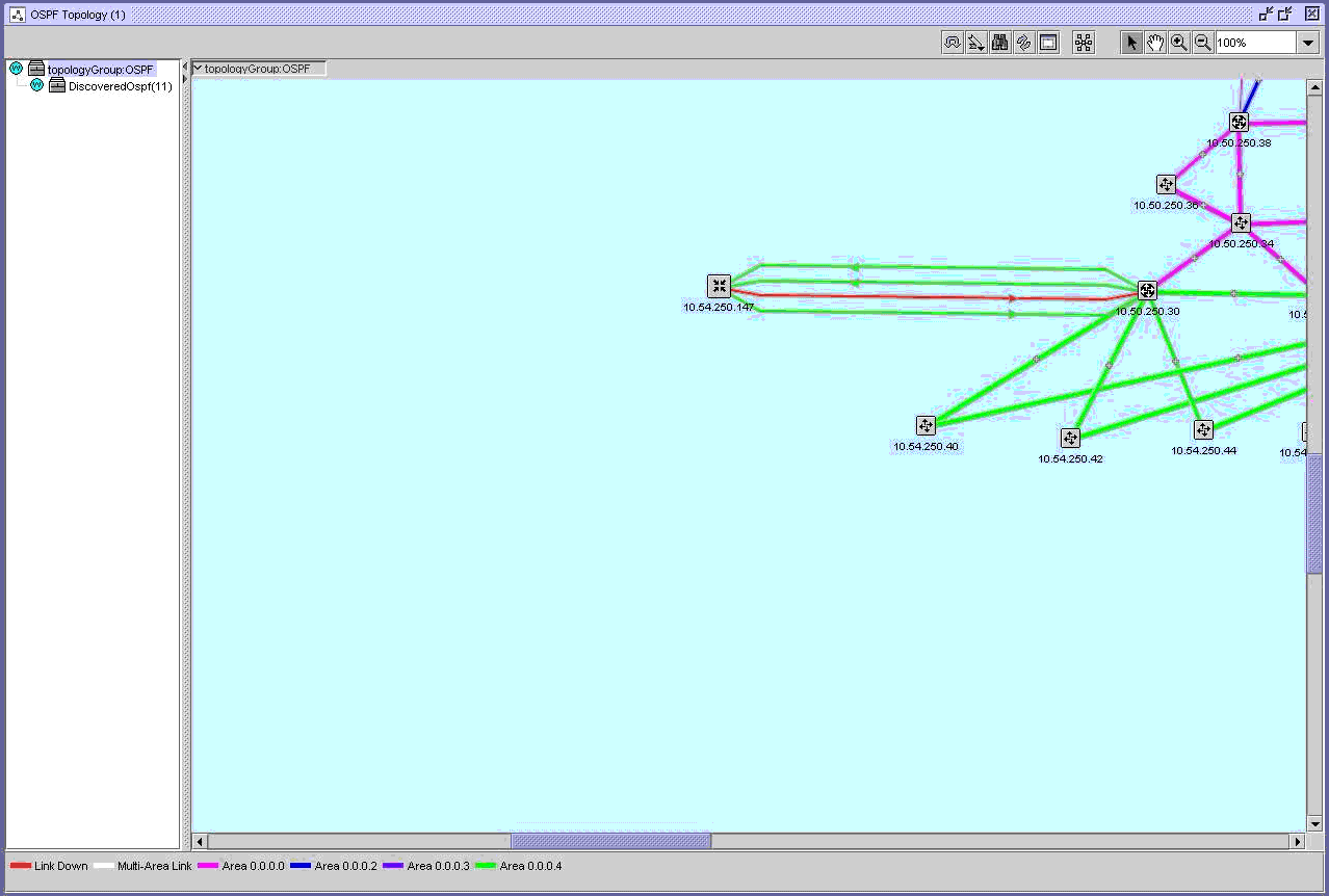
For example, a router and a CPAA are connected through two interfaces, both in the same OSPF or IS-IS area. Three unidirectional links—two links from the router and one link from the CPAA—appear on the topology map because the CPAA advertises only the active link. The standby link from the CPAA is not displayed on the topology map. The following sequence of events occurs:
-
a fault occurs and the active link A becomes operationally down
-
the standby link B becomes operationally up and becomes the active link B that is advertised by the CPAA
The CPAA informs the CPAM that the active link A (now a standby link) is deleted and a new active link B has been added. The following links appear on the topology map, as displayed in Figure 1-4, CPAA redundancy example :
See Chapter 18, Impact analysis for information about link colors and topology checkpoints.
Figure 1-4: CPAA redundancy example

© 2023 Nokia. Nokia Confidential Information
Use subject to agreed restrictions on disclosure and use.