| Equipment layout and clearances | |||
|
| GO | ||
Minimum clearances must be maintained between the cabinets and surrounding building parts/cabinet to accommodate the installation and maintenance of the base station.
The following constraints must be considered for cabinet clearances:
In line-ups where battery back-up cabinets may be needed, the footprint location must be ascertained ahead of time because batteries cannot be added easily to side-by-side cabinets when battery back-up cabinets are in the center of a line-up.
The battery cabinet must be installed adjacent to the power cabinet.
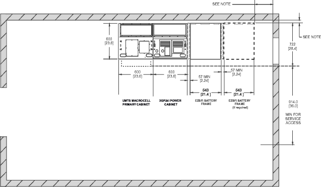
The following diagram shows the equipment layout for a typical new indoor Macrocell site.
Notes:
The cabinets may be placed with zero clearance to the rear wall.
The cabinets may be placed with zero clearance to the side wall, however some clearance is recommended.
Minimum space between the EZBFi frame and the adjacent cabinet or frame is 57 mm (2.24 in.) (if the edge of the template is cut at the dotted line).
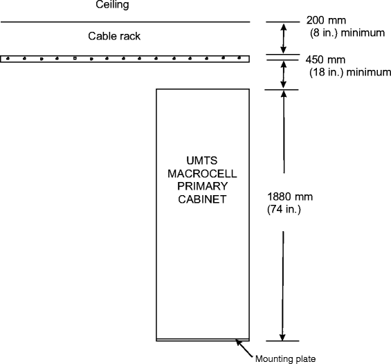
The following diagram shows the clearance requirements for the indoor UMTS Macrocell cabinet from the top of the cabinet to the cable rack and from the top of the cable rack to the ceiling.
This table below lists minimum clearances for indoor primary and power cabinets to an adjacent building or parts/cabinets.
|
Parameters for primary and power cabinets |
Minimum clearance |
|
Cabinet rear panel - wall |
0 |
|
Cabinet right/left side panel - wall (door fully opened) |
0 |
|
Above the cabinet |
650 mm (26 inches) |
|
In front of the cabinet (for installation and service access) |
914 mm (36 inches) |
|
Side adjacent to growth cabinet |
0 |
|
Top of cabinet - bottom of cable rack |
200 mm (8 inches) |
|
|
GO | ||
| © Alcatel-Lucent | |||