| Anchor hole requirements and footprints | |||
|
| GO | ||
This section provides instructions for preparing the cabinet anchor holes. Cabinet anchoring must meet local code requirements and take into consideration the earthquake zone at the installation site.
The UMTS Macrocell cabinets can be mounted on the following:
Concrete or raised floor.
Mounting plates are shipped with the Macrocell cabinet and serve as drilling templates and leveling plates. The mounting plate is placed under the cabinet during installation.
The following table provides anchoring specifications for seismic zones 0 through 4.
|
Cabinet |
Seismic zone(s) |
Anchor type |
Number of anchor holes |
Hole size (mm) |
Hole Depth (mm) |
|
UMTS primary cabinet/ 3GP24i power cabinet |
0, 1, 2 |
13 mm (1/2 in.) Dia. drop in |
4 |
16 mm (5/8 in.) |
50 mm (2 in.) |
|
3, 4 |
M12 x 125 mm |
4 |
18 mm (11/16 in.) |
100 mm front (4 in.) 75 mm rear (3 in.) | |
|
EZBFi battery frame |
0, 1, 2, 3 |
13 mm (1/2 in.) Dia. drop in |
4 (Marked “A”) |
16 mm (5/8 in.) |
50 mm (2 in.) |
|
4* |
13 mm (1/2 in.) Dia. drop in |
8 (Marked “A” and “B”) |
16 mm (5/8 in.) |
50 mm (2 in.) |
Important! If installing EZBFi in zone 4, a zone 4 Kit is required.
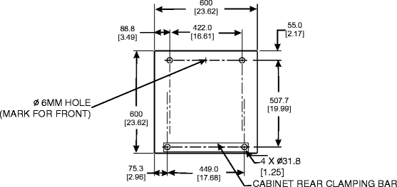
The following diagram shows the anchoring footprint for the UMTS primary and 3GP24i power cabinet.
The following diagram shows the anchor hole marking template for the EZBFi battery frame.
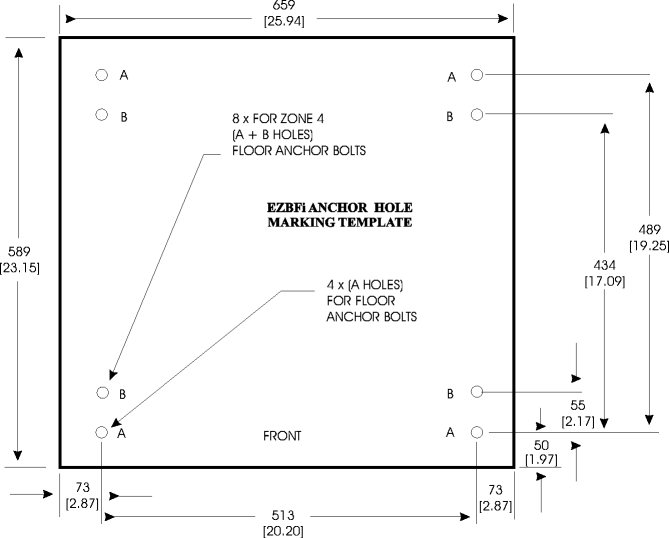
Important! The four holes identified as “A” are for Zone 0, 1, 2, and 3 installations. The eight holes identified as “A” and “B” are for Zone 4 installations.
|
|
GO | ||
| © Alcatel-Lucent | |||