Installation steps
Description
Rack mount
1 |
The Alcatel-Lucent 1850 TSS-5C can be installed in the following racks by use of a suitable installation bracket. |
2 |
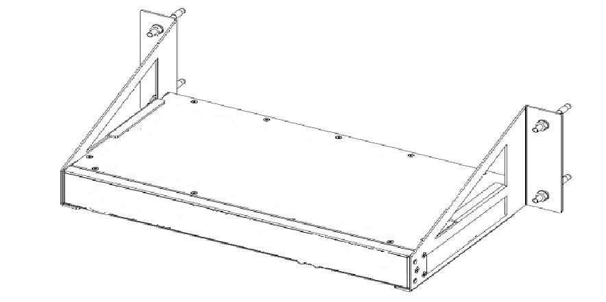
Select the appropriate brackets from the installation kit. A rack mounting bracket is displayed in Figure 2-3, Alcatel-Lucent 1850 TSS-5C with rack mounting bracket. Figure 2-3: Alcatel-Lucent 1850 TSS-5C with rack mounting bracket |
3 |
Affix the installation brackets to the Alcatel-Lucent 1850 TSS-5C unit. |
4 |
Support the Alcatel-Lucent 1850 TSS-5C in the desired rack position. |
5 |
Affix the Alcatel-Lucent 1850 TSS-5C to the rack with four M6 screws and nuts. Note: It is recommended that 1xRU (44mm) spacing be left between adjacent 8DG24310AB (temperature hardened version) units, and 2xRU (88mm) spacing be left between adjacent 8DG24310AA (non-temperature hardened version) units, because natural convection requires more space. |
6 |
Stop. This procedure is complete. Proceed to next section for cable and fiber connection. End of steps |
Horizontal wall mount
1 |
The Alcatel-Lucent 1850 TSS-5C may be wall mounted as shown in Figure 2-4, Alcatel-Lucent 1850 TSS-5C with horizontal wall mounting brackets. Figure 2-4: Alcatel-Lucent 1850 TSS-5C with horizontal wall mounting brackets |
2 |
Identify wall mounting brackets in installation kit 8DG23510AFXX. |
3 |
Attach the wall mounting brackets to the Alcatel-Lucent 1850 TSS-5C as shown. |
4 |
Move the unit to desired position on the wall such that the unit is horizontal and mark the points for attachment. |
5 |
Drill holes per the wall kit layout. |
6 |
Attach the Alcatel-Lucent 1850 TSS-5C unit to wall with earthquake resistant bolts. |
7 |
Stop. This procedure is complete. Proceed to Chapter 3, Power, cable, and fiber installation for cable and fiber connection. End of steps |
Vertical wall mount
1 |
The Alcatel-Lucent 1850 TSS-5C may be wall mounted as shown in Figure 2-5, Alcatel-Lucent 1850 TSS-5C with vertical wall mounting brackets. Figure 2-5: Alcatel-Lucent 1850 TSS-5C with vertical wall mounting brackets |
2 |
Identify wall mounting brackets in installation kit 8DG24386ACXX. |
3 |
Attach the wall mounting brackets to the Alcatel-Lucent 1850 TSS-5C as shown. |
4 |
Move the unit to desired position on the wall such that the unit is vertical and mark the points for attachment. |
5 |
Drill holes per the wall kit layout. |
6 |
Attach the Alcatel-Lucent 1850 TSS-5C unit to wall with earthquake resistant bolts. |
7 |
Stop. This procedure is complete. Proceed to Chapter 3, Power, cable, and fiber installation for cable and fiber connection. End of steps |
Table placement
1 |
The Alcatel-Lucent 1850 TSS-5C may be placed on a table or desk and need not be permanently attached. Important! A location must be chosen such that the thermal requirements of the Alcatel-Lucent 1850 TSS-5C are observed. In particular the unit must not be installed on top of a heat source (such as another piece of networking equipment). Objects must not be placed on top of the Alcatel-Lucent 1850 TSS-5C or close to the side ventilation holes that would block air flow. Units should not be directly stacked. Top ventilation is required. |
2 |
Ensure that the table or desk location has adequate access for cable, fiber, and power connections and that cable, fiber, and power can be properly secured according to local requirements. |
3 |
Stop. This procedure is complete. Proceed to Chapter 3, Power, cable, and fiber installation for cable and fiber connection. End of steps |