Procedure 3-30: Port configuration
Physical tab
1 |
The PHYSICAL tab displays the following panels as shown in Figure 3-55, Port Configuration Figure 3-55: Port Configuration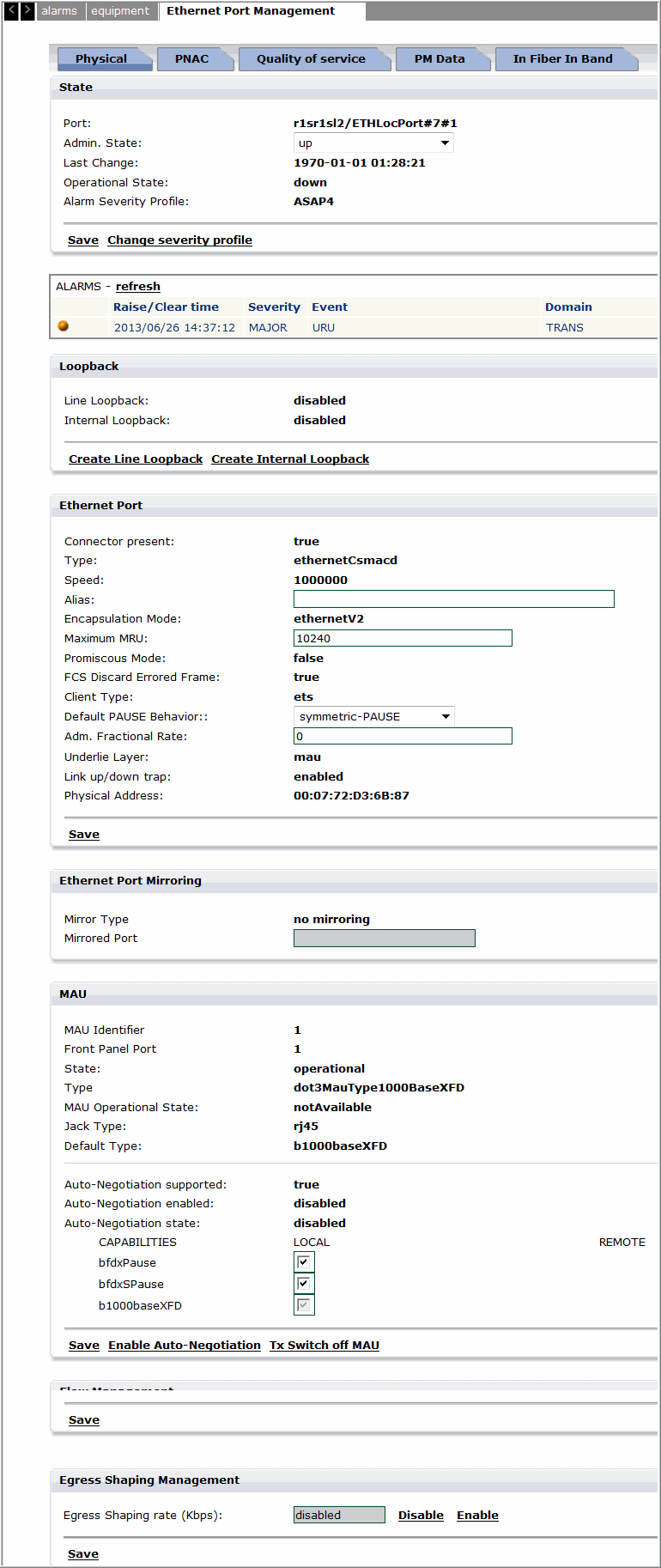 End of steps |
State
In this panel the settings of the resource can be modified by means of the following parameters:
-
Admin state - Allows to set the administrative state. The choices are: up = active state or down = not active state.
-
Last change - Specifies the date and time when the resource had been managed last time.
-
Operational state - Specifies the actual state of the resource.
-
MAU Operational state - Specifies the actual state of the Medium Access Unit (MAU).
-
Alarm Severity Profile - Specifies the ASAP label that is in use for the resource.
Ethernet Port
-
Connector present - Indicates if the interface has a physical connector. The values are: true or false.
-
Type - Indicates the type of port (fixed to "ethernetCsmacd"). The values fixed: ethernetCsmacd.
-
Speed - Indicates the actual configured rate. The values are: 1000000 (1 Gb/s) or 10000000 (10 Gb/s).
-
Alias - Indicates the friendly name for the interface that can be set by the user.
-
Encapsulation mode - Indicates the method of MAC packets encapsulation inside the underlying physical layer. The values are: ethernetV2 (default) or IEEE8023.
-
Maximum MTU/MRU - Indicates the Maximum Transmit Unit/Maximum Receive Unit size of the largest packet that can be sent/received on the interface, specified in octets. The value ranges from 1574 to 9242 (R1.0) or from 1574 to 10240 (From R4.0).
-
Promiscuous mode - Indicates indicating whether this interface has to inspect the packets' MAC addresses. The values are: true or false.
-
FCS discard errored frame - Indicates the insertion or removal of GFP-FCS (Frame Check Sequence) field into the optional field FCS of the GFP frame. The values are: true or false.
-
Client type - Indicates the transported layer. The values are: ets (for Ethernet Transparent System), etb (for Ethernet Bridge System) or LinkAgg (for Link Aggregation System).
-
Underlie layer - Indicates the associated layer. The allowable values are: mau (for Ethernet Transparent System), vconc (virtual concatenation to permit the setting of the "virtual-concatenation granularity" mode) or sdh (to permit the setting of the "Rate-Limiting" mode. NOTE: this value is given only in the case that the concatenation number for the VC4 is equal to 1).
-
Link up/down trap - Indicates whether linkUp / linkDown traps (notification upon the changing of the node operational state from up to down and vice versa) should be generated for this interface. possible options: enabled / disabled the associated layer. The values are: enabled or disabled.
Ethernet Port Mirroring
The Ethernet port mirroring allows duplicating traffic of a mirrored port in a service and sending a copy of this traffic to another dedicated port without affecting the service.
-
Mirror Type - Displays the type. The allowable types are no mirroring, mirroring input, mirroring output.
-
Mirrored port - Select the Ethernet port from the list whose traffic has to be duplicated.
MAU
The panel has the Save hyperlink in order to save the settings.
-
MAU panel - Allows to change the settings of the resource and displays the following parameters:
-
MAU identifier - Specifies a number assigned by the system. The value is: 1.
-
Front Panel Port - Specifies a number assigned by the system; it is the identifier of the physical port on the front of the PIM. The value is: <8 digit number>.
-
State - Specifies the MAU current status. The values are: operational or shutdown.
-
Jack Type List - Specifies the available connectors type. The values are: RJ45 for FE port or fiberLC for GBE port.
Note: Use AN-enable for GE interworking between the TSS-5C and TSS-320.
-
Jabber type - Specifies the state of the jabber process (checking about abnormal data transmissions longer than the max permissible packet length).
-
Default Type - Specifies the type of physical I/F. The values are:
• b1000BaseXFD for 1GE (1000Mbps) LAN
-
Auto-negotiation supported - Indicates if the auto-negotiation is supported or not. The values are: true or false.
-
Auto-negotiation enabled - Indicates if the auto-negotiation is enabled or not. The values are: enabled or disabled.
The panel has the following hyperlinks:
Save link - To save the settings.
Enable autonegotiation - To change the last described field without using other page command.
Flow Management
-
Flow management panel - Allows to change the settings of the resource and displays the following parameters:
-
(T)MPLS Management panel - Click CREATE MPLSIF link to create new MPLSIF.
Configure Port Scheduling and Shaping
1 |
Navigate to the Port in the main menu and click on the port, the port management screen is displayed. |
2 |
Specify the Egress scheduling rate in Kbps. Click Enableto enable egress port shaping. Clicking Disable will disable the egress port shaping. Note: The NE has the capability of supporting a total of four MPLS ports (including the main board and the 08FXK board). End of steps |
Configure MPLSIF
1 |
Click on MPLSIF under the TMPLS Management section to configure MPLSIF as shown in Figure 3-56, Configure MPLSIF and described in Table 3-17, Configure MPLSIF parameters. Figure 3-56: Configure MPLSIF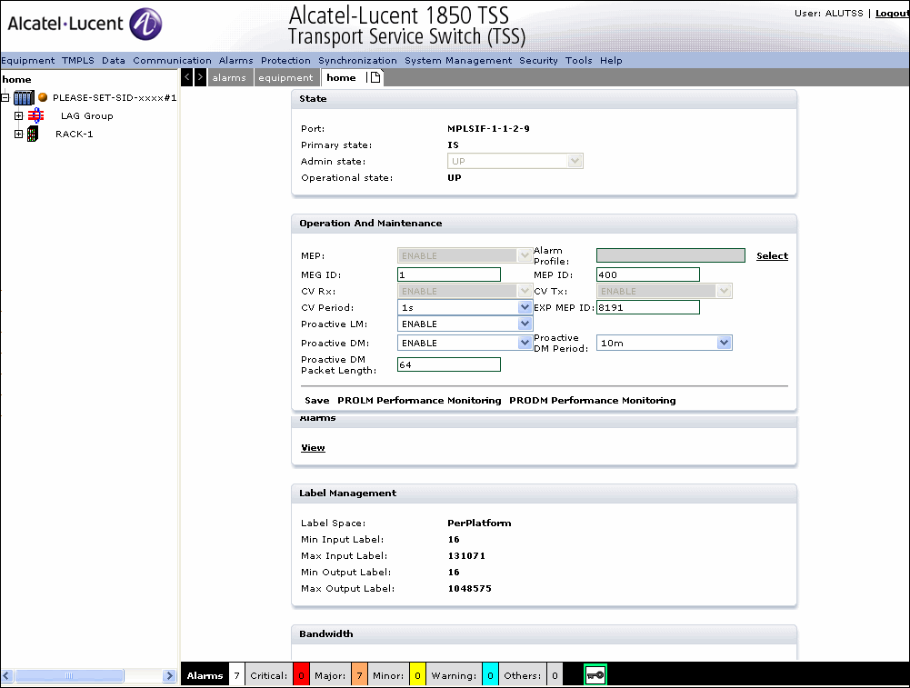 Table 3-17: Configure MPLSIF parameters |
2 |
Click Save to save the MPLSIF configuration. |
3 |
To configure PROLM Performance Monitoring parameters, click on the PROLM performance monitoring tab and configure the PROLM Performance Monitoring parameters as described in Step 17 to Step 29. |
4 |
To configure PRODM Performance Monitoring parameters, click on the PRODM performance monitoring tab and configure the PRODM Performance Monitoring parameters as described in Step 17 to Step 29. End of steps |
Quality of Service tab
1 |
The Quality of Service tab displays the following as shown in Figure 3-57: Quality of Service tab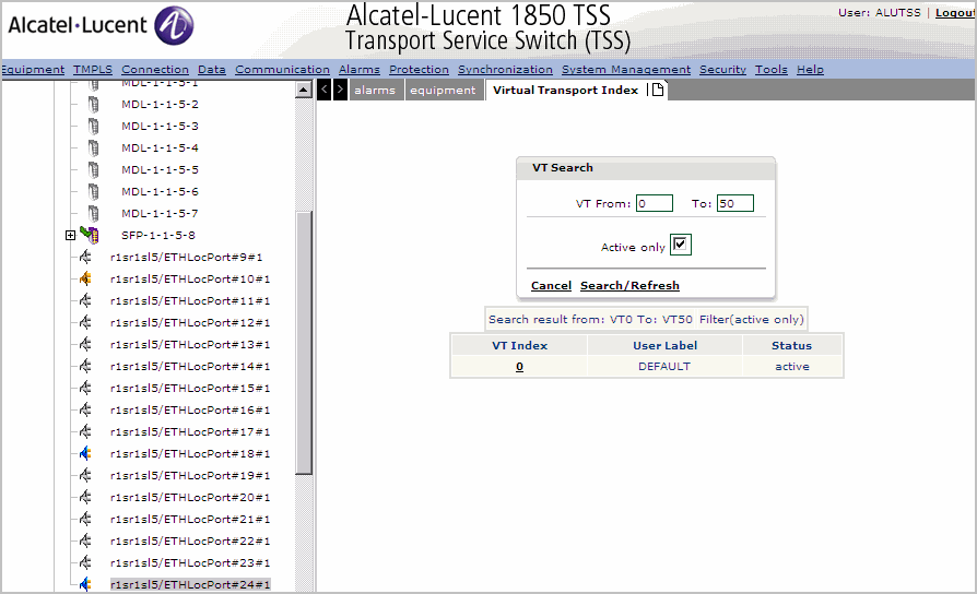 |
2 |
The Quality of service tab displays the VT for the selected port. Specify the VT range and click Search/Refresh to retrieve the VT profile. |
3 |
Click on the VT Index number to display the modify the VT parameters. Figure 3-58: Modify a Virtual Transport profile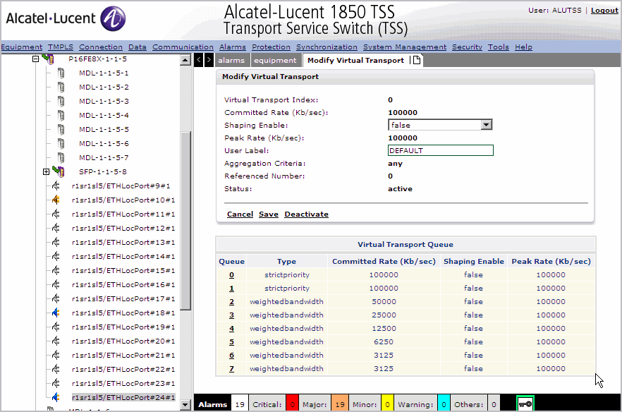 |
4 |
Click on the Queue to modify the VT queue profile as shown in Figure 3-59, Modify VT Queue Figure 3-59: Modify VT Queue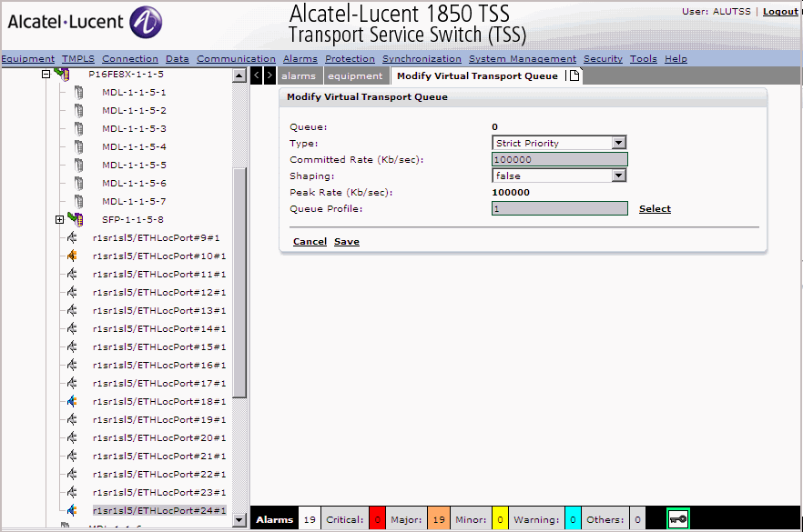 |
5 |
Select the Queue Type Strict Priority or Weighted Bandwidth. |
6 |
Specify the Committed Rate when queue type is Weighted Bandwidth. |
7 |
Specify the shaping as true or false and the peak rate in Kb/sec. |
8 |
Specify the associated queue profile. |
9 |
Click Save to save the changes or Cancel to return to the previous screen without saving. |
10 |
Click Cancel to cancel and return to the previous screen. |
11 |
Click Save to save the profile changes. |
12 |
Click Deactivate to deactivate the profile. End of steps |
PM Data tab
1 |
Click the PM data tab the Performance Monitoring screen is displayed as shown in Figure 3-60, Performance Monitoring Data. Figure 3-60: Performance Monitoring Data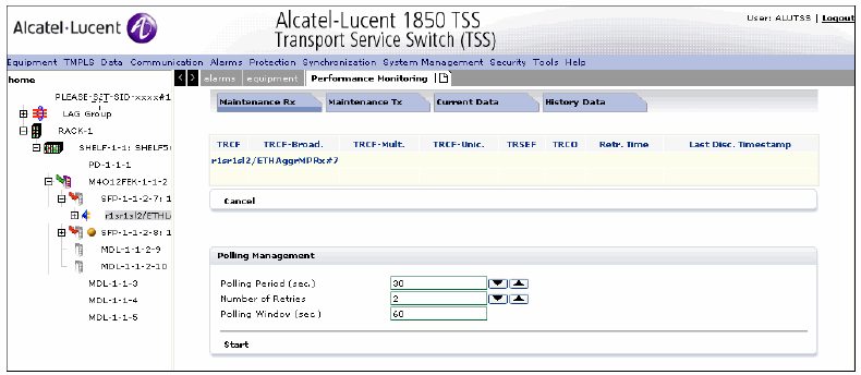 The Performance Monitoring tab displays the following functional tabs: | ||||||||||||||
2 |
Click the Maintenance Rx tab to display the Maintenance Rx parameters as shown in Figure 3-61, Maintenance Rx tab Figure 3-61: Maintenance Rx tab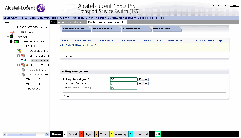 | ||||||||||||||
3 |
Specify the Maintenance Rx/Tx parameters as described in Table 3-18, Maintenance Rx/Tx parameters Table 3-18: Maintenance Rx/Tx parameters
| ||||||||||||||
4 |
Click the Maintenance Tx tab to display the Maintenance Tx parameters as shown in Table 3-18, Maintenance Rx/Tx parameters 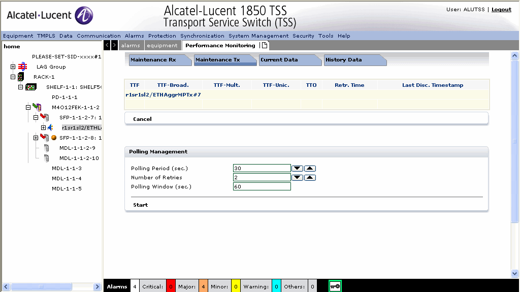 | ||||||||||||||
5 |
Specify the Maintenance Tx parameters as described in Table 3-18, Maintenance Rx/Tx parameters | ||||||||||||||
6 |
Click the Current Data tab to view the performance counters and create PM as shown in Figure 3-62, Current Data. Figure 3-62: Current Data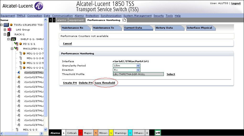 The Current Data tab displays the following panels: Figure 3-63: Create PM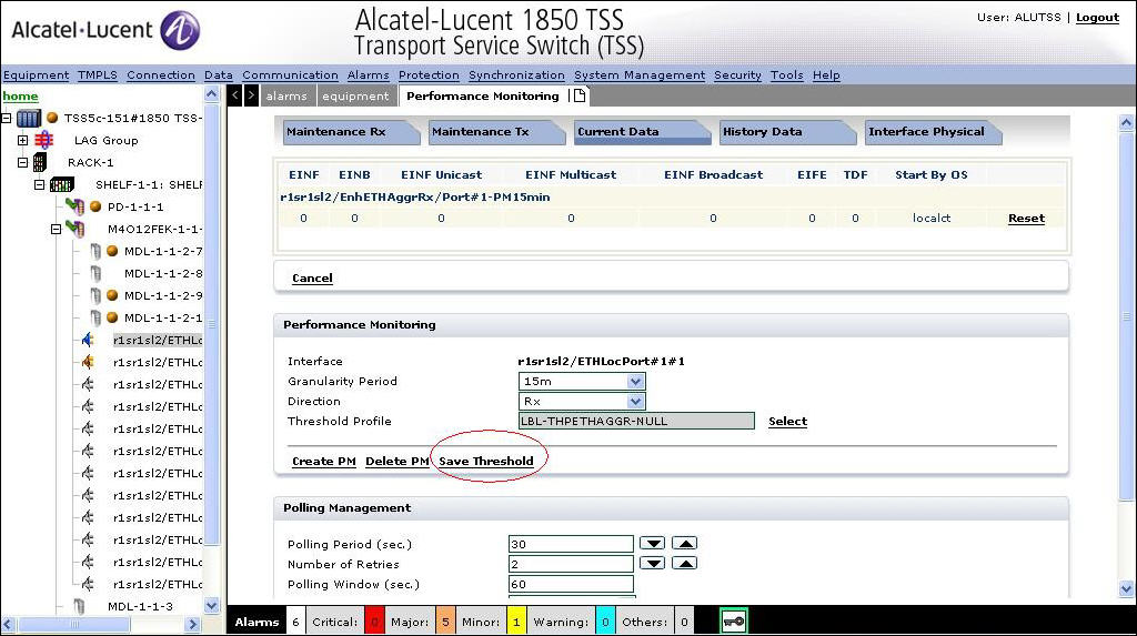 | ||||||||||||||
7 |
Click Create PM to create. Specify the PM and Polling Management parameters and click Start/Stop to increment or decrease the counters. End of steps |
Performance Monitoring panel
The Performance Monitoring panel displays the following parameters:
-
Granularity Period - Specifies the granularity period for monitoring the performance. The values are 15m to 24h.
-
Direction - Specifies the direction. The values are Rx and Tx.
-
Threshold Profile- Specifies the PM threshold profile based on the granularity period.
Polling management
The Polling Management panel has the same parameters as shown in Table 3-18, Maintenance Rx/Tx parameters.
CES PM Tab
1 |
Click the PM data tab the Performance Monitoring screen is displayed as shown in the following figure. Figure 3-64: CES Performance Monitoring Data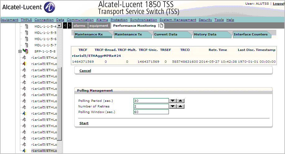 The Performance Monitoring tab displays the following functional tabs: | ||||||||||||||||||
2 |
Click the Maintenance Rx tab to display the Maintenance Rx parameters as shown in the following figure. Figure 3-65: CES Maintenance Rx Tab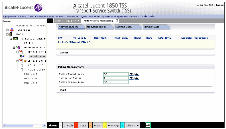 | ||||||||||||||||||
3 |
Specify the Maintenance Rx parameters as described in Table 3-18, Maintenance Rx/Tx parameters | ||||||||||||||||||
4 |
Click the Current Data tab to view the performance counters and create PM as shown in the following figure. Figure 3-66: CES Current Data Tab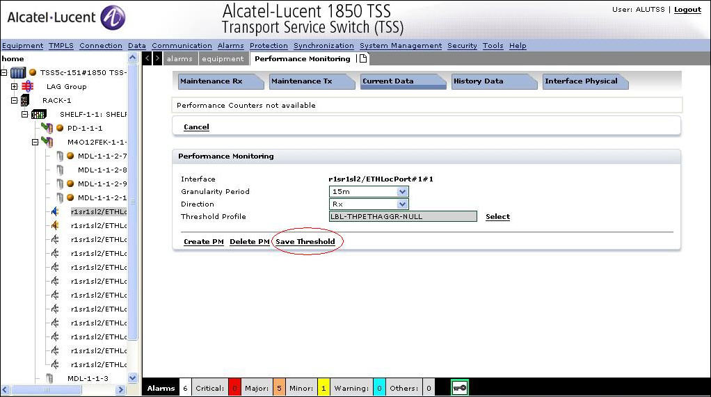 | ||||||||||||||||||
5 |
Click the History Data tab the Performance Monitoring screen is displayed as shown in the following figure. Figure 3-67: CES History Tab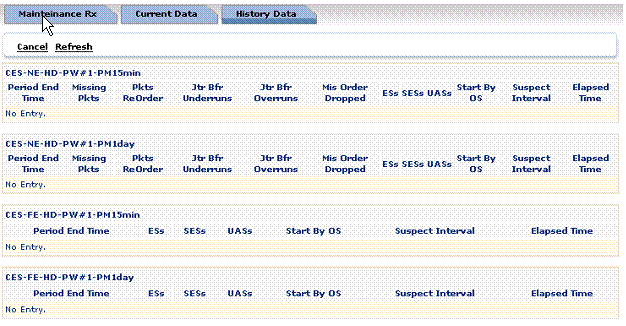
The History Data tab displays the history details of rlsrls9ETHAggrRx/Port#1 port. | ||||||||||||||||||
6 |
Specify the following PM parameters as described in the following table: Table 3-19: PM Parameters Tab
End of steps |
In Fiber In Band
1 |
After configuration of the MPLSIF, the In fiber In Band tab is displayed as shown in Figure 3-68, MPLSIF Ethernet Port Management Figure 3-68: MPLSIF Ethernet Port Management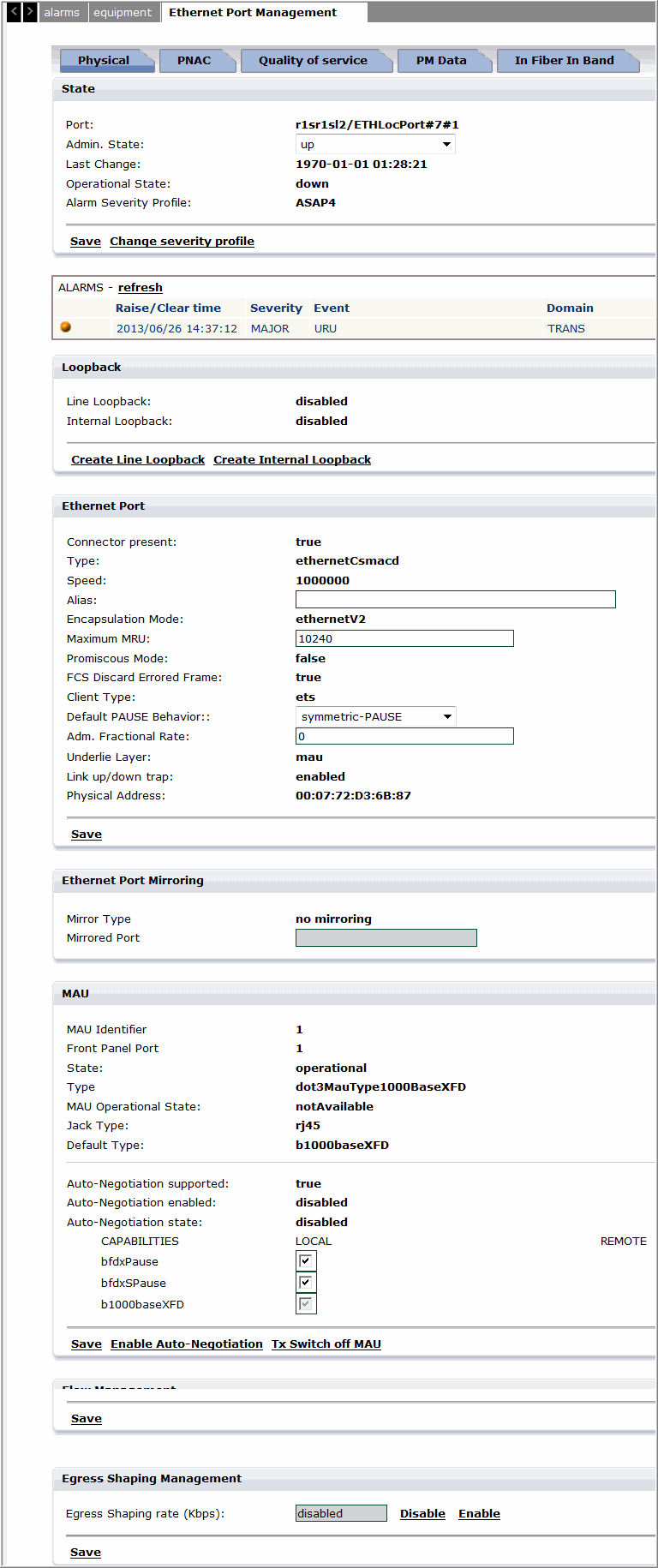 |
2 |
Click on the In Fiber In Band tab, the screen is refreshed to display the In Fiber In band configuration screen as shown in Figure 3-69, In Fiber In Band Management Figure 3-69: In Fiber In Band Management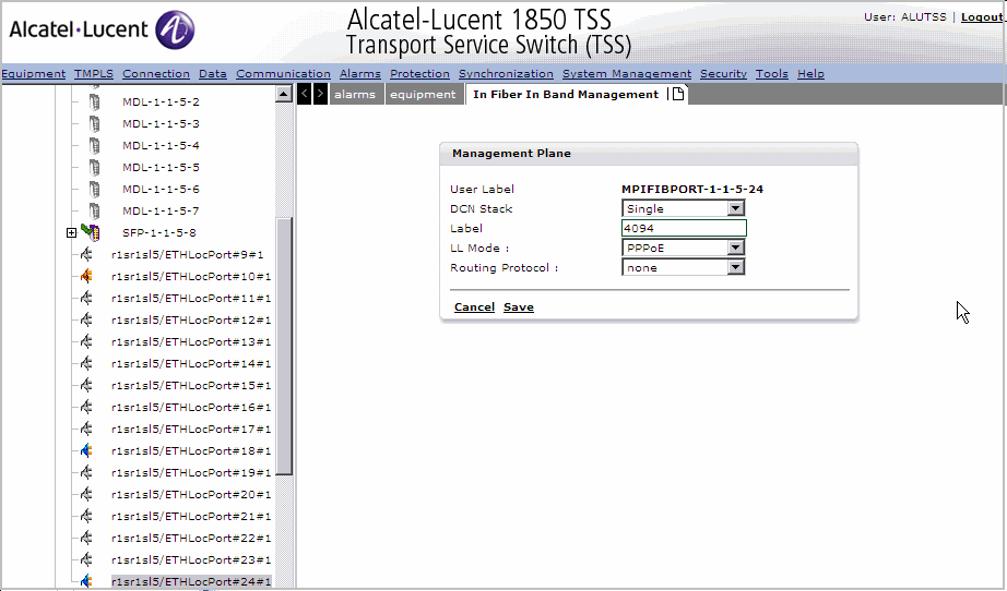 |
3 |
Modify and click Save to save the In fiber in band management settings or click Cancel to return to the previous screen. |
4 |
Click Activate to activate the In fiber In Management setting as shown in Figure 3-70, Activate In Fiber In Band Management Figure 3-70: Activate In Fiber In Band Management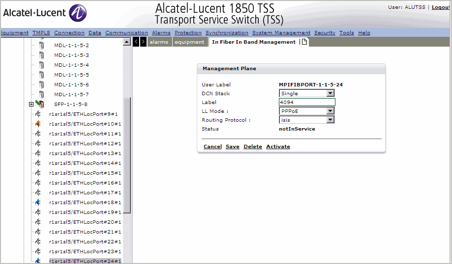 |
5 |
Click Deactivate to deactivate the In Fiber In Band Management. End of steps |
PNAC tab
1 |
Click the PNAC tab to configure PNAC parameters. Refer the Procedure 3-81: Configure PNACsection for configuration and management of PNAC parameters. End of steps |
Port Management restrictions
The following are the port management restrictions:
-
Main board: 6FE ports are guaranteed (1~6), 2 GE ports are guaranteed (7~8).
-
Option slot 1: any option board can be assigned in the slot with full capacity.
-
Option slot 2: if O16E1/OTRI board, full capacity; is not allowed (not blocked by SW, if assigned, port 1~2 can be used); in case the OTRI board is used, and in the future STM-1 CES is used, the FE port 15 and 16 on main board should not be used (note: not blocked by SW). For slot 2 O8FEK is allowed full capacity.
-
If the OTRI board is used in the first (or second) option slot, the GE port 9 (or 10) on main board cannot be used.
-
Option slot 2 for OFXK is allowed if the assigned ports 11-16 on main board are blocked.
Table 3-20: FE port arrangement (Scenario R4.0)
|
Configuration |
Main Slot |
Main Usage |
1st Option slot |
1st Usage |
2nd Option slot |
2nd Usage |
|---|---|---|---|---|---|---|
|
1 |
12 |
11~16 not |
8 OFEK/O8FXK |
OK |
8 O8FEK/O8FXK |
6: main 11~16 |
|
2 |
12 |
15/16 not |
8 O8FEK/O8FXK |
OK |
4 OTRI |
2 main 15/16 |
|
3 |
12 |
11~16 not |
OTRI |
OK |
8 O8FEK/O8FXK |
6 main 11~16 |
|
4 |
12 |
OK |
8 O8FEK/O8FXK |
OK |
2 O16E1/R202E |
0 |
|
5 |
12 |
11~16 not |
2 O16E1/R2O2E |
OK |
8 O8FEK/O8FXK |
11~16 not |
|
6 |
12 |
OK |
2 O16E1/R2O2E |
OK |
2 O16E1/R2O2E |
OK |
|
7 |
12 |
15/16 not |
2 O16E1/R2O2E |
OK |
OTRI |
2 main 15/16 |
|
8 |
12 |
OK |
4 OTRI |
OK |
2 O16E1/R2O2E |
OK |
|
9 |
12 |
15/16 not |
4 OTRI |
OK |
4 OTRI |
2 main 15/16 |
Note: Always put the option board which needs higher FE capacity in option slot Requested FE capacity: O8FEK/O8FXK > OTRI > O16E1.
Table 3-21: GE port arrangement (Scenario R4.0)
|
Configuration |
Main slot usable GE ports |
1st option slot |
2nd option slot |
|---|---|---|---|
|
1,4,5,6 |
7, 8, 9,10 |
Not OTRI |
Not OTRI |
|
3,8 |
7, 8, 10 |
OTRI with GE |
Not OTRI |
|
2,7 |
7, 8, 9 |
Not OTRI |
OTRI with GE |
|
9 |
7, 8 |
OTRI with GE |
OTRI with GE |
Note: The NE supports a total of four GE switches.
Alcatel-Lucent – Proprietary
Use pursuant to applicable agreements