Procedure 3-80: Administer 1588 PTP clock mode
Use the following procedure to synchronize the clock management:
1 |
Select Synchronization ->1588 -> PTP Clock Mode from the menu bar as shown in Figure 3-184, PTP Clock Mode. Figure 3-184: PTP Clock Mode The supported parameters are described in Table 3-78, PTP Clock Mode Table 3-78: PTP Clock Mode |
2 |
Click Save to save the clock mode. End of steps |
PTP Default Clock configuration
1 |
Select Synchronization ->1588 -> PTP Default clock cfg from the menu bar as shown in Figure 3-185, PTP Default Clock configuration. Figure 3-185: PTP Default Clock configuration |
2 |
To view the clock settings, click the name of the clock. End of steps |
Modify PTP Default Clock Configuration
Use the following procedure to modify the PTP Default Clock Configuration:
1 |
Select the name of the PTP clock form the list as shown in Figure 3-185, PTP Default Clock configuration. |
2 |
The following screen is displayed as shown in Modify PTP Default Clock Configuration 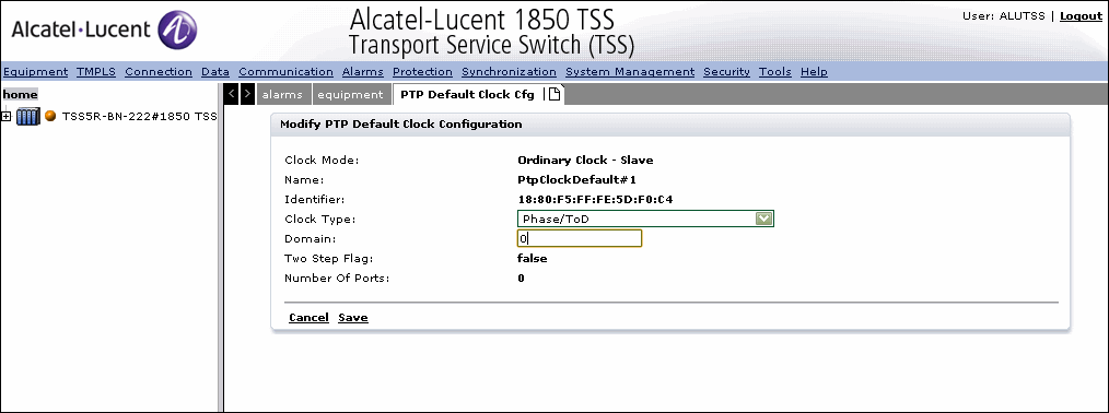 |
3 |
The supported parameters are described below: End of steps |
PTP clocks
1 |
Select Synchronization ->1588 -> PTP clocks from the menu bar as shown in Figure 3-186, PTP clocks. Figure 3-186: PTP clocks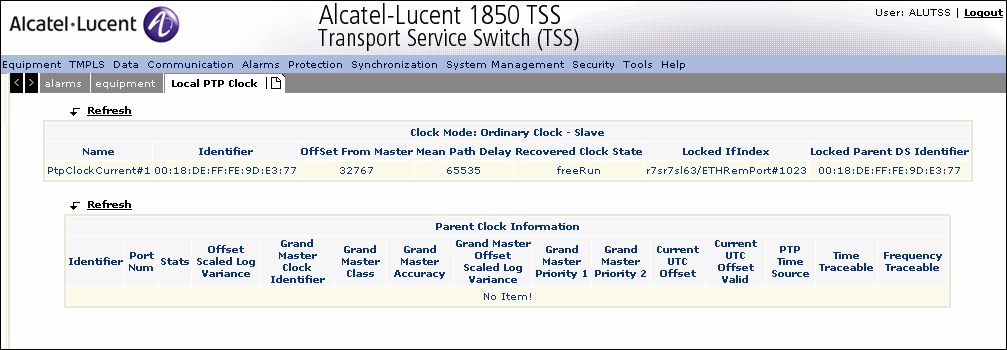 |
2 |
Click Refresh to refresh the Local PTP clock listing. End of steps |
Modify Local PTP Clock
Use this procedure to Modify local PTP clock:
1 |
Select the name of the PTP clock from the list as shown in Figure 3-186, PTP clocks. |
2 |
The following screen is displayed as shown in Figure 3-187, Modify Local PTP Clock Figure 3-187: Modify Local PTP Clock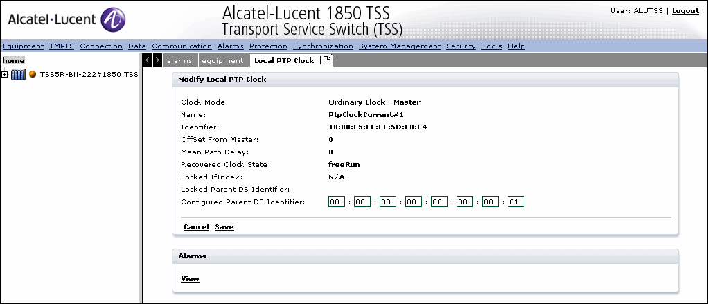 |
3 |
Click Save to save the configuration. End of steps |
PTP Ports
1 |
Select Synchronization ->1588 -> PTP ports from the menu bar as shown in Figure 3-188, PTP Ports. Figure 3-188: PTP Ports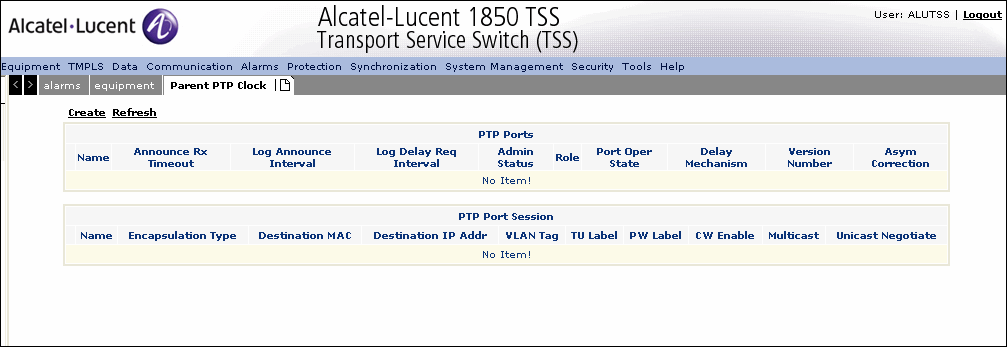 |
2 |
Click Create to create a PTP port as shown in Figure 3-189, Create PTP port. Figure 3-189: Create PTP port |
3 |
Select the Port Type from the drop-down. The supported values are Physical port and 1:1 linear TMPLS protection group. If 1:1 group is selected, FFP options are provided. |
4 |
Click Select to select the port to apply the PTP as shown in Figure 3-190, Select the physical port Figure 3-190: Select the physical port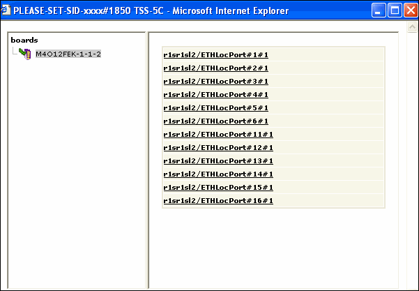 |
5 |
Click Create to create the PTP port or click Cancel to return to the previous screen without saving. |
6 |
Click Refresh to refresh the Local PTP clock listing. |
7 |
To delete a PTP port, ensure that the admin status of the PTP port shows as disabled and no active PTP sessions are existing. Check the checkbox provided for the port and click Delete. End of steps |
Modify PTP Port
1 |
To modify the PTP port, navigate to the Config PTP Port/Session screen and select the port to modify as shown in Figure 3-191, Modify PTP Port Figure 3-191: Modify PTP Port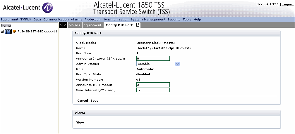 |
2 |
Modify the parameters as described in the section on Create PTP ports. |
3 |
Click Save to save the modifications or click Cancel to return to the previous screen without saving. |
4 |
To Delete the PTP port, ensure that the admin status of the PTP port shows as disabled and no active PTP sessions are existing. Check the checkbox provided for the port and click Delete. |
5 |
Click Refresh to refresh the configured PTP port list. End of steps |
Create a PTP Session
1 |
After creating the PTP port, Click Create under PTP session to create the PTP session as shown in Figure 3-192, Create PTP Session Figure 3-192: Create PTP Session |
2 |
Click Create to create a new session. |
3 |
Select the PTP port and specify the Session Id. |
4 |
Click Save to save the configuration or click Cancel to return to the previous screen without saving. End of steps |
Modify the PTP session
1 |
Modify the parameters as described in the section on Create PTP session. |
2 |
Click Save to save the modifications or click Cancel to return to the previous screen without saving. |
3 |
To Delete the PTP session, check the checkbox provided for the session and click Delete. |
4 |
Click Refresh to refresh the configured PTP session list. End of steps |
External Interfaces
1 |
Select Synchronization ->1588 -> External Interfaces from the menu bar as shown in Figure 3-193, External Interfaces. Figure 3-193: External Interfaces |
2 |
To modify an external interface, click on the name the modify external interfaces screen is displayed as shown in Figure 3-194, Modify External Interfaces. Figure 3-194: Modify External Interfaces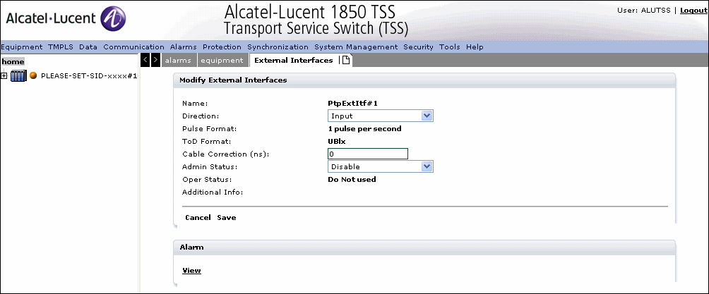 |
3 |
Modify the Direction as Input or Output |
4 |
Modify the Cable Correction in the value range of -100ms:100ms. |
5 |
Set the Admin status as enabled or disabled. |
6 |
Click Save to the save the modifications or click Cancel to return to the previous screen without saving. |
7 |
Click View, to view the list of alarms. End of steps |
Alcatel-Lucent – Proprietary
Use pursuant to applicable agreements