Fixed Wireless Access sessions
FWA sessions obtain network connectivity through a mobile RAN such as (e-)UTRAN (4G) or NR (5G). FWA sessions use the same BNG-UP, charging, authentication, and address management methods (including ODSA) as fixed BNG sessions.
Introduction to FWA
Because FWA sessions obtain network connectivity through a mobile RAN such as (e-)UTRAN (4G) or NR (5G), there are two important differences with fixed access sessions.
- The initial setup is performed out-of-band and is signaled directly to the MAG-c which acts as a PGW-C, SGW-C + PGW-C, or SMF, whichever is applicable.
- Sessions have tunneled IP connectivity from the client device to the FWA-UP, which acts as a 4G PGW-U, 4G SGW-U + PGW-U, or 5G UPF, whichever is applicable.
Because FWA sessions are BNG subscriptions, they have the same service requirements as fixed sessions. QoS, service selection, pool management, and charging are also applicable to FWA sessions.
FWA sessions often use mobile-specific terminology. The following lists the most common terms and how they map to an FWA deployment.
- User Equipment (UE)
- The end device used by the subscriber. The UE and RG can be integrated in one device or can be two separate devices.
- International Mobile Subscriber Identity (IMSI)
- A globally unique number identifying the subscriber. For FWA, the IMSI is mapped
to a subscriber ID. Its value consists of the following three sub-fields.
- Mobile Country Code (MCC): uniquely identifies a country
- Mobile Network Code (MNC): uniquely identifies a mobile network within the country
- Mobile Subscriber Identification Number (MSIN): a second globally unique number identifying the subscriber
- Mobile Station International Subscriber Directory Number (MSISDN)
- For mobile subscriptions, the public and well-known phone number. For FWA sessions, it can be used as an identifier for compatibility with AAA systems that are mostly MSISDN based.
- International Mobile Equipment Identity (IMEI)
- A unique identifier for the hardware device used for the connection. Part of the IMEI is the Type Allocation Code (TAC) which is allocated to a specific device model.
- Packet Data Network (PDN)
- A network the subscriber connects to; for example, the public Internet.
- Access Point Name (APN)
- Identifies a specific PDN but can also be used to identify a specific gateway
within a PDN, or even a specific service type within a PDN. A single UE can be
connected to multiple APNs. Each such session is called a PDN session. This
model maps directly to FWA and is also common with fixed BNG sessions. An APN
consists of the following two sub-fields.
- Network Identifier (NI): defines the network (PDN).
- Operator Identifier (OI): defines the operator’s mobile network in which the PDN gateway resides. This consists of the operator’s MNC and MCC. This field is optional.
- Radio Access Network (RAN)
- The antennas providing wireless connectivity.
- Radio Access Bearer (RAB)
- A radio channel between a UE and the RAN. Multiple RABs per PDN session can exist.
Residential Gateway models
For FWA, there are two common models for a RG.
- An integrated model where the RG provides classic BNG RG functions and acts as a mobile UE. A single IP address can be used to manage this entity. The RG or UE authentication is based on mobile SIM authentication.
- A separate model where there is a logical RG function and a logical UE function. The MAG-c abstracts from how these functions are connected. Often both functions require their own address for management purposes. It is possible to do additional RG device authentication based on PAP/CHAP.
- An integrated RG and UE can have a separate outdoor unit for radio signaling and therefore, can consist of two hardware components.
- A separate model can be a single hardware device that implements the RG and UE function separately with an internal link.
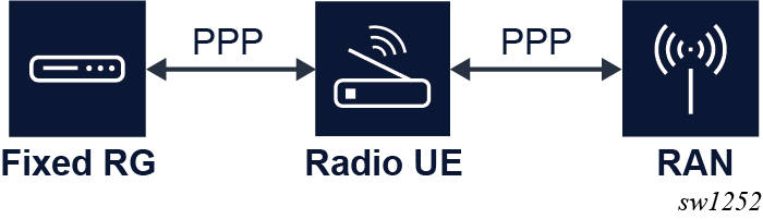
The following figure shows a model using a PPP link between the RG and the UE.
Selected and real APN
When a session is initially set up, only one APN is available, as signaled during session management (for example, in the GTP Create Session Request message). This APN is known as the real APN. It is used to pick up a BNG authentication flow that is configured using the authentication-flow command in the config>mobile>pdn>apn>fixed-wireless-access context.
After initial authentication, a new APN can be returned. This APN is known as the selected APN or the virtual APN. It determines the service selection for the FWA session. If no new APN is returned, the selected service is based on the real APN.
- real
The real, unmodified APN is used as is, including the OI if it was signaled. For example, the received APN equals
internet.mnc001.mcc001.gprsand is used as is. - real-ni-only
The real APN is used, but without the OI part if it was signaled. For example, the received APN equals
internet.mnc001.mcc001.gprsand is used asinternet. - selected
This is the default option. The selected APN is used as is. If no selected APN is available, the system falls back to the real-ni-only option.
| Use case | Context |
|---|---|
|
Use the APN as a match criterion in the ADB. The APN format only applies if the attribute parameter in the match command equals apn. |
config>mobile>profile>adb>match |
|
Reflect the APN in the Called-Station-Id attribute for RADIUS authentication. The APN format also applies to the username, if the user-name-format fixed-wireless-access format command in the same context is configured to include the APN. Note: If the mobile UE sends a PPP username as
a PCO during session setup signaling, the username is reflected
as is. The apn-format command in this context
does not modify the username even if it contains an APN.
|
config>mobile>profile>bng>radius-authentication-profile |
|
Reflect the APN in the Called-Station-Id attribute for RADIUS accounting. Note: The user-name attribute from the
authentication is reflected as is in RADIUS accounting. The
apn-format command in this context does
not modify the username in accounting even if it contains an
APN.
|
config>mobile>profile>charging>bng> radius>session |
Session identification, subscriber identification, and multi-APN support
For FWA sessions, the MAG-c subscriber key is the IMSI and the FWA session key is the pair (IMSI, APN). So multiple FWA sessions can be set up for the same UE/RG if those sessions use a different APN. This is called multi-APN support. The following lists some use cases of how multi-APN can be used.
- Have a different APN for Internet, video, and voice services.
- Have a different APN for public Internet and private work-from-home VPN connections.
- Have a different APN for a UE management IP address in case of the separated UE/RG model.
Each session can be mapped to a different L3 service and a different FWA-UP. For example, to optimize the BNG-UP resource usage, a low-throughput management-only session can be installed on a different FWA-UP than a high-throughput Internet session.
FWA-UP selection
- Define a UP peer list using the up-peer-list command in the config>mobile>profile>pfcp context.
- Configure all FWA-UPs as peer in the UP peer list using the peer command in the config>mobile>profile>pfcp>up-peer-list context. The IP address to use as parameter in the peer command is the source IP address of the PFCP association of the FWA-UP.
- Set the FWA-UP selection to true for each peer using the upf-selection command in the config>mobile>profile>pfcp>up-peer-list>peer context.
- Configure the APNs that are supported on the peer using the apn command in the config>mobile>profile>pfcp>up-peer-list>peer context.
- Make a reference to the configured UP peer list using the up-peer-list command in the config>mobile>pdn context.
When a session is set up, it automatically selects a peer from the UP peer list that is enabled for that APN. Load-balancing over the FWA-UPs is done in a round-robin fashion.
Address signaling methods and deferred allocation
The 3GPP specifications define two methods to signal an allocated IPv4 address.
- directly in NAS messaging during session setup
From MAG-c point of view, the address is included in the session setup messages; for example, in the GTP Create Session Response message.
- via DHCP
The IPv4 address is signaled after the session setup completes.
Which method is used depends on the following parameters, in order of precedence. Each parameter can be absent, or can have the value NAS or DHCP.
- the Alc-FWA-IPv4-Signaling-Method RADIUS VSA
- the configuration of the ipv4-signaling-method command in the config>mobile>profile>adb>entry>fixed-wireless-access context
- the 00AH (IP address allocation via NAS signaling) and the 000BH (IPv4 address allocation via DHCPv4) PCOs as signaled by the UE. If only one is present, that method is used.
- the configuration of the default-ipv4-signaling-method command in the config>mobile>pdn>apn>fixed-wireless-access context of the selected APN where the session is created
- NAS, by default
If IPv6 is enabled, a UE/RG interface-identifier is derived from the link-local address of the MAG-c. This interface-identifier is signaled via NAS to the UE/RG, which derives a link-local address from it when needed; for example, to send ICMPv6 RS messages.
IPv6 global addresses always use deferred allocation and are signaled in-band after session setup completion. In case of SLAAC, the UE/RG can optionally use the signaled interface-identifier to construct a global address.
For FWA, deferred allocation can be used to assign an address to an RG function in the separated UE/RG model. In this case, the UE can forward the relevant DHCP, DHCPv6, or ICMPv6 messages to the RG without maintaining the stack itself.
QoS
FWA sessions support the generic BNG QoS functionality and are additionally subject to specific mobile QoS constructs. This topic gives a high-level overview of how mobile QoS works. For information about the specific subset that is supported for FWA, see 4G QoS attributes.
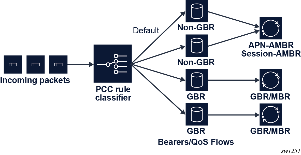
In mobile networks, the concept of a bearer (4G), or a QoS flow (5G), defines the QoS. At least one default bearer or QoS flow exists to which all traffic is mapped by default. More dedicated bearers and QoS flows can be created to which specific traffic is mapped using PCC rules.
Each bearer or QoS flow is classified as either GBR or non-GBR, and QoS treatment on the BNG-UP is applied accordingly. The specified rate values are sent to the BNG-UP using PFCP QER IEs.
- GBR bearer or QoS flow: a GBR and an MBR value are applied.
- Non-GBR bearer or QoS flow: a common MBR is applied to all bearers or QoS flows of this session. For 4G, this value is known as the APN-AMBR, for 5G this value is known as the session AMBR.
The following figure shows a high-level example of QoS handling. It shows a setup with four bearers or QoS flows, of which two are GBR and two are non-GBR (including the default).
Each bearer or QoS flow has QCI (4G), 5QI (5G), and ARP (4G/5G) values. The RAN uses these values, which are transparent to the MAG-c and the FWA-UP, with the exception of the GBR or non-GBR determination of the bearer or QoS flow.
- For 4G, standardized QCI values and the corresponding GBR or non-GBR classification are specified in 3GPP TS 23.203 section 6.1.7.2.
- For 5G, standardized 5QI values and the corresponding GBR or non-GBR classification are specified in 3GPP TS 23.501 section 5.7.4.
- Both QCI and 5QI can be operator-specific, and in this case GBR or non-GBR classification is provisioned together with the QCI or 5QI provisioning. The operator-specific range is from 128 to 254 as defined in 3GGP TS 24.301 section 9.9.4.3 (4G) and 3GPP TS 24.501 section 9.11.4.12 (5G).
The access technology defines how the system learns the different values.
PAP/CHAP authentication
A mobile UE can send PAP/CHAP authentication credentials as a PCO option during the session setup signaling. When such a PCO option is received, the MAG-c uses these credentials in the authentication instead of the locally configured credentials.
- The PAP/CHAP username can be used for the relevant ADB match criteria. For RADIUS authentication, the username has precedence over the configuration of the user-name-format fixed-wireless-access format command in the config>mobile>profile>bng>radius-authentication-profile context.
- The PAP/CHAP credentials are reflected in RADIUS instead of the password configured in the config>mobile>profile>bng>radius-authentication-profile context.
PAP/CHAP authentication is typically used for separate RG/UE models, where a PPP link is present between the RG and UE. PAP/CHAP authentication is performed over the link. The UE pretends successful authentication of PAP/CHAP and moves the session to the NCP state. The MAG-c gets a CHAP challenge and a CHAP response in PCOs. In cases where the PAP/CHAP based authentication on the MAG-c fails, the UE tears down the PPP session using the LCP terminate messages.
Session lifetime and held addresses
The session management procedures define the lifetime of an FWA session; for example, a GTP Delete Session Request message. An FWA session can exist without any stack being signaled to the client if deferred allocation is used. Stack timeouts do not drive session deletion. If a session management procedure deletes a session with active IP stacks, those stacks are by default released.
For an integrated RG/UE, this is not a problem because the RG/UE knows of the session failure and knows that IP stacks are lost.
For a separated RG/UE model, the UE can have forwarded those stacks to a RG. Depending on the RG/UE connection model, it is possible that the RG is not aware of the failure and keeps using assigned addresses until their signaled lifetimes expire.
To solve this, FWA sessions support holding addresses when a session gets deleted. To configure this, use the address-hold-time command in the config>mobile>profile>adb>entry>fixed-wireless-access context. The hold time can be set to a fixed amount or be based on the longest remaining address lifetime. In both cases, the hold time is limited to 10 days.
When the hold time is configured, the MAG-c keeps a state for these addresses for the specified hold time. If the ODSA local address assignment allocated the addresses, the ODSA address hold time is automatically increased to the configured hold time. Other than that, there is no link between held addresses and the original allocation source of the addresses (for example, ODSA or AAA). For example, if a held address allocated by ODSA is removed, it is not explicitly released for ODSA. It needs to time out independently.
Held addresses are linked to the FWA session key pair (IMSI, APN). If a new session for the key of an held address is created, the held address is picked up and re-used. The interaction with specific address assignment methods is as follows:
- local address assignment (ODSA)
The new session requests the held address from ODSA. The request cancels any running ODSA hold time and ODSA links the address to the new session. In case ODSA cannot assign the address, the session setup fails; for example, ODSA was not the original allocation source of the held address.
- AAA
The held addresses are ignored and removed in favor of the AAA-signaled address.
Because held addresses do not interact with the original allocation method, Nokia recommends to only enable holding addresses when the address assignment source of a particular session is stable over session creation and deletion. If the address assignment source is not stable, session setups can fail or addresses can be hold for a long time. For example, consider a locally assigned ODSA address being put in the hold state for ten days. If the session is re-established but indicates an AAA address, the held address is not used and not released toward ODSA. The ODSA address keeps its ten day hold time and is not usable during that period.
Headless mode for FWA
Headless mode as described in section Headless mode is partially supported for FWA sessions. When the connection between the FWA-UP and the MAG-c fails, the currently installed sessions on the FWA-UP remain unaffected and continue forwarding data.
configure mobile-gateway profile pfcp pfcp-profile path-restoration-time4G and 5G NSA option 3 sessions
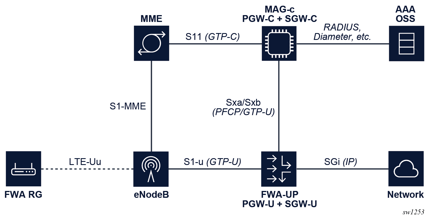
Basic FWA network shows the elements involved in a simple FWA network with a MAG-c operating as a combined PGW-C and SGW-C, and a FWA-UP operating as a combined PGW-U and SGW-U. The figure highlights the communication between the elements with the interface name if applicable and for the BNG relevant interfaces, the protocol being used. The high-level role of the MME, SGW, and PGW elements is as follows:
- MME
The MME orchestrates the basic connectivity of the UE and how this connectivity evolves during the lifetime of a session (for example, mobility, idling, paging).
- SGW
The SGW provides advanced data forwarding functionality such as buffering packets for idling UEs or providing a mobility anchor for inter-eNodeB mobility. Often this functionality is combined with a PGW in a single network element. In a CUPS environment the SGW is split in an SGW-C and an SGW-U element.
- PGW
The PGW provides PDN connectivity to an IP network. It can perform additional authorization to PDN-specific AAA servers; for example, authorization using the RADIUS protocol. It enforces charging functionality. In a CUPS environment the PGW is split in a PGW-C and a PGW-U element.
To enable 4G FWA sessions for a combined gateway, the GTP-C S11 and S5 interfaces need to be enabled on the MAG-c. The S5 interface is between the SGW and PGW and is internal for a combined gateway.
- To enable the S5 interface, use the gtp-c command in the config>mobile>pdn>s5>interface context. This interface is not necessarily used to terminate packets, but its IP must match the “PGW S5/S8 Address for Control Plane or PMIP” address that is signaled in the GTP Create Session Request.
- To enable the S11 interface, use the gtp-c command in the config>mobile>pdn>s11>interface context. This interface transfers the GTP-C packets.
- To identify the L3 service on the FWA-UP where the GTP-U packets are received, configure the s1u-interface-realm parameter of the gtp-c command in the config>mobile>pdn>s11>interface context.
- Configure the EPC node name using the epc-node command in the config>mobile>pdn context. The MCC and MNC value under this node must match the MCC and MNC of the IMSI for new FWA sessions. Otherwise the session is seen as roaming, which is not supported for FWA.
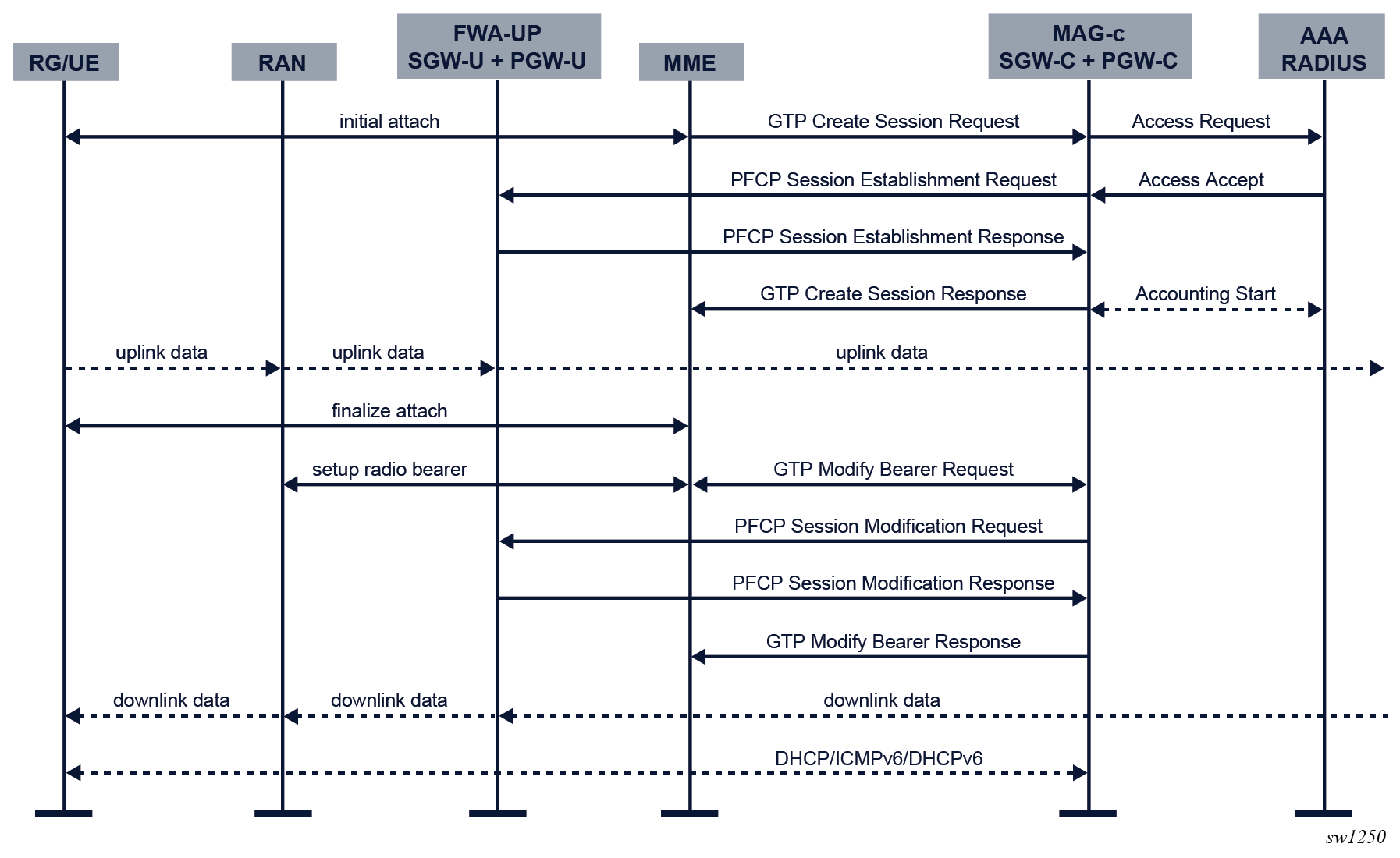
- An initial attach sequence is initiated between the UE and the MME, which leads
to a GTP Create Session Request message toward the MAG-c. This message contains three sets of parameters:
- protocol-specific data to initiate the stateful control session between the MME and the MAG-c
- the required identification and subscription parameters to initiate
session management for the PDN sessionNote: These parameters always include IMSI, IMEI, APN, PDN type, and can be extended with additional values such as MSISDN, static IP addresses, and APN-AMBR.
- PCOs sent from the client; for example, a request for DNS servers, a request for deferred allocation, or PDN-specific authorization using encapsulated PAP/CHAP messages
- Based on the signaled APN, the MAG-c looks up the APN under the config>mobile>pdn>apn context. To enable FWA functionality, the APN must be configured with an FWA node in the no shutdown state using the fixed-wireless-access command in the config>mobile>pdn>apn context. If there is no FWA node configured, it is not an FWA session and the regular mobile gateway session management applies. The authentication flow of the FWA node configured using the authentication-flow command in the config>mobile>pdn>apn>fixed-wireless-access context is used to authenticate the session. FWA-specific ADB match criteria or RADIUS include attributes can be used.
- The MAG-c selects a FWA-UP and sets up a PFCP session. The PFCP session carries the full session data, including all BNG-specific parameters. At this point, the RAN has not yet allocated a downlink GTP-U F-TEID, so the downlink data packet is buffered. For uplink traffic, the FWA-UP allocates an F-TEID and sends it to the MAG-c.
- The MAG-c sends a GTP Create Session Response message to the MME. This message includes the uplink GTP-U F-TEID as allocated by the FWA-UP. It includes the IPv4 address if one was allocated and signaled via NAS. The MME completes the attach toward the UE and sets up the radio bearers toward the RAN. At this point, uplink data traffic can be sent.
- As part of the radio bearer setup, the RAN allocates a downlink GTP-U F-TEID. The MME signals the downlink to the MAG-c using a GTP Modify Bearer Request Message. The MAG-c forwards it to the FWA-UP using a PFCP Session Modification Request message which changes the downlink rules from buffering to forwarding with the provisioned F-TEID. The FWA-UP acknowledges the PFCP message to the MAG-c. The MAG-c acknowledges the GTP message to the MME. At this point, downlink traffic is possible.
- The data layer connectivity is ready, but it is possible that not all IP addresses allocated to the RG are signaled to the UE. The addresses are signaled over the data connection using the DHCP, ICMPv6, and DHCPv6 protocols.
Mobility and idling
FWA supports the X2-based handover, the tracking area update, the UE triggered service request, the network triggered service request, and the S1 release procedures. Variants of these procedures with an SGW change are not supported.
Many of these procedures require interoperability with standard RAN deployments which assume these procedures are available by default. Handover procedures are useful to provide RAN resiliency, where a UE/RG switches to a new antenna using handover procedures if its current antenna fails.
Most of these procedures require updating the FWA-UP to handle the new traffic rules. This update is done using the PFCP Session Modification Request messages.
- For an X2-based handover, the F-TEID field in the Forwarding Parameter IE is updated.
- For an S1 release procedure, the forwarding rule is removed and replaced by a buffering rule that instructs the FWA-UP to buffer packets.
- For a UE triggered service request procedure, the buffer rule is removed and replaced by a forwarding rule with an F-TEID. Any buffered packet is sent to the new F-TEID.
PDN type selection
FWA sessions need an assigned PDN type, which can be ipv4, ipv6, or ipv4v6. During setup, an initial wanted PDN type is signaled in GTP. This PDN type is checked against the local configuration done with the pdn-type command in the config>mobile>pdn>apn context. The PDN type acts as an allow-list. If the signaled PDN type does not match a configured PDN type, the selection depends on the following configuration in the same config>mobile>pdn>apn context.
- If the pdn-type-conversion command is not enabled, or the PDN types are not compatible (for example, ipv4 is signaled and ipv6 is allowed), the session setup fails.
- If the pdn-type-conversion command is enabled and the PDN types are compatible (for example, ipv4v6 is signaled and ipv4 is configured), the session is allowed and a downgrade to a compatible PDN type is performed (for example, ipv4). If a downgrade can happen to both ipv4 and ipv6 (for example, ipv4v6 is signaled and both ipv4 and ipv6 are configured), ipv4 is chosen by default, unless the pdn-type-preferred-ipv6 command is enabled.
To optimize IP address usage, only ODSA addresses that are applicable for the selected PDN type are allocated. For example, if a local IPv4 pool and a local IPv6 PD pool are provisioned, and the PDN type is IPv6, no IPv4 address is allocated.
Similarly, if local or AAA based address assignment allocates addresses for only one stack, the PDN type is downgraded to the type matching that stack if applicable.
4G QoS attributes
4G FWA sessions only support default bearers and these default bearers must be of the non-GBR type. This means that only an APN-AMBR is supported for mobile-specific rate-limiting.
ARP, QCI, and APN-AMBR for the default bearer are determined using the following parameters, in order of precedence:
- from RADIUS, the 3GPP-GPRS-Negotiated-QoS-Profile attribute
- from the ADB, the QoS profile configured using the
qos-profile command in the
config>mobile>profile>adb>entry>fixed-wireless-access
contextNote: The QoS profile must reference a profile configured in the config>mobile>profile>qos-profile context.
- from the MME/HSS, the parameters in the GTP Create Session Request message
The values signaled in the GTP Create Session Request message can optionally be sent to a RADIUS authentication server using the 3GPP-GPRS-Negotiated-QoS-Profile attribute. To enable this, use the gprs-negotiated-qos-profile command in the config>mobile>profile>bng>radius-authentication-profile>include-attribute context.
The final QoS parameters are used for the generic mobile QoS functionality. They are included in the GTP Create Session Response message so the MME can signal their values to the eNodeB and the UE.
The APN-AMBR can be dynamically changed during the session lifetime using the following procedures:
- a CoA including the 3GPP-GPRS-Negotiated-QoS-Profile attribute
- an HSS-initiated QoS procedure, where the new APN-AMBR is sent using a GTP Modify Bearer Command message
Both procedures trigger a forced change of the APN-AMBR on the FWA-UP using a PFCP Session Modification Request that updates the applicable QER IE. When successful, the MAG-c initiates the PGW-initiated QoS update procedure to signal the new APN-AMBR to the MME/HSS using a GTP Update Bearer Request message.
Location tracking
The location for an FWA session can be tracked and learned with procedures such as X2-based handover, UE-triggered service request, location reporting, and tracking area update. The MAG-c requests the MME to report location if the MME signals the "Change Reporting Support Indication" flag and if the BNG charging profile is enabled to track the location.
When RADIUS location tracking is enabled, an Interim Update message is triggered whenever the user location changes. The user location is sent in the 3GPP-User-Location-Info attribute.
- To enable location tracking, use the user-location-change command in the config>mobile>profile>charging>bng>radius>session>update-triggers context.
- To send the user location in the 3GPP-User-Location-Info attribute, use the user-location-info command in the config>mobile>profile>charging>bng>radius>session>include-attribute context.