Monitoring the multicast network
General information
The CPAM generates a multicast topology view for each IGP topology view. IGP routers and IGP links are displayed in grey on the topology view. The coordinates of the routers on the multicast topology view are the same as their coordinates on the IGP and MPLS topology views. If you change the coordinates of a router in one view, the coordinates immediately change in the other two views.
If PIM or IGMP is administratively up and operational on the core routing instance, the router icon changes. The color of the router icon indicates the PIM domain that the router belongs to. The PIM or IGMP interfaces which are administratively and operationally up are displayed in dark green. Otherwise, the interfaces are red.
BSR, RP, C-RP, Anycast-RP and MSDP routers do not have an identifying icon. You can highlight these routers. See RP, candidate RP, best RP, and anycast RP highlighting for information.
The icons displayed on the multicast topology view represent the following:
-
These multicast routers are enabled with only PIM.
-
IGMP routers with no IGMP interfaces
These multicast routers are enabled with only IGMP and are not configured with IGMP interfaces.
-
IGMP routers with IGMP interfaces
These multicast routers are enabled with only IGMP and have at least one IGMP interface.
-
PIM and IGMP routers with no IGMP interfaces
These multicast routers are both PIM- and IGMP-enabled and have no IGMP interfaces configured.
-
PIM and IGMP routers with no IGMP interfaces
These multicast routers are both PIM- and IGMP-enabled with at least one IGMP interface.
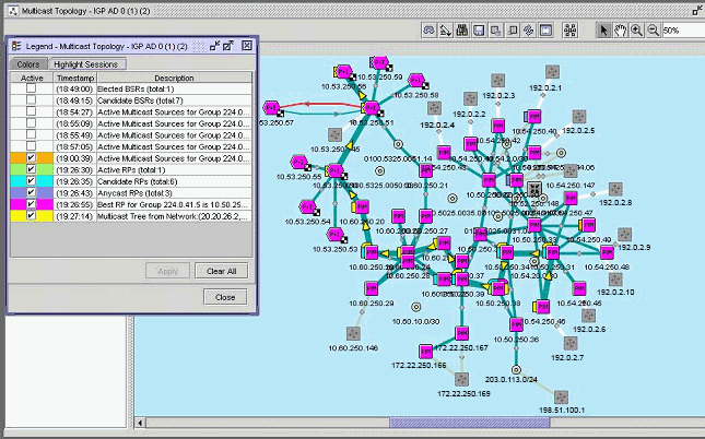
The following figure shows a sample multicast topology view with several highlights.:
Figure 17-2: Sample multicast topology view with highlighting

The CPAM multicast manager displays IGP links with the following colours for PIM links:
Rendezvous point
When a BSR is used, you can retrieve a list of RPs in the network from a router in that domain. When the static RP technique is used, assuming that all of the routers have a consistent configuration, you can retrieve the list of RPs from any router. You can retrieve the CPAM multicast manager RP list for a PIM domain only from the elected BSR.
You can statically define an RP and configure the elected BSR or MSDP. The RP can represent different groups for different configurations. The CPAM creates a global RP object that has different tabs which list different groups for each configuration. An RP in an anycast configuration is the virtual RP and the following information is listed for the RP:
You can identify an RP on the multicast topology view.
Bootstrap router
All BSRs—including candidate BSRs and elected BSR— are available in the PIM Domain. The CPAM creates a global BSR object.
You can identify the candidate BSR and elected BSR routers in the multicast topology highlight.
Multicast states
The CPAM multicast manager can access all of the multicast states in the NFM-P. The CPAM creates a global multicast state object and populates the object when PIM and IGMP (*,G) and (S,G) state objects are created, modified, or deleted. The CPAM uses the global multicast state object to determine the following:
-
the number of (*,G) and (S,G) states that are currently present in the entire network
-
the list of all of the PIM and IGMP routers which have multicast states for a (*,G) or (S,G).
-
the number of PIM or IGMP routers that have multicast states for a (*,G) or (S,G)
-
all of the multicast states in the network without going to all of the multicast routers in the network
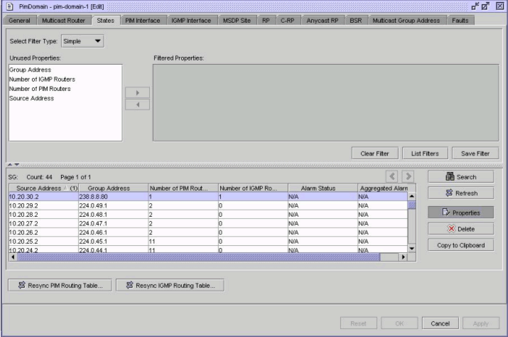
The following figure shows the PIM domain form with the States tab displayed.
Figure 17-3: PIM Domain—Multicast states

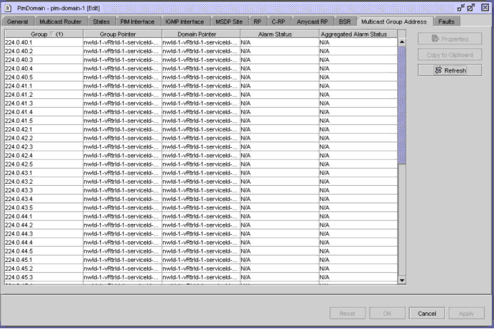
Figure 17-4, PIM Domain—Multicast Group Address shows the PIM domain form with the Multicast Group Address tab displayed.
Figure 17-4: PIM Domain—Multicast Group Address

Active multicast sources
You can use the CPAM multicast manager to highlight the active multicast sources for all of the multicast groups, or for a multicast group, on the multicast topology view.
Multicast tree highlighting
You can use the CPAM multicast manager to highlight the multicast tree on the corresponding multicast topology view for a multicast source and group (S,G) or (*,G) pairs. The highlight can be invoked from multicast topology view where the source S=0.0.0.0 for (*,G). The multicast tree can be within one PIM domain or across multiple PIM domains.
When you perform a multicast tree highlight, the CPAM finds all of the PIM routers and determines all of the outgoing interfaces for that specific (S,G) or (*,G) state. The CPAM then asynchronously highlights the multicast tree—PIM routers and PIM interfaces—on the multicast topology view as it receives responses from the routers.
RP, candidate RP, best RP, and anycast RP highlighting
You can use the CPAM to highlight all of the RPs, the best RP for a group, candidate RPs, and anycast RPs on the multicast topology view. In addition, you can highlight the PIM routers that have a different RP table than the elected BSR. To highlight all of the RPs, the CPAM uses the RP table of the BSR router.
Elected BSR and candidate BSR highlighting
You can use the CPAM to highlight all of the elected and candidate RPs. For candidate RPs, the CPAM uses the CPAM BSR objects. To highlight the elected BSR or BSRs, the CPAM uses both the CPAM BSR objects and existing PIM information from the NFM-P. In addition, you can highlight the PIM routers that have different elected BSRs.
OAM multicast tree highlighting
The multicast trace OAM tool, or mtrace, identifies the hop-by-hop route used by VPRN multicast traffic to reach the target router. This multicast trace OAM diagnostic gathers the hop address, routing error conditions, and packet statistics at each hop. The multicast manager attempts to trace the receiver-to-sender route for the traffic. The destination of the diagnostic can be any PIM-enabled interface in the routing instance. The results of the trace are displayed on the multicast topology view.
You can use the multicast trace OAM to build part of a multicast tree for a (S,G) state from a set of DDRs.
Multicast highlighted path audit
You can use the CPAM to perform a path audit on a highlighted multicast tree or OAM multicast tree. After a path resource audit has been performed, you should examine the ingress queues and Auditing MC-Fabric portions of the Audit Results form to ensure that the multicast network is in good health. The audit fails if these portions have failed or if Ingress Switch Fabric Multicast Path is Secondary or Blackhole.
See Map highlighting overview for information about highlighted path audits. See To perform a highlighted multicast path audit for information about how to configure the multicast highlighted path audit.
Multicast global info tables
You can use the Global Info Tables option on the multicast topology map to view an info table that displays information about PIM interface attributes on the map. When you configure Global Info Tables to display PIM interface statistics information—such as Number of (S,G) States, Number of (*,G) States, Number of (*, *, RP) States, Tx Packets, or Last States Counter Update—you must first ensure that the statistics collection is manually performed on the PIM interface. You can perform an on-demand statistics collection, or a periodic collection by configuring a MIB entry policy.
See To use the Global Info Tables button for information about how to configure Global info tables. See To apply an info table configuration to a map highlight for information about how to apply an info table to a highlight on the multicast topology map.
© 2024 Nokia. Nokia Confidential Information
Use subject to agreed restrictions on disclosure and use.