Workflow to manage MC ring groups
Stages
NE preconfiguration | |
1 |
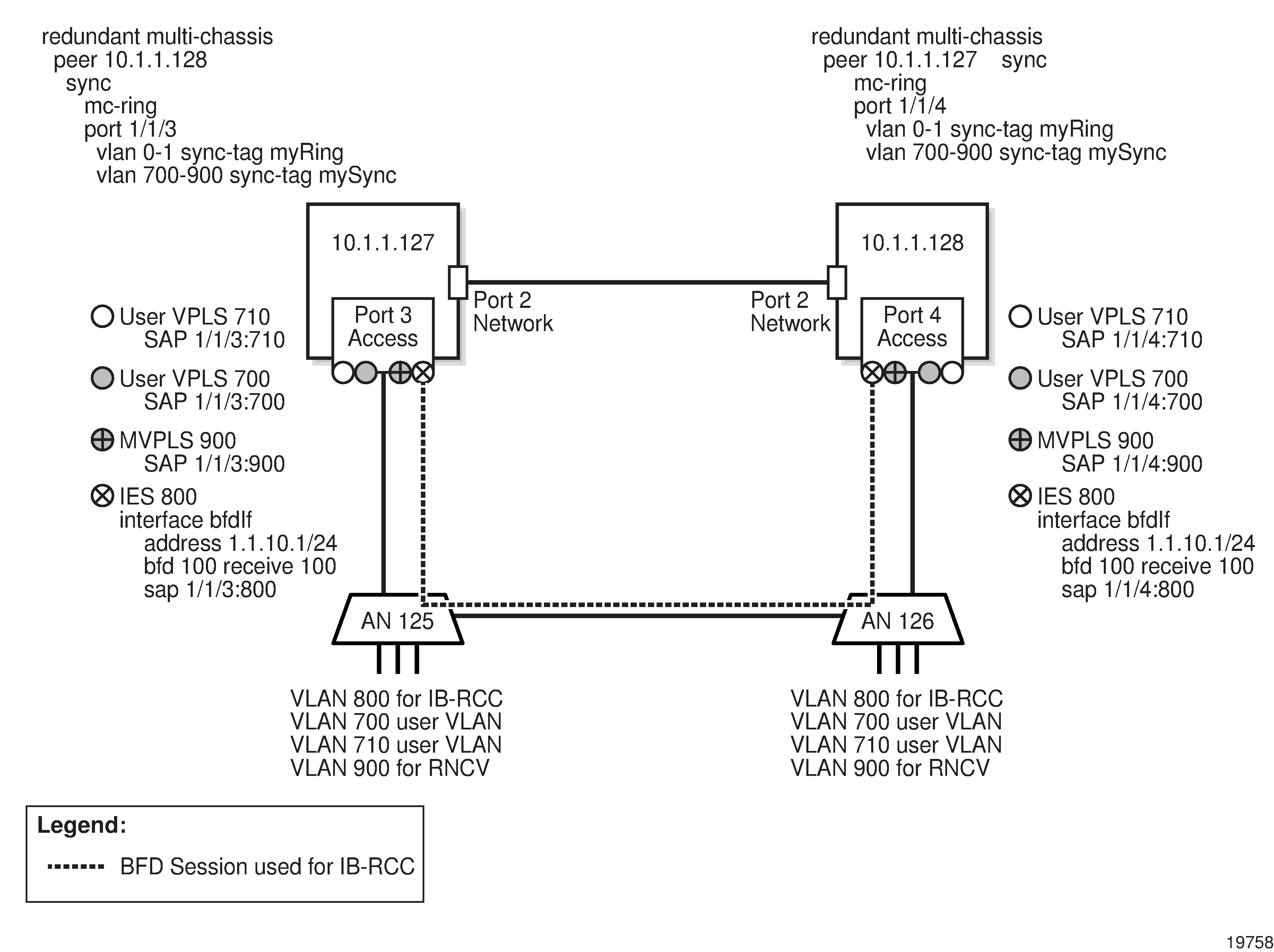
Configure physical connectivity between the two BSAs and the ring nodes, as shown in Figure 45-6, MC ring group preconfiguration . Each port must be operationally up. Figure 45-6: MC ring group preconfiguration
|
2 |
Configure a routing protocol on each BSA to enable IP communication; see Chapter 28, Routing protocol configuration for information about configuring routing protocols. |
3 |
Configure an MVPLS for RNCV on the BSAs; see Chapter 77, VPLS management for information about configuring MVPLS. |
4 |
Create an MC peer group that has the two BSAs as members and has MC ring synchronization enabled; see Chapter 40, MC peer groups for information about MC peer groups. |
5 |
In the MC peer group, create an MC synchronization group that specifies each BSA access port. The MC synchronization group can synchronize the port or a VLAN range. See Chapter 44, MC synchronization groups for information about MC synchronization groups. |
6 |
Configure each ring node with the VLAN tag used for BFD to enable BFD communication through the ring and make each BSA SAP operational. |
MC ring group configuration | |
7 |
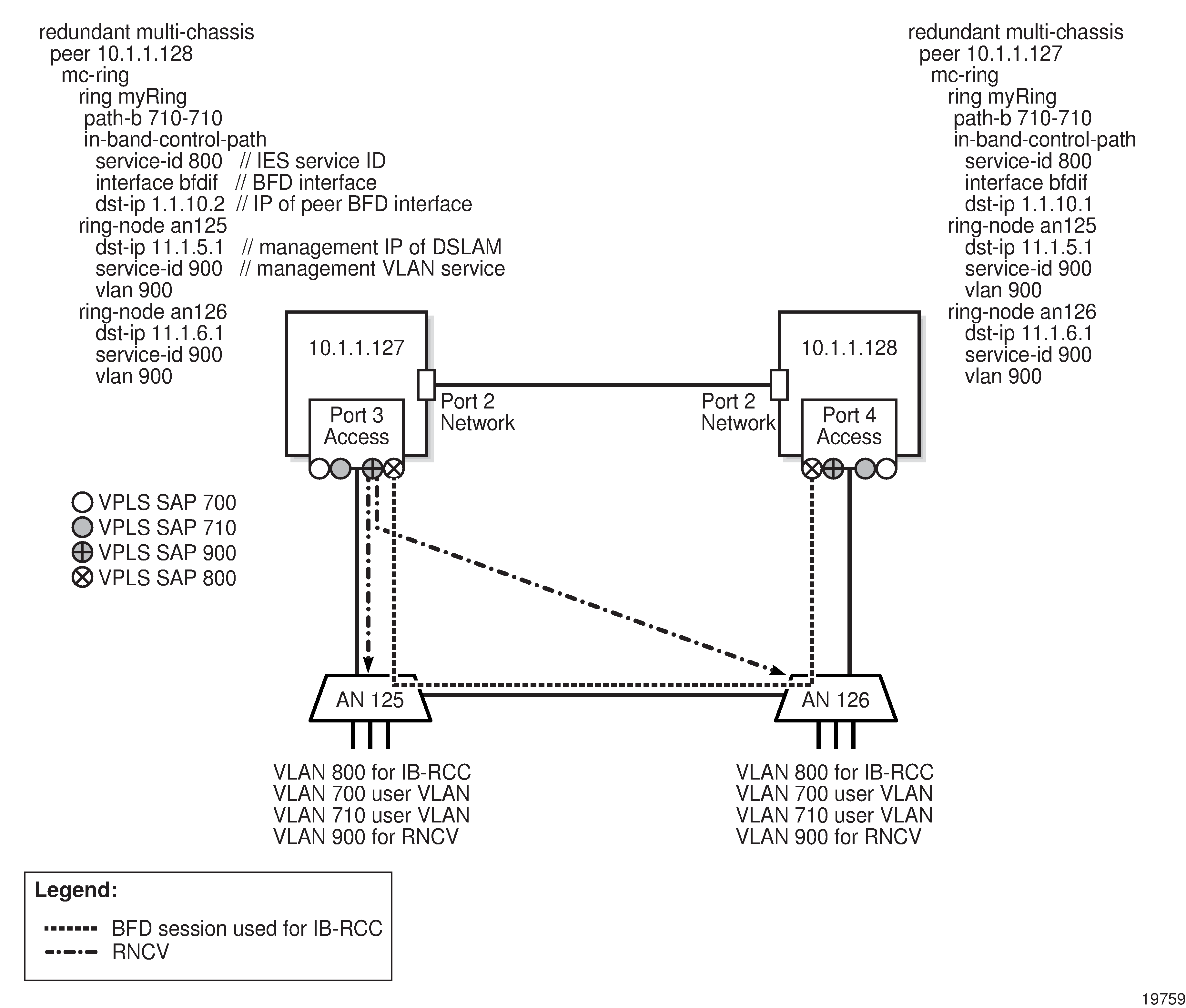
Create an MC ring group that contains the BSAs, which are shown as 10.1.1.127 and 10.1.1.128 in Figure 45-7, MC ring configuration . For each ring node within the ring group, you must specify the management IP address of a ring node as the destination IP address and assign one VLAN for connectivity checking, which is shown in Figure 45-7, MC ring configuration as VLAN 900; see To create an MC ring group for more information. Figure 45-7: MC ring configuration
|
8 |
Create the user VPLS and assign a SAP to each of the two BSA access ports. You can configure a protecting SAP on each BSA to provide SAP-level redundancy, if required; see Chapter 77, VPLS management for information about protecting SAPs. |
9 |
If the VPLS is to send traffic to an IES or a VPRN service, perform the following steps.
|
10 |
If the VPLS is to send traffic to redundant VLL Epipes, perform the following steps.
|
11 |
Turn up the MC ring. At this point, the following statements apply to the Figure 45-7, MC ring configuration configuration.
To test the configuration, you can shut down an access-node port in the ring to break the ring. As a result, the BSA SAPs should remain operationally up, but the operational state of the ring changes to Broken. |