IGP topology overview
Introduction to CPAM IGP topology
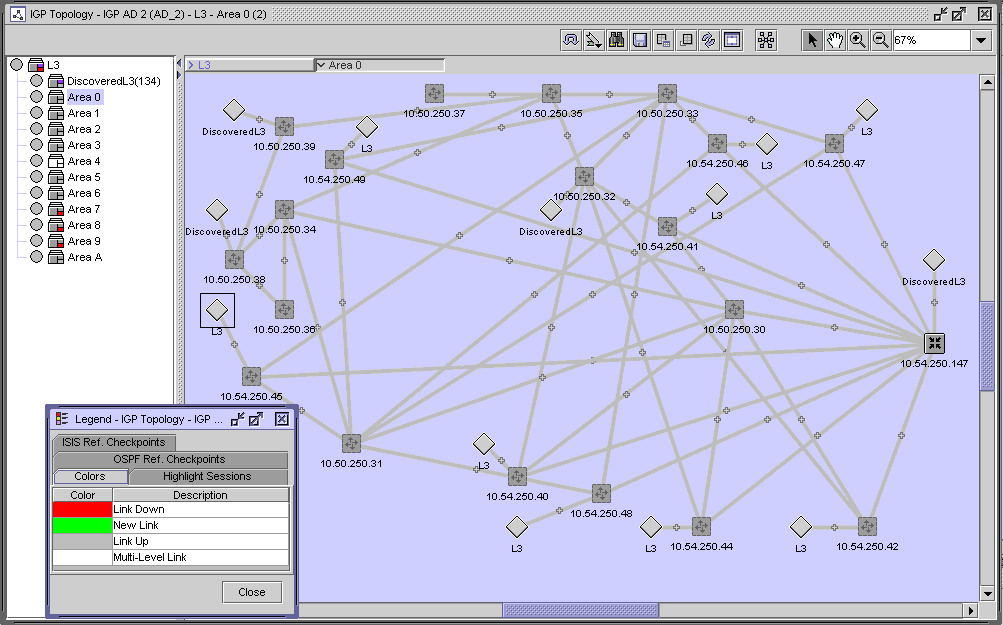
The IGP topology displays a combination of the ISIS and OSPF topologies on a map to provide a complete view of the IGP network. The following figure shows a sample IGP topology.
Figure 4-1: IGP topology

Routers
The following table lists the icons used by the CPAM to identify the roles of the routers in an IGP network.
Table 4-1: Router icons
|
Icon |
IGP and MPLS Router Role |
|---|---|
|
Unmanaged router | |
|
Managed router |
You can navigate directly to a router if the router is being managed by the NFM-P. You can also use the following contextual menu options by right-clicking on the router icon:
-
The Highlight Next Hop menu option opens the Next Hop form for the selected object (managed and unmanaged devices).
-
The Resync menu option specifies that SNMP MIB and CLI information bases are re-read to resynchronize them with the NFM-P, which also resynchronizes the network management settings with the router. Resynchronization does not affect the contents of the historical statistics database or LSDB information (managed devices only).
-
The Equipment Manager option launches the NFM-P equipment manager. The information for the selected managed device is displayed (managed devices only).
-
The NE Sessions option opens a Telnet session, an SSH session, an FTP file browser session, or an SSH file browser session with the selected device (managed devices only).
-
The NE Properties option opens the network element property form for the selected object. This form displays read-only information and configurable parameters (managed devices only).
-
The Properties option opens the router property form for the selected object. This form displays read-only information and configurable parameters.
Devices that are not managed by the NFM-P are displayed with lighter-colored arrow icons than a managed device. There is no contextual menu for unmanaged devices.
Map visualization
Protocol-specific information for an area, level, or router role does not appear on the map when you view a combined topology. The following display conditions are applied to the map for IGP topologies.
-
The router icon displays the NFM-P management status for the router. The icon does not identify the role or ISIS area information for the router.
-
The links are not colored by area or level. A link has a dark green color if it is operationally up, light green when it has been discovered by the system but has not yet had a checkpoint applied to it, red when it has had a checkpoint applied to it but is no longer seen by the system, and white when a group contains links with multiple colors.
-
A circle icon represents OSPF transit networks and ISIS pseudonodes.
Protocols
You can configure several IGP protocols on the same link. The following figure shows an example of OSPF and ISIS running independently on the same link. The IGP map shows all of the links.
Figure 4-2: Multiple IGP links on an interface

Because each link can have another metric, SPF calculations vary depending on the protocol link used by the route. Link selection is specific to the router and varies depending on route policies, protocol weights, and other factors.
In cases where there are multiple protocols on a link, OSPF or ISIS is used in SPF calculations depending on the learned protocol for the destination address, as described in the following table:
Table 4-2: Protocol rules for SPF calculations
|
Protocol at source |
Protocol at destination |
Protocol used in SPF calculation |
|---|---|---|
|
OSPF |
OSPF |
OSPF |
|
ISIS |
ISIS |
ISIS |
|
OSPF/ISIS |
OSPF/ISIS |
OSPF |
|
OSPF |
ISIS |
ISIS |
|
ISIS |
OSPF |
ISIS |
|
OSPF |
OSPF/ISIS |
OSPF |
|
OSPF/ISIS |
ISIS |
ISIS |
|
OSPF/ISIS |
OSPF |
OSPF |
|
ISIS |
OSPF/ISIS |
ISIS |
Dot1 Q and QinQ
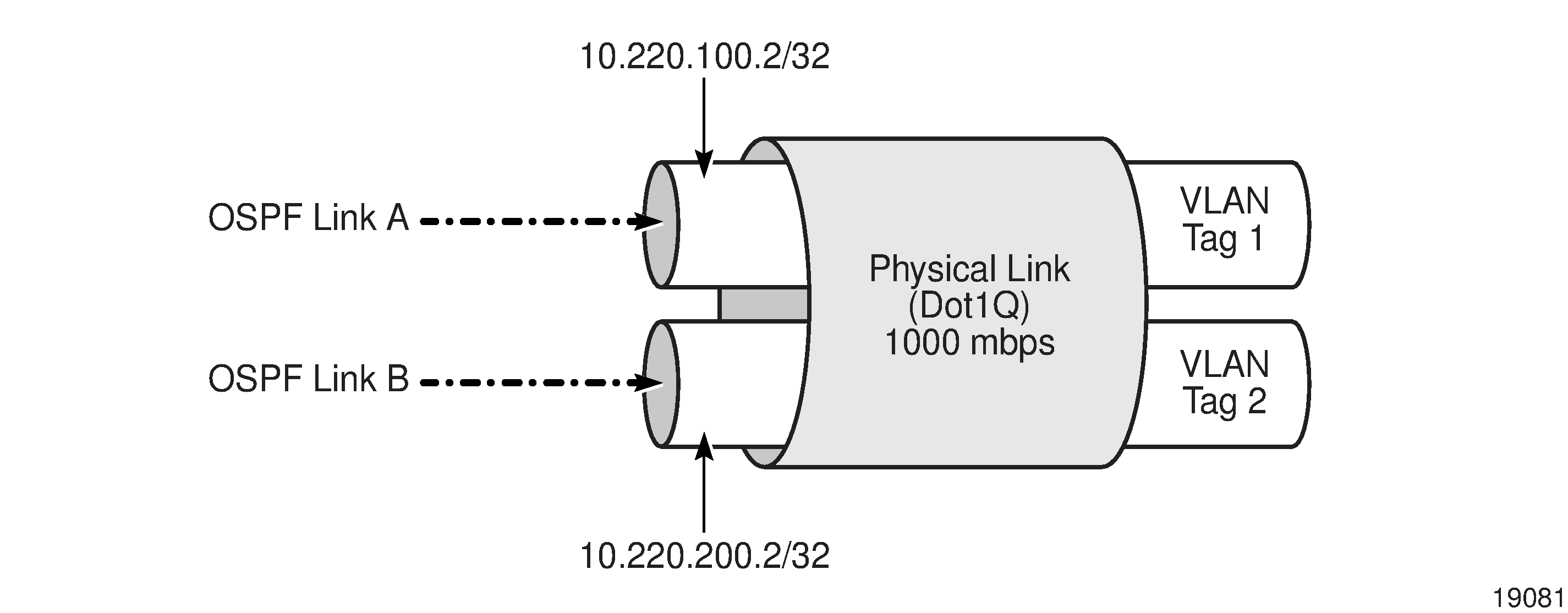
A physical link between two routers can have multiple IGP links when the interface is configured with Dot1Q or QinQ. Each logical link, in the case of Dot1 Q, must have a unique start and end IP address. Each of the logical links can be configured with OSPF, L1 ISIS, and L2 ISIS links.
Each link can advertise a different set of bandwidth parameters when you enable the respective traffic engineering protocol. The bandwidth parameters do not assess other links from the same or different protocols because OSPF and ISIS protocols have no view of the physical layer.
Figure 4-3, Multiple interfaces on the same physical link shows a physical link that is configured to use Dot1 Q with 1000 Mb/s. Two network interfaces are created:
-
Interface A (configured for OSPF)
10.220.100.2/32 using VLAN tag of 1
-
Interface B (configured for OSPF)
10.220.200.2/32 using VLAN tag of 2
Figure 4-3: Multiple interfaces on the same physical link

The example displayed in Figure 4-3, Multiple interfaces on the same physical link also applies to any combination of OSPF and ISIS links running on the same physical link.
The following table lists the bandwidths that are initially advertised by the OSPF-TE protocol.
Table 4-3: Initial bandwidth for links
|
Link |
Available bandwidth (Mb/s) |
|---|---|
|
OSPF Link A |
1000 |
|
OSPF Link B |
1000 |
|
Physical link |
1000 |
The bandwidth for the physical link is reduced to 750 Mb/s if an LSP crossing interface A (10.220.100.2/32) reserves 250 Mb/s of bandwidth. The effective bandwidth is reduced to 750 Mb/s on only OSPF Link A because OSPF-TE has no concept of physical links. The bandwidth is not affected on OSPF Link B. The following table describes the bandwidth that is available on the links:
Table 4-4: Reserved bandwidth for links
|
Link |
Available bandwidth (Mb/s) |
|---|---|
|
OSPF Link A |
750 |
|
OSPF Link B |
1000 |
|
Physical link |
750 |
A system that uses bandwidth and performs bandwidth reservation tasks such as the ABM must be aware of conditions when multiple IGP links traverse the same the physical link.
Non-routed edge discovery
Non-routed edge discovery policies allow you to discover non-routed interfaces and subnets and represent them as adjacencies on the CPAM IGP and MPLS topology maps. A non-routed edge discovery policy requires a specified set of aggregator and edge NEs, and discovers static routes and subnets by using the routing interfaces of the specified NEs. See To configure a non-routed edge discovery policy for more information about configuring a non-routed edge discovery policy.
© 2024 Nokia. Nokia Confidential Information
Use subject to agreed restrictions on disclosure and use.