NFM-P multihoming
Overview
The NFM-P server and NFM-P auxiliary collector components of the application communicate with very different entities: a managed network, a collection of clients (GUIs and XML API), and between each other. Since the entities may exist in very different spaces, Nokia recognizes the importance of separating these different types of traffic. Nokia therefore supports configuring the NFM-P server and NFM-P auxiliary such that it uses different network interfaces (IP addresses) to manage the network and to service the requirements of the NFM-P clients.
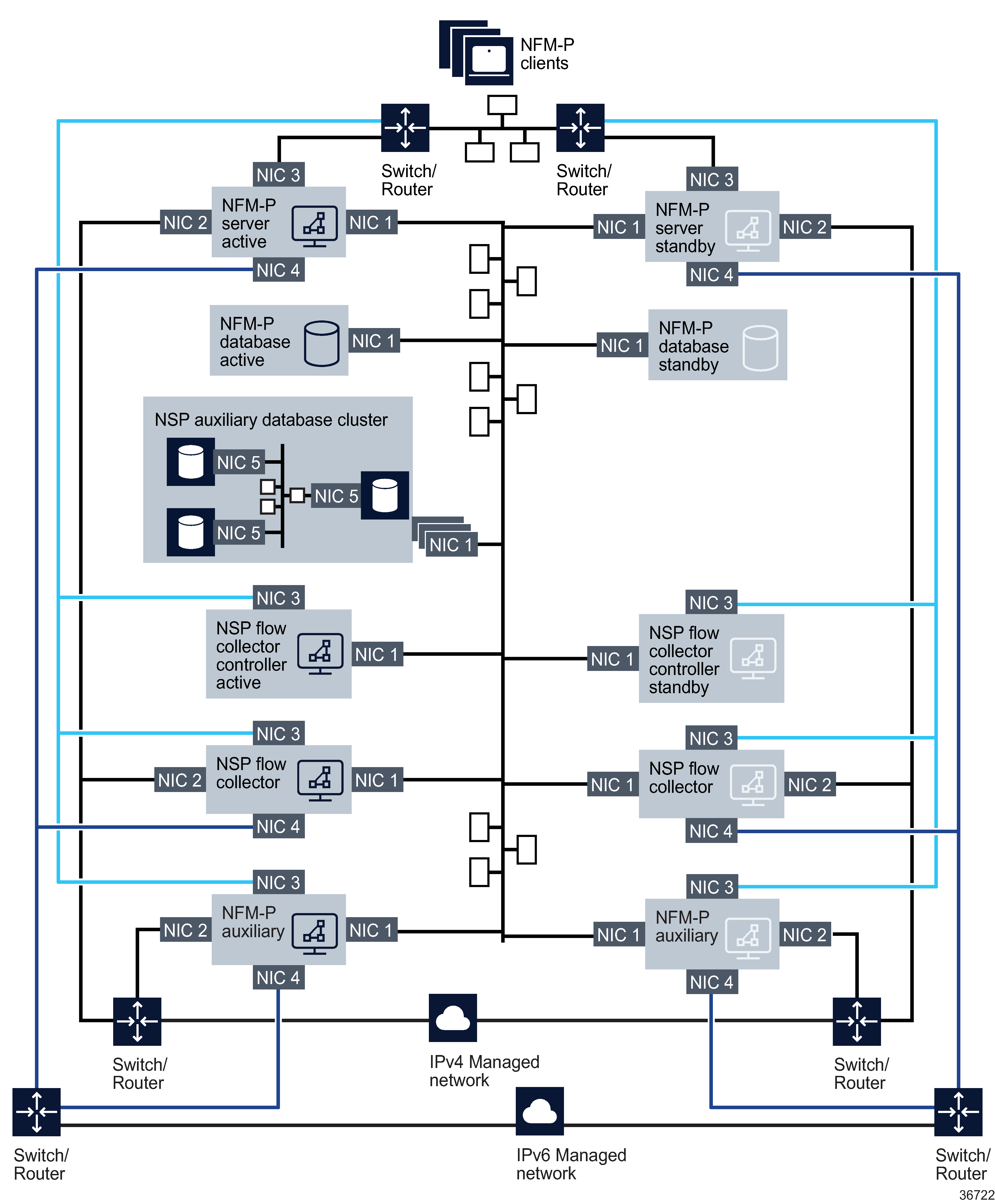
The NFM-P server uses an internal communications system (JGroups/JMS) to handle bi-directional access to the NFM-P server for the NFM-P clients and the NFM-P auxiliary collectors. In NFM-P, this communication system can be configured to allow the NFM-P clients and NFM-P auxiliary collectors to communicate using different network interfaces on the NFM-P server. This adds significant flexibility when isolating the different types of traffic to the NFM-P server. If using this mode, special attention must be paid to the firewall rules on the network interfaces on the NFM-P server and NFM-P auxiliary collectors (NICs 1 and NICs 3 on Figure 7-3, Distributed NFM-P server/database deployment with multiple network interfaces).
It is a security requirement that all IP communications from an NFM-P auxiliary collector to the NFM-P main server use only one IP address. This IP Address must be the same IP address as the auxiliary collector IP address configured when installing the main server. Any other IP communications originating from a different IP address on the auxiliary collector will be rejected by the NFM-P main server.
When installing NFM-P components on stations with multiple interfaces, each interface must reside on a separate subnet, with the exception of interfaces that are to be used in IP Bonding.
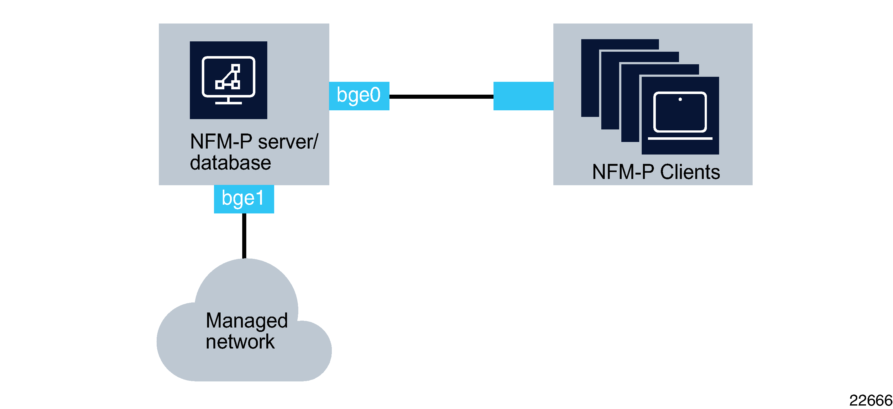
Figure 7-2, Collocated NFM-P server/database deployment with multiple network interfaces illustrates a collocated NFM-P server/database deployment where the NFM-P is configured to actively use more than one network interface.
It is not necessary to use the first network interface on the NFM-P server station (for example ce0, bge0) to communicate with the NFM-P GUI clients.
Figure 7-2: Collocated NFM-P server/database deployment with multiple network interfaces

Figure 7-3: Distributed NFM-P server/database deployment with multiple network interfaces

Figure 7-3, Distributed NFM-P server/database deployment with multiple network interfaces illustrates a distributed, redundant NFM-P deployment where the NFM-P components are configured to actively use more than one network interface.
Due to limitations with the inter-process and inter-station communication mechanisms, a specific network topology and the use of hostnames is required (see Use of hostnames for the NFM-P client). Contact an Nokia representative to obtain further details.
NFM-P server multiple IP addresses deployment scenarios
The NFM-P server supports the configuration of different IP addresses for the following purposes:
-
One or multiple network interfaces can be used to manage the network. (NIC 2 on Figure 7-3, Distributed NFM-P server/database deployment with multiple network interfaces) This network interface contains the IP address that the managed devices will use to communicate with the NFM-P server and NFM-P auxiliary. If managing a network element with both an in-band and out-of-band connection, the same network interface on the NFM-P server must be used for both communication types.
-
One network interface can be used to service the requirements of the NFM-P clients (GUIs and XML API) (NIC 3 on Figure 7-3, Distributed NFM-P server/database deployment with multiple network interfaces). This network interface contains the IP address that all clients (GUIs and XML API) will use to communicate with the NFM-P server. All clients (GUIs and XML API) must be configured to use the same IP address to communicate to the NFM-P server. This IP address can be different from the one used by the managed devices to communicate with the NFM-P server. Each client can use the hostname to communicate with the NFM-P server, where the hostname could map to different IP addresses on the NFM-P server - for example, some clients could connect over IPv4 and some over IPv6. In this scenario, the NFM-P server must be configured for clients to use hostname and not IP.
-
One network interface can be used to communicate with the NFM-P database, NSP auxiliary database, and NFM-P auxiliary collectors as well as any redundant NFM-P components should they be present (NIC 1 on Figure 7-3, Distributed NFM-P server/database deployment with multiple network interfaces). This network interface contains the IP address that the NFM-P database, NSP auxiliary database, and redundant NFM-P components will use to communicate with the NFM-P server. This IP address can be different from the addresses used by the NFM-P clients and the managed devices to communicate with the NFM-P server.
-
In a redundant NFM-P installation, the NFM-P servers and NFM-P auxiliary collectors must have IP connectivity to the NFM-P server peer.
-
Additional network interfaces may be configured on the NFM-P server station, at the customer’s discretion, to perform maintenance operations such as station backups.
-
IPv4 and IPv6 network elements can be managed from the same interface or from separate interfaces. (NIC2 and/or NIC4 on Figure 7-3, Distributed NFM-P server/database deployment with multiple network interfaces).
NFM-P auxiliary statistics collector multiple IP addresses deployment scenarios
The NFM-P auxiliary statistics collector supports the configuration of different IP addresses for the following purposes:
-
One or multiple network interfaces can be used to retrieve information from the managed network. (NIC 2 on Figure 7-3, Distributed NFM-P server/database deployment with multiple network interfaces) This network interface contains the IP address that the managed devices will use to retrieve the accounting statistics files, and performance statistics from the network elements.
-
One network interface can be used to service the requirements of the XML API clients (NIC 3 on Figure 7-3, Distributed NFM-P server/database deployment with multiple network interfaces). This network interface contains the IP address that all XML API clients will use to communicate with the NFM-P auxiliary statistics collector. XML API clients will use this IP address to retrieve the logToFile statistics collection data from the NFM-P auxiliary statistics collector.
-
One network interface can be used to communicate with the NFM-P server, NFM-P database, NSP auxiliary database cluster as well as any redundant NFM-P components should they be present (NIC 1 on Figure 7-3, Distributed NFM-P server/database deployment with multiple network interfaces). This network interface contains the IP address that the NFM-P server, NFM-P database, NSP auxiliary database, and redundant NFM-P components will use to communicate with the NFM-P auxiliary statistics collector. This IP address can be different from the addresses used by the NFM-P XML API clients and the managed devices to communicate with the NFM-P auxiliary statistics collector.
-
In a redundant NFM-P installation, the NFM-P auxiliary statistics collector must have IP connectivity to the NFM-P server peer.
-
Additional network interfaces may be configured on the NFM-P auxiliary statistics collector station, at the customer’s discretion, to perform maintenance operations such as station backups.
-
IPv4 and IPv6 network elements can be managed from the same interface or from separate interfaces. (NIC2 and/or NIC4 on Figure 7-3, Distributed NFM-P server/database deployment with multiple network interfaces).