Internet Enhanced Service
This chapter provides information about Internet Enhanced Services (IES), the process overview, and implementation notes.
IES overview
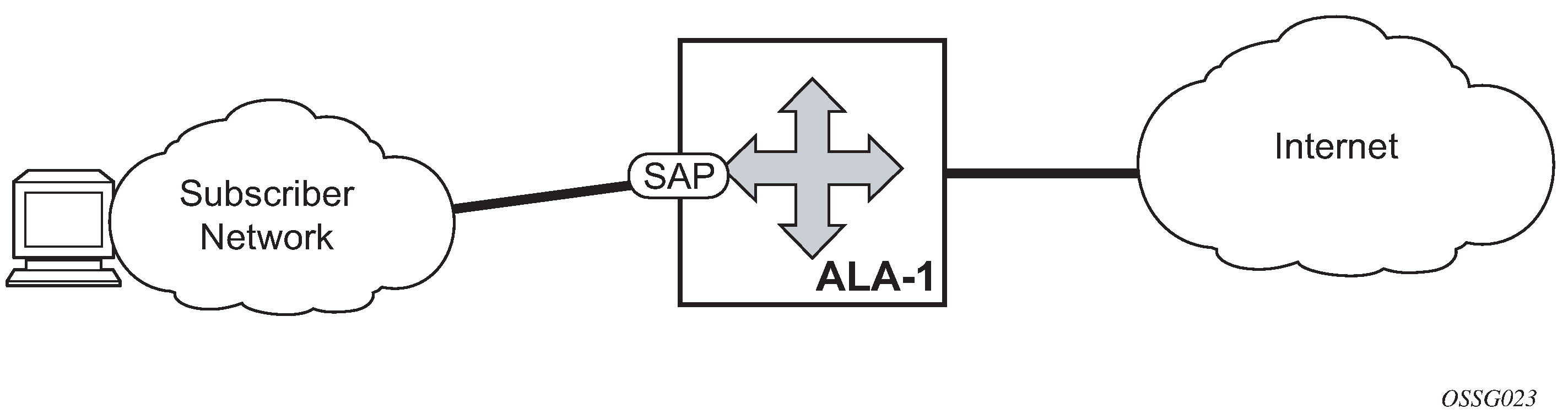
IES is a routed connectivity service where the subscriber communicates with an IP router interface to send and receive Internet traffic. An IES has one or more logical IP routing interfaces, each with a SAP that acts as the access point to the subscriber network.
IES allows IP interfaces to participate in the same routing instance used for service network core routing connectivity. IES services require that the IP addressing scheme used by the subscriber be unique between other provider addressing schemes and potentially the entire Internet. While IES is part of the routing domain, the usable IP address space may be limited. This allows a portion of the service provider address space to be reserved for service IP provisioning, and be administered by a separate, but subordinate address authority.
IP interfaces defined within the context of an IES service must have a SAP associated as the uplink access point to the subscriber network. Multiple IES services are created to segregate subscriber-owned IP interfaces as shown in the following figure.
In addition to in-band management connectivity, the IES service supports the following features:
-
Multiple IES services are created to separate IP interfaces.
-
More than one IES service can be created for a single customer ID.
-
More than one IP interface can be created within a single IES service ID. All IP interfaces created within an IES service ID belong to the same customer.
IES features
This section describes various general service features and any special capabilities or considerations as they relate to IES services.
IP interfaces
IES customer IP interfaces can be configured with most of the same options found on the core IP interfaces. The advanced configuration options supported are:
-
VRRP - for IES services with more than one IP interface
-
Cflowd
-
Secondary IP addresses
-
ICMP Options
Configuration options found on core IP interfaces not supported on IES IP interfaces are:
MPLS forwarding
NTP broadcast receipt
Object grouping and state monitoring
This feature introduces a generic operational group object which associates different service endpoints (pseudowires and SAPs) located in the same or in different service instances. The operational group status is derived from the status of the individual components using specific rules specific to the application using the concept. A number of other service entities, the monitoring objects, can be configured to monitor the operational group status and to perform specific actions as a result of status transitions. For example, if the operational group goes down, the monitoring objects are brought down.
IES IP interface applicability
This concept is used by an IPv4 IES interface to affect the operational state of the IP interface monitoring the operational group. Individual SAP and spoke SDPs are supported as monitoring objects.
The following rules apply:
An object can only belong to one group at a time.
An object that is part of a group cannot monitor the status of a group.
An object that monitors the status of a group cannot be part of a group.
An operational group may contain any combination of member types, SAP, or spoke SDPs.
An operational group may contain members from different VPLS service instances.
Objects from different services may monitor the operational group.
There are two steps involved in enabling the functionality:
Identify a set of objects whose forwarding state should be considered as a whole group, then group them under an operational group using the oper-group command.
Associate the IP interface to the operational group using the monitor-oper-group command.
The status of the operational group is dictated by the status of one or more members according to the following rules:
The operational group goes down if all the objects in the operational group go down. The operational group comes up if at least one component is up.
An object in the group is considered down if it is not forwarding traffic in at least one direction. That could be because the operational state is down or the direction is blocked through some validation mechanism.
If a group is configured but no members are specified yet, then its status is considered up.
As soon as the first object is configured the status of the operational group is dictated by the status of the provisioned members.
The following configuration shows the operational group g1, the VPLS SAP that is mapped to it and the IP interfaces in IES service 2001 monitoring the operational group g1. This example uses an R-VPLS context.
Operational group g1 has a single SAP (1/1/1:2001) mapped to it and the IP interfaces in the IES service 2001 derive its state from the state of operational group g1.
MD-CLI
In the MD-CLI, the VPLS instance includes the name v1. The IES interface links to the VPLS using the vpls command option.
[ex:/configure service]
A:admin@node-2# info
    oper-group "g1" {
    }
    ies "2001" {
        customer "1"
        interface "i2001" {
            monitor-oper-group "g1"
            vpls "v1" {
            }
            ipv4 {
                primary {
                    address 192.168.1.1
                    prefix-length 24
                }
            }
        }
    }
    vpls "v1" {
        admin-state enable
        service-id 1
        customer "1"
        routed-vpls {
        }
        stp {
            admin-state disable
        }
        sap 1/1/1:2001 {
            oper-group "g1"
            eth-cfm {
            mep md-admin-name "1" ma-admin-name "1" mep-id 1 {
            }
        }
        sap 1/1/2:2001 {
        }
        sap 1/1/3:2001 {
        }
    }
classic CLI
In the classic CLI, the VPLS instance includes the allow-ip-int-bind and the name v1. The IES interface links to the VPLS using the vpls command option.
A:node-2>config>service# info
----------------------------------------------
        oper-group "g1" create
        exit
        vpls 1 name "v1" customer 1 create
            allow-ip-int-bind
            exit
            stp
                shutdown
            exit
            sap 1/1/1:2001 create
                oper-group "g1"
                eth-cfm
                    mep 1 domain 1 association 1 direction down
                    ccm-enable
                no shutdown
            exit
            sap 1/1/2:2001 create
                no shutdown
            exit
            sap 1/1/3:2001 create
                no shutdown
            exit
            no shutdown
        exit
        ies 2001 name "2001" customer 1 create
            shutdown
            interface "i2001" create
                monitor-oper-group "g1"
                address 192.168.1.1/24
                vpls "v1"
                exit
            exit
        exit
SAPs
This section provides information about SAPs.
Encapsulations
The following SAP encapsulations are supported on IES services:
Ethernet null
Ethernet dot1q
Encapsulation
The packet is encapsulated on an Ethernet pseudowire, which is associated with a pseudowire port on the converged PE, and a spoke SDP on the access PE. The SDP could use an LDP LSP, RSVP LSP, segment routed tunnel, BGP RFC 8277 tunnel, or LDP over RSVP tunnel. Hash labels are not supported. The SDP may be bound to a port or a LAG, although shaping Vports for pseudowire ports on LAGs in distributed mode is not supported. If an SDP is rerouted, then the corresponding pseudowire ports are brought operationally down. Pseudowire ports are associated with an SDP by configuration.
Shaping and bandwidth control
Pseudowire SAPs can be shaped on egress by a Vport on a physical port. The pseudowire SAP egress cannot explicitly declare which Vport to use, but they inherit the Vport used by the PW port egress shaping.
The intermediate destination identifier, used for ESM on MPLS pseudowires, is not applicable to VLL, IES, and VPRN pseudowire SAPs.
If a pseudowire port is configured on a LAG, Vport shaping is only supported if the LAG is in link mode.
Per-access node shaping is configured as follows:
Configure a Vport per AN under the port (or LAG) to which the SDP corresponding to the pseudowire SAP is bound. Use the rate command option in the following context to configure the Vport with an aggregate rate-limit:
- MD-CLI
configure port ethernet access egress virtual-port aggregate-rate - classic
CLI
configure port ethernet access egress vport agg-rate-limit
- MD-CLI
Explicitly assign (by static configuration) a pseudowire port to a Vport. For limiting the total traffic to an AN, all pseudowire ports for an AN-port would refer to the same Vport.
For bandwidth control per pseudowire, the following configuration steps are used:
Create multiple Vports under the port to which SDP is bound. Each Vport can be configured with an aggregate rate limit, a scheduler, or a port scheduler.
Assign each pseudowire to an AN to a unique Vport shaper (regular IOM/MDA).
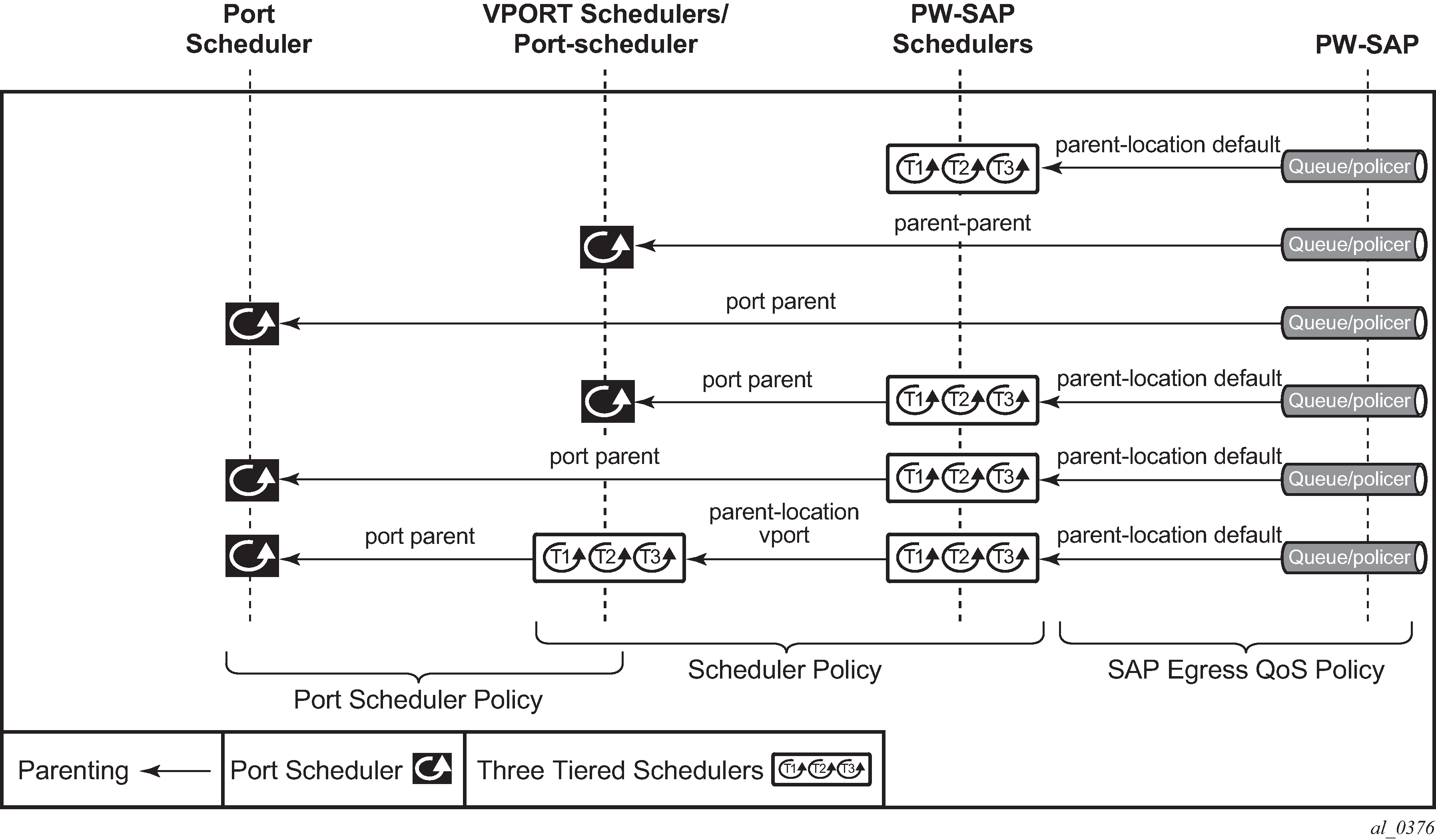
To configure the aggregate rate limit or port scheduler under a Vport, PW SAP queues and schedulers must be configured with the port-parent command.
To make use of a scheduler under a Vport, PW SAP schedulers must be configured with a parent command and the parent-location vport under tier 1 of the scheduler policy. The egress hierarchical parenting relationship options are shown in PW SAP egress scheduling hierarchy options. See the 7705 SAR Gen 2 Quality of Service Guide Quality of Service guide for more information.
Lag considerations
PW ports may be bound to Vport schedulers bound to a LAG. However, if the LAG is configured in distributed mode, then bandwidth is shared according to the active LAG members across a single IOM. If the LAG spans multiple IOMs, then it effectively operates in link mode across the IOMs. That is, the full LAG bandwidth is allocated to the LAG members on each IOM. Therefore, the use of a Vport on a distributed mode LAG with a port scheduler on the port or Vport and PW SAPs is explicitly not supported and is not a recommended configuration. It is recommended that port-fair mode is used instead.
Last mile packet size adjustment
In the application where pseudowire SAPs are used to apply access QoS for services aggregated from an Ethernet access network, MPLS labels may not be present on the last-mile and link from an access node. In these cases, policers, queues, and H-QoS schedulers should account for packets without MPLS overhead, modeled as ‟encaps-offset”. Vport and port schedulers behave as per the table below. In the datapath, the actual pseudowire encap overhead (taking into account the MPLS labels) added to the packet is tracked, and may be applied to the scheduler calculations via the configured packet byte offset.
The rate limit configured for the pseudowire SAP accounts for subscriber or service frame wire rate: without MPLS overhead and including the last mile overhead (unless a packet byte offset is configured).
Packet sizes used for pseudowire SAPs summarizes the default packet sizes used at each of the schedulers on the IOM/Ethernet MDA, assuming a 1000 byte customer packet.
| Type | Size |
|---|---|
exp-secondary-shaper |
20B preamble + 26 MPLS + 1000B pkt |
port-scheduler rate |
20B preamble + 1000B pkt |
regular queue/policer rate |
1000B pkt |
vport agg-limit-rate |
20B preamble + 1000B pkt |
vport port-scheduler rate |
20B preamble + 1000B pkt |
vport scheduler rate |
1000B pkt |
vport scheduler to port-scheduler rates |
20B preamble + 1000B pkt |
Redundancy with pseudowire SAPs
This section describes a mechanism in which one end on a pseudowire (the "master") dictates the active PW selection, which is followed by the other end of the PW (the 'standby'). This mechanism and associated terminology is specified in RFC6870.
Within a chassis, IOM and port based redundancy is based on active/backup LAG. The topology for the base MPLS LSP used by the SDP could be constrained such that it could get re-routed in the aggregation network, but would always appear on the LAG ports on the Layer 3 PE. In the case that the tunnel is re-routed to a different port, the MPLS pseudowire SAPs would be brought down.
To provide Layer 3 PE redundancy, dual homing of the access PE into separate Layer 3 PEs using active/standby pseudowire status is supported. This is shown in Dual homing into multiple Layer 3 PEs.
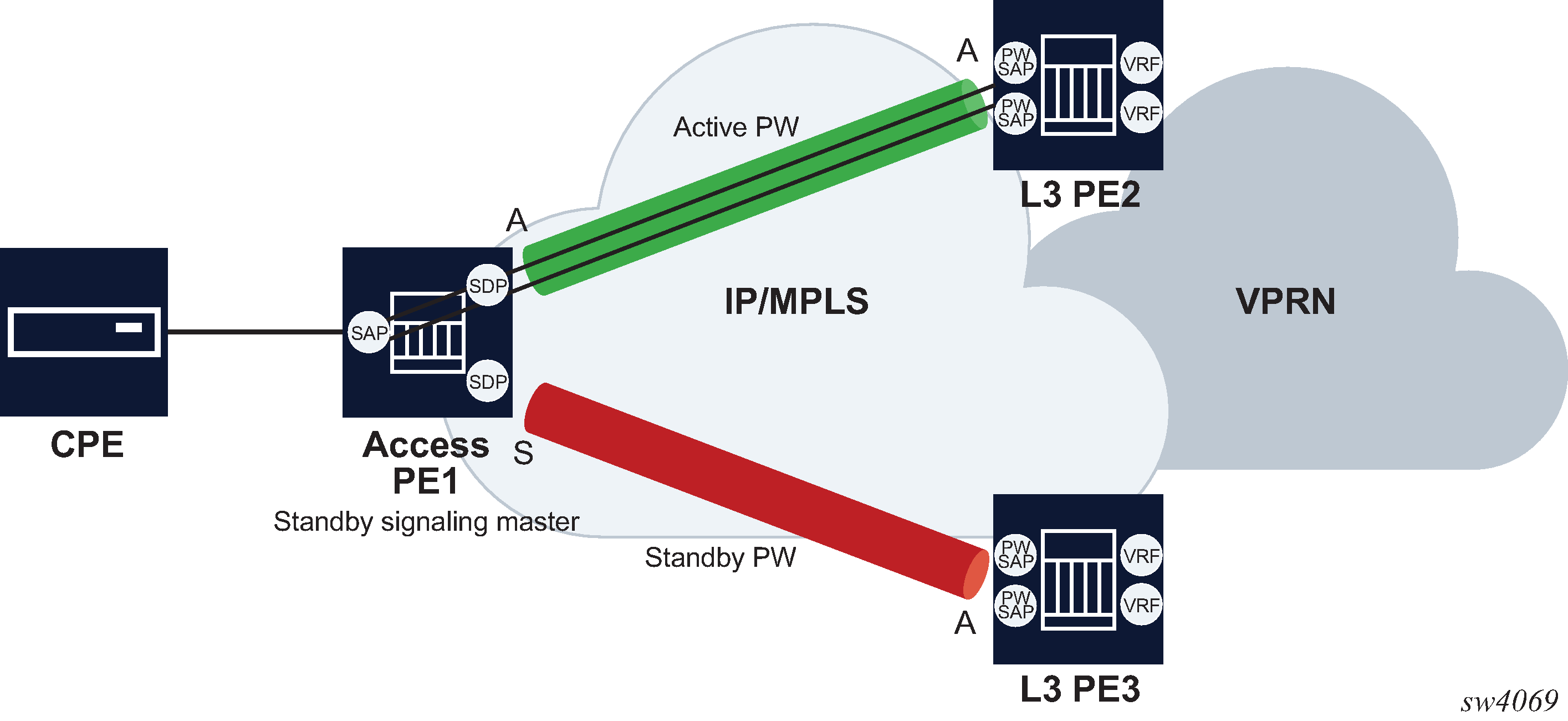
Dual homing operates in a similar manner to Spoke-SDP termination on IES/VPRN. Dual homing into multiple Layer 3 PEs displays the access PE is dual-homed to the Layer 3 PEs using two spoke-SDPs. Use the following command to configure the endpoint in the access PE to be the master from a pseudowire redundancy perspective:
- MD-CLI
configure service epipe endpoint standby-signaling master - classic
CLI
configure service epipe endpoint standby-signaling-master
The access PE picks one of the spoke SDPs to make active, and one to make standby, based on the local configuration of primary or spoke SDP precedence.
The pseudowire port at the Layer 3 PE behaves as a standby from the perspective of pseudowire status signaling. That is, if its peer signals ‟PW FWD standby (0x20)” status bit for the specific Spoke-SDP and the local configuration does not allow this bit to be ignored, the PE takes the pseudowire port to a local operationally down state. This is consistent with the Spoke-SDP behavior for the case of Spoke-SDP termination on IES/VPRN.
As a consequence, all of the pseudowire SAPs bound to the pseudowire port are taken down, which causes the corresponding IES or VPRN interface to go to a local operationally down state and therefore stops forwarding packets toward this pseudowire port.
Conversely, the formerly standby pseudowire is made active and then the corresponding pseudowire port on the second Layer 3 PE is taken locally operationally up. Therefore, all of the pseudowire SAPs bound to the pseudowire port are brought up, which causes the corresponding IES or VPRN interface to go to a local operationally up state allowing forwarding of packets toward this pseudowire port.
For VLLs, a PW port always behaves as a standby from the perspective of PW redundancy. This is because the PW port is taken locally operationally down if any non-zero PW status (including a PW Preferential Forwarding status of standby) is received. Master-standby PW redundancy mechanisms for dual homing of the access PE into separate converged PEs using active or standby PW status are supported as shown in Master-standby PW redundancy . However, this is only applicable to VLL services consisting of only SAPs, PW-SAPs, or spoke-SDPs. Dual-homing redundancy, taking into account the status of the PW SAP, is not supported where a PBB tunnel between the two converged PEs exists in the Epipe VLL service.

As in the existing implementation, standby signaling is configured to master on the spoke SDP at the access PE. However, explicit configuration of standby signaling to the standby on the PW port is not required, as this is the default behavior.
The forwarding behavior is the same as when standby-signaling is configured to standby for Epipe spoke SDPs. That is, when enabled, if a PW Forwarding Standby (0x20) LDP status message is received for the P11111111W, then the transmit direction is blocked for the PW port. All PW SAPs bound to the corresponding PW port are treated from a SAP OAM perspective in the same manner as a fault on the service, such as an SDP-binding down or remote SAP down.
PW redundancy with multiple active/standby PW ports or PW SAPs bound to the same Ethernet SAP in the converged PE is not supported. The independent mode of operation for PW redundancy is not also supported for a PW port.
Operational group support for PW ports
A PW port state may be linked to the state of an operational group, such that if the operational group goes down, the SDP binding for the PW port also goes operationally down, and therefore the corresponding PW status bit signaled (0x00000001 - Pseudowire Not Forwarding). If a status of 0x00000001 is signaled for a currently active PW, and active/standby dual homing is in use then the access PE fails over to the standby PW to the standby converged PE.
This is achieved by linking an SDP binding to an operational group for PW SAPs belonging to any supported service types (including those with group interfaces) bound to that PW port, such as IES, VPRN, or Epipe VLL.
Associate an operational group at the SDP binding level (MD-CLI)
[ex:/configure service]
A:admin@node-2# info
    sdp 1 {
        }
        pw-port {
            binding-port 1/1/1
        }
    }

[ex:/configure pw-port 1 sdp 1]
A:admin@node-2# info
    admin-state enable
    vc-id 11
    monitor-oper-group "test-oper-grp"
Associate an operational group at the SDP binding level (classic CLI)
A:node-2>config>service# info
----------------------------------------------
      sdp 1 create
            no shutdown
            binding
                port 1/1/1
                pw-port 1 vc-id 11 create
                    no shutdown
                    monitor-oper-group "test-oper-grp"
                exit
            exit
        exit
The monitor-oper-group command specifies the operational group to be monitored by the PW-Port under which it is configured. The operational group name must be already configured under the configure service context before its name is referenced in this command.
The following illustrates how a PW port can track the status of VPRN uplinks using monitor-oper-group.
Uplinks in a VPRN may be monitored using a BFD session on the network facing IP interfaces in a VPRN or on the network IP interfaces supporting the uplinks.
Configure an operational group to monitor the BFD session (MD-CLI)
[ex:/configure service]
A:admin@node-2# info
    oper-group "test-oper-grp" {
        bfd-liveness {
            router-instance "105"
            interface-name "vprn-if"
            dest-ip 10.0.0.20
        }
    }
Configure an operational group to monitor the BFD session (classic CLI)
A:node-2>config>service# info
----------------------------------------------
         oper-group "test-oper-grp" create
            bfd-enable interface "vprn-if" dest-ip 10.0.0.20 service 105
Alternatively, the state of network interfaces can be monitored as follows.
Configure the monitoring of network interfaces (MD-CLI)
[ex:/configure service]
A:admin@node-2# info
    oper-group "test-oper-grp" {
        bfd-liveness {
            interface-name "network-if"
            dest-ip 10.0.1.20
        }
    }
Configure the monitoring of network interfaces (classic CLI)
A:node-2>config>service# info
----------------------------------------------
         oper-group "test-oper-grp" create
            bfd-enable interface "network-if" dest-ip 10.0.1.20
The PW port is then configured with monitor-oper-group as follows.
Configure the PW port with the monitor-oper-group option (MD-CLI)
[ex:/configure service]
A:admin@node-2# info
    sdp 1 {
        }
        pw-port {
            binding-port 1/1/2
        }
    }

[ex:/configure pw-port 100 sdp 1]
A:admin@node-2# info
    vc-id 25
    monitor-oper-group "test-oper-grp"
Configure the PW port with the monitor-oper-group option (classic CLI)
A:node-2>config>service>sdp>binding# info
----------------------------------------------
            port 1/1/2
            pw-port 100 vc-id 25 create
                shutdown
                monitor-oper-group "test-oper-grp"
            exit
----------------------------------------------
Routing protocols
The IES IP interfaces are restricted as to the routing protocols that can be defined on the interface based on the fact that the customer has a different routing domain for this service. The IES IP interfaces support the following routing protocols:
RIP
OSPF
IS-IS
BGP
IGMP
PIM
CPE connectivity check
Static routes are used within many IES services. Unlike dynamic routing protocols, there is no way to change the state of routes based on availability information for the associated CPE. CPE connectivity check adds flexibility so that unavailable destinations are removed from the service provider routing tables dynamically and minimize wasted bandwidth.
The availability of the far-end static route is monitored through periodic polling. The polling period is configured. If the poll fails a specified number of sequential polls, the static route is marked as inactive.
An ICMP ping mechanism is used to test the connectivity. If the connectivity check fails and the static route is deactivated, the router continues to send polls and reactivate any routes that are restored.
QoS policies
When applied to IES services, service ingress QoS policies only create the unicast queues defined in the policy. The multipoint queues are not created on the service. With IES services, service egress QoS policies function as with other services where the class-based queues are created as defined in the policy. Both Layer 2 or Layer 3 criteria can be used in the QoS policies for traffic classification in an IES.
Filter policies
Only IP filter policies can be applied to IES services.
MPLS hash label
The router supports the Flow Aware Transport label, known as the hash label (RFC 6391). LSR nodes in a network can load-balance labeled packets in a more granular way than by hashing on the standard label stack. See the 7705 SAR Gen 2 MPLS Guide for more information.
The hash label is supported for Epipe and Ipipe spoke SDP termination on IES services. Configure it using the hash-label command in the spoke-sdp context for an IES interface context.
Spoke SDPs
Distributed services use service destination points (SDPs) to direct traffic to another router through service tunnels. SDPs are created on each participating router and then bound to a specific service. SDP can be created as either GRE or MPLS. See the 7705 SAR Gen 2 Services Overview Guide for information about configuring SDPs.
This feature provides the ability to cross-connect traffic entering on a spoke SDP, used for Layer 2 services (VLLs or VPLS), on to an IES or VPRN service. From a logical point of view, the spoke SDP entering on a network port is cross-connected to the Layer 3 service as if it entered by a service SAP. The main exception to this is traffic entering the Layer 3 service by a spoke SDP is handled with network QoS policies and not access QoS policies.
SDP-ID and VC label service identifiers depicts traffic terminating on a specific IES or VPRN service that is identified by the SDP-ID and VC label present in the service packet.
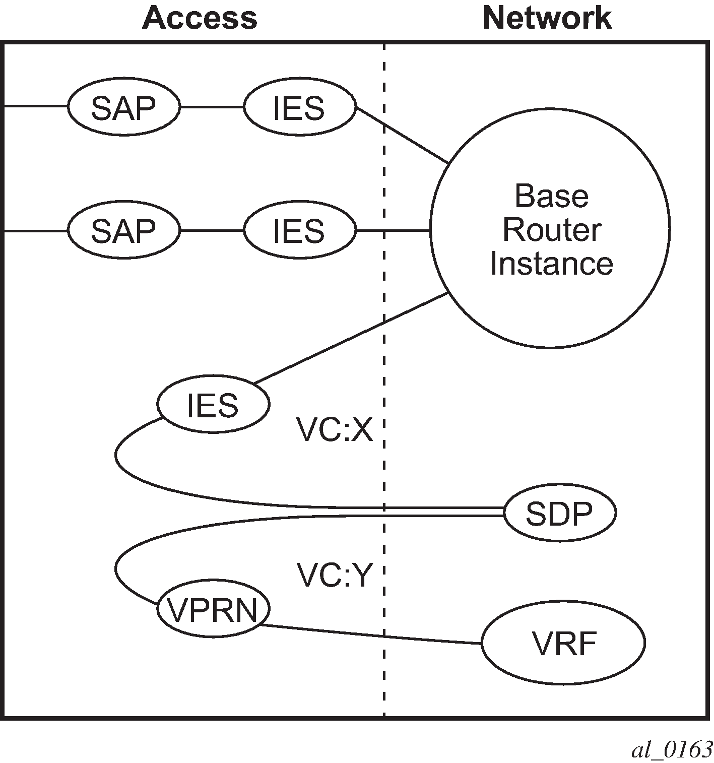
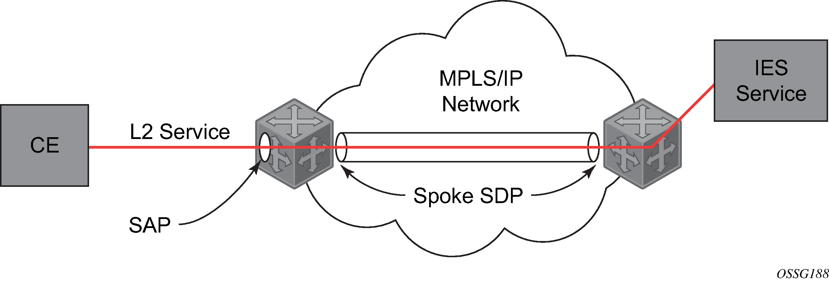
IES spoke-SDP termination depicts a spoke SDP terminating directly into a Layer 3 service interface (IES or VPRN) at one end, and a Layer 2 service (Epipe or VPLS) at the other. There is no special configuration required on the Layer 2 service.
Spoke SDPs created with vc-type ether (the default) are compatible with Epipe and VPLS services, as well as with other IES/VPRN interfaces.
If the MPLS network uses LDP signaling, then in order for a spoke SDP to function, the LDP binding MTUs at each end must match. For a Layer 2 service, the MTU of the local binding is 14 octets less than the configured service MTU (such as, binding MTU = service MTU - 14). For an IES or VPRN interface, the binding MTU is equal to either the configured ip-mtu of the interface, or the SDP’s path-mtu minus 14, whichever is lower. Use the following command to find the local and remote MTUs of all bindings.
show router ldp bindingsAll routing protocols that are supported by IES/VPRN are supported for spoke-SDP termination.
See "VCCV BFD support for VLL, spoke SDP termination on IES and VPRN, and VPLS services" in the 7705 SAR Gen 2 Layer 2 Services and EVPN Guide for information about using VCCV BFD in spoke-SDP termination.
show router ldp bindings servicesConfiguring an IES service with CLI
This section provides information to configure IES services using the CLI.
Basic configuration
The most basic IES service configuration has the following entities:
-
customer ID (see the 7705 SAR Gen 2 Services Overview Guide for more information)
an interface to create and maintain IP routing interfaces within IES service ID
a SAP on the interface specifying the access port and encapsulation values
The following example shows the configuration of an IES service.
MD-CLI
[ex:/configure service]
A:admin@node-2# info
    ies "1000" {
        admin-state enable
        description "to internet"
        customer "1"
        vpn-id 1000
        interface "to-web" {
            sap 1/1/5:0.* {
            }
            ipv4 {
                primary {
                    address 10.1.1.1
                    prefix-length 24
                }
            }
        }
    }
classic CLI
A:node-2>config>service# info
----------------------------------------------
        ies 1000 name "1000" customer 1 vpn 1000 create
            description "to internet"
            interface "to-web" create
                address 10.1.1.1/24
                sap 1/1/5:0.* create
                exit
            exit
            no shutdown
        exit
----------------------------------------------
Common configuration tasks
This section provides a brief overview of the tasks that must be performed to configure IES services and provides the CLI commands.
Perform the following tasks to configure IES services.
- Associate an IES service with a customer ID.
- Associate customer ID with the service.
- Assign an IP address.
- Optional: Create a subscriber interface.
- Create an interface.
-
Define SAP command options on the interface.
- Select nodes and ports.
- Optional: Select QoS policies other than the default (configured in the configure qos context).
- Optional: Select filter policies (configured in the configure filter context).
- Optional: Select accounting policy (configured in the configure log context)y.
- Enable service.
Configuring IES components
Use the configuration information that follows to configure IES components.
Configuring an IES service
The following example displays a basic IES service configuration.
IES service configuration for the 7705 SAR Gen 2 (MD-CLI)
[ex:/configure service]
A:admin@node-2# info
    ies "1001" {
        admin-state enable
        description "to-internet"
        customer "1"
        vpn-id 1001
    }
IES service configuration for the 7705 SAR Gen 2 (classic CLI)
A:node-2>config>service# info
----------------------------------------------
        ies 1001 name "1001" customer 1 vpn 1001 create
            description "to-internet"
            no shutdown
        exit
----------------------------------------------
Configuring IES subscriber interfaces
Subscriber interfaces operate only with basic (or enhanced) subscriber management. At the very least, a host, either statically configured or dynamically learned by DHCP must be present in order for the interface to be useful.
The following example displays a subscriber interface configuration for the 7705 SAR Gen 2.
MD-CLI
[ex:/configure service ies "11" subscriber-interface "test1"]
A:admin@node-2# info
    ipv4 {
        address 192.168.140.1 {
            prefix-length 24
        }
    }
    group-interface "abc-if" {
        sap 1/1/19:0 {
            ingress {
                qos {
                    sap-ingress {
                        policy-name "2"
                    }
                }
                filter {
                    ip "10"
                }
            }
            static-host {
                ipv4 192.168.145.100 mac 00:01:00:00:00:01 {
                }
            }
        }
classic CLI
A:node-2>config>service>ies>sub-if# info
----------------------------------------------
                address 192.168.140.1/24
                group-interface "abc-if" create
                    sap 1/1/19:0 create
                        ingress
                            qos 2
                            filter ip 10
                        exit
                        static-host ip 192.168.145.100 mac 00:01:00:00:00:01 create
                        exit
                    exit
                exit
----------------------------------------------
Configuring IES interfaces
The following examples show the configuration of IES interfaces.
IES configuration for the 7705 SAR Gen 2 (MD-CLI)
[ex:/configure service ies "2" interface "test2"]
A:admin@node-2# info
    sap 1/1/10:0.* {
        ingress {
            qos {
                sap-ingress {
                    policy-name "100"
                }
            }
        }
        egress {
            qos {
                scheduler-policy {
                    policy-name "SLA1"
                }
            }
        }
    }
    ipv4 {
        primary {
            address 10.1.1.1
            prefix-length 24
        }
        vrrp 1 {
            authentication-key "McTNkSePNJMVFysxyZa4y4D+iaD7lJ4= hash2"
        }
    }
IES configuration for the 7705 SAR Gen 2 (classic CLI)
A:node-2>config>service>ies>if$ info
----------------------------------------------
                address 10.1.1.1/24
                vrrp 1 owner
                    authentication-key "McTNkSePNJMVFysxyZa4y4D+iaD7lJ4=" hash2
                exit
                sap 1/1/10:0.* create
                    ingress
                        qos 100
                    exit
                    egress
                        scheduler-policy "SLA1"
                    exit
                exit
----------------------------------------------
Configuring a spoke SDP
The following example shows a spoke-SDP configuration for the 7705 SAR Gen 2.
MD-CLI
[ex:/configure service ies "4"]
A:admin@node-2# info
    admin-state enable
    description "to internet"
    customer "1"
    interface "spokeSDP-test" {
        spoke-sdp 2:100 {
            egress {
                filter {
                    ip "10"
                }
            }
        }
    }
classic CLI
A:node-2>config>service>ies# info
----------------------------------------------
            description "to internet"
            interface "spokeSDP-test" create
                spoke-sdp 2:100 create
                    egress
                        filter ip 10
                    exit
                exit
            exit
            no shutdown
----------------------------------------------
Configuring a SAP
A service access point (SAP) is a combination of a port and encapsulation command options that identifies the SAP on the interface and within the router. Each SAP must be unique within a router.
When configuring IES SAP command options on a 7705 SAR Gen 2, a default QoS policy is applied to each ingress and egress SAP. Additional QoS policies and scheduler policies must be configured in the configure qos context. Filter policies are configured in the configure filter context and must be explicitly applied to a SAP. There are no default filter policies.
IES SAP configuration for the 7705 SAR Gen 2 (MD-CLI)
[ex:/configure service ies "2"]
A:admin@node-2# info
    customer "1"
    interface "test2" {
        sap 5/1/3.1:0 {
            ingress {
                qos {
                    sap-ingress {
                        policy-name "101"
                    }
                }
            }
            egress {
                qos {
                    sap-egress {
                        policy-name "1010"
                    }
                    scheduler-policy {
                        policy-name "alpha"
                    }
                }
            }
        }
        ipv4 {
            primary {
                address 10.10.36.2
                prefix-length 24
            }
        }
    }
IES SAP configuration for the 7705 SAR Gen 2 (classic CLI)
A:node-2>config>service>ies>if# info
----------------------------------------------
                address 10.10.36.2/24
                sap 5/1/3.1:0 create
                    ingress
                        qos 101
                    exit
                    egress
                        scheduler-policy "alpha"
                        qos 1010
                    exit
                exit
----------------------------------------------
Configuring VRRP
VRRP can be configured in either an owner or non-owner mode. The owner is the VRRP router whose virtual router IP address is the same as the real interface IP address. This is the router that responds to packets addressed to one of the IP addresses for ICMP pings, TCP connections, and so on. All other virtual router instances participating in this message domain must have the same VRID configured and cannot be configured as owner.
See the 7705 SAR Gen 2 Router Configuration Guide for more information about VRRP.
The following example shows the VRRP on an IES interface configuration.
MD-CLI
[ex:/configure service ies "16"]
A:admin@node-2# info
    customer "1"
    interface "test16" {
        ipv4 {
            primary {
                address 10.10.36.2
                prefix-length 24
            }
            vrrp 2 {
                authentication-key "McTNkSePNJMVFysxyZa4y1fsBIiad0g= hash2"
                backup [10.10.36.2]
                owner true
            }
        }
    }
classic CLI
A:node-2>config>service>ies>if$ info
----------------------------------------------
                address 10.10.36.2/24
                vrrp 2 owner
                    backup 10.10.36.2
                    authentication-key "McTNkSePNJMVFysxyZa4y1fsBIiad0g=" hash2
                exit
----------------------------------------------
Configuring IPsec
The following example shows an IES service with IPsec configured for the 7705 SAR Gen 2.
MD-CLI
[ex:/configure service]
A:admin@node-2# info
    ies "100" {
        admin-state enable
        customer "1"
        interface "ipsec-public" {
            admin-state enable
            sap ipsec-1.public:1 {
            }
            ipv4 {
                primary {
                    address 10.10.10.1
                    prefix-length 24
                }
            }
        }
    }
classic CLI
A:node-2>config# info
----------------------------------------------
...
    service
        ies 100 customer 1 create
            interface "ipsec-public" create
                address 10.10.10.1/24
                sap ipsec-1.public:1 create
                exit
            exit
            no shutdown
        exit
    exit
...
----------------------------------------------
IGMP host tracking
The following example shows an IES service with IGMP host tracking configured.
MD-CLI
[ex:/configure service]
A:admin@node-2# info
...
    ies "25" {
        admin-state enable
        customer "1"
        interface "ip_if_4" {
            ip-mtu 9000
            tos-marking-state untrusted
            sap lag-64:64 {
            }
            hold-time {
                ipv4 {
                    down {
                        seconds 1200
                    }
                }
            }
            ipv4 {
                allow-directed-broadcasts true
                local-dhcp-server "server 1"
                urpf-check {
                }
                primary {
                    address 10.64.64.64
                    prefix-length 24
                }
                secondary 10.3.4.5 {
                    prefix-length 24
                }
                neighbor-discovery {
                    local-proxy-arp true
                    remote-proxy-arp true
                    proxy-arp-policy ["treetrace-1"]
                }
                dhcp {
                    admin-state enable
                    description "server 1"
                    server [192.168.17.1]
                }
            }
        }
        igmp-host-tracking {
            expiry-time 65535
        }
classic CLI
A:node-2>config>service# info
----------------------------------------------
...
        ies 25 name "25" customer 1 create
            shutdown
            igmp-host-tracking
                expiry-time 65535
                no shutdown
            exit
            interface "ip_if_4" create
                hold-time
                    down ip 1200
                exit
                address 10.64.64.64/24
                secondary 10.3.4.5/24
                allow-directed-broadcasts
                tos-marking-state trusted
                dhcp
                    shutdown
                    description "server 1"
                    server 192.168.17.1
                exit
                ip-mtu 9000
                local-dhcp-server "server 1"
                local-proxy-arp
                proxy-arp-policy treetrace-1
                remote-proxy-arp
                sap lag-64:64 create
                exit
                urpf-check
                exit
            exit
        exit
Service management tasks
This section describes the IES service management tasks.
Modifying IES service command options
Existing IES service command options in the CLI or NMS can be modified, added, removed, enabled or disabled. Changes you make are applied immediately to all services.
To display a list of customer IDs, use the show service customer command. Enter the command options (such as description, SAP information and SDP information), and then enter the new information.
Modified service configuration for the 7705 SAR Gen 2 (MD-CLI)
[ex:/configure service]
A:admin@node-2# info
    ies "1000" {
        admin-state enable
        description "This is a new description"
        customer "1"
        vpn-id 1000
        interface "to-web" {
            mac 00:dc:98:1d:00:00
            sap 22/1/50:0 {
            }
            ipv4 {
                allow-directed-broadcasts true
                primary {
                    address 10.1.1.1
                    prefix-length 24
                }
            }
        }
    }
Modified service configuration for the 7705 SAR Gen 2 (classic CLI)
A:node-2>config>service# info
----------------------------------------------
        ies 1000 name "1000" customer 1 vpn 1000 create
            description "This is a new description"
            interface "to-web" create
                address 10.1.1.1/24
                mac 00:dc:98:1d:00:00
                allow-directed-broadcasts
                sap 22/1/50:0 create
                exit
            exit
            no shutdown
        exit
----------------------------------------------
Deleting a spoke SDP
The following example shows how to delete a spoke SDP (10.100) from the interface configuration (spoke-SDP-test interface) for the 7705 SAR Gen 2.
Delete a spoke SDP (MD-CLI)
[ex:/configure service ies "14" interface "spokeSDP-test"]
A:admin@node-2# delete spoke-sdp 10:100
Delete a spoke SDP (classic CLI)
In classic CLI, the service interface must be shutdown to delete the spoke SDP. This cleans up the associated VC labels.
*A:node-2>config>service>ies# shutdown
*A:node-2>config>service>ies# interface "spokeSDP-test"
*A:node-2>config>service>ies>if# shutdown
*A:node-2>config>service>ies>if# spoke-sdp 10:100
*A:node-2>config>service>ies>if>spoke-sdp# shutdown
*A:node-2>config>service>ies>if>spoke-sdp# exit
*A:node-2>config>service>ies>if# no spoke-sdp 10:100
Deleting an IES service
The following example shows the deletion of an IES service.
Delete an IES service (MD-CLI)
[ex:/configure service]
A:admin@node-2# delete ies 13
Delete an IES service (classic CLI)
In classic CLI, an IES service cannot be deleted until SAPs and interfaces are shut down and deleted and the service is shutdown on the service level.
*A:node-2>config>service>ies# interface "test3"
*A:node-2>config>service>ies>if# sap 1/1/7:0.*
*A:node-2>config>service>ies>if>sap# shutdown
*A:node-2>config>service>ies>if>sap# exit
*A:node-2>config>service>ies>if# no sap 1/1/7:0.*
*A:node-2>config>service>ies>if# shutdown
*A:node-2>config>service>ies>if# exit
*A:node-2>config>service>ies# no interface "test3"
*A:node-2>config>service>ies# shutdown
*A:node-2>config>service>ies# exit
*A:node-2>config>service# no ies 13
Disabling an IES service
The following example shows the disabling of an IES service. You can disable an IES service without deleting the service command options.
Disabling of an IES service (MD-CLI)
[ex:/configure service ies "12"]
A:admin@node-2# admin-state disable

[ex:/configure service ies "12"]
A:admin@node-2# info
    admin-state disable
    customer "1"
    interface "test2" {
...
Disabling of an IES service (classic CLI)
A:node-2>config>service>ies# shutdown
A:node-2>config>service>ies# info
----------------------------------------------
            shutdown
            interface "test2" create
...
Re-enabling an IES service
The following example shows how to re-enable an IES service that was administratively disabled.
Re-enabling an IES service (MD-CLI)
[ex:/configure service ies "12"]
A:admin@node-2# admin-state enable

[ex:/configure service ies "12"]
A:admin@node-2# info
    admin-state enable
    customer "1"
    interface "test2" {
...
Re-enabling an IES service (classic CLI)
A:node-2>config>service>ies# no shutdown
A:node-2>config>service>ies# info
----------------------------------------------
            interface "test2" create
                address 10.1.1.1/24
...