PIM
This chapter provides information about PIM.
PIM-SM
PIM-SM leverages the unicast routing protocols that are used to create the unicast routing table, OSPF, IS-IS, BGP, and static routes. Because PIM uses this unicast routing information to perform the multicast forwarding function it is effectively IP protocol independent. Unlike DVMRP, PIM does not send multicast routing tables updates to its neighbors.
PIM-SM uses the unicast routing table to perform the Reverse Path Forwarding (RPF) check function instead of building up a completely independent multicast routing table.
PIM-SM only forwards data to network segments with active receivers that have explicitly requested the multicast group. PIM-SM in the ASM model initially uses a shared tree to distribute information about active sources. Depending on the configuration options, the traffic can remain on the shared tree or switch over to an optimized source distribution tree. As multicast traffic starts to flow down the shared tree, routers along the path determine if there is a better path to the source. If a more direct path exists, then the router closest to the receiver sends a join message toward the source and then reroutes the traffic along this path.
As stated above, PIM-SM relies on an underlying topology-gathering protocol to populate a routing table with routes. This routing table is called the Multicast Routing Information Base (MRIB). The routes in this table can be taken directly from the unicast routing table, or it can be different and provided by a separate routing protocol such as MBGP. Regardless of how it is created, the primary role of the MRIB in the PIM-SM protocol is to provide the next hop router along a multicast-capable path to each destination subnet. The MRIB is used to determine the next hop neighbor to whom any PIM join/prune message is sent. Data flows along the reverse path of the join messages. Thus, in contrast to the unicast RIB that specifies the next hop that a data packet would take to get to some subnet, the MRIB gives reverse-path information, and indicates the path that a multicast data packet would take from its origin subnet to the router that has the MRIB.
PIM-SM functions
PIM-SM functions have three phases.
Phase one
In this phase, a multicast receiver expresses its interest in receiving traffic destined for a multicast group. Typically it does this using IGMP, but other mechanisms may also serve this purpose. One of the local routers of the receiver is elected as the designated router (DR) for that subnet. When the expression of interest is received, the DR sends a PIM join message toward the RP for that multicast group. This join message is known as a (*,G) join because it joins group G for all sources to that group. The (*,G) join travels hop-by-hop toward the RP for the group, and in each router it passes through, the multicast tree state for group G is instantiated.
Eventually, the (*,G) join either reaches the RP or reaches a router that already has the (*,G) join state for that group. When many receivers join the group, their join messages converge on the RP and form a distribution tree for group G that is rooted at the RP. The distribution tree is called the RP tree or the shared tree (because it is shared by all sources sending to that group). Join messages are re-sent periodically as long as the receiver remains in the group. When all receivers on a leaf network leave the group, the DR sends a PIM (*,G) prune message toward the RP for that multicast group. However, if the prune message is not sent for any reason, the state eventually times out.
A multicast data sender starts sending data destined for a multicast group. The local router of the sender (the DR) takes these data packets, unicast-encapsulates them, and sends them directly to the RP. The RP receives these encapsulated data packets, removes the encapsulation, and forwards them to the shared tree. The packets then follow the (*,G) multicast tree state in the routers on the RP tree, and are replicated wherever the RP tree branches, and eventually reach all the receivers for that multicast group. The process of encapsulating data packets to the RP is called registering, and the encapsulation packets are known as PIM register packets.
At the end of phase one, multicast traffic is flowing encapsulated to the RP, and then natively over the RP tree to the multicast receivers.
Phase two
In this phase, register-encapsulation of data packets is performed. However, register-encapsulation of data packets is inefficient for the following reasons:
Encapsulation and de-encapsulation can be resource-intensive operations for a router to perform, depending on whether the router has appropriate hardware for the tasks.
Traveling to the RP and then back down the shared tree can cause the packets to travel a relatively long distance to reach receivers that are close to the sender. For some applications, increased latency is unwanted.
Although register-encapsulation can continue indefinitely, for the previous reasons, the RP normally switches to native forwarding. To do this, when the RP receives a register-encapsulated data packet from source S on group G, it normally initiates an (S,G) source-specific join toward S. This join message travels hop-by-hop toward S, instantiating an (S,G) multicast tree state in the routers along the path.
The (S,G) multicast tree state is used only to forward packets for group G if those packets come from source S. Eventually, the join message reaches the S subnet or a router that already has the (S,G) multicast tree state, and packets from S start to flow following the (S,G) tree state toward the RP. These data packets can also reach routers with a (*,G) state along the path toward the RP, and if this occurs, they take a shortcut to the RP tree at this point.
While the RP is in the process of joining the source-specific tree for S, the data packets continue being encapsulated to the RP. When packets from S also start to arrive natively at the RP, the RP receives two copies of each of these packets. At this point, the RP starts to discard the encapsulated copy of these packets and sends a register-stop message back to the DR of S to prevent the DR from unnecessarily encapsulating the packets. At the end of phase two, traffic is flowing natively from S along a source-specific tree to the RP and from there along the shared tree to the receivers. Where the two trees intersect, traffic can transfer from the shared RP tree to the shorter source tree.
Phase three
In this phase, the RP joins back toward the source using the shortest path tree (SPT). Although having the RP join back toward the source removes the encapsulation overhead, it does not completely optimize the forwarding paths. For many receivers, the route via the RP can involve a significant detour when compared with the shortest path from the source to the receiver.
To obtain lower latencies, a router on the LAN of the receiver, typically the DR, may optionally initiate a transfer from the shared tree to a source-specific SPT. To do this, it issues an (S,G) join toward S. This instantiates the (S,G) state in the routers along the path to S. Eventually, this join either reaches the S subnet or reaches a router that already has the (S,G) state. When this happens, data packets from S flow following the (S,G) state until they reach the receiver.
At this point, the receiver (or a router upstream of the receiver) is receiving two copies of the data—one from the SPT, and one from the RP tree. When the first traffic starts to arrive from the SPT, the DR or upstream router starts to drop the packets for G from S that arrive via the RP tree. In addition, it sends an (S,G) prune message toward the RP. The prune message travels hop-by-hop, instantiating an (S,G) state along the path toward the RP, indicating that traffic from S for G should not be forwarded in this direction. The prune message is propagated until it reaches the RP or a router that still needs the traffic from S for other receivers.
By now, the receiver is receiving traffic from S along the SPT between the receiver and S. In addition, the RP is receiving the traffic from S, but this traffic is no longer reaching the receiver along the RP tree. As far as the receiver is concerned, this is the final distribution tree.
Encapsulating data packets in the register tunnel
Conceptually, the register tunnel is an interface with a smaller MTU than the underlying IP interface toward the RP. IP fragmentation on packets forwarded on the register tunnel is performed based on this smaller MTU. The encapsulating DR can perform path-MTU discovery to the RP to determine the effective MTU of the tunnel. This smaller MTU takes both the outer IP header and the PIM register header overhead into consideration.
PIM bootstrap router mechanism
For correct operation, every PIM-SM router within a PIM domain must be able to map a particular global-scope multicast group address to the same RP. If this is not possible, black holes can appear (this is where some receivers in the domain cannot receive some groups). A domain in this context is a contiguous set of routers that all implement PIM and are configured to operate within a common boundary.
The Bootstrap Router (BSR) mechanism provides a way in which viable group-to-RP mappings can be created and distributed to all the PIM-SM routers in a domain. Each candidate BSR originates Bootstrap Messages (BSMs). Every BSM contains a BSR priority field. Routers within the domain flood the BSMs throughout the domain. A candidate BSR that hears about a higher-priority candidate BSR suppresses sending more BSMs for a period of time. The single remaining candidate BSR becomes the elected BSR, and its BSMs inform the other routers in the domain that it is the elected BSR.
The PIM bootstrap routing mechanism is adaptive, meaning that if an RP becomes unreachable, the event is detected and the mapping tables are modified so that the unreachable RP is no longer used, and the new tables are rapidly distributed throughout the domain.
PIM-SM routing policies
Multicast traffic can be restricted from specific source addresses by creating routing policies. Join messages can be filtered using import filters. PIM join policies can be used to reduce denial of service attacks and subsequent PIM state explosion in the router and to remove unwanted multicast streams at the edge of the network before it is carried across the core.
Use commands in the following context to configure route policies:
- MD-CLI
configure policy-options - classic
CLI
configure router policy-options
Join and register route policy match criteria for PIM-SM can specify the following:
router interface or interfaces specified by name or IP address
neighbor address (the source address in the IP header of the join and prune message)
multicast group address embedded in the join and prune message
multicast source address embedded in the join and prune message
Join policies can be used to filter PIM join messages so no (*,G) or (S,G) state is created on the router.
The following table lists the join filter policy match conditions.
| Match condition | Matches |
|---|---|
Interface |
RTR interface by name |
Neighbor |
The neighbors source address in the IP header |
Group Address |
Multicast Group address in the join/prune message |
Source Address |
Source address in the join/prune message |
PIM register message are sent by the first hop designated router that has a direct connection to the source. This serves a dual purpose:
notifies the RP that a source has active data for the group
delivers the multicast stream in register encapsulation to the RP and its potential receivers
if no one has joined the group at the RP, the RP ignores the registers
In an environment where the sources to particular multicast groups are always known, it is possible to apply register filters at the RP to prevent any unwanted sources from transmitting multicast stream. You can apply these filters at the edge so that register data does not travel unnecessarily over the network toward the RP.
The following table lists the register filter policy match conditions.
| Match condition | Matches |
|---|---|
Interface |
RTR interface by name |
Group Address |
Multicast Group address in the join/prune message |
Source Address |
Source address in the join/prune message |
RPF checks
Multicast implements a Reverse Path Forwarding (RPF) check. RPF checks the path that multicast packets take between their sources and the destinations to prevent loops. Multicast requires that an incoming interface be the outgoing interface used by unicast routing to reach the source of the multicast packet. RPF forwards a multicast packet only if it is received on an interface that is used by the router to route to the source.
If the forwarding paths are modified because of routing topology changes, any dynamic filters that may have been applied must be re-evaluated. If filters are removed, the associated alarms are also cleared.
Distributing PIM joins over multiple ECMP paths
The per bandwidth/round robin method is commonly used for multicast load-balancing, but the interface in an ECMP set can also be used for a specific channel to be predictable without knowledge of other channels that use the ECMP set.
Use the following command to distribute PIM joins over multiple ECMP paths based on a hash of S and G:
- MD-CLI
configure router pim mc-ecmp-hashing - classic
CLI
configure router pim mc-ecmp-hashing-enabled
When a link in the ECMP set is removed, multicast streams that use this link are redistributed over the remaining ECMP links using the same hash algorithm. When a link is added to the ECMP set, new joins may be allocated to the new link based on the hash algorithm. Existing multicast streams using the other ECMP links stay on those links until they are pruned, unless the rebalance command option is specified.
The default is not enabled, which means that the use of multiple ECMP paths (if enabled at the configure service vprn context) is controlled through the existing implementation and the mc-ecmp-balance command.
To achieve distribution of streams across the ECMP links, the hashing steps are as follows:
For a specific (S,G) get all possible next hops.
Sort these next hops based on next hop address.
XOR S and G addresses.
Hash the XORed address over the number of PIM next hops.
Use the hash value obtained in step 4, and set that element in the sorted list that was obtained in step 2 as the preferred next hop
If this element is not available or is not a PIM next hop (PIM neighbor), the next available next hop is chosen.
Use the following command to display the PIM status for the router instance.
show router 100 pim statusThe following example displays the PIM status indicating ECMP hashing is disabled.
PIM status indicating ECMP hashing is disabled
===============================================================================
PIM Status ipv4
===============================================================================
Admin State                       : Up
Oper State                        : Up

IPv4 Admin State                  : Up
IPv4 Oper State                   : Up

BSR State                         : Accept Any

Elected BSR
    Address                       : None
    Expiry Time                   : N/A
    Priority                      : N/A
    Hash Mask Length              : 30
    Up Time                       : N/A
    RPF Intf towards E-BSR        : N/A

Candidate BSR
    Admin State                   : Down
    Oper State                    : Down
    Address                       : None
    Priority                      : 0
    Hash Mask Length              : 30

Candidate RP
    Admin State                   : Down
    Oper State                    : Down
    Address                       : 0.0.0.0
    Priority                      : 192
    Holdtime                      : 150

SSM-Default-Range                 : Enabled
SSM-Group-Range
    None

MC-ECMP-Hashing                   : Disabled

Policy                            : None

RPF Table                         : rtable-u

Non-DR-Attract-Traffic            : Disabled
===============================================================================
Use commands in the following context to configure PIM.
configure service vprn pim - group-prefix shortest-path switchover thresholds
- interfaces
- import policies
- MC-ECMP traffic balancing or hash-based multicast balancing over ECMP links
- RP
- SSM group ranges
PIM configuration for a VPRN service (MD-CLI)
[ex:/configure service vprn "5" pim]
A:admin@node-2# info
    admin-state enable
    apply-to all
    mc-ecmp-balance false
    mc-ecmp-hashing {
        rebalance true
    }
    rp {
        ipv4 {
            bsr-candidate {
                admin-state disable
            }
            static {
                address 10.3.3.3 {
                    group-prefix 224.0.0.0/4 { }
                }
            }
        }
            rp-candidate {
                admin-state disable
            }
        }
    }
PIM configuration for a VPRN service (classic CLI)
---------------------------------------------
A:node-2>config>service>vprn>pim# info
----------------------------------------------
                apply-to all
                rp
                    static
                        address 10.3.3.3
                            group-prefix 224.0.0.0/4
                        exit
                    exit
                    bsr-candidate
                        shutdown
                    exit
                    rp-candidate
                        shutdown
                    exit
                exit
                no mc-ecmp-balance
                mc-ecmp-hashing-enabled
                no shutdown
----------------------------------------------
Use the following command to show distribution of PIM joins over multiple ECMP paths for the specified router instance.
show router 100 pim groupDistribution of PIM joins over multiple ECMP paths
===============================================================================
PIM Groups ipv4
===============================================================================
Group Address                           Type     Spt Bit Inc Intf       No.Oifs
   Source Address                          RP
-------------------------------------------------------------------------------
239.1.1.1                               (S,G)    spt     to_C0          1
   172.0.100.33                            10.20.1.6
239.1.1.2                               (S,G)    spt     to_C3          1
   172.0.100.33                            10.20.1.6
239.1.1.3                               (S,G)    spt     to_C2          1
   172.0.100.33                            10.20.1.6
239.1.1.4                               (S,G)    spt     to_C1          1
   172.0.100.33                            10.20.1.6
239.1.1.5                               (S,G)    spt     to_C0          1
   172.0.100.33                            10.20.1.6
239.1.1.6                               (S,G)    spt     to_C3          1
   172.0.100.33                            10.20.1.6

239.2.1.1                               (S,G)    spt     to_C0          1
   172.0.100.33                            10.20.1.6
239.2.1.2                               (S,G)    spt     to_C3          1
   172.0.100.33                            10.20.1.6
239.2.1.3                               (S,G)    spt     to_C2          1
   172.0.100.33                            10.20.1.6
239.2.1.4                               (S,G)    spt     to_C1          1
   172.0.100.33                            10.20.1.6
239.2.1.5                               (S,G)    spt     to_C0          1
   172.0.100.33                            10.20.1.6
239.2.1.6                               (S,G)    spt     to_C3          1
   172.0.100.33                            10.20.1.6

239.3.1.1                               (S,G)    spt     to_C0          1
   172.0.100.33                            10.20.1.6
239.3.1.2                               (S,G)    spt     to_C3          1
   172.0.100.33                            10.20.1.6
239.3.1.3                               (S,G)    spt     to_C2          1
   172.0.100.33                            10.20.1.6
239.3.1.4                               (S,G)    spt     to_C1          1
   172.0.100.33                            10.20.1.6
239.3.1.5                               (S,G)    spt     to_C0          1
   172.0.100.33                            10.20.1.6
239.3.1.6                               (S,G)    spt     to_C3          1
   172.0.100.33                            10.20.1.6

239.4.1.1                               (S,G)    spt     to_C0          1
   172.0.100.33                            10.20.1.6
239.4.1.2                               (S,G)    spt     to_C3          1
   172.0.100.33                            10.20.1.6
239.4.1.3                               (S,G)    spt     to_C2          1
   172.0.100.33                            10.20.1.6
239.4.1.4                               (S,G)    spt     to_C1          1
   172.0.100.33                            10.20.1.6
239.4.1.5                               (S,G)    spt     to_C0          1
   172.0.100.33                            10.20.1.6
239.4.1.6                               (S,G)    spt     to_C3          1
   172.0.100.33                            10.20.1.6
-------------------------------------------------------------------------------
Groups : 24
===============================================================================
PIM interface on IES subscriber group interfaces
PIM on a subscriber group interface allows for SAP-level replication over an ESM Group interface by establishing PIM adjacency to a downstream router. The following figure depicts the model.
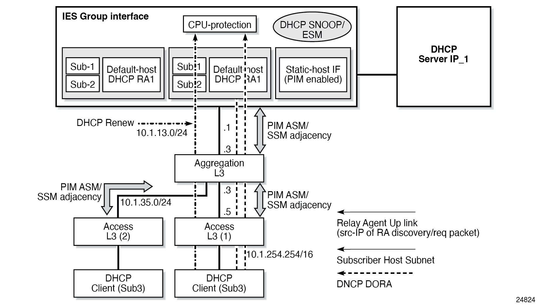
On an IES subscriber-interface, an Ethernet SAP is configured (LAG or physical port). On the SAP, a static-host is configured for connectivity to downstream Layer 3 aggregation devices (including PIM adjacency) while multiple default-hosts can be configured for subscriber traffic. Single SAP with a single static-host per group interface is supported to establish PIM adjacency on a subscriber group interface. Both IPv4 PIM ASM and SSM are supported.
Feature restrictions:
-
Only IPv4 PIM is supported with a single static host used to form a PIM interface under a group interface. Using multiple hosts or non-static hosts is not supported. Configuring IPv6 in the following context is not blocked, but takes no effect.
configure router pim interface -
The following command does not apply to PIM interfaces on IES subscriber group interfaces.
configure router pim apply-to -
PIM on group interfaces is not supported in VPRN context.
-
Extranet is not supported.
-
Locally attached receivers are not supported (no IGMP or MLD and PIM mix in OIF list).
-
Default anti-spoofing must be configured (IP+MAC).
-
A subscriber profile with a PIM policy enabled (configure subscriber-mgmt sub-profile) cannot combine with the following policies:
- host tracking policy
This option applies a host tracking policy.
- IGMP policy
This option applies an IGMP policy.
- MLD policy
This option applies an MLD policy.
- NAT policy
This option applies a NAT policy.
- Subscriber MCAC policy
This option applies a subscriber MCAC policy that can be used when configured in PIM interface context.
- host tracking policy
VRRP aware PIM
The Virtual Router Redundancy Protocol (VRRP) eliminates the single point of failure inherent in the static default-routed environment. VRRP describes a method of implementing a redundant IP interface that provides dynamic failover if the VRRP master router (MR) becomes unavailable.
VRRP provides information about the state of a router. However, PIM operates independently of VRRP group states. The PIM DR and the VRRP MR may not be the same router and IP multicast traffic may not necessarily follow the same path as elected by VRRP.
To leverage the redundancy capabilities of VRRP that are lacking in PIM, the VRRP Aware PIM mechanism allows PIM to monitor and react to changes in the VRRP MR. This ensures that the multicast traffic follows the unicast traffic through the same gateway as the VRRP MR, providing consistent IP multicast forwarding in a redundant network.
Configuring VRRP aware PIM
The VRRP Aware PIM feature enables PIM to track the state of a VRRP instance and to identify whether the associated VRRP interface is the master. PIM uses an operational group option (oper-group group-name) to monitor the state of VRRP. One operational group can be created for IPv4, and another for IPv6. When VRRP is the MR, the operational group is up; for all other VRRP states, the operational group is down. A VRRP instance can only be associated with one operational group, and an operational group can have one or more associated VRRP instances. This feature is supported on base router, IES, and VPRN interfaces.
If the monitored interface is the VRRP MR, PIM becomes the DR by setting its priority to the configured oper-group active-priority value. For the router to become the DR, the correct priorities must be configured so the active priority of the oper-group is the highest priority on the IP interface.
If a PIM router is the DR and then receives an indication from VRRP that the interface is no longer the VRRP MR, PIM relinquishes the DR role by setting its priority back to the default or configured priority value.
If the configured VRRP instance or oper-group is not configured, PIM operates as normal with the default or configured priority value. A change in the operational group status is independent of the address family; IPv4 and IPv6 priorities are configured independently of each other. Two operational groups are supported per PIM interface, one for IPv4 and one for IPv6.
Guidelines for configuring VRRP Aware PIM
When configuring VRRP Aware PIM, consider the following recommendations:
-
Configure VRRP to use BFD to speed up failure detection in addition to the functionality provided by VRRP Aware PIM.
-
To optimize failover, enable the following command on the primary and secondary routers to make them a hot-standby redundant pair.
configure router pim non-dr-attract-trafficNote: This configuration ignores the DR state and attracts traffic to populate the router’s PIM database. Do not use this configuration if multicast traffic must only follow the VRRP MR. -
Configure the group up time on the primary router and the group down time on the secondary router to the time needed to repopulate the PIM database; for example, 10 seconds. This allows the primary router to populate its PIM database again before becoming the DR and recover from the secondary back to the primary router if a failure occurs from the primary to secondary router. Use the following commands to configure the up and down times.
configure service oper-group hold-time group up
configure service oper-group hold-time group down
Configure the up time on the secondary router to 0, so that it assumes the DR role immediately if the primary router fails. The up hold time is set to 4 seconds by default, which delays the DR change unnecessarily.
-
Sticky DR enables the secondary router to continue to act as the DR after the primary router comes back up. Sticky DR is incompatible with the VRRP Aware PIM mechanism that tracks the VRRP MR. You should disable it if it is configured with the following command.
configure router pim interface sticky-dr
The following example shows a basic configuration for VRRP Aware PIM.
MD-CLI
[ex:/configure service]
A:admin@node-2# info
    interface "to-lan" {
        ipv4 {
            vrrp 1 {
                oper-group "VAwP1"
            }
        }
    }
    interface "to-lan2" {
        ipv4 {
            vrrp 1 {
                oper-group "VAwP2"
            }
        }
    }
    oper-group "VAwP1" {
    }
    oper-group "VAwP2" (
    }
    vprn "1" {
        customer "1"
        pim {
            interface "to-lan" {
                ipv4 {
                    monitor-oper-group {
                        name "VAwP1"
                        operation add
                        priority-delta 90
                    }
                }
                ipv6 {
                    monitor-oper-group {
                        name "VAwP1"
                        operation add
                        priority-delta 90
                    }
                }
            }
            interface "to-lan2" {
                ipv4 {
                    monitor-oper-group {
                        name "VAwP2"
                        operation add
                        priority-delta 90
                    }
                }
                ipv6 {
                    monitor-oper-group {
                        name "VAwP2"
                        operation add
                        priority-delta 90
                    }
                }
            }
        }
    }
classic CLI
A:node-2>config>service# info
----------------------------------------------
    oper-group ‟VAwP1” create
    oper-group ‟VAwP2” create
    exit
    vprn 1 customer 1 create
        shutdown
        interface to-lan
            vrrp 1 create
                oper-group ‟VAwP1”
            exit
         exit
        interface to-lan2
            vrrp 1 create
                oper-group ‟VAwP2”
            exit
         exit
         pim
            interface to-lan
                monitor-oper-group ‟VAwP1” family ipv4 add 90
                monitor-oper-group ‟VAwP1” family ipv6 add 90
            exit
            interface to-lan2
                monitor-oper-group ‟VAwP2” family ipv4 add 90
                monitor-oper-group ‟VAwP2” family ipv6 set 90
            exit
      exit
exit
IPv6 PIM models
IPv6 multicast enables multicast applications over native IPv6 networks. There are two service models: Any Source Multicast (ASM) and Source Specific Multicast (SSM) which includes PIM-SSM and MLD (see MLD overview). SSM does not require source discovery and only supports single source for a specific multicast stream. As a result, SSM is easier to operate in a large scale deployment that uses the one-to-many service model.
PIM-SSM
The Source Specific Multicast (SSM) service model defines a channel identified by an (S,G) pair, where S is a source address and G is an SSM destination address. In contrast to the ASM model, SSM only provides network-layer support for one-to-many delivery.
The SSM service model attempts to alleviate the following deployment problems that ASM has presented:
address allocation
SSM defines channels on a per-source basis. For example, the channel (S1,G) is distinct from the channel (S2,G), where S1 and S2 are source addresses, and G is an SSM destination address. This averts the problem of global allocation of SSM destination addresses and makes each source independently responsible for resolving address collisions for the various channels it creates.
access control
SSM provides an efficient solution to the access control problem. When a receiver subscribes to an (S,G) channel, it receives data sent only by the source S. In contrast, any host can transmit to an ASM host group. At the same time, when a sender picks an (S,G) channel to transmit on, it is automatically ensured that no other sender transmits on the same channel (except in the case of malicious acts such as address spoofing). This makes it harder to spam an SSM channel than an ASM multicast group.
handling of well-known sources
SSM requires only source-based forwarding trees, eliminating the need for a shared tree infrastructure. In terms of the IGMP, PIM-SM, MSDP, MBGP protocol suite, this implies that neither the RP-based shared tree infrastructure of PIM-SM nor the MSDP protocol is required. Thus, the complexity of the multicast routing infrastructure for SSM is low, making it viable for immediate deployment. MBGP is still required for distribution of multicast reachability information.
anticipating that point-to-multipoint applications such as Internet TV will be significant in the future, the SSM model is better suited for such applications.
System PIM SSM scaling
PIM SSM scaling can be increased to 256k (S,G)s using the pim-ssm-scaling command. This command enables (S,G) scaling for PIM SSM in the global routing table only. The current scaling limitation of (S,G)s per complex (FP) still exist. However, the 256K (S,G)s can be configured over multiple complex to achieve this higher scaling.
When PIM SSM scaling is enabled, the following multicast features are disabled:
DM
MoFRR
JP policy
SSM groups
(S,G) programming is a maximum of 32000 per complex
InBand features (BIER and MLDP)
Extranet
ASM
This feature is only supported on CPM5s.
When the pim-ssm-scaling command is enabled and there is a mix of FP3, FP4, and FP5 cards in the system, Nokia recommends that you configure the following command with the dynamic option to ensure the system dynamically chooses the lowest denominator throughput card as multicast-plane throughput.
- MD-CLI
configure multicast-management chassis-level per-mcast-plane-capacity total-capacity dynamic - classic
CLI
configure mcast-management chassis-level per-mcast-plane-capacity total-capacity dynamic
To achieve fast failover when PIM SSM scaling is enabled, the default MCID is used which results in the multicast traffic being sent to all line cards and silently discarded where there is no receiver for that traffic. Consequently, the maximum achievable plane capacity for this traffic is constrained to that of the lowest performance FP. When the maximum link capacity from the fabric to the lowest-performance FP is reached, the link to that FP is overloaded causing the fabric to back-pressure the ingress and resulting in packet loss for all FPs. By using the default MCID, this capacity constraint is independent of whether the lowest-performance FP has a receiver on it or not.
If the multicast management chassis per-plane total capacity is configured to an explicit value which is larger than that supported by the lowest-performance FP, IMPM believes there is more plane capacity available than there really is and the result is (S,G) packet loss instead of blackholing.
By setting the multicast management chassis per-plane total capacity to dynamic, the system automatically sets the switch fabric multicast plane capacity to the minimum value supported by the fabric and all line cards in the system. IMPM then has the correct view of the available plane capacity and correctly blackholes (S,G)s when insufficient plane capacity is available. The total maximum multicast capacity is still constrained by the lowest-performance FP.
PIM ASM
configure router pim ipv6Embedded RP
The detailed protocol specification is defined in RFC 3956, Embedding the Rendezvous Point (RP) Address in an IPv6 Multicast Address. This RFC describes a multicast address allocation policy in which the address of the RP is encoded in the IPv6 multicast group address, and specifies a PIM-SM group-to-RP mapping to use the encoding, leveraging, and extending unicast-prefix-based addressing. This mechanism not only provides a simple solution for IPv6 inter-domain ASM but can be used as a simple solution for IPv6 intra-domain ASM with scoped multicast addresses as well. It can also be used as an automatic RP discovery mechanism in those deployment scenarios that would have previously used the Bootstrap Router protocol (BSR).
Configurable source IP address for PIM register messages
When PIM messages are transmitted over IGP shortcuts, their source IP addresses are selected by choosing the smallest IP address from available interfaces on the node. This can be undesirable because of security measures within the network, such as ACLs, that cause packets to drop. To prevent the messages from being dropped, SR OS supports configuring the source IP address of the register messages to any IP address, regardless of whether it resides on the node.
Use the following commands to configure the source IP address for register messages:
- MD-CLI
configure router pim ipv4 source-address register-message configure router pim ipv6 source-address register-message configure service vprn pim ipv4 source-address register-message configure service vprn pim ipv6 source-address register-message - classic
CLI
configure router pim source-address register-message
configure service vprn pim source-address register-message
Configuring PIM with CLI
This section provides information to configure PIM using the CLI.
PIM configuration overview
The PIM protocol is not operational until at least one interface is specified for it, at which time the interface is enabled for PIM and is called a PIM interface. When enabled, a PIM interface can be configured with PIM parameters in addition to the standard parameters for the interface when it is created. When PIM is operational, data is forwarded to network segments with active host receivers that have explicitly requested the multicast group.
Basic PIM configuration
Perform the following basic PIM configuration tasks:
-
Enable PIM (required)
-
Add interfaces so the protocol establishes adjacencies with the neighboring routers (required)
-
Configure a way to calculate group-to-RP mapping (required) by either:
-
static group-to-RP mapping
-
enabling Candidate RP/Bootstrap mechanism on some routers
-
-
Enable unicast routing protocols to learn routes toward the RP/source for reverse path forwarding (required)
-
Add SSM ranges (optional)
-
Enable Candidate BSR (optional)
-
Enable Candidate RP (optional)
-
Change hello interval (optional)
-
Configure route policies (bootstrap-export, bootstrap-import, import join and register)
PIM configuration
Configuring and enabling PIM
When configuring PIM, make sure to enable PIM on all interfaces for the routing instance, otherwise multicast routing errors can occur.
Use the commands in the following context to configure PIM.
configure router pimThe following example displays a basic configuration with PIM enabled.
MD-CLI
[ex:/configure router "Base" pim]
A:admin@node-2# info
    admin-state enable
    apply-to none
    rp {
        ipv4 {
            bsr-candidate {
                admin-state disable
                address 10.10.10.2
                priority 0
                hash-mask-len 30
            }
            rp-candidate {
                admin-state disable
                holdtime 150
                priority 192
                address 10.10.10.1
            }
            static {
                address 10.10.10.10 {
                }
                address 198.51.100.254 {
                    group-prefix 239.24.24.24/32 {
                }
            }
        }
    }
classic CLI
A:node-2>config>router# info
#------------------------------------------
echo "PIM Configuration"
#------------------------------------------
        pim
            apply-to none
            rp
                static
                    address 198.51.100.254
                        group-prefix 239.24.24.24/32
                    exit
                    address 10.10.10.10
                    exit
                exit
                bsr-candidate
                    shutdown
                    address 10.10.10.2
                    priority 0
                    hash-mask-len 30
                exit
                rp-candidate
                     shutdown
                     address 10.10.10.1
                     holdtime 150
                     priority 192
                exit
            exit
            no shutdown
        exit
------------------------------------------
Configuring PIM interfaces
You can reference router interfaces in the PIM configuration. You must create the interfaces first in the router context. Use the commands in the following context to configure and enable PIM router interfaces.
configure router pim interfaceThe following example shows a PIM configuration with basic interfaces configured.
MD-CLI
[ex:/configure router "base" pim]
A:admin@node-2# info
    admin-state enable
    apply-to all
    interface "lax-sjc" {
        admin-state enable
    }
    interface "lax-vls" {
        admin-state enable
    }
    interface "pl-ix" {
        admin-state enable
    }
    interface "system" {
        admin-state enable
    }
    rp {
        ipv4 {
            bsr-candidate {
                admin-state enable
                address 10.10.10.10
            }
            rp-candidate {
                admin-state enable
                address 10.10.10.1
            }
            static {
                address 10.10.10.1 {
                }
                address 198.51.100.254 {
                    group-prefix 239.24.24.24/32 { }
                }
            }
        }
    }
classic CLI
A:node-2>config>router>pim# info
----------------------------------------------
            interface "system"
                no shutdown
            exit
            interface "lax-sjc"
                no shutdown
            exit
            interface "lax-vls"
                no shutdown
            exit
            interface "pl-ix"
                no shutdown
            exit
            apply-to all
            rp
                static
                    address 10.10.10.1
                    exit
                    address 198.51.100.254
                        group-prefix 239.24.24.24/32
                    exit
                exit
                bsr-candidate
                    address 10.10.10.10
                    no shutdown
                exit
                rp-candidate
                    address 10.10.10.1
                    no shutdown
                exit
            exit
            no shutdown
----------------------------------------------
Configuring PIM join and register policies
Join policies are used in Protocol Independent Multicast (PIM) configurations to prevent the transportation of multicast traffic across a network and the dropping of packets at a scope at the edge of the network. PIM Join filters reduce the potential for denial of service (DoS) attacks and PIM state explosion—large numbers of Joins forwarded to each router on the RPT, resulting in memory consumption. See the Importing PIM Join/Register Policies section of the Multicast Routing Guide for more information.
(*,G) or (S,G) is the information used to forward unicast or multicast packets. The following options can be configured:
group-address
This matches the group address policy in join/prune messages group-address ‟group-address-policy”.
source-address
This is the source-address (192.168.0.1) that matches the source address in join/prune messages.
interface
This matches any join message received on the specified interface, for example, interface port 1/1/1
neighbor
This matches any join message received from the specified neighbor; for example, neighbor 1.1.1.1
Use commands in the following context to configure policy options:
- MD-CLI
configure policy-options - classic
CLI
configure router policy-options
The following configuration example does not allow join messages for the specified group address prefix list and source 192.168.0.1 but allows other join messages.
MD-CLI
[ex:/configure policy-options]
A:admin@cses-V208# info
    prefix-list "prefix-list-1" {
        prefix 192.0.2.0/24 type exact {
        }
    }
    policy-statement "Foo" {
        entry 10 {
            from {
                group-address "prefix-list-1"
                source-address {
                    ip-address 192.168.0.1
                }
            }
        }
    }
classic CLI
A:node-2>config>router>policy-options# info
----------------------------------------------
            prefix-list "prefix-list-1"
                prefix 192.0.2.0/24 exact
            exit
            policy-statement "Foo"
                entry 10
                    from
                        group-address "prefix-list-1"
                        source-address 192.168.0.1
                    exit
                exit
            exit
----------------------------------------------
Importing PIM join and register policies
An import mechanism is provided to control the (*,G) and (S,G) states that are created on the router.
Use the following commands to configure PIM join or register import policies.
configure router pim import join-policy
configure router pim import register-policy
The following example shows a PIM configuration with an imported policy applied. The policy would not allow join messages for group 229.50.50.208/32 and source 192.168.0.0/16 but would allow join messages for 192.168.0.0/16, 229.50.50.208 (see the ‟Configuring Route Policy Components” section of the 7705 SAR Gen 2 Unicast Routing Protocols Guide).
MD-CLI
[ex:/configure router "base" pim]
A:admin@node-2# info
    ...
    apply-to-all true
    import join-policy "foo"
    interface "lax-sjc" {
        admin-state enable
    }
    interface "lax-vls" {
        admin-state enable
    }
    interface "pl-ix" {
        admin-state enable
    }
    interface "system" {
        admin-state enable
    }
    rp {
        ipv4 {
            bsr-candidate {
                admin-state enable
                address 10.10.10.10
            }
            rp-candidate {
                admin-state enable
                address 10.10.10.1
            }
            static {
                address 10.10.10.1 {
                }
                address 198.51.100.254 {
                    group-prefix 239.24.24.24/32 { }
                }
            }
        }
    }
    ...
classic CLI
A:node-2>config>router>pim# info
----------------------------------------------
            ...
            import join-policy "foo"
            interface "system"
            exit
            interface "lax-sjc"
            exit
            interface "lax-vls"
            exit
            interface "pl-ix"
            exit
            apply-to all
            rp
                static
                    address 10.10.10.1
                    exit
                    address 198.51.100.254
                        group-prefix 239.24.24.24/32
                    exit
                exit
                bsr-candidate
                    address 10.10.10.10
                    no shutdown
                exit
                rp-candidate
                    address 10.10.10.1
                    no shutdown
                exit
            exit
            ...
----------------------------------------------
Configuring bootstrap message import and export policies
Bootstrap import and export policies are used to control the flow of bootstrap messages to and from the RP.
The following configuration example specifies that no BSR messages are received or sent out of interface port 1/1/1.
Configuration of import and export policy statements (MD-CLI)
[ex:/configure policy-options]
A:admin@node-2# info
    ...
    prefix-list "pim-policy-1" {
        prefix 10.0.0.0/16 longer
        prefix 10.10.186.0/24 longer
    }
    prefix-list "pim-policy-2"  {
        prefix 10.1.0.0/16 longer
    }
    policy-statement "pim-export-policy" {
        entry 10 {
            to {
                prefix-list "pim-policy-1" "pim-policy-2"
            }
            action {
                action-type reject
            }
        }
    }
    policy-statement "pim-import-policy" {
        entry 10 {
            from {
                interface ["port1"]
            }
            action {
                action-type reject
            }
        }
    }
    ...
Configuration of import and export policy statements (classic CLI)
A:node-2>config>router>policy-options# info
----------------------------------------------
        ...
        prefix-list "pim-policy-1"
            prefix 10.0.0.0/16 longer
            prefix 10.10.186.0/24 longer
        exit
        prefix-list "pim-policy-2"  {
            prefix 10.1.0.0/16 longer
        exit
        policy-statement "pim-import-policy"
            entry 10
                from
                    interface "port1"
                exit
                action drop
                exit
            exit
        exit
        policy-statement "pim-export-policy"
            entry 10
                to
                    prefix-list "pim-policy-1" "pim-policy-2"
                exit
                action accept
            exit
        exit
        ...
PIM configuration with import and export policies (MD-CLI)
[ex:/configure router "Base" pim]
A:node-2# info
    admin-state enable
    apply-to all
    interface "lax-sjc" {
    }
    interface "lax-vls" {
    }
    interface "pl-ix" {
    }
    interface "system" {
    }
    rp {
        bootstrap {
            import ["pim-import"]
        }
        bootstrap {
            export ["pim-export"]
        }
        ipv4 {
            bsr-candidate {
                admin-state disable
                priority 0
                address 10.10.10.10
                hash-mask-len 30
            }
            rp-candidate {
                admin-state enable
                address 10.10.10.1
            }
            static {
                address 10.10.10.1 {
                }
                address 198.51.100.254 {
                    group-prefix 239.24.24.24/32 { }
                }
            }
        }
    }
PIM configuration with import and export policies (classic CLI)
A:node-2>config>router>pim# info
----------------------------------------------
            interface "system"
            exit
            interface "lax-sjc"
            exit
            interface "lax-vls"
            exit
            interface "pl-ix"
            exit
            apply-to all
            rp
                bootstrap-import "pim-import"
                bootstrap-export "pim-export"
                static
                    address 10.10.10.1
                    exit
                    address 198.51.100.254
                        group-prefix 239.24.24.24/32
                    exit
                exit
                bsr-candidate
                    shutdown
                    address 10.10.10.10
                exit
                rp-candidate
                    address 10.10.10.1
                    no shutdown
                exit
            exit
            no shutdown
----------------------------------------------
Disabling PIM
Use the following commands to disable PIM:
- MD-CLI
configure router pim admin-state disable - classic
CLI
configure router pim shutdown