OAM fault and performance tools and protocols
This chapter provides information about the OAM fault and performance tools and protocols.
OAM overview
Delivery of services requires that a number of operations occur properly and at different levels in the service delivery model. For example, operations such as the association of packets to a service, VC labels to a service, and each service to a service tunnel must be performed properly in the forwarding plane for the service to function properly. To verify that a service is operational, a set of in-band, packet-based Operation, Administration, and Maintenance (OAM) tools is supported, with the ability to test each of the individual packet operations.
For in-band testing, the OAM packets closely resemble customer packets to effectively test the customer's forwarding path, but they are distinguishable from customer packets so they are kept within the service provider's network and not forwarded to the customer.
The suite of OAM diagnostics supplement the basic IP ping and traceroute operations with diagnostics specialized for the different levels in the service delivery model. There are diagnostics for MPLS LSPs, SR policies, SDPs, services, and VPLS MACs within a service.
LSP diagnostics for LDP, RSVP, and BGP labeled routes: LSP ping and LSP trace
The router LSP diagnostics include implementations of LSP ping and LSP trace based on RFC 8029, Detecting Multiprotocol Label Switched (MPLS) Data Plane Failures. LSP ping provides a mechanism to detect data plane failures in MPLS LSPs. LSP ping and LSP trace are modeled after the ICMP echo request or reply used by ping and trace to detect and localize faults in IP networks.
For a specific LDP FEC, RSVP P2P LSP, or BGP IPv4 or IPv6 labeled route, LSP ping verifies whether the packet reaches the egress label edge router (LER), while for LSP trace, the packet is sent to the control plane of each transit Label Switching Router (LSR) that performs various checks to see if it is intended to be a transit LSR for the path.
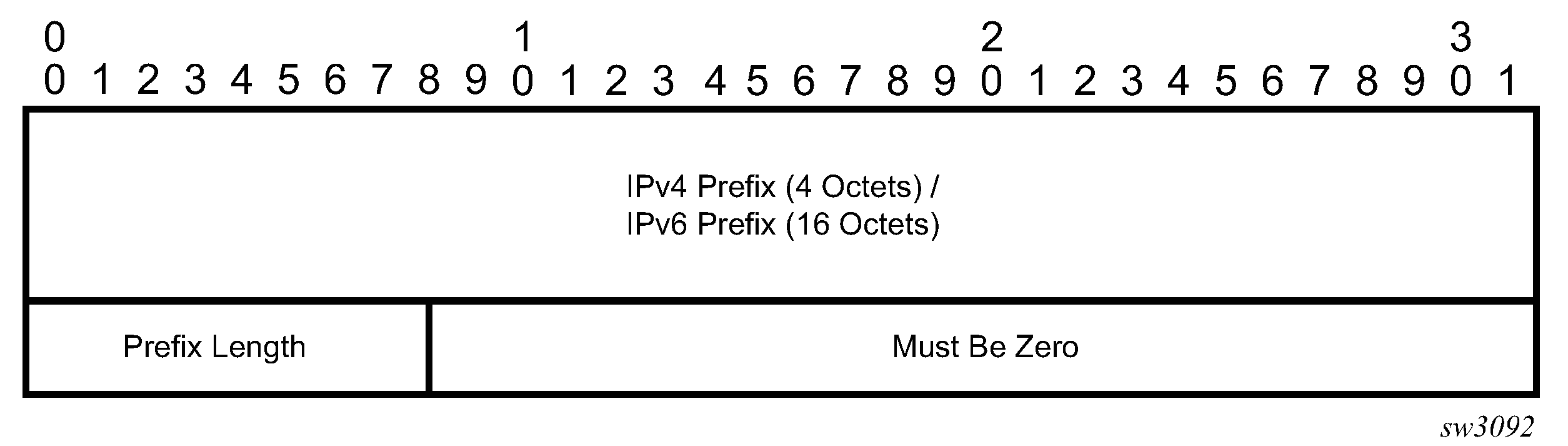
The downstream mapping TLV is used in LSP ping and LSP trace to provide a mechanism for the sender and responder nodes to exchange and validate interface and label stack information for each downstream hop in the path of an LDP FEC or an RSVP LSP.
Two downstream mapping TLVs are supported. The original Downstream Mapping (DSMAP) TLV defined in RFC 4379, Detecting Multiprotocol Label Switched (MPLS) Data Plane Failures, (obsoleted by RFC 8029) and the new Downstream Detailed Mapping (DDMAP) TLV defined in RFC 6424, Mechanism for Performing Label Switched Path Ping (LSP Ping) over MPLS Tunnels, and RFC 8029.
When the responder node has multiple equal cost next-hops for an LDP FEC prefix, the downstream mapping TLV can also be used to exercise a specific path of the ECMP set using the path-destination option. The behavior in this case is described in the ECMP sub-section that follows.
LSP ping/trace for an LSP using a BGP IPv4 or IPv6 labeled route
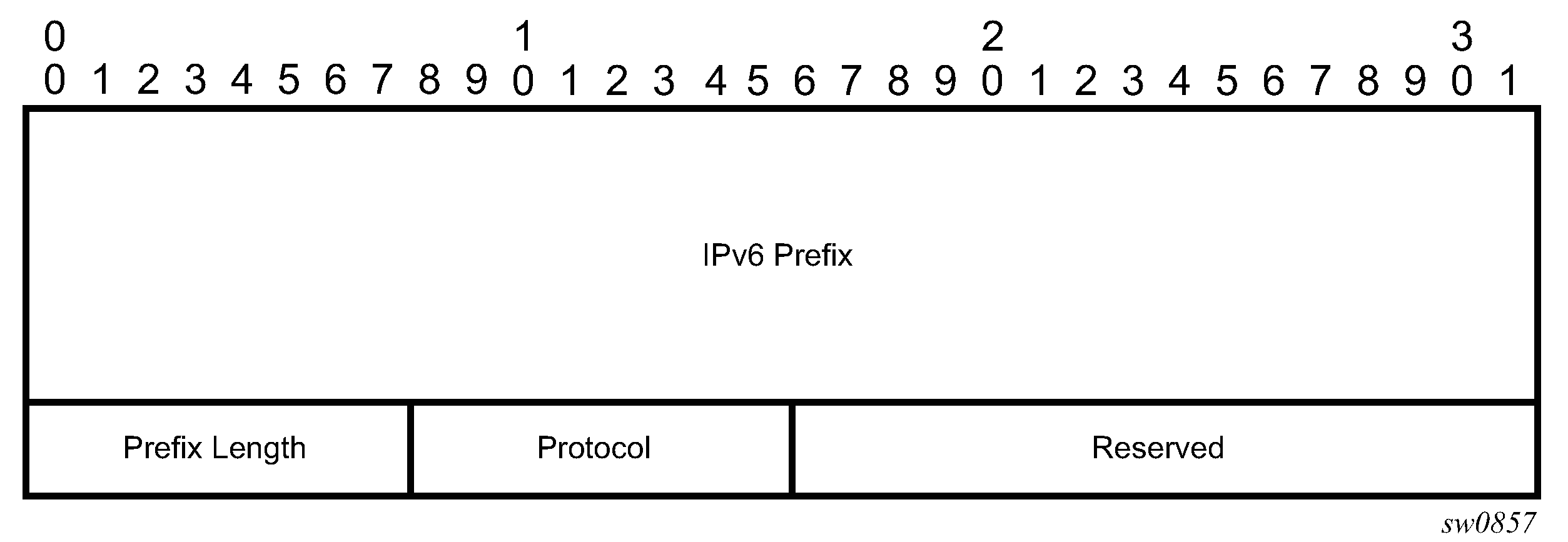
This feature uses the Target FEC stack TLV of type BGP Labeled IPv4 /32 Prefix as defined in RFC 8029.
The following figure shows the structure of the TLV.
The user issues an LSP ping using the following command and specifies a bgp-label type of prefix:
oam lsp-ping bgp-label prefix ip-prefix/mask [src-ip-address ip-address] [fc fc-name [profile {in | out}]] [size octets] [ttl label-ttl] [send-count send-count] [timeout timeout] [interval interval] [path-destination ip-address [interface if-name | next-hop ip-address]] [detail]
This supports BGP label IPv4 prefixes with a prefix length of 32 bits only and supports IPv6 prefixes with a prefix length of 128 bits only.
The path-destination option is used to exercise specific ECMP paths in the network when the LSR performs hashing on the MPLS packet.
Similarly, the user can issue an LSP trace using the following command:
oam lsp-trace bgp-label prefix ip-prefix/mask [src-ip-address ip-address] [fc fc-name [profile {in | out}]] [max-fail no-response-count] [probe-count probes-per-hop] [size octets] [min-ttl min-label-ttl] [max-ttl max-label-ttl] [timeout timeout] [interval interval] [path-destination ip-address [interface if-name | next-hop ip-address]] [detail]
The following is the process to send and respond to an LSP ping or LSP trace packet when the downstream mapping is set to the DSMAP TLV. The detailed procedures with the DDMAP TLV are presented in Using DDMAP TLV in LSP stitching and LSP hierarchy.
The next hop of a BGP labeled route for an IPv4 /32 or IPv6 /128 prefix can be resolved to either an IPv4 or IPv6 transport tunnel. The sender node encapsulates the packet of the Echo Request message with a label stack that consists of the transport label stack as the outer labels and the BGP label as the inner label.
If the packet expires on a node that acts as an LSR for the outer transport LSP, and the node does not have context for the BGP label prefix, then it validates the outer label in the stack. If the validation is successful, it replies the same way that it does when it receives an Echo Request message for an LDP FEC that is stitched to a BGP IPv4 labeled route. That is, it replies with return code 8 ‟Label switched at stack-depth <RSC>”.
An LSR node that is the next hop for the BGP label prefix and the LER node that originated the BGP label prefix have full context for the BGP IPv4 or IPv6 target FEC stack and can perform full validation of it.
If a BGP IPv4 labeled route is stitched to an LDP FEC, the egress LER for the resulting LDP FEC does not have context for the BGP IPv4 target FEC stack in the Echo Request message and replies with return code 4 ‟Replying router has no mapping for the FEC at stack- depth <RSC>”. This behavior is the same as an LDP FEC that is stitched to a BGP IPv4 labeled route when the Echo Request message reaches the egress LER for the BGP prefix.
The responder node must have an IPv4 address to use as the source address of the IPv4 Echo Reply packet. SR OS uses the system interface IPv4 address. When an IPv4 BGP labeled route resolves to an IPv6 next hop and uses an IPv6 transport tunnel, any LSR or LER node that responds to an LSP ping or LSP trace message must have an IPv4 address assigned to the system interface or the reply is not sent. In the latter case, the LSP ping or LSP trace probe times out at the sender node.
Similarly, the responder node must have an IPv6 address assigned to the system interface so that it gets used in the IPv6 Echo Reply packet in the case of a BGP-LU IPv6 labeled route when resolved to an IPv4 or an IPv4-mapped IPv6 next hop, which itself is resolved to an IPv4 transport tunnel.
LSP ping and LSP trace over unnumbered IP interface
LSP ping for Point-to-Point (P2P) and Point-to-Multipoint (P2MP) LSPs can operate over a network using unnumbered links without any changes. LSP trace, P2MP LSP trace, and LDP tree trace are modified such that the unnumbered interface is properly encoded in the downstream mapping (DSMAP/DDMAP) TLV.
In an RSVP P2P or P2MP LSP, the upstream LSR encodes the downstream router ID in the ‟Downstream IP Address” field and the local unnumbered interface index value in the ‟Downstream Interface Address” field of the DSMAP/DDMAP TLV as defined in RFC 8029. Both values are taken from the TE database.
In an LDP unicast FEC or mLDP P2MP FEC, the interface index assigned by the peer LSR is not readily available to the LDP control plane. In this case, the alternative method as defined in RFC 8029 is used. The upstream LSR sets the Address Type to IPv4 Unnumbered, the Downstream IP Address to a value of 127.0.0.1, and the interface index is set to 0. If an LSR receives an echo-request packet with this encoding in the DSMAP/DDMAP TLV, it bypasses interface verification but continues with label validation.
ECMP considerations for LSP ping and LSP trace
When the responder node has multiple equal cost next-hops for an LDP FEC or a BGP label prefix, it replies in the DSMAP TLV with the downstream information of the outgoing interface which is part of the ECMP next-hop set for the prefix.
When BGP labeled route is resolved to an LDP FEC (of the BGP next-hop of the BGP labeled route), ECMP can exist at both the BGP and LDP levels. The following selection of next hop is performed in this case:
-
For each BGP ECMP next-hop of the labeled route, a single LDP next-hop is selected even if multiple LDP ECMP next-hops exist. Thus, the number of ECMP next-hops for the BGP labeled route is equal to the number of BGP next-hops.
-
ECMP for a BGP labeled route is only supported at PE router (BGP label push operation) and not at ABR/ASBR (BGP label swap operation). Thus at an LSR, a BGP labeled route is resolved to a single BGP next-hop which itself is resolved to a single LDP next-hop.
-
LSP trace returns one downstream mapping TLV for each next-hop of the BGP labeled route. Furthermore, it returns exactly the LDP next-hop the datapath programmed for each BGP next-hop.
The following description of the behavior of LSP ping and LSP trace makes a reference to a FEC in a generic way and which can represent an LDP FEC or a BGP labeled route. In addition, the reference to a downstream mapping TLV means either the DSMAP TLV or the DDMAP TLV.
-
If the user initiates an LSP trace of the FEC without the path-destination option specified, the sender node does not include multipath information in the DSMAP TLV in the echo request message (multipath type=0). In this case, the responder node replies with a DSMAP TLV for each outgoing interface, which is part of the ECMP next-hop set for the FEC.
Note: The sender node selects the first DSMAP TLV only for the subsequent echo request message with incrementing TTL. -
If the user initiates an LSP ping of the FEC with the path-destination option specified, the sender node does not include the DSMAP TLV. However, the user can use the interface option, part of the same path-destination option, to direct the echo request message at the sender node to be sent out a specific outgoing interface, which is part of an ECMP path set for the FEC.
-
If the user initiates an LSP trace of the FEC with the path-destination option specified but configured not to include a downstream mapping TLV in the MPLS echo request message using the CLI command downstream-map-tlv {none}, the sender node does not include the DSMAP TLV. However, the user can use the interface option, part of the same path-destination option, to direct the echo request message at the sender node to be sent out a specific outgoing interface which is part of an ECMP path set for the FEC.
-
If the user initiates an LSP trace of the FEC with the path-destination option specified, the sender node includes the multipath information in the Downstream Mapping TLV in the echo request message (multipath type=8). The path-destination option allows the user to exercise a specific path of a FEC in the presence of ECMP. This is performed by having the user enter a specific address from the 127/8 range, which is then inserted in the multipath type 8 information field of the DSMAP TLV. The CPM code at each LSR in the path of the target FEC runs the same hash routine as the datapath and replies in the Downstream Mapping TLV with the specific outgoing interface the packet would have been forwarded to if it did not expire at this node and if DEST IP field in the packet’s header was set to the 127/8 address value inserted in the multipath type 8 information. This hash is based on:
-
the {incoming port, system interface address, label-stack} when the lsr-load-balancing option of the incoming interface is configured to lbl-only. In this case, the 127/8 prefix address entered in the path-destination option is not used to select the outgoing interface. All packets received with the same label stack maps to a single and same outgoing interface.
-
the {incoming port, system interface address, label-stack, SRC/DEST IP fields of the packet} when the lsr-load-balancing option of the incoming interface is configured to lbl-ip. The SRC IP field corresponds to the value entered by the user in the src-ip-address option (default system IP interface address). The DEST IP field corresponds to the 127/8 prefix address entered in the path-destination option. In this case, the CPM code maps the packet, as well as any packet in a sub-range of the entire 127/8 range, to one of the possible outgoing interface of the FEC.
-
the {SRC/DEST IP fields of the packet} when the lsr-load-balancing option of the incoming interface is configured to ip-only. The SRC IP field corresponds to the value entered by the user in the src-ip-address option (default system IP interface address). The DEST IP field corresponds to the 127/8 prefix address entered in the path-destination option. In this case, the CPM code maps the packet, as well as any packet in a sub-range of the entire 127/8 range, to one of the possible outgoing interface of the FEC.
In all preceding cases, the user can use the interface option, part of the same path-destination option, to direct the echo request message at the sender node to be sent out a specific outgoing interface which is part of an ECMP path set for the FEC.
Note: If the user enabled the system-ip-load-balancing hash option (config>system>system-ip-load-balancing), the LSR hashing is modified by applying the system IP interface, with differing bit-manipulation, to the hash of packets of all three options (lbl-only, lbl-ip, ip-only). This system level option enhances the LSR packet distribution such that the probability of the same flow selecting the same ECMP interface index or LAG link index at two consecutive LSR nodes is minimized. -
-
The ldp-treetrace tool always uses the multipath type=8 and inserts a range of 127/8 addresses instead of a single address in order multiple ECMP paths of an LDP FEC. As such, it behaves the same way as the lsp-trace with the path-destination option enabled described in the preceding sections.
-
The path-destination option can also be used to exercise a specific ECMP path of an LDP FEC, which is tunneled over a RSVP LSP or of an LDP FEC stitched to a BGP FEC in the presence of BGP ECMP paths. The user must, however, enable the use of the new DDMAP TLV either globally (config>test-oam>mpls-echo-request-downstream-map ddmap) or within the specific ldp-treetrace or lsp-trace test (downstream-map-tlv ddmap option).
LSP ping for RSVP P2MP LSP (P2MP)
The P2MP LSP ping implementation complies with RFC 6425, Detecting Data Plane Failures in Point-to-Multipoint Multiprotocol Label Switching (MPLS) - Extensions to LSP Ping.
An LSP ping can be generated by entering the following OAM command:
oam p2mp-lsp-ping lsp-name [p2mp-instance instance-name [s2l-dest-addr ip-address [...up to 5 max]]] [fc fc-name [profile {in | out}]] [size octets] [ttl label-ttl] [timeout timeout] [detail]The Echo Request message is sent on the active P2MP instance and is replicated in the datapath over all branches of the P2MP LSP instance. By default, all egress LER nodes that are leaves of the P2MP LSP instance replies to the Echo Request message.
The user can reduce the scope of the Echo Reply messages by explicitly entering a list of addresses for the egress LER nodes that are required to reply. A maximum of five addresses can be specified in a single execution of the p2mp-lsp-ping command. If all five egress LER nodes are router nodes, they can parse the list of egress LER addresses and reply. RFC 6425 specifies that only the top address in the P2MP egress identifier TLV must be inspected by an egress LER. When interoperating with other implementations, the router egress LER responds if its address is anywhere in the list. If another vendor implementation is the egress LER, only the egress LER matching the top address in the TLV may respond.
If the user enters the same egress LER address multiple times in a single p2mp-lsp-ping command, the head-end node displays a response to a single one and displays a single error warning message for the duplicate ones. When queried over SNMP, the head-end node issues a single response trap; no traps are issued for the duplicates.
The timeout parameter should be set to the time it would take to get a response from all probed leaves under no failure conditions. For that purpose, its range extends to 120 seconds for a p2mp-lsp-ping from a 10 second lsp-ping for P2P LSP. The default value is 10 seconds.
The router head-end node displays a ‟Send_Fail” error when a specific S2L path is down only if the user explicitly listed the address of the egress LER for this S2L in the ping command.
Similarly, the router head-end node displays the timeout error when no response is received for an S2L after the expiry of the timeout timer only if the user explicitly listed the address of the egress LER for this S2L in the ping command.
The user can configure a specific value of the ttl parameter to force the Echo Request message to expire on a router branch node or a bud LSR node. The latter replies with a downstream mapping TLV for each branch of the P2MP LSP in the Echo Reply message.
If the router ingress LER node receives the new multipath type field with the list of egress LER addresses in an Echo Reply message from another vendor implementation, it ignores but does not cause an error in processing the downstream mapping TLV.
If the ping expires at an LSR node that is performing a remerge or crossover operation in the datapath between two or more ILMs of the same P2MP LSP, there is an echo reply message for each copy of the Echo Request message received by this node.
The output of the p2mp-lsp-ping command without the detail parameter specified provides a high-level summary of error codes or success codes received.
The output of the command with the detail parameter specified displays a line for each replying node as in the output of the LSP ping for a P2P LSP.
The display is delayed until all responses are received or the timer configured in the timeout parameter has expired. No other CLI commands can be entered while waiting for the display. A control-C (^C) command aborts the ping operation.
For more information about P2MP, see the 7705 SAR Gen 2 MPLS Guide.
LSP trace for RSVP P2MP LSP
The P2MP LSP trace is in accordance with RFC 6425. Generate an LSP trace using the following OAM command.
oam p2mp-lsp-trace lsp-name p2mp-instance instance-name s2l-dest-address ip-address [fc fc-name [profile {in | out}]] [size octets] [max-fail no-response-count] [probe-count probes-per-hop] [min-ttl min-label-ttl] [max-ttl max-label-ttl] [timeout timeout] [interval interval] [detail]The LSP trace capability allows the user to trace a single S2L path of a P2MP LSP. Its operation is similar to that of the p2mp-lsp-ping command but the sender of the echo reply request message includes the downstream mapping TLV to request the downstream branch information from a branch LSR or bud LSR. The branch LSR or bud LSR then also includes the downstream mapping TLV to report the information about the downstream branches of the P2MP LSP. An egress LER does not include this TLV in the echo response message.
The probe-count parameter operates in the same way as in LSP trace on a P2P LSP. It represents the maximum number of probes sent per TTL value before giving up on receiving the echo reply message. If a response is received from the traced node before reaching the maximum number of probes, no more probes are sent for the same TTL. The sender of the echo request then increments the TTL and uses the information it received in the downstream mapping TLV to start sending probes to the node downstream of the last node that replied. This process continues until the egress LER for the traced S2L path replied.
Because the command traces a single S2L path, the timeout and interval parameters keep the same value range as in LSP trace for a P2P LSP.
The P2MP LSP trace makes use of the Downstream Detailed Mapping (DDMAP) TLV. The following excerpt from RFC 6424 details the format of the new DDMAP TLV entered in the path-destination belongs to one of the possible outgoing interfaces of the FEC.
       0                                1                               2
                   3
        0 1  2  3 4 5  6 7  8 9  0 1  2 3  4 5  6  7 8 9  0 1  2 3  4  5 6  7 8  9 0
 1
      +-+-+-+-+-+-+-+-+-+-+-+-+-+-+-+-+-+-+-+-+-+-+-+-+-+-+-+-+-+-+-+-+
      |              MTU                            | Address Type    |    DS Flags
      |
      +-+-+-+-+-+-+-+-+-+-+-+-+-+-+-+-+-+-+-+-+-+-+-+-+-+-+-+-+-+-+-+-+
      |               Downstream Address (4 or 16 octets)
      |
      +-+-+-+-+-+-+-+-+-+-+-+-+-+-+-+-+-+-+-+-+-+-+-+-+-+-+-+-+-+-+-+-+
      |         Downstream Interface Address (4 or 16 octets)
      |
      +-+-+-+-+-+-+-+-+-+-+-+-+-+-+-+-+-+-+-+-+-+-+-+-+-+-+-+-+-+-+-+-+
      |  Return Code  | Return Subcode    |        Subtlv Length
      |
      +-+-+-+-+-+-+-+-+-+-+-+-+-+-+-+-+-+-+-+-+-+-+-+-+-+-+-+-+-+-+-+-+
      .
                           .
      .                      List of SubTLVs

      .
                           .
      +-+-+-+-+-+-+-+-+-+-+-+-+-+-+-+-+-+-+-+-+-+-+-+-+-+-+-+-+-+-+-+-+
The Downstream Detailed Mapping TLV format is derived from the Downstream Mapping (DSMAP) TLV format. The key change is that variable length and optional fields have been converted into sub-TLVs. The fields have the same use and meaning as in RFC 8029.
Similar to P2MP LSP ping, an LSP trace probe results on all egress LER nodes eventually receiving the echo request message but only the traced egress LER node replies to the last probe.
As well, any branch LSR node or bud LSR node in the P2MP LSP tree may receive a copy of the echo request message with the TTL in the outer label expiring at this node. However, only a branch LSR or bud LSR that has a downstream branch over which the traced egress LER is reachable must respond.
When a branch LSR or BUD LSR node responds to the sender of the echo request message, it sets the global return code in the echo response message to RC=14 - "See DDMAP TLV for Return Code and Return Sub-Code" and the return code in the DDMAP TLV corresponding to the outgoing interface of the branch used by the traced S2L path to RC=8 - "Label switched at stack-depth <RSC>".
Because a single egress LER address, for example an S2L path, can be traced, the branch LSR or bud LSR node sets the multipath type of zero in the downstream mapping TLV in the echo response message as no egress LER address need to be included.
LSP trace behavior when S2L path traverses a remerge node
When a 7705 SAR Gen 2 LSR performs a remerge of one or more ILMs of the P2MP LSP to which the traced S2L sub-LSP belongs, it may block the ILM over which the traced S2L resides. This causes the trace to either fail or to succeed with a missing hop.
The following is an example of this behavior.
S2L1 and S2L2 use ILMs that remerge at node B. Depending on which ILM is blocked at B, the TTL=2 probe either yields two responses or times out.
S2L1 = ACBDF (to leaf F)
S2L2 = ABDE (to leaf E)

   A
 /  \
B -- C
|
D
| \
F  E
tracing S2L1 when ILM on interface C-B blocked at node B
For TTL=1, A receives a response from C only as B does not have S2L1 on the ILM on interface A-B.
For TTL=2, assume A receives first the response from B, which indicates a success. It then builds the next probe with TTL=3. B only passes the copy of the message arriving on interface A-B and drops the one arriving on interface C-B (treats it like a data packet because it does not expire at node B). This copy expires at F. However, F returns a DSMappingMismatched error message because the DDMAP TLV was the one provided by node B in TTL=2 step. The trace aborts at this point in time. However, A knows it received a second response from Node D for TTL=2 with a DSMappingMismatched error message.
If A receives the response from D first with the error code, it waits to see if it gets a response from B or it times out. In either case, it logs this status as multiple replies received per probe in the last probe history and aborts the trace.
tracing S2L2 when ILM on interface A-B blocked at node B
For TTL=1, B responds with a success. C does not respond as it does not have an ILM for S2L2.
For TTL=2, B drops the copy coming on interface A-B. It receives a copy coming on interface B-C but drops it as the ILM does not contain S2L2. Node A times out. Next, node A generates a probe with TTL=3 without a DDMAP TLV. This time node D responds with a success and includes its downstream DDMAP TLV to node E. The rest of the path is discovered correctly. The traced path for S2L2 looks like: A-B-(*)-D-E.
The router ingress LER detects a remerge condition when it receives two or more replies to the same probe, such as the same TTL value. It displays the following message to the user regardless if the trace operation successfully reached the egress LER or was aborted earlier: Probe returned multiple responses. Result may be inconsistent.
This warning message indicates the potential of a remerge scenario and that a p2mp-lsp-ping command for this S2L should be used to verify that the S2L path is not defective.
The router ingress LER behavior is to always proceed to the next TTL probe when it receives an OK response to a probe or when it times out on a probe. If, however, it receives replies with an error return code, it must wait until it receives an OK response or it times out. If it times out without receiving an OK reply, the LSP trace must be aborted.
Possible echo reply messages and corresponding ingress LER behaviors are described in Echo reply messages and ingress LER behavior.
| Echo reply message | Ingress LER behavior |
|---|---|
|
One or more error return codes + OK |
Display OK return code. Proceed to next TTL probe. Display warning message at end of trace. |
|
OK + one or more error return codes |
Display OK return code. Proceed to next TTL probe right after receiving the OK reply but keep state that more replies received. Display warning message at end of trace. |
|
OK + OK |
Should not happen for remerge but would continue trace on first OK reply. This is the case when one of the branches of the P2MP LSP is activating the P2P bypass LSP. In this case, the head-end node receives a reply from both a regular P2MP LSR that has the ILM for the traced S2L and from an LSR switching the P2P bypass for other S2Ls. The latter does not have context for the P2MP LSP being tunneled but responds after doing a label stack validation. |
|
One error return code + timeout |
Abort LSP trace and display error code. Ingress LER cannot tell the error occurred of a remerge condition. |
|
More than one error return code + timeout |
Abort LSP trace and display first error code. Display warning message at end of trace. |
|
Timeout on probe without any reply |
Display ‟*” and proceed to next TTL probe. |
Downstream Detailed Mapping (DDMAP) TLV
The Downstream Detailed Mapping (DDMAP) TLV provides the same features as the DSMAP TLV, with the enhancement to trace the details of LSP stitching and LSP hierarchy. The latter is achieved using a sub-TLV of the DDMAP TLV called the FEC stack change sub-TLV. DDMAP TLV shows the structures of these two objects as defined in RFC 6424.
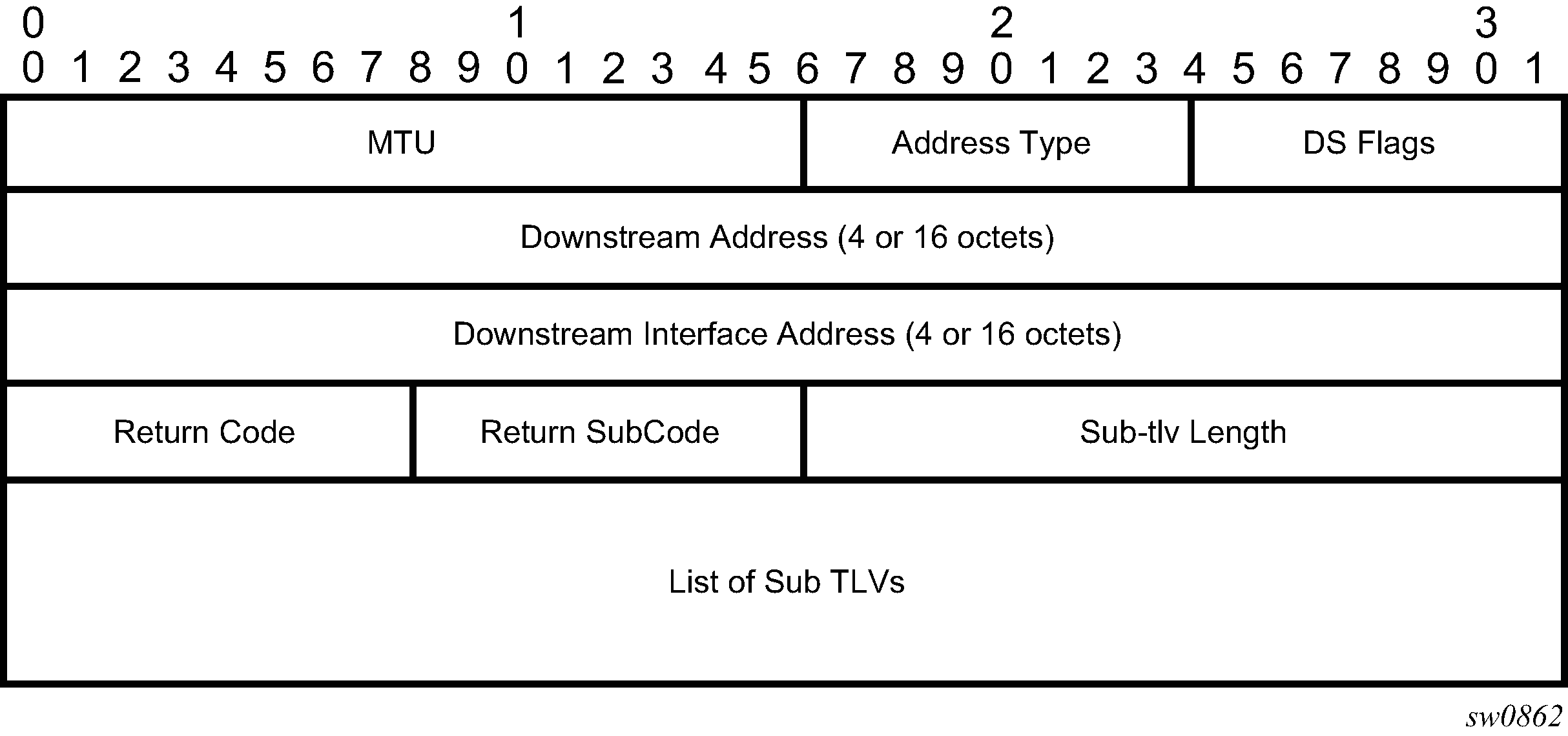
The DDMAP TLV format is derived from the DSMAP TLV format. The key change is that variable length and optional fields have been converted into sub-TLVs. The fields have the same use and meaning as in RFC 8029 as shown in FEC stack change sub-TLV.
The operation type specifies the action associated with the FEC stack change. The following operation types are defined.
Type #     Operation
------     ---------
1          Push
2          Pop
More details on the processing of the fields of the FEC stack change sub-TLV are provided later in this section.
The user can configure which downstream mapping TLV to use globally on a system by using the following command: configure test-oam mpls-echo-request-downstream-map {dsmap | ddmap}
This command specifies which format of the downstream mapping TLV to use in all LSP trace packets and LDP tree trace packets originated on this node. The Downstream Mapping (DSMAP) TLV is the original format in RFC 4379 (obsoleted by RFC 8029) and is the default value. The Downstream Detailed Mapping (DDMAP) TLV is the enhanced format specified in RFC 6424 and RFC 8029.
This command applies to LSP trace of an RSVP P2P LSP, a MPLS-TP LSP, a BGP labeled route, or LDP unicast FEC, and to LDP tree trace of a unicast LDP FEC. It does not apply to LSP trace of an RSVP P2MP LSP, which always uses the DDMAP TLV.
The global DSMAP TLV setting impacts the behavior of both OAM LSP trace packets and SAA test packets of type lsp-trace and is used by the sender node when one of the following events occurs:
-
An SAA test of type lsp-trace is created (not modified) and no value is specified for the per-test downstream-map-tlv {dsmap | ddmap | none} option. In this case the SAA test downstream-map-tlv value defaults to the global mpls-echo-request-downstream-map value.
-
An OAM test of type lsp-trace test is executed and no value is specified for the per-test downstream-map-tlv {dsmap | ddmap | none} option. In this case, the OAM test downstream-map-tlv value defaults to the global mpls-echo-request-downstream-map value.
A consequence of the preceding rules is that a change to the value of the mpls-echo-request-downstream-map option does not affect the value inserted in the downstream mapping TLV of existing tests.
The following are the details of the processing of the DDMAP TLV:
-
When either the DSMAP TLV or the DDMAP TLV is received in an Echo Request message, the responder node includes the same type of TLV in the echo reply message with the correct downstream interface information and label stack information.
-
If an Echo Request message without a Downstream Mapping TLV (DSMAP or DDMAP) expires at a node that is not the egress for the target FEC stack, the responder node always includes the DSMAP TLV in the echo reply message. This can occur in the following cases:
-
The user issues an LSP trace from a sender node with a min-ttl value higher than 1 and a max-ttl value lower than the number of hops to reach the egress of the target FEC stack. This is the sender node behavior when the global configuration or the per-test setting of the Downstream Mapping TLV is set to DSMAP.
-
The user issues a LSP ping from a sender node with a ttl value lower than the number of hops to reach the egress of the target FEC stack. This is the sender node behavior when the global configuration of the Downstream Mapping TLV is set to DSMAP.
-
The behavior in (a) is changed when the global configuration or the per-test setting of the Downstream Mapping TLV is set to DDMAP. The sender node includes in this case the DDMAP TLV with the Downstream IP address field set to the all-routers multicast address as per Section 3.4 of RFC 8029. The responder node then bypasses the interface and label stack validation and replies with a DDMAP TLV with the correct downstream information for the target FEC stack.
-
-
A sender node never includes the DSMAP or DDMAP TLV in an LSP ping message.
Using DDMAP TLV in LSP stitching and LSP hierarchy
In addition to performing the same features as the DSMAP TLV, the DDMAP TLV addresses the following scenarios:
-
Full validation of an LDP IPv4 FEC stitched to a BGP IPv4 labeled route. In this case, the LSP trace message is inserted from the LDP LSP segment or from the stitching point.
-
Full validation of a BGP IPv4 labeled route stitched to an LDP IPv4 FEC. The LSP trace message is inserted from the BGP LSP segment or from the stitching point.
-
Full validation of an LDP IPv4 FEC, which is stitched to a BGP IPv4 labeled route and stitched back into an LDP IPv4 FEC. In this case, the LSP trace message is inserted from the LDP segments or from the stitching points.
-
Full validation of a LDP IPv4 FEC stitched to a SR-ISIS or SR-OSPF IPv4 tunnel.
-
Full validation of an SR-ISIS or SR-OSPF IPv4 tunnel stitched to an LDP IPv4 FEC.
-
Full validation of an LDP FEC tunneled over an RSVP LSP or an SR-TE LSP using LSP trace.
-
Full validation of a BGP IPv4 labeled route or of a BGP IPv6 labeled route (with an IPv4 or an IPv4-mapped IPv6 next-hop) tunneled over an RSVP LSP, an LDP IPv4 FEC, an SR-ISIS IPv4 tunnel, a SR-OSPF IPv4 tunnel, an SR-TE IPV4 LSP, or an IPv4 SR policy.
-
Full validation of a BGP IPv4 labeled route (with an IPv6 next-hop) or a BGP IPv6 labeled route tunneled over an LDP IPv6 FEC, an SR-ISIS IPv6 tunnel, an SR-OSPF3 IPv6 tunnel, an SR-TE IPv6 LSP, or an IPv6 SR policy.
-
Full validation of a BGP IPv6 labeled route (with an IPv4 or an IPv4-mapped IPv6 next-hop) recursively resolved to a BGP IPv4 labeled route which itself is tunneled over an LDP IPv4 FEC, an SR-ISIS IPv4 tunnel, an SR-OSPF IPv4 tunnel, an RSVP-TE LSP, an SR-TE IPv4 LSP, or an IPv4 SR policy.
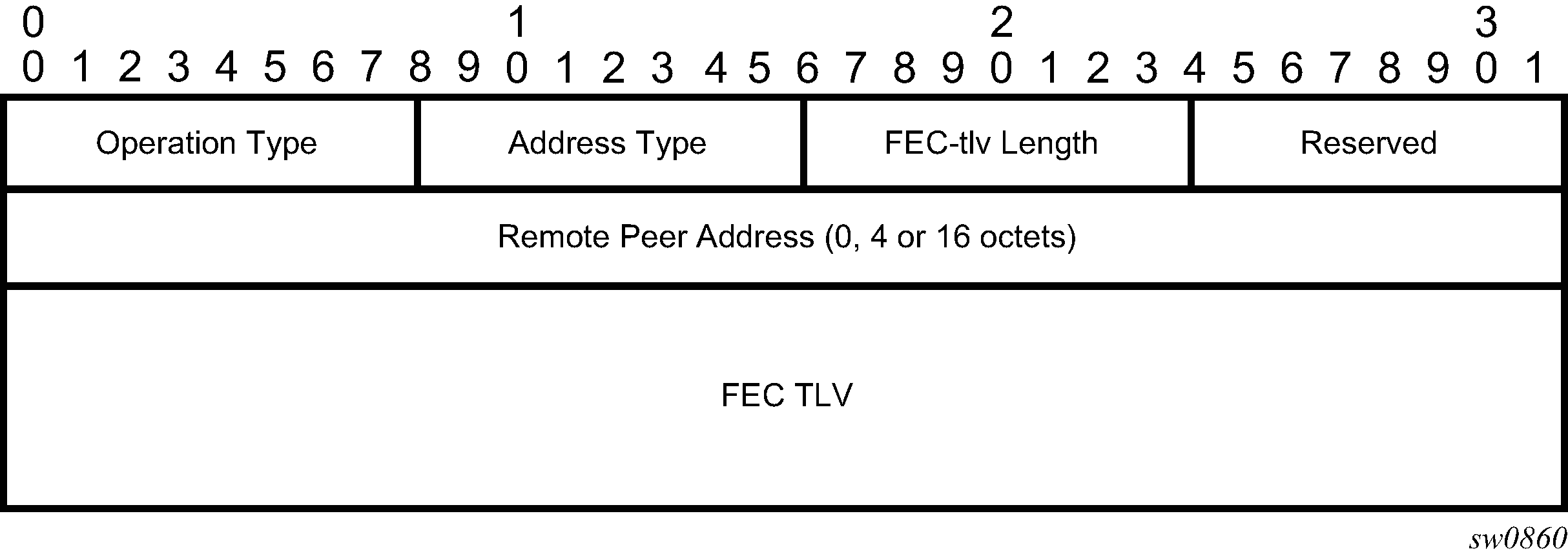
To correctly check a target FEC that is stitched to another FEC (stitching FEC) of the same or a different type, or that is tunneled over another FEC (tunneling FEC), it is necessary for the responding nodes to provide details about the FEC manipulation back to the sender node. This is achieved via the use of the new FEC stack change sub-TLV in the Downstream Detailed Mapping TLV (DDMAP) defined in RFC 6424.
When the user configures the use of the DDMAP TLV on a trace for an LSP that does not undergo stitching or tunneling operations in the network, the procedures at the sender and responder nodes are the same as in the case of the existing DSMAP TLV.
This feature changes the target FEC stack validation procedures at the sender and responder nodes in the case of LSP stitching and LSP hierarchy. These changes pertain to the processing of the new FEC stack change sub-TLV in the new DDMAP TLV and the new return code 15 ‟Label switched with FEC change”. The following is a description of the main changes that are a superset of the rules described in Section 4 of RFC 6424 to allow greater scope of interoperability with other vendor implementations.
Responder node procedures
This section describes responder-node behaviors.
-
As a responder node, the node always inserts a global return code of either:
-
3 ‟Replying router is an egress for the FEC at stack-depth <RSC>”
-
14 ‟See DDMAP TLV for Return Code and Return Subcode”
-
-
When the responder node inserts a global return code of 3, it does not include a DDMAP TLV.
-
When the responder node includes the DDMAP TLV, it inserts a global return code 14 ‟See DDMAP TLV for Return Code and Return Subcode” and does the following:
-
On a success response, includes a return code of 15 in the DDMAP TLV for each downstream that has an FEC stack change TLV.
-
On a success response, includes a return code 8 ‟Label switched at stack-depth <RSC>” in the DDMAP TLV for each downstream if no FEC stack change sub-TLV is present.
-
On a failure response, includes an appropriate error return code in the DDMAP TLV for each downstream.
-
-
A tunneling node indicates that it is pushing an FEC (the tunneling FEC) on top of the target FEC stack TLV by including an FEC stack change sub-TLV in the DDMAP TLV with an FEC operation type value of PUSH. It also includes a return code 15 ‟Label switched with FEC change”.
The downstream interface address and downstream IP address fields of the DDMAP TLV are populated for the pushed FEC. The remote peer address field in the FEC stack change sub-TLV is populated with the address of the control plane peer for the pushed FEC. The label stack sub-TLV provides the full label stack over the downstream interface.
-
A node that is stitching an FEC indicates that it is performing a POP operation for the stitched FEC followed by a PUSH operation for the stitching FEC and potentially one PUSH operation for the transport tunnel FEC. It therefore includes two or more FEC stack change sub-TLVs in the DDMAP TLV in the echo reply message. It also includes a return code 15 ‟Label switched with FEC change”. The downstream interface address and downstream address fields of the DDMAP TLV are populated for the stitching FEC. The remote peer address field in the FEC stack change sub-TLV of type POP is populated with a null value (0.0.0.0). The remote peer address field in the FEC stack change sub-TLV of type PUSH is populated with the address of the control plane peer for the tunneling FEC. The label stack sub-TLV provides the full label stack over the downstream interface.
-
If the responder node is the egress for one or more FECs in the target FEC stack, it must reply with no DDMAP TLV and with a return code 3 ‟Replying router is an egress for the FEC at stack-depth <RSC>”. RSC must be set to the depth of the topmost FEC.
This operation is iterative in a sense that, at the receipt of the Echo Reply message, the sender node pops the topmost FEC from the target stack FEC TLV and resends the echo request message with the same TTL value. The responder node performs exactly the same operation as described in this step until all FECs are popped or until the topmost FEC in the target FEC stack TLV matches the tunneled or stitched FEC. In the latter case, processing of the target FEC stack TLV again follows steps 1 or 2.
Sender node procedures
This section describes sender-node behaviors.
If the Echo Reply message contains the return code 14 ‟See DDMAP TLV for Return Code and Return Subcode” and the DDMAP TLV has a return code 15 ‟Label switched with FEC change”, the sender node adjusts the target FEC stack TLV in the echo request message for the next value of the TTL. This reflects the operation on the current target FEC stack as indicated in the FEC stack change sub-TLV received in the DDMAP TLV of the last Echo Reply message. That is, one FEC is popped at most and one or more FECs are pushed as indicated.
If the Echo Reply message contains the return code 3 ‟Replying router is an egress for the FEC at stack-depth <RSC>”:
-
If the value for the label stack depth specified in the Return Sub-Code (RSC) field is the same as the depth of the current target FEC stack TLV, the sender node considers the trace operation complete and terminates it. A responder node causes this case to occur as per step 6 of Responder node procedures.
-
If the value for the label stack depth specified in the Return Sub-Code (RSC) field is different from the depth of the current target FEC stack TLV, the sender node must continue the LSP trace with the same TTL value, after adjusting the target FEC stack TLV by removing the top FEC. This step continues iteratively until the value for the label stack depth specified in the RSC field is the same as the depth of the current target FEC stack TLV, and in which case, the preceding step is performed. A responder node causes this case to occur as per step 6 of the Responder node procedures.
-
If a DDMAP TLV with or without an FEC stack change sub-TLV is included, the sender node must ignore it and processing is performed as per the first or second preceding steps. A responder node does not cause this case to occur, but a third-party implementation may do so.
-
As a sender node, it can accept an echo-reply message with the global return code of either 14 (with DDMAP TLV return code of 15 or 8) or 15, and correctly process the FEC stack change TLV as per step 1.
If an LSP ping is performed directly to the egress LER of the stitched FEC, there is no DDMAP TLV included in the echo request message, and therefore, the responder node, which is the egress node, still replies with return code 4 ‟Replying router has no mapping for the FEC at stack-depth <RSC>”. This case cannot be resolved with this feature.
OAM support in Segment Routing with MPLS data plane
MPLS OAM supports Segment Routing extensions to lsp-ping and lsp-trace as defined in draft-ietf-mpls-spring-lsp-ping.
Segment Routing (SR) performs both shortest path and source-based routing. When the data plane uses MPLS encapsulation, MPLS OAM tools such as lsp-ping and lsp-trace can be used to check connectivity and trace the path to any midpoint or endpoint of an SR-ISIS, a SR-OSPF shortest path tunnel, or an SR-TE LSP.
The CLI options for lsp-ping and lsp-trace are under OAM and SAA for the following types of Segment Routing tunnels:
SR-ISIS and SR-OSPF node SID tunnels
SR-TE LSP
OAM support in IPv4 or IPv6 SR policies with MPLS data plane
This feature extends the support of LSP ping, LSP trace, and ICMP tunneling probes to IPv4 and IPv6 SR policies.
This feature describes the CLI options for the lsp-ping and lsp-trace commands under the OAM and SAA contexts for the following type of Segment Routing tunnel: sr-policy.
oam lsp-ping sr-policy {color integer <0..4294967295> endpoint ip-address<ipv4/ipv6>} [segment-list id<1..32>] [src-ip-address ip-address] [fc fc-name [profile {in|out}]] [size octets] [ttl label-ttl] [send-count send-count] [timeout timeout] [interval interval] [path-destination ip-address [interface if-name | next-hop ip-address]] [detail]
oam lsp-trace sr-policy {color integer <0..4294967295> endpoint ip-address<ipv4/ipv6>} [segment-list id<1..32>] [src-ip-address ip-address] [fc fc-name [profile {in|out}]] [max-fail no-response-count] [probe-count probes-per-hop] [size octets] [min-ttl min-label-ttl] [max-ttl max-label-ttl] [timeout timeout] [interval interval] [path-destination ip-address [interface if-name | next-hop ip-address]] [downstream-map-tlv {dsmap | ddmap | none}] [detail]
The CLI does not require entry of the SR policy head-end parameter that corresponds to the IPv4 address of the router where the static SR policy is configured or where the BGP NRLRI of the SR policy is sent to by a controller or another BGP speaker. SR OS expects its IPv4 system address in the head-end parameter of both the IPv4 and IPv6 SR policy NLRIs, otherwise, SR OS does not import the NRLI.
The source IPv4 or IPv6 address can be specified to encode in the Echo Request message of the LSP ping or LSP trace packet.
The endpoint command specifies the endpoint of the policy and which can consist of an IPv4 address, and therefore, matching to a SR policy in the IPv4 tunnel-table, or an IPv6 address, and therefore, matching to a SR policy in the IPv6 tunnel-table.
The color command must correspond to the SR policy color attribute that is configured locally in the case of a static policy instance or signaled in the NLRI of the BGP signaled SR policy instance.
The endpoint and color commands test the active path (or instance) of the identified SR policy only.
The lsp-ping and lsp-trace commands can test one segment list at a time by specifying one segment list of the active instance of the policy or active candidate path. In this case, the segment-list id command is configured or segment list 1 is tested by default. The segment-list ID corresponds to the same index that was used to save the SR policy instance in the SR policy database. In the case of a static SR policy, the segment-list ID matches the segment-list index entered in the configuration. In both the static and the BGP SR policies, the segment-list ID matches the index displayed for the segment list in the output of the show command of the policies.
The exercised segment list corresponds to a single SR-TE path with its own NHLFE or super NHLFE in the datapath.
The ICMP tunneling feature support with SR policy is described in ICMP-tunneling operation and does not require additional CLI commands.
LSP ping and LSP trace operation
The following operations are supported with both LSP ping and LSP trace.
-
The lsp-ping and lsp-trace features model the tested segment list as a NIL FEC target FEC stack.
-
Both an IPv4 SR policy (endpoint is an IPv4 address) and IPv6 SR policy (endpoint is an IPv6 address) can potentially contain a mix of IPv4 and IPv6 (node, adjacency, or adjacency set) SIDs in the same segment list or across segment lists of the same policy. While this is not a typical use of the SR policy, it is nonetheless allowed in the IETF standard and supported in SR OS. As a result, the downstream interface and node address information returned in the DSMAP or DDMAP TLV can have a different IP family across the path of the SR policy.
Also, the IPv4 or IPv6 endpoint address can be null (0.0.0.0 or 0::0). This has no impact on the OAM capability.
-
Unlike a SR-TE LSP path, the type of each segment (node, adjacency, or adjacency set) in the SID list may not be known to the sender node, except for the top SID that is validated by the SR policy database and which uses this segment type to resolve the outgoing interface or interfaces and outgoing label or labels to forward the packet out.
-
The NIL FEC type is used to represent each SID in the segment list, including the top SID. The NIL FEC is defined RFC 8029 and has three main applications:
-
Allow the sender node to insert a FEC stack sub-TLV into the target FEC TLV when the FEC type is not known to the sender node (for SIDs of the SR policy except the top SID) or if there is no explicit FEC associated with the label (for a label of a static LSP or a MPLS forwarding policy). This is the application applicable to the SR policy.
Although the sender node knows the FEC type for the top SID in the segment list of a SR policy, the NIL FEC is used for consistency. However, the sender node does all the processing required to look up the top SID as per the procedures of any other explicit FEC type.
-
Allow the sender node to insert a FEC stack sub-TLV into the target FEC stack sub-TLV if a special purpose label (for example, Router Alert) is inserted in the packet's label stack to maintain the correct 1-to-1 mapping of the packet's stacked labels to the hierarchy of FEC elements in the target FEC stack TLV processing at the responder node.
SR OS does not support this application in a sender node role but can process the NIL FEC if received by a third-party implementation.
-
Allow the responder node to hide from the sender node a FEC element that it is pushing or stitching to by adding a NIL FEC TLV with a PUSH or a POP and PUSH (equivalent to a SWAP) operation into the FEC stack change sub-TLV.
SR OS does not support this application in a sender node role but can process the NIL FEC if received by a third-party implementation.
-
-
For lsp-ping, the sender node builds a target FEC Stack TLV which contains a single NIL FEC element corresponding to the last segment of the tested segment list of the SR policy.
-
For lsp-trace, the sender node builds a target FEC Stack TLV which contains a NIL FEC element for each SID in the segment list.
-
To support the processing of the NIL FEC in the context of the SR policy and the applications in RFC 8029, SR OS in a receiver node role performs the following operations:
-
Looks up the label of the NIL FEC in the SR database to match against the SID of a resolved node, a resolved adjacency, a resolved adjacency SET or a binding SID.
-
If a match exists, continues processing of the NIL FEC.
-
Otherwise, looks up the label of the NIL FEC in the Label Manager.
-
If a match exists, processes the FEC as per the POP or SWAP operation provided by the lookup and following the NIL FEC procedures in RFC 8029.
-
Otherwise, fails the validation and send a return code of 3 < Replying router has no mapping for the FEC at stack-depth <RSC>> in the MPLS echo reply message. The sender node fails the probe at this point.
-
-
A SID label associated with a NIL FEC and which is popped at an LSR, acting in a receiver node role, is first looked up. If the label is valid, the processing results in a return code of 3 <Replying router is an egress for the FEC at stack-depth <RSC>>.
A label is valid if the LSR validates it in its Segment Routing (SR) database. Because the LSR does not know the actual FEC type and FEC value, it successfully validates it if the SR database indicates a programmed POP operation with that label for a node SID exists.
-
A SID label associated with a NIL FEC and which is swapped at an LSR, acting in a receiver node role, is first looked up. If the label is valid, the processing results in the return code of 8 Label switched at stack-depth <RSC> as per RFC 8029.
A label is valid if the LSR validates it in its Segment Routing (SR) database. Because the LSR does not know the actual FEC type and FEC value, it successfully validates it if the SR database indicates a programmed SWAP operation with that label for either a node SID, an adjacency SID, an adjacency SET SID, or a binding SID exists.
The swap operation corresponds to swapping the incoming label to an implicit-null label toward the downstream router in the case of an adjacency and toward a set of downstream routers in the case of an adjacency set.
The swap operation corresponds to swapping the incoming label to one or more labels toward a set of downstream routers in the case of a node SID and a binding SID.
-
The lsp-trace command is supported with the inclusion of the DSMAP TLV, the DDMAP TLV, or none of them by the sender node in the Echo Request message. The responder node returns in the DSMAP or DDMAP TLV the downstream interface information along with the egress label and protocol ID that corresponds to the looked up node SID, adjacency SID, adjacency SET SID, or binding SID.
-
When the Target FEC Stack TLV contains more than one NIL FEC element, the responder node that is the termination of a FEC element indicates the FEC POP operation implicitly by replying with a return code of 3 <Replying router is an egress for the FEC at stack-depth <RSC>>. When the sender node gets this reply, the sender node adjusts the Target FEC Stack TLV by stripping the top FEC before sending the next probe for the same TTL value. When the responder node receives the next Echo Request message with the same TTL value from the sender node, the responder node processes the next FEC element in the stack.
-
The responder node performs validation of the top FEC in the target FEC stack TLV provided that the depth of the incoming label stack in the packet's header is strictly higher than the depth of the target FEC stack TLV.
-
The ttl value in lsp-ping context can be set to a value lower than 255 and the responder node replies if the NIL FEC element in the Target FEC Stack TLV corresponds to a node SID resolved at that node. The responder node, however, fails the validation if the NIL FEC element in Target FEC Stack TLV corresponds to adjacency of a remote node. The return code in the echo reply message can be one of: rc=4(NoFECMapping), and rc=10(DSRtrUnmatchLabel).
-
The min-ttl and max-ttl commands in lsp-trace context can be set to values other than default. The min-ttl can, however, properly trace the partial path of a SR policy only if there is not segment termination before the node that corresponds to the min-ttl value. Otherwise, the validation fails and returns an error as the responder node receives a Target FEC Stack depth that is higher than incoming label stack size. The return code in the echo reply message can be one of: rc=4(NoFECMapping), rc=5(DSMappingMismatched), and rc=10(DSRtrUnmatchLabel).
This is true when the downstream-map-tlv option is set to any of ddmap, dsmap, or none values.
ICMP-tunneling operation
The ICMP tunneling feature operates in the same way as in a SR-TE LSP. When the label TTL of a traceroute packet of a core IPv4 or IPv6 route or a VPN IPv4 or VPN IPv6 route expires at an LSR, the latter generates an ICMP reply packet of type=11- (time exceeded) and injects it in the forward direction of the SR policy. When the packet is received by the egress LER or a BGP border router, SR OS performs a regular user packet route lookup in the datapath in the GRT context or in a VPRN context and forwards the packet to the destination. The destination of the packet is the sender of the original packet which TTL expired at the LSR.
SR extensions for lsp-ping and lsp-trace CLI commands
This section describes how MPLS OAM models the SR tunnel types.
An SR shortest path tunnel for SR IS-IS or SR-OSPF uses a single FEC element in the Target FEC stack TLV. The FEC corresponds to the prefix of the node SID in a specific IGP instance.
The following figure shows the format of the IPv4 IGP-prefix segment ID.
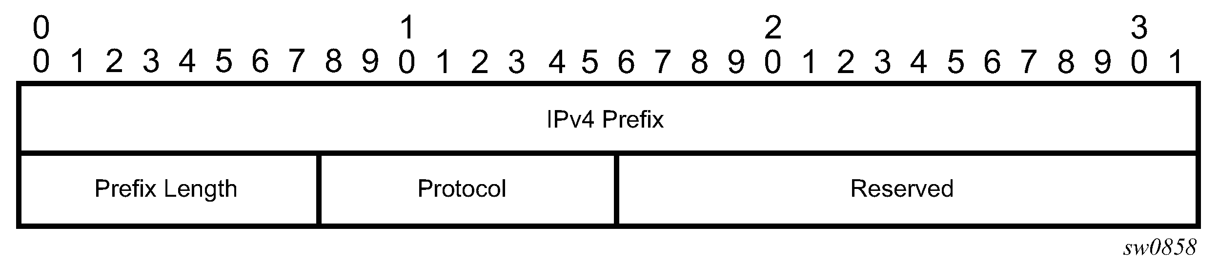
The IPv4 IGP-prefix segment ID consists of the following fields:
IPv4 Prefix
This field is the IPv4 prefix to which the segment ID is assigned. For anycast segment ID, this field is the IPv4 anycast address. If the prefix is shorter than 32 bits, trailing bits must be set to zero.
Prefix Length
This field is one octet and is the length of the prefix in bits (values can be 1 to 32).
Protocol
This field is set to 1 if the IGP protocol is OSPF and set to 2 if the IGP protocol is IS-IS.
The following figure shows the format for the IPv6 IGP-prefix segment ID.
In this format, the fields are as follows:
IPv6 Prefix
This field carries the IPv6 prefix to which the segment ID is assigned. For anycast segment ID, this field carries the IPv4 anycast address. If the prefix is shorter than 128 bits, trailing bits must be set to zero.
Prefix Length
This field is one octet and provides the length of the prefix in bits (values can be 1 to 128).
Protocol
This field is set to 1 if the IGP protocol is OSPF and set to 2 if the IGP protocol is IS-IS.
An SR-TE LSP, as a hierarchical LSP, uses the Target FEC stack TLV, which contains an FEC element for each node SID and for each adjacency SID in the path of the SR-TE LSP. Because the SR-TE LSP does not instantiate state in the LSR, other than the ingress LSR, MPLS OAM is testing a hierarchy of node SID and adjacency SID segments toward the destination of the SR-TE LSP. The format of the node-SID is described previously in this section.
The following figure shows the format of the IGP-Adjacency segment ID.
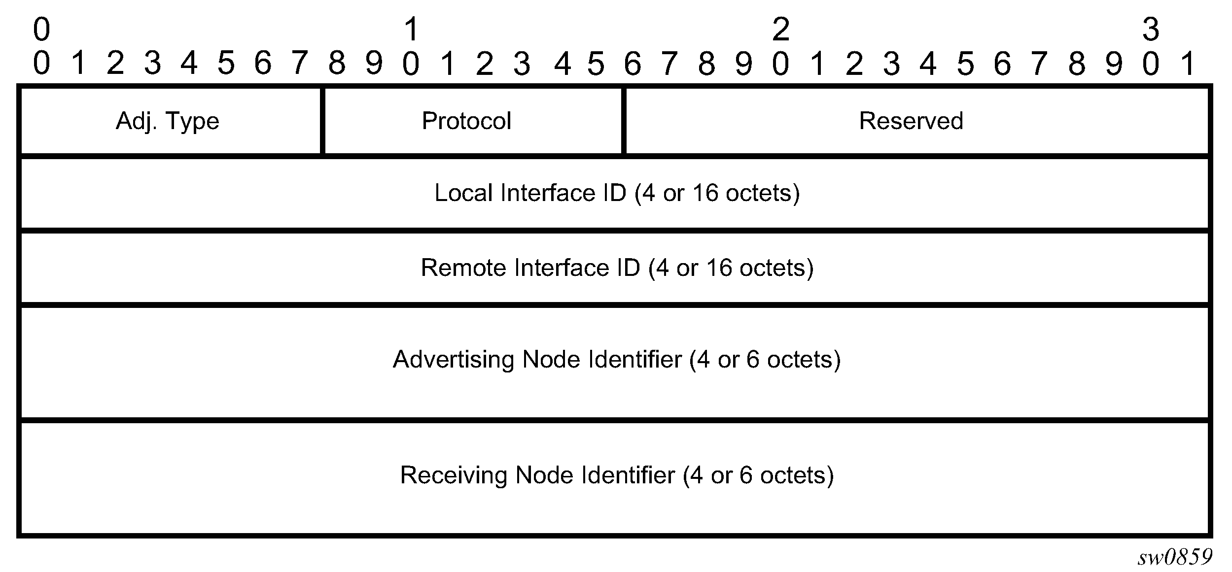
The IGP-Adjacency segment ID consists of the following fields:
Adj. Type (Adjacency Type)
This field is set to 1 when the adjacency segment is parallel adjacency, as defined in section 3.5.1 of I-D.ietf-spring-segment-routing. This field is set to 4 when the adjacency segment is IPv4-based and is not a parallel adjacency. This field is set to 6 when the adjacency segment is IPv6-based and is not a parallel adjacency.
Protocol
This field is set to 1 if the IGP protocol is OSPF and is set to 2 if the IGP protocol is IS-IS.
Local Interface ID
This field is an identifier that is assigned by the local LSR for a link on which the adjacency segment ID is bound. This field is set to local link address (IPv4 or IPv6). If unnumbered, this field uses the 32-bit link identifier defined in RFC 4203 and RFC 5307. If the adjacency segment ID represents parallel adjacencies, as described in section 3.5.1 of I-D.ietf-spring-segment-routing, this field must be set to zero.
Remote Interface ID
This field is an identifier that is assigned by the remote LSR for a link on which the adjacency segment ID is bound. This field is set to the remote (downstream neighbor) link address (IPv4 or IPv6). If unnumbered, the field uses the 32-bit link identifier defined in RFC 4203 and RFC 5307. The adjacency segment ID represents parallel adjacencies, as described in section 3.5.1 of I-D.ietf-spring-segment-routing. This field must be set to zero.
Advertising Node Identifier
This field specifies the advertising node identifier. When the Protocol field is set to 1, the 32 right-most bits represent the OSPF router ID. If the Protocol field is set to 2, this field is the 48-bit IS-IS system ID.
Receiving Node Identifier
This field specifies the downstream node identifier. When the Protocol field is set to 1, the 32 right-most bits represent the OSPF router ID. If the Protocol field is set to 2, this field is the 48-bit IS-IS system ID.
Both lsp-ping and lsp-trace apply to the following contexts:
-
SR-ISIS or SR-OSPF shortest path IPv4 tunnel
-
SR-ISIS or SR-OSPF3 (OSPFv3 instance ID 0-31) shortest path IPv6 tunnel
-
IS-IS SR-TE IPv4 LSP and OSPF SR-TE IPv4 LSP
-
IS-IS SR-TE IPv6 LSP
-
SR-ISIS IPv4 tunnel stitched to an LDP IPv4 FEC
-
BGP IPv4 LSP or BGP IPv6 LSP (with an IPv4 or an IPv4-mapped-IPv6 next-hop) resolved over an SR‑ISIS IPv4 tunnel, an SR-OSPF IPv4 tunnel, or an SR-TE IPv4 LSP. This includes support for BGP LSP across AS boundaries and for ECMP next-hops at the transport tunnel level.
-
BGP IPv4 LSP (with an IPv6 next-hop) or a BGP IPv6 LSP resolved over an SR-ISIS IPv6 tunnel, an SR-OSPF3 IPv6 tunnel, or an SR-TE IPv6 LSP; including support for BGP LSP across AS boundaries and for ECMP next-hops at the transport tunnel level.
-
SR-ISIS or SR-OSPF IPv4 tunnel resolved over IGP IPv4 shortcuts using RSVP-TE LSPs
-
SR-ISIS IPv6 tunnel resolved over IGP IPv4 shortcuts using RSVP-TE LSPs
-
LDP IPv4 FEC resolved over IGP IPv4 shortcuts using SR-TE LSPs
Operations on SR IS-IS or SR-OSPF tunnels
The following operations apply to the lsp-ping and lsp-trace commands:
The sender node builds the Target FEC stack TLV with a single FEC element corresponding to the node SID of the destination of the SR IS-IS or SR-OSPF tunnel.
-
A node SID label that is swapped at an LSR results in the return code of 8, ‟Label switched at stack-depth <RSC>” as defined in RFC 8029.
A node SID label that is popped at an LSR results in return code 3, ‟Replying router is an egress for the FEC at stack-depth <RSC>”.
The lsp-trace command is supported with the inclusion of the DSMAP TLV, the DDMAP TLV, or none values (when none is configured, no Map TLV is sent). The downstream interface information is returned, along with the egress label for the node SID tunnel and the protocol that resolved the node SID at the responder node.
The following figure shows an example topology for an lsp-ping and lsp-trace command for SR IS-IS node SID tunnel.
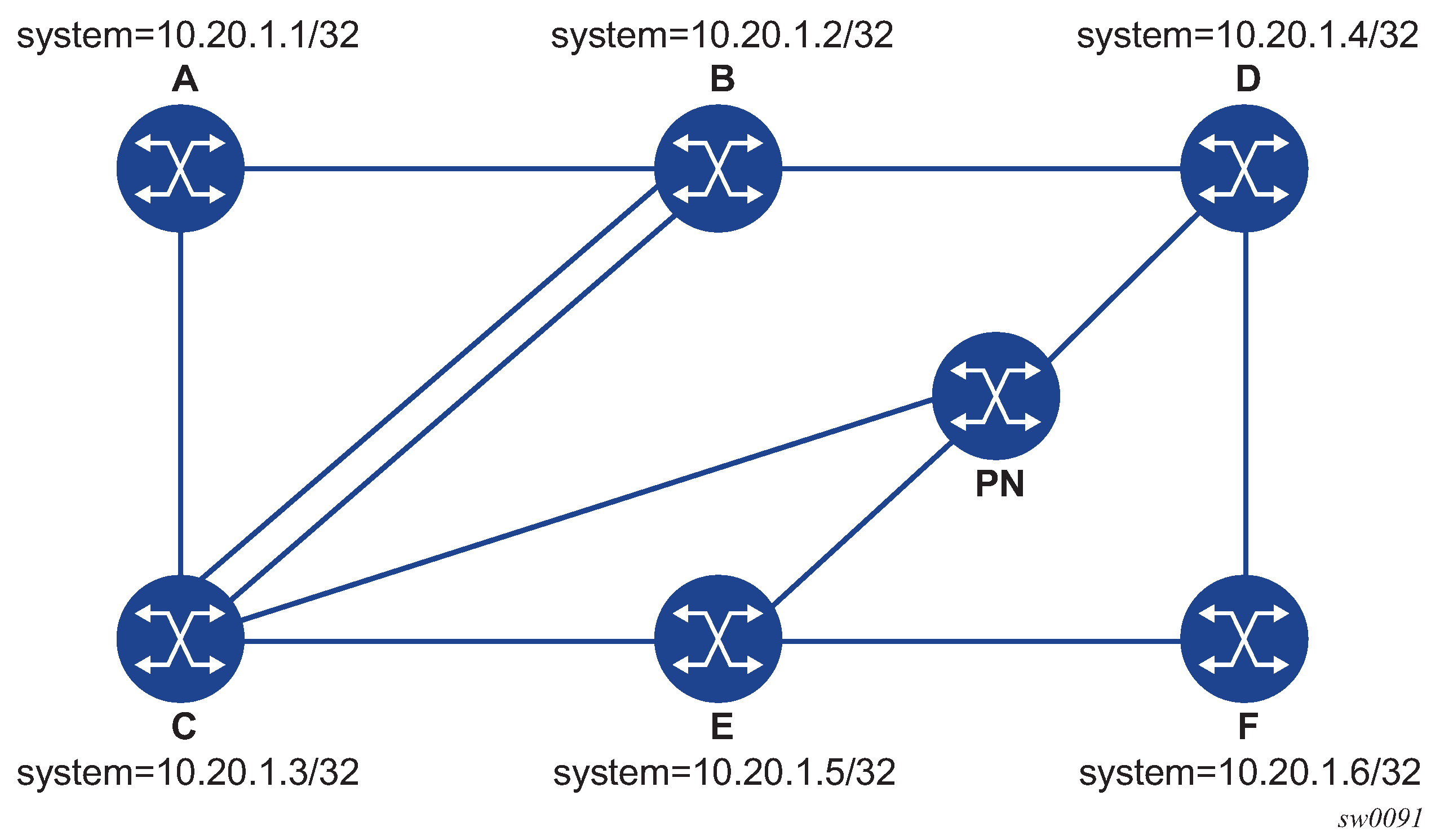
The following examples use the sample topology shown in the preceding figure.
lsp-ping command on DUT-A for target node SID of DUT-F (DDMAP TLV)
*A:Dut-A# oam lsp-ping sr-isis prefix 10.20.1.6/32 igp-instance 0 detail
LSP-PING 10.20.1.6/32: 80 bytes MPLS payload
Seq=1, send from intf int_to_B, reply from 10.20.1.6
       udp-data-len=32 ttl=255 rtt=1220324ms rc=3 (EgressRtr)
---- LSP 10.20.1.6/32 PING Statistics ----
1 packets sent, 1 packets received, 0.00% packet loss
round-trip min = 1220324ms, avg = 1220324ms, max = 1220324ms, stddev = 0.000ms
lsp-trace command on DUT-A for a target node SID of DUT-F (DSMAP TLV)
*A:Dut-A# oam lsp-trace sr-isis prefix 10.20.1.6/32 igp-instance 0 detail
lsp-trace to 10.20.1.6/32: 0 hops min, 0 hops max, 108 byte packets
1  10.20.1.2  rtt=1220323ms rc=8(DSRtrMatchLabel) rsc=1
     DS 1: ipaddr=10.10.4.4 ifaddr=10.10.4.4 iftype=ipv4Numbered MRU=1496
           label[1]=26406 protocol=6(ISIS)
2  10.20.1.4  rtt=1220323ms rc=8(DSRtrMatchLabel) rsc=1
     DS 1: ipaddr=10.10.9.6 ifaddr=10.10.9.6 iftype=ipv4Numbered MRU=1496
           label[1]=26606 protocol=6(ISIS)
3  10.20.1.6  rtt=1220324ms rc=3(EgressRtr) rsc=1
lsp-trace command on DUT-A for target node SID of DUT-F (DDMAP TLV)
*A:Dut-A# oam lsp-trace sr-isis prefix 10.20.1.6/32 igp-instance 0 downstream-map-
tlv ddmap detail
lsp-trace to 10.20.1.6/32: 0 hops min, 0 hops max, 108 byte packets
1  10.20.1.2  rtt=1220323ms rc=8(DSRtrMatchLabel) rsc=1
     DS 1: ipaddr=10.10.4.4 ifaddr=10.10.4.4 iftype=ipv4Numbered MRU=1496
           label[1]=26406 protocol=6(ISIS)
2  10.20.1.4  rtt=1220324ms rc=8(DSRtrMatchLabel) rsc=1
     DS 1: ipaddr=10.10.9.6 ifaddr=10.10.9.6 iftype=ipv4Numbered MRU=1496
           label[1]=26606 protocol=6(ISIS)
3  10.20.1.6  rtt=1220324ms rc=3(EgressRtr) rsc=1
Operations on SR-TE LSP
The following operations apply to the lsp-ping and lsp-trace commands:
The sender node builds a target FEC stack TLV that contains FEC elements.
For lsp-ping, the Target FEC stack TLV contains a single FEC element that corresponds to the last segment; that is, a node SID or an adjacency SID of the destination of the SR-TE LSP.
For lsp-trace, the Target FEC stack TLV contains an FEC element for each node SID and for each adjacency SID in the path of the SR-TE LSP, including that of the destination of the SR-TE LSP.
A node SID label popped at an LSR results in return code 3, ‟Replying router is an egress for the FEC at stack-depth <RSC>”.
An adjacency SID label popped at an LSR results in return code 3, ‟Replying router is an egress for the FEC at stack-depth <RSC>”.
-
A node SID label that is swapped at an LSR results in the return code of 8, "Label switched at stack-depth <RSC>" as defined in RFC 8029, Detecting Multiprotocol Label Switched (MPLS) Data-Plane Failures.
An adjacency SID label that is swapped at an LSR results in the return code of 8, "Label switched at stack-depth <RSC>" as defined in RFC 8029; for example, in SR OS, ‟rc=8(DSRtrMatchLabel) rsc=1”.
The lsp-trace command is supported with the inclusion of the DSMAP TLV, the DDMAP TLV, or none values (when none is configured, no Map TLV is sent). The downstream interface information is returned, along with the egress label for the node SID tunnel, or the adjacency SID tunnel of the current segment and the protocol that resolved the tunnel at the responder node.
When the Target FEC stack TLV contains more than one FEC element, the responder node that is the termination of one node or adjacency SID segment SID pops its own SID in the first operation. When the sender node receives this reply, it adjusts the Target FEC stack TLV by stripping the top FEC before sending the probe for the next TTL value. When the responder node receives the next echo request message with the same TTL value from the sender node for the next node SID or adjacency SID segment in the stack, it performs a swap operation to that next segment.
When the path of the SR-TE LSP is computed by the sender node, the hop-to-label translation tool returns the IGP instance that was used to determine the labels for each hop of the path. When the path of an SR-TE LSP is computed by a PCE, the protocol ID is not returned in the SR-ERO by PCEP. In this case, the sender node performs a lookup in the SR module for the IGP instance that resolved the first segment of the path. In both cases, the determined IGP is used to encode the Protocol ID field of the node SID or adjacency SID in each of the FEC elements of a Target FEC stack TLV.
The responder node performs validation of the top FEC in the Target FEC stack TLV, provided that the depth of the incoming label stack in the packet header is higher than the depth of the Target FEC stack TLV.
TTL values can be changed.
The ttl value in the lsp-ping command can be set to a value lower than 255, and the responder node replies if the FEC element in the Target FEC stack TLV corresponds to a node SID resolved at that node. The responder node, however, fails the validation if the FEC element in the Target FEC stack TLV is the adjacency of a remote node. The return code in the Echo Reply message can be one of: ‟rc=4(NoFECMapping)” or ‟rc=10(DSRtrUnmatchLabel)”.
The min-ttl and max-ttl values in the lsp-trace command can be set to values other than default. The minimum TTL value can, however, trace the partial path of an SR-TE LSP only if there is no segment termination before the node that corresponds to the minimum TTL value. Otherwise, it fails validation and returns an error because the responder node receives a target FEC stack depth that is higher than the incoming label stack size. The return code in the Echo Reply message can be one of: ‟rc=4(NoFECMapping)”, ‟rc=5(DSMappingMismatched)”, or ‟rc=10(DSRtrUnmatchLabel)”.
This is true when the downstream-map-tlv option is set to any of the ddmap, dsmap, or none values.
The following figure shows an example topology for the lsp-ping and lsp-trace commands for SR-TE LSPs.
The following are examples show outputs for the lsp-ping and lsp-trace commands for SR-TE LSPs, based on the sample topology shown in the preceding figure. Example 1 uses a path with strict hops, each corresponding to an adjacency SID, while Example 2 uses a path with loose hops, each corresponding to a node SID.
1
The following output is an example of lsp-ping and lsp-trace on DUT-A for strict-hop adjacency SID SR-TE LSP, where:
-
source = DUT-A
-
destination = DUT-F
-
path = A-B, B-C, C-E, E-D, D-F
*A:Dut-A# oam lsp-ping sr-te "srteABCEDF" detail
LSP-PING srteABCEDF: 96 bytes MPLS payload
Seq=1, send from intf int_to_B, reply from 10.20.1.6
       udp-data-len=32 ttl=255 rtt=1220325ms rc=3 (EgressRtr)
---- LSP srteABCEDF PING Statistics ----
1 packets sent, 1 packets received, 0.00% packet loss
round-trip min = 1220325ms, avg = 1220325ms, max = 1220325ms, stddev = 0.000ms
*A:Dut-A# oam lsp-trace sr-te "srteABCEDF" downstream-map-tlv ddmap detail
lsp-trace to srteABCEDF: 0 hops min, 0 hops max, 252 byte packets
1  10.20.1.2  rtt=1220323ms rc=3(EgressRtr) rsc=5
1  10.20.1.2  rtt=1220322ms rc=8(DSRtrMatchLabel) rsc=4
     DS 1: ipaddr=10.10.33.3 ifaddr=10.10.33.3 iftype=ipv4Numbered MRU=1520
           label[1]=3 protocol=6(ISIS)
           label[2]=262135 protocol=6(ISIS)
           label[3]=262134 protocol=6(ISIS)
           label[4]=262137 protocol=6(ISIS)
2  10.20.1.3  rtt=1220323ms rc=3(EgressRtr) rsc=4
2  10.20.1.3  rtt=1220323ms rc=8(DSRtrMatchLabel) rsc=3
     DS 1: ipaddr=10.10.5.5 ifaddr=10.10.5.5 iftype=ipv4Numbered MRU=1496
           label[1]=3 protocol=6(ISIS)
           label[2]=262134 protocol=6(ISIS)
           label[3]=262137 protocol=6(ISIS)
3  10.20.1.5  rtt=1220325ms rc=3(EgressRtr) rsc=3
3  10.20.1.5  rtt=1220325ms rc=8(DSRtrMatchLabel) rsc=2
     DS 1: ipaddr=10.10.11.4 ifaddr=10.10.11.4 iftype=ipv4Numbered MRU=1496
           label[1]=3 protocol=6(ISIS)
           label[2]=262137 protocol=6(ISIS)
4  10.20.1.4  rtt=1220324ms rc=3(EgressRtr) rsc=2
4  10.20.1.4  rtt=1220325ms rc=8(DSRtrMatchLabel) rsc=1
     DS 1: ipaddr=10.10.9.6 ifaddr=10.10.9.6 iftype=ipv4Numbered MRU=1496
           label[1]=3 protocol=6(ISIS)
5  10.20.1.6  rtt=1220325ms rc=3(EgressRtr) rsc=1
2
The following output is an example of lsp-ping and lsp-trace on DUT-A for a loose-hop node SID SR-TE LSP, where:
-
source = DUT-A
-
destination = DUT-F
-
path = A, B, C, E
*A:Dut-A# oam lsp-ping sr-te "srteABCE_loose" detail
LSP-PING srteABCE_loose: 80 bytes MPLS payload
Seq=1, send from intf int_to_B, reply from 10.20.1.5
       udp-data-len=32 ttl=255 rtt=1220324ms rc=3 (EgressRtr)
---- LSP srteABCE_loose PING Statistics ----
1 packets sent, 1 packets received, 0.00% packet loss
round-trip min = 1220324ms, avg = 1220324ms, max = 1220324ms, stddev = 0.000ms
*A:Dut-A# oam lsp-trace sr-te "srteABCE_loose" downstream-map-tlv ddmap detail
lsp-trace to srteABCE_loose: 0 hops min, 0 hops max, 140 byte packets
1  10.20.1.2  rtt=1220323ms rc=3(EgressRtr) rsc=3
1  10.20.1.2  rtt=1220322ms rc=8(DSRtrMatchLabel) rsc=2
     DS 1: ipaddr=10.10.3.3 ifaddr=10.10.3.3 iftype=ipv4Numbered MRU=1496
           label[1]=26303 protocol=6(ISIS)
           label[2]=26305 protocol=6(ISIS)
     DS 2: ipaddr=10.10.12.3 ifaddr=10.10.12.3 iftype=ipv4Numbered MRU=1496
           label[1]=26303 protocol=6(ISIS)
           label[2]=26305 protocol=6(ISIS)
     DS 3: ipaddr=10.10.33.3 ifaddr=10.10.33.3 iftype=ipv4Numbered MRU=1496
           label[1]=26303 protocol=6(ISIS)
           label[2]=26305 protocol=6(ISIS)
2  10.20.1.3  rtt=1220323ms rc=3(EgressRtr) rsc=2
2  10.20.1.3  rtt=1220323ms rc=8(DSRtrMatchLabel) rsc=1
     DS 1: ipaddr=10.10.5.5 ifaddr=10.10.5.5 iftype=ipv4Numbered MRU=1496
           label[1]=26505 protocol=6(ISIS)
     DS 2: ipaddr=10.10.11.5 ifaddr=10.10.11.5 iftype=ipv4Numbered MRU=1496
           label[1]=26505 protocol=6(ISIS)
3  10.20.1.5  rtt=1220324ms rc=3(EgressRtr) rsc=1
Operations on an SR IS-IS tunnel stitched to an LDP FEC
The following operations apply to the lsp-ping and lsp-trace commands:
The lsp-ping tool works only when the responder node is in the same domain (SR or LDP) as the sender node.
The lsp-ping tool works throughout the LDP and SR domains. When used with the DDMAP TLV, lsp-trace provides the details of the SR-LDP stitching operation at the boundary node. The boundary node as a responder node replies with the FEC stack change TLV, which contains two operations:
a PUSH operation of the SR (LDP) FEC in the LDP-to-SR (SR-to-LDP) direction
a POP operation of the LDP (SR) FEC in the LDP-to-SR (SR-to-LDP) direction
The ICMP tunneling feature is supported for an SR IS-IS tunnel stitched to an LDP FEC.
lsp-trace command with the DDMAP TLV for LDP-to-SR direction (symmetric topology LDP-SR-LDP)
*A:Dut-E# oam lsp-trace prefix 10.20.1.2/32 detail downstream-map-tlv ddmap
lsp-trace to 10.20.1.2/32: 0 hops min, 0 hops max, 108 byte packets
1  10.20.1.3  rtt=3.25ms rc=15(LabelSwitchedWithFecChange) rsc=1
     DS 1: ipaddr=10.10.3.2 ifaddr=10.10.3.2 iftype=ipv4Numbered MRU=1496
           label[1]=26202 protocol=6(ISIS)
           fecchange[1]=POP  fectype=LDP IPv4 prefix=10.20.1.2 remotepeer=0.0.0.0
Unknown)
           fecchange[2]=PUSH fectype=SR Ipv4 Prefix prefix=10.20.1.2 remotepeer=10.1
0.3.2
2  10.20.1.2  rtt=4.32ms rc=3(EgressRtr) rsc=1
*A:Dut-E#
lsp-trace command with the DDMAP TLV for SR-to-LDP direction (symmetric topology LDP-SR-LDP)
*A:Dut-B# oam lsp-trace prefix 10.20.1.5/32 detail downstream-map-tlv ddmap sr-isis
lsp-trace to 10.20.1.5/32: 0 hops min, 0 hops max, 108 byte packets
1  10.20.1.3  rtt=2.72ms rc=15(LabelSwitchedWithFecChange) rsc=1
     DS 1: ipaddr=10.11.5.5 ifaddr=10.11.5.5 iftype=ipv4Numbered MRU=1496
           label[1]=262143 protocol=3(LDP)
           fecchange[1]=POP  fectype=SR Ipv4 Prefix prefix=10.20.1.5 remotepeer=0.0.
0.0 (Unknown)
           fecchange[2]=PUSH fectype=LDP IPv4 prefix=10.20.1.5 remotepeer=10.11.5.5
2  10.20.1.5  rtt=4.43ms rc=3(EgressRtr) rsc=1
Operations on a BGP IPv4 LSP resolved over an SR IS-IS IPv4 tunnel, SR-OSPF IPv4 tunnel, or SR-TE IPv4 LSP
The operations of LSP ping and LSP trace of a BGP IPv4 LSP resolved over an SR IS-IS IPv4 tunnel, an SR-OSPF IPv4 tunnel, or an SR-TE IPv4 LSP are enhanced. The enhancement reports the full set of ECMP next hops for the transport tunnel at both ingress PE and at the ABR or ASBR. The list of downstream next hops is reported in the DSMAP or DDMAP TLV.
When the user initiates an LSP trace of the BGP IPv4 LSP with the path-destination option specified, the CPM hash code, at the responder node, selects the outgoing interface to be returned in DSMAP or DDMAP. This decision is based on the module operation of the hash value on the label stack or the IP headers (where the DST IP is replaced by the specific 127/8 prefix address in the multipath type 8 field of the DSMAP or DDMAP) of the echo request message and the number of outgoing interfaces in the ECMP set.
The following figure shows an example topology used in the subsequent BGP over SR-OSPF, BGP over SR-TE (OSPF), BGP over SR IS-IS, and BGP over SR-TE (IS-IS) examples.
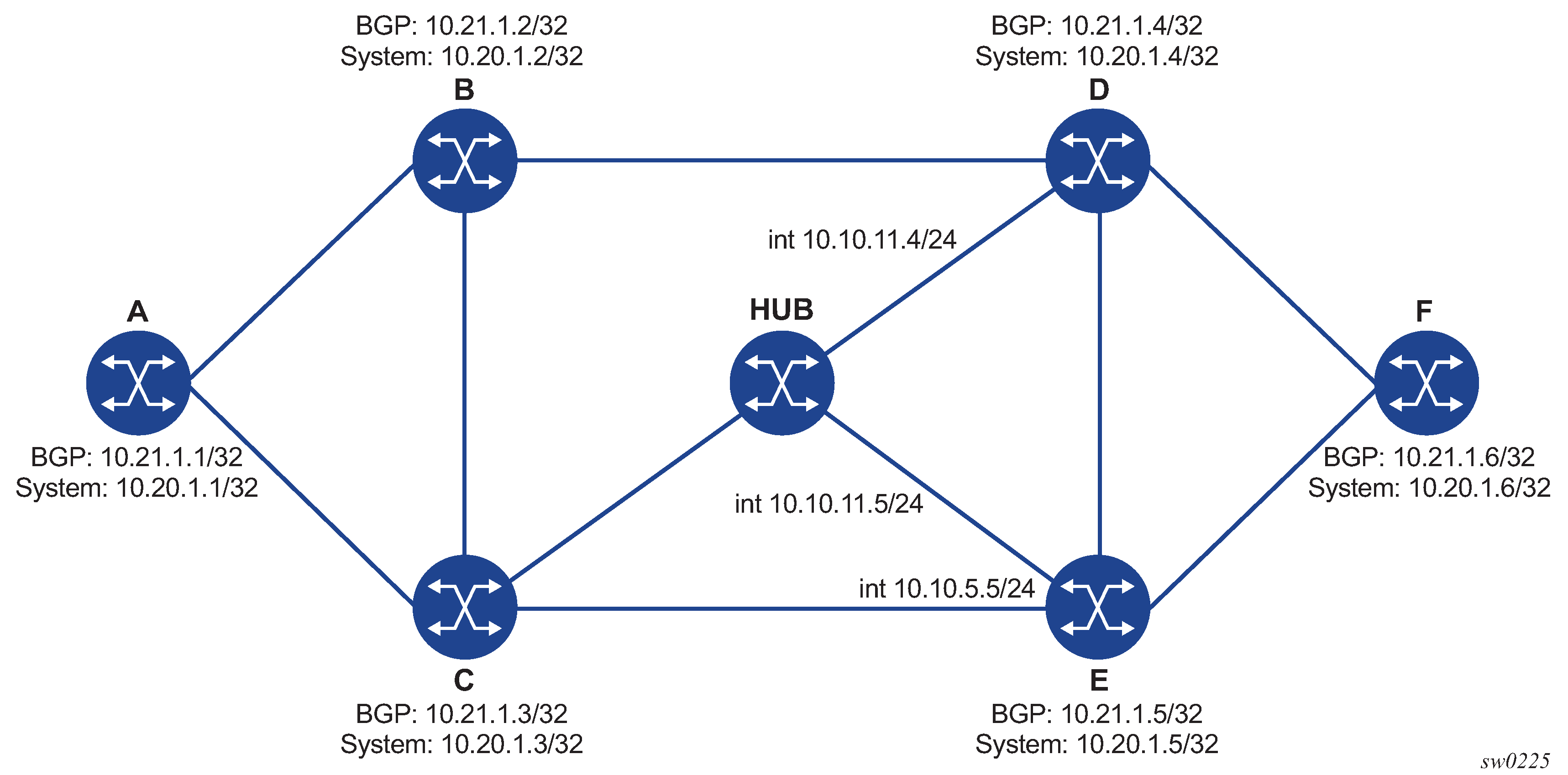
The following are examples of the lsp-trace command output for a hierarchical tunnel consisting of a BGP IPv4 LSP resolved over an SR IS-IS IPv4 tunnel, SR-OSPF IPv4 tunnel, or SR-TE IPv4 LSP.
BGP over SR-OSPF
*A:Dut-A# oam lsp-trace bgp-label prefix 11.21.1.6/32 detail downstream-map-
tlv ddmap path-destination 127.1.1.
lsp-trace to 11.21.1.6/32: 0 hops min, 0 hops max, 168 byte packets
1  10.20.1.3  rtt=2.31ms rc=8(DSRtrMatchLabel) rsc=2
     DS 1: ipaddr=10.10.5.5 ifaddr=10.10.5.5 iftype=ipv4Numbered MRU=1496
           label[1]=27506 protocol=5(OSPF)
           label[2]=262137 protocol=2(BGP)
     DS 2: ipaddr=10.10.11.4 ifaddr=10.10.11.4 iftype=ipv4Numbered MRU=1496
           label[1]=27406 protocol=5(OSPF)
           label[2]=262137 protocol=2(BGP)
     DS 3: ipaddr=10.10.11.5 ifaddr=10.10.11.5 iftype=ipv4Numbered MRU=1496
           label[1]=27506 protocol=5(OSPF)
           label[2]=262137 protocol=2(BGP)
2   10.20.1.4  rtt=4.91ms rc=8(DSRtrMatchLabel) rsc=2
     DS 1: ipaddr=10.10.9.6 ifaddr=10.10.9.6 iftype=ipv4Numbered MRU=1492
           label[1]=27606 protocol=5(OSPF)
           label[2]=262137 protocol=2(BGP)
3  10.20.1.6  rtt=4.73ms rc=3(EgressRtr) rsc=2
3  10.20.1.6  rtt=5.44ms rc=3(EgressRtr) rsc=1
*A:Dut-A#
BGP over SR-TE (OSPF)
*A:Dut-A# oam lsp-trace bgp-label prefix 11.21.1.6/32 detail downstream-map-
tlv ddmap path-destination 127.1.1.1
lsp-trace to 11.21.1.6/32: 0 hops min, 0 hops max, 236 byte packets
1  10.20.1.2  rtt=2.13ms rc=3(EgressRtr) rsc=4
1  10.20.1.2  rtt=1.79ms rc=8(DSRtrMatchLabel) rsc=3
     DS 1: ipaddr=10.10.4.4 ifaddr=10.10.4.4 iftype=ipv4Numbered MRU=1492
           label[1]=3 protocol=5(OSPF)
           label[2]=262104 protocol=5(OSPF)
           label[3]=262139 protocol=2(BGP)
2  10.20.1.4  rtt=3.24ms rc=3(EgressRtr) rsc=3
2  10.20.1.4  rtt=4.46ms rc=8(DSRtrMatchLabel) rsc=2
     DS 1: ipaddr=10.10.9.6 ifaddr=10.10.9.6 iftype=ipv4Numbered MRU=1492
           label[1]=3 protocol=5(OSPF)
           label[2]=262139 protocol=2(BGP)
3  10.20.1.6  rtt=6.24ms rc=3(EgressRtr) rsc=2
3  10.20.1.6  rtt=6.18ms rc=3(EgressRtr) rsc=1
*A:Dut-A#
BGP over SR IS-IS
A:Dut-A# oam lsp-trace bgp-label prefix 11.21.1.6/32 detail downstream-map-
tlv ddmap path-destination 127.1.1.1
lsp-trace to 11.21.1.6/32: 0 hops min, 0 hops max, 168 byte packets
1  10.20.1.3  rtt=3.33ms rc=8(DSRtrMatchLabel) rsc=2
    DS 1:  ipaddr=10.10.5.5 ifaddr=10.10.5.5 iftype=ipv4Numbered MRU=1496
           label[1]=28506 protocol=6(ISIS)
           label[2]=262139 protocol=2(BGP)
     DS 2: ipaddr=10.10.11.4 ifaddr=10.10.11.4 iftype=ipv4Numbered MRU=1496
           label[1]=28406 protocol=6(ISIS)
           label[2]=262139 protocol=2(BGP)
     DS 3: ipaddr=10.10.11.5 ifaddr=10.10.11.5 iftype=ipv4Numbered MRU=1496
           label[1]=28506 protocol=6(ISIS)
           label[2]=262139 protocol=2(BGP)
2  10.20.1.4  rtt=5.12ms rc=8(DSRtrMatchLabel) rsc=2
     DS 1: ipaddr=10.10.9.6 ifaddr=10.10.9.6 iftype=ipv4Numbered MRU=1492
           label[1]=28606 protocol=6(ISIS)
           label[2]=262139 protocol=2(BGP)
3  10.20.1.6  rtt=8.41ms rc=3(EgressRtr) rsc=2
3  10.20.1.6  rtt=6.93ms rc=3(EgressRtr) rsc=1
BGP over SR-TE (IS-IS)
*A:Dut-A# oam lsp-trace bgp-label prefix 11.21.1.6/32 detail downstream-map-
tlv ddmap path-destination 127.1.1.1
lsp-trace to 11.21.1.6/32: 0 hops min, 0 hops max, 248 byte packets
1  10.20.1.2  rtt=2.60ms rc=3(EgressRtr) rsc=4
1  10.20.1.2  rtt=2.29ms rc=8(DSRtrMatchLabel) rsc=3
     DS 1: ipaddr=10.10.4.4 ifaddr=10.10.4.4 iftype=ipv4Numbered MRU=1492
           label[1]=3 protocol=6(ISIS)
           label[2]=262094 protocol=6(ISIS)
           label[3]=262139 protocol=2(BGP)
2  10.20.1.4  rtt=4.04ms rc=3(EgressRtr) rsc=3
2  10.20.1.4  rtt=4.38ms rc=8(DSRtrMatchLabel) rsc=2
     DS 1: ipaddr=10.10.9.6 ifaddr=10.10.9.6 iftype=ipv4Numbered MRU=1492
           label[1]=3 protocol=6(ISIS)
           label[2]=262139 protocol=2(BGP)
3  10.20.1.6  rtt=6.64ms rc=3(EgressRtr) rsc=2
3  10.20.1.6  rtt=5.94ms rc=3(EgressRtr) rsc=1
The following figure shows the topology with the addition of an eBGP peering between nodes B and C, the BGP IPv4 LSP spans the AS boundary and resolves to an SR IS-IS tunnel or an SR-TE LSP within each AS.
BGP over SR IS-IS in inter-AS option C
*A:Dut-A# oam lsp-trace bgp-label prefix 11.20.1.6/32 src-ip-
address 11.20.1.1 detail downstream-map-tlv ddmap path-destination 127.1.1.1
lsp-trace to 11.20.1.6/32: 0 hops min, 0 hops max, 168 byte packets
1  10.20.1.2  rtt=2.69ms rc=3(EgressRtr) rsc=2
1  10.20.1.2  rtt=3.15ms rc=8(DSRtrMatchLabel) rsc=1
     DS 1: ipaddr=10.10.3.3 ifaddr=10.10.3.3 iftype=ipv4Numbered MRU=0
           label[1]=262127 protocol=2(BGP)
2  10.20.1.3  rtt=5.26ms rc=15(LabelSwitchedWithFecChange) rsc=1
     DS 1: ipaddr=10.10.5.5 ifaddr=10.10.5.5 iftype=ipv4Numbered MRU=1496
           label[1]=26506 protocol=6(ISIS)
           label[2]=262139 protocol=2(BGP)
           fecchange[1]=PUSH fectype=SR Ipv4 Prefix prefix=10.20.1.6 remotepeer=10.1
0.5.5
3  10.20.1.5  rtt=7.08ms rc=8(DSRtrMatchLabel) rsc=2
     DS 1: ipaddr=10.10.10.6 ifaddr=10.10.10.6 iftype=ipv4Numbered MRU=1496
           label[1]=26606 protocol=6(ISIS)
       label[2]=262139 protocol=2(BGP)
4  10.20.1.6  rtt=9.41ms rc=3(EgressRtr) rsc=2
4  10.20.1.6  rtt=9.53ms rc=3(EgressRtr) rsc=1
BGP over SR-TE (IS-IS) in inter-AS option C
*A:Dut-A# oam lsp-trace bgp-label prefix 11.20.1.6/32 src-ip-
address 11.20.1.1 detail downstream-map-tlv ddmap path-destination 127.1.1.1
lsp-trace to 11.20.1.6/32: 0 hops min, 0 hops max, 168 byte packets
1  10.20.1.2  rtt=2.77ms rc=3(EgressRtr) rsc=2
1  10.20.1.2  rtt=2.92ms rc=8(DSRtrMatchLabel) rsc=1
     DS 1: ipaddr=10.10.3.3 ifaddr=10.10.3.3 iftype=ipv4Numbered MRU=0
           label[1]=262127 protocol=2(BGP)
2  10.20.1.3  rtt=4.82ms rc=15(LabelSwitchedWithFecChange) rsc=1
     DS 1: ipaddr=10.10.5.5 ifaddr=10.10.5.5 iftype=ipv4Numbered MRU=1496
           label[1]=26505 protocol=6(ISIS)
           label[2]=26506 protocol=6(ISIS)
           label[3]=262139 protocol=2(BGP)
           fecchange[1]=PUSH fectype=SR Ipv4 Prefix prefix=10.20.1.6
remotepeer=0.0.0.0 (Unknown)
           fecchange[2]=PUSH fectype=SR Ipv4 Prefix prefix=10.20.1.5
remotepeer=10.10.5.5
3  10.20.1.5  rtt=7.10ms rc=3(EgressRtr) rsc=3
3  10.20.1.5  rtt=7.45ms rc=8(DSRtrMatchLabel) rsc=2
     DS 1: ipaddr=10.10.10.6 ifaddr=10.10.10.6 iftype=ipv4Numbered MRU=1496
           label[1]=26606 protocol=6(ISIS)
           label[2]=262139 protocol=2(BGP)
4  10.20.1.6  rtt=9.23ms  c=3(EgressRtr) rsc=2
4  10.20.1.6  rtt=9.46ms rc=3(EgressRtr) rsc=1
*A:Dut-A
Operation on an SR-ISIS IPv4 tunnel, IPv6 tunnel, or SR-OSPF IPv4 tunnel resolved over IGP IPv4 shortcuts using RSVP-TE LSPs
When IGP shortcut is enabled in an IS-IS or an OSPF instance and the family SRv4 or SRv6 is set to resolve over RSVP-TE LSPs, a hierarchical tunnel is created whereby an SR-ISIS IPv4 tunnel, an SR-ISIS IPv6 tunnel, or an SR-OSPF tunnel resolves over the IGP IPv4 shortcuts using RSVP-TE LSPs.
The following example outputs are of the lsp-trace command for a hierarchical tunnel consisting of an SR‑ISIS IPv4 tunnel and an SR-OSPF IPv4 tunnel, resolving over an IGP IPv4 shortcut using a RSVP-TE LSP.
The topology, as shown in Example topology for SR-ISIS over RSVP-TE and SR-OSPF over RSVP-TE, is used for the following SR-ISIS over RSVP-TE and SR-OSPF over RSVP-TE example outputs.
SR-ISIS over RSVP-TE
*A:Dut-F# oam lsp-trace sr-isis prefix 10.20.1.1/32 detail path-destination 127.1.1.1 igp-instance 1
lsp-trace to 10.20.1.1/32: 0 hops min, 0 hops max, 180 byte packets
1  10.20.1.4  rtt=5.05ms rc=8(DSRtrMatchLabel) rsc=2
     DS 1: ipaddr=10.10.4.2 ifaddr=10.10.4.2 iftype=ipv4Numbered MRU=1500
           label[1]=262121 protocol=4(RSVP-TE)
           label[2]=28101 protocol=6(ISIS)
2  10.20.1.2  rtt=5.56ms rc=8(DSRtrMatchLabel) rsc=2
     DS 1: ipaddr=10.10.1.1 ifaddr=10.10.1.1 iftype=ipv4Numbered MRU=1500
           label[1]=262124 protocol=4(RSVP-TE)
           label[2]=28101 protocol=6(ISIS)
3  10.20.1.1  rtt=7.30ms rc=3(EgressRtr) rsc=2
3  10.20.1.1  rtt=5.40ms rc=3(EgressRtr) rsc=1
*A:Dut-F#
SR-OSPF over RSVP-TE
*A:Dut-F# oam lsp-trace sr-ospf prefix 10.20.1.1/32 detail path-destination 127.1.1.1 igp-instance 2
lsp-trace to 10.20.1.1/32: 0 hops min, 0 hops max, 180 byte packets
1  10.20.1.4  rtt=3.24ms rc=8(DSRtrMatchLabel) rsc=2
     DS 1: ipaddr=10.10.4.2 ifaddr=10.10.4.2 iftype=ipv4Numbered MRU=1500
           label[1]=262125 protocol=4(RSVP-TE)
           label[2]=27101 protocol=5(OSPF)
2  10.20.1.2  rtt=5.77ms rc=8(DSRtrMatchLabel) rsc=2
     DS 1: ipaddr=10.10.1.1 ifaddr=10.10.1.1 iftype=ipv4Numbered MRU=1500
           label[1]=262124 protocol=4(RSVP-TE)
           label[2]=27101 protocol=5(OSPF)
3  10.20.1.1  rtt=7.19ms rc=3(EgressRtr) rsc=2
3  10.20.1.1  rtt=8.41ms rc=3(EgressRtr) rsc=1
Operation on an LDP IPv4 FEC resolved over IGP IPv4 shortcuts using SR-TE LSPs
When IGP shortcut is enabled in an IS-IS or an OSPF instance and the family IPv4 is set to resolve over SR-TE LSPs, a hierarchical tunnel is created whereby an LDP IPv4 FEC resolves over the IGP IPv4 shortcuts using SR-TE LSPs.
The following example outputs show the lsp-trace command for a hierarchical tunnel consisting of a LDP IPv4 FEC resolving over a IGP IPv4 shortcut using a SR-TE LSP.
The topology, as shown in Example topology for LDP over SR-TE (ISIS) and LDP over SR-TE (OSPF), is used for the following LDP over SR-TE (ISIS) and LDP over SR-TE (OSPF) example outputs.
LDP over SR-TE (ISIS)
*A:Dut-F# oam lsp-trace prefix 10.20.1.1/32 detail path-destination 127.1.1.1
lsp-trace to 10.20.1.1/32: 0 hops min, 0 hops max, 184 byte packets
1  10.20.1.4  rtt=2.33ms rc=8(DSRtrMatchLabel) rsc=3
     DS 1: ipaddr=10.10.4.2 ifaddr=10.10.4.2 iftype=ipv4Numbered MRU=1492
           label[1]=28202 protocol=6(ISIS)
           label[2]=28201 protocol=6(ISIS)
           label[3]=262138 protocol=3(LDP)
2  10.20.1.2  rtt=6.39m rc=3(EgressRtr) rsc=3
2  10.20.1.2  rtt=7.29ms rc=8(DSRtrMatchLabel) rsc=2
     DS 1: ipaddr=10.10.1.1 ifaddr=10.10.1.1 iftype=ipv4Numbered MRU=1492
           label[1]=28101 protocol=6(ISIS)
           label[2]=262138 protocol=3(LDP)
3  10.20.1.1  rtt=8.34m rc=3(EgressRtr) rsc=2
3  10.20.1.1  rtt=9.37ms rc=3(EgressRtr) rsc=1

*A:Dut-F# oam lsp-ping prefix 10.20.1.1/32 detail
LSP-PING 10.20.1.1/32: 80 bytes MPLS payload
Seq=1, send from intf int_to_D, reply from 10.20.1.1
     udp-data-len=32 ttl=255 rtt=8.21ms rc=3 (EgressRtr)
---- LSP 10.20.1.1/32 PING Statistics ----
1 packets sent, 1 packets received, 0.00% packet loss
round-trip mi = 8.21ms, avg = 8.21ms, max = 8.21ms, stddev = 0.000ms
===============================================================================
LDP Bindings (IPv4 LSR ID 10.20.1.6)
             (IPv6 LSR ID fc00::a14:106)
===============================================================================
Label Status:
        U - Label In Use, N - Label Not In Use, W - Label Withdrawn
        WP - Label Withdraw Pending, BU - Alternate For Fast Re-Route
        e - Label ELC
FEC Flags:
        LF - Lower FEC, UF - Upper FEC, M - Community Mismatch, BA - ASBR Backup FEC
===============================================================================
LDP IPv4 Prefix Bindings
===============================================================================
Prefix                                      IngLbl                    EgrLbl
Peer                                        EgrIntf/LspId
EgrNextHop
-------------------------------------------------------------------------------
10.20.1.1/32                                  --                      262138
10.20.1.1:0                                 LspId 655467
10.20.1.1

10.20.1.1/32                                262070U                   262040
10.20.1.3:0                                   --
  --

10.20.1.1/32                                262070U                   --
10.20.1.4:0                                   --
  --

10.20.1.1/32                                262070U                   262091
10.20.1.5:0                                   --
  --

10.20.1.1/32                                  --                      262138
fc00::a14:101[0]                              --
  --

10.20.1.1/32                                262070U                   262040
fc00::a14:103[0]                              --
  --

10.20.1.1/32                                262070U                   262091
fc00::a14:105[0]                              --
  --

-------------------------------------------------------------------------------
No. of IPv4 Prefix Bindings: 7
===============================================================================
LDP over SR-TE (OSPF)
*A:Dut-F# oam lsp-trace prefix 10.20.1.1/32 detail path-destination 127.1.1.1
lsp-trace to 10.20.1.1/32: 0 hops min, 0 hops max, 184 byte packets
1  10.20.1.4  rtt=2.73ms rc=8(DSRtrMatchLabel) rsc=3
     DS 1: ipaddr=10.10.4.2 ifaddr=10.10.4.2 iftype=ipv4Numbered MRU=1492
           label[1]=27202 protocol=5(OSPF)
           label[2]=27201 protocol=5(OSPF)
           label[3]=262143 protocol=3(LDP)
2  10.20.1.2  rtt=6.77ms rc=3(EgressRtr) rsc=3
2  10.20.1.2  rtt=6.75ms rc=8(DSRtrMatchLabel) rsc=2
     DS 1: ipaddr=10.10.1.1 ifaddr=10.10.1.1 iftype=ipv4Numbered MRU=1492
           label[1]=27101 protocol=5(OSPF)
           label[2]=262143 protocol=3(LDP)
3  10.20.1.1  rtt=7.10ms rc=3(EgressRtr) rsc=2
3  10.20.1.1  rtt=7.53ms rc=3(EgressRtr) rsc=1

*A:Dut-F# oam lsp-ping prefix 10.20.1.1/32 detail
LSP-PING 10.20.1.1/32: 80 bytes MPLS payload
Seq=1, send from intf int_to_D, reply from 10.20.1.1
       udp-data-len=32 ttl=255 rtt=8.09ms rc=3 (EgressRtr)

---- LSP 10.20.1.1/32 PING Statistics ----
1 packets sent, 1 packets received, 0.00% packet loss
round-trip min = 8.09ms, avg = 8.09ms, max = 8.09ms, stddev = 0.000ms

===============================================================================
LDP Bindings (IPv4 LSR ID 10.20.1.6)
             (IPv6 LSR ID fc00::a14:106)
===============================================================================
Label Status:
        U - Label In Use, N - Label Not In Use, W - Label Withdrawn
        WP - Label Withdraw Pending, BU - Alternate For Fast Re-Route
        e - Label ELC
FEC Flags:
        LF - Lower FEC, UF - Upper FEC, M - Community Mismatch, BA - ASBR Backup FEC
===============================================================================
LDP IPv4 Prefix Bindings
===============================================================================
Prefix                                      IngLbl                    EgrLbl
Peer                                        EgrIntf/LspId
EgrNextHop
-------------------------------------------------------------------------------
10.20.1.1/32                                  --                      262143
10.20.1.1:0                                 LspId 655467
10.20.1.1

10.20.1.1/32                                262089U                   262135
10.20.1.3:0                                   --
  --

10.20.1.1/32                                262089U                     --
10.20.1.4:0                                   --
  --

10.20.1.1/32                                262089U                   262129
10.20.1.5:0                                   --
  --

10.20.1.1/32                                  --                      262143
fc00::a14:101[0]                              --
  --

10.20.1.1/32                                262089U                   262135
fc00::a14:103[0]                              --
  --

10.20.1.1/32                                262089U                   262129
fc00::a14:105[0]                              --
  --

-------------------------------------------------------------------------------
No. of IPv4 Prefix Bindings: 7
===============================================================================
Tunneling of ICMP reply packets over MPLS LSP
This feature enables the tunneling of ICMP reply packets over MPLS LSP at an LSR node as defined in RFC 3032. At an LSR node, including an ABR, ASBR, or datapath Router Reflector (RR) node, the user enables the ICMP tunneling feature globally on the system using the config>router>icmp-tunneling command.
This feature supports tunneling ICMP replies to a UDP traceroute message. It does not support tunneling replies to an icmp ping message. The LSR part of this feature consists of crafting the reply ICMP packet of type=11- 'time exceeded', with a source address set to a local address of the LSR node, and appending the IP header and leading payload octets of the original datagram. The system skips the lookup of the source address of the sender of the label TTL expiry packet, which becomes the destination address of the ICMP reply packet. Instead, CPM injects the ICMP reply packet in the forward direction of the MPLS LSP the label TTL expiry packet was received from. The TTL of pushed labels should be set to 255.
The source address of the ICMP reply packet is determined as follows:
-
The LSR uses the address of the outgoing interface for the MPLS LSP.
Note: With LDP LSP or BGP LSP, multiple ECMP next-hops can exist in which case the first outgoing interface is selected. -
If the interface does not have an address of the same family (IPv4 or IPv6) as the ICMP packet, the system address of the same family is selected. If one is not configured, the packet is dropped.
When the packet is received by the egress LER, it performs a regular user packet lookup in the datapath in the GRT context for BGP shortcut, 6PE, and BGP labeled route prefixes, or in VPRN context for VPRN and 6VPE prefixes. It then forwards it to the destination, which is the sender of the original packet which TTL expired at the LSR.
If the egress LER does not have a route to the destination of the ICMP packet, it drops the packets.
The 7705 SAR Gen 2 router implementation supports appending to the ICMP reply of type Time Exceeded the MPLS label stack object defined in RFC 4950. It does not include it in the ICMP reply type of Destination unreachable.
The MPLS Label Stack object allows an LSR to include label stack information including label value, EXP, and TTL field values, from the encapsulation header of the packet that expired at the LSR node. The ICMP message continues to include the IP header and leading payload octets of the original datagram.
To include the MPLS Label Stack object, the SR OS implementation adds support of RFC 4884, Extended ICMP to Support Multipart Messages, which defines extensions for a multipart ICMPv4/v6 message of type Time Exceeded. Section 5 of RFC 4884 defines backward compatibility of the new ICMP message with extension header with prior standard and proprietary extension headers.
To guarantee interoperability with third-party implementations deployed in customer networks, the router implementation is able to parse in the receive side all possible encapsulations formats as defined in Section 5 of RFC 4884. Specifically:
The MPLS Label Stack object allows an LSR to include label stack information including label value, EXP, and TTL field values, from the encapsulation header of the packet that expired at the LSR node. The ICMP message continues to include the IP header and leading payload octets of the original datagram.
-
If the length attribute is zero, it is treated as a compliant message and the router implementation processes the original datagram field of size equal to 128 bytes and with no extension header.
-
If the length attribute is not included, it is treated as a non-compliant message and the router implementation processes the original datagram field of size equal to 128 bytes and also look for a valid extension header following the 128 byte original datagram field. If the extension is valid, it is processed accordingly, if not it is assumed the remainder of the packet is still part of the original datagram field and process it accordingly.
Note: The router implementation only validates the ICMP extension version number and not the checksum field in the extension header. The checksum of the main time exceeded message is also not validated as per prior implementation. -
An ICMP reply message is dropped if it includes more than one MPLS label object. In general, when a packet is dropped because of an error in the packet header or structure, the traceroute times out and an error message is not displayed.
-
When processing the received ICMP reply packet, an unsupported extension header is skipped.
In the transmit side, when the MPLS Label Stack object is added as an extension to the ICMP reply message, it is appended to the message immediately following the "original datagram" field taken from the payload of the received traceroute packet. The size of the appended "original datagram" field contains exactly 128 octets. If the original datagram did not contain 128 octets, the "original datagram" field is zero padded to 128 octets.
For example output of the traceroute OAM tool when the ICMP tunneling feature is enabled see Traceroute with ICMP tunneling in common applications.
QoS handling of tunneled ICMP reply packets
When the ICMP reply packet is generated in CPM, its FC is set by default to NC1 with the corresponding default ToS byte value of 0xC0. The DSCP value can be changed by configuring a different value for an ICMP application under the config>router>sgt-qos icmp context.
When the packet is forwarded to the outgoing interface, the packet is queued in the egress network queue corresponding to its CPM assigned FC and profile parameter values. The marking of the packet's EXP is dictated by the {FC, profile}-to-EXP mapping in the network QoS policy configured on the outgoing network interface. The ToS byte, and DSCP value for that matter, assigned by CPM are not modified by the IOM.
Summary of UDP traceroute behavior with and without ICMP tunneling
At a high level, the major difference in the behavior of the UDP traceroute when ICMP tunneling is enabled at an LSR node is that the LSR node tunnels the ICMP reply packet toward the egress of the LSP without looking up the traceroute sender's address. When ICMP tunneling is disabled, the LSR looks it up and replies if the sender is reachable. However there are additional differences in the two behaviors and they are summarized in the following information:
icmp-tunneling disabled/IPv4 LSP/IPv4 traceroute
Ingress LER, egress LER, and LSR attempt to reply to the UDP traceroute of both IPv4 and VPN-IPv4 routes.
For VPN-IPv4 routes, the LSR attempts to reply but it may not find a route and in such a case the sender node times out. In addition, the ingress and egress ASBR nodes in VPRN inter-AS option B do not respond as in current implementation and the sender times out.
icmp-tunneling disabled/IPv4 LSP/IPv6 traceroute
Ingress LER and egress LER reply to traceroute of both IPv6 and VPN-IPv6 routes. LSR does not reply.
icmp-tunneling enabled/IPv4 LSP/IPv4 traceroute
Ingress LER and egress LER reply directly to the UDP traceroute of both IPv4 and VPN-IPv4 routes. LSR tunnels the reply to the endpoint of the LSP to be forwarded from there to the source of the traceroute.
For VPN-IPv4 routes, the ingress and egress ASBR nodes in VPRN inter-AS option B also tunnel the reply to the endpoint of the LSP; and therefore, there is no timeout at the sender node like in the case when icmp-tunneling is disabled.
icmp-tunneling enabled/IPv4 LSP/IPv6 traceroute
Ingress LER and egress LER reply directly to the UDP traceroute of both IPv6 and VPN-IPv6 routes. LSR tunnels the reply to the endpoint of the LSP to be forwarded from there to the source of the traceroute.
For VPN-IPv6 routes, the ingress and egress ASBR nodes in VPRN inter-AS option B also tunnel the reply to the endpoint of the LSP like in the case when icmp-tunneling is disabled.
In the presence of ECMP, CPM generated UDP traceroute packets are not sprayed over multiple ECMP next-hops. The first outgoing interface is selected. In addition, a LSR ICMP reply to a UDP traceroute is also forwarded over the first outgoing interface regardless if ICMP tunneling is enabled or not. When ICMP tunneling is enabled, it means the packet is tunneled over the first downstream interface for the LSP when multiple next-hops exist (LDP FEC or BGP labeled route). In all cases, the ICMP reply packet uses the outgoing interface address as the source address of the reply packet.
SDP diagnostics
The router SDP diagnostics are SDP ping and SDP MTU path discovery.
SDP ping
SDP ping performs in-band unidirectional or round-trip connectivity tests on SDPs. The SDP ping OAM packets are sent in-band, in the tunnel encapsulation, so they follow the same path as traffic within the service. The SDP ping response can be received out-of-band in the control plane, or in-band using the data plane for a round-trip test.
For a unidirectional test, SDP ping tests:
egress SDP ID encapsulation
ability to reach the far-end IP address of the SDP ID within the SDP encapsulation
path MTU to the far-end IP address over the SDP ID
forwarding class mapping between the near-end SDP ID encapsulation and the far-end tunnel termination
For a round-trip test, SDP ping uses a local egress SDP ID and an expected remote SDP ID. Because SDPs are unidirectional tunnels, the remote SDP ID must be specified and must exist as a configured SDP ID on the far-end router SDP round trip testing is an extension of SDP connectivity testing with the additional ability to test:
remote SDP ID encapsulation
potential service round trip time
round trip path MTU
round trip forwarding class mapping
SDP MTU path discovery
In a large network, network devices can support a variety of packet sizes that are transmitted across its interfaces. This capability is referred to as the Maximum Transmission Unit (MTU) of network interfaces. It is important to understand the MTU of the entire path end-to-end when provisioning services, especially for virtual leased line (VLL) services where the service must support the ability to transmit the largest customer packet.
The Path MTU discovery tool provides a powerful tool that enables service provider to get the exact MTU supported by the network's physical links between the service ingress and service termination points (accurate to one byte).
Service diagnostics
- service ping
- IGMP snooping
- various VPLS MAC diagnostic tools
- various VLL diagnostic tools
IGMP snooping diagnostics
IP PM
SR OS supports Two-Way Active Measurement Protocol (TWAMP) and Two-Way Active Measurement Protocol Light (TWAMP Light) and Simple Two-Way Active Measurement Protocol (STAMP).
TWAMP
TWAMP provides a standards-based method for measuring the IP performance (packet loss, delay, and jitter) between two devices. TWAMP leverages the methodology and architecture of One-Way Active Measurement Protocol (OWAMP) to define a way to measure two-way or round-trip metrics.
There are four logical entities in TWAMP: the Control-Client, the Session-Sender, the server, and the Session-Reflector. The Control-Client and Session-Sender are typically implemented in one physical device (the ‟client”) and the server and Session-Reflector in a second physical device (the ‟server”). The router acts as the ‟server”.
The Control-Client and server establish a TCP connection and exchange TWAMP-Control messages over this connection. When a server accepts the TCP control session from the Control-Client, it responds with a server greeting message. This greeting includes the various modes supported by the server. The modes are in the form of a bit mask. Each bit in the mask represents a functionality supported on the server. When the Control-Client wants to start testing, the client communicates the test parameters to the server, requesting any of the modes that the server supports. If the server agrees to conduct the described tests, the test begins as soon as the Control-Client sends a Start-Sessions or Start-N-Session message. As part of a test, the Session-Sender sends a stream of UDP-based TWAMP test packets to the Session-Reflector, and the Session-Reflector responds to each received packet with a UDP-response TWAMP test packet. When the Session-Sender receives the response packets from the Session-Reflector, the information is used to calculate two-way delay, packet loss, and packet delay variation between the two devices. The exchange of TWAMP test PDUs is referred to as a TWAMP-Test.
The TWAMP test PDU does not achieve symmetrical packet size in both directions unless the frame is padded with a minimum of 27 bytes. The Session-Sender is responsible for applying the required padding. After the frame is appropriately padded, the Session-Reflector reduces the padding by the number of bytes needed to provide symmetry.
Server mode support includes:
-
individual session control (Mode Bit 4: Value 16)
-
reflected octets (Mode Bit 5: Value 32)
-
symmetrical size test packet (Mode Bit 6: Value 64)
TWAMP Light and STAMP
This section provides information about TWAMP Light and STAMP.
Overview
SR OS is an early adopter of IP PM under the OAM Performance Monitoring (OAM-PM) architecture. The test PDU format was derived from TWAMP Light based on RFC 5357, section "Informational Appendix I". As TWAMP Light gained community support and large deployment, it became the defacto standard for IP performance measurement. Following community acceptance, the IETF published RFC 7862, Simple Two-way Active Measurement Protocol (STAMP).
In link measurement, the Session-Sender uses STAMP-formatted packets because of the requirement to support the TLV structure described in RFC 8972, STAMP Optional Extensions.
In link measurement on LAG, the Session-Sender uses TWAMP Light-formatted packets in accordance with the reassignment of TWAMP Light test PDU fields that were previously Must Be Zero (MBZ).
configure oam-pm session ip twamp-light session-sender-typeTWAMP Light was introduced as part of RFC 5357, A Two-Way Active Measurement Protocol (TWAMP), Appendix I (Informational). The RFC appendix defined a single-ended test without the requirement to use the TCP control channel over which the Control-Client and server negotiate test parameters. Using this approach, configuration on both entities, the Session-Sender and the Session-Reflector, replaces the control channel and provides the application-specific handling information required to launch and reflect test packets. In other words, TWAMP Light uses the TWAMP test packet for gathering IP performance information, but eliminates the need for the TWAMP TCP control channel.
This informational work formed the baseline for standardization of TWAMP Light by RFC 8762, Simple Two-Way Active Measurement Protocol (STAMP). The STAMP standard defined by RFC 8762 is backward compatible with RFC 5357 Appendix I. As the STAMP work in the IETF continues to evolve, the backward compatibility has remained largely unchanged between the RCF 5357 appendix and the base STAMP RFC 8762 . Even with the publication of RFC 8972, Simple Two-Way Active Measurement Protocol Optional Extension reasonable interoperability has been maintained.
Unless specifically required, the Session-Reflector should be configured with type stamp to provide the highest level of interoperability for different Session-Senders.
Use the following command to configure the test packet processing behavior for the Session-Reflector.
configure router twamp-light reflector type
The Session-Reflector uses the twamp-light and stamp options to determine its processing behavior for the test packet received from the Session-Sender. The default processing behavior is that twamp-light performs no TLV processing, treating any non-base TWAMP Light packet as padding. If the required behavior for the Session-Reflector is to parse and process STAMP TLVs, the stamp option must be used. Using the stamp configuration, the Session-Reflector can accommodate both TWAMP Light and STAMP Session-Senders, processing the packet based on the TLV rules as defined in RFC 8972. Any Session-Sender that is transmitting TWAMP Light test PDU-formatted test packets with additional padding must use an all-zero pattern to avoid ambiguity on the Session-Reflector.
The following describes PDU padding and the identification of STAMP TLVs.
- TWAMP Light
The TWAMP Light test packet request and response sizes are asymmetrical by default. The Session-Sender packet and the Session-Reflector packets are different sizes by default. To allow for symmetrical packets on the wire and packet size manipulation, the Session-Sender can configure the pad-size octets command to increase the size of the packet. These octets are added directly to the base packet.
- STAMP
The STAMP test packet request and response sizes are symmetrical by default. RFC 8762 defines a structured packet that ensures this behavior. To allow for packet size manipulation, the STAMP Optional Extensions RFC 8972 defines a PAD TLV. This TLV is added after the base packet. STAMP padding uses the pad-tlv-size octets command to increase the size of the packet.
Session-Reflector
The Session-Reflector receives and processes TWAMP Light test packets.
Use the following context to configure the Session-Reflector functions for base router reflection.
configure router twamp-lightUse the following context to configure Session-Reflector functions for per VPRN reflection.
configure service vprn twamp-light The TWAMP Light Session-Reflector function is configured per context and must be activated before reflection can occur; the function is not enabled by default for any context. The Session-Reflector requires the user to define the TWAMP Light UDP listening port that identifies the TWAMP Light protocol. All the prefixes that the reflector accepts as valid sources for a TWAMP Light request must also be configured. If the source IP address in the TWAMP Light test packet arriving on the Session-Reflector does not match the configured prefixes, the packet is dropped. Multiple prefix entries may be configured per context on the Session-Reflector. Configured prefixes can be modified without shutting down the reflector function.
If an In-Service Software Upgrade (ISSU) function is invoked when the udp-port udp-port-number is outside the allowable range and the TWAMP Light Session-Reflector is in a no shutdown state, the ISSU operation cannot proceed. The user must, at a minimum, disable the TWAMP Light Session-Reflector to allow the ISSU to proceed; however, the TWAMP Light Session-Reflector is not allowed to be enable until a value in the allowable range is configured. A non-ISSU upgrade can proceed regardless of the state (enabled or disabled) of the TWAMP Light Session-Reflector. The configuration can load, but the TWAMP Light Session-Reflector remains inactive following the reload when the allowable range is not configured.
When the udp-port udp-port-number for a TWAMP Light Session-Reflector is modified, all tests using the services of that reflector must update the dest-udp-port udp-port-number configuration parameter to match the new reflector listening port.
The TWAMP-Light Session-Reflector is stateful and supports unidirectional synthetic loss detection. An inactivity timeout under the config>oam-test>twamp>twamp-light command hierarchy defines the amount of time the TWAMP-Light Session-Reflector maintains individual test session in the absence of the arrival of test packets for that session.
The TWAMP-Light Session-Reflector responds using the timestamp format that is indicated in the test packet from the Session-Sender. The Error Estimate Field is a two-byte field that includes the Z bit to indicate the format of the needed timestamp. The TWAMP-Light Session-Reflector checks this field and replies using the same format for timestamp two (T2) and timestamp three (T3). The TWAMP-Light Session-Reflector does not interrogate or change the other bits in the Error Estimate field. Except for the processing of Z-bit, the received Error Estimate is reflected back to the Session-Sender.
Configurations that require an IPv6 UDP checksum of zero are increasing. In some cases, hardware timestamping functions that occur in the UDP header occur after the computation of the UDP checksum. Typically, packets that arrive with an IPv6 UDP checksum of zero are discarded. However, an optional configuration command allow-ipv6-udp-checksum-zero allows those packets to be accepted and processed for the configured UDP port of the TWAMP Light Session-Reflector.
Multiple tests sessions between peers are allowed. These test sessions are unique entities and may have different properties. Each test generates test packets specific to their configuration. The TWAMP Light Session-Reflector includes the SSID defined by RFC 8972 as a fifth element augmenting the source IP, destination IP, source UDP port, and destination UDP port when maintaining the test state.
As TWAMP Light evolved, the TWAMP Light Session-Reflector required a method to determine processing of the arriving Session-Sender packets. The default processing behavior is type twamp-light. This treats all additional bytes beyond the base TWAMP Light packet as padding. The type stamp attempts to locate STAMP TLVs defined by RFC 8972 for processing.
See OAM Performance Monitoring for more information about the integration of TWAMP Light in related applications.
Bidirectional Forwarding Detection
Bidirectional Forwarding Detection (BFD) is an efficient, short-duration detection of failures in the path between two systems. If a system stops receiving BFD messages for a long enough period (based on configuration), it is assumed that a failure along the path has occurred and the associated protocol or service is notified of the failure.
BFD can provide a mechanism used for failure detection over any media, at any protocol layer, with a wide range of detection times and overhead, to avoid a proliferation of different methods.
SR OS supports asynchronous and on-demand modes of BFD in which BFD messages are sent to test the path between systems.
If multiple protocols are running between the same two BFD endpoints, only a single BFD session is established, and all associated protocols share the single BFD session.
As well as the typical asynchronous mode, there is also an echo function defined within RFC 5880, Bidirectional Forwarding Detection, that allows either of the two systems to send a sequence of BFD echo packets to the other system, which loops them back within that system’s forwarding plane. If a number of these echo packets are lost, the BFD session is declared down.
BFD control packet
The base BFD specification does not specify the encapsulation type to be used for sending BFD control packets. Instead, use the appropriate encapsulation type for the medium and network. The encapsulation for BFD over IPv4 and IPv6 networks is specified in RFC 5881, Bidirectional Forwarding Detection (BFD) for IPv4 and IPv6 (Single Hop), and RFC 5883, Bidirectional Forwarding Detection (BFD) for Multihop Paths, BFD for IPv4 and IPv6. This specification requires that BFD control packets be sent over UDP with a destination port number of 3784 (single hop) or 4784 (multihop paths) and the source port number must be within the range 49152 to 65535.
Also, the TTL of all transmitted BFD packets must have an IP TTL of 255. All BFD packets received must have an IP TTL of 255 if authentication is not enabled. If authentication is enabled, the IP TTL should be 255, but can still be processed if it is not (assuming the packet passes the enabled authentication mechanism).
If multiple BFD sessions exist between two nodes, the BFD discriminator is used to de-multiplex the BFD control packet to the appropriate BFD session.
Control packet format
The BFD control packet has two sections: a mandatory section and an optional authentication section.
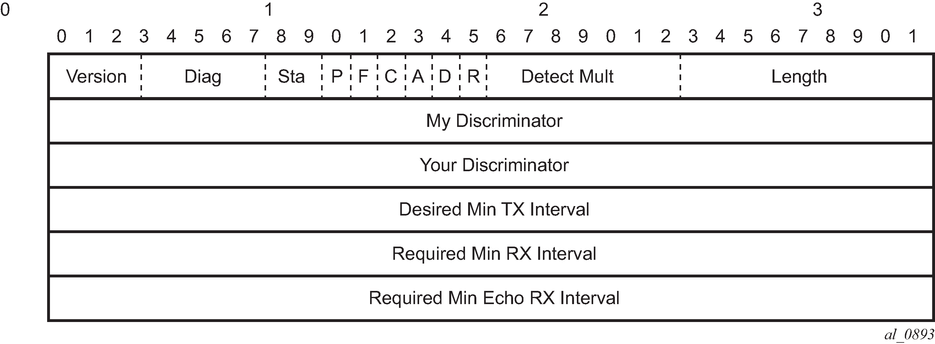
| Field | Description |
|---|---|
Vers |
The version number of the protocol. The initial protocol version is 0. |
Diag |
A diagnostic code specifying the local system’s reason for the last transition of the session from Up to some other state. Possible values are: 0-No diagnostic 1-Control detection time expired 2-Echo function failed 3-Neighbor signaled session down 4-Forwarding plane reset 5-Path down 6-Concatenated path down 7-Administratively down |
D Bit |
The demand mode bit. (Not supported) |
P Bit |
The poll bit. If set, the transmitting system is requesting verification of connectivity, or of a parameter change. |
F Bit |
The final bit. If set, the transmitting system is responding to a received BFD control packet that had the poll (P) bit set. |
Rsvd |
Reserved bits. These bits must be zero on transmit and ignored on receipt. |
Length |
Length of the BFD control packet, in bytes. |
My Discriminator |
A unique, non-zero discriminator value generated by the transmitting system, used to demultiplex multiple BFD sessions between the same pair of systems. |
Your Discriminator |
The discriminator received from the corresponding remote system. This field reflects back the received value of my discriminator, or is zero if that value is unknown. |
Desired Min TX Interval |
This is the minimum interval, in microseconds, that the local system would like to use when transmitting BFD control packets. |
Required Min RX Interval |
This is the minimum interval, in microseconds, between received BFD control packets that this system is capable of supporting. |
Required Min Echo RX Interval |
This is the minimum interval, in microseconds, between received BFD echo packets that this system is capable of supporting. If this value is zero, the transmitting system does not support the receipt of BFD echo packets. |
Echo support
Echo support for BFD calls for the support of the echo function within BFD. By supporting BFD echo, the router loops back received BFD echo messages to the original sender based on the destination IP address in the packet.
The echo function is useful when the local router does not have sufficient CPU power to handle a periodic polling rate at a high frequency. Therefore, it relies on the echo sender to send a high rate of BFD echo messages through the receiver node, which is only processed by the receiver’s forwarding path. This allows the echo sender to send BFD echo packets at any rate.
SR OS does not support the sending of echo requests, only the response to echo requests.
Traceroute with ICMP tunneling in common applications
This section provides example output of the traceroute OAM tool when the ICMP tunneling feature is enabled in a few common applications.
The ICMP tunneling feature is described in Tunneling of ICMP reply packets over MPLS LSP and provides supports for appending to the ICMP reply of type Time Exceeded the MPLS label stack object defined in RFC 4950. The new MPLS Label Stack object allows an LSR to include label stack information including label value, EXP, and TTL field values, from the encapsulation header of the packet that expired at the LSR node.
BGP-LDP stitching and ASBR/ABR/datapath RR for BGP IPv4 labeled route
ASBR1     ASBR2
            -------- D ------- E --------
           |                             |
           |                             |
A -------- C                             F -------- B
DSLAM1    PE1                           PE2       DSLAM2
           |                             |
           |                             |
            -------- G ------- H --------
                   ASBR3     ASBR4

# lsp-trace ldp-bgp stitching
*A:Dut-A# oam lsp-trace prefix 10.20.1.6/32 detail downstream-map-
tlv ddmap
lsp-trace to 10.20.1.6/32: 0 hops min, 0 hops max, 108 byte packets
1  10.20.1.1  rtt=2.89ms rc=15(LabelSwitchedWithFecChange) rsc=1
     DS 1: ipaddr=10.10.1.2 ifaddr=10.10.1.2 iftype=ipv4Numbered MRU=1496
           label[1]=262143 protocol=3(LDP)
           label[2]=262139 protocol=2(BGP)
           fecchange[1]=POP  fectype=LDP IPv4 prefix=10.20.1.6 remotepeer=0.0.0.0 (Unknown)
fecchange[2]=PUSH fectype=BGP IPv4 prefix=10.20.1.6 remotepeer=10.20.1.2
           fecchange[3]=PUSH fectype=LDP IPv4 prefix=10.20.1.2 remotepeer=10.10.1.2
2  10.20.1.2  rtt=5.19ms rc=3(EgressRtr) rsc=2
2  10.20.1.2  rtt=5.66ms rc=8(DSRtrMatchLabel) rsc=1
     DS 1: ipaddr=10.10.4.4 ifaddr=10.10.4.4 iftype=ipv4Numbered MRU=0
           label[1]=262138 protocol=2(BGP)
3  10.20.1.4  rtt=6.53ms rc=15(LabelSwitchedWithFecChange) rsc=1
     DS 1: ipaddr=10.10.6.5 ifaddr=10.10.6.5 iftype=ipv4Numbered MRU=1496
           label[1]=262143 protocol=3(LDP)
           label[2]=262138 protocol=2(BGP)
           fecchange[1]=PUSH fectype=LDP IPv4 prefix=10.20.1.5 remotepeer=10.10.6.5
4  10.20.1.5  rtt=8.51ms rc=3(EgressRtr) rsc=2
4  10.20.1.5  rtt=8.45ms rc=15(LabelSwitchedWithFecChange) rsc=1
     DS 1: ipaddr=10.10.10.6 ifaddr=10.10.10.6 iftype=ipv4Numbered MRU=1496
           label[1]=262143 protocol=3(LDP)
           fecchange[1]=POP  fectype=BGP IPv4 prefix=10.20.1.6 remotepeer=0.0.0.0
(Unknown)
           fecchange[2]=PUSH fectype=LDP IPv4 prefix=10.20.1.6 remotepeer=10.10.10.6
5  10.20.1.6  rtt=11.2ms rc=3(EgressRtr) rsc=1
*A:Dut-A# configure router ldp-
shortcut (to add ldp label on first hop but overall behavior is similar)

# 12.0R4 default behavior (we have routes back to the source)
*A:Dut-A# traceroute 10.20.1.6 detail wait 100
traceroute to 10.20.1.6, 30 hops max, 40 byte packets
  1   1  10.10.2.1  (10.10.2.1)  3.47 ms
  1   2  10.10.2.1  (10.10.2.1)  3.65 ms
  1   3  10.10.2.1  (10.10.2.1)  3.46 ms
  2   1  10.10.1.2  (10.10.1.2)  5.46 ms
  2   2  10.10.1.2  (10.10.1.2)  5.83 ms
  2   3  10.10.1.2  (10.10.1.2)  5.20 ms
  3   1  10.10.4.4  (10.10.4.4)  8.55 ms
  3   2  10.10.4.4  (10.10.4.4)  7.45 ms
  3   3  10.10.4.4  (10.10.4.4)  7.29 ms
  4   1  10.10.6.5  (10.10.6.5)  9.67 ms
  4   2  10.10.6.5  (10.10.6.5)  10.1 ms
  4   3  10.10.6.5  (10.10.6.5)  10.9 ms
  5   1  10.20.1.6  (10.20.1.6)  11.5 ms
  5   2  10.20.1.6  (10.20.1.6)  11.1 ms
  5   3  10.20.1.6  (10.20.1.6)  11.4 ms


# Enable ICMP tunneling on PE and ASBR nodes.
*A:Dut-D# # configure router ttl-propagate label-route-local all *A:Dut-
C,D,E,F# configure router icmp-tunneling

*A:Dut-C# traceroute 10.20.1.6 detail wait 100
traceroute to 10.20.1.6, 30 hops max, 40 byte packets
  1   1  10.10.1.1  (10.10.1.1)  11.8 ms
         returned MPLS Label Stack Object
             entry  1:  MPLS Label =  262138, Exp = 7, TTL =   1, S = 1
  1   2  10.10.1.1  (10.10.1.1)  12.5 ms
         returned MPLS Label Stack Object
             entry  1:  MPLS Label =  262138, Exp = 7, TTL =   1, S = 1
  1   3  10.10.1.1  (10.10.1.1)  12.9 ms
         returned MPLS Label Stack Object
             entry  1:  MPLS Label =  262138, Exp = 7, TTL =   1, S = 1
  2   1  10.10.4.2  (10.10.4.2)  13.0 ms
         returned MPLS Label Stack Object
             entry  1:  MPLS Label =  262143, Exp = 7, TTL =   1, S = 0
             entry  2:  MPLS Label =  262139, Exp = 7, TTL =   1, S = 1
  2   2  10.10.4.2  (10.10.4.2)  13.0 ms
         returned MPLS Label Stack Object
             entry  1:  MPLS Label =  262143, Exp = 7, TTL =   1, S = 0
             entry  2:  MPLS Label =  262139, Exp = 7, TTL =   1, S = 1
  2   3  10.10.4.2  (10.10.4.2)  12.8 ms
         returned MPLS Label Stack Object
             entry  1:  MPLS Label =  262143, Exp = 7, TTL =   1, S = 0
             entry  2:  MPLS Label =  262139, Exp = 7, TTL =   1, S = 1
  3   1  10.10.6.4  (10.10.6.4)  10.1 ms
         returned MPLS Label Stack Object
             entry  1:  MPLS Label =  262138, Exp = 7, TTL =   1, S = 1
  3   2  10.10.6.4  (10.10.6.4)  11.1 ms
         returned MPLS Label Stack Object
             entry  1:  MPLS Label =  262138, Exp = 7, TTL =   1, S = 1
  3   3  10.10.6.4  (10.10.6.4)  9.70 ms
         returned MPLS Label Stack Object
             entry  1:  MPLS Label =  262138, Exp = 7, TTL =   1, S = 1
  4   1  10.10.10.5  (10.10.10.5)  12.5 ms
         returned MPLS Label Stack Object
             entry  1:  MPLS Label =  262143, Exp = 7, TTL = 255, S = 0
             entry  2:  MPLS Label =  262138, Exp = 7, TTL =   1, S = 1
  4   2  10.10.10.5  (10.10.10.5)  11.9 ms
         returned MPLS Label Stack Object
             entry  1:  MPLS Label =  262143, Exp = 7, TTL = 255, S = 0
             entry  2:  MPLS Label =  262138, Exp = 7, TTL =   1, S = 1
  4   3  10.10.10.5  (10.10.10.5)  11.8 ms
         returned MPLS Label Stack Object
             entry  1:  MPLS Label =  262143, Exp = 7, TTL = 255, S = 0
             entry  2:  MPLS Label =  262138, Exp = 7, TTL =   1, S = 1
  5   1  10.20.1.6  (10.20.1.6)  12.2 ms
  5   2  10.20.1.6  (10.20.1.6)  12.5 ms
  5   3  10.20.1.6  (10.20.1.6)  13.2 ms


# With lsr-label-route all on all LSRs (only needed on Dut-E) *A:Dut-
E# configure router ttl-propagate lsr-label-route all

*A:Dut-
A# traceroute 10.20.1.6 detail wait 100 traceroute to 10.20.1.6, 30 hops max, 40 byt
e packets
  1   1  10.10.1.1  (10.10.1.1)  12.4 ms
         returned MPLS Label Stack Object
             entry  1:  MPLS Label =  262138, Exp = 7, TTL =   1, S = 1
  1   2  10.10.1.1  (10.10.1.1)  11.9 ms
         returned MPLS Label Stack Object
             entry  1:  MPLS Label =  262138, Exp = 7, TTL =   1, S = 1
  1   3  10.10.1.1  (10.10.1.1)  12.7 ms
         returned MPLS Label Stack Object
             entry  1:  MPLS Label =  262138, Exp = 7, TTL =   1, S = 1
  2   1  10.10.4.2  (10.10.4.2)  11.6 ms
         returned MPLS Label Stack Object
             entry  1:  MPLS Label =  262143, Exp = 7, TTL =   1, S = 0
             entry  2:  MPLS Label =  262139, Exp = 7, TTL =   1, S = 1
  2   2  10.10.4.2  (10.10.4.2)  13.5 ms
         returned MPLS Label Stack Object
             entry  1:  MPLS Label =  262143, Exp = 7, TTL =   1, S = 0
             entry  2:  MPLS Label =  262139, Exp = 7, TTL =   1, S = 1
  2   3  10.10.4.2  (10.10.4.2)  11.9 ms
         returned MPLS Label Stack Object
             entry  1:  MPLS Label =  262143, Exp = 7, TTL =   1, S = 0
             entry  2:  MPLS Label =  262139, Exp = 7, TTL =   1, S = 1
  3   1  10.10.6.4  (10.10.6.4)  9.21 ms
         returned MPLS Label Stack Object
             entry  1:  MPLS Label =  262138, Exp = 7, TTL =   1, S = 1
  3   2  10.10.6.4  (10.10.6.4)  9.58 ms
         returned MPLS Label Stack Object
             entry  1:  MPLS Label =  262138, Exp = 7, TTL =   1, S = 1
  3   3  10.10.6.4  (10.10.6.4)  9.38 ms
         returned MPLS Label Stack Object
             entry  1:  MPLS Label =  262138, Exp = 7, TTL =   1, S = 1
  4   1  10.10.10.5  (10.10.10.5)  12.2 ms
         returned MPLS Label Stack Object
             entry  1:  MPLS Label =  262143, Exp = 7, TTL =   1, S = 0
             entry  2:  MPLS Label =  262138, Exp = 7, TTL =   1, S = 1
  4   2  10.10.10.5  (10.10.10.5)  11.5 ms
         returned MPLS Label Stack Object
             entry  1:  MPLS Label =  262143, Exp = 7, TTL =   1, S = 0
             entry  2:  MPLS Label =  262138, Exp = 7, TTL =   1, S = 1
  4   3  10.10.10.5  (10.10.10.5)  11.5 ms
         returned MPLS Label Stack Object
             entry  1:  MPLS Label =  262143, Exp = 7, TTL =   1, S = 0
             entry  2:  MPLS Label =  262138, Exp = 7, TTL =   1, S = 1
  5   1  10.20.1.6  (10.20.1.6)  11.9 ms
  5   2  10.20.1.6  (10.20.1.6)  12.2 ms
  5   3  10.20.1.6  (10.20.1.6)  13.7 ms
VPRN inter-AS option B
      ASBR1     ASBR2
            -------- D ------- E --------
           |                             |
           |                             |
A -------- C                             F -------- B
CE1       PE1                           PE2        CE2
           |                             |
           |                             |
            -------- G ------- H --------
                   ASBR3     ASBR4

# 12.0R4 default behavior (vc-only)
*A:Dut-A# traceroute 3.3.3.4 source 3.3.4.2 wait 100 no-dns
detail traceroute to 3.3.3.4 from 3.3.4.2, 30 hops max, 40 byte packets
  1   1  3.3.4.1  1.97 ms
  1   2  3.3.4.1  1.74 ms
  1   3  3.3.4.1  1.71 ms
  2   1  *
  2   2  *
  2   3  *
  3   1  *
  3   2  *
  3   3  *
  4   1  3.3.3.6  6.76 ms
  4   2  3.3.3.6  7.37 ms
  4   3  3.3.3.6  8.36 ms
  5   1  3.3.3.4  11.1 ms
  5   2  3.3.3.4  9.46 ms
  5   3  3.3.3.4  8.28 ms


# Configure icmp-tunneling on C, D, E and F

*A:Dut-A# traceroute 3.3.3.4 source 3.3.4.2 wait 100 no-dns
detail traceroute to 3.3.3.4 from 3.3.4.2, 30 hops max, 40 byte packets
  1   1  3.3.4.1  1.95 ms
  1   2  3.3.4.1  1.85 ms
  1   3  3.3.4.1  1.62 ms
  2   1  10.0.7.3  6.76 ms
         returned MPLS Label Stack Object
             entry  1:  MPLS Label =  262143, Exp = 0, TTL = 255, S = 0
             entry  2:  MPLS Label =  262140, Exp = 0, TTL =   1, S = 1
  2   2  10.0.7.3  6.92 ms
         returned MPLS Label Stack Object
             entry  1:  MPLS Label =  262143, Exp = 0, TTL = 255, S = 0
             entry  2:  MPLS Label =  262140, Exp = 0, TTL =   1, S = 1
  2   3  10.0.7.3  7.58 ms
         returned MPLS Label Stack Object
             entry  1:  MPLS Label =  262143, Exp = 0, TTL = 255, S = 0
             entry  2:  MPLS Label =  262140, Exp = 0, TTL =   1, S = 1
  3   1  10.0.5.4  6.92 ms
         returned MPLS Label Stack Object
             entry  1:  MPLS Label =  262140, Exp = 0, TTL =   1, S = 1
  3   2  10.0.5.4  7.03 ms
         returned MPLS Label Stack Object
             entry  1:  MPLS Label =  262140, Exp = 0, TTL =   1, S = 1
  3   3  10.0.5.4  8.66 ms
         returned MPLS Label Stack Object
             entry  1:  MPLS Label =  262140, Exp = 0, TTL =   1, S = 1
  4   1  3.3.3.6  6.67 ms
  4   2  3.3.3.6  6.75 ms
  4   3  3.3.3.6  6.96 ms
  5   1  3.3.3.4  8.32 ms
  5   2  3.3.3.4  11.6 ms
  5   3  3.3.3.4  8.45 ms


# With ttl-propagate vprn-transit none on PE1 *A:Dut-C# configure router ttl-
propagate vprn-transit none *A:Dut-B# traceroute 3.3.3.4 source 3.3.4.2 wait 100 no-
dns detail traceroute to 3.3.3.4 from 3.3.4.2, 30 hops max, 40 byte packets
  1   1  3.3.4.1  1.76 ms
  1   2  3.3.4.1  1.75 ms
  1   3  3.3.4.1  1.76 ms
  2   1  3.3.3.6  6.50 ms
  2   2  3.3.3.6  6.70 ms
  2   3  3.3.3.6  6.36 ms
  3   1  3.3.3.4  8.34 ms
  3   2  3.3.3.4  7.64 ms
  3   3  3.3.3.4  8.73 ms


# With ttl-propagate vprn-transit all on PE1 *A:Dut-C# configure router ttl-
propagate vprn-transit all *A:Dut-B# traceroute 3.3.3.4 source 3.3.4.2 wait 100 no-
dns detail traceroute to 3.3.3.4 from 3.3.4.2, 30 hops max, 40 byte packets
  1   1  3.3.4.1  1.97 ms
  1   2  3.3.4.1  1.77 ms
  1   3  3.3.4.1  2.37 ms
  2   1  10.0.7.3  9.27 ms
         returned MPLS Label Stack Object
             entry  1:  MPLS Label =  262143, Exp = 0, TTL =   1, S = 0
             entry  2:  MPLS Label =  262140, Exp = 0, TTL =   1, S = 1
  2   2  10.0.7.3  6.39 ms
         returned MPLS Label Stack Object
             entry  1:  MPLS Label =  262143, Exp = 0, TTL =   1, S = 0
             entry  2:  MPLS Label =  262140, Exp = 0, TTL =   1, S = 1
  2   3  10.0.7.3  6.19 ms
         returned MPLS Label Stack Object
             entry  1:  MPLS Label =  262143, Exp = 0, TTL =   1, S = 0
             entry  2:  MPLS Label =  262140, Exp = 0, TTL =   1, S = 1
  3   1  10.0.5.4  6.80 ms
         returned MPLS Label Stack Object
             entry  1:  MPLS Label =  262140, Exp = 0, TTL =   1, S = 1
  3   2  10.0.5.4  6.71 ms
         returned MPLS Label Stack Object
             entry  1:  MPLS Label =  262140, Exp = 0, TTL =   1, S = 1
  3   3  10.0.5.4  6.58 ms
         returned MPLS Label Stack Object
             entry  1:  MPLS Label =  262140, Exp = 0, TTL =   1, S = 1
  4   1  3.3.3.6  6.47 ms
  4   2  3.3.3.6  6.75 ms
  4   3  3.3.3.6  9.06 ms
  5   1  3.3.3.4  7.99 ms
  5   2  3.3.3.4  9.31 ms
  5   3  3.3.3.4  8.13 ms
VPRN inter-AS option C and ASBR/ABR/datapath RR for BGP IPv4 labeled route
      ASBR1     ASBR2
            -------- D ------- E --------
           |                             |
           |                             |
A -------- C                             F -------- B
CE1       PE1                           PE2        CE2
           |                             |
           |                             |
            -------- G ------- H --------
                   ASBR3     ASBR4

# 12.0R4 default behavior

*A:Dut-B# traceroute 16.1.1.1 source 26.1.1.2 detail no-dns
wait 100 traceroute to 16.1.1.1 from 26.1.1.2, 30 hops max, 40 byte packets
  1   1  26.1.1.1  1.90 ms
  1   2  26.1.1.1  1.81 ms
  1   3  26.1.1.1  2.01 ms
  2   1  16.1.1.1  6.11 ms
  2   2  16.1.1.1  8.35 ms
  2   3  16.1.1.1  5.33 ms

*A:Dut-C# traceroute router 600 26.1.1.2 source 16.1.1.1 detail no-dns
wait 100 traceroute to 26.1.1.2 from 16.1.1.1, 30 hops max, 40 byte packets
  1   1  26.1.1.1  5.03 ms
  1   2  26.1.1.1  4.60 ms
  1   3  26.1.1.1  4.60 ms
  2   1  26.1.1.2  6.54 ms
  2   2  26.1.1.2  5.99 ms
  2   3  26.1.1.2  5.74 ms


# With ttl-propagate vprn-transit all and icmp-tunneling

*A:Dut-B# traceroute 16.1.1.1 source 26.1.1.2 detail no-dns
wait 100 traceroute to 16.1.1.1 from 26.1.1.2, 30 hops max, 40 byte packets
  1   1  26.1.1.1  2.05 ms
  1   2  26.1.1.1  1.87 ms
  1   3  26.1.1.1  1.85 ms
  2   1  10.10.4.4  8.42 ms
         returned MPLS Label Stack Object
             entry  1:  MPLS Label =  262143, Exp = 0, TTL =   1, S = 0
             entry  2:  MPLS Label =  262137, Exp = 0, TTL =   1, S = 0
             entry  3:  MPLS Label =  262142, Exp = 0, TTL =   1, S = 1
  2   2  10.10.4.4  5.85 ms
         returned MPLS Label Stack Object
             entry  1:  MPLS Label =  262143, Exp = 0, TTL =   1, S = 0
             entry  2:  MPLS Label =  262137, Exp = 0, TTL =   1, S = 0
             entry  3:  MPLS Label =  262142, Exp = 0, TTL =   1, S = 1
  2   3  10.10.4.4  5.75 ms
         returned MPLS Label Stack Object
             entry  1:  MPLS Label =  262143, Exp = 0, TTL =   1, S = 0
             entry  2:  MPLS Label =  262137, Exp = 0, TTL =   1, S = 0
             entry  3:  MPLS Label =  262142, Exp = 0, TTL =   1, S = 1
  3   1  10.10.1.2  5.54 ms
         returned MPLS Label Stack Object
             entry  1:  MPLS Label =  262137, Exp = 0, TTL =   1, S = 0
             entry  2:  MPLS Label =  262142, Exp = 0, TTL =   2, S = 1
  3   2  10.10.1.2  7.89 ms
         returned MPLS Label Stack Object
             entry  1:  MPLS Label =  262137, Exp = 0, TTL =   1, S = 0
             entry  2:  MPLS Label =  262142, Exp = 0, TTL =   2, S = 1
  3   3  10.10.1.2  5.56 ms
         returned MPLS Label Stack Object
             entry  1:  MPLS Label =  262137, Exp = 0, TTL =   1, S = 0
             entry  2:  MPLS Label =  262142, Exp = 0, TTL =   2, S = 1
  4   1  16.1.1.1  9.50 ms
  4   2  16.1.1.1  5.91 ms
  4   3  16.1.1.1  5.85 ms


# With ttl-propagate vprn-local all
*A:Dut-C# traceroute router 600 26.1.1.2 source 16.1.1.1 detail no-dns
wait 100 traceroute to 26.1.1.2 from 16.1.1.1, 30 hops max, 40 byte packets
  1   1  10.10.4.2  4.78 ms
         returned MPLS Label Stack Object
             entry  1:  MPLS Label =  262143, Exp = 7, TTL =   1, S = 0
             entry  2:  MPLS Label =  262136, Exp = 7, TTL =   1, S = 0
             entry  3:  MPLS Label =  262142, Exp = 7, TTL =   1, S = 1
  1   2  10.10.4.2  4.56 ms
         returned MPLS Label Stack Object
             entry  1:  MPLS Label =  262143, Exp = 7, TTL =   1, S = 0
             entry  2:  MPLS Label =  262136, Exp = 7, TTL =   1, S = 0
             entry  3:  MPLS Label =  262142, Exp = 7, TTL =   1, S = 1
  1   3  10.10.4.2  4.59 ms
         returned MPLS Label Stack Object
             entry  1:  MPLS Label =  262143, Exp = 7, TTL =   1, S = 0
             entry  2:  MPLS Label =  262136, Exp = 7, TTL =   1, S = 0
             entry  3:  MPLS Label =  262142, Exp = 7, TTL =   1, S = 1
  2   1  10.10.6.4  4.55 ms
         returned MPLS Label Stack Object
             entry  1:  MPLS Label =  262138, Exp = 7, TTL =   1, S = 0
             entry  2:  MPLS Label =  262142, Exp = 7, TTL =   2, S = 1
  2   2  10.10.6.4  4.47 ms
         returned MPLS Label Stack Object
             entry  1:  MPLS Label =  262138, Exp = 7, TTL =   1, S = 0
             entry  2:  MPLS Label =  262142, Exp = 7, TTL =   2, S = 1
  2   3  10.10.6.4  4.20 ms
         returned MPLS Label Stack Object
             entry  1:  MPLS Label =  262138, Exp = 7, TTL =   1, S = 0
             entry  2:  MPLS Label =  262142, Exp = 7, TTL =   2, S = 1
  3   1  26.1.1.1  4.62 ms
  3   2  26.1.1.1  4.41 ms
  3   3  26.1.1.1  4.64 ms
  4   1  26.1.1.2  5.74 ms
  4   2  26.1.1.2  6.22 ms
  4   3  26.1.1.2  5.77 ms