IP router configuration
This chapter provides information about commands required to configure basic router command options.
Configuring IP router command options
To provision services on a Nokia router, logical IP routing interfaces must be configured to associate attributes such as an IP address, port, or the system with the IP interface.
A special type of IP interface is the system interface. A system interface must have an IP address with a 32-bit subnet mask. The system interface is used as the router identifier by higher-level protocols such as OSPF and BGP, unless overwritten by an explicit router ID.
The following router features can be configured:
Interfaces
Nokia routers use different types of interfaces for various functions. Interfaces must be configured with information such as the interface type (network and system) and address. A port is not associated with a system interface. An interface can be associated with the system (loopback address).
Network interface
A network interface (a logical IP routing interface) can be configured on one of the following entities:
physical or logical port
Network domains
To determine which network ports (and, therefore, which network complexes) are eligible to transport traffic of individual SDPs, network-domain is provided. Network-domain information is then used for the sap-ingress queue allocation algorithm applied to VPLS SAPs. This algorithm is optimized in so that no sap-ingress queues are allocated if the specified port does not belong to the network-domain used in the specified VPLS. Also, sap-ingress queues are not allocated toward network ports (regardless of the network-domain membership) if the specified VPLS does not contain any SDPs.
SAP-ingress queue allocation considers the following:
SHG membership of individual SDPs
network-domain definition under SDP to restrict the topology in which the specified SDP can be set-up
The implementation supports four network-domains within any VPLS.
Network-domain configuration at the SDP level is ignored when the SDP is used for Epipe or Ipipe bindings.
Network-domain configurations are irrelevant for Layer 3 services (Layer 3 VPN and IES services). Network-domain configurations can be defined in the base routing context and associated only with network interfaces in this context. Network domains are not applicable to loopback and system interfaces.
The network-domain information is only used for ingress VPLS sap queue-allocation. It is not considered by routing during SDP setup. Therefore, if the specified SDP is routed through network interfaces that are not part of the configured network domain, the packets are still forwarded, but their QoS and queuing behavior is based on default settings. Also, the packet does not appear in SAP statistics.
There is always one network-domain with the reserved name default. The interfaces always belong to a default network-domain. It is possible to assign a specific interface to different user-defined network-domains. The loopback and system interfaces are also associated with the default network-domain at the creation. However, any attempt to associate those interfaces with any explicitly defined network-domain is blocked at the CLI level because there is no benefit for that association.
Any SDP can be assigned only to one network domain. If none is specified, the system assigns the default network-domain. This means that all SAPs in VPLS have queues reaching all fwd-complexes serving interfaces that belong to the same network-domains as the SDPs.
It is possible to assign or remove network-domain association of the interface/SDP without requiring deletion of the respective object.
System interface
The system interface is associated with the network entity (such as a specific router or switch), not a specific interface. The system interface is also referred to as the loopback address. The system interface is associated during the configuration of the following entities:
the termination point of service tunnels
the hops when configuring MPLS paths and LSPs
the addresses on a target router for BGP and LDP peering
The system interface is used to preserve connectivity (when routing reconvergence is possible) when an interface fails or is removed. The system interface is used as the router identifier, and a system interface must have an IP address with a 32-bit subnet mask.
Unicast reverse path forwarding check
Unicast reverse path forwarding check (uRPF) helps to mitigate problems that are caused by the introduction of malformed or forged (spoofed) IP source addresses into a network by discarding IP packets that lack a verifiable IP source address. For example, a number of common types of denial-of-service (DoS) attacks, including smurf and tribe flood network (TFN), can take advantage of forged or rapidly changing source addresses to allow attackers to thwart efforts to locate or filter the attacks. For Internet service providers (ISPs) that provide public access, uRPF deflects such attacks by forwarding only packets with source addresses that are valid and consistent with the IP routing table. This action protects the network of the ISP, its customer, and the rest of the Internet.
uRPF is supported for both IPv4 and IPv6 on network and access. It is supported on any IP interface, including base router, IES, VPRN, and subscriber group interfaces.
In strict mode, uRPF checks whether the incoming packet has a source address that matches a prefix in the routing table, and whether the interface expects to receive a packet with this source address prefix.
In loose mode, uRPF checks whether the incoming packet has a source address that matches a prefix in the routing table; loose mode does not check whether the interface expects to receive a packet with a specific source address prefix.
Loose mode uRPF check is supported for ECMP, IGP shortcuts, and VPRN MP-BGP routes. Packets coming from a source that matches any ECMP, IGP shortcut, or VPRN MP-BGP route passes the uRPF check even when uRPF is set to strict mode on the incoming interface.
In the case of ECMP, this allows a packet received on an IP interface configured in strict uRPF mode to be forwarded if the source address of the packet matches an ECMP route, even if the IP interface is not a next-hop of the ECMP route or not a member of any ECMP routes. The strict-no-ecmp uRPF mode may be configured on any interface that is known to not be a next-hop of any ECMP route. When a packet is received on this interface, and the source address matches an ECMP route, the packet is dropped by uRPF.
If there is a default route, the following is included in the uRPF check:
A loose mode uRPF check always succeeds.
A strict mode uRPF check only succeeds if the source address matches any route (including the default route) where the next-hop is on the incoming interface for the packet.
Otherwise, the uRPF check fails.
If the source IP address matches a discard/blackhole route, the packet is treated as if it failed the uRPF check.
Configuring link delay
The delay represents the unidirectional link delay from the local router to the remote router (that is, the forward-path latency). The interface delay is a link property and is typically calculated as the combination of speed of light versus fiber length versus fiber composition. Typically, these delay components are not subject to sudden change in a network. If change occurs, it tends to be because of fiber cuts (such as light out) or Layer 1 reroute events.
If delay is configured for all links in the network, the attribute can be used as a feasible metric for SR flex-algo applications.
The static delay represents a forward-path metric, in microseconds, between two routers. It is not possible to configure a delay on a loopback or system interface; the delay IGP extension TLVs (specified in RFC 8570) are not defined for stub links. The delay is encoded in IGP application-specific attributes (for example, for IS-IS, see draft-ietf-isis-te-app-14.txt). The delay can be configured upon other interface links.
The default setting is no delay, which means that IGP (for example, IS-IS) does not add a link delay metric TLV. The lack of this TLV in flex-algo causes the link with the no delay TLV setting to be pruned from the topology.
The following example shows the configuration of link delay.
MD-CLI
[ex:/configure router "Base"]
A:admin@node-2# info
    interface interface-name {
        if-attribute {
            delay {
                static microseconds
            }
        }
    }
classic CLI
A:node-2>config>router# info
#--------------------------------------------------
echo "IP Configuration"
#--------------------------------------------------
        interface "interface-name"
            if-attribute
                delay
                    static microseconds
                exit
            exit
            no shutdown
        exit
The static delay can be configured within the range 1 to 16777214 microseconds.
Router ID
The router ID, a 32-bit number, uniquely identifies the router within an autonomous system (AS) (see Autonomous systems). In protocols such as OSPF, routing information is exchanged between areas—groups of networks that share routing information. It can be set to be the same as the loopback address. The router ID is used by both OSPF and BGP routing protocols in the routing table manager instance.
There are several ways to obtain the router ID. On each router, the router ID can be obtained in the following ways.
-
Define the router ID. Use the following command to define the value that becomes the router ID.
configure router Configure the system interface with an IP address. If the router ID is not manually configured in the configure router context, the system interface acts as the router ID. Use the following command to configure the system interface with an IP address.
configure router interfaceIf neither the system interface nor router ID are implicitly specified, the router ID is inherited from the last four bytes of the MAC address.
The router can be obtained from the protocol level; for example, BGP.
Autonomous systems
Networks can be grouped into areas. An area is a collection of network segments within an AS that have been administratively assigned to the same group. The topology of an area is concealed from the rest of the AS, which results in a significant reduction in routing traffic.
Routing in the AS takes place on two levels, depending on whether the source and destination of a packet reside in the same area (intra-area routing) or different areas (inter-area routing). In intra-area routing, the packet is routed solely on information obtained within the area; no routing information obtained from outside the area can be used. This protects intra-area routing from the injection of bad routing information.
Routers that belong to more than one area are called area border routers. All routers in an AS do not have an identical topological database. An area border router has a separate topological database for each area it is connected to. Two routers, which are not area border routers, belonging to the same area, have identical area topological databases.
ASs share routing information, such as routes to each destination and information about the route or AS path, with other ASs using BGP. Routing tables contain lists of next-hops, reachable addresses, and associated path cost metrics to each router. BGP uses the information and path attributes to compile a network topology.
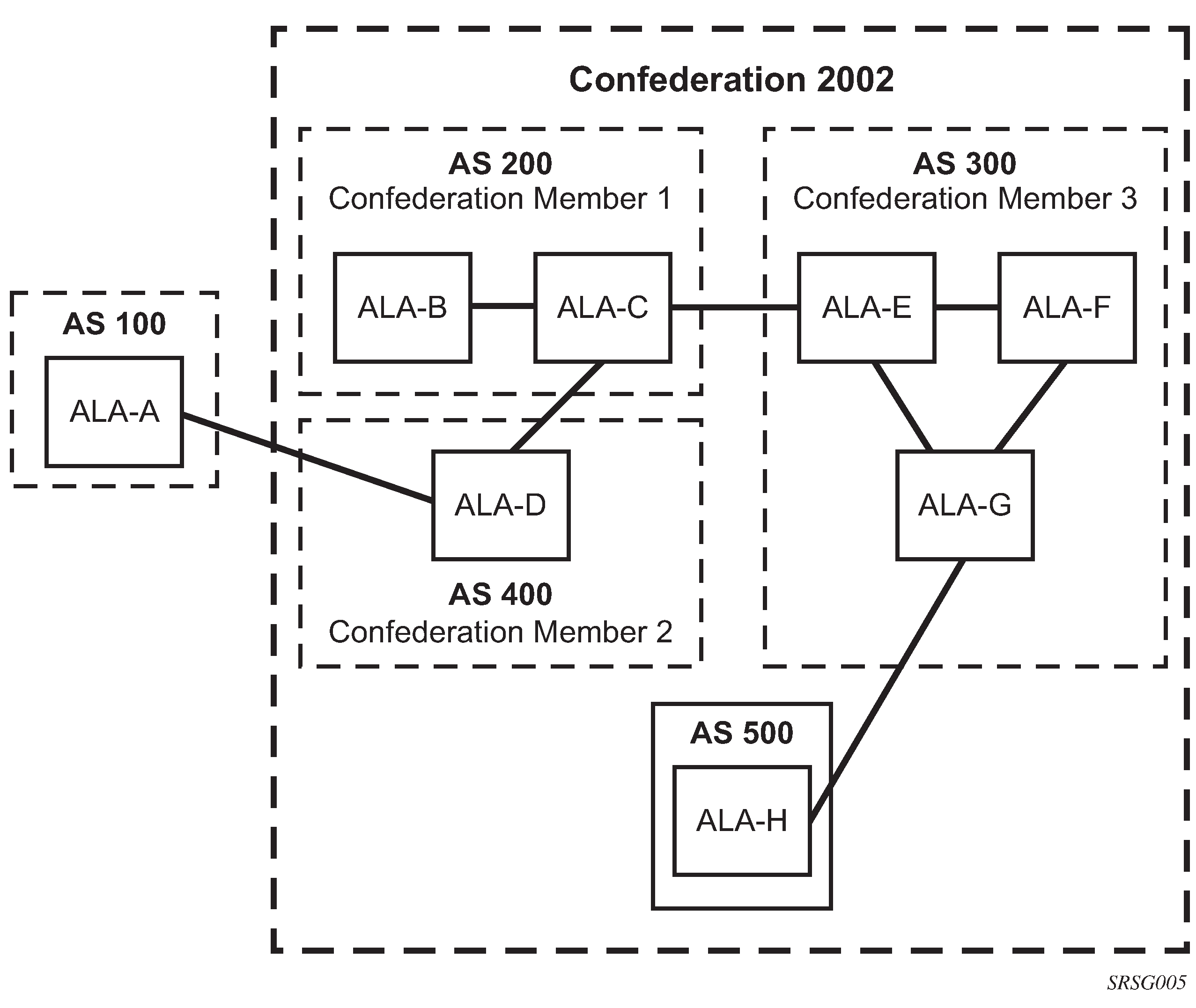
Confederations
Configuring confederations is optional and should be implemented only to reduce the iBGP mesh inside an AS. An AS can be logically divided into smaller groupings called sub-confederations and then assigned a confederation ID (similar to an autonomous system number (ASN)). Each sub-confederation has fully meshed iBGP and connections to other ASs outside of the confederation.
The sub-confederations have eBGP-type peers to other sub-confederations within the confederation. They exchange routing information as if they were using iBGP. Command options such as next hop, metric, and local preference are preserved. The confederation appears and behaves like a single AS.
Confederations have the following characteristics:
A large AS can be sub-divided into sub-confederations.
Routing within each sub-confederation is accomplished via iBGP.
eBGP is used to communicate between sub-confederations.
BGP speakers within a sub-confederation must be fully meshed.
Each sub-confederation (member) of the confederation has a different ASN. The ASNs used are typically in the private AS range of 64512 to 65535.
To migrate from a non-confederation configuration to a confederation configuration requires a major topology change and configuration modifications on each participating router. Setting BGP policies to select an optimal path through a confederation requires other BGP modifications.
There are no default confederations. Router confederations must be explicitly created. The following figure shows an example of a confederation configuration.
Proxy ARP
Proxy ARP is the technique in which a router answers ARP requests intended for another node. The router appears to be present on the same network as the ‟real” node that is the target of the ARP and takes responsibility for routing packets to the ‟real” destination. Proxy ARP can help nodes on a subnet reach remote subnets without configuring routing or a default gateway. Typical routers only support proxy ARP for directly attached networks; the router is targeted to support proxy ARP for all known networks in the routing instance where the virtual interface proxy ARP is configured.
To support DSLAM and other edge-like environments, proxy ARP supports policies that allow the provider to configure prefix lists that determine the target networks and source hosts for which proxy ARP is attempted.
In addition, the proxy ARP implementation supports the ability to respond for other hosts within the local subnet domain. This is needed in environments such as DSL where multiple hosts are in the same subnet but cannot reach each other directly.
Static ARP is used when a Nokia router needs to know about a device on an interface that cannot or does not respond to ARP requests. The configuration can state that if it has a packet with a specific IP address, to send it to the corresponding ARP address. Use proxy ARP so the router responds to ARP requests on behalf of another device.
Exporting an inactive BGP route from a VPRN
Use the following command to provide an IP VPN command option that allows the best BGP route learned by a VPRN to be exported as a VPN-IP route even when that BGP route is inactive because of the presence of a more preferred BGP-VPN route from another PE.
configure service vprn export-inactive-bgpThis ‟best-external” type of route advertisement is useful in active or standby multihoming scenarios because it can ensure that all PEs have knowledge of the backup path provided by the standby PE.
DHCP relay
Because DHCP requests are broadcast packets that normally do not propagate outside of their IP subnet, a DHCP relay agent intercepts such requests and forwards them as unicast messages to a configured DHCP server.
When forwarding a DHCP message, the relay agent sets the GIADDR in the packet to the IP address of its ingress interface. This allows DHCP clients to use a DHCP server on a remote network. From both a scalability and a security point of view, it is recommended that the DHCP relay agent is positioned as close as possible to the client terminals.
DHCP relay is used in a Layer 3 environment, and therefore is only supported in IES services and VPRN services.
When DHCP clients and servers are in different VPRN routing instances of which one is the Base routing instance, route leaking (GRT-leaking) should be used to relay DHCPv4 and DHCPv6 messages between a VPRN and the Global Routing Table (GRT).
While DHCP relay is not implemented in a VPLS, it is still possible to insert or modify Option 82 information.
In a routed CO environment, the subscriber interface’s group interface DHCP relay is stateful.
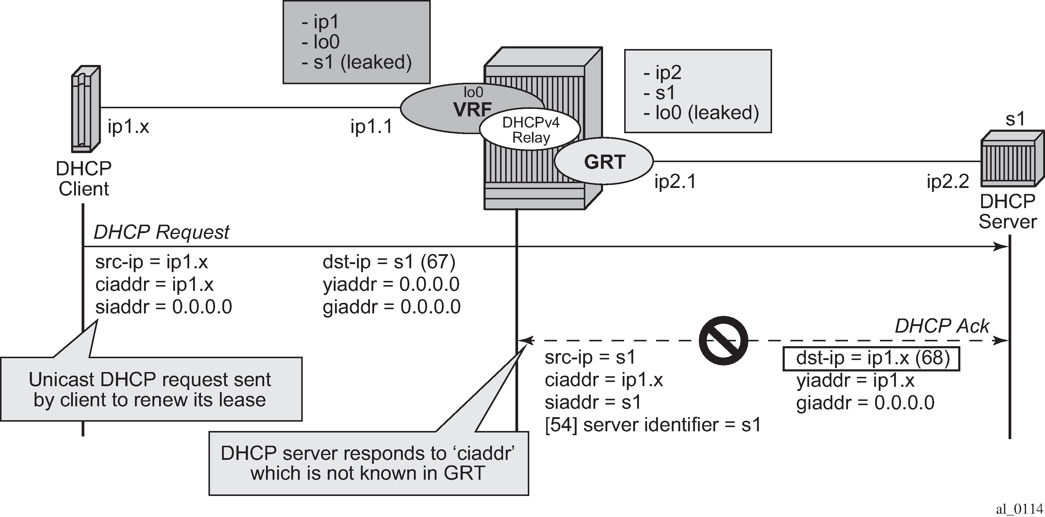
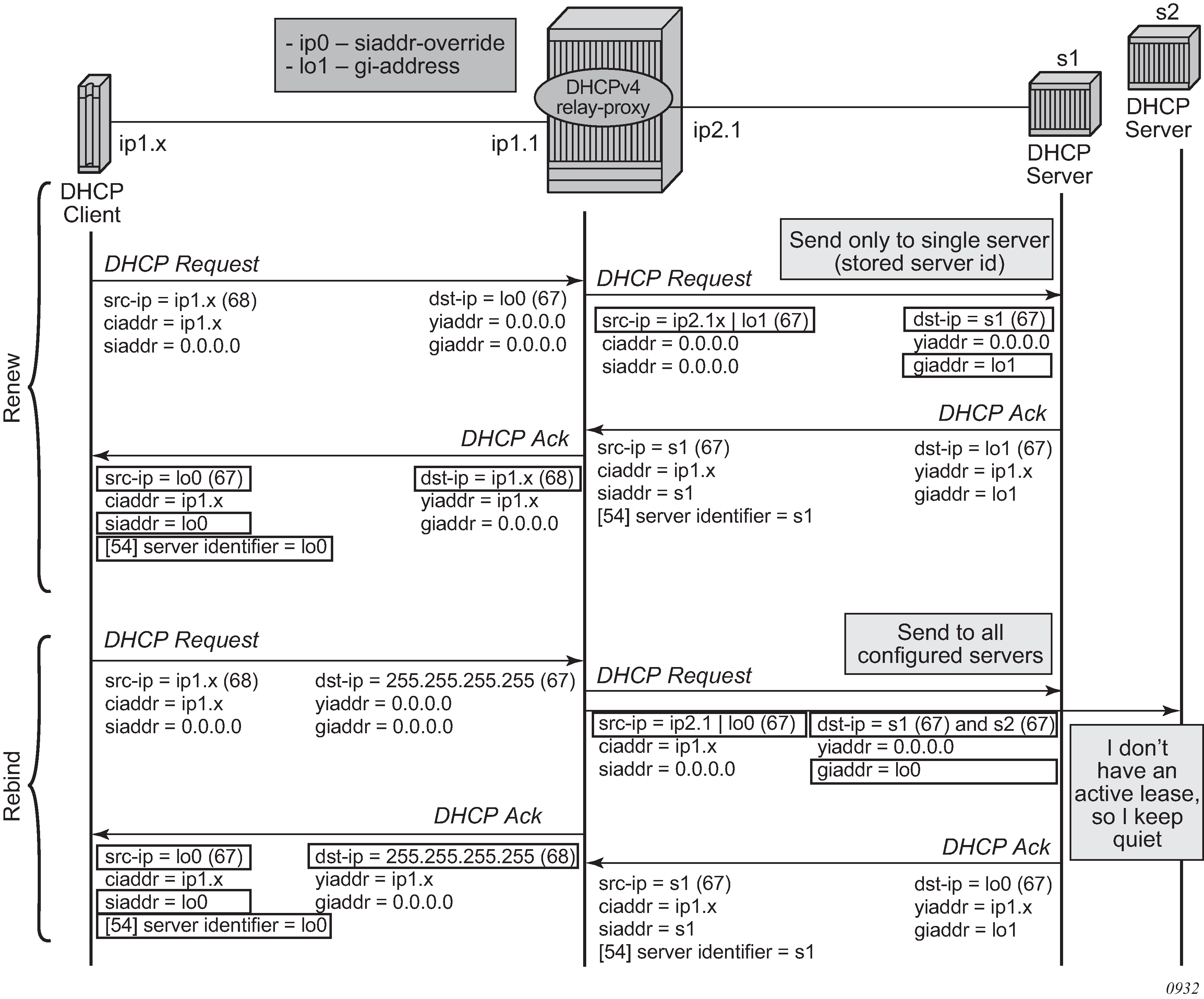
DHCPv4 relay proxy
In network deployments where DHCPv4 client subnets cannot be leaked in the DHCPv4 server routing instance, unicast renewal messages (DHCP ACKs) cannot be routed in the DHCPv4 server routing instance, as shown in Unicast renewal routing problem. The DHCP server sets the destination IP address of the DHCP ACK to the client IP address (ciaddr) as received in the DHCP REQUEST message. Because there is no route available for the client subnet in the DHCP server routing instance, the DHCP ACK cannot be delivered.
The unicast renewal routing problem shown in Unicast renewal routing problem can be solved with a relay proxy function that enhances the DHCPv4 relay. Use the following command to resolve this problem.
- MD-CLI
configure service ies interface ipv4 dhcp relay-proxy configure service ies subscriber-interface group-interface ipv4 dhcp relay-proxy configure service ies subscriber-interface ipv4 dhcp relay-proxy configure service ies interface ipv4 dhcp relay-proxy configure service ies subscriber-interface group-interface ipv4 dhcp relay-proxy configure service ies subscriber-interface ipv4 dhcp relay-proxy - classic
CLI
configure service ies interface dhcp relay-proxy
configure service ies subscriber-interface dhcp relay-proxy
configure service ies subscriber-interface group-interface dhcp relay-proxy
configure service vprn interface dhcp relay-proxy
configure service vprn subscriber-interface dhcp relay-proxy
configure service vprn subscriber-interface group-interface dhcp relay-proxy
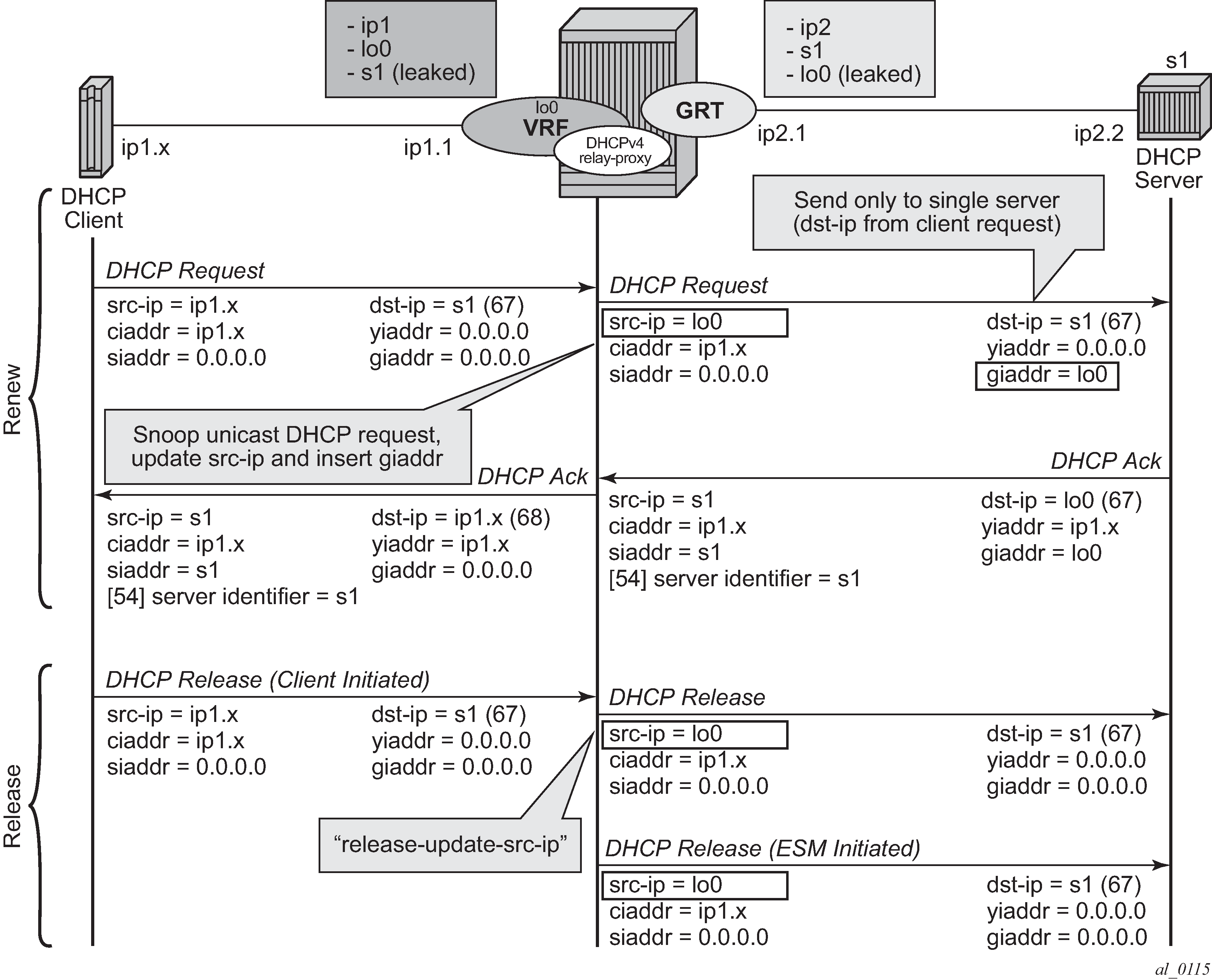
With the relay-proxy command in the DHCPv4 relay on a regular interface or group interface, the unicast renewals are now also relayed to the DHCPv4 server, as described below and shown in Relay unicast messages:
-
In the client to server direction, the source IP address is updated and the gateway IP address (gi-address) field is added before sending the message to the intended DHCP server (the message is not broadcasted to all configured DHCP servers.
-
In the server to client direction, the GI address field is removed and the destination IP address is updated with the value of the IP address (yiaddr) field.
When relay-proxy is enabled, the GI address can be configured to any local address that is configured in the same routing instance. The GI address is the only address that must be leaked in the DHCPv4 server routing instance because a DHCPv4 server always sends the response on a relayed packet to the relay agent using the gi-address as the destination IP address.
By default, unicast DHCPv4 RELEASE messages are forwarded transparently by a relay proxy function. The optional release-update-src-ip command option updates the source IP address with the value that is used for all relayed DHCPv4 messages, as shown in Relay unicast messages.
DHCPv4 FORCERENEW messages that are sent from a trusted external DHCPv4 server to a DHCPv4 relay agent configured as a relay proxy are forwarded to the DHCP client, if a corresponding DHCPv4 lease exists; otherwise, the DHCPv4 FORCERENEW messages are dropped.
The relay-proxy command can also be used to hide the DHCPv4 server address for DHCP clients. This prevents the client from learning the DHCPv4 server infrastructure details such as the IP address and number of servers. Hiding infrastructure details helps in Denial of Service (DoS) prevention.
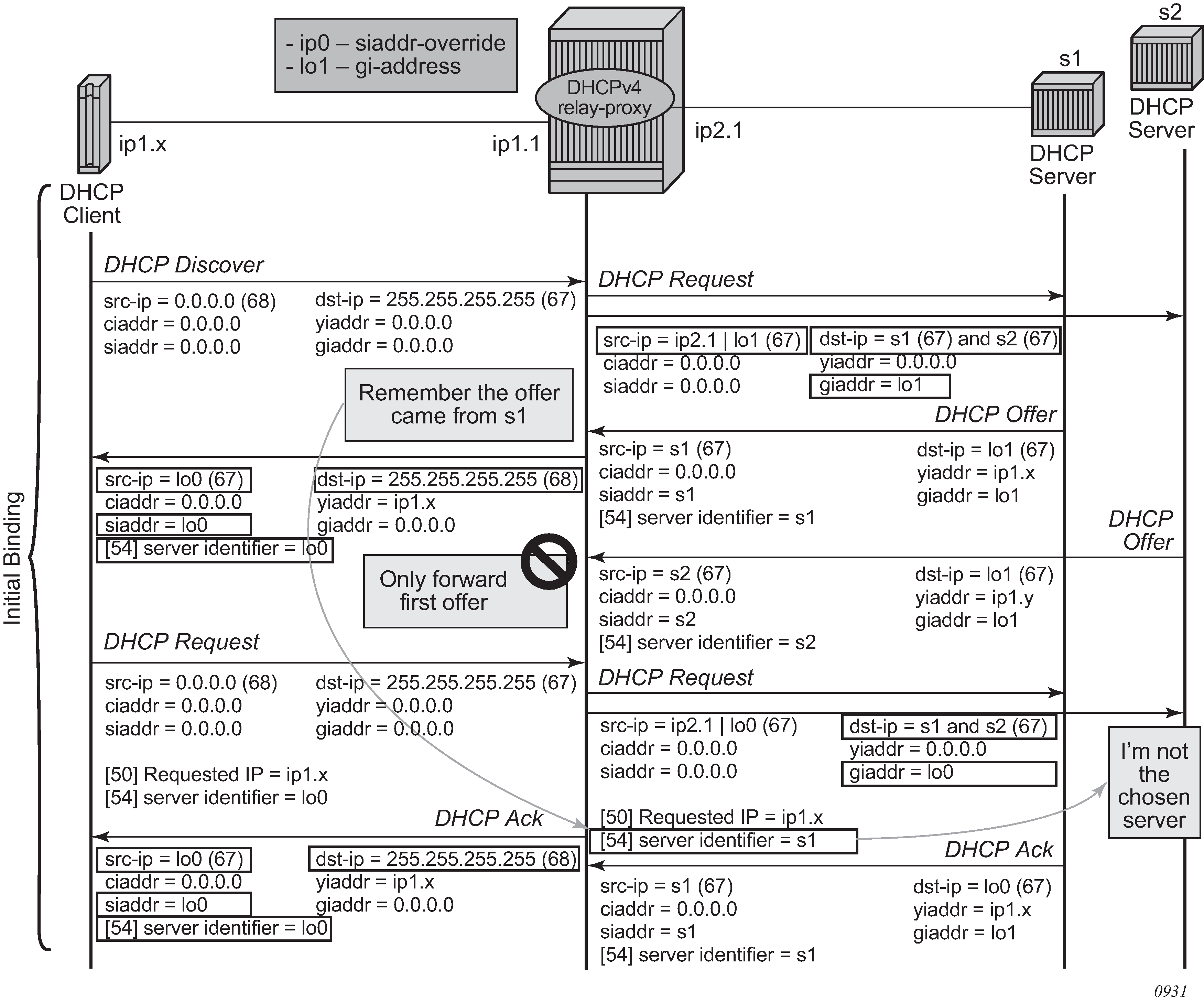
The optional siaddr-override command option in relay-proxy enables DHCPv4 server IP address hiding toward the client. The client interacts with the relay proxy as if it is the DHCP server. In addition to the relay proxy functions as described earlier, the following actions are performed when DHCPv4 server IP address hiding is configured:
-
In all DHCP messages to the client, the value of the following header fields and DHCP options containing the DHCP server IP address is replaced with the configured IP address:
-
the source IP address
-
the siaddr field in the DHCPv4 header if it is not equal to zero in the message received from the server
-
the Server Identification option (DHCPv4 option 54) if present in the original server message
-
-
The DHCP OFFER selection occurs during initial binding. Only the first DHCP OFFER message is forwarded to the client. Subsequent DHCP OFFER messages from different servers are silently dropped.
The siaddr-override command option can be any local address in the same routing instance. If DHCP relay lease split is enabled, siaddr-override command option has priority over the emulated-server configured in the proxy server and is used as the source IP address.
The active DHCPv4 server IP address obtained from the DHCP OFFER selection is required for the IP address hiding function and is stored in the lease state record. Therefore, the following command must be enabled on the interface when siaddr-override is configured.
- MD-CLI
configure service ies interface ipv4 dhcp lease-populate configure service ies subscriber-interface group-interface ipv4 dhcp lease-populate configure service vprn interface ipv4 dhcp lease-populate configure service vprn subscriber-interface ipv4 dhcp lease-populate configure service vprn subscriber-interface group-interface ipv4 dhcp lease-populate - classic
CLI
configure service ies interface dhcp lease-populate
configure service ies subscriber-interface group-interface dhcp lease-populate
configure service vprn interface dhcp lease-populate
configure service vprn subscriber-interface dhcp lease-populate
configure service vprn subscriber-interface group-interface dhcp lease-populate
DHCP server IP address hiding/initial binding shows the initial lease binding phase of a relay proxy with DHCP server address hiding enabled. In the absence of a DHCP lease state in the initial lease binding phase, the DHCP server IP address resulting from the OFFER selection is stored in a DHCP transaction cache. After successful lease binding, the DHCP server IP address is added to the lease state record.
In a host creation failure scenario, if no transaction cache or lease state is available when a DHCP REQUEST message is received, then the DHCP REQUEST is silently dropped. The drop reason can be found by enabling DHCP debug.
DHCP server IP address hiding/lease renewal shows the lease renewal phase of a relay proxy with DHCP server address hiding enabled. A unicast REQUEST (renew) is relayed only to the DHCP server owning the lease. A broadcast REQUEST (rebind) is relayed to all configured DHCP servers.
During lease renewal, the DHCP server IP address can be updated in the lease state if the DHCP ACK is received from a different server. This optimizes the DHCP proxy relay operation in a DHCP server failover scenario. This is shown in DHCP server IP address hiding, lease renewal with active server failure.

DHCP server IP address hiding, release shows the release in a relay proxy scenario with DHCP server address hiding enabled. The RELEASE message is sent only to the DHCP server owning the lease. Optionally, the source IP address can be updated.

Relay proxy can be enabled on subscriber group-interfaces and regular interfaces in an IES or VPRN service.
A relay proxy function is not supported with a double DHCPv4 relay (Layer 3 DHCPv4 relay in front of a DHCPv4 relay with relay-proxy enabled).
For retail subscriber interfaces, relay-proxy is configured as shown in the following example.
MD-CLI
[ex:/configure service vprn "1"]
A:admin@node-2# info
    customer "1"
    interface "lo0" {
        loopback true
        ipv4 {
            primary {
                address 192.0.2.10
                prefix-length 32
            }
        }
    }
    interface "lo1" {
        loopback true
        ipv4 {
            primary {
                address 192.0.2.11
                prefix-length 32
            }
        }
    }
    subscriber-interface "sub-int-1" {
        ipv4 {
            address 10.1.0.254 {
                prefix-length 24
            }
        }
        group-interface "group-int-1-1" {
            ipv4 {
                dhcp {
                    admin-state enable
                    server [172.16.1.1]
                    gi-address 192.0.2.11
                    src-ip-addr gi-address
                    lease-populate {
                        max-leases 32767
                    }
                    relay-proxy {
                        release-update-src-ip true
                        siaddr-override 192.0.2.10
                    }
                }
            }
        }
    }
classic CLI
A:node-2>config>service>vprn$ info
----------------------------------------------
            shutdown
            interface "lo0" create
                address 192.0.2.10/32
                loopback
            exit
            interface "lo1" create
                address 192.0.2.11/32
                loopback
            exit
            subscriber-interface "sub-int-1" create
                address 10.1.0.254/24
                group-interface "group-int-1-1" create
                    dhcp
                        server 172.16.1.1
                        lease-populate 32767
                        relay-proxy release-update-src-ip siaddr-override 192.0.2.10
                        gi-address 192.0.2.11 src-ip-addr
                        no shutdown
                    exit
                exit
            exit
----------------------------------------------
DHCP client
In the base router context, Ethernet ports can be configured with a router interface that supports a DHCP client. When the node operates as a DHCP client, it learns the IP address of the interface via dynamic IP address assignment. The DHCP client functionality is enabled by issuing the no shutdown command on the DHCP client in the configure router interface autoconfigure dhcp-client context. The following output shows an example of a router interface enabled as a DHCP client.
*A:DUT# config# router interface "station-wlan-ifc"
    port 1/4/4
    autoconfigure dhcp-client
        no shutdown
        exit
    exit
The 7705 SAR Gen 2 supports up to three DHCP clients per node .
When the DHCP client is enabled, changes to the DHCP client configuration take effect when the shutdown command is issued followed by the no shutdown command.
If DHCP relay configurations exist on the node, the DHCP client cannot be enabled until the DHCP relay configurations are removed. Similarly, if DHCP client configurations exist on the node, DHCP relay cannot be enabled until the DHCP client configurations are removed.
The DHCP client only supports IPv4.
When the DHCP client first becomes operational, it learns an IP address from a remote DHCP server using a DHCP DISCOVER message.
The node only sends a DHCP DISCOVER message if:
-
the DHCP client is enabled and the router interface is operationally up. Shutting down the DHCP client forces the release of the IP address.
-
a DHCP NAK message is received from the DHCP server that invalidates the previous DHCP DISCOVER message or any existing lease
When a DHCP client is shut down, all cached values (such as IP addresses and DHCP options) are cleared. They are rediscovered by issuing the no shutdown command.
If the port comes operationally up while the DHCP client is enabled and a DHCP discovery was not previously completed or a DHCP release was previously issued, then DHCP discovery is performed. If the port comes operationally up while the DHCP client is enabled and there was a previously completed DHCP discovery, then the DHCP client performs a DHCP REQUEST using the previously cached DHCP information from the discovery.
The operator can force a rediscovery procedure by executing the restart command in the tools perform router autoconfigure dhcp-client interface context.
The requested DHCP lease time can be configured using the CLI; however, the DHCP server can override this value. The node tracks the DHCP lease time and sends a DHCP REQUEST when half the lease time has elapsed. An IP address lease can be renewed manually using the tools perform router autoconfigure dhcp-client interface lease-renew command.
If the router interface goes down, the DHCP client parameters are cached for the interface. When the interface comes back up, if an IP address has been allocated and the lease time has not expired, the DHCP router interface sends a DHCP REQUEST to confirm that it can continue to use the IP address associated with the lease.
DHCP options must be configured in the CLI to make use of options received by the DHCP server. Any options received from the DHCP server are ignored if the corresponding options are not specified in the CLI. The DHCP client options are router, static-route, and dns-server. They are configured in the config router interface autoconfigure dhcp-client request-options context.
The show router route-table protocol dhcp-client command can be used to view the active routes in the routing table that have been learned by the DHCP client. If the same route is received from more than one DHCP client, the route received from the DHCP server with the lowest ID (option 54) is installed in the route table.
The show router dns command can be used to view whether the DNS server has been configured to send request messages to the DHCP server. The node supports up to six DNS server entries learned by the DHCP clients. Only the first six DNS servers are stored by the node; any subsequent DNS servers that are learned are ignored.
The CLI provides the option to use the router from the DHCP OFFER as the default gateway. In some scenarios, the router that is reachable from the WLAN port or an Ethernet port is the default gateway. In other scenarios, the cellular interface has reachability to the default gateway. The DHCP client router option (under request-options) enables the router request option in the DHCP OFFER message. If the router option is enabled, the default gateway is assigned by the DHCP server.
The DHCP DISCOVER message sent from the node to the DHCP server contains the following options:
-
chaddr—the MAC address of the client, either the WLAN or Ethernet port
-
Option 51—the configured IP address lease time
-
Option 53—the DHCP message type (DISCOVER)
-
Option 60—a user-configurable vendor class identifier, either a hexadecimal string or an ASCII string
-
Option 61—a user-defined client identifier: a hexadecimal string, an ASCII string, an interface name, or the client MAC address
-
Option 55—the parameter request list:
-
Option 1—the subnet mask value
-
Option 3—the router option, a list of IP addresses for routers on the client subnet (unused if not enabled in the CLI)
-
Option 54—the DHCP server address
-
The DHCP OFFER message from the DHCP server must contain the following options at a minimum:
-
yiaddr—the DHCP router interface IP address
-
Option 1—the subnet mask value
-
Option 3—the router option, a list of IP addresses for routers on the client subnet
-
Option 51—the configured IP address lease time
-
Option 53—the DHCP message type (OFFER)
-
Option 54—the DHCP server address
When responding to the server DHCP OFFER or when extending the time of an existing lease, the DHCP REQUEST message sent from the node to the DHCP server contains the following options:
-
chaddr—the client MAC address
-
Option 50—the requested IP address; this address is the same as the address contained in the yiaddr field that was received in the DHCP OFFER message
-
Option 53—the DHCP message type (REQUEST)
-
Option 54—the DHCP server address; this address is the same as the address received in the OFFER message
-
Option 51—the IP address lease time; this value is the same as the lease time received in the OFFER message
-
Option 60—the vendor class identifier; this value is the same as the vendor class identifier in the DISCOVER message
-
Option 61—the client identifier; this value is the same as the client identifier in the DISCOVER message
-
Option 55—the parameter request list:
-
Option 1—the subnet mask value
-
Option 3—the router option (unused if not enabled in the CLI)
-
Option 6—the DNS server option (unused if not enabled in the CLI)
-
Option 54—the DHCP server address
-
Option 121—the static-route option (unused if not enabled in the CLI)
-
When the DHCP client is shut down, a DHCP RELEASE message is sent to the DHCP server.
For BGP peers to other nodes behind the WLAN AP, the BGP local address can be set using the router interface name where the DHCP client is configured so that changes in the interface address because of DHCP messages are reflected in the local address of BGP sessions using this interface as the local address.
Restrictions on configuring a router interface with DHCP client enabled
When a DHCP client is enabled on a router interface, the following protocols and services are supported on this interface:
- BGP with local-address set to this interface name
- Layer 3 VPRN services using mp-BGP
- Layer 2 VPLS/VPWS services using BGP-VPLS and BGP-VPWS
- Static routing using this interface as the next-hop
- IPsec secured interface
When a DHCP client is enabled on a router interface, the following commands cannot be configured in the configure router interface context:
-
address
-
secondary
-
dhcp
-
unnumbered
-
loopback
If any of the commands in the preceding list are enabled, the no shutdown command is not available for the DHCP client until the commands are removed.
Route policy option for DHCP client
Routes can be imported from the DHCP client to other routing protocols with the configure router policy-options policy-statement entry from protocol dhcp-client command.
GRE termination for services over a DHCP client
A router interface configured as a DHCP client supports the following service types: VLL, VPLS, and VPRN. These services use a GRE SDP as a transport tunnel.
When a DHCP client is enabled on a router interface and an address is learned by the client, there is no configuration required in order to terminate GRE SDPs on that interface IP address. GRE termination is enabled on a DHCP client address when the client learns the address.
IP versions
The SR OS implements IP routing functionality, providing support for IP version 4 (IPv4) and IP version 6 (IPv6). IP version 6 (RFC 1883, Internet Protocol, Version 6 (IPv6)) is a version of the Internet Protocol designed as a successor to IP version 4 (IPv4) (RFC-791, Internet Protocol). The changes from IPv4 to IPv6 affect the following categories:
expanded addressing capabilities
IPv6 increases the IP address size from 32 bits (IPv4) to 128 bits, to support more levels of addressing hierarchy, a much greater number of addressable nodes, and simpler autoconfiguration of addresses. The scalability of multicast routing is improved by adding a scope field to multicast addresses. Also, a new type of address called an anycast address is defined and is used to send a packet to any one of a group of nodes.
header format simplification
Some IPv4 header fields have been dropped or made optional to reduce the common-case processing cost of packet handling and to limit the bandwidth cost of the IPv6 header.
improved support for extensions and options
Changes in the way IP header options are encoded allows for more efficient forwarding, less stringent limits on the length of options, and greater flexibility for introducing new options in the future.
flow labeling capability
The capability to enable the labeling of packets belonging to particular traffic flows for which the sender requests special handling, such as non-default quality of service or ‟real-time” service, was added in IPv6.
authentication and privacy capabilities
Extensions to support authentication, data integrity, and (optional) data confidentiality are specified for IPv6.
The following figure shows the IPv6 header format.
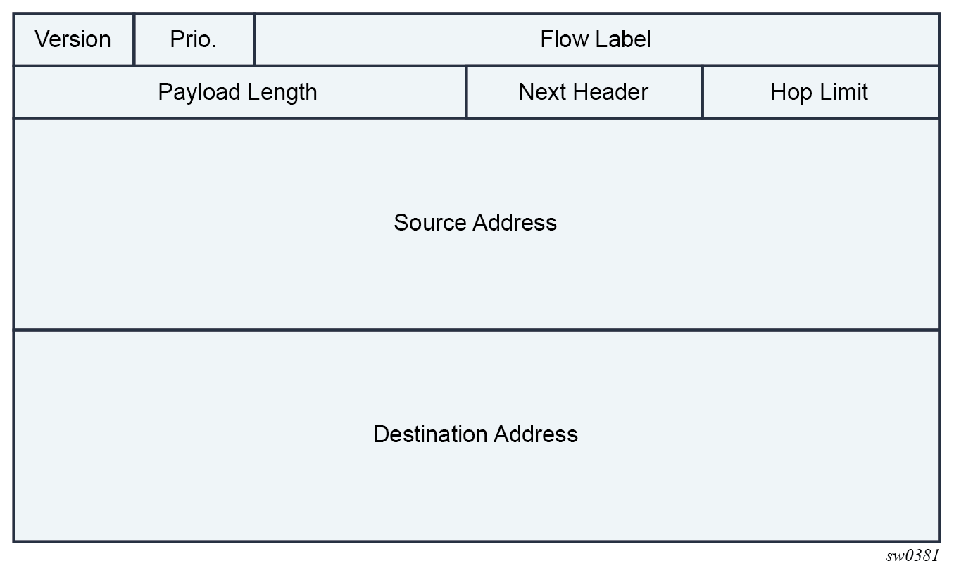
The following table lists IPv6 header fields and their descriptions.
| Field | Description |
|---|---|
Version |
4-bit Internet Protocol version number = 6. |
Prio. |
4-bit priority value. |
Flow Label |
24-bit flow label. |
Payload Length |
16-bit unsigned integer; the length of payload, for example, the rest of the packet following the IPv6 header, in octets; if the value is zero, the payload length is carried in a jumbo payload hop-by-hop option |
Next Header |
8-bit selector. Identifies the type of header immediately following the IPv6 header. This field uses the same values as the IPv4 protocol field. |
Hop Limit |
8-bit unsigned integer. Decremented by 1 by each node that forwards the packet. The packet is discarded if the hop limit is decremented to zero. |
Source Address |
128-bit address of the originator of the packet. |
Destination Address |
128-bit address of the intended recipient of the packet (possibly not the ultimate recipient if a routing header is present). |
IPv6 address format
IPv6 uses a 128-bit address, as opposed to the IPv4 32-bit address. Unlike IPv4 addresses, which use the dotted-decimal format, with each octet assigned a decimal value from 0 to 255, IPv6 addresses use the colon-hexadecimal format X:X:X:X:X:X:X:X, where each X is a 16-bit section of the 128-bit address. For example:
2001:0db8:0000:0000:0000:0000:0000:0000
Leading zeros must be omitted from each block in the address. A series of zeros can be replaced with a double colon. For example:
2001:db8::
The double colon can only be used one time in an address.
The IPv6 prefix is the part of the IPv6 address that represents the network identifier, which appears at the beginning of the address. The IPv6 prefix length, which begins with a forward slash (/), shows how many bits of the address make up the network identifier. For example, the address 2001:db8:8086:6502::1/64 means that the first 64 bits of the address represent the network identifier; the remaining 64 bits represent the node identifier.
IPv6 applications
Examples of the IPv6 applications supported by the SR OS include:
IPv6 Internet exchange peering
IPv6 Internet exchange shows an IPv6 Internet exchange where multiple ISPs peer over native IPv6
Figure 9. IPv6 Internet exchange 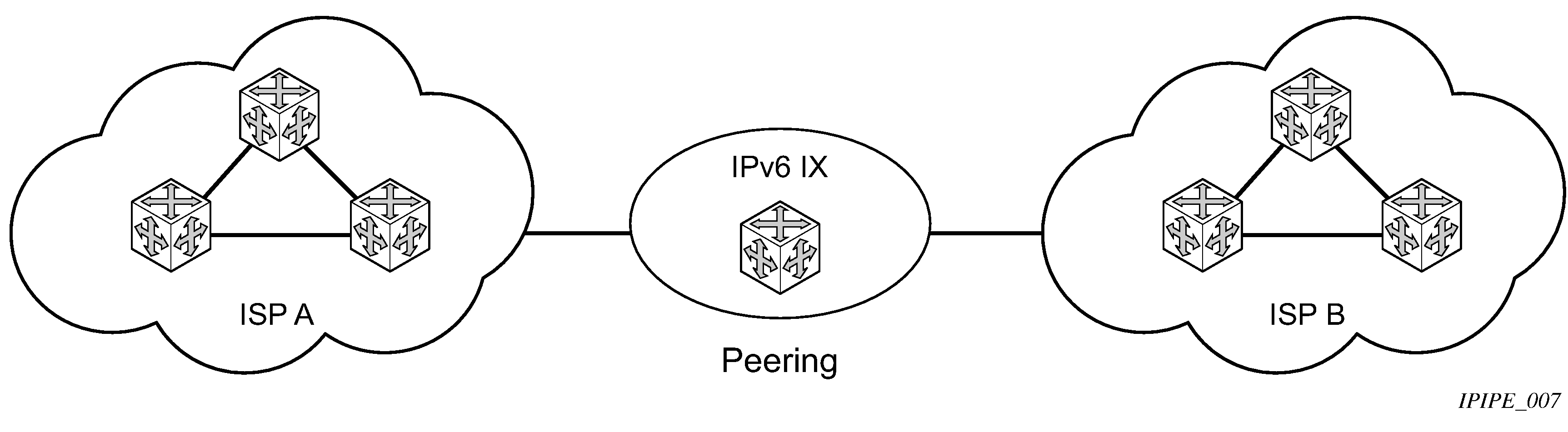
IPv6 transit services
IPv6 transit services shows IPv6 transit services provided by an ISP.
Figure 10. IPv6 transit services 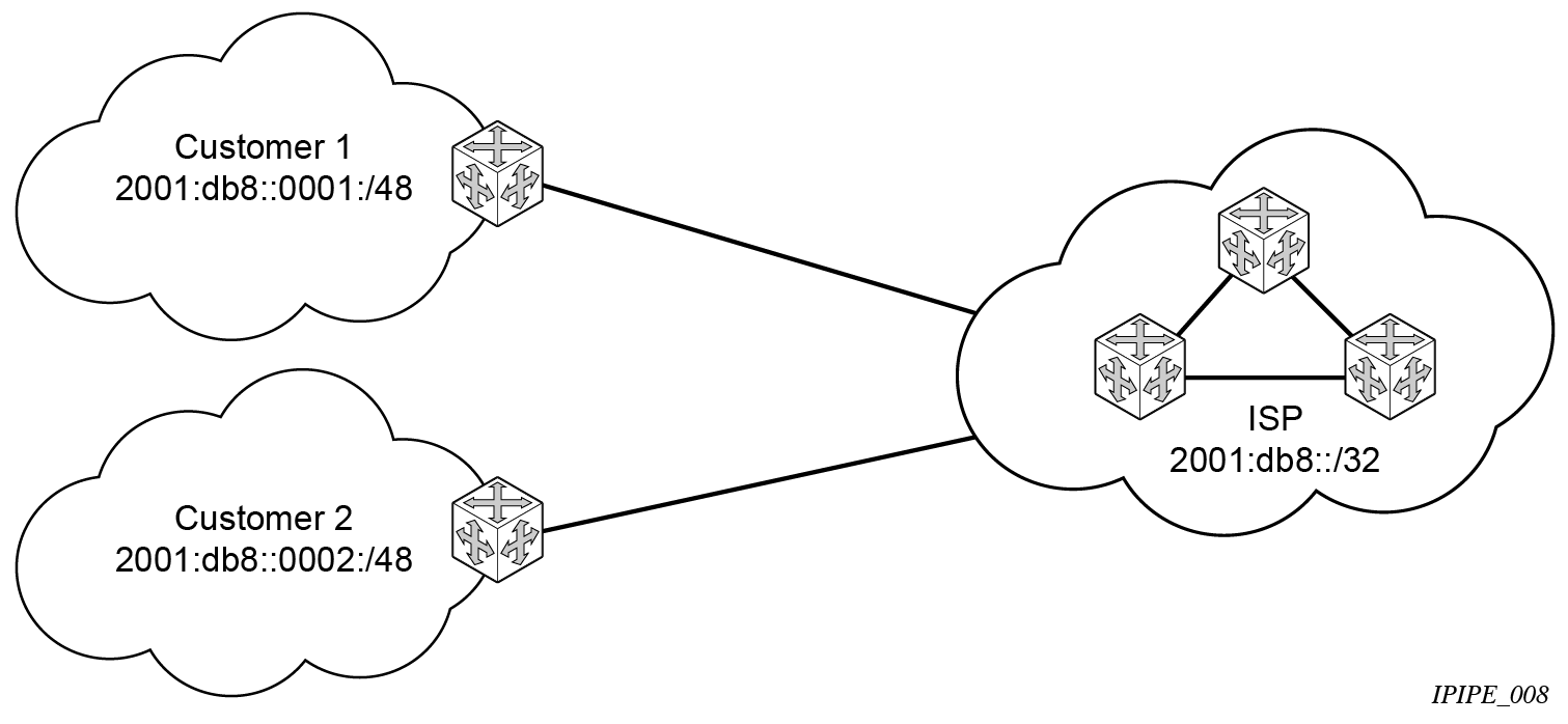
IPv6 services to enterprise customers and home users
IPv6 services to enterprise customers and home users shows IPv6 services to enterprise and home broadband users.
Figure 11. IPv6 services to enterprise customers and home users 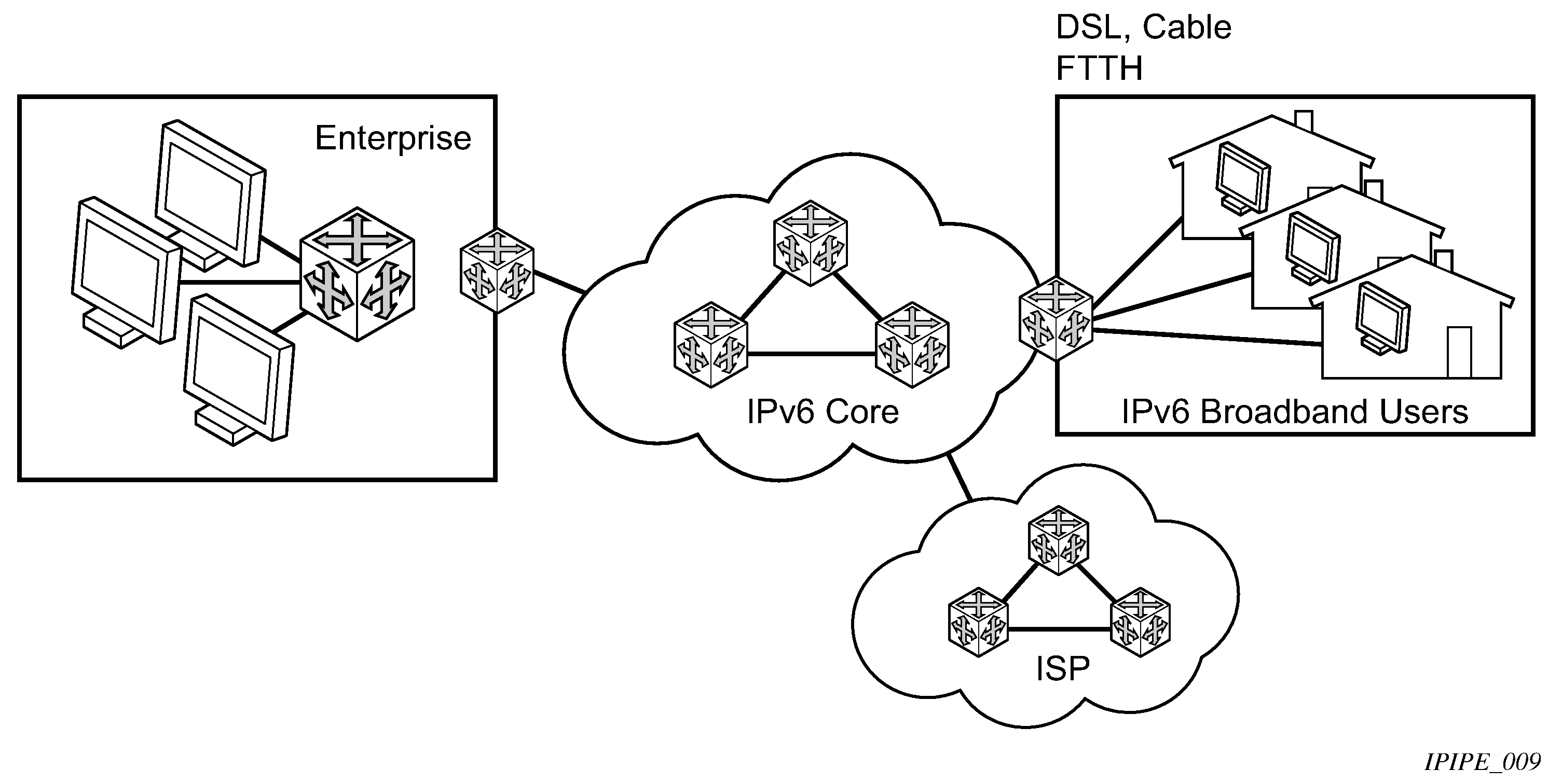
-
IPv6 over IPv4 relay services
IPv6 over IPv4 tunnels are one of many IPv6 transition methods to support IPv6 in an environment where not only IPv4 exists but native IPv6 networks depend on IPv4 for greater IPv6 connectivity. Nokia routers support dynamic IPv6 over IPv4 tunneling. The IPv4 source and destination address are taken from configuration, the source address is the IPv4 system address and the IPv4 destination is the next hop from the configured IPv6 over IPv4 tunnel.
IPv6 over IPv4 is an automatic tunnel method that gives a prefix to the attached IPv6 network. IPv6 over IPv4 tunnels shows IPv6 over IPv4 tunneling to transition from IPv4 to IPv6.
Figure 12. IPv6 over IPv4 tunnels 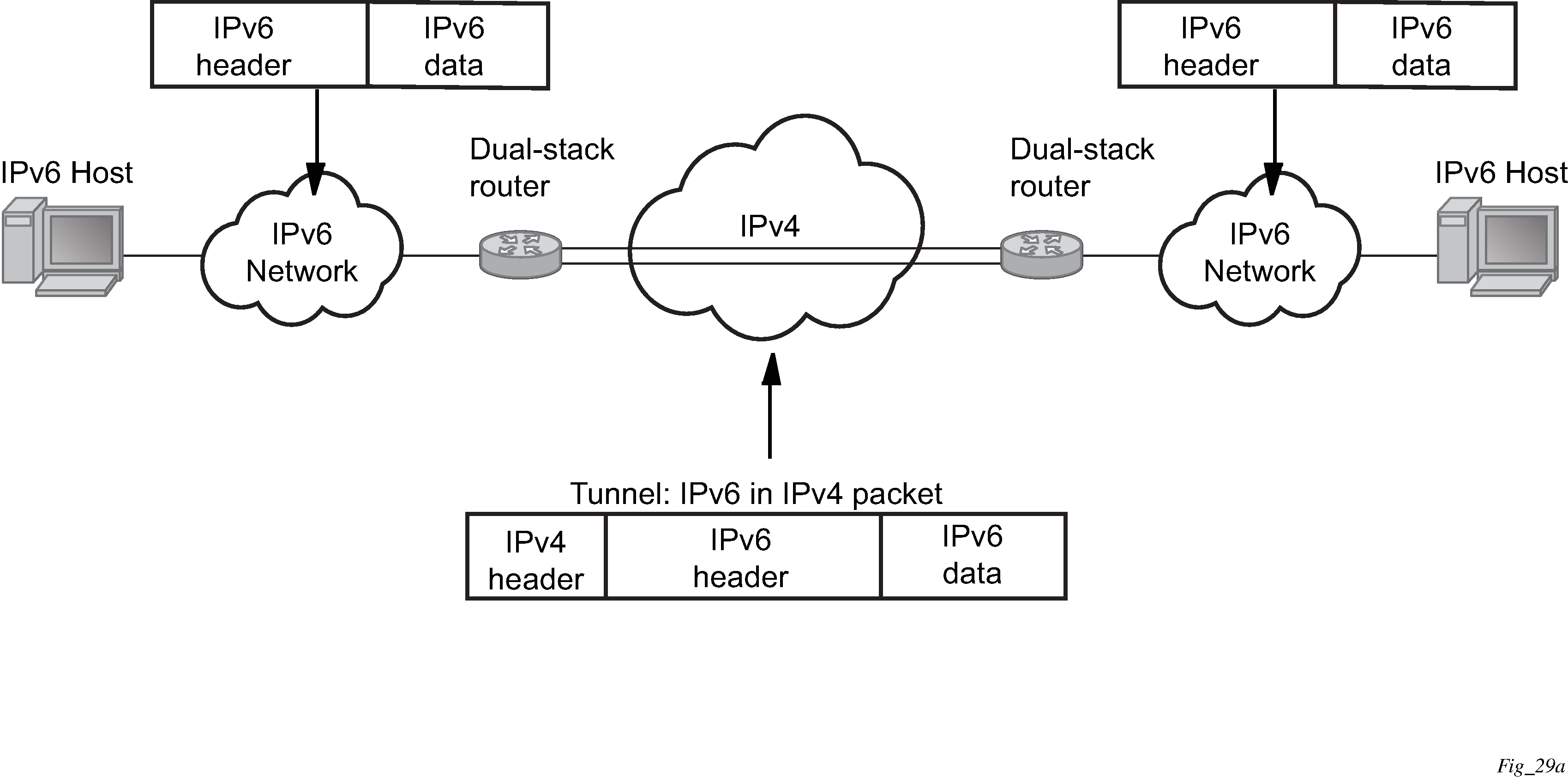
DNS
The DNS client is extended to use IPv6 as transport and to handle the IPv6 address in the DNS AAAA resource record from an IPv4 or IPv6 DNS server. An assigned name can be used instead of an IPv6 address because IPv6 addresses are more difficult to remember than IPv4 addresses.
DNS resolution using a VPRN
When using a management VPRN, to allow DNS resolution via VPRN, as an example, DNS for all packets—routed through the Global Routing Table or the VPRN—the user must enable a redirect VPRN configuration under the base DNS server.
Use the following command to enable the redirect VPRN configuration.
configure router dns redirect-vprn serviceWhen the redirect-vprn configuration is enabled, all packets have their URLs resolved through the configured redirect-vprn service. Only a single redirect-vprn configuration is supported.
As a prerequisite for the DNS resolution through the VPRN, the VPRN DNS server must be configured with at least a primary-dns IP address (IPv4 or IPv6). If the VPRN DNS server is not configured, all packet resolution fails, even if the BOF DNS server is configured, because the redirect-vprn configuration forces all packets through the redirect-vprn service for resolution.
The redirect-vprn command is not available at bootup, because the configuration is not loaded yet. Until the redirect-vprn command is executed, all DNS resolution is possible only through the BOF DNS configuration. The redirect-vprn configuration becomes active at runtime, after the configuration file is loaded and the redirect-vprn command is executed.
If the redirect-vprn command is not configured, DNS resolution occurs as follows:
-
The global routing packets use the BOF DNS server.
-
The VPRN packets use the configured VPRN DNS server. If the VPRN DNS server is not configured, the resolution occurs through the BOF DNS server.
For information about management VPRNs, see Node Management Using VPRN in the 7705 SAR Gen 2 Layer 3 Services Guide: IES and VPRN.
Secure Neighbor Discovery
Secure Neighbor Discovery (SeND) in conjunction with Cryptographically Generated Addresses (CGAs) allows users to secure IPv6 neighbor discovery between nodes on a common Layer 2 network segment.
When SeND is enabled on an interface, CGAs must be enabled and static GUA/LLA IPv6 addressing is not supported. In this case, the router generates a CGA from the configured prefix (GUA, LLA) and use that address for all communication. The router validates NS/ND messages from other nodes on the network segment, and only install them in the neighbor cache if they pass validation.
Several potential use-cases for SeND exist to secure the network from deliberate or accidental tampering during neighbor discovery, SeND can prevent hijacking of in-use IPv6 addressing or man-in-the-middle attacks, but also to validate whether a node is permitted to participate in neighbor discovery, or validate which routers are permitted to act as default gateways.
SeND affects the following areas of neighbor discovery:
Neighbor solicitation (solicited-node multicast address; target address)
Neighbor advertisement (solicited; unsolicited)
Router solicitation
Router advertisement
Redirect messages
Figure 13. Neighbor discovery with and without SeND 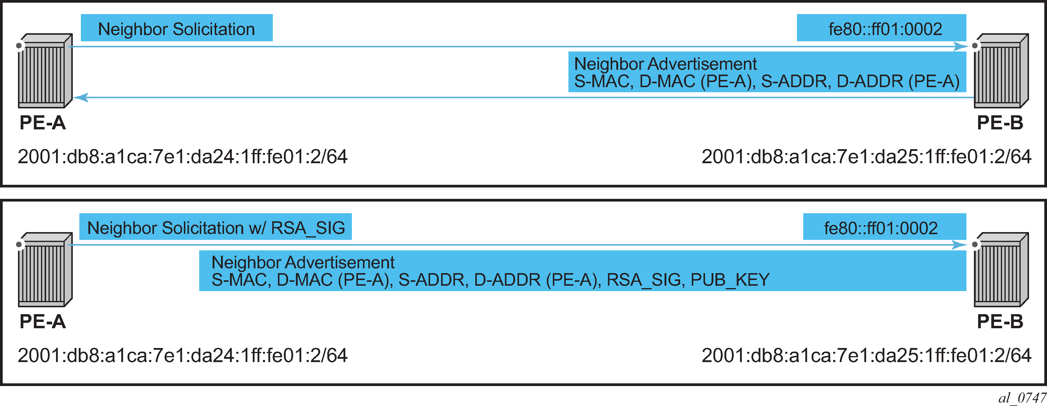
When SeND is enabled on a node, basic neighbor discovery messaging is changed as shown in Neighbor discovery with and without SeND. In the example, PE-A needs to find the MAC address of PE-B.
PE-A sends an NS message to the solicited node multicast address for PE-B's address with the CGA option, RSA signature option, timestamp option, and nonce option.
PE-B processes the NS message and, because it is configured for SeND operation, processes the NS. PE-B validates the source address of the packet to ensure it is a valid CGA, then validate the cryptographic signature embedded in the NS message.
PE-B generates an NA message, which is sent back to PE-A with the solicited bit, router bit set. The source address is that of PE-B, while the destination address is that of PE-A from the NS message. The timestamp is generated from PE-B, while the nonce is copied from PE-A's NS message.
PE-A receives the NA and completes similar checks as PE-B did.
If all steps process correctly, both nodes install each other’s addresses into their neighbor cache database.
SeND persistent CGAs
Persistent CGAs is a feature of SeND.
Previously, all generated CGAs on SeND-enabled interfaces remained unchanged after a CPM switchover, but after a reboot from a saved configuration file, all CGAs were regenerated.
To keep the same CGAs after a reboot from a saved configuration file:
Save the RSA key pair used for SeND.
Save the modifiers used during the CGA generation.
To make the CGAs persistent:
Import an online or offline generated RSA key pair for SeND.
Ensure that the CompactFlash (CF) files containing an RSA key pair that is used for SeND, are synchronized to the standby CPM by making use of the HA infrastructure used for certificates.
Ensure that the configuration file is saved when one or more CGAs are generated.
Persistent RSA key pair
The RSA key pair is stored in a file on the CF.
Generate an RSA key pair
Use the following command to generate an RSA key pair:
- MD-CLI
admin system security pki generate-key-pair rsa-key-size - classic
CLI
admin certificate gen-keypair type rsa size
The following example shows the generation of an RSA key pair. This generates a Distinguished Encoding Rules (DER) formatted file.
MD-CLI
[/admin system security pki]
A:admin@node-2# generate-keypair cf1:\myDir\myRsaKeyPair rsa-key-size 1024
classic CLI
*A:node-2# admin certificate gen-keypair cf1:\myDir\myRsaKeyPair type rsa size 1024
Import an online or offline generated RSA key pair
In the classic CLI, use the following command to import a generated RSA key pair.
admin certificate secure-nd-importThe following example shows the import of a generated RSA key pair.
classic CLI
*A:node-2# admin certificate secure-nd-import input cf1:\myDir\myRsaKeyPair output format derTake the following into consideration when configuring the RSA key pairs:
-
Because SeND only uses RSA key pairs, the command is refused if the imported key type is not RSA.
-
Because SeND only supports key size 1024, the command is refused if the imported key size is not 1024.
-
The password has to be specified when an offline generated file in pkcs12 format has to be imported.
-
See the RSA key pair rollover mechanism section that follows for more information about key-rollover.
-
In the classic CLI, use the following command to create the file cfx:\system-pki\secureNdKey (fixed directory and filename) and save the imported key in that file in encrypted per format same.
admin certificate import -
The RSA key pair is uploaded in the memory of SeND.
RSA key pair rollover mechanism
In the classic CLI, use the following command (described in the Import an online or offline generated RSA key pair section) to trigger a key rollover.
admin certificate secure-nd-importThe following example shows the triggering of a key rollover.
classic CLI
*A:node-2# admin certificate secure-nd-import cf1:\myDir\myOtherRsaKeyPair format der key-
rollover
Take the following into consideration when using the rollover mechanism:
-
If CGAs exist that are generated based on an autogenerated or previously imported RSA key pair and the key-rollover keyword is not specified, the secure-nd-import command is refused.
-
If a secure-nd-import with key-rollover is requested while a previous key rollover is still being handled, the new command is refused.
-
If the secure-nd-import command is accepted, the imported RSA key pair is written to the file cfx:\system-pki\secureNdKey and loaded to SeND. Existing CGAs, if any, are regenerated.
-
While handling a key rollover, SeND keeps track of which interface uses which RSA key pair. Temporarily, SeND can have two RSA key pairs in use. At all times, only the latest RSA key pair is stored in the file cfx:\system-pki\secureNdKey. When the rollover is finished, the RSA key pair that is no longer referred to, is deleted from SeND’s memory.
Autogeneration of an RSA key pair
The first time an interface becomes SeND enabled, SeND needs an RSA key pair to generate or check a modifier and to generate a CGA.
If the user did not import an RSA key pair for SeND, an autogenerated RSA key pair are used as a fallback.
The autogenerated RSA key pair is synchronized to the standby CPM, but is not written to the CF. Therefore, all CGAs generated via an autogenerated RSA key pair are not persistent. A warning is raised whenever a non-persistent CGA is generated.
In the classic CLI, the admin certificate secure-nd-import command without the key-rollover keyword is refused if CGAs exist that made use of the autogenerated RSA key pair. Specifying the key-rollover keyword results in regeneration of the CGAs.
See the section Making non-persistent CGAs persistent for more information about the procedure to make non-persistent CGAs persistent.
HA
For the synchronization of the RSA key pair file in cfx:\system-pki\ used by SeND, use the following commands for manual and automatic certificate synchronization:
- MD-CLIUse the following command to manually synchronize:
admin redundancy synchronize certificateUse the following command to automatically synchronize:configure redundancy cert-sync - classic CLIUse the following command to manually synchronize:
admin redundancy synchronize certUse the following command to automatically synchronize:configure redundancy cert-sync
SeND also synchronizes the RSA key pair to the standby CPM.
Persistent CGA modifier
The modifier used during the CGA generation is saved in the configuration file. The CGA itself is not stored.
Based on the stored modifier and RSA key pair, the same CGA can be regenerated.
The modifier is needed to be sent out in ND messages.
By storing the modifier in the configuration file, the user can also configure an offline generated modifier (possibly with a security parameter > 1).
Configure a SeND interface without modifiers (classic CLI)
A:node-2>config>router# info
#--------------------------------------------------
  "IP Configuration"
#--------------------------------------------------
        interface "itf1"
            address 10.10.10.1/24
            port 1/1/1
            ipv6
                secure-nd
                    no shutdown
A modifier is generated based on the actual RSA key pair (that is, imported or autogenerated). The offline modifier is used to generate a link-local CGA. The modifier is used to generate the global CGA.
exit
address 2000:1::/64
The modifier is saved in the interface configuration file.
Configure a SeND interface with modifiers (classic CLI)
*A:node-2>config>router# info
...
#--------------------------------------------------
echo "IP Configuration"
#--------------------------------------------------
        interface "itf2"
            address 10.10.10.2/24
            port 1/1/2
            ipv6
                secure-nd
                    link-local-modifier 0xABCD
...
The offline modifier is used to generate the link-local CGA.
no shutdown
exit
address 3000:1::/64 modifier
A modifier is generated based on the actual RSA key pair. The modifier is used to generate the global CGA.
The modifier is stored in the interface configuration file.
Stored modifier (classic CLI)
address 3000:2::/64 modifier 0xABCD
The same offline generated modifier as the preceding link-local address is used for the generation of a global address.
Modifier for generation of a global address (classic CLI)
address 3000:3::/64 modifier 0xABCD
Another offline generated modifier (*) is used for the generation of a global address.
For an offline generated modifier, a check is performed to see if it is generated with the actual RSA key pair and the security parameter applicable for the interface. If this check fails, the command is refused, unless the command is triggered in the context of an exec of a config file. In that case, the modifier is replaced by a new one that is generated based on the actual RSA key pair.
Making non-persistent CGAs persistent
CGAs can be non-persistent because:
-
The user forgot to configure an RSA key pair for SeND, therefore, the CGAs were generated based on an auto-generated RSA key pair.
-
The user forgot to synchronize an RSA key pair file to the stand-by CPM and a switchover happens.
-
The CGAs were generated by a software version not having persistent CGAs (such as, ISSU).
-
The system was booted from a configuration file generated by a software version not having persistent CGAs.
Key rollover
You can import a new RSA key pair for SeND with the key-rollover keyword. This results in the regeneration of all CGAs on all interfaces.
Exporting the SeND RSA key pair
Another method that does not result in the regeneration of the CGAs is to export the RSA key pair that is currently in use by SeND to the system-pki directory via an admin command.
In the classic CLI, use the following command to export the RSA key pair in use by SeND to the system-pki directory.
admin certificate secure-nd-importThis command writes the RSA key pair to the file cfx:\system-pki\secureNdKey in encrypted der format.
Booting from a saved configuration file
Configuration saved by a software version with persistent CGAs
The file cfx:\system-pki\secureNdKey should exist. This file is automatically uploaded by SeND during initialization.
The configuration file should contain a modifier for each address on a SeND enabled interface.
Modifiers in the configuration file are checked against the current RSA key pair. If the check fails, a new modifier and CGA is generated, and a warning is raised that a new CGA is generated.
If a modifier is missing from the configuration file for an IPv6 /64 prefix on a SeND enabled interface, a new modifier and CGA is generated based on the active RSA key pair.
Configuration saved by a software version having non-persistent CGAs
The file cfx:\system-pki\secureNdKey does not exist nor does the configuration file contain a modifier for any of the IPv6 /64 prefixes on secure-nd enabled interfaces.
New CGAs have to be generated (from the CLI context). Follow one of the procedures described in section Making non-persistent CGAs persistent to make the non-persistent CGA's persistent.
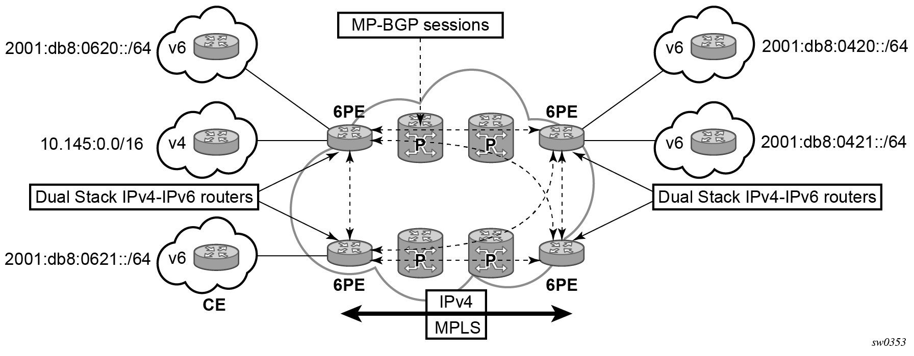
IPv6 Provider Edge over MPLS
The IPv6 Provider Edge (6PE) solution allows IPv6 domains to communicate with each other over an IPv4 MPLS core network. Because forwarding is based on MPLS labels, backbone infrastructure upgrades and core router reconfiguration is not required in this architecture. 6PE is a cost-effective solution for IPv6 deployment.
The following figure shows an example 6PE topology in an autonomous system (AS).
6PE control plane support
The 6PE MP-BGP routers support:
IPv4 and IPv6 dual-stack
MP-BGP to exchange IPv6 reachability information:
The 6PE routers exchange IPv6 reachability information using MP-BGP (AFI 2, SAFI 4).
An IPv4 address of the 6PE router is encoded as an IPv4-mapped IPv6 address in the BGP next-hop field. This is usually the IPv4 system address.
The 6PE router binds MPLS labels to the IPv6 prefixes it advertises. SR OS routers advertise the IPv6 explicit null (value 2) in advertised 6PE routes but accept any arbitrary label from peers.
-
The most preferred tunnel to the BGP next-hop allowed by the 6PE resolution filter is used to tunnel the traffic to the remote 6PE router. Use the following command to configure the 6PE resolution filter.
configure router bgp next-hop-resolution labeled-routes transport-tunnel family resolution-filter
6PE data plane support
The ingress 6PE router can push two or more MPLS labels to send the packets to the egress 6PE router. The top labels are associated with transport tunnel resolution. The remote 6PE router advertises the bottom label in MP-BGP. Typically, the IPv6 explicit null (value 2) label is used, but arbitrary values can be received when the remote 6PE router is not an SR OS router.
The egress 6PE router pops the top transport labels. When the IPv6 explicit null label is exposed, indicating that an IPv6 packet is encapsulated, the egress 6PE router pops the IPv6 explicit null label and performs an IPv6 route lookup to find the next hop for the IPv6 packet.
Static route resolution using tunnels
Use the commands in the following context to forward packets of a static route to an indirect next-hop over a tunnel programmed in TTM:
-
MD-CLI
configure router static-routes route indirect tunnel-next-hopIn the MD-CLI, if the tunnel-next-hop context is configured and resolution is set to none, the binding to the tunnel is removed and resolution resumes in RTM to IP next-hops.
-
classic CLI
configure router static-route-entry indirect tunnel-next-hopIn the classic CLI, if the tunnel-next-hop context is configured and resolution is set to disabled, the binding to the tunnel is removed and resolution resumes in RTM to IP next-hops.
If the resolution is set to any, any supported tunnel type in the static route context is selected following TTM preference.
The following tunnel types are supported in a static route context: LDP, RSVP-TE, Segment Routing (SR) Shortest Path, and Segment Routing Traffic Engineering (SR-TE):
-
LDP
The ldp command option instructs the code to search for an LDP LSP with a FEC prefix corresponding to the address of the indirect next-hop. Both LDP IPv4 FEC and LDP IPv6 FEC can be used as the tunnel next-hop. However, only an indirect next-hop of the same family (IPv4 or IPv6) as the prefix of the route can use an LDP FEC as the tunnel next-hop. In other words, an IPv4 (IPv6) prefix can only be resolved to an LDP IPv4 (IPv6) FEC.
-
RSVP-TE
The rsvp-te command option instructs the code to search for the set of lowest metric RSVP-TE LSPs to the address of the indirect next-hop. The LSP metric is provided by MPLS in the tunnel table. The static route treats a set of RSVP-TE LSPs with the same lowest metric as an ECMP set.
The user has the option of configuring a list of RSVP-TE LSP names to be used exclusively instead of searching in the tunnel table. In that case, all LSPs must have the same LSP metric in order for the static route to use them as an ECMP set. Otherwise, only the LSPs with the lowest common metric value are selected.
A P2P auto-lsp that is instantiated via an LSP template can be selected in TTM when resolution is set to any. However, it is not recommended to configure an auto-lsp name explicitly under the rsvp-te node as the auto-generated name can change if the node reboots, which blackholes the traffic of the static route.
-
SR shortest path
When the sr-isis or sr-ospf command options are enabled, an SR tunnel to the indirect next-hop is selected in the TTM from the lowest preference IS-IS or OSPF instance, and if many instances have the same lowest preference, it is selected from the lowest numbered IS-IS or OSPF instance. Both SR-ISIS IPv4 and SR-ISIS IPv6 tunnels can be used as tunnel next-hops. However, only an indirect next-hop of the same family (IPv4 or IPv6) as the prefix of the route can use an SR-ISIS tunnel as a tunnel next-hop. In other words, an IPv4 (IPv6) prefix can only be resolved to a SR-ISIS IPv4 (IPv6).
-
SR-TE
The sr-te command option instructs the code to search for the set of lowest metric SR-TE LSPs to the address of the indirect next-hop. The LSP metric is provided by MPLS in the tunnel table. The static route treats a set of SR-TE LSPs with the same lowest metric as an ECMP set.
The user has the option of configuring a list of SR-TE LSP names to be used exclusively instead of searching in the tunnel table. In that case, all LSPs must have the same LSP metric in order for the static route to use them as an ECMP set. Otherwise, only the LSPs with the lowest common metric value are selected.
Realize that the resolution filter, under static-route entry, does not validate the provided lsp-name type of the LSP against the requested filter context protocol type.
If one or more explicit tunnel types are specified using the resolution-filter command option, only these tunnel types are selected again following the TTM preference.
The user must set resolution to filter to activate the list of tunnel-types configured under resolution-filter.
If disallow-igp is enabled, the static route is not activated using IP next-hops in RTM if no tunnel next-hops are found in TTM.
Static route ECMP support
The following is the ECMP behavior of a static route:
-
ECMP is supported when resolving in RTM multiple static routes of the same prefix with multiple user-entered indirect IP next-hops. The system picks as many direct next-hops as available in RTM beginning from the first indirect next-hop and up to the value of the ecmp command option in the system.
-
ECMP is also supported when resolving in TTM a static route to a single indirect next-hop using a LDP tunnel when LDP has multiple direct next-hops.
-
ECMP is supported when resolving in TTM a static route to a single indirect next-hop using a RSVP-TE tunnel type when there is more than one RSVP LSP with the same lowest metric to the indirect next-hop.
-
ECMP is supported when resolving in TTM a static route to a single indirect next-hop using a list of user-configured RSVP-TE LSP names when these LSPs have the same metric to the indirect next-hop.
-
ECMP is supported when resolving in TTM multiple static routes of the same prefix with multiple user-entered indirect next-hops, each binding to a tunnel type. The system picks as many tunnel next-hops as available in TTM beginning from the first indirect next-hop and up to the value of the ecmp command option in the system. The spraying of flow packets is performed over the entire set of resolved next-hops that correspond to the selected indirect next-hops.
-
ECMP is supported when resolving concurrently in RTM and TTM multiple static routes of the same prefix with multiple user-entered indirect tunnel next-hops. There is no support for mixing IP and tunnel next-hops for the same prefix using different indirect next-hops. Tunnel next-hops are preferred over IP next-hops.
Static route using flexible algorithms tunnels
When configuring a static route toward an indirect next hop, the path selection based upon the constraints of a particular Flex-Algorithm should be considered. In such a use case, it is necessary to steer traffic into a corresponding flexible algorithm segment routing tunnel. This can be achieved with the tunnel-next-hop flex-algo command. This uses the specified flexible algorithm to construct a tunnel toward the indirect static-route next-hop.
The use of this command assumes that the router is participating in the flexible algorithm. This command instructs the router to lookup the indirect next-hop using flexible algorithm tunnels. The static route is not activated if a flexible algorithm-aware tunnel does not exist in the indirect next-hop.
When a router receives an IP packet, the static-route entry may steer toward the indirect next-hop using a flexible algorithm-aware SR tunnel, provided that such a tunnel exists. If the tunnel does not exist, the route is not active and the received IP packet is dropped, as long as no longest prefix match (LPM) route exists.
When the flex-algo command is configured, the resolution filter can only use matching flexible algorithm-aware SR tunnels created by flex-algo aware routing protocols (for example, SR IS-IS). If such an entry does not exist in the tunnel-table, the static-route entry does not become active.
Use the commands in the following context to configure static routes using flexible algorithms:
-
MD-CLI
configure router static-routes route indirect tunnel-next-hop flex-algo -
classic CLI
configure router static-route-entry indirect tunnel-next-hop
Aggregate next hop
This feature adds the ability to configure an indirect next-hop for aggregate routes. The indirect next-hop specifies where packets are forwarded if they match the aggregate route, but is not a more-specific route in the IP forwarding table.
Invalidate next-hop based on ARP/neighbor cache state
This feature invalidates next-hop entries for static routes when the next-hop is no longer reachable on directly connected interfaces. This invalidation is based on ARP and Neighbor Cache state information.
When a next-hop is detected as no longer reachable because of ARP/neighbor cache expiry, the route’s next-hop is set as unreachable to prevent the SR from sending continuous ARPs/neighbor solicitations triggered by traffic destined for the static route prefix. When the next-hop is detected as reachable via ARP or neighbor advertisements, the state of the next-hop is set back to valid.
Invalidate next-hop based on IPv4 ARP
This feature invalidates a static route based on the reachability of the next-hop in the ARP cache when the validate-next-hop command is enabled for an IPv4 static route. Use the commands in the following contexts to enable the validate-next-hop feature for an IPv4 static route:
-
MD-CLI
configure router static-routes route next-hop configure service vprn static-routes route next-hop -
classic CLI
configure router static-route-entry next-hop
configure service vprn static-route-entry next-hop
In this case, when the ARP entry for the next-hop is INVALID or not populated, the static route must remain invalid/inactive. When an ARP entry for the next-hop is populated based on a gratuitous ARP received or periodic traffic destined for it and the usual ARP who-has procedure, the static route becomes valid/active and is installed.
Invalidate next-hop based on neighbor cache state
This feature invalidates a static route based on the reachability of the next-hop in the neighbor cache when the validate-next-hop command is enabled for an IPv6 static route.
Use the commands in the following contexts to enable validate-next-hop for an IPv4 static route:
-
MD-CLI
configure router static-routes route next-hop configure service vprn static-routes route next-hop -
classic CLI
configure router static-route-entry next-hop
configure service vprn static-route-entry next-hop
In this case, when the Neighbor Cache entry for next-hop is INVALID or not populated, the static route must remain invalid/inactive. When an NC entry for next-hop is populated based on a neighbor advertisement received, or periodic traffic destined for it and the usual NS/NA procedure, the static route becomes valid/active and is installed.
IP interface strip-label behavior
The strip-label feature causes arriving MPLS encapsulated traffic to be stripped of all MPLS labels (up to five) before processing the packet through Policy Based Routing (PBR) filters. Use the following command to configure strip-label.
configure router interface strip-labelIf the packets do not have an IP header immediately following the MPLS label stack after the strip, they are discarded. Only MPLS encapsulated IP, IGP shortcuts, and VPRN over MPLS packets are processed. However, IPv4 and IPv6 packets that arrive without any labels are supported on an interface with strip label enabled.
The strip-label command operates in promiscuous mode. The router does not filter on the destination MAC address of the Ethernet frames. In some network designs, multiple ports may be tapped and combined into an interface toward the router. Promiscuous mode allows all of these flows to be processed without requiring the destination MAC address to be updated to match the router address.
To associate an interface that is configured with the strip-label command with a port, the port must be configured as single-fiber.
Packets subject to the strip-label action and mirrored (using mirrors or Lawful Intercept) contain the original MPLS labels (and other Layer 2 encapsulation) in the mirrored copy of the packet, as they appeared on the wire when the mirror-dest type is the default type “ether”. If the mirror-dest type is “ip-only”, the mirrored copy of the packet does not contain the original Layer 2 encapsulation or the stripped MPLS labels.
This command is supported on:
- optical ports for the 7705 SAR Gen 2
- null/dot1q encaps
- network ports
- IPv4
- IPv6
LDP shortcut for IGP route resolution
This feature enables you to forward user IP packets and specified control IP packets using LDP shortcuts over all network interfaces in the system that participate in the IS-IS and OSPF routing protocols. The default is to disable the LDP shortcut across all interfaces in the system.
Use the following commands to use LDP shortcuts for IGP route resolution:
-
MD-CLI
configure router ldp ldp-shortcut ipv4 configure router ldp ldp-shortcut ipv6 -
classic CLI
configure router ldp-shortcut [ipv4][ipv6]
IGP route resolution
When LDP shortcut is enabled, LDP populates the RTM with next-hop entries corresponding to all prefixes for which it activated an LDP FEC. For an activated prefix, two route entries are populated in RTM. One corresponds to the LDP shortcut next-hop and has an owner of LDP. The other one is the regular IP next-hop. The LDP shortcut next-hop always has preference over the regular IP next-hop for forwarding user packets and specified control packets over a specific outgoing interface to the route next-hop.
The prior activation of the FEC by LDP is done by performing an exact match with an IGP route prefix in RTM. It can also be done by performing a longest prefix match with an IGP route in RTM if the aggregate-prefix-match command option is enabled globally in LDP.
The LDP next-hop entry is not exported to the LDP control plane or to any other control plane protocols except OSPF, IS-IS, and an OAM control plane specified in Handling of control packets.
This feature is not restricted to /32 IPv4 prefixes or /128 IPv6 FEC prefixes. However, only /32 IPv4 and /128 IPv6 FEC prefixes are populated in the tunnel table for use as a tunnel by services.
All user and specified control packets for which the longest prefix match in RTM yields the FEC prefix are forwarded over the LDP LSP. The following is an example of the resolution process.
Assume that the egress LER advertised a FEC for some /24 prefix using the fec-originate command. At the ingress LER, LDP resolves the FEC by checking in RTM that an exact match exists for this prefix. After the LDP activates the FEC, it programs the NHLFE in the egress datapath and the LDP tunnel information in the ingress datapath tunnel table.
Next, LDP provides the shortcut route to RTM, which associates it with the same /24 prefix. There are two entries for this /24 prefix: the LDP shortcut next-hop and the regular IP next-hop. The latter was used by LDP to validate and activate the FEC. RTM then resolves all user prefixes that succeed a longest prefix match against the /24 route entry to use the LDP LSP.
Now assume that the aggregate-prefix-match was enabled and that LDP found a /16 prefix in RTM to activate the FEC for the /24 FEC prefix. In this case, RTM adds a new, more-specific route entry of /24 and has the next-hop as the LDP LSP. However, RTM does not have a specific /24 IP route entry. RTM then resolves all user prefixes that succeed a longest prefix match against the /24 route entry to use the LDP LSP. All other prefixes that succeed a longest prefix match against the /16 route entry uses the IP next-hop. LDP shortcut also works when using RIP for routing.
LDP-IGP synchronization
See the 7705 SAR Gen 2 MPLS Guide for information about LDP-IGP synchronization.
LDP shortcut forwarding plane
After the LDP activates an FEC for a prefix and programs RTM, it also programs the ingress tunnel table in IOM or online cards with the LDP tunnel information.
When an IPv4 packet is received on an ingress network interface, a subscriber IES interface, or a regular IES interface, the lookup of the packet by the ingress IOM or line card results in the packet being sent labeled with the label stack corresponding to the NHLFE of the LDP LSP when the preferred RTM entry corresponds to an LDP shortcut.
If the preferred RTM entry corresponds to an IP next-hop, the IPv4 packet is forwarded unlabeled.
The switching from the LDP shortcut next-hop to the regular IP next-hop when the LDP FEC becomes unavailable depends on whether the next-hop is still available. If it is (for example, the LDP FEC was withdrawn because of LDP control plane issues) the switchover should be faster. If the next-hop determination requires IGP to re-converge, this takes longer. However, no target is set.
The switching from a regular IP next-hop to an LDP shortcut next-hop usually occurs only when both are available. However, the programming of the NHLFE by LDP and the programming of the LDP tunnel information in the ingress IOM or line cards tunnel table are asynchronous. If the tunnel table is configured first, it is possible that traffic is black-holed for some time.
ECMP considerations
When ECMP is enabled and multiple equal-cost next-hops exist for the IGP route, the ingress IOM or line card sprays the packets for this route based on the hashing routine currently supported for IPv4 packets.
When the preferred RTM entry corresponds to an LDP shortcut route, spraying is performed across the multiple next-hops for the LDP FEC. The FEC next-hops can either be direct link LDP neighbors or T-LDP neighbors reachable over RSVP LSPs, in the case of LDP-over-RSVP, but not both. This is as per ECMP for LDP.
When the preferred RTM entry corresponds to a regular IP route, spraying is performed across regular IP next-hops for the prefix.
Spraying across regular IP next-hops and LDP-shortcut next-hops concurrently is not supported.
Handling of control packets
All control plane packets do not see the LDP shortcut route entry in RTM with the exception of the following control packets, which are forwarded over an LDP shortcut when enabled:
A locally generated or in transit ICMP ping and trace route of an IGP route. The transit message appears as a user packet to the ingress LER node.
A locally generated response to a received ICMP ping or trace route message.
All other control plane packets that require an RTM lookup and knowledge of which destination is reachable over the LDP shortcut continues to be forwarded over the IP next-hop route in RTM.
Handling of multicast packets
Multicast packets cannot be forwarded or received from an LDP LSP. This is because there is no support for the configuration of such an LSP as a tunnel interface in PIM. Only an RSVP P2MP LSP is currently allowed.
If a multicast packet is received over the physical interface, the uRPF check does not resolve to the LDP shortcut because the LDP shortcut route in RTM is not made available to multicast application.
Interaction with BGP route resolution to an LDP FEC
There is no interaction between an LDP shortcut for BGP next-hop resolution and the LDP shortcut for IGP route resolution. BGP continues to resolve a BGP next-hop to an LDP shortcut if the user enabled the following command option in BGP. The following example shows the configuration to enable the resolution of a BGP next-hop to an LDP shortcut.
MD-CLI
[ex:/configure router "Base" bgp next-hop-resolution shortcut-tunnel]
A:admin@node-2# info
    family ipv4 {
        resolution-filter {
            ldp true
        }
    }
classic CLI
A:node-2>config>router>bgp>next-hop-res>shortcut-tunn# info
----------------------------------------------
                family ipv4
                    resolution-filter
                        ldp
                    exit
                exit
----------------------------------------------
Interaction with static route resolution to an LDP FEC
A static route continues to be resolved by searching an LDP LSP whose FEC prefix matches the specified indirect next-hop for the route. In contrast, the LDP shortcut for IGP route resolution uses the LDP LSP as a route. The most specific route for a prefix is selected and, if both a static and IGP routes exist, the RTM route type preference is used to select one.
LDP control plane
For the LDP shortcut to be usable, SR OS must originate a <FEC, label> binding for each IGP route it learns of even if it did not receive a binding from the next-hop for that route. The router must assume that it is an egress LER for the FEC until the route disappears from the routing table or the next-hop advertises a binding for the FEC prefix. In the latter case, SR OS becomes a transit LSR for the FEC.
SR OS originates a <FEC, label> binding for its system interface address only by default. The only way to originate a binding for local interfaces and routes that are not local to the system is by using the fec-originate capability.
Use the fec-originate command to generate bindings for all non-local routes for which this node acts as an egress LER for the corresponding LDP FEC. Specifically, this feature must support the FEC origination of IGP learned routes and subscriber/host routes statically configured or dynamically learned over subscriber IES interfaces.
An LDP LSP used as a shortcut by IPv4 packets may also be tunneled using the LDP-over-RSVP feature.
Weighted load-balancing over interface next-hops
When the weighted-ecmp command is configured in the base router context or a VPRN, any IPv4 or IPv6 static, IS-IS, or OSPF route associated with the routing instance can be programmed into the datapath to use weighted load-balancing across the interface next-hops of the route.
Use the following commands to configure weighted ECMP in the base router context or in a VPRN.
configure router weighted-ecmp
configure service vprn weighted-ecmp
In order for weighted ECMP to be supported across the interface next-hops of an IS-IS or OSPF route the following conditions must be met.
-
All of the calculated ECMP next-hops must be interface next-hops.
-
All of the calculated ECMP next-hop interfaces must have a non-zero load-balancing-weight value configured in the following context. Use the commands in the following context to configure a non-zero load-balancing-weight value.
configure router isis interfaceBy default, IS-IS or OSPF interfaces have a zero weight (no load-balancing-weight); non-zero values must be configured explicitly. Values cannot be auto-derived.
In order for weighted ECMP to be supported across the interface next-hops of a static route the following conditions must be met.
-
All of the configured ECMP next-hops must be direct next-hops (resolved to an interface). The ECMP next-hops are the next-hops with the lowest preference that also have the lowest metric.
-
All of the configured ECMP next-hop interfaces must have a non-zero load-balancing-weight value configured in the following context. Use the commands in the following context to configure a non-zero load-balancing-weight value:
-
MD-CLI
configure router static-routes route next-hop -
classic CLI
configure router static-route-entry next-hop
By default, static route next-hops have a zero weight (no load-balancing-weight); non-zero values must be configured explicitly. Values cannot be auto-derived. The ECMP next-hops are the next-hops with the lowest preference that also have the lowest metric.
-
The load-balancing-weight commands in the IS-IS or OSPF and static route configuration trees accept a value between 0 and 4294967295.
If an IPv4 or IPv6 BGP route has a BGP next-hop resolved by a static, IS-IS, or OSPF ECMP route and ibgp-multipath is configured under BGP, traffic forwarded to the BGP next-hop is sprayed according to the load-balancing-weights of the interface next-hops.
IP FRR for static route entry
IP Fast ReRoute (FRR) is supported when the backup-next-hop command is configured for a static route entry. IP FRR support uses 1+1 protection by using a single backup next-hop address when the single primary next-hop fails. Only 1+1 protection is supported during backup without ECMP capability. Next-hop forwarding information for the backup next-hop address from the IP Routing Table Manager (RTM) is used to install a pre-resolved IP or tunneled fast reroute backup path to the backup next-hop. The configured backup next-hop IP address can be directly or indirectly connected through an IGP, a BGP, or a tunnel. The backup next-hop must be of the same IP address family as the primary next-hop (for example, an IPv4 primary next-hop can be protected using an IPv4 backup next-hop).
IP FRR for static route is supported in the base router and service VPRN contexts.
If the primary next-hop of the static route entry fails and the IP FRR backup next-hop is activated, then the backup tag is applied to the static route and the configured preference and metric for the primary hop is inherited. If the primary next-hop is activated again, then make-before-break functionality is used to avoid any packet loss.
The following example shows the IP FRR configuration.
MD-CLI
[ex:/configure router "Base"]
A:admin@node-2# info
    static-routes {
        route 10.10.0.0/16 route-type unicast {
            tag 20
            backup-tag 100
            next-hop "101.1.1.1" {
                preference 100
                backup-next-hop {
                    address 50.1.1.2
                }
            }
        }
    }
classic CLI
A:node-2>config>router# info
#--------------------------------------------------
"Static Route Configuration"
#--------------------------------------------------
        static-route-entry 10.10.0.0/16
            tag 20
            backup-tag 100
            next-hop 101.1.1.1
                preference 100
                backup-next-hop
                    address 50.1.1.2
                exit
            exit
        exit
The logic behavior applied to the associated tag of the static route entry is summarized in the following table.
| Primary NH | Backup NH | StaticRoute State | StaticRoute Tag |
|---|---|---|---|
|
UP |
UP |
UP |
201 |
|
UP |
DOWN |
UP |
201 |
|
DOWN |
UP |
UP |
1001 |
|
DOWN |
DOWN |
DOWN |
— |
IGP export policies can use the tag and the backup-tag as match criteria when exporting a static route entry using route policies. The export policies may introduce unique export properties for each tag (for example, resulting in different IGP metrics) and may make an exported route more or less desirable when the primary next-hop fails and the backup next-hop is activated.
The following limitations apply in the IP FRR for static route entries.
-
Only the primary next-hop has IP FRR support. The backup next-hop has no IP FRR support if it suddenly becomes unreachable.
-
If multiple next-hops are configured with a backup for a static route entry, then IP FRR is activated if there is only one remaining primary next-hop active. If multiple primary next-hops can be activated, then the static route entry uses ECMP and the backup next-hop IP FRR functionality is not used.
-
If the primary next-hop fails and the backup next-hop is used as the primary hop, then the backup next-hop uses the configured backup tag (or 0, if not configured) and inherits the configured preference and metric of the primary next-hop (or the default values, if not configured).
-
The backup inherits the preference and the metric of the primary next-hop, however, it does not support any of the features configured on the primary next-hop (for example, BFD, CPE check, LDP sync, and so on) even when the backup becomes the active next-hop.
-
If the primary next-hop of a static route entry, configured with a backup next-hop, is held down because hold-down is configured on static routes, the backup next-hop is also held down and is not used for traffic, even in cases where the backup-next-hop can be activated.
-
The following tunnel types are supported:
-
OSPF or ISIS shortcuts using RSVP-TE and SR-TE
-
BGP VPN-v4/v6 or BGP shortcut routes over LDP, RSVP, SR-ISIS, SR-OSPF, LDPoRSVP, SR-TE, GREv4, SR policy, MPLS forward policy, and RIB API
-
backup-next-hop recursion through indirect next-hop static-route-entry with resolution filter for LDP, RSVP, LDPoRSVP, SR-TE, SR-ISIS, SR-OSPF, SR policy, MPLS forward policy, or RIB API
-
-
LDP-FRR using a static-route is not mutually supported in combination with static-route backup-next-hop for the same static route.
-
Any other backup-next-hop types are considered as non-supported. For example:
-
Locally aggregated BGP routes
-
BGP routes when the BGP next-hop is recursively resolved through another BGP route
-
6over4 tunnel
-
GREv6 tunnel
-
OSPF or IS-IS shortcuts using LDP, SR-ISIS, SR-OSPF, and LDPoRSVP (generic IGP shortcut limitation not only for backup-next-hop)
-
OSPF or IS-IS shortcuts over SR policy, MPLS forward policy, and RIB API (generic IGP shortcut limitation not only for backup-next-hop)
-
BGP-LU over LDP, RSVP, LDPoRSVP, SR-TE, SR-OSPF, SR-ISIS, SR policy, MPLS forward policy and RIB API
-
4PE
-
6PE
-
Router interface encryption with NGE
NGE nodes support Layer 3 encryption on router interfaces for IPv4 traffic. NGE is not supported on dual-stack IPv4/IPv6 or IPv6-only interfaces. See the 7705 SAR Gen 2 Services Overview Guide for more information about platforms that support NGE.
NGE is enabled on a router interface by configuring the group-encryption command on the router interface. The interface is considered part of the NGE domain, and any received packets that are NGE-encrypted are decrypted if the key group is configured on the node. To encrypt packets egressing the interface, the outbound key group must be configured on the interface. All IP packets, such as self-generated traffic or packets forwarded from router interfaces that are not inside the NGE domain, are encrypted when egressing the interface. There are some exceptions to this general behavior, as described in the sections that follow; for example, GRE-MPLS and MPLSoUDP packets are not encrypted when router interface encryption is enabled.
The outbound and inbound key groups configured on the router interface determine which keys are used to encrypt and decrypt traffic. See the 7705 SAR Gen 2 Services Overview Guide for more information about configuring key groups.
To perform encryption, router interface encryption reuses the IPsec transport mode packet format as shown in Router Interface Encryption Packet Format (IPsec Transport Mode).
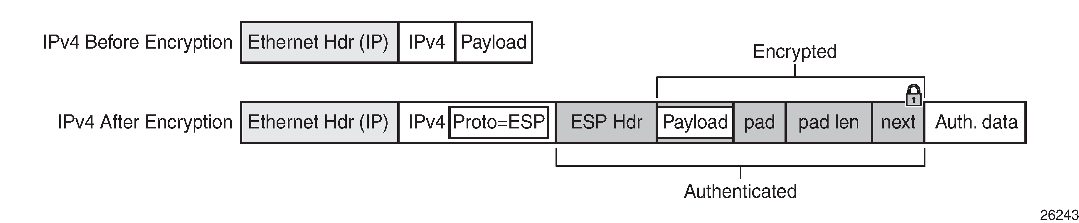
The protocol field in the IP header of an NGE packet is always set to ‟ESP”. Within an NGE domain, the SPI that is included in the ESP header is always an SPI for the key group configured on the router interface. Other fields in the IP header, such as the source and destination addresses, are not altered by NGE router interface encryption. Packets are routed through the NGE domain and decrypted when the packet leaves the NGE domain.
The group keys used on an NGE-enabled router interface provide encryption of broadcast and multicast packets within the GRT. For example, OSPF uses a broadcast address to establish adjacencies, which can be encrypted by NGE without the need to establish point-to-point encryption tunnels. Similarly, multicast packets are also encrypted without point-to-point encryption tunnels.
NGE domains
An NGE domain is a group of nodes and router interfaces forming a network that uses a single key group to create a security domain. NGE domains are created when router interface encryption is enabled on router interfaces that need to participate in the NGE domain. The NSP NFM-P assists users in managing the nodes and interfaces that participate in the NGE domain. See the NSP NFM-P User Guide for more information.
NGE Domain Transit shows various traffic types crossing an NGE domain.
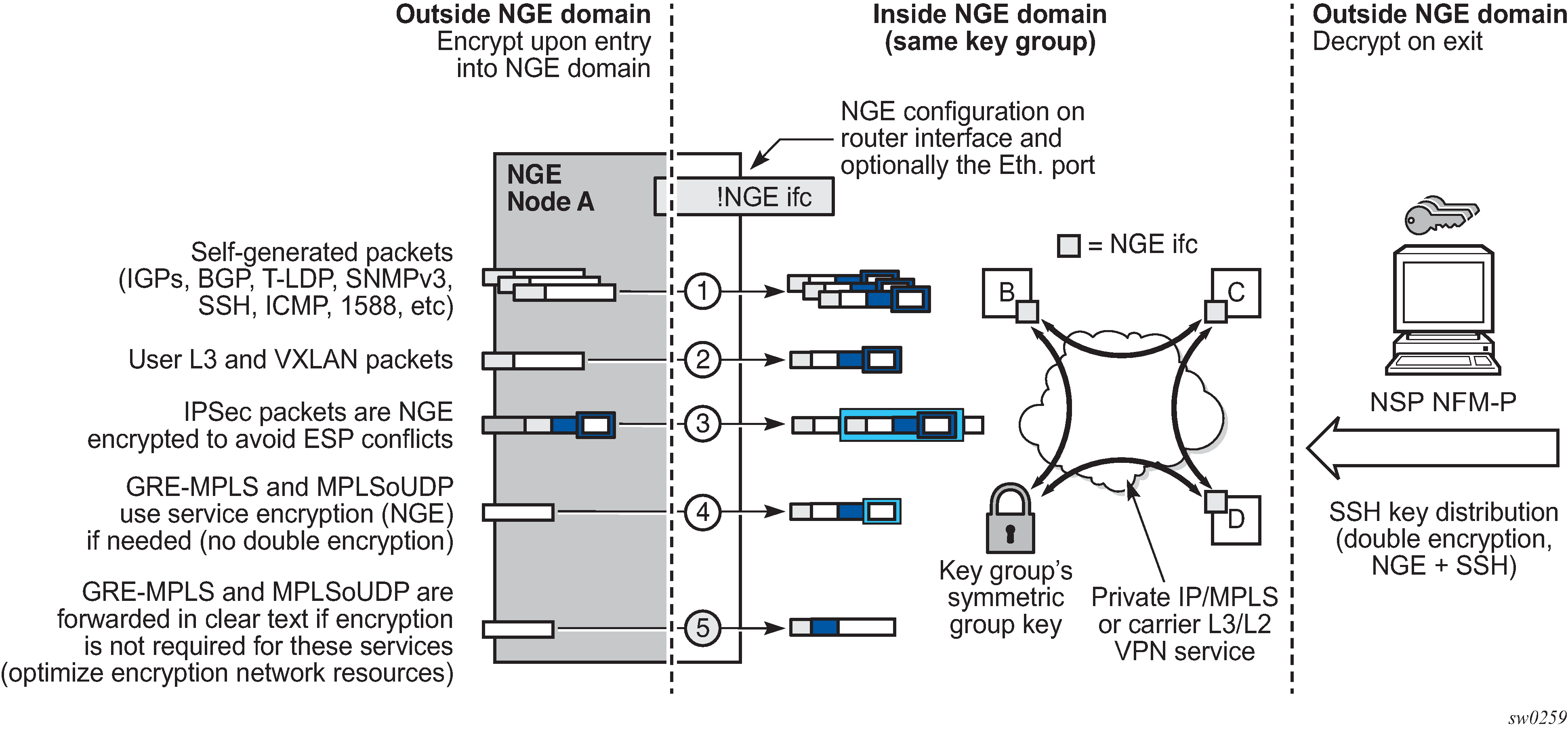
In NGE Domain Transit, nodes A, B, C, and D have router interfaces configured with router interface encryption enabled. Traffic is encrypted when entering the NGE domain using the key group configured on the router interface and is decrypted when exiting the NGE domain. Traffic may traverse multiple hops before exiting the NGE domain, yet decryption only occurs on the final node when the traffic exits the NGE domain.
Various traffic types are supported and encrypted when entering the NGE domain, as illustrated by the following items on node A in NGE Domain Transit:
Item 1: Self-generated packets
These packets, which include all types of control plane and management packets such as OSPF, BGP, LDP, SNMPv3, SSH, ICMP, RSVP-TE, and 1588, are encrypted.
Item 2: User Layer 3 and VXLAN packets
Any Layer 3 user packets that are routed into the NGE domain from an interface outside the NGE domain are encrypted. Any VXLAN packets that are routed into the NGE domain from this NGE node are encrypted.
Item 3: IPsec packets
IPsec packets are NGE-encrypted when entering the NGE domain to ensure that the IPsec packets’ security association information does not conflict with the NGE domain.
GRE-MPLS- or MPLSoUDP-based service traffic consists of Layer 3 packets, and router interface NGE is not applied to these types of packets. Instead, service-level NGE is used for encryption to avoid double-encrypting these packets and impacting throughput and latencies. The two types of GRE-MPLS or MPLSoUDP packets that can enter the NGE domain are illustrated by items 4 and 5 in NGE Domain Transit.
Item 4: GRE-MPLS and MPLSoUDP packets (SDP or VPRN) with service-level NGE enabled
These encrypted packets use the key group that is configured on the service. The services key group may be different from the key group configured on the router interface where the GRE-MPLS or MPLSoUDP packet enters the NGE domain.
Item 5: GRE-MPLS and MPLSoUDP packets (SDP or VPRN) with NGE disabled
These packets are not encrypted and can traverse the NGE domain in clear text. If these packets require encryption, SDP or VPRN encryption must be enabled.
Creating an NGE domain from the NSP NFM-P requires the user to determine the type of NGE domain being managed. This indicates whether NGE gateway nodes are required to manage the NGE domain, and other operational considerations. The two types of NGE domains are:
Private IP/MPLS network NGE domain
One type of NGE domain is a private IP/MPLS network, as shown in Private IP/MPLS network NGE domain.
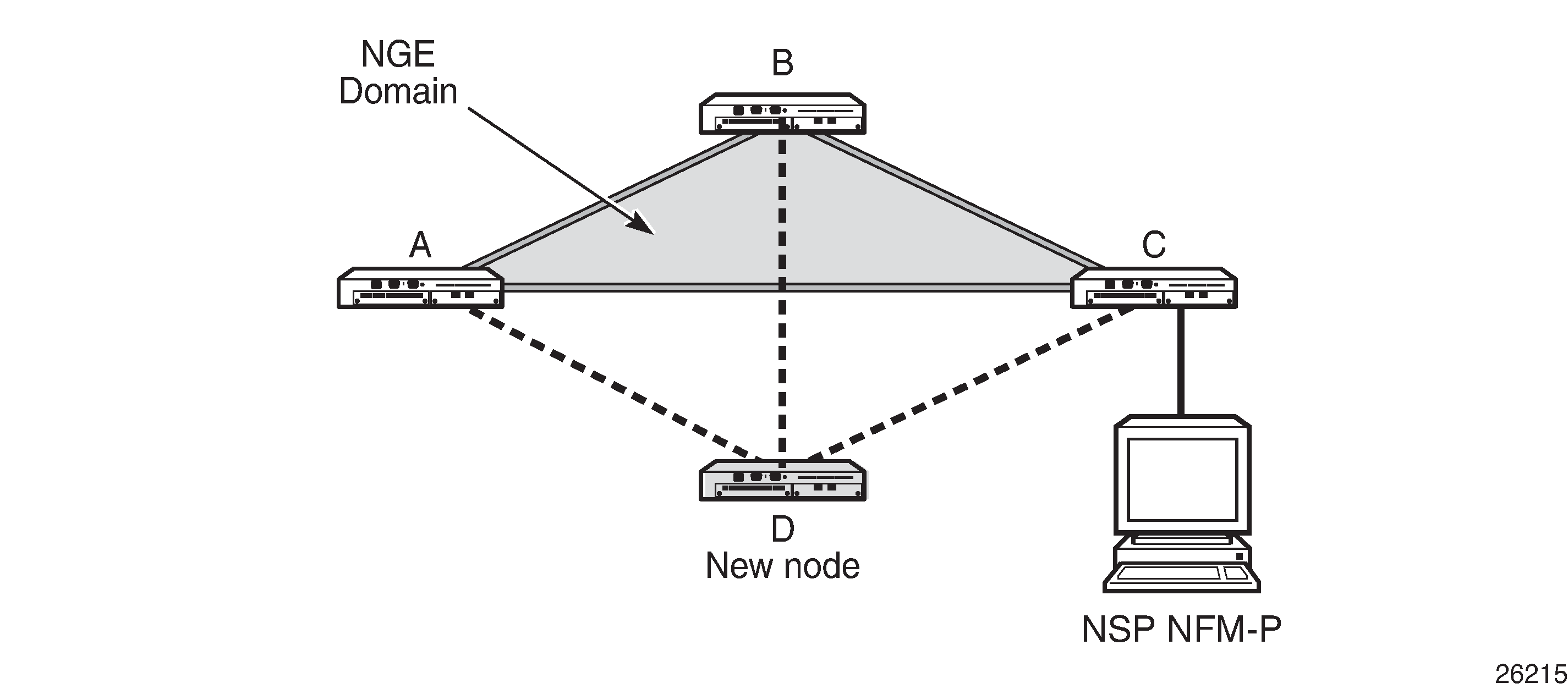
In a private IP/MPLS network NGE domain, all interfaces are owned by the user and there is no intermediary service provider needed to interconnect nodes. Each interface is a point-to-point private link between private nodes. When a new node is added to this type of NGE domain (node D in Private IP/MPLS network NGE domain), the links that connect node D to the existing nodes in the NGE domain (nodes A, B, and C) must be enabled with NGE router interface encryption. Links from the new node to the existing nodes are enabled one at a time. The NSP NFM-P provides tools that simplify adding nodes to the NGE domain and enabling NGE on their associated interfaces. In this type of NGE domain, each interface is a direct link between two nodes and is not used to communicate with multiple nodes over a broadcast medium offered by an intermediary network. Also, there are no NGE gateway nodes required between the NSP NFM-P and new nodes entering the NGE domain.
Private over intermediary network NGE domain
The other type of NGE domain is a private IP/MPLS network that traverses an intermediary network NGE domain; the intermediary network is used to interconnect nodes in the NGE domain using a multipoint-to-multipoint service. The intermediary network is typically a service provider network that provides a private IP VPN service or a private VPLS service used to interconnect a private network that does not mimic point-to-point links as described in the Private IP/MPLS network NGE domain section.
This type of NGE domain is shown in Private over intermediary network NGE domain.
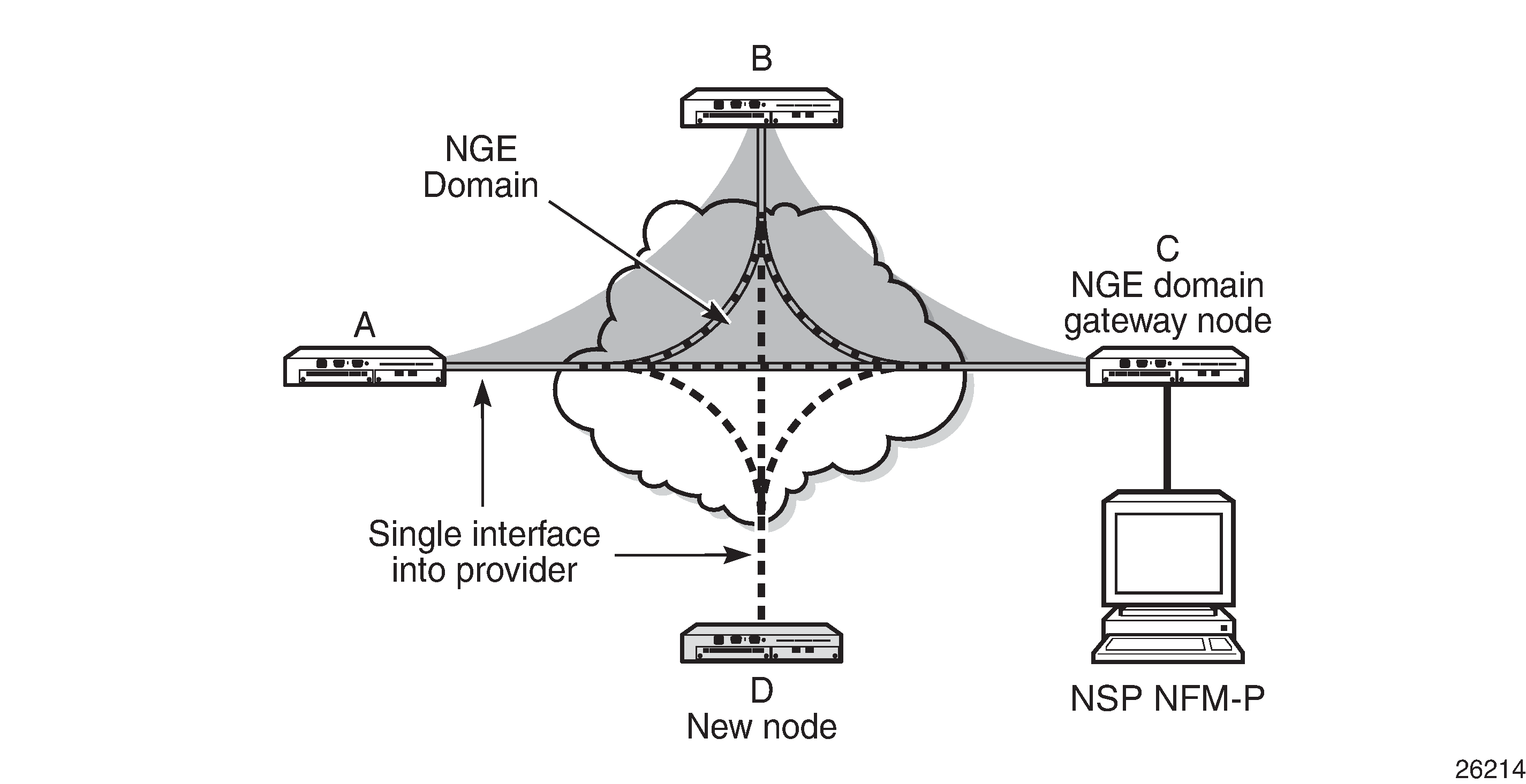
Private over intermediary network NGE domains have nodes with links that connect to a service provider network where a single link can communicate with multiple nodes over a Layer 3 service such as a VPRN. In Private over intermediary network NGE domain, node A has NGE enabled on its interface with the service provider and uses that single interface to communicate with nodes B and C, and eventually with node D when node D has been added to the NGE domain. This type of NGE domain requires the recognition of NGE gateway nodes that allow the NSP NFM-P to reach new nodes that enter the domain. Node C is designated as a gateway node.
When node D is added to the NGE domain, it must first have the NGE domain key group downloaded to it from the NSP NFM-P. The NSP NFM-P creates an NGE exception ACL on the gateway node, C, to allow communication with node D using SNMPv3 and SSH through the NGE domain. After the key group is downloaded, the NSP NFM-P enables router interface encryption on node D’s interface with the service provider and node D is now able to participate in the NGE domain. The NSP NFM-P automatically removes the IP exception ACL from node C when node D enters the NGE domain.
See Router interface NGE domain concepts for more information.
Router interface NGE domain concepts
An NGE domain is a group of nodes whose router interfaces in the base routing context (GRT) are enabled for router interface NGE. An interface without router interface NGE enabled is considered to be outside the NGE domain. NGE domains use only one key group when the domain is created; however, two key groups may be active at when if some links within the NGE domain are in transition from one key group to the other.
Inside and outside NGE domains illustrates the NGE domain concept. Inside and outside NGE domains configuration scenarios describes the three configuration scenarios inside the NGE domain.
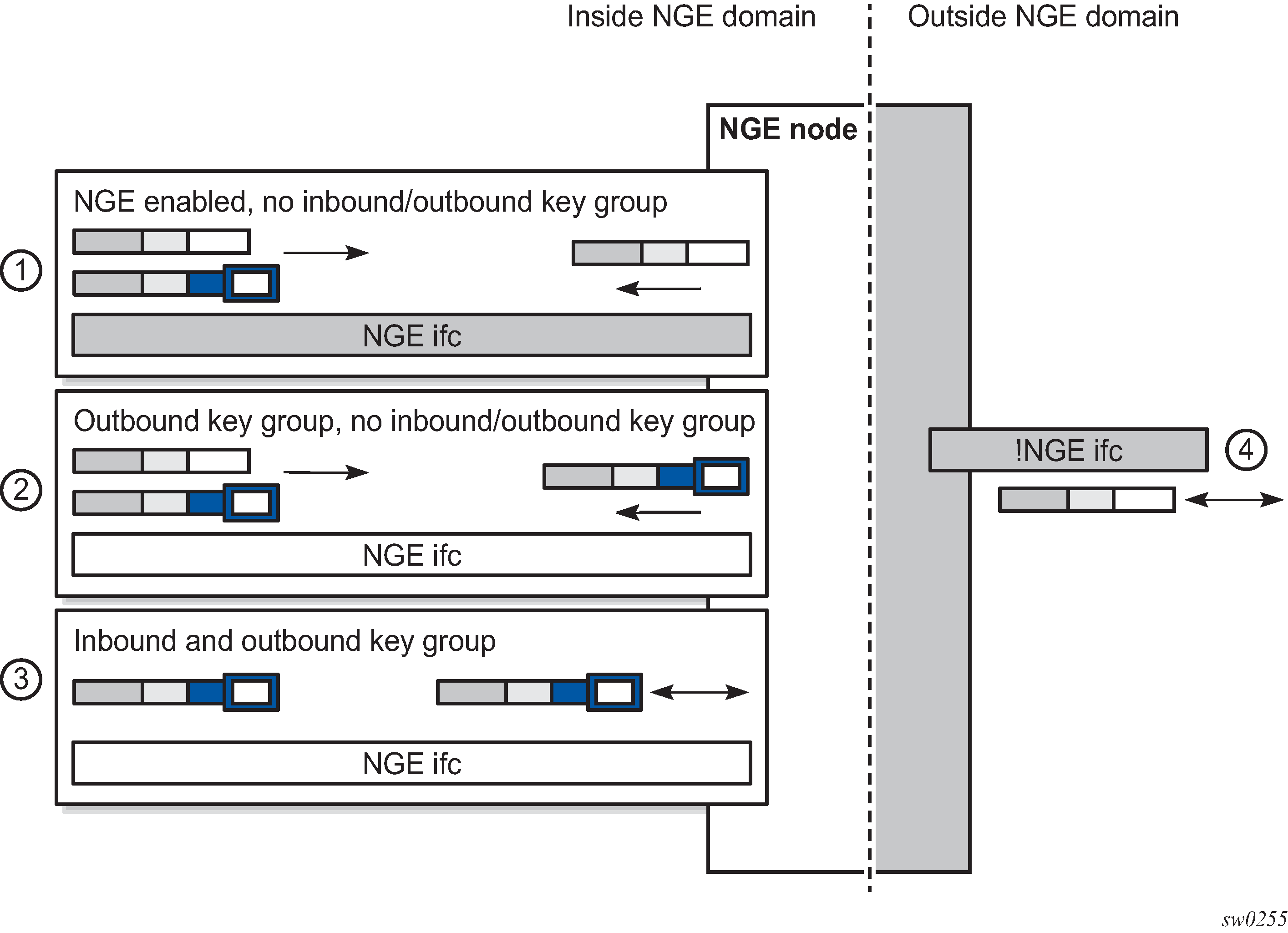
|
Key |
Description |
|---|---|
|
1 |
NGE enabled, no inbound/outbound key group Outbound packets are sent without encrypting; inbound packets can be NGE-encrypted or clear text |
|
2 |
Outbound key group, no inbound key group Outbound packets are encrypted using the interface key group if not already encrypted; inbound packets can be NGE-encrypted or clear text |
|
3 |
Inbound and outbound key group Outbound packets are encrypted using the interface key group if not already encrypted; inbound packets must be encrypted using the interface key group keys |
|
4 |
Outside the NGE domain, the interface is not configured for NGE; any ESP packets are IPsec packets |
A router interface is considered to be inside the NGE domain when it has been configured with group-encryption on the interface. When group-encryption is configured on the interface, the router can receive unencrypted packets or NGE-encrypted packets from any configured key group on the router, but any other type of IPsec-formatted packet is not allowed. If an IPsec-formatted packet is received on an interface that has group-encryption enabled, it does not pass NGE authentication and is dropped. Therefore, IPsec packets cannot exist within the NGE domain without first being converted to NGE packets. This conversion requirement delineates the boundary of the NGE domain and other IPsec services.
When NGE router interface encryption is enabled and only an outbound key group is configured, the interface can receive unencrypted packets or NGE-encrypted packets from any configured key group on the router. All outbound packets are encrypted using the outbound key group if the packet was not already encrypted further upstream in the network.
When NGE router interface encryption has been configured with both an inbound and outbound key group, only NGE packets encrypted with the key group security association can be sent and received over the interface.
When there is no NGE router interface encryption, the interface is considered outside the NGE domain where NGE is not applied.
See the ‟NGE Packet Overhead and MTU Considerations” section in the 7705 SAR Gen 2 Services Overview Guide for MTU information related to enabling NGE on a router interface.
GRE-MPLS and MPLSoUDP packets inside the NGE domain
NGE router interface encryption is never applied to GRE-MPLS or MPLSoUDP packets, for example:
GRE with the GRE protocol ID set to MPLS Unicast (0x8847) or Multicast (0x8848)
UDP packets with destination port = 6635)
GRE-MPLS and MPLSoUDP packets that enter the NGE domain or transit the NGE domain are forwarded as is.
Because these GRE-MPLS and MPLSoUDP packets provide transport for MPLS-based services, they already use the NGE services-based encryption techniques for MPLS, such as SDP or VPRN-based encryption. To avoid double encryption, the packets are left in cleartext when entering an NGE domain or crossing intermediate nodes in the NGE domain, and are forwarded as needed when exiting an NGE domain.
EVPN-VXLAN tunnels and services
NGE router interface encryption does not differentiate between EVPN-VXLAN tunnels and other L3 traffic, and therefore encrypts all EVPN-VXLAN traffic that egresses the node.
For received encrypted EVPN-VXLAN packets, if the VXLAN tunnel terminates on the node (that is, the destination IP is for a VTEP on this node), then the NGE packet is decrypted and the EVPN-VXLAN traffic is processed as if NGE encryption never took place.
Router encryption exceptions using ACLs
In some cases, Layer 3 packets may need to cross the NGE domain in clear text, such as when an NGE-enabled router needs to peer with a non-NGE-capable router to exchange routing information. This can be accomplished by using a router interface NGE exception filter applied on the router interface for the required direction, inbound or outbound.
Router interface NGE exception filter example shows the use of a router interface NGE exception filter.
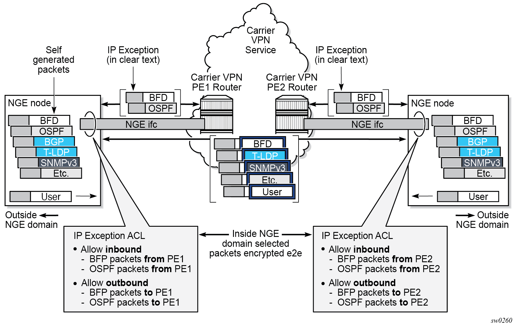
The inbound or outbound exception filter is used to allow specific packet flows through the NGE domain in clear text, where there is an explicit inbound and outbound key group configured on the interface. The behavior of the exception filter for each router interface configuration is as follows:
NGE enabled, no inbound or outbound key group
In this scenario, the router does not encrypt outbound traffic, and so the outbound exception filter is not applied. The router can still receive inbound NGE packets, so the exception filter is applied to inbound packets. If the filter detects a match, clear text packets can be received and forwarded by the router.
Outbound key group, no inbound key group
The outbound exception filter is applied to outbound traffic, and packets that match the filter are not encrypted on egress. The router can receive inbound NGE packets without an inbound key group set and applies the exception filter to inbound packets. If the filter detects a match, clear text packets can be received and forwarded by the router.
Inbound and outbound key group
The inbound and outbound exception filters are applied, and any packets that match are passed in clear text.
IPsec packets crossing an NGE domain
IPsec packets can cross the NGE domain because they are still considered Layer 3 packets. To avoid confusion between the security association used in an IPsec packet and the one used in a router interface NGE packet, the router always applies NGE to any IPsec packet that traverses the NGE domain.
IPsec packets that originate from a router within the NGE domain are not allowed to enter the NGE domain. The only exception to this restriction is OSPFv3 packets.
IPsec packets transiting an NGE domain shows how IPsec packets can transit an NGE domain.
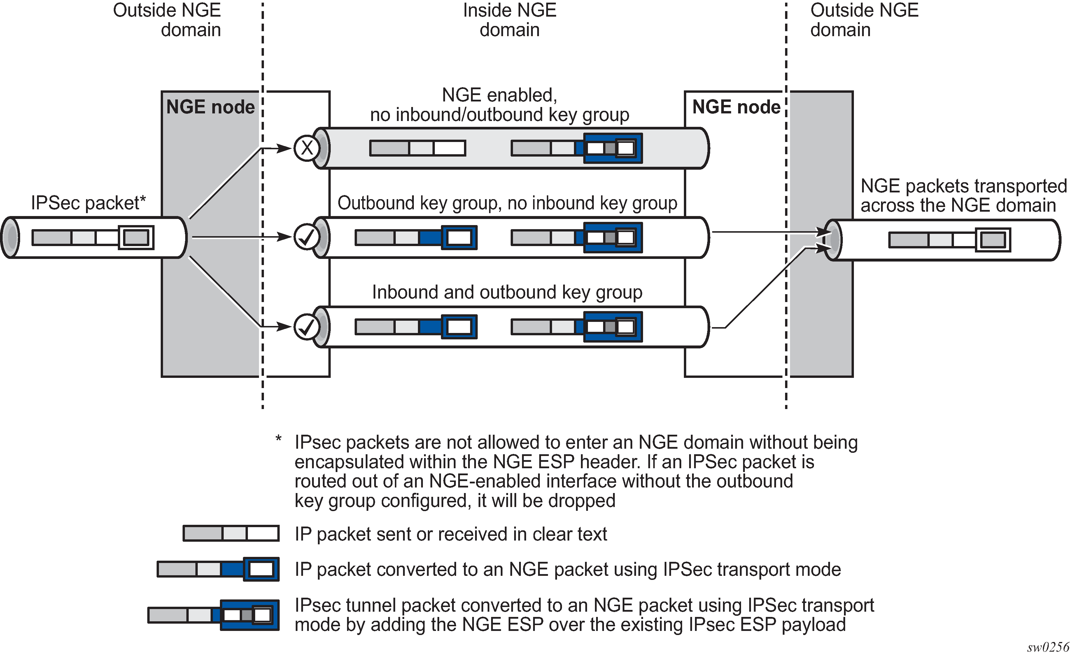
An IPsec packet enters the router from outside the NGE domain. When the router determines that the egress interface to route the packet is inside an NGE domain, it selects an NGE router interface with one of the following configurations.
NGE enabled with no inbound or outbound key group configured
This link cannot forward the IPsec packet without adding the NGE ESP, but because nothing is configured for the outbound key group, the packet must be dropped.
NGE enabled with outbound key group configured and no inbound key group configured — the packet originates outside the NGE domain, so the router adds an ESP header over the existing ESP and encrypts the payload using the NGE domain keys for the configured outbound key group.
NGE enabled with both inbound and outbound key groups configured — the packet originates outside the NGE domain, so the router adds an ESP header over the existing ESP and encrypts the payload using the NGE domain keys for the configured outbound key group.
OSPFv3 IPsec support also uses IPsec transport mode packets. These packets originate from the CPM, which is considered outside the NGE domain; however, the above rules for encapsulating the packets with an NGE ESP apply and allow these packets to successfully transit the NGE domain.
Multicast packets traversing the NGE domain
Multicast packets that traverse an NGE domain can be categorized into two main scenarios:
Scenario 1
Multicast packets that ingress the router on an interface that is outside the NGE domain. These packets can egress a variety of interfaces that are either inside or outside the NGE domain.
Scenario 2
Multicast packets that ingress the router on an interface that is inside the NGE domain. These packets can egress a variety of interfaces that are either inside or outside the NGE domain. This scenario has two cases:
Scenario 2a
The ingress multicast packet is not yet NGE-encrypted.
Scenario 2b
The ingress multicast packet is NGE-encrypted.
Processing multicast packets shows these scenarios.
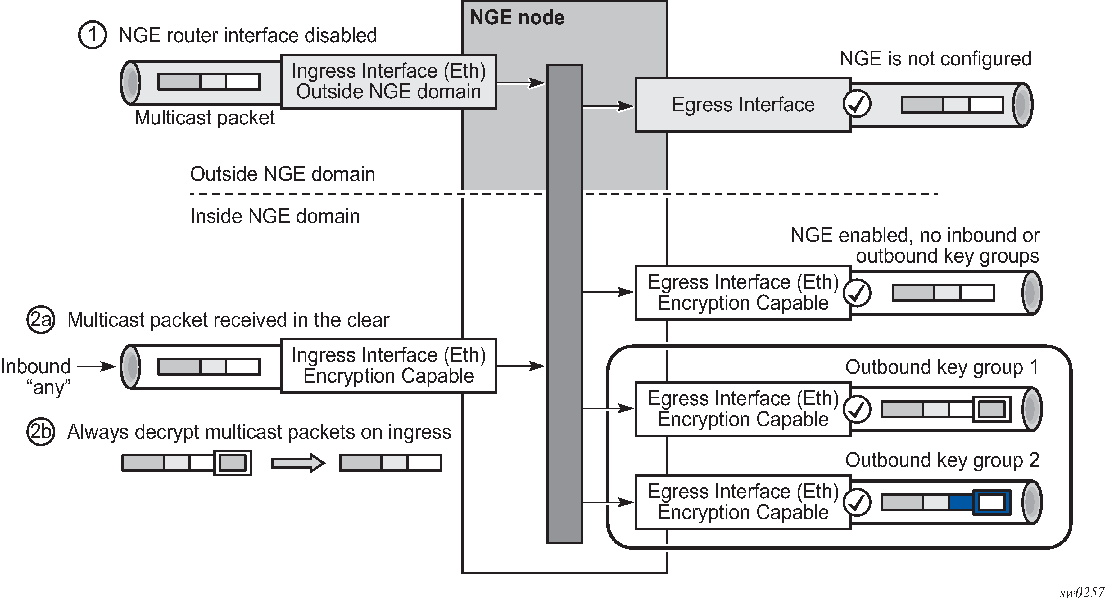
Multicast packets received from outside the NGE domain (Scenario 1) are processed similarly to multicast packets received from inside the NGE domain (Scenarios 2a and 2b).
The processing rule is that multicast packets are always forwarded as clear text over the fabric. This means that for Scenario 2b, when a multicast packet is received on an encryption-capable interface and is NGE-encrypted, the packet is always decrypted first so that it can be processed in the same way as packets in Scenarios 1 and 2a.
On egress, the following scenarios apply:
Egressing an interface outside the NGE domain
Packets are processed in the same way as any multicast packets forwarded out a non-NGE interface.
Egressing an NGE router interface and no inbound or outbound key group is configured
The router forwards these packets out from the egress interface without encrypting them because there is no outbound key group configured. This behavior also applies to unicast packets in the same scenario.
egressing an NGE router interface with the outbound key group configured — the router encrypts the multicast packet using the SPI keys of the outgoing SA configured in the key group. This behavior also applies to unicast packets in the same scenario.
Assigning key groups to router interfaces
Assigning key groups to router interfaces involves the following three steps:
Step1 is required so that the router can initialize and differentiate the interface for NGE traffic before accepting or sending NGE packets. This assigns the interface to an NGE domain.
Assigning key groups to a router interface in steps 2 and 3 is similar to assigning key groups to SDPs or VPRN-based services. An outbound key group cannot be configured for a router interface without first enabling the group-encryption command.
When group-encryption is enabled and no inbound key group is configured, the router accepts NGE Layer 3 packets that were encrypted using keys from any security association configured in any key group on the system. If the packet specifies a security association that is not configured in any key group on the node, the packet is dropped.
The outbound key group references the key group to use when traffic egresses the router on the router interface. The inbound key group is used to make sure ingress traffic is using the correct key group on the router interface. If ingress traffic is not using the correct key group, the router counts these packets as errors.
-
Enable NGE with the group-encryption command.
-
Configure the outbound key group.
-
Configure the inbound key group.
NGE and BFD support
When NGE is enabled on a router interface, BFD packets that originate from the network processor on the adapter card or from the system are encrypted in the same way as BFD packets that are generated by the CPM.
NGE and ACL interactions
When NGE is enabled on a router interface, the ACL function is applied as follows:
on ingress
Normal ACLs are applied to traffic received on the interface that could be either NGE-encrypted or clear text. For NGE-encrypted packets, this implies that only the source, destination, and IP options are available to filter on ingress, as the protocol is ESP, and the packet is encrypted. If an IP exception ACL is also configured on the interface, the IP exception ACL is applied first to allow any clear text packets to ingress as needed. After the IP exception ACL is applied and if another filter or ACL is configured on the interface, the other filter processes the remaining packet stream (NGE-encrypted and IP exception ACL packets), and other ACL functions such as PBR or Layer 4 information filtering could be applied to any clear text packets that passed the exception ACL.
on egress
ACLs are applied to packets before they are NGE-encrypted as per normal operation without NGE enabled.
Router interface NGE and ICMP interactions over the NGE domain
Typically, ICMP works as expected over an NGE domain when all routers participating in the NGE domain are NGE-capable; this includes running an NGE domain over a private IP/MPLS network. When an ICMP message is required, the NGE packet is decrypted first, and the original packet is restored to create a detailed ICMP message using the original packet’s header information.
When the NGE domain crosses a Layer 3 service provider, or crosses over routers that are not NGE-aware, it is not possible to create a detailed ICMP message using the original packet’s information, as the NGE packet protocol is always set to ESP. Furthermore, the NGE router that receives these ICMP messages drops them because the messages are not NGE-encrypted.
The combination of dropping ICMP messages at the NGE border node and the missing unencrypted packet details in the ICMP information can cause problems with diagnosing network issues.
To help with diagnosing network issues, additional statistics are available on the interface to show whether ICMP messages are being returned from a foreign node. The following statistics are included in the group encryption NGE statistics for an interface:
Group Enc Rx ICMP DestUnRch Pkts
Group Enc Rx ICMP TimeExc Pkts
Group Enc Rx ICMP Other Pkts
These statistics are used when clear text ICMP messages are received on an NGE router interface. The Invalid ESP statistics are not used in this situation even though the packet does not have a correct NGE ESP header. If there is no ingress exception ACL configured on the interface to allow the ICMP messages to be forwarded, the messages are counted and dropped.
If more information is required for these ICMP messages, such as source or destination address information, a second ICMP filter can be configured on the interface to allow logging of the ICMP messages. If the original packet information is also required, an egress exception ACL can be configured with the respective source or destination address information, or other criteria, to allow the original packet to enter the NGE domain in clear text and determine which flows are causing the ICMP failures.
1588v2 encryption with NGE
If a router interface is enabled for encryption and Layer 3 1588v2 packets are sent, they are encrypted using NGE. This means that if port timestamping is enabled on a router interface with NGE, the port timestamp is applied to the Layer 3 1588v2 packet using software-based timestamping instead of hardware-based timestamping, and consequently, timing accuracy may degrade. The exact level of timing or synchronization degradation is dependent on many factors, and testing is recommended to measure any impact.
If there is a need to support Layer 3 1588v2 with better accuracy for frequency or better time using port timestamping, an NGE exception ACL is required to keep the Layer 3 1588v2 packets in clear text. The exception ACL must enable UDP packets with destination port 319 to be sent in clear text.
Process overview
The following items are components to configure basic router command options:
interface
A logical IP routing interface. When created, attributes like an IP address, port, link aggregation group, or the system can be associated with the IP interface.
address
The address associates the device system name with the IP system address. An IP address must be assigned to each IP interface.
system interface
This creates an association between the logical IP interface and the system (loopback) address. The system interface address is the circuitless address (loopback) and is used by default as the router ID for protocols such as OSPF and BGP.
router ID
(Optional) The router ID specifies the router IP address.
autonomous system
(Optional) AS is a collection of networks that are subdivided into smaller, more manageable areas.
-
confederation
(Optional) This option creates confederation-autonomous systems within an AS to reduce the number of iBGP sessions required within an AS.
Configuration notes
The following information describes router configuration requirements:
A system interface and associated IP address must be specified.
Boot options file (BOF) options must be configured before configuring router command options.
Confederations can be configured before protocol connections (such as BGP) and peering command options are configured.
Configuring an IP router with CLI
This following sections provide information to configure an IP router.
IP router configuration overview
In a Nokia router, an interface is a logical named entity. An interface is created by specifying an interface name under the configure router context. This is the global router configuration context where objects like static routes are defined. An IP interface name can be up to 32 alphanumeric characters, must start with a letter, and is case-sensitive; for example, the interface name ‟1.1.1.1” is not allowed, but ‟int-1.1.1.1” is allowed.
If the interface name already exists, the router changes the context to maintain that IP interface. If the interface name already exists within another service ID or is an IP interface defined within the configure router commands, an error occurs and the context does not change to that IP interface.
To create an interface, the following basic configuration tasks must be performed:
- Assign a name to the interface.
- Associate an IP address with the interface.
- Associate the interface with a network interface or the system interface.
- Configure the appropriate routing protocols.
A system interface and network interface are configured.
System interface
The system interface is associated with a network entity (such as a specific Nokia router), not a specific interface. The system interface is also referred to as the loopback address. The system interface is associated during the configuration of the following entities:
the termination point of service tunnels
the hops when configuring MPLS paths and LSPs
the addresses on a target router for BGP and LDP peering
The system interface is used to preserve connectivity (when routing reconvergence is possible) when an interface fails or is removed. The system interface is used as the router identifier. A system interface must have an IP address with a 32-bit subnet mask.
Network interface
A network interface can be configured on one of the following entities:
-
physical or logical port
-
SONET/SDH channel
Basic configuration
See each specific chapter for specific routing protocol information and command syntax to configure protocols such as IS-IS and BGP.
The most basic router configuration must have the following:
system name
system address
The following example shows the 7705 SAR Gen 2 router configuration.
MD-CLI
[ex:/configure router "Base"]
A:admin@node-2# info
    autonomous-system 100
    router-id 10.10.10.103
    confederation {
        confed-as-num 1000
        members 100 { }
        members 200 { }
        members 300 { }
    }
...
    interface "system" {
        ipv4 {
            primary {
                address 10.10.10.103
                prefix-length 32
            }
        }
    }
    interface "to-104" {
        port 1/1/1
        ipv4 {
            primary {
                address 10.0.0.103
                prefix-length 24
            }
        }
    }
...
    isis 0 {
        loopfree-alternate {
        }
    }
classic CLI
A:node-2>config# info
. . .
#------------------------------------------
# Router Configuration
#------------------------------------------
    router
        interface "system"
            address 10.10.10.103/32
        exit
        interface "to-104"
            address 10.0.0.103/24
            port 1/1/1
            exit
        exit
        autonomous-system 100
        confederation 1000 members 100 200 300
   router-id 10.10.10.103
...
    exit
    isis
    exit
...
#------------------------------------------
Common configuration tasks
This section describes the basic system configuration tasks.
Configuring a system name
Use the system command to configure a name for the device. The name is used in the prompt string. Only one system name can be configured. If multiple system names are configured, the last one configured overwrites the previous entry.
If special characters are included in the system name string (for example, spaces, ‟#”, or ‟?”), the entire string must be enclosed in double quotes. Use the following syntax to configure the system name.
MD-CLI
[ex:/configure system]
A:admin@node-2# info
    name "node-2"
    location "Mt.View, CA, NE corner of FERG 1 Building"
    coordinates "37.390, -122.05500 degrees lat."
classic CLI
A:node-2>config>system# info
#------------------------------------------
# System Configuration
#------------------------------------------
        name "node-2"
        location "Mt.View, CA, NE corner of FERG 1 Building"
        coordinates "37.390, -122.05500 degrees lat."
Configuring interfaces
The following command sequences create a system and a logical IP interface. The system interface assigns an IP address to the interface, then associates the IP interface with a physical port. The logical interface can associate attributes like an IP address or port.
The system interface cannot be deleted.
Configuring a system interface
Use the following command to configure a system interface.
configure router interface
Configuring a network interface
Use the commands in the following context to configure a network interface.
configure router interfaceThe following example shows network interface configuration information.
MD-CLI
[ex:/configure router "Base"]
A:admin@node-2# info
...
interface "system" {
        ipv4 {
            primary {
                address 10.10.0.4/32
                prefix-length 32
            }
        }
     }
interface "to-ALA-2" {
        port 1/1/1
        egress {
            filter {
                ip "10"
            }
        }
    }
classic CLI
A:node-2>config>router# info
#------------------------------------------
# IP Configuration
#------------------------------------------
        interface "system"
            address 10.10.0.4/32
        exit
        interface "to-ALA-2"
            address 10.10.24.4/24
            port 1/1/1
            egress
                filter ip 10
            exit
        exit
...
#------------------------------------------
Use the following command to enable CPU protection.
configure router interface cpu-protectionUse the commands in the following context to configure CPU protection policies.
configure system security cpu-protectionFor more information, see the 7705 SAR Gen 2 System Management Guide.
Assigning a key group to a router interface
The following example shows key group configuration for a router interface.
classic CLI
A:node-2>config>router# info
----------------------------------------------
...
        interface demo
            group-encryption
                encryption-keygroup 6 direction inbound
                encryption-keygroup 6 direction outbound
                exit
            no shutdown
            exit
        exit
...
----------------------------------------------
Configuring IPv6
Default configuration when IPv6 is enabled on an interface (MD-CLI)
[ex:/configure router "Base" interface "demo"]
A:admin@node-2# info
    admin-state enable
    port 1/2/37
    ipv6 {
        icmp6 {
            packet-too-big {
                number 100
                seconds 10
            }
            param-problem {
                number 100
                seconds 10
            }
            redirects {
                number 100
                seconds 10
            }
            time-exceeded {
                number 100
                seconds 10
            }
            unreachables {
                number 100
                seconds 10
            }
        }
    }
Default configuration when IPv6 is enabled on an interface (classic CLI)
A:node-2>config>router>if# info
----------------------------------------------
            port 1/2/37
            ipv6
            exit
            no shutdown

A:node-2>config>router>if>ipv6# info detail
----------------------------------------------
                icmp6
                    packet-too-big 100 10
                    param-problem 100 10
                    redirects 100 10
                    time-exceeded 100 10
                    unreachables 100 10
                exit
Use the commands in the following context to configure IPv6 on a router interface that you want to configure differently from the default configuration.
configure router interface ipv6 icmp6Configuration of IPv6 on a router interface (MD-CLI)
[ex:/configure router "Base" interface "demo"]
A:admin@node-2# info
    port 1/2/3
    ipv4 {
        primary {
            address 10.11.10.1
            prefix-length 24
        }
    }
    ipv6 {
        address 2001:db8::1 {
            prefix-length 24
        }
    }
Configuration of IPv6 on a router interface (classic CLI)
A:node-2>config>router>if# info
----------------------------------------------
            address 10.11.10.1/24
            port 1/2/37
            ipv6
                address 2001:db8::1/24
            exit
----------------------------------------------
Configuring IPv6 over IPv4
The following sections provide several examples of the features that must be configured (tunnel ingress and egress node) to implement IPv6 over IPv4 relay services.
Tunnel ingress node
The following example shows the configuration of the interface through which the IPv6 over IPv4 traffic leaves the node. This must be configured on a network interface.
MD-CLI
[ex:/configure router "Base"]
A:admin@node-2# info
...
    static-routes {
        route 3ffe::c8c8:c802/128 route-type unicast {
            indirect 10.200.200.2 {
            }
        }
    }
classic CLI
A:node-2>config>router# info
...
#--------------------------------------------------
echo "Static Route Configuration"
#--------------------------------------------------
        static-route-entry 3ffe::c8c8:c802/128
            indirect 10.200.200.2
                shutdown
                tunnel-next-hop
                    resolution disabled
                exit
            exit
        exit
----------------------------------------------
The following example shows the configuration of the network interface.
MD-CLI
[ex:/configure router "Base"]
A:admin@node-2# info
    interface "ip-1.1.1.1" {
        port 1/1/1
        ipv4 {
            primary {
                address 10.1.1.1
                prefix-length 30
            }
        }
    }
classic CLI
A:node-2>config>router# info
----------------------------------------------
...
        interface "ip-1.1.1.1"
            address 10.1.1.1/30
            port 1/1/1
          exit
...
----------------------------------------------
Both the IPv4 and IPv6 system addresses must be configured. The following example shows the configuration of interface information.
MD-CLI
[ex:/configure router "Base"]
A:admin@node-2# info
...
    interface "system" {
        ipv4 {
            primary {
                address 10.0.113.1
                prefix-length 32
            }
        }
        ipv6 {
            address 3ffe::c8c8:c801 {
                prefix-length 128
            }
        }
    }
classic CLI
A:node-2>config>router# info
----------------------------------------------
...
        interface "system"
            address 10.0.113.1/32
            ipv6
                address 3ffe::c8c8:c801/128
            exit
        exit
...
----------------------------------------------
Learning the tunnel endpoint IPv4 system address
The following example shows the OSPF configuration to learn the IPv4 system address of the tunnel endpoint.
MD-CLI
[ex:/configure router "Base"]
A:admin@node-2# info
    ospf 0 {
        area 0.0.0.0 {
            interface "ip-1.1.1.1" {
            }
            interface "system" {
            }
        }
    }
classic CLI
A:node-2>config>router# info
----------------------------------------------
...
        ospf
            area 0.0.0.0
                interface "system"
                exit
                interface "ip-1.1.1.1"
                exit
            exit
        exit
----------------------------------------------
Configuring an IPv4 BGP peer
The following example shows the configuration of an IPv4 BGP peer with (IPv4 and) IPv6 protocol families.
MD-CLI
[ex:/configure router "Base"]
A:admin@node-2# info
     bgp {
        router-id 203.0.113.1
        }
        export {
            policy ["ospf3"]
        }
        group "main" {
            type internal
            family {
                ipv4 true
                ipv6 true
            }
        }
        neighbor "203.0.113.2" {
            group "main"
            peer-as 1
            local-as {
                as-number 1
            }
        }
    }
classic CLI
A:node-2>config>router# info
----------------------------------------------
...
        bgp
            export "ospf3"
            router-id 203.0.113.1
            group "main"
                family ipv4 ipv6
                type internal
                neighbor 203.0.113.2
                    local-as 1
                    peer-as 1
                exit
            exit
        exit
...
----------------------------------------------
IPv6 over IPv4 tunnel configuration example
The IPv6 address is the next-hop as it is received through BGP. The IPv4 address is the system address of the tunnel's endpoint.
See Configuring an IPv4 BGP peer for an example that shows the configuration of a policy to export IPv6 routes into BGP.
The following example shows an IPv6 over IPv4 tunnel configuration.
MD-CLI
[ex:/configure policy-options]
A:admin@node-2# info
    policy-statement "ospf3" {
        description "Plcy Stmnt For 'From ospf3 To bgp'"
        entry 10 {
            description "Entry From Protocol ospf3 To bgp"
            from {
                protocol {
                    name [ospf3]
                }
            }
            to {
                protocol {
                    name [bgp]
                }
            }
            action {
                action-type accept
            }
        }
    }
classic CLI
A:node-2>config>router# info
----------------------------------------------
...
        policy-options
            policy-statement "ospf3"
                description "Plcy Stmnt For 'From ospf3 To bgp'"
                entry 10
                    description "Entry From Protocol ospf3 To bgp"
                    from
                        protocol ospf3
                    exit
                    to
                        protocol bgp
                    exit
                    action accept
                    exit
                exit
            exit
        exit
...
----------------------------------------------
Tunnel egress node
The following example shows the configuration of the interface through which the IPv6 over IPv4 traffic leaves the node. It must be configured on a network interface. Both the IPv4 and IPv6 system addresses must be configured.
MD-CLI
[ex:/configure router "Base"]
A:admin@node-2# info
...
  static-routes {
        route 3ffe::c8c8:c801/128 route-type unicast {
            indirect 10.0.113.1 {
                }
        }
classic CLI
A:node-2>config>router# info
#--------------------------------------------------
"Static Route Configuration"
#--------------------------------------------------
        static-route-entry 3ffe::c8c8:c801/128
            indirect 10.0.113.1
...
                exit
            exit
        exit
The following example shows the network interface configuration with both IPv4 and IPv6 addresses configured.
MD-CLI
[ex:/configure router "Base"]
A:admin@node-2# info
    interface "ip-1.1.1.2" {
        port 1/1/1
        ipv4 {
            primary {
                address 10.1.1.2
                prefix-length 30
            }
        }
    }
    interface "system" {
        ipv4 {
            primary {
                address 10.0.113.2
                prefix-length 32
            }
        }
        ipv6 {
            address 3ffe::c8c8:c802 {
                prefix-length 128
            }
        }
    }
classic CLI
A:node-2>config>router# info
----------------------------------------------
...
        interface "ip-1.1.1.2"
            address 10.1.1.2/30
            port 1/1/1
        exit
        interface "system"
            address 10.0.113.2/32
            ipv6
                address 3ffe::c8c8:c802/128
            exit
        exit
----------------------------------------------
Learning the tunnel endpoint IPv4 system address
The following example shows the configuration of the OSPF configuration to learn the IPv4 system address of the tunnel endpoint.
MD-CLI
[ex:/configure router "Base"]
A:admin@node-2# info
...
ospf 0 {
        area 0.0.0.0 {
            interface "ip-1.1.1.2" {
            }
            interface "system" {
            }
        }
    }
classic CLI
A:node-2>config>router# info
----------------------------------------------
...
        ospf
            area 0.0.0.0
                interface "system"
                exit
                interface "ip-1.1.1.2"
                exit
            exit
        exit
----------------------------------------------
Configuring an IPv4 BGP peer
The following example shows the configuration an IPv4 BGP peer with (IPv4 and) IPv6 protocol families.
MD-CLI
[ex:/configure router "Base"]
A:admin@node-2# info
...
    bgp {
        router-id 203.0.113.2
        export {
            policy ["ospf3"]
        }
        group "main" {
            type internal
            family {
                ipv4 true
                ipv6 true
            }
        }
        neighbor "203.0.113.1" {
            group "main"
            peer-as 1
            local-as {
                as-number 1
            }
        }
    }
classic CLI
A:node-2config>router# info
----------------------------------------------
...
        bgp
            export "ospf3"
            router-id 203.0.113.2
            group "main"
                family ipv4 ipv6
                type internal
                neighbor 203.0.113.1
                    local-as 1
                    peer-as 1
                exit
            exit
        exit
...
----------------------------------------------
IPv6 over IPv4 tunnel configuration example
The IPv6 address is the next-hop as it is received through BGP. The IPv4 address is the system address of the tunnel's endpoint.
See Configuring an IPv4 BGP peer for an example of the configuration of a policy to export IPv6 routes into BGP.
The following example shows an IPv6 over IPv4 tunnel configuration.
MD-CLI
[ex:/configure policy-options]
A:admin@node-2# info
    policy-statement "ospf3" {
        description "Plcy Stmnt For 'From ospf3 To bgp'"
        entry 10 {
            description "Entry From Protocol ospf3 To bgp"
            from {
                protocol {
                    name [ospf3]
                }
            }
            to {
                protocol {
                    name [bgp]
                }
            }
            action {
                action-type accept
            }
        }
    }
classic CLI
A:node-2>config>router# info
----------------------------------------------
...
        policy-options
            policy-statement "ospf3"
                description "Plcy Stmnt For 'From ospf3 To bgp'"
                entry 10
                    description "Entry From Protocol ospf3 To bgp"
                    from
                        protocol ospf3
                    exit
                    to
                        protocol bgp
                    exit
                    action accept
                    exit
                exit
            exit
        exit
----------------------------------------------
Router advertisement
To configure the router to originate router advertisement messages on an interface, the interface must be configured under the router-advertisement context and be enabled. All other router advertisement configuration command options are optional.
Use the commands in the following contexts to configure router advertisement:
-
MD-CLI
configure router ipv6 router-advertisement configure service vprn ipv6 router-advertisement -
classic CLI
configure router router-advertisement
configure service vprn router-advertisement
The following example shows a router advertisement configuration.
MD-CLI
[ex:/configure router "Base"]
A:admin@node-2# info
...
    ipv6 {
        router-advertisement {
            interface "n1" {
                admin-state enable
                use-virtual-mac true
                prefix 2001:db8:2::/64 {
                }
                prefix 2001:db8:3::/64 {
                    autonomous true
                    on-link true
                    preferred-lifetime 604800
                    valid-lifetime 2592000
                }
            }
        }
    }
classic CLI
A:node-2>config>router>router-advert# info
----------------------------------------------
            interface "n1"
                prefix 2001:db8:3::/64
                exit
                use-virtual-mac
                no shutdown
            exit
----------------------------------------------
*A:node-2>config>router>router-advert# interface n1
*A:node-2>config>router>router-advert>if# prefix 2001:db8:3::/64
A:node-2>config>router>router-advert>if>prefix# info
----------------------------------------------
                    autonomous
                    on-link
                    preferred-lifetime 604800
                    valid-lifetime 2592000
----------------------------------------------
Configuring IPv6
The following example shows the default configuration when IPv6 is enabled on the interface.
Default IPv6 configuration (MD-CLI)
[ex:/configure router "Base"]
A:admin@node-2# info
    interface "test" {
        port 1/3/37
        ipv6 {
        }
    }
[ex:/configure router "Base" interface "test" ipv6]
A:admin@node-2# info detail
...
    icmp6 {
        packet-too-big {
            admin-state enable
            number 100
            seconds 10
        }
        param-problem {
            admin-state enable
            number 100
            seconds 10
        }
        redirects {
            admin-state enable
            number 100
            seconds 10
        }
        time-exceeded {
            admin-state enable
            number 100
            seconds 10
        }
        unreachables {
            admin-state enable
            number 100
            seconds 10
        }
    }
Default IPv6 configuration (classic CLI)
A:node-2>config>router# info
----------------------------------------------
#--------------------------------------------------
   "IP Configuration"
#--------------------------------------------------
        interface "test"
            port 1/3/37
            ipv6
                exit
            no shutdown
        exit
A:node-2>config>router>if>ipv6$ info detail
----------------------------------------------
                icmp6
                    packet-too-big 100 10
                    param-problem 100 10
                    redirects 100 10
                    time-exceeded 100 10
                    unreachables 100 10
                exit
The following example shows an IPv6 configuration.
IPv6 configuration (MD-CLI)
[ex:/configure router "Base" interface "test"]
A:admin@node-2# info
    port 1/3/37
    ipv4 {
        primary {
            address 10.11.10.1
            prefix-length 24
        }
    }
    ipv6 {
        address 2001:db8::1 {
            prefix-length 24
        }
    }
IPv6 configuration (classic CLI)
A:node-2>config>router>if# info
----------------------------------------------
            address 10.11.10.1/24
            port 1/3/37
            ipv6
                address 2001:db8::1/24
            exit
----------------------------------------------
IPv6 over IPv4 tunnel configuration example
The IPv6 address is the next-hop as it is received through BGP. The IPv4 address is the system address of the tunnel's endpoint.
Use the commands in the following context to export IPv6 routes into BGP.
configure router bgp exportThe following example shows an IPv6 over IPv4 tunnel configuration.
MD-CLI
[ex:/configure policy-options]
A:admin@node-2# info
    policy-statement "ospf3" {
        description "Plcy Stmnt For 'From ospf3 To bgp'"
        entry 10 {
            description "Entry From Protocol ospf3 To bgp"
            from {
                protocol {
                    name [ospf3]
                }
            }
            to {
                protocol {
                    name [bgp]
                }
            }
            action {
                action-type accept
            }
        }
    }
classic CLI
A:node-2>config>router# info
----------------------------------------------
...
        policy-options
            policy-statement "ospf3"
                description "Plcy Stmnt For 'From ospf3 To bgp'"
                entry 10
                    description "Entry From Protocol ospf3 To bgp"
                    from
                        protocol ospf3
                    exit
                    to
                        protocol bgp
                    exit
                    action accept
                    exit
                exit
            exit
        exit
----------------------------------------------
Configuring proxy ARP
To configure proxy ARP, you can configure:
A prefix list. Use the commands in the following context to configure a prefix list:
-
MD-CLI
configure policy-options prefix-list -
classic CLI
configure router policy-options prefix-list
-
A route policy statement and apply the specified prefix list. Use the commands in the following context to configure a route policy statement and apply the specified prefix list:
-
MD-CLI
configure policy-options policy-statement -
classic CLI
configure router policy-options policy-statement-
In the policy statement entry to context, specify the host source address(es) for which ARP requests can or cannot be forwarded to non-local networks, depending on the specified action.
-
In the policy statement entry from context, specify network prefixes that ARP requests to be forwarded or not forwarded depending on the action if a match is found. For more information about route policies, see the 7705 SAR Gen 2 Unicast Routing Protocols Guide.
-
-
-
Apply the policy statement to the proxy ARP configuration. Use the commands in the following context to apply the policy statement to the proxy ARP configuration.
configure router interface
Prefix list and policy statement configuration (MD-CLI)
[ex:/configure]
A:admin@node-2# info
 policy-options {
        prefix-list "prefixlist1" {
            prefix 10.20.30.0/24 type through {
                through-length 32
            }
        }
        policy-statement "ProxyARPpolicy" {
            entry 10 {
                from {
                    prefix-list ["prefixlist1"]
                }
                to {
                    prefix-list ["prefixlist2"]
                }
                action {
                    action-type reject
                }
            }
            default-action {
                action-type accept
            }
        }
    }
Prefix list and policy statement configuration (classic CLI)
A:node-2>config>router>policy-options# info
----------------------------------------------
            prefix-list "prefixlist1"
                    prefix 10.20.30.0/24 through 32
            exit
            prefix-list "prefixlist2"
                    prefix 10.10.10.0/24 through 32
            exit
...
            policy-statement "ProxyARPpolicy"
                entry 10
                    from
                        prefix-list "prefixlist1"
                    exit
                    to
                        prefix-list "prefixlist2"
                    exit
                    action reject
                exit
                default-action accept
                exit
            exit
...
----------------------------------------------
The following example shows a proxy ARP configuration.
Proxy ARP configuration (MD-CLI)
[ex:/configure router "Base" interface "iparptest"]
A:admin@node-2# info
    ipv4 {
        primary {
            address 192.0.2.59
            prefix-length 24
        }
        neighbor-discovery {
            local-proxy-arp true
            proxy-arp-policy ["ProxyARPpolicy"]
        }
    }
Proxy ARP configuration (classic CLI)
A:node-2>config>router>if# info
----------------------------------------------
            address 192.0.2.59/24
            local-proxy-arp
            proxy-arp-policy "ProxyARPpolicy"
            exit
----------------------------------------------
Deriving the router ID
The router ID defaults to the address specified in the system interface command. If the system interface is not configured with an IP address, the router ID inherits the last four bytes of the MAC address.
Use the commands in the following context to configure the router ID manually.
configure routerUse the commands in the following context, on the BGP protocol level, to define a BGP router ID.
configure router bgp router-idIf a new router ID is configured, protocols are not automatically restarted with the new router ID. The next time a protocol is initialized, the new router ID is used. An interim period of time can occur when different protocols use different router IDs. To force the new router ID, issue the shutdown and no shutdown commands for each protocol that uses the router ID, or restart the entire router.
It is possible to configure SR OS to operate with an IPv6 only BOF and no IPv4 system interface address. When configured in this manner, the user must explicitly define IPv4 router IDs for protocols such as OSPF and BGP because there is no mechanism to derive the router ID from an IPv6 system interface address.
The following example shows a router ID configuration.
MD-CLI
[ex:/configure router "Base"]
A:admin@node-2# info
    router-id 10.10.0.4
    interface "system" {
        ipv4 {
            primary {
                address 10.10.0.4
                prefix-length 32
            }
        }
    }
classic CLI
A:node-2config>router# info
#------------------------------------------
# IP Configuration
#------------------------------------------
        interface "system"
            address 10.10.0.4/32
        exit
    . . .
        router-id 10.10.0.4
#------------------------------------------
Configuring a confederation
Configuring a confederation is optional. The AS and confederation topology design should be carefully planned. Autonomous system (AS), confederation, and BGP connection and peering must be explicitly created on each participating router. Identify AS numbers, confederation numbers, and members participating in the confederation.
See the BGP section for CLI syntax and command descriptions.
The following example shows the configuration of the confederation topology in Confederation configuration.
Confederations can be preconfigured before configuring BGP connections and peering.
Each confederation can have up to 15 members.
MD-CLI
[ex:/configure router "Base"]
A:admin@node-2# info
    autonomous-system 100
    router-id 10.10.10.103
    confederation {
        confed-as-num 2002
        members 200 { }
        members 300 { }
        members 400 { }
    }
    interface "system" {
        ipv4 {
            primary {
                address 10.10.10.103
                prefix-length 32
            }
        }
    }
    interface "to-104" {
        port 1/1/1
        ipv4 {
            primary {
                address 10.0.0.103
                prefix-length 24
            }
        }
    }
classic CLI
A:node-2>config>router# info
#------------------------------------------
# IP Configuration
#------------------------------------------
        interface "system"
            address 10.10.10.103/32
        exit
        interface "to-104"
            address 10.0.0.103/24
            port 1/1/1
        exit
        autonomous-system 100
        confederation 2002 members 200 300 400
        router-id 10.10.10.103

#------------------------------------------
Configuring an autonomous system
Configuring an autonomous system is optional. The following example shows the configuration of an autonomous system.
MD-CLI
[ex:/configure router "Base"]
A:admin@node-2# info
    autonomous-system 100
    router-id 10.10.10.103
    interface "system" {
        ipv4 {
            primary {
                address 10.10.10.103
                prefix-length 32
            }
        }
    }
    interface "to-104" {
        port 1/1/1
        ipv4 {
            primary {
                address 10.0.0.103
                prefix-length 24
            }
        }
    }
classic CLI
A:node-2>config>router# info
#------------------------------------------
# IP Configuration
#------------------------------------------
        interface "system"
            address 10.10.10.103/32
        exit
   interface "to-104"
            address 10.0.0.103/24
            port 1/1/1
            exit
        exit
        autonomous-system 100
        router-id 10.10.10.103
#------------------------------------------
Service management tasks
This section describes the service management tasks.
Changing the system name
The system command sets the name of the device and is used in the prompt string. Only one system name can be configured. If multiple system names are configured, the last one configured overwrites the previous entry.
Use the following syntax to change the system name.
configure system nameThe following example shows the system name change.
MD-CLI
[ex:/configure system]
A:admin@node-2# info
    name "node-2"
    location "Mt.View, CA, NE corner of FERB 1 Building"
    coordinates "37.390, -122.05500 degrees lat."
    management-interface {
        configuration-mode mixed
    }
classic CLI
A:node-2>config>system# info
#--------------------------------------------------
echo "System Configuration"
#--------------------------------------------------
        name "node-2"
        location "Mt.View, CA, NE corner of FERB 1 Building"
        coordinates "37.390, -122.05500 degrees lat."
        management-interface
            configuration-mode mixed
        exit
...
#--------------------------------------------------
Modifying an interface configuration
This section provides examples of commands to use to modify the router interface configuration.
Modifying IP address information (MD-CLI)
*[ex:/configure router "Base"]
A:admin@node-2# interface "to-sr1"

*[ex:/configure router "Base" interface "to-sr1"]
A:admin@node-2# admin-state disable

*[ex:/configure router "Base" interface "to-sr1"]
A:admin@node-2# ipv4

*[ex:/configure router "Base" interface "to-sr1" ipv4]
A:admin@node-2# primary

*[ex:/configure router "Base" interface "to-sr1" ipv4 primary]
A:admin@node-2# delete address

*[ex:/configure router "Base" interface "to-sr1" ipv4 primary]
A:admin@node-2# address 10.0.0.25

*[ex:/configure router "Base" interface "to-sr1" ipv4 primary]
A:admin@node-2# prefix-length 24

*[ex:/configure router "Base" interface "to-sr1" ipv4 primary]
A:admin@node-2# exit

*[ex:/configure router "Base" interface "to-sr1" ipv4]
A:admin@node-2# exit

*[ex:/configure router "Base" interface "to-sr1"]
A:admin@node-2# admin-state enable
Modifying the port information (MD-CLI)
*[ex:/configure router "Base"]
A:admin@node-2# interface "to-sr1"

*[ex:/configure router "Base" interface "to-sr1"]
A:admin@node-2# admin-state disable

*[ex:/configure router "Base" interface "to-sr1"]
A:admin@node-2# delete port

*[ex:/configure router "Base" interface "to-sr1"]
A:admin@node-2# port 1/1/2

*[ex:/configure router "Base" interface "to-sr1"]
A:admin@node-2# admin-state enable
Modified output (MD-CLI)
[ex:/configure router "Base"]
A:admin@node-2# info
    interface "system" {
        ipv4 {
            primary {
                address 10.10.10.103
                prefix-length 32
            }
        }
    }
    interface "to-sr1" {
        admin-state enable
        port 1/1/2
        ipv4 {
            primary {
                address 10.0.0.25
                prefix-length 24
            }
        }
    }
Modifying IP address information (classic CLI)
*A:node-2>config>router# interface ‟to-sr1”
*A:node-2>config>router>if# shutdown
*A:node-2>config>router>if# no address
*A:node-2>config>router>if# address 10.0.0.25/24
*A:node-2>config>router>if# no shutdown
Modifying the port information (classic CLI)
*A:node-2>config>router# interface ‟to-sr1”
*A:node-2>config>router>if# shutdown
*A:node-2>config>router>if# no port
*A:node-2>config>router>if# port 1/1/2
*A:node-2>config>router>if# no shutdown
Modified output (classic CLI)
A:node-2>config>router# info
#------------------------------------------
# IP Configuration
#------------------------------------------
        interface "system"
            address 10.0.0.103/32
        exit
        interface "to-sr1"
            address 10.0.0.25/24
            port 1/1/2
        exit
        router-id 10.10.0.3
#------------------------------------------
Removing a key group from a router interface
The following example shows the commands to remove a key group from a router interface.
classic CLI
*A:node-2>config>router# interface demo
*A:node-2>config>router>if# group-encryption
*A:node-2>config>router>if>group-encryp# no encryption-keygroup 6 direction inbound
*A:node-2>config>router>if>group-encryp# no encryption-keygroup 6 direction outbound
The following example shows that the key group configuration has been removed from a router interface.
classic CLI
A:node-2>config>router# info
----------------------------------------------
...
        interface demo
            group-encryption
                exit
            no shutdown
            exit
        exit
...
----------------------------------------------
Changing the key group for a router interface
Use the following commands to change the key group on a router interface. The following example shows the inbound and outbound key groups being changed from key group 6 to key group 8.
classic CLI
*A:node-2>config>router# interface demo
*A:node-2>config>router>if# group-encryption
*A:node-2>config>router>if>group-encryp# no encryption-keygroup 6 direction inbound
*A:node-2>config>router>if>group-encryp# encryption-keygroup 8 direction outbound
*A:node-2>config>router>if>group-encryp# encryption-keygroup 8 direction inbound
The following example shows that the key group configuration has been changed for the router interface.
classic CLI
A:node-2config>router# info
----------------------------------------------
...
        interface demo
            group-encryption
                encryption-keygroup 8 direction inbound
                encryption-keygroup 8 direction outbound
                exit
            no shutdown
            exit
        exit
...
----------------------------------------------
Deleting a logical IP interface
The following example shows how to delete a logical IP interface. Consider the following before you attempt to delete a logical IP interface:
-
Before an IP interface can be deleted, it must first be administratively disabled.
-
After the interface is administratively disabled, it can be deleted.
MD-CLI
In MD-CLI, the delete command used with the interface command removes the entry.
*[ex:/configure router "Base"]
A:admin@node-2# interface "test-interface"

*[ex:/configure router "Base"]
A:admin@node-2# admin-state disable

*[ex:/configure router "Base"]
A:admin@node-2# exit

*[ex:/configure router "Base"]
A:admin@node-2# delete interface "test-interface"
classic CLI
In classic CLI, the no form of the interface command typically removes the entry, but all entity associations must be shut down or deleted before an interface can be deleted.
*A:node-2>config>router# interface "test-interface"
*A:node-2>config>router>if$ shutdown
*A:node-2>config>router>if$ exit
*A:node-2>config>router# no interface "test-interface"