SDP encapsulation types
The Nokia service model uses encapsulation tunnels (also referred to as service tunnels) through the core to interconnect service routers. An SDP is a logical way of referencing the entrance to an encapsulation tunnel.
The 7705 SAR-Hm series supports Layer 2 or Layer 3 services within generic routing encapsulation (GRE-MPLS encapsulation).
An SDP has an implicit maximum transmission unit (MTU) value because services are carried in encapsulation tunnels and an SDP is an entrance to the tunnel. The MTU is configurable (in octets), where the transmitted frame can be no larger than the MTU.
GRE encapsulation
Generic routing encapsulation (GRE) tunnels are used to transport network layer packets over a Layer 3 network such as an LTE or WLAN interface.
GRE-MPLS SDPs are supported on network interfaces.
GRE format
In accordance with RFC 2784, a GRE encapsulated packet has the following format:
delivery header
GRE header
payload packet
Delivery header
The delivery header is always an IPv4 header.
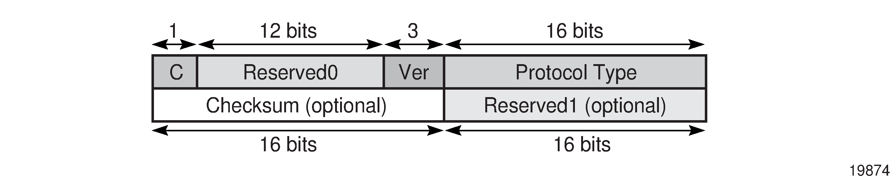
GRE header
The GRE header format is shown in GRE header and described in GRE header descriptions.
Field |
Description |
|---|---|
C |
Specifies whether there is a checksum in the header If set to 1, both the checksum and reserved1 fields must be present In the network egress (transmit) direction, the C bit is always set to 0; therefore, the checksum and reserved1 fields are omitted from the header. The GRE header is therefore always 4 bytes (32 bits) in the network egress direction. In the network ingress direction, the C bit validity is checked. If it is set to a non-zero value, the GRE packet is discarded and the IP discards counter is increased. |
Reserved0 |
Indicates whether the header contains optional fields The first 5 bits of the field are always set to 0 and bits 6 to 12 are reserved for future use and also set to 0 |
Ver |
Always set to 000 for GRE At network ingress, if a GRE packet is received with the version field set to any value other than 000, the packet is discarded and the IP discards counter is increased |
Protocol type |
Specifies the protocol type of the original payload packet—identical to Ethertype with the only supported option being MPLS unicast (0x8847) |
Checksum (optional) |
Not applicable |
Reserved1 (optional) |
Not applicable |
Payload packet
The payload encapsulation format depends on the type of service that is being carried over GRE-MPLS. The payload encapsulation format for GRE services is shown in GRE service payload packet over Ethernet and described in GRE service payload packet descriptions.

Field |
Description |
|---|---|
Eth |
The Layer 2 transport header The only Layer 2 protocol supported is Ethernet MTU size depends on the encapsulation type (14 bytes for null encapsulation and 18 bytes for dot1q encapsulation) The Ethertype is always set to IP (0x800) |
IP |
Indicates the transport protocol IPv4 is the transport protocol for GRE-MPLS |
GRE |
Indicates the encapsulation protocol |
MPLS service header |
The MPLS service label identifies the service and the specific service element being transported For VLL and VPWS services, the label references the pseudowire that was statically configured, or signaled via T-LDP or BGP signaling For VPLS services, the label references a particular VPLS pseudowire that was signaled via T-LDP or BGP signaling to allow the end-to-end VPLS service For VPRN services, the label references either a spoke SDP pseudowire associated with the VPRN, or an MP-BGP advertised route that has been signaled via BGP to allow the end-to-end VPRN service |
CW for VLL and VPWS |
The pseudowire Control word (CW) is a 32-bit (4-byte) field that is inserted between the VC label and the Layer 2 frame For more information about the Control word, see "Pseudo-wire Control word" in the 7450 ESS, 7750 SR, 7950 XRS, and VSR Layer 2 Services and EVPN Guide. |
Services payload |
The services payload is the payload of the service being encapsulated For VLL, VPWS, and VPLS, this is a Layer 2 frame with either null or with dot.1q encapsulation For VPRN, this is a Layer 3 IPv4 or IPv6 packet without Layer 2 information |
At network egress over a cellular port, the destination IP address of the GRE-MPLS IP header is always the far-end IP address that was either configured for the SDP, or learned through BGP routing. If the far-end address is for a cellular port on another 7705 SAR-Hm series node, then that address could be either the system IP address or the cellular PDN interface IP address, depending on the mode of operation deployed at that far-end location. The source IP address of the GRE-MPLS IP header is always set to the cellular PDN interface IP address. This address may be statically configured or dynamically assigned to a cellular port. For information about the PDN router interface modes of operation and how the PDN router interface IP address is assigned, see PDN router interfaces.
At the cellular port network ingress, the destination IP address in the IP header is the same as the cellular PDN interface IP address, because this IP address is the only address reachable over the LTE network. The source IP address of the IP header matches the far-end IP address associated with the GRE-MPLS tunnel. If the packet originates from another cellular port over the cellular network, the source IP address matches the cellular IP address used by the remote node. If the packet originates from another node that is Ethernet connected, then the source IP address is typically the system IP address of those nodes.
At network egress over an Ethernet interface, the source IP address is always set to the node system IP address; the destination IP address is set to one of the following:
the system IP address of the service router on which the GRE SDP is configured
the far-end interface address
a loopback address
GRE SDP tunnel fragmentation and reassembly
It is possible to transport services over GRE-MPLS tunnels when the service MTU is larger than the cellular interface MTU. This requires the GRE-MPLS packets to be fragmented and reassembled using GRE SDP fragmentation and reassembly operations. For information, see the 7450 ESS, 7750 SR, 7950 XRS, and VSR Services Overview Guide, "GRE SDP tunnel fragmentation and reassembly".
GRE SDP termination on router interface IP address
In some applications, an Ethernet interface is required to operate as a network interface and originate and terminate GRE-MPLS packets. If the application requires that GRE-MPLS packets terminate on the interface IP address instead of on the system IP address, then GRE SDP termination on the router interface IP address functionality is available. For information, see the 7450 ESS, 7750 SR, 7950 XRS, and VSR Services Overview Guide, "GRE SDP termination on router interface IP address".