Interfaces
This chapter provides overview information about the types of interfaces supported on 7705 SAR-Hm series routers.
Topics in this chapter include:
-
-
Port State and Operational State
Port Cross-Connect
PXC Terminology
-
Overview
PXC sub-ports
PXC statistics
Basic PXC provisioning
Health monitoring on the PXC
Configuration example
Configuration process overview
Configuration notes
Configuration overview
This guide uses the term preprovisioning in the context of preparing or preconfiguring ports and interfaces before enabling them. When the entity is in a no shutdown state (administratively enabled), the entity is considered provisioned.
Chassis IOM and MDAs
The 7705 SAR-Hm series routers have a fixed physical configuration that uses an integrated control and switching functional block. The Input/Output module (IOM) and Media Dependent Adapters (MDAs) are also integrated into the chassis.
On the CLI, a port is identified using the format slot/mda/port. The slot ID identifies the IOM and is always 1. The MDA identifiers are:
1/1 for the cellular MDA and for the GNSS receiver
1/2 for the Ethernet MDA
1/3 for the serial port MDA
1/4 for the WLAN port MDA
1/5 for the virtualized integrated ISA MDA, for IPSec, IP tunnel, Network Address Translation (NAT), and Application Assurance (AA) firewall functionality
1/6 for the virtualized integrated ISA MDA, for IPSec, IP tunnel, NAT, and AA firewall functionality
On the 7705 SAR-Hm, MDAs 1/1 through 1/4 are automatically provisioned and cannot be deprovisioned. MDAs 1/5 and 1/6 are not automatically provisioned, but can be provisioned and deprovisioned. When they are deprovisioned, the operator must reset the node to ensure the MDAs are completely deprovisioned before being reprovisioned.
On the 7705 SAR-Hmc, MDAs 1/1, 1/2, and 1/3 are automatically provisioned. MDAs 1/5 and 1/6 are not automatically provisioned, but can be provisioned and deprovisioned. When MDAs 1/5 and 1/6 are deprovisioned, the operator must reset the node to ensure the MDAs are completely deprovisioned before being reprovisioned.
CLI port Identifiers lists the CLI port identifiers for each port type on the chassis.
Port type |
CLI identifier |
Variable definition |
|---|---|---|
Cellular |
1/1/port-id |
port-id is the port number, 1 or 2 |
Ethernet |
1/2/port-id |
port-id is the port number:
|
RS-232 |
1/3/port-id |
port-id is the port number, 1 or 2 |
WLAN |
1/4/port-id |
port-id is the port number, 1 or 4 |
There are virtual ports in the CLI for the isa-tunnel-v, the isa-bb-v, and the isa-aa-v virtualized MDAs.
The following chassis and card names are used on the CLI:
- integrated control and switching functional block—cpm-sar-hm or cpm-sar-hmc
IOM—iom-sar-hm or iom-sar-hmc
cellular MDA 1/1—i2-cellular
Ethernet MDA in slot 1/2—i6-10/100eth-tx or i3-10/100eth-tx
serial port MDA in slot 1/3—i2-sdi
WLAN port MDA in slot 1/4—i1-wlan or blank
virtualized integrated ISA MDA in slot 1/5—isa-tunnel-v, isa-bb-v, or isa-aa-v
virtualized integrated ISA MDA in slot 1/6—isa-tunnel-v, isa-bb-v, or isa-aa-v
The following CLI output shows the factory-provisioned settings when the show card state command is issued on the 7705 SAR-Hm.
*A:Dut-C# show card state
===============================================================================
Card State
===============================================================================
Slot/  Provisioned Type                  Admin Operational   Num   Num Comments
Id         Equipped Type (if different)  State State         Ports MDA
-------------------------------------------------------------------------------
1      iom-sar-hm                        up    up                  6
1/1    i2-cellular                       up    up            2
1/2    i6-10/100eth-tx                   up    up            6
1/3    i2-sdi                            up    up            2
1/4    i1-wlan                           up    up            2
1/5    (not provisioned)                 up    unprovisioned 4
           isa-ms-v
1/6    (not provisioned)                 up    unprovisioned 4
           isa-ms-v
A      cpm-sar-hm                        up    up                      Active
===============================================================================
The CLI output for the example above looks similar to the following output when the config>card 1 and the info commands are issued on the 7705 SAR-Hm:
*A:Dut-C# configure card 1
*A:Dut-C>config>card# info
----------------------------------------------
        card-type iom-sar-hm
        mda 1
            mda-type i2-cellular
            no shutdown
        exit
        mda 2
            mda-type i6-10/100eth-tx
            no shutdown
        exit
        mda 3
            mda-type i2-sdi
            no shutdown
        exit
        mda 4
            mda-type i1-wlan
            no shutdown
        exit
        no shutdown
----------------------------------------------
*A:Dut-C>config>card#
The following CLI output shows the factory-provisioned settings when the show card state command is issued on the 7705 SAR-Hmc.
A:Dut-C# show card state
===============================================================================
Card State
===============================================================================
Slot/  Provisioned Type                  Admin Operational   Num   Num Comments
Id         Equipped Type (if different)  State State         Ports MDA
-------------------------------------------------------------------------------
1      iom-sar-hmc                       up    up                  6
1/1    i2-cellular                       up    up            2
1/2    i3-10/100eth-tx                   up    up            3
1/3    i2-sdi                            up    up            2
1/5    (not provisioned)                 up    unprovisioned 2
           isa-ms-v
1/6    (not provisioned)                 up    unprovisioned 2
           isa-ms-v
A      cpm-sar-hmc                       up    up                      Active
===============================================================================
The CLI output for the example above looks similar to the following output when the config>card 1 and the info commands are issued on the 7705 SAR-Hmc:
A:Dut-C# configure card 1
A:Dut-C>config>card# info
----------------------------------------------
        card-type iom-sar-hmc
        mda 1
            mda-type i2-cellular
            no shutdown
        exit
        mda 2
            mda-type i3-10/100eth-tx
            no shutdown
        exit
        mda 3
            mda-type i2-sdi
            no shutdown
        exit
        no shutdown
----------------------------------------------
*A:kansarhmc1: Dut-A>config>card#
Ports
This section provides information about the types of ports supported on the system.
Port types
The system supports the port types listed below.
Cellular
The cellular interface supports dual SIM operation using major carrier frequency bands in North America, EMEA, and APAC. For more information about cellular ports, see Cellular MDA and ports.
Ethernet
The system supports Fast Ethernet (10/100Base-T) ports. The Ethernet ports are typically connected to field devices, such as Intelligent Electronic Devices (IEDs), AMI collectors, supervisory modules, weather monitoring devices, cameras, and other hosts.
In some cases, an Ethernet port may be connected to a 7705 SAR-18, 7705 SAR-8, 7705 SAR-H, or 7705 SAR-Hc node, which will use the system's cellular port as a backup link.
For more information about Fast Ethernet ports, see the 7450 ESS, 7750 SR, 7950 XRS, and VSR Interface Configuration Guide, '"Port types".
Serial
RS-232 asynchronous ports are typically used for connecting to remote SCADA equipment. The ports support full-duplex communication and interface speeds of 600 b/s, 1200 b/s, 2400 b/s, 4800 b/s, 9600 b/s, 19 200 b/s, 38 400 b/s, 57 600 b/s, and 115 200 b/s. The serial ports can be configured to support raw socket transport; see Serial transport over raw sockets for more information.
Alarm
For information about the alarm port and the number of supported alarm inputs and outputs, see the SAR-Hm and SAR-Hmc Chassis Installation Guide.
For information about configuring alarm inputs, see the 7450 ESS, 7750 SR, 7950 XRS, and VSR Basic System Configuration Guide.
Alarm inputs are configured using the config>system>alarm-contact-input command and sub-commands. For information, see the 7450 ESS, 7750 SR, 7950 XRS, and VSR Classic CLI Command Reference Guide.
To display the status of the alarm inputs, use the show>system>alarm-contact-input all command; see the 7450 ESS, 7750 SR, 7950 XRS, and VSR Clear, Monitor, Show, and Tools CLI Command Reference Guide for information.
WLAN
The WLAN interface supports the IEEE 802.11 b/g/n WLAN standard. The interface is enabled as a WLAN access point (AP) that remote WLAN stations can connect to. For more information, see Wireless LAN interface. WLAN traffic that is received from WLAN stations connected to the WLAN AP is transported over a Layer 2 service using an Epipe. See the 7705 SAR-Hm and SAR-Hmc Main Configuration Guide for details about configuring services for the WLAN AP.
Port features
For general information about port features, see the 7450 ESS, 7750 SR, 7950 XRS, and VSR Interface Configuration Guide, "Port state and operational state".
MTU configuration guidelines
Observe the general rules described in "MTU configuration guidelines" in the 7450 ESS, 7750 SR, 7950 XRS, and VSR Interface Configuration Guide when planning service and physical MTU configurations.
Default and maximum MTU values
MTU default and maximum values lists the default and maximum MTU values for Fast Ethernet ports, cellular ports, and the WLAN interface.
For information about how to modify the MTU defaults, see "Modifying MTU defaults" in the 7450 ESS, 7750 SR, 7950 XRS, and VSR Interface Configuration Guide.
Port type |
Mode |
Default |
Maximum |
|---|---|---|---|
Fast Ethernet |
Access/network |
1514 bytes (includes Ethernet header, but excludes Ethernet CRC) |
1622 bytes |
Cellular interface |
Network (PDN router interface) |
None Operators must configure this value on the PDN router interface to ensure correct operation of a cellular port. |
1486 bytes |
WLAN interface |
Access |
1500 bytes (non-configurable) |
1500 bytes (non-configurable) |
MTU considerations over a cellular port
The cellular port IP layer MTU is derived from the PDN router interface that is configured for the cellular port. By default, the PDN router interface MTU is not set. To operate the cellular interface without failures, an MTU value that is less than or equal to 1486 bytes must be configured (using the ip-mtu command) for the PDN router interface. For information about configuring the PDN router interface, see "PDN router interface command descriptions" in the 7705 SAR-Hm and SAR-Hmc Main Configuration Guide.
Mobile networks often require a strict IP layer MTU for the LTE interface that is less than or equal to1486 bytes. Consult with the cellular service provider about the correct IP layer MTU value to set for the associated PDN router interface.
The SAP MTU settings must also correctly account for the PDN router interface IP layer MTU, as services that are transported over the cellular interface are impacted by this configuration.
For example, if a cellular provider allows an IP layer MTU of 1486 bytes, the following calculations and values must be considered when setting up services over a cellular port.
For BGP and T-LDP protocols, the MTU of protocol packets must be set to 1486 bytes or less. For information about BGP path MTU discovery and LDP path MTU discovery, see the path-mtu-discovery command in the 7450 ESS, 7750 SR, 7950 XRS, and VSR Classic CLI Command Reference Guide.
For Layer 3 services over a VPRN service using GRE transport, the SAP MTU must be set as follows:
SAP MTU = {1486 bytes - (GRE packet overhead) - (VPRN service label)}
SAP MTU = {1486 bytes- (24 bytes) - (4 bytes)}
SAP MTU = 1458 bytes
For Layer 3 services over a VPRN service using GRE transport with NGE enabled, the SAP MTU must be set as follows:
SAP MTU = {1486 bytes - (GRE packet overhead) - (VPRN service label) - (NGE overhead)}
SAP MTU = {1486 bytes - (24 bytes) - (4 bytes) - (77 bytes)}
SAP MTU = 1381 bytes
For Layer 2 services over a VPLS service using GRE transport, the SAP (port) MTU must be set as follows:
SAP MTU = {1486 bytes - (GRE packet overhead) - (VPLS service label)}
SAP MTU = {1486 bytes - (24 bytes) - (4 bytes)}
SAP MTU = 1458 bytes
For Layer 2 services over a VPLS service using GRE transport with NGE enabled, the SAP MTU must be set as follows:
SAP MTU = {1486 bytes - (GRE packet overhead) - (VPLS service label) - (NGE overhead)}
SAP MTU = {1486 bytes - (24 bytes) - (4 bytes) - (77 bytes)}
SAP MTU = 1381 bytes
For Layer 2 services using an Epipe VLL/VPWS service with a control word, an additional 4 bytes of overhead is required for the control word. Therefore, the following SAP (port) MTU must be set as follows:
SAP MTU = {1486 bytes - (GRE packet overhead) - (VLL service label) - (CTL word)}
SAP MTU = {1486 bytes - (24 bytes) - (4 bytes) - (4 bytes)}
SAP MTU = 1454 bytes
For Layer 2 services using an Epipe VLL/VPWS service with a control word and NGE enabled, an additional 4 bytes of overhead is required for the control word and 4 bytes of NGE overhead is added. Therefore, the following SAP (port) MTU must be set as follows:
SAP MTU = {1486 bytes - (GRE packet overhead) - (VLL service label) - (CTL word) – (NGE overhead)}
SAP MTU = {1486 bytes - (24 bytes) - (4 bytes) - (4 bytes) - (81 bytes)}
SAP MTU = 1373 bytes
The SAP MTU of Layer 2 services can be increased to accommodate larger packets that are closer to the Ethernet port maximum MTU value by using GRE SDP fragmentation and reassembly. See "GRE SDP tunnel fragmentation and reassembly" in the 7705 SAR-Hm and SAR-Hmc Main Configuration Guide.
MTU considerations over the WLAN interface
The WLAN port MTU value is set to 1500 bytes and cannot be changed. Since cellular ports have a lower MTU with a maximum of 1486 bytes, and WLAN traffic from stations connected to the WLAN AP is carried over an IP/MPLS service that adds additional overhead to traffic traveling over cellular ports, the operator must understand the requirements of the MTU for their applications in order to successfully use the WLAN interface.
For example, when the WLAN interface AP is connected to the Nokia WLAN GW using an Epipe service, there is at most 1454 bytes available to carry a Layer 2 packet for the WLAN AP packet that includes a Layer 2 header of 14 bytes (see MTU considerations over a cellular port for information about the SAP MTU of an Epipe service over a cellular port). In order to successfully send these packets over a cellular port without further modification, the MTU of the IP payload in the WLAN AP Layer 2 packet must be restricted to 1440 bytes.
The MTU of the WLAN interface can be handled in one of two ways:
by modifying the MTU value on clients that are connecting to the WLAN AP such that they send traffic that conforms to the service MTU of the IP/MPLS transport service, minus the 14 byte Layer 2 overhead
by configuring GRE SDP fragmentation and reassembly on the node to allow packets that require an MTU greater than that available on the cellular interface to be fragmented and reassembled when carried over the cellular interface
Serial transport over raw sockets
Serial transport over raw sockets provides the capability of transporting serial data, in the form of characters, over an IP transport service within a Layer 3 IP/MPLS VPRN service. A raw socket allows direct sending and receiving of IP packets without any protocol-specific transport layer formatting. For information about raw socket IP transport services, see "Raw socket IP transport service" in the 7705 SAR-Hm and SAR-Hmc Main Configuration Guide.
The feature provides the functionality for a local host to listen to and open raw socket sessions from remote hosts, and for a remote host to initiate and open raw socket sessions to local hosts. The local and remote host functions support TCP or UDP sessions (but not both concurrently) over the IP transport service.
Raw sockets are supported for RS-232 ports on the node.
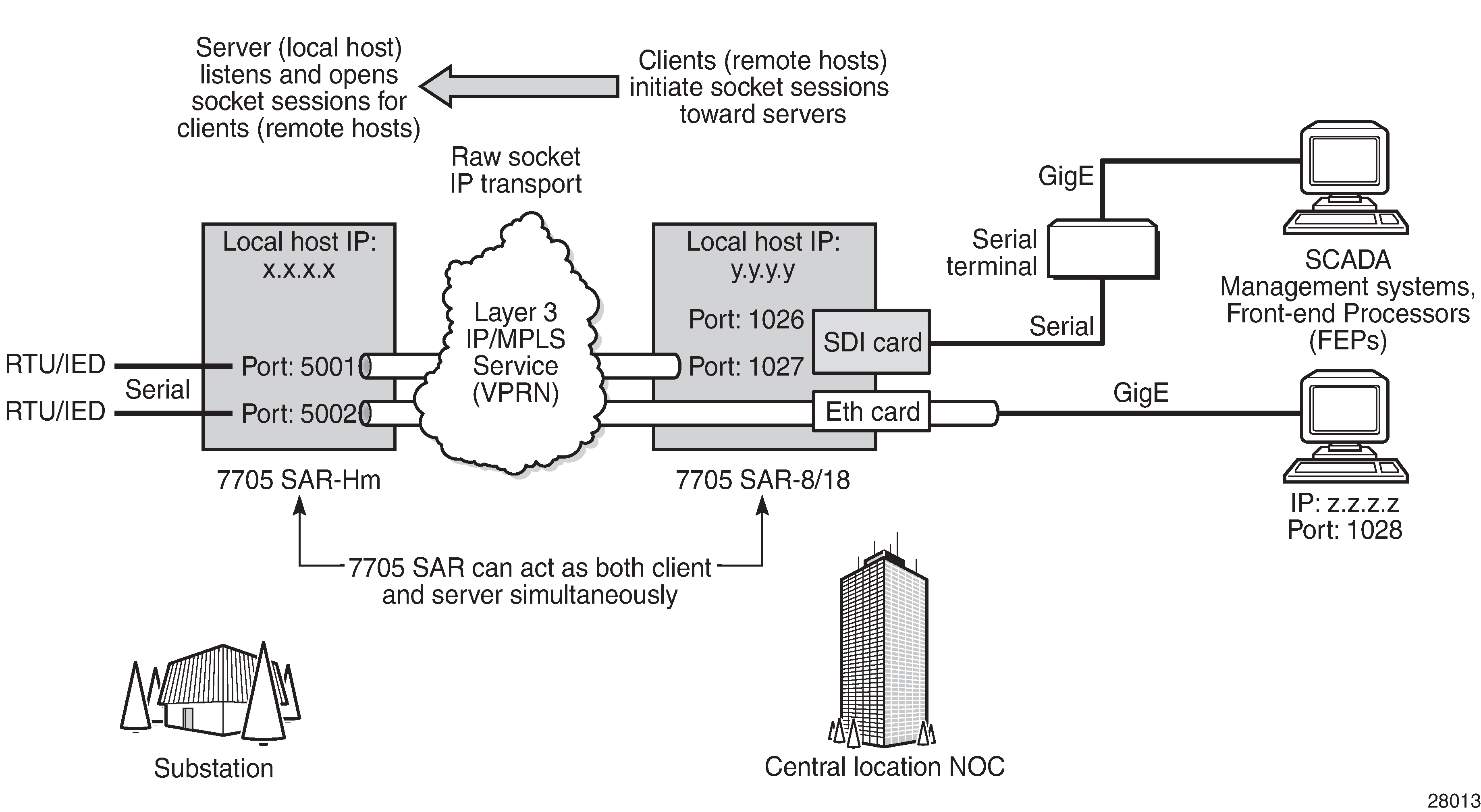
Serial transport over raw socket application shows an example of a raw socket application, where serial data is transferred between RTUs and a utility's SCADA management system using an IP transport service across a Layer 3 VPRN service that includes 7705 SAR-Hm and 7705 SAR-8/7705 SAR-18 nodes.
A raw socket local host (acting as a server) at the 7705 SAR-Hm substation listens to TCP sessions that originate at the 7705 SAR-8 or 7705 SAR-18 central location network operations center (NOC). The 7705 SAR-8 or 7705 SAR-18 at the NOC is connected to two front-end processors (FEPs), one via a serial port and another via an Ethernet port. The serial port on the 7705 SAR-8 or 7705 SAR-18 is configured as a remote host (acting as a client) that initiates TCP/UDP sessions toward the RTU at the 7705 SAR-Hm substation when traffic is received from the FEP over the serial port. These TCP/UDP sessions are transported over the IP/MPLS network using IP transport service over a VPRN service. The serial data transported over the TCP/UDP session and received at the 7705 SAR-Hm is then sent over the serial link toward the RTU. TCP/UDP sessions received from the FEP over the Ethernet port are transported over a VPRN service (that is, there is no need for serial port remote host configuration in this case).
Multiple FEPs can poll a single RTU. If multiple sessions attempt to transmit serial data on the serial port simultaneously, the 7705 SAR-Hm queues packets per session and ensures that all data for one session is sent out before processing another session's data, ensuring that sessions do not overlap one another.
Raw socket configuration
A raw socket IP transport interface can be configured for each RS-232 serial port on a node. This allows the serial port to receive TCP connections or UDP session packets from multiple remote hosts, or to create new sessions to remote hosts in order to send and receive serial data to and from those remote hosts.
There are port-level and service-level configuration requirements for a raw socket serial port to send and receive serial data in either server mode, client mode, or both modes.
Raw socket port-level configuration includes defining the end of packet checking parameters (idle time, length, special character) and the inter-session delay for transmitting session data over the serial link.
At the service level, an IP transport subservice is created within a VPRN service to associate the serial port with the VPRN service. TCP/UDP encapsulated serial data is routed within the corresponding Layer 3 VPRN service. The required configuration includes IP transport subservice local host and remote host configuration, TCP timers, and session control.
See Serial raw socket interface configuration commands for information about the required port-level configuration. For information about how the IP transport subservice operates within a VPRN service, as well as information about the required system-level configuration, see "Raw socket IP transport service" in the 7705 SAR-Hm and SAR-Hmc Main Configuration Guide.
Raw socket packet processing
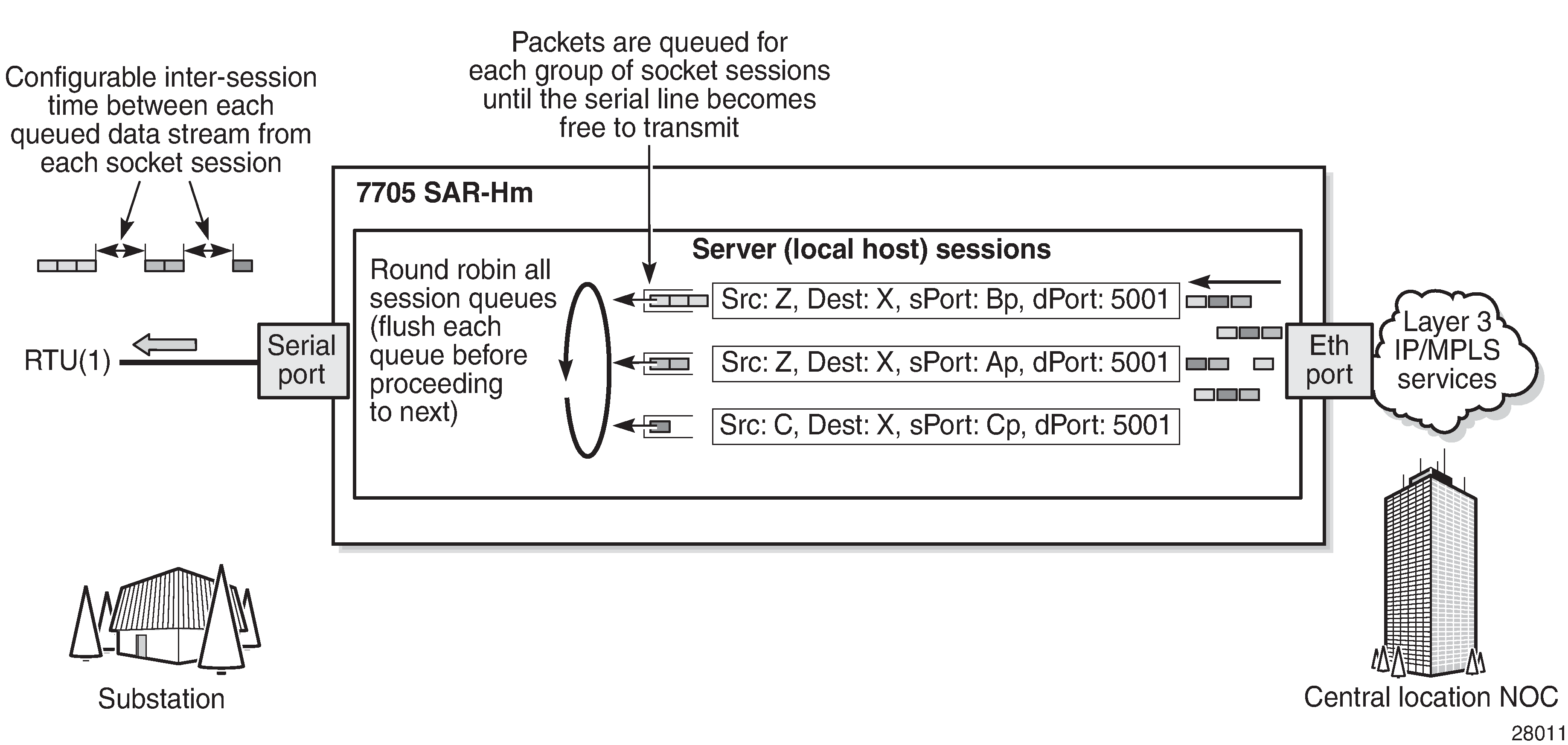
Raw socket packet processing illustrates how raw socket packets are processed over a serial link.
Session data attempting to access the serial port is queued. One queue is maintained per session. The purpose of the session queue is to prevent two different flows of packets from interleaving out the serial port and creating unreadable messages. When data is being transmitted over the serial link for a session, any other session's data is queued until the first session has emptied its queue. The next session's data is transmitted over the serial link only after the inter-session-delay timer expires. Each session's data is sent out in round-robin fashion.
Raw socket processing for UDP sessions
When the local host receives a UDP packet from a remote host, it queues the packet and sends it over the serial link. The local host remembers the UDP session while there is still data to send from the serial link. If further packets are received for the same session, they are queued behind the already queued packet. After all the queued data has been sent over the serial link, the session is removed from the system. An associated UDP remote host for the serial link must be configured to have serial data sent back to the remote host from the serial port.
When a packet is received from the serial link based on end-of-packet (EOP) requirements, the data is copied and sent in a UDP packet to each configured remote host.
Raw socket processing for TCP sessions
An open TCP session from a remote host to a raw socket's local host is kept open until either the remote host terminates the session or the TCP inactivity timer expires. When a TCP session is open, all packets received from the remote host are queued for the raw socket serial link and sent over the serial link until no packets remain in the queue. If multiple sessions are open toward the local host, and each is receiving data, then each session's data is queued and then sent over the serial link in round-robin fashion for each session until no packets remain. When a packet is received over the serial link, it is copied to each open TCP session and transmitted to the remote host.
Raw socket squelch functionality
A condition may occur where the end device connected to the serial port continues to send out a continuous stream of data after the normal response period has expired. This can prevent the far-end remote host or master equipment from receiving data from other end devices in the network. To resolve this condition, the squelch command can be used on the raw socket at the port level (it is disabled by default). This stops the socket from receiving any more data from the problematic device.
If the command is enabled, the node will monitor the serial port for a constant character stream. A configurable squelch delay period, using the squelch-delay command, is used to determine how long to measure the constant character stream before initiating the squelch function. If the squelch function is initiated, the port is considered locked up and an alarm is raised indicating the lock-up and that the squelching function has been triggered.
The serial port can be forced out of squelch and put back to normal, either manually using the squelch-reset command or automatically using the unsquelch-delay command. The unsquelch-delay command defines the time to wait after squelch is initiated before it is removed.