
Basic system configuration
The 7705 SAR-Hm series of routers provides basic system configuration support as covered in the following topics:
CLI usage
For general information about CLI usage, see the 7450 ESS, 7750 SR, 7950 XRS, and VSR Classic CLI Command Reference Guide, "Classic CLI overview".
File system management
The 7705 SAR-Hm series routers use the SR OS file system to store files used and generated by the system; for example, image files, configuration files, logging files, and accounting files.
The file commands allow you to copy, create, move, and delete files and directories, navigate to a different directory, and display file or directory contents and the image version. The routers in the 7705 SAR-Hm series use on-board flash memory for storing software images. The file system on the 7705 SAR-Hm series of routers is case sensitive.
For more information about file system management support, see the 7450 ESS, 7750 SR, 7950 XRS, and VSR Basic System Configuration Guide, "File management".
7705 SAR-Hm series file system
The system ships from the factory with the BOF configured with an empty primary-config, and with auto-discover enabled. Files on the integrated flash memory device shows the directory structure and filenames on the integrated flash memory device with the suggested BOF configuration for the primary-config and primary-image files.
The primary-config file is typically located cf3:/config.cfg. Nokia recommends using the directory structure cf3:/TiMOS-SR-m.n.Yz to hold multiple releases. The location and filenames can be changed in the BOF if required.
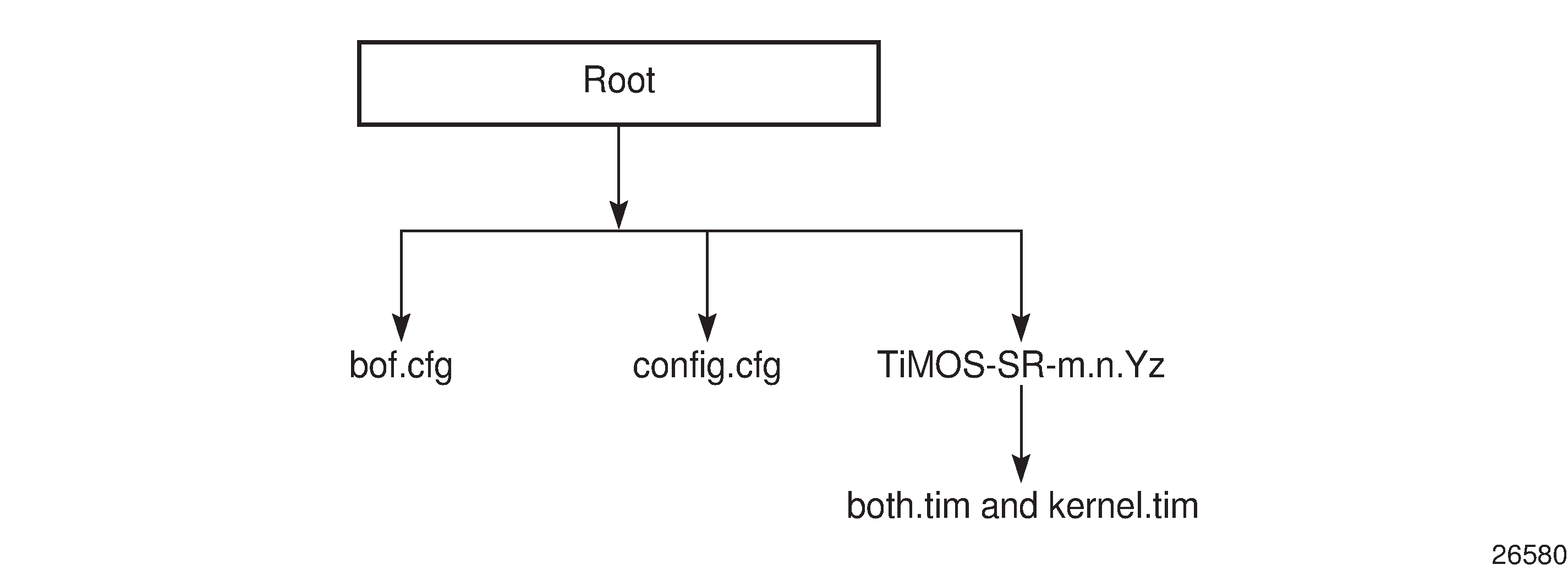
Files on the integrated flash memory device are:
both.tim — application software file
kernel.tim
-
support.tim
-
boot.tim
-
vxrom.bin
-
u-boot.bin
-
fman-ucode.bin
-
mc7475_fw.bin
See the 7705 SAR-Hm and SAR-Hmc Software Release Notes for more information.
See the 7450 ESS, 7750 SR, 7950 XRS, and VSR Basic System Configuration Guide for a full description of the TiMOS file system.
Boot options file
The primary copy of the system software is factory installed on the internal flash drive in directory cf3.
When the node is first powered on, by default the system searches for the bof.cfg file (also known as the BOF file) on the integrated flash. The system reads and executes the system initialization commands configured in the boot option file (BOF).
The BOF in the node is factory configured with Auto Discovery Protocol (ADP-HM) enabled. ADP-Hm starts automatically unless the auto-discover option is disabled.
The default ADP-Hm configuration in the BOF is as follows:
auto-discover private.nokia.nsp.primary.nms
auto-discover private.nokia.nsp.secondary.nms
For example:
*A:Dut-A# show bof
===============================================================================
BOF (Memory)
===============================================================================
    primary-image cf3:/TiMOS-19.10.R1/
 <lines removed...>

    console-speed    115200
    auto-discover    private.nokia.nsp.primary.nms
    auto-discover    private.nokia.nsp.secondary.nms
===============================================================================
*A:Dut-A#
ADP-Hm can be disabled manually by executing the tools>perform>auto-boot terminate command and saving the BOF. See Terminating ADP-Hm for more information.
See the 7450 ESS, 7750 SR, 7950 XRS, and VSR Basic System Configuration Guide, "System Initialization and boot options" for more information about boot options.
ADP-Hm
The Nokia NSP Network Functions Manager - Packet (NSP NFM-P) supports the Auto Discovery Protocol (ADP) process for the node. This process is known as ADP-Hm. The ADP-Hm process provides all initialization and commissioning functions automatically for a newly installed node.
After one or more SIMs have been installed in a 7705 SAR-Hm series node, when the node is powered on for the first time and any required password change has been made (see Prerequisites for ADP-Hm), the ADP-Hm process running on the node configures a cellular port using the SIM in SIM slot 1 and an Ethernet port (port 1/2/1), and establishes connectivity to the NSP NFM-P. The ADP-Hm process then waits for the NSP NFM-P to complete the discovery and configuration of the node.
This section describes the following topics:
See Network Services Platform functional overview for information about NSP NFM-P management functions. See the NSP NFM-P User Guide for more information and procedures to manage the ADP-Hm process.
Prerequisites for ADP-Hm
The prerequisites to allow the ADP-Hm process to automatically discover a 7705 SAR-Hm series router are:
An NSP NFM-P has been procured, installed, and is managing one or more head-end nodes defined for the cellular domain.
A valid SIM card is inserted into SIM slot 1 on the node. For dual SIM operation a second SIM is inserted into SIM slot 2.
For those variants of the 7705 SAR-Hm series node with a unique factory-set password which must be changed at first login, the new password must match the password expected by the NSP NFM-P being used to discover the node during the ADP-Hm process.
The operator has determined whether the one-step or two-step process will be used by the NSP NFM-P and configures it as such.
For each carrier private VPN service associated with each installed SIM, a route exists for the NFM-P from the carrier private VPN service or the private-LTE cellular Evolved Packet Core (EPC) toward the cellular domain head-end node or nodes that have reachability to the NSP NFM-P. These gateway nodes allow new 7705 SAR-Hm nodes running ADP-Hm to reach the NSP NFM-P.
A route for the subnet of the cellular domain nodes exists from the cellular domain head-end node to the new node to be discovered. For initial installation of a cellular domain, IP addresses are typically allocated from a /24 or /18 IP address range and the associated routes can be used. In a dual SIM deployment, there must exist a route for the IP addresses associated with each SIM.
A default Access Point Name (APN) or Virtual Private Network (VPN) service has been procured from the service provider for the SIMs that are installed in the node. If a fixed/static IP address for the IMSI associated with the SIM is required, the address can be allocated in two ways for each SIM:
by direct Home Subscriber Server (HSS) allocation (such as when a mobile carrier assigns IP addresses for the SIM and IMSI).
by a Radius/AAA/DHCP server owned by the enterprise operator. This method uses a process known as deferred IP allocation between the Home Subscriber Server (HSS) and the PGW of the wireless service provider. When the node first connects and authenticates with the HSS of the wireless provider, the default APN associated with the service indicates that the IP allocation is deferred to the enterprise Radius/AAA/DHCP server. After the PGW learns the static IP address from the server, it is sent to the node in the PDP address IE when the default bearer is established.
The PGW to which the node will attach using the SIM in slot 1 is configured with additional Protocol Configuration Options (PCO) for the APN. The PCO must include the following two values:
dns-server-ipv4 primary – for example, config/mobile/pdn/apn/pco/dns-serveripv4 primary
dns-server-ipv4 secondary – for example, config/mobile/pdn/apn/pco/dns-serveripv4/backup
A primary and secondary DNS server (available from a wireless provider or owned by an enterprise operator) are configured to resolve the NSP NFM-P IP primary and backup NSP NFM-P IP addresses.
A SAR-Hm.xml file is loaded on the NSP NFM-P for the cellular domain where the node will reside after discovery. The XML file lists the SIM IMSIs for SIM slot 1 and the node's associated system IP addresses (if specified in the XML file) of each node that needs to be discovered. In a dual SIM deployment, the SIM in slot 2 is not referred to in this XML file. See the NSP NFM-P User Guide for more information about configuring cellular domains and the associated XML files.
The operator has enabled ADP-Hm on the NSP NFM-P for the associated prefix addresses of the nodes to be discovered using ADP-Hm in the cellular domain.
The ADP-Hm process
The following sections describe the three phases of the ADP-Hm process:
Network discovery (phase 1)
When the node boots up initially, it runs the application load, executes the config file (which is empty), and then checks the BOF to determine if ADP-Hm needs to run. If ADP-Hm is enabled, the ADP-Hm process starts and performs the tasks listed below:
-
The ADP-Hm process configures Ethernet port 1/2/1, which can be used for the first step of the two-step process if using Ethernet for step 1 is enabled on the NSP NFM-P. The following CLI output shows the configuration:
configure port 1/2/1
        ethernet
            mode network
            hold-time up 5 down 5
        exit
        no shutdown
    exit

    router Base
        interface "IF-1/2/1"
            port 1/2/1
            no shutdown
        exit
        interface "system"
            no shutdown
        exit
    exit
The ADP-Hm process initializes the cellular port that uses SIM1 for PDN connectivity using the default PDN profile, which has a blank APN. When the cellular port attempts to connect to the network, it uses this PDN profile. If the carrier requires an APN other than the default in order for the cellular port to connect to the network, the cellular port can learn the correct APN from the network if the carrier supports that capability. If the carrier does not support devices learning the APN but requires an APN other than the default, then the operator must configure a PDN profile at the system level with the correct APN and assign that PDN profile to cellular port 1/1/1. See the 7705 SAR-Hm and SAR-Hmc Interface Configuration Guide for details about configuring a PDN profile and assigning it to a cellular port.
After the cellular port connects to the network, ADP-Hm assigns the name pdn1-sim1 to the PDN router interface. The name of the router interface must not change during the ADP-Hm process. The PDN router interface can operate in one of three modes. ADP-Hm uses the dynamic cellular interface IP mode of operation. See Dynamic cellular interface IPv4 mode for more information.
The ADP-Hm process creates a loopback interface with a default name for the PDN interface (such as "pdn1-loopback"). No IP address is assigned to the loopback because it is operating in dynamic cellular interface IP mode.
The ADP-Hm process uses this loopback interface as the unnumbered interface for the PDN router interface
The following CLI output shows the configuration:
configure router
        interface "pdn1-loopback"
            loopback
            no shutdown
         exit
        interface "pdn1-sim1" pdn
             port 1/1/1
             unnumbered "pdn1-loopback"
             no shutdown
         exit
    exit
exit
If the cellular network authenticates and accepts the new node onto the network, a default bearer is established and the following information is provided to the node for the APN to which the node connects:
the IP address of the cellular interface
the DNS server IP addresses
The configuration is not saved. (Phase 2) NSP NFM-P Discovery begins.
NSP NFM-P discovery (phase 2)
During the NSP NFM-P discovery phase, the node sends DNS query messages to the DNS server addresses discovered from the previous phase. The node then learns the IP addresses of the NSP NFP-P and sends SNMP traps toward the NSP NFP-P.
The following NSP NFM-P URL names are set for the auto-discovery command in the BOF by default:
- auto-discover private.nokia.nsp.primary.nms
- auto-discover private.nokia.nsp.secondary.nms
-
another appropriate name, if required
-
an IP address (which eliminates the requirement for a DNS server)
The node sends the DNS query message every 5 seconds until a DNS query response message is received with a valid IP address for the primary and secondary NSP NFM-P.
One IP address is required for the ADP-Hm process to continue to the next phase. If no DNS query response message is received, ADP-Hm will time-out and reboot the node. After reboot, the ADP-Hm process restarts from the beginning of Network Discovery (Phase 1).
After either the NSP NFM-P primary or secondary IP addresses are known by the node, the NSP NFM-P performs the following:
SNMPv2 trap destinations are set to the NSP NFM-P IP addresses. Log 1 is used to set up the trap destinations.
The node initiates an SNMP trap poll that sends a "Hello" notification trap message to the NSP NFM-P every 15 seconds.
The node waits for the NSP NFM-P to process the Hello request and then ADP-Hm starts the NSP NFM-P Configuration (Phase 3).
NSP NFM-P configuration (phase 3)
In the third phase, the NSP NFM-P secures the node and carries out the remaining commissioning steps on the node.
Throughout this phase, the node sends an SNMPv3 trap to the NSP NFM-P every 15 seconds until the NSP NFM-P executes the tools>perform>auto-boot complete command.
There are two process options available on the NSP NFM-P during this phase. (See the NSP NFM-P user guides for more information about these options.)
1) One-step process – the NSP NFM-P performs all discovery and configuration activities on the node in one step. This allows ADP-Hm to run at the site location from start to finish. After Phase 3 is complete, the node is fully managed and secured. For more information about the one-step process, see One-step process details.
2) Two-step process – the NSP NFM-P configures critical security parameters on the node in the first step where operators can monitor progress in a DMZ or staging facility. The first step is performed using either the cellular interface or Ethernet port 1/2/1. After step one, the node is secured and fully managed by the NFM-P.
The node is powered down and if Ethernet was used during step one, the Ethernet cable is unplugged from port 1/2/1. The node is transported to the installation site where the operator performs the second step. When the node is installed and powered on, the NSP NFM-P completes the network-level configuration for the node. The NSP NFM-P configures such things as default tunnels and services to the head-end nodes, or optionally adds the node to an existing network group encryption (NGE) domain. For more information about the two-step process, see Two-step process details.
One-step process details
In the one-step process, the node is powered on and ADP-Hm completes the entire discovery and configuration of the node in one step.
The NSP NFM-P uses NETCONF over SSHv2 to configure SNMPv3 parameters, including the users and security encryption and authentication keys for SNMPv3. This information is based on the mediation policy configured for the cellular domain in the NSP NFM-P.
The NSP NFM-P then completes the configuration of the node. The following list summarizes the actions that the NSP NFM-P performs on the node:
Creates a strict security association between the chassis information, IMEI, and the SIM in SIM slot 1. After this association is made, the SIM cannot be inserted into another node and managed by the NSP NFM-P without operator intervention to instruct the NSP NFM-P to create a new association between the SIM and a new chassis.
Configures usernames and passwords, scope of control, and associated profiles.
Configures PDN profiles that are used to connect to the cellular network after ADP-Hm is complete. If dual SIM is enabled for the cellular domain in the NSP NFM-P, then the second cellular port and PDN router interface is configured.
Downloads the required radio firmware version for SIM 1 and if dual SIM is enabled, it downloads the radio firmware version for SIM 2. The NSP NFM-P resets the radio so that SIM 1 uses the latest downloaded version.
Downloads the required software load and resets the node to use the latest version of the software.
Downloads the NGE key-group of the NGE domain associated with the cellular domain if the node is to enter the NGE domain. The PDN router interface is also configured with the key-group needed to enter the NGE domain.
If the cellular mode is Static Cellular Interface IP Mode or Dynamic Cellular Interface IP Mode, the NSP NFM-P performs the following configurations toward the head-end nodes of the cellular domain to establish an in-band management service. (For more information, see the Static cellular interface IPv4 mode, and Dynamic cellular interface IPv4 mode sections in this guide.)
Configures a BGP session to each head-end node in the cellular domain that is associated with the first cellular network. The BGP sessions are configured with the PDN router interface associated with SIM 1.
Configures a BGP session to each head-end in the cellular domain that is associated with the second cellular network when two SIMs are required. The BGP sessions are configured with the PDN router interface associated with SIM 2.
Configures an in-band management VPRN service used by the NSP NFM-P to manage the node in-band over the GRE-IMPLS tunnels over the cellular network. This VPRN service can optionally be NGE encrypted to provide an additional layer of security when managing nodes.
If dual SIM is enabled for the cellular domain, the NSP NFM-P performs a manual SIM switch to enable cellular service using the second SIM. It then confirms that the second cellular network and the in-band management VPRN service are working correctly. After the second SIM is verified, the NSP NFM-P performs another manual SIM switch and enables cellular service using the first SIM, as was used throughout the ADP-Hm process.
The NSP NFM-P is responsible for saving the configuration after the actions listed above are executed, and may save the configuration several times over the course of executing them.
After the above actions are completed, the NSP NFM-P stops the ADP-Hm process by executing tools>perform>auto-boot complete command.
NSP NFM-P then disables ADP-Hm so that the discovery process no longer runs; the NSP NFM-P does so by setting the no auto-discover command in the BOF and by clearing all DNS entries, if multiple entries existed.
The system and alarm status LEDs are set and the node is ready for further services configuration. For a description of how LEDs indicate the node status during the ADP-Hm process, see LED operation during the ADP-Hm process.
Two-step process details
In the two-step process, the node is powered on first in a staging area or DMZ for initial NSP NFM-P security configurations and then powered on a second time at the final site location to complete the commissioning process. For the first step, the node uses either the cellular interface or Ethernet port 1/2/1 to communicate with the NSP NFM-P during the commissioning process. The steps are as follows:
-
The node is powered on for the first time and items 1 to 5 as described in One-step process details are executed by the NSP NFM-P. The NSP NFM-P then issues the tools>perform>auto-boot complete command to indicate that step 1 of this process is complete and to stop the ADP-Hm process on the node. The system Status LED on the node turns solid green and the Alarm LED continues to blink, indicating that step 1 has completed and the node can be powered off. For more information, see LED operation during the ADP-Hm process. If Ethernet port 1/2/1 was used for this step, the Ethernet cable is unplugged from the port. The node can be shipped to the site for final installation.
-
The node is powered on for the second time. Because the BOF is set to "auto-discover" it sends SNMPv3 traps to the NSP NFM-P to indicate that the ADP-Hm process is resuming. The NSP NFM-P resumes the ADP-Hm process and items 6 to 8 as described in One-step process details are executed. The NSP NFM-P then saves the configuration and completes the ADP-Hm process. The system Status and Alarm LEDs indicate that ADP-Hm is complete.
When Ethernet port 1/2/1 is used for step 1 of the two-step process, a DHCP server is reachable over the Ethernet interface. The DHCP OFFER or REQ messages sent from the node to the DHCP server contain the following options:
-
chaddr—the client MAC address
-
Option 50—the requested IP address; this address is the same as the address contained in the yiaddr field that was received in the DHCP OFFER message
-
Option 53—the DHCP message type (REQUEST)
-
Option 54—the DHCP server address; this address is the same as the address received in the OFFER message
-
Option 51—the IP address lease time; this value is the same as the lease time received in the OFFER message
-
Option 60—the vendor class identifier; this value is the same as the vendor class identifier in the DISCOVER message
-
Option 61—the client identifier; this value is the same as the client identifier in the DISCOVER message
-
Option 55—the parameter request list:
-
Option 1—the subnet mask value
-
Option 3—the router option (unused if not enabled in the CLI)
-
Option 6—the DNS server option (unused if not enabled in the CLI)
-
Option 54—the DHCP server address
-
Option 121—the static-route option (unused if not enabled in the CLI)
-
The DHCP server returns the following options:
-
Option 3—the router option; the router is installed as the default gateway address
-
Option 6—the DNS server option; the DNS server is installed in the list of DNS servers for the node (up to six servers are supported on the node)
-
Option 121—the static-route option; the static route is installed as a route for the router interface on Ethernet port 1/2/1
The Console during the ADP-Hm process
The Console port can be used to establish a CLI session on a 7705 SAR-Hm series node so that the progress of the ADP process can be monitored. For information about using the Console port to establish a CLI session, see the SAR-Hm and SAR-Hmc Chassis Installation Guide, "Establishing a console connection".
During ADP, the node may reset periodically. The Console session is lost during reset and you must log in to the node again.
You can use the tools>perform>auto-boot command to monitor the ADP process.
In the following example, no ports on the router have been discovered yet.
*A:Dut-A# tools dump auto-boot
===============================================================================
Automated-Provisioning
===============================================================================
Status          : Connecting-To-Network
Failures        : None

Start Time      : TUE MAR 07 17:12:22 2023
End Time        : Never

NMS         (1) : Not Configured
NMS         (2) : Not Configured
-------------------------------------------------------------------------------
Registered Ports
-------------------------------------------------------------------------------
1/1/1                                                        WAITING-FOR-NETWORK
During ADP, show commands can be used to monitor the interface discovery processes. For example, you can use the show port 1/1/1 to verify the status of the cellular port.
A:Dut-A# show port 1/1/1
===============================================================================
Cellular Interface
===============================================================================
Description       : Cellular
Interface         : 1/1/1                IfIndex           : 35684352
Admin State       : up                   Oper State        : up
IMEI              : 00-102700-033329-6
Network Status    : registered-home      Radio Mode        : lte
Band              : 4                    Channel           : 2175
RSSI              : -85 dBm              RSRP              : -84 dBm
Tracking Area Code: 0001                 Cell Identity     : 00000101
                                         Phys Cell Identity: 500
-------------------------------------------------------------------------------
SIM Card
-------------------------------------------------------------------------------
SIM Card 1        : installed
Locked            : no                   PIN status        : ready
PIN retries left  : 3                    PUK retries left  : 10
ICCID             : 89442016100100000205 IMSI              : 001001000000020
SIM Card 2        : not installed
-------------------------------------------------------------------------------
Packet Data Network
-------------------------------------------------------------------------------
PDN State         : connected            IP Address        : 10.99.16.53
Primary DNS       : 8.8.8.8              Secondary DNS     : 4.4.4.4
APN               : internet
===============================================================================
===============================================================================
Port Statistics
===============================================================================
                                                   Input                 Output
-------------------------------------------------------------------------------
Packets                                                1                      0
Discards                                               0                      0
Unknown Proto Discards                                 0
LED operation during the ADP-Hm process
The system Status and Alarm LEDs indicate the current status of the node during the ADP-Hm process. LED operations during the ADP-Hm process describes LED operation during the ADP-Hm process.
ADP-Hm status/phase |
Status |
Alarm |
|---|---|---|
Before ADP-Hm starts |
Green (blinking): Indicates that the system is booting up the TiMOS image and running hardware and software diagnostics |
— |
Network discovery |
Green (blinking) |
Amber (one blink followed by a pause). The cellular interface LEDs are also active and provide feedback about the cellular interface (showing link status and signal strength). For more information, see the SAR-Hm and SAR-Hmc Chassis Installation Guide, "7705 SAR-Hm LEDs". |
NSP NFM-P discovery |
Green (blinking) |
Amber (two blinks followed by a pause then repeats). |
NSP NFM-P configuration |
Green (blinking) |
Amber (three blinks followed by a pause, then repeats): This blinking occurs during the one-step or two-step process during the NSP NFM-P configuration phase. |
Green (solid): Indicates that the ADP-Hm process has completed step one of the two-step process and the system is ready to be powered down, installed at its final location and powered back up to complete step two of the two-step process. |
||
ADP-Hm complete |
Green (solid): Indicates one of the following:
|
The Alarm LED displays the current alarm state. For more information, see the SAR-Hm and SAR-Hmc Chassis Installation Guide, "7705 SAR-Hm LEDs". |
Terminating ADP-Hm
ADP can be disabled manually by executing the bof no auto-discover command and saving the BOF.
To terminate ADP-Hm:
-
Perform one of the following:
-
At boot up, the system displays a warning and a prompt about terminating Auto-Discovery. Type y to terminate Auto-Discovery. For example:
WARNING: Auto-discovery is currently running on this system. It is recommended that Auto-Discovery be terminated before making configuration changes using this session; otherwise, any changes made during this process may result in Auto-Discovery failing to complete successfully and/ or lost configuration. Do you wish to terminate Auto-Discovery (y/n?) y -
Use the tools>perform>auto-boot terminate command. For example:
tools# perform auto-boot terminate
-
-
Reboot the node. After reboot, the warning message disappears and auto-discovery is removed from the BOF. For example:
*A:Dut-A# show bof
===============================================================================
BOF (Memory)
===============================================================================
    primary-image cf3:/TiMOS-19.10.R1/

 <lines removed...>

    console-speed    115200
===============================================================================
*A:Dut-A#
Zero touch provisioning
A second option for new nodes in a network to use a multi-step process in which the user connects to the hardware to provision global and local configuration options, is zero touch provisioning (ZTP). Unlike the traditional multi-step process in which you connect to the hardware to provision global and local configuration options, ZTP automatically configures the node by obtaining the required information from the network and automatically provisioning the node with minimal manual intervention and configuration. When nodes that support ZTP are installed in the rack, connected to the network, and powered on, the nodes are auto-provisioned.
ZTP overview
ZTP is used to automatically install and provision new nodes in the field. The first Ethernet port connector can be used for ZTP. ZTP VLAN discovery is enabled by default.
After network connectivity is established, the ZTP process starts automatically. The node sends a DHCP discovery request to the DHCP server using a ZTP-capable port and the DHCP server returns an IPv4/IPv6 FTP or HTTP URL from which the provisioning information can be retrieved. The provisioning information is in a file called the provisioning file, which contains the URL of the image, config, and other files to be downloaded. The ZTP process can be executed in stages and the node may automatically reboot after a stage. After all stages are complete, including downloading of files and successfully provisioning, the node automatically reboots and comes back up in normal mode.
Network requirements
ZTP requires the following network components:
DHCP server (IPv4 or IPv6)
The DHCP server supports assignment of IP addresses through DHCP requests and offers.
file server
The FTP or HTTP file server is used for staging and transfer of RPMs, configurations, images, and scripts.
DHCP relay
A DHCP relay is required if the servers are across a Layer 3 network.
Network support
ZTP operates in the following network environments:
-
node, file servers, and DHCP server in the same subnet
The following figure shows the scenario where all components are in a Layer 2 broadcast domain. There is no DHCP relay and all IP addresses are assigned from a single pool.
Figure 2. Auto-provisioning with all components in the same subnet 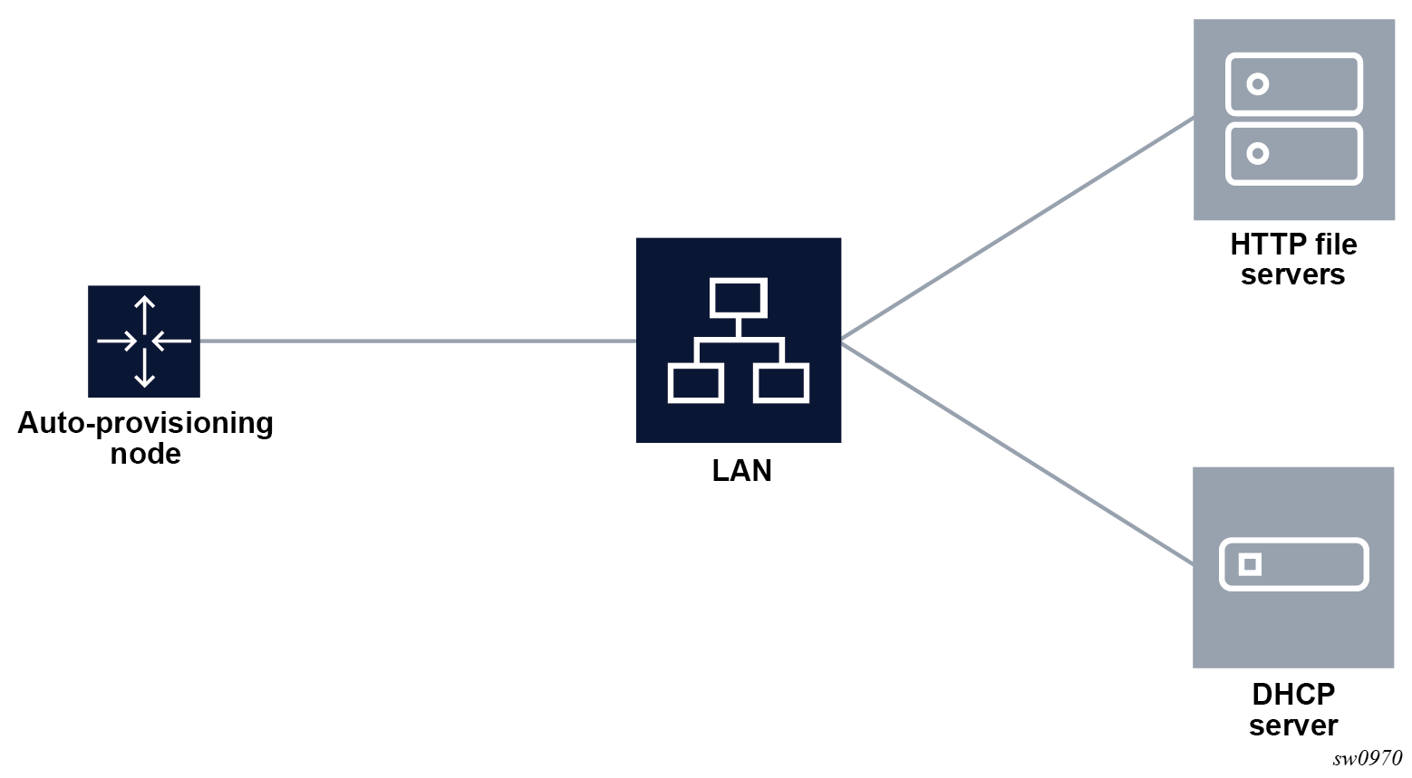
-
file servers and DHCP server in the same subnet, separate from the nodes
The following figure shows the scenario where only the file servers and DHCP server are in the same subnet. The DHCP relay is used to fill option 82 as the gateway address. The gateway address is used to find the appropriate pool in the DHCP server to assign the correct subnet IP address to the system.
Figure 3. Auto-provisioning with only file and DHCP servers in the same subnet 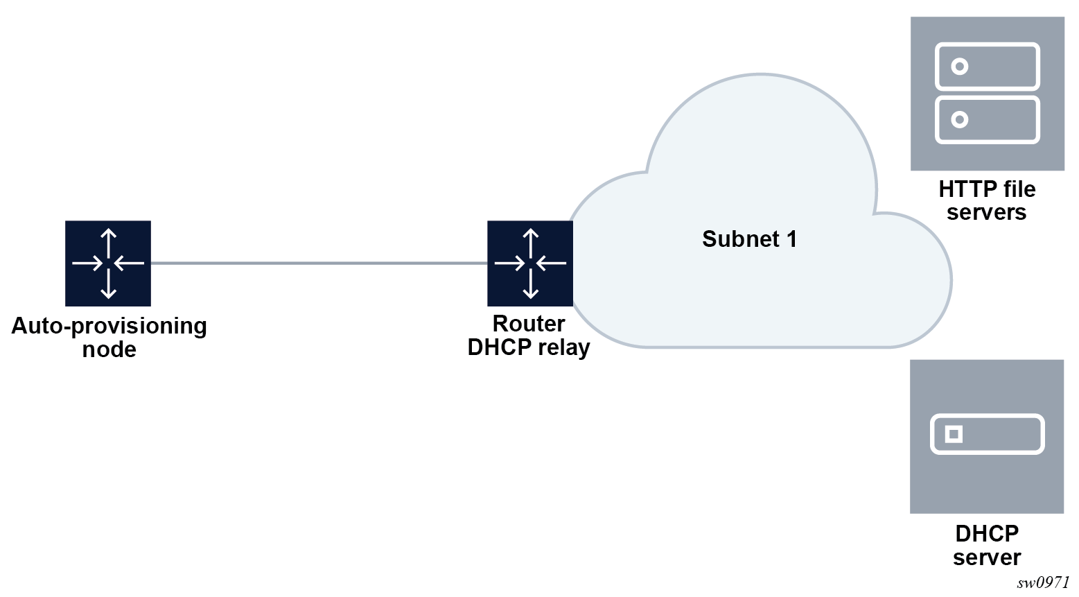
DHCP allows the Option 3 router to define the default gateway. If multiple addresses are provided using Option 3, the first address is used for the default gateway.
-
node, file servers, and DHCP server in different subnets
The following figure shows the scenario where all components are in different subnets. The DHCP relay adds the option 82 gateway address to the DHCP request, and the DHCP server adds the option 3 with the gateway address of the file server.
Figure 4. Auto-provisioning with all components in different subnets 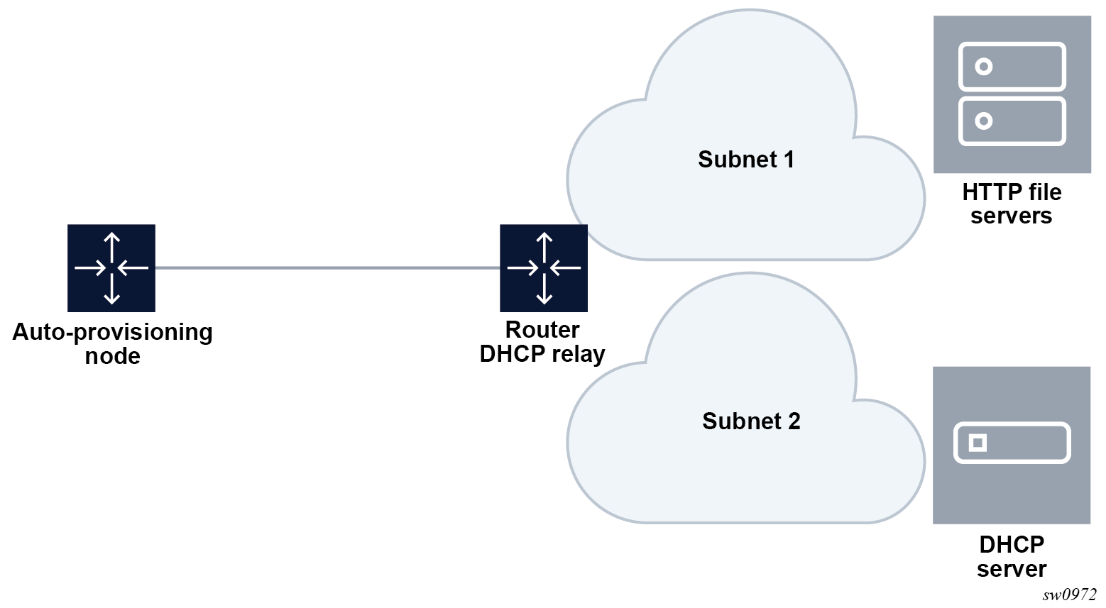
ZTP process overview
ZTP consists of the following processes:
Auto-boot process
In this process, the node discovers and provisions the chassis and installed cards.
The node is first connected to the network and powered on.
The node checks the first Ethernet port for a link.
The auto-boot process switches control to the auto-provisioning process.
See Auto-boot process details for more information about the auto-boot process.
Auto-provisioning process
In this process, the node detects operational ports, attempts to discover its IP address, and downloads the relevant files for provisioning.
The node sends a DHCP discovery request to the DHCP server using the out-of-band management port. If DHCP discovery is unsuccessful, the node reattempts it using the in-band management ports.
After DHCP discovery is successful, the DHCP server returns an IPv4 or IPv6 FTP or HTTP URL of a file server from which the node can retrieve provisioning information.
The node downloads the provisioning information and performs the auto-provisioning according to the specifications in the files.
After the node is successfully provisioned, it automatically reboots a final time and becomes operationally up.
See Provisioning files for more information about the auto-provisioning process.
The SR OS can also initiate the auto-provisioning process using a tools command.
Supported DHCP server options for ZTP
This section provides information about DHCP messages, DHCP clients, and DHCP servers that are supported by ZTP.
DHCP server offer options
Options 66, 67, and 43 are supported for indicating the location of the provisioning file. If both Options 66 and 67 are present in the DHCP offer, they take precedence over Option 43.
Option 66 contains the server URL or IP address, and Option 67 contains the URL of the provisioning file location.
Options 66 and 67 are meant for use by PXE TFTP, but are also used for HTTP and FTP. If an offer arrives with Options 66 and 67, Option 66 should resolve the server IP address and Option 67 should resolve the file location. Option 66 can be omitted by the provider, in which case Option 67 is used for both the server IP address and provider file URL. If an offer arrives with Option 67 only, it should resolve both the server IP address and file URL.
The auto-provisioning process distinguishes the host part of the URL and can resolve it using DHCP DNS.
Nokia-specific TLV
The Nokia-specific TLV is NOKIA-DCTOR-AUTOCONFIG. The location of the BOF for each system to use is configured in the optional autoboot file parameter, which is a standard Option 43 value initialized at the beginning of the process. The BOF location is sent in Option 43 as part of the DHCP offer and Ack messages from the DHCP server to the system. The system uses the location specified in Option 43 to initiate an FTP download of the BOF.
Supported DHCP client options for ZTP
The following table lists the supported DHCP client options for ZTP.
| Options | DHCP IPv4 option | IPv4 comments | DHCP IPv6 option | IPv6 comments |
|---|---|---|---|---|
Lease time |
Option 51 |
Always infinite |
— |
— |
|
Requested option list |
Option 55 |
— |
— |
— |
Client ID |
Option 61 |
Default is chassis serial ID |
Option 1 (DUID) |
Type 2 — vendor-assigned unique ID (default with chassis serial ID) Type 3 — link-layer address |
User class |
Option 77 |
‟platform;timos-release;ztp” |
Option 15 |
‟platform;timos-release;ztp” |
Class ID |
Option 60 |
‟NOKIA: FmtChassisType Strings” |
— |
— |
Supported DHCP server options for ZTP
The following table lists the supported DHCP server options for ZTP.
| Options | DHCP IPv4 option | IPv4 comments | DHCP IPv6 option | IPv6 comments |
|---|---|---|---|---|
|
Subnet mask |
Option 1 |
— |
— |
— |
|
Router |
Option 3 |
Default gateway |
— |
— |
|
DNS server |
Option 6 |
DNS server |
Option 23 |
DNS server |
| Syslog server | Option 7 |
Server IP address |
— |
— |
|
Lease time |
Option 51 |
Must be infinite |
— |
— |
|
Server address |
Option 54 |
Identifies the DHCP server |
— |
— |
|
Classless static route |
Option 121 |
Used to install static routes |
— |
— |
|
NTP server1 |
Option 42 |
— |
Option 56 |
— |
|
TFTP server name |
Option 66 |
Server IP address |
— |
— |
|
Bootfile name |
Option 67 |
URL of the file This option can be used without Option 66, in which case it contains the server name and the URL |
Option 59 |
Server name and URL of the file |
|
Vendor-specific options (See Nokia-specific TLV) |
Option 43 |
Nokia proprietary file location; can be used instead of Options 66 or 67, but Options 66 and 67 take precedence over Option 43 |
Option 17 |
Nokia proprietary file location; can be used instead of Option 59, but Option 59 takes precedence over Option 17 |
DHCP discovery and solicitation
IPv4 DHCP discovery and IPv6 DHCP solicitation are supported.
IPv4 DHCP discovery messages and IPv6 DHCP solicitation messages are sent from out-of-band and in-band management ports with active links. The first valid DHCP offer for the address family that arrives on the node is used.
In the BOF, the auto-boot option can be configured to send out IPv4, IPv6, or both IPv4 and IPv6 DHCP requests.
DHCP discovery (IPv4 and IPv6)
This section describes DHCP discovery options.
DHCP discovery Options 61 and 77
SR OS supports both Option 61 (client ID) and Option 77 (user class) DHCP discovery options.
Option 61 is used for DHCP server pool selection. Option 61 provides the client ID; the serial ID of the chassis with a type of 0 is used by default. This option is configurable using commands in the bof auto-boot context.
Option 77 provides the user class, describing what the device is and other information, such as the OS version. This option is set automatically, but can be removed using the BOF configuration. For example, the user can delete include-user-class in the BOF auto-boot configuration to avoid sending Option 77.
For ZTP, the DHCP discovery message should be sent with Option 77; the following information is automatically configured:
platform;timos-release;ztp
For auto-provisioning, Option 77 should use the following information:
platform;timos-release;AP
DHCP discovery Option 1 DUID (IPv6)
By default, the node uses RFC 3315 DUID Type 2 vendor-assigned unique IDs. The value for enterprise-id is 6527 and the identifier is the chassis serial number.
The option to use Type 3 is configured in the BOF. For MAC, the chassis MAC address is configured in a string format.
Type 1 is not supported.
DHCP solicitation (IPv6)
Unlike IPv4 DHCP offers, which contain the prefix and default route, IPv6 DHCP offers only contain the IP address assignment. The IPv6 route advertisement (RA) provides the default router and the prefix is set to /128 for the IP address supplied by the DHCP server.
For more information about RA support, see IPv6 DHCP/RA details. For more information about DHCP server offers, see DHCP server offer options.
IPv4 and IPv6 DHCP support
The ZTP process supports the use of IPv4 and IPv6 DHCP clients to obtain the provisioning file.
For ZTP processes, the node transmits both IPv4 and IPv6 discovery and solicitation messages. If offers arrive from both IPv4 and IPv6 servers, both offers are cached and the first offer received is processed. If the first offer does not fulfill the ZTP requirements and is rejected, the second offer is processed and accepted or rejected. If both offers received on an interface are rejected, ZTP goes to the next interface.
The provisioning file only allows file transfer in the address family of the DHCP offer that is used. If the offer is IPv4, the provisioning files are downloaded using IPv4. If the offer is IPv6, the provisioning files are downloaded using IPv6.
IPv4 route installation details
Option 3 (default route) and Option 121 (classless static route) are supported for IPv4 DHCP.
For identical routes with different next hops, only the first route is installed and the second route is kept as a backup route. ECMP is not supported.
There is no route limit for Option 121.
IPv6 DHCP/RA details
IPv6 DHCP offers do not contain an IP prefix. The IPv6 prefix is usually obtained from the IPv6 RA arriving from the upstream router. Because the SR OS router is the host for the ZTP process, the system assigns a /128 prefix to the IPv6 address obtained from the DHCP offer.
SR OS supports the use of an IPv6 RA to install IPv6 default and static routes from upstream routers. The system installs all the routes advertised using the RA. If the same route has been advertised from multiple upstream routers (next hops), the system installs the route with the highest preference. SR OS does not support ECMP if the same route is advertised from multiple next hops by multiple RAs.
In accordance with RFC 4861 recommendations, SR OS ensures that all RAs are obtained before the auto-provisioning process is started for IPv6. RFC 4861 recommends that the host (in this case, the SR OS router) send a minimum of three route solicitations to increase the likelihood of at least one route solicitation being received by the upstream routers. Each route solicitation is followed by a 4-second timeout, so the third route solicitation is sent 8 seconds after the first. The upstream routers must respond within 0.5 seconds. As a result, the SR OS router receives all RAs and routes within 8.5 seconds of the first route solicitation, and waits a maximum of 9 seconds to receive all RAs; ZTP always waits 20 seconds to receive all RAs, however, only the first RA received is used.
ZTP and DHCP timeouts
The ZTP timeout is user-configurable with a default value of 30 minutes. See Options and option modification and Configuring the ZTP timeout in the provisioning file for more information. After each ZTP timeout, the node reboots and reattempts the ZTP process. If the ZTP timeout interval expires while the node is executing a DHCP offer or downloading files, the node does not reboot. The DHCP offer is executed until it succeeds or fails, at which point the node reboots. If the offer is successful, the node comes up in normal operation mode.
The DHCP timeout interval is 20 seconds. If a DHCP offer is not received within the DHCP timeout interval, the auto-provisioning process is reattempted using the next valid interface.
ZTP procedure details
This section describes ZTP procedures including node bootup, BOF, auto-provisioning, logs, and events.
Node bootup
After the node is powered up, the BOF is examined for the auto-boot flag status. If the auto-boot flag is set in the bof.cfg file, the node goes into ZTP mode. If the auto-boot flag is not set in the bof.cfg file, the node continues booting normally.
If it is in ZTP mode, the node provisions all hardware necessary for the ZTP process. This includes the Ethernet ports. The node then checks for links on the Ethernet ports.
For more information about the BOF, see BOF.
Reinitiating ZTP during normal node bootup
ZTP can be reinitiated any time by setting the auto-boot flag and configuring the flag options in the BOF. After the auto-boot flag is set, any reboot forces the node into ZTP mode, including DHCP discovery, and downloading and reprocessing the provisioning file. The old BOF is kept in the storage medium until the ZTP process is successful, then the old BOF information is overwritten. If an unsuccessful ZTP process is interrupted and the auto-boot flag is removed, the node boots using the old BOF.
BOF
The auto-boot flag contains the following information:
client ID
The client ID is sent to the DHCP server to identify the chassis or node and to find a pool for the DHCP offer. If no client ID is configured, the chassis serial number is sent.
This option is used for both IPv4 client ID and IPv6 DUID Type 2.
port (port:vlan)
The port is used to send DHCP discovery; the port number must be configured manually in the BOF.
Auto-boot process details
This section describes the ZTP auto-boot process.
Options and option modification
By default, the auto-boot process scans all ZTP-enabled ports to find a port with an operational link. The scanned ports include:
out-of-band management port (Mgmt port)
-
Ethernet ports on the first two card or MDA slots (used for in-band management)
Note: For breakout connectors, only the first breakout port in the connector can be used for ZTP.
ZTP attempts to discover the node IP via DHCP and identifies the node using DHCP client ID Option 61 (IPv4) or Option 1 (IPv6). The client ID uses the chassis serial number by default. The chassis serial number is visible on the shipping box of the chassis.
Supported DHCP client options for ZTP lists the default DHCP client options for ZTP. Some client options can be manually configured in the BOF using the bof auto-boot command.
The optional auto-boot configuration options are as follows:
management port
Specify that ZTP should only be performed using the out-of-band management port (Mgmt port).
in-band VLAN
Specify ZTP should only be performed using Ethernet ports. The VLAN ID can be used to specify a VLAN to use for the auto-boot process.
IPv4, IPv6
client identifier
Identify the node to the DHCP server and find a pool for DHCP offers. This information is sent using Option 61 (IPv4) or Option 1 (IPv6). If the client-identifier options are not configured, the chassis serial number is sent by default. This option is used for both IPv4 client ID and IPv6 DUID Type 2.
include user class
Specify to include Option 77.
-
timeout
Specify in minutes the timeout for the ZTP process to be executed successfully before the node is rebooted and ZTP is retried because of an unsuccessful ZTP completion. The default ZTP timeout is 30 minutes.
See Configuring the ZTP timeout in the provisioning file for information about how to configure the ZTP timeout in a ZTP provisioning file.
The auto-boot options can be modified using the bof auto-boot command, or by interrupting the bootup process and manually modifying the bof.cfg file.
CLI access
The auto-boot process is executed in the background and does not block the CLI. The user can enter CLI commands while the auto-boot process runs in the background. A warning message is displayed to notify the user that the auto-boot process is being executed. Any configurations performed using the CLI may be lost when the node reboots following successful auto-boot and auto-provisioning processes. After the node has finished booting and if the auto-boot flag is set in the BOF, the node displays the login prompt.
The user can access the CLI using a console and can change and save the BOF configuration; as such, the user can remove or modify the auto-boot option in the BOF.
Interrupting auto-boot
The auto-boot process can be interrupted using the tools perform auto-boot terminate command. After the auto-boot process is terminated, use the bof auto-boot command to modify the auto-boot flag.
Auto-provisioning process
In this process, the node detects operational ports, attempts to discover its IP address, and downloads the relevant files for provisioning.
The node sends a DHCP discovery request to the DHCP server using the out-of-band management port. If DHCP discovery is unsuccessful, the node reattempts it using the in-band management ports.
After DHCP discovery is successful, the DHCP server returns an IPv4 or IPv6 FTP or HTTP URL of a file server from which the node can retrieve provisioning information.
The node downloads the provisioning information and performs the auto-provisioning according to the specifications in the files.
After the node is successfully provisioned, it automatically reboots a final time and becomes operationally up.
See Provisioning files for more information about the auto-provisioning process.
The SR OS can also initiate the auto-provisioning process using a tools command.
VLAN discovery
The node can perform VLAN discovery if it is shipped in ZTP mode. VLAN discovery is supported only for the in-band management port. It is not supported for the out-of-band management ports.
After the node is installed and powered up:
ZTP is attempted on the null (untagged) port first, including the out-of-band management port, and then on all in-band management ports with operational links.
-
SR OS scans each port with an operational link and sends IPv4 DHCP discovery messages.
-
SR OS waits for the DHCP offer within the DHCP timeout.
-
-
The first VLAN with a valid offer that includes the IPv4 DHCP Options 66 and 67, or Option 67 or 43, or IPv6 DHCP Option 59 or 17 is selected as the working VLAN and the ZTP process is executed on this VLAN.
Note: If there is no offer or the offer does not have the relevant or correct options, SR OS floods the network with DHCP discovery messages on all remaining non-reserved VLANs (1 to 4094). When a VLAN is discovered, the ZTP process is executed on the respective VLAN as described in the following sections.
Note: If there is no offer on any VLAN or the offer does not have the relevant or correct options, the node starts over from step 1.
By default, the auto-boot flag in the bof.cfg file has the VLAN discovery option enabled. The option can be disabled manually in the bof.cfg file or implicitly from the CLI BOF menu, using the command bof auto-boot inband. When the VLAN discovery option is disabled, the node executes the ZTP process using the untagged method only.
Auto-provisioning procedure
After the node enters ZTP mode, the auto-discovery process is executed to provision the necessary hardware for node discovery.
The following are the operational steps of the auto-discovery process.
DHCP is used to discover the IP address of the node.
Options 66 and 67, or Option 43 is used to find and download the provisioning file.
The provisioning file includes the location of necessary files, such as configuration information, system image, and licenses, along with the DNS needed to resolve these location URLs. The file also includes BOF information required to boot the node into operational mode.
The provisioning file is executed to download the named files to the node.
After all files are successfully downloaded, the node is rebooted and the auto-boot flag is cleared from the BOF.
After the node reboots, it comes up in normal operational mode.
The node can be put back into ZTP mode by editing the BOF to include the auto-boot flag and saving the BOF. Doing this causes the node to enter ZTP mode after it is rebooted.
Use one of the following methods to run the auto-provisioning process.
automatic execution
The auto-boot process automatically executes the auto-provisioning process if the auto-boot flag is set in the BOF.
manual execution
The auto-provisioning process can be executed manually using the following command.
tools perform system auto-node-provisioningIf the auto-provisioning process is executed manually, only interfaces without IP addresses are considered part of the discovery mechanism. Additionally, while the process is running, it attempts to discover DHCP servers using all card or MDA slots and ports with Layer 3 interfaces that do not have IP addresses.
Note: Using the following command while the auto-boot process is running is not allowed.tools perform system auto-node-provisioning
Provisioning files
Provisioning files are created by the user based on requirements and the locations of the necessary files. A provisioning file contains the locations and URLs of critical files such as the system image, configuration files, and necessary licenses, and can also contain DNS server information used to resolve these locations.
A provisioning file consists of two main parts:
locations of files
Contains locations of the following file types:
system image
configuration files
licenses
These items can be downloaded using HTTP, HTTPS, or FTP; DNS server information can also be included.
Note: If classic configuration mode is required when booting with ZTP, configuration files must have exit all as the first executable line.BOF information
Contains BOF information to be loaded on the node after the ZTP processes are completed; the BOF section of the file must be formatted correctly.
CAUTION: Ensure that the auto-boot flag is not set on the BOF that will be downloaded by the auto-provisioning process; failure to do so will cause the node to go back into ZTP mode after it reboots.The provisioning file is stored on the SD card and can be executed using the following command to re-download the named files:
tools perform system auto-node-provisioning file
Provisioning file download
The provisioning file location is discovered using DHCP offer Options 66 and 67 or Option 43, and is downloaded using HTTP or FTP.
The provisioning file URL can be resolved using DNS, in which case the IP addresses for up to three DNS servers should be present in the DHCP offer using Option 6 (IPv4) or Option 23 (IPv6). The DHCP DNS is only used for resolving the provisioning file URL, and not for resolving the URLs of the files named within the provisioning file.
ZTP does not support Option 15 domain names; the URL of the provisioning file should be in ‟host/domain” format, or a simple IP address should be used.
Provisioning file resolution using DNS
If the downloaded provisioning file includes a DNS IP in the DNS section of the file, the URLs of the files in the provisioning file must be resolved using this DNS server or the DNS server listed in the DHCP offer.
Up to three DNS addresses (primary, secondary, tertiary) can be listed in the DNS sections of the provisioning file. If all three DNS addresses are listed, they are attempted in the listing order to resolve the file URLs.
File download and redundancy
Up to three locations can be set for each file type, using the primary-url, secondary-url, and tertiary-url fields. The auto-provisioning process attempts to download all files using the primary-url information for each file. If this attempt is unsuccessful, the process reattempts using the secondary-url information for each file. If this attempt is not successful, the process reattempts using the tertiary-url information.
A ZTP operation is considered successful when all files named in the provisioning file are downloaded. If all file locations are attempted and all named files are not successfully downloaded, the auto-provisioning process fails and ZTP reattempts the provisioning process using the next valid interface.
Configuring the ZTP timeout in the provisioning file
The ZTP timeout is the total time allowed for the ZTP process to execute successfully. If the ZTP process fails to run successfully within the ZTP timeout duration, the node is rebooted and the ZTP process is retried. The default timeout is 30 minutes.
See Options and option modification for information about how to configure the ZTP timeout using CLI commands.
ZTP timeout information can be included in the provisioning file to configure a value different from the default. For a provisioning file example, see Example provisioning file.
set {
    timeout {
        hours 1
   }
}set {
timeout {
minutes 90
}
}Downloading the image file
The image file can be downloaded in the following ways:
- Extract the images from the OLCS CFLASH file and explicitly list them in the
provisioning file. Each of the .tim files is validated and the version of the
software is checked. The primary-trust-anchor is optional when the PKI and TLS
security artifacts are already downloaded and the provisioning file configures the
TLS client. The hash-value must be explicitly listed.
download { image "$(BOOT-PATH)/both.tim" { primary-url "$(FILESERVER)/both.tim" primary-trust-anchor "chassis_tls" verification { hash-algorithm sha256 hash-value "53473e2727caf55f3a38fa466622af2147762e26a8587e9248240a572cdee849" } } …….. } - Zip the image files and perform a single image download. ZTP can extract the images
and verify the .tim file and software version. An additional file can also be listed
for all files to be verified using sha256 or md5.
download {
  image "$(BOOT-PATH)/images.zip" {
      primary-url "$(FILESERVER)/images.zip"
      unzip
      verification {
          hash-algorithm sha256
          hash-value "53473e2727caf55f3a38fa466622af2147762e26a8587e9248240a572cdee849"
      }
  }
  # SHA-256 Checksum Files - File of a list of SHAR256 checksum values and file names (must be absolute)
  sha256 "$(BOOT-PATH)/somefile.txt" {
      primary-url "$(FILESERVER)/sha256-checksums.txt"
      verification {
          hash-algorithm sha256
          hash-value "53473e2727caf55f3a38fa466622af2147762e26a8587e9248240a572cdee849"
      }
  }
}
Example provisioning file
This section provides examples of provisioning file information. The example provisioning file is divided into multiple stages to demonstrate the device enrollment process through EST using customer-owned (cust) X.509 certificates. The process initializes the device with customer-owned security artifacts.
Multi-stage provisioning file
###############################
# STAGE 1 (Software Upgrade)
###############################
# Download new Software image
# ------------------------------
download {
  image "cf3:/images2/both.tim" {
     primary-url "https://88.88.4.1/images/sarhmc/both.tim"
     primary-trust-anchor "chassis_tls"
     verification {
        hash-algorithm sha256
        hash-value "e06538ebf127b698934db6df275f7ae4c17126b7307eeee121c9831cd5efd258"
     }
     match-or-replace
  }
  image "cf3:/images2/kernel.tim" {
     primary-url "https://88.88.4.1/images/images/sarhmc/kernel.tim"
     primary-trust-anchor "chassis_tls"
     verification {
        hash-algorithm sha256
        hash-value "697527e98938ad5c76c795686021bc196b338c32337833fc57a664f6fb404fe4"
     }
     match-or-replace
  }
  image "cf3:/images2/support.tim" {
     primary-url "https://88.88.4.1/images/sarhmc/support.tim"
     primary-trust-anchor "chassis_tls"
     verification {
        hash-algorithm sha256
        hash-value "f6f89df550e3c3db1f70f462678349eb40e0e99c5df4a8619b8b7b41bf9a31d9"
     }
     match-or-replace
  }
}
# Update BOF to perform SW Upgrade
bof {
   primary-image    cf3:/images2/
   primary-config   cf3:/site-abcd.cfg
   wait             3
   persist          off
   auto-boot
}
# ++++++++++++++++++++++++
# ****SYSTEM REBOOTS******
# ++++++++++++++++++++++++
# SW Upgrade Complete. Remove old Image to make
# space for firmware
execute {
  file delete cf3:/images1/* force
}
# Move on to STAGE 2 - Firmware Upgrade
# (note next-provisioning-file checks active SW and reboots if needed)
next-provisioning-file cf3:\STAGE2.ztp
###############################
# STAGE 2 (Firmware Upgrade)
###############################
# Initialize cell port and download (on Eth) cellular firmware for update
# Target carrier config: Generic-PTCRB (version Generic-PTCRB 49.00.001 M0V.060001 P0V.071603)
# ZTP skips download/reboot when installed FW already matches version
#
write "cf3:/STAGE2.ZTP" {
cellular {
    carrier "Generic-PTCRB"
    # clear MDA occurs when setting carrier
    pdn-profile {
         apn "internet"
         protocol ipv6
    }
    firmware-upgrade {
        # what is displayed in show port 1/1/1 for firmware
        version "Generic-PTCRB 49.00.001 M0V.060001 P0V.071603"
        file "cf3:/FN920C04-WW_49.00.001_CUST_071603_H1S0_SIGNED_TFL.zip" {
            primary-url "http://88.88.4.1/images/sarhmc/cellular/firmwareFiles/FN920C04-WW_49.00.001_CUST_071603_H1S0_SIGNED_TFL.zip"
            verification {
                hash-algorithm sha256
                hash-value "e2f096f234a1e49afca92cabff58c24789c584c54b4b69a471bad28082af66a9"
            }
        }
    }
    # firmware is updated upon next reboot during provisioning
}
#################################
# STAGE 2b (certificate download)
#################################
download {
  # device's Root CA
  file "cf3:/custRootCA.pem" {
     primary-url "http://88.88.4.1/certs/custRootCA.pem"
     verification {
        hash-algorithm sha256
        hash-value "f6f5319b8dc83f9eb1da292ffcbefbbff068ae9a67ffc8a3f366d211774b4de5"
     }
  }
  # device's intermediary CA
  file "cf3:/custIntermediaryCA.pem" {
     primary-url "http://88.88.4.1/certs/custIntermediaryCA.pem"
     verification {
        hash-algorithm sha256
        hash-value "e0787cbe981fe8a69c9dae3928a6e79f4362e912960a8ff85fdcc817b271b8b3"
     }
  }
  # CRL for root CA
  file "cf3:/custRootCA.crl" {
     primary-url "http://88.88.4.1/certs/custRootCA.crl"
     verification {
        hash-algorithm sha256
        hash-value "e85985f695eea8408b6f27cca78cddfadf57fbd15fb7313a6f1d28c7f346d4ea"
     }
  }
  # CRL for intermediary CA
  file "cf3:/custIntermediaryCA.crl" {
     primary-url "http://88.88.4.1/certs/custIntermediaryCA.crl"
     verification {
        hash-algorithm sha256
        hash-value "17649d2c2d683d1e92da1ada6881d91b649d158fd028e45f78bda3b44e0c7695"
     }
  }
  #
  # (optional) Download server (trust anchor) CA certs and CRLs
  #----------------------------------------------------------
  # server Root CA
  file "cf3:/serverRootCA.pem" {
     primary-url "http://88.88.4.1/certs/serverRootCA.pem"
     verification {
        hash-algorithm sha256
        hash-value "f6f5319b8dc83f9eb1da292ffcbefbbff068ae9a67ffc8a3f366d211774b4de5"
     }
  }
  # server intermediary CA
  file "cf3:/serverIntermediaryCA.pem" {
     primary-url "http://88.88.4.1/certs/serverIntermediaryCA.pem"
     verification {
        hash-algorithm sha256
        hash-value "e0787cbe981fe8a69c9dae3928a6e79f4362e912960a8ff85fdcc817b271b8b3"
     }
  }
  # server Root CA CRL
  file "cf3:/serverRootCA.crl" {
     primary-url "http://88.88.4.1/certs/serverRootCA.crl"
     verification {
        hash-algorithm sha256
        hash-value "e85985f695eea8408b6f27cca78cddfadf57fbd15fb7313a6f1d28c7f346d4ea"
     }
  }
  # server intermediary CA CRL
  file "cf3:/serverIntermediaryCA.crl" {
     primary-url "http://88.88.4.1/certs/serverIntermediaryCA.crl"
     verification {
        hash-algorithm sha256
        hash-value "17649d2c2d683d1e92da1ada6881d91b649d158fd028e45f78bda3b44e0c7695"
     }
  }
}
# Move on to STAGE 3 - EST enroll over LTE
next-provisioning-file cf3:\STAGE3.ztp
}

write "cf3:/STAGE3.ZTP" {
###############################
# STAGE 3 (EST Enrollment)
###############################
execute {
  exit all
  config
    router Base
        static-route-entry ::/0 next-hop pdn1-sim1 no shutdown
    exit
    system
        file-transmission-profile "chassis_ftp" create
            no ipv4-source-address
            no ipv6-source-address
            redirection 8
            retry 100
            timeout 120
        exit
        security
            pki
                est-profile "cust_chassis_enroll" create
                    client-tls-profile "customer_tls"
                    server 2002:468:2000:2:80:10:1:142 port 8085
                    http-auth username estuser password estpwd
                    transmission-profile "chassis_ftp"
                exit
            exit
        exit
    exit
  exit

  admin certificate gen-keypair cf3:/custchassis.key curve secp384r1
  admin certificate import type key input cf3:/custchassis.key output custchassis.key format der
  admin certificate import type cert format pem input cf3:/custRootCA.pem output custRootCA.cert
  admin certificate import type crl input cf3:/custRootCA.crl output custRootCA.crl format pem
  admin certificate import type cert format pem input cf3:/custIntermediaryCA.pem output custIntermediaryCA.cert
  admin certificate import type crl input cf3:/custIntermediaryCA.crl output custIntermediaryCA.crl format pem
  admin certificate import type cert format pem input cf3:/serverRootCA.pem output serverRootCA.cert
  admin certificate import type crl input cf3:/serverRootCA.crl output serverRootCA.crl format pem
  admin certificate import type cert format pem input cf3:/serverIntermediaryCA.pem output serverIntermediaryCA.cert
  admin certificate import type crl input cf3:/serverIntermediaryCA.crl output serverIntermediaryCA.crl format pem
  config
    system
        security
            pki
                ca-profile "serverRootCA" create
                    cert-file "serverRootCA.cert"
                    crl-file "serverRootCA.crl"
                    no shutdown
                    exit
                ca-profile "serverIntermediaryCA" create
                    cert-file "serverIntermediaryCA.cert"
                    crl-file "serverIntermediaryCA.crl"
                    no shutdown
                    exit
                exit
            tls
                trust-anchor-profile "chassis_est_ta" create
                    trust-anchor "serverRootCA"
                    trust-anchor "serverIntermediaryCA"
                exit
                client-cipher-list "customer_ciphers" create
                    cipher 1 name tls-rsa-with-aes256-cbc-sha256
                    cipher 2 name tls-rsa-with-aes256-gcm-sha384
                    cipher 3 name tls-ecdhe-rsa-aes128-gcm-sha256
                    cipher 4 name tls-ecdhe-rsa-aes256-gcm-sha384
                    cipher 5 name tls-ecdhe-ecdsa-aes128-gcm-sha256
                    cipher 6 name tls-ecdhe-ecdsa-aes256-gcm-sha384
                exit
                client-tls-profile "customer_tls" create
                    trust-anchor-profile "chassis_est_ta"
                    cipher-list "customer_ciphers"
                    no shutdown
                exit
            exit
        exit
    exit
  exit
  admin certificate est enroll est-profile cust_chassis_enroll key cf3:/system-pki/custchassis.key output custchassis.cert hash-alg sha512 subject-dn C=EU,O=Customer,CN=NS1234567890 validate-cert-chain force
  config
    system
        security
            pki
                ca-profile "custRootCA" create
                    cert-file "custRootCA.cert"
                    crl-file "custRootCA.crl"
                    no shutdown
                    exit
                ca-profile "custIntermediaryCA" create
                    cert-file "custIntermediaryCA.cert"
                    crl-file "custIntermediaryCA.crl"
                    no shutdown
                    exit
                exit
            tls
                cert-profile "customer_est_cert" create
                    entry 1 create
                        cert "custchassis.cert"
                        key "custchassis.key"
                        send-chain ca-profile "custRootCA"
                        send-chain ca-profile "custIntermediaryCA"
                    exit
                    no shutdown
                exit
             exit
         exit
     exit
  exit
  #
  # chassis_tls from conveyed STAGE0 remains for bootstrap STAGE1 SW download.
  #
  file delete cf3:/custchassis.key force
  file delete cf3:/custRootCA.pem force
  file delete cf3:/custRootCA.crl force
  file delete cf3:/custIntermediaryCA.pem force
  file delete cf3:/custIntermediaryCA.crl force
  file delete cf3:/serverRootCA.pem force
  file delete cf3:/serverRootCA.crl force
  file delete cf3:/serverIntermediaryCA.pem force
  file delete cf3:/serverIntermediaryCA.crl force
}
#Move on to STAGE 4 - Configuration Download.
next-provisioning-file cf3:STAGE4.ztp
}
###############################
# STAGE 4 (Finalize System)
###############################
# STAGE4 HTTPS uses customer_tls (trust-anchor); will not attach
# customer_est_cert here.
#
write "cf3:/STAGE4.ZTP" {
# Download Final Configuration.
download {
  config "cf3:/custConfig.cfg" {
     primary-url "https://[2002:468:2000:2:80:10:1:142]/config/custConfig.cfg"
     primary-trust-anchor "customer_tls"
     verification {
        hash-algorithm sha256
        hash-value "8949bd0c96f12c72898ba5ed26453feeace9efd5126ceb4f3b57753dbf7fa219"
     }
  }
}
bof {
   primary-image    cf3:/images2
   primary-config   cf3:/custConfig.cfg
   wait             3
   persist          off
}
}
For an HTTPS URL, the trust anchor needs to be referenced in the provisioning file. The trust anchor name references the entry in the import trust-anchor section of the file. The provisioning file can also specify the TLS version to use for HTTPS. If the TLS version is not specified, “all” will be considered as the default.
The following example shows a provisioning file with three trust anchors, TRUST_ANCHOR_12,
TRUST_ANCHOR_13, and TRUST_ANCHOR_ALL. Each anchor includes the tls-version
which enforces the use of TLS 1.2, 1.3, or both, respectively. A different configuration
download is bound to each anchor.
Trust anchors for HTTPS URL in provisioning file
import {
    trust-anchor TRUST_ANCHOR_12 {
        cert "cf3:/ca12.crt" {
            format pem
            tls-version "1.2"
            primary-url ftp://user-name:password@10.10.10.66//fileserver-1/ca12.crt
        }
        crl "cf3:/ca12.crl" {
            format der
            primary-url ftp://user-name:password@10.10.10.66//fileserver-1/ca12.crl
        }
    }
    trust-anchor TRUST_ANCHOR_13 {
        cert "cf3:/ca13.crt" {
            format pem
            tls-version "1.3"
            primary-url ftp://user-name:password@10.10.10.66//fileserver-1/ca13.crt
        }
        crl "cf3:/ca13.crl" {
            format der
            primary-url ftp://user-name:password@10.10.10.66//fileserver-1/ca13.crl
        }
    }
    trust-anchor TRUST_ANCHOR_ALL {
        cert "cf3:/ca-all.crt" {
            format pem
            tls-version "all"
            primary-url ftp://user-name:password@10.10.10.66//fileserver-1/ca-all.crt
        }
        crl "cf3:/ca-all.crl" {
            format der
            primary-url ftp://user-name:password@10.10.10.66//fileserver-1/ca-all.crl
        }
    }
}
download {
    config "cf3:/ztp/ztp_dut-a.cfg.12" {
        primary-url https://10.10.10.64:81/ztp_dut-a.cfg
        primary-trust-anchor "TRUST_ANCHOR_12"
    }
    config "cf3:/ztp/ztp_dut-a.cfg.13" {
        primary-url https://10.10.10.64:81/ztp_dut-a.cfg
        primary-trust-anchor "TRUST_ANCHOR_13"
    }
    config "cf3:/ztp/ztp_dut-a.cfg.all" {
        primary-url https://10.10.10.64:81/ztp_dut-a.cfg
        primary-trust-anchor "TRUST_ANCHOR_ALL"
    }
}
Proxy support
HTTP and HTTPS can connect to public servers using a proxy. The proxy is in URL format and the URL must be resolved using the provisioning file DNS.
The proxy can include a username and password. Proxy Auto-Configuration (PAC) is not supported.
Proxy information formatting is as follows:
http://user@hostname:file-path
https://user@hostname:file-path
proxy http://ip-or-url user@hostname:port
The HTTP (or HTTPS) proxy support information is included in file commands and in the ZTP provisioning file. The following example shows HTTP proxy information in the provisioning file.
image "cf3:/both.tim" {
    primary-url "http://200.150.40.140:81/both.tim"
    secondary-url "http://200.150.40.140:81/both.tim"
    tertiary-url "http://200.150.40.140:81/both.tim"
    primary-proxy http://132.2.3.1:8080
    secondary-proxy http://133.3.4.1:8080
  }
Day 0 configuration
To improve initial router functionality and reuse information discovered by ZTP in the configuration file, the user can include an optional day 0 configuration template within the provisioning file. This day 0 configuration template can obtain configuration details for specific modules that can be used to provision the node and establish node connectivity. Predefined symbols are used to add parameters discovered by ZTP, such as the port and VLAN, to the configuration template.
Any supported configuration can be included in the day 0 configuration template, including configuration of port types and services. However, Nokia recommends that day 0 configuration details should be kept to the minimum necessary to ensure that basic network connectivity is available for the ZTP process to run and complete.
When the provisioning file is received through the ZTP process, the day 0 configuration template
section of the provisioning file is converted to a configuration file, as specified by the
Write
				cf3:/configuration-file-name.cfg
entry within the template. The
BOF section of the provisioning file must specify the configuration file generated from the
day 0 configuration template using the primary-config
cf3:/configuration-file-name.cfg entry.
Some unknown elements within the day 0 configuration template can be entered as symbols, which are then converted to discovered information as the node is provisioned; see Day 0 symbols.
See Sample day 0 configuration template for a configuration example, including the day 0 configuration template and associated BOF section of the provisioning file.
Day 0 symbols
Use symbols to generalize and reuse a single provisioning file across multiple ZTP deployments and for value substitutions and conditions in the day 0 configuration template of the provisioning files. The same symbol can appear as many times as required and can be used for both conditional statements and substitutions.
Symbol use for substitution
A day 0 configuration template can include symbols that are replaced with discovered
information when the day 0 configuration is implemented. Symbols for substitution must
be entered using the format $(<symbol-name>). The
following example shows a supported use case of a symbol for substitution.
card $(ztp.bootstrap.slot)
    card-type $(ztp.bootstrap.card-type)
        mda $(ztp.bootstrap.mda)
            mda-type $(ztp.bootstrap.mda-type)
    exit
exit
Symbol use for conditions
A day 0 configuration template can include symbols that are replaced with discovered
information when the day 0 configuration is implemented. Symbols for conditions must be
entered using the format @(<symbol-name>) at the
beginning of a line. If the condition is not met (that is, the symbol does not exist),
the rest of the line is skipped and not written into the day 0 configuration file on the
compact flash. The following example shows a supported use case of a symbol for
conditions.
@(ztp.uplink.connector)    port (ztp.uplink.connector)
@(ztp.uplink.connector)    connector
@(ztp.uplink.connector)    breakout $(ztp.uplink.breakout)
@(ztp.uplink.connector)    exit
@(ztp.uplink.connector)    exit
Supported symbols
The following table describes the supported symbols for a day 0 configuration template.
| Symbol name | Description | Example value | Conditional | Discovered |
|---|---|---|---|---|
| sys.platform | Platform name |
"7750" |
No. Always available. | Configured for the system and is exposed at system boot-up |
| sys.type | Chassis type |
"SAR-7" |
No. Always available. | Configured for the system and is exposed at system bootup |
| sys.serial-number | Serial number of the chassis | “NS1234567” | No. Always available. | Configured for the system and is exposed at system bootup |
| sys.mac-address | Base chassis MAC of chassis | “01:01:01:01:01:01” | No. Always available. | Configured for the system and is exposed at system bootup |
| sys.sw-version | Software version | "TiMOS-B-23.10.R2" | No. Always available. | Configured for the system and is exposed at system boot-up |
| ztp.bootstrap.uplink | Full uplink used for bootstrap (including VLAN). Intended to be used as interface port binding in the day 0 configuration. |
“1/1/1” “1/1/1:1000” “A/1” |
No. Always available. | Discovered at VLAN discover or ZTP discovery time |
| ztp.bootstrap.uplink.card-type | Card-type of uplink slot used for bootstrap | “xcm-1s” | Yes. Available when uplink is inband. | Discovered at VLAN discover or ZTP discovery time |
| ztp.bootstrap.uplink.slot | Slot of uplink used for bootstrap | “1” | Yes. Available when uplink is inband. | Discovered at VLAN discover or ZTP discovery time |
| ztp.uplink.xiom | Xiom identifier of uplink used for bootstrap | “x1” | Yes. Available when uplink is inband and has an xiom. | Discovered at VLAN discover or ZTP discovery time |
| ztp.uplink.xiom-type | Xiom-type of xiom used for bootstrap | “Iom2-se-6.0t” | Yes. Available when uplink is inband and has an xiom. | Discovered at VLAN discover or ZTP discovery time |
| ztp.uplink.mda | The MDA number of the MDA used for bootstrap (This will either be the MDA under card or MDA under xiom if uplink has xiom) | “1” | Yes. Available when uplink is inband. | Discovered at VLAN discover or ZTP discovery time |
| ztp.uplink.mda-type | The MDA type of the MDA used for bootstrap (This will either be the MDA under card or MDA under xiom if uplink has xiom) | “m4-sfp” | Yes. Available when uplink is inband. | Discovered at VLAN discover or ZTP discovery time |
| ztp.bootstrap.uplink.port | Uplink port without encapsulation value (VLAN) | 1/2/c1/1 | No. Always available. | Discovered at VLAN discover or ZTP discovery time |
| ztp.bootstrap.uplink.vlan | Uplink VLAN (encapsulation value) | “1000” | Yes. Available when uplink has a vlan. | Discovered at VLAN discover or ZTP discovery time |
| ztp.bootstrap.connector | Uplink connector ID | 1/1/c1 | Yes. Available when uplink is a connector-port. | Discovered at VLAN discover or ZTP discovery time |
| ztp.bootstrap.breakout | Connector breakout type | c1-10g | Yes. Available when uplink is a connector port. | Discovered at VLAN discover or ZTP discovery time |
| ztp.bootstrap.rs-fec | Connector RS-FEC mode setting | Yes. If connector has a non-default rs-fec mode setting. | Discovered at VLAN discover or ZTP discovery time | |
| ztp.bootstrap.uplink.rs-fec | Uplink port RS-FEC mode setting | Yes. If uplink port has a non-default rs-fec mode setting. | Discovered at VLAN discover or ZTP discovery time | |
| ztp.bootstrap.uplink.speed | Uplink port speed setting | Yes. If uplink port has a non-default speed setting | Discovered at VLAN discover or ZTP discovery time | |
| Ztp.bootstrap.ip | IP address used during bootstrap (IPv4 or IPv6) |
1.2.3.4 1::344:2 |
No. Always available. | Discovered via DHCP offer |
| Ztp.bootstrap.prefixlen | The prefix length of the IP address used under interface during bootstrap | No. Always available. | Discovered via DHCP offer |
Sample day 0 configuration template
The following is a sample of a day 0 configuration template included in a provisioning file.
# Generate Day-0 Configuration
# ----------------------------
Write "cf3:/config-template.cfg" {
#########################
# !!DAY0 CONFIG START!! #
#########################
exit all
configure
#--------------------------------------------------
echo "System Configuration"
#--------------------------------------------------
    system
        name "chassis-name"
        snmp
        exit
        login-control
            idle-timeout disable
        exit
        time
            ntp
                server 192.168.194.202
                no shutdown
            exit
        exit
        thresholds
            rmon
            exit
        exit
    exit
#--------------------------------------------------
echo "System Security Configuration"
#--------------------------------------------------
    system
        security
            telnet-server
            ftp-server
            snmp
                community "private" rwa version both
                community "public" r version both
            exit
        exit
    exit
#--------------------------------------------------
echo "Log Configuration"
#--------------------------------------------------
    log
        snmp-trap-group 90
            trap-target ‟”
        exit
        log-id 90
            from main change
            to snmp
        exit
    exit
exit all
configure
    router
#--------------------------------------------------
echo "IP Configuration"
#--------------------------------------------------
        interface "1/2/1"
            port $(ztp.bootstrap.uplink)
            address 192.168.0.1/31
            ipv6
            exit
            no shutdown
        exit
    exit
exit all
#########################
# !!DAY0 CONFIG END!!   #
#########################
}
# Generate New BOF File
# ---------------------
bof {
  primary-image  cf3:/image.both
  primary-config cf3:/config-template.cfg
  autonegotiate
  duplex full
  speed 100
  wait 3
  persist off
  console-speed 115200
}
Basic system management
For general information about basic system management support, see the following topics in the 7450 ESS, 7750 SR, 7950 XRS, and VSR Basic System Configuration Guide, "System management":
-
System management commands
-
System information
-
System time
-
Time zones
-
NTP
-
-
-
Administrative tasks
-
Saving configurations
-
Specifying post-boot configuration files
-
-
System router instances
-
System configuration process overview
-
General configuration notes
-
Configuring system management features
-
Basic system configuration
-
Common configuration tasks
BOF and configuration file encryption
The 7705 SAR-Hm series of routers provides operators the option to encrypt the BOF and configuration files. For information, see the 7450 ESS, 7750 SR, 7950 XRS, and VSR Basic System Configuration Guide, "BOF and configuration file encryption".
Network Services Platform functional overview
The Nokia Network Services Platform (NSP) is a group of interoperating network management modules that provide comprehensive end-to-end management of a wide range of network domains and topologies.
The Nokia NSP Network Functions Manager - Packet (NSP NFM-P) is used to discover, configure, and manage the nodes and related cellular domains. The NSP NFM-P provides the following specific functions. (See the NSP NFM-P User Guide for more information.)
creates and manages the cellular domains. A cellular domain is a group of nodes where each node in the group connects to the same head-end nodes, shares the same deployment modes of operation, and is part of the same NGE domain. For more information about deployment modes of operation, see the PDN router interfaces section of this guide.
drives the ADP-Hm process for each new node to be discovered in a cellular domain. For static cellular interface IP and dynamic modes of operation, the NSP NFM-P creates a management VPRN service for in-band management of each node.
manually adds or removes nodes to and from cellular domains
supports the XML input lists of the SIM IMSI values that are expected to participate in the cellular domain and initiate the ADP-Hm process within the cellular domain. These lists include the SIM information and optionally, the system IP for node boot-strap process.
creates a security association between the SIM, IMEI, and the chassis identifier for each node being managed such that unexpected changes are flagged as potential security violations to the operator.
supports a configurable NSP NFM-P polling interval for nodes. Configurable polling is intended to minimize traffic between the NSP NFM-P and a large-scale deployment of nodes. To that end, the NSP NFM-P also polls the status of the BGP sessions between head-end nodes and the nodes in the cellular domain in order to monitor the reachability and status of the nodes in the cellular domain.
Debug commands
The 7705 SAR-Hm series of routers supports debug commands that enable detailed debug information for various protocols.
Debug output is generally displayed by configuring a log using from debug-trace.
The currently enabled debug can be seen using the show debug command.
A debug configuration does not persist when the router reboots. The admin debug-save command can be used to save the debug configuration. The resulting file can be exec'ed later as needed.
Individual debug commands are described in the 7450 ESS, 7750 SR, 7950 XRS, and VSR Classic CLI Command Reference Guide.
Tools commands
The 7705 SAR-Hm series of routers supports tools commands. The tools commands provide two primary functions: dump and perform.
The tools dump commands are used to provide additional detailed and enhanced information about various aspects of the router.
The tools perform commands provide the ability to trigger a variety of actions on the router.
Individual tools commands are described in the 7450 ESS, 7750 SR, 7950 XRS, and VSR Clear, Monitor, Show, and Tools CLI Command Reference Guide.