OAM and SAA
This chapter provides information about the Operations, Administration, and Maintenance (OAM) and Service Assurance Agent (SAA) commands available in the CLI for troubleshooting services.
Topics in this chapter include:
OAM Overview
Delivery of services requires that a number of operations occur properly and at different levels in the service delivery model. For example, operations—such as the association of packets to a service, VC labels to a service, and each service to a service tunnel—must be performed properly in the forwarding plane for the service to function properly. In order to verify that a service is operational, a set of in-band, packet-based OAM tools is provided, with the ability to test each of the individual packet operations.
For in-band testing, the OAM packets closely resemble customer packets in order to effectively test the customer's forwarding path, but they are distinguishable from customer packets so that they can be kept within the service provider's network and not get forwarded to the customer.
The suite of OAM diagnostics supplements the basic IP ping and traceroute operations with diagnostics specialized for the different levels in the service delivery model. In addition, there are diagnostics for MPLS LSPs, SDPs, and Services within a service.
This section describes the following topics:
ICMP and ICMPv6 Diagnostics
Internet Control Message Protocol (ICMP) is part of the IP suite as defined in RFC 792, Internet Control Message Protocol, for IPv4 and RFC 4443, Internet Control Message Protocol (ICMPv6) for the Internet Protocol Version 6 (IPv6) Specification.
ICMP and ICMPv6 send and receive control and error messages used to manage the behavior of the TCP/IP stack. ICMP and ICMPv6 provide:
debugging tools and error reporting mechanisms to assist in troubleshooting an IP network
the ability to send and receive error and control messages to far-end IP entities
Ping
Ping is used to determine if there is IP layer connectivity between the 7705 SAR and another node in the network.
The 7705 SAR supports redirection of SGT to egress data queues instead of the default control queue. To redirect ping to a data queue, the ping command includes the fc-queue option, which specifies the queue to be used for servicing the ping packets in the egress direction. All other SGT applications are redirected using the config>router>sgt-qos>application>fc-queue or config>service>vprn>sgt-qos>application>fc-queue command. For more information about SGT redirection, see the 7705 SAR Quality of Service Guide, "SGT Redirection".
Traceroute
Traceroute is used to determine the path that an IP packet takes from the 7705 SAR to a specified router.
Two-Way Active Measurement Protocol
The Two-way active measurement protocol (TWAMP) provides a standards-based method to measure the round-trip performance (including the packet loss, delay, and jitter) of IP packets that are transmitted between two devices. TWAMP, which is described in RFC 5357, uses the methodology and architecture of the One-way active measurement protocol (OWAMP) to assess the two-way transmission of IP packets.
TWAMP offers advantages for performance monitoring at Layer 3/IP because it provides functions that other performance monitoring methods, such as ICMP, lack:
timestamping for delay and jitter measurements
high-accuracy timestamping at Tx and Rx on 7705 SAR nodes for error-free results
intelligent control plane
There are four logical entities in TWAMP:
control client—initiates the TWAMP control session and negotiates the security protocols to be used and the tests to be performed with the server
server—negotiates with the control client request to establish the control session
session sender—transmits test packets to the session reflector
session reflector—transmits a packet to the session sender in response to each packet it receives
The TWAMP control and data (test) protocol operate on separate planes, as shown in TWAMP Logical Entities (RFC 5357). The TWAMP control protocol initiates test sessions and starts and stops the tests. The TWAMP test protocol exchanges test packets between TWAMP entities.
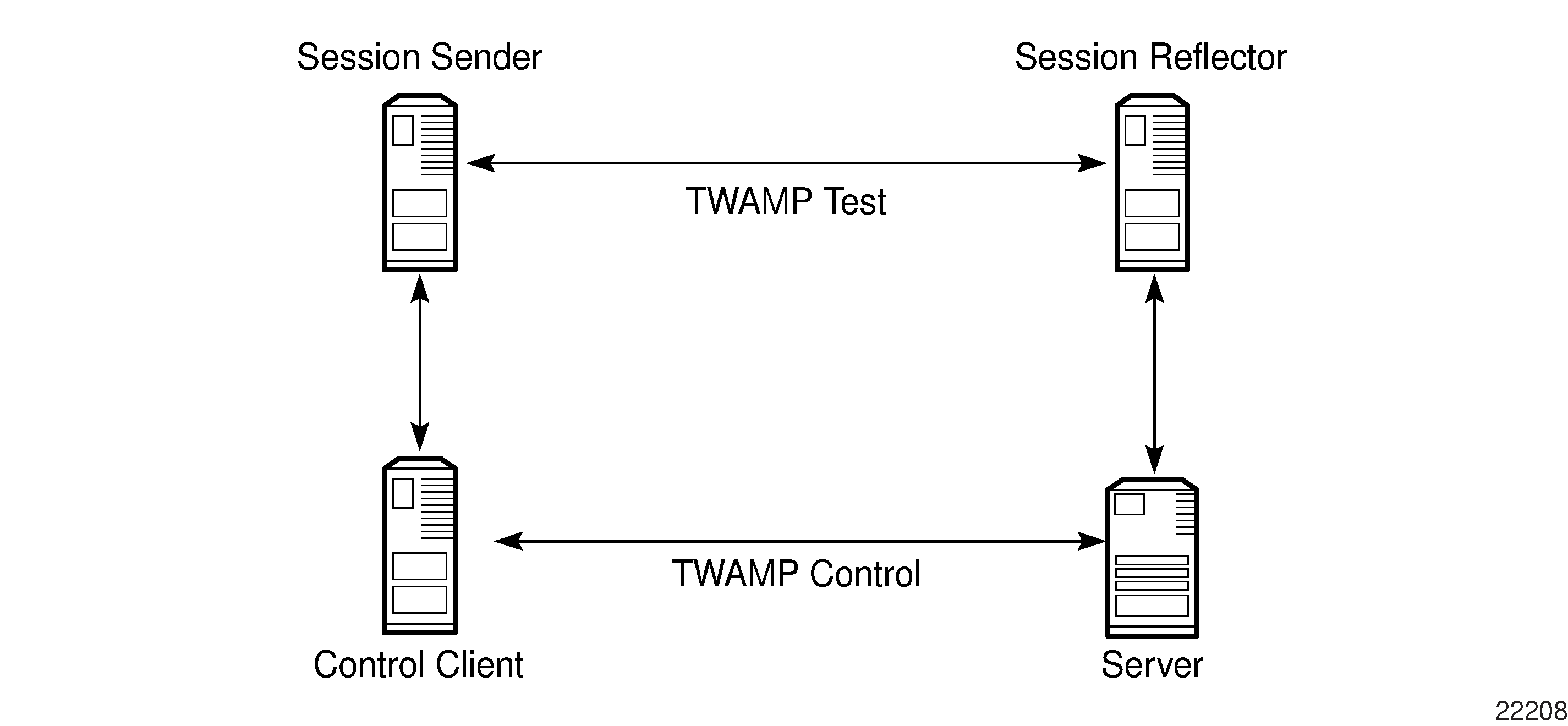
The control client and session sender are typically implemented in one physical device (also known as the client device) and the server and session reflector are typically implemented in a second physical device (also known as the server device), as shown in Typical TWAMP Implementation.

The control client and server establish a TCP connection and exchange TWAMP control messages over the connection. To start the test, the client communicates the test parameters to the server. If the server agrees to conduct the test, the test begins as soon as the client sends a start-sessions message. As part of a test, the session sender sends a stream of UDP-based test packets to the session reflector. The session reflector responds to each received packet with a UDP-based packet response. When the session sender receives the response packets from the session reflector, the information is used to calculate two-way delay, packet loss, and packet delay variation between the two devices.
The following ports are assigned for the TWAMP control protocol, as defined in RFC 5357:
862/tcp
862/udp
7705 SAR Support for TWAMP Server
The 7705 SAR supports the TWAMP server and the session reflector functions, as shown in 7705 SAR as TWAMP Server and Session Reflector.
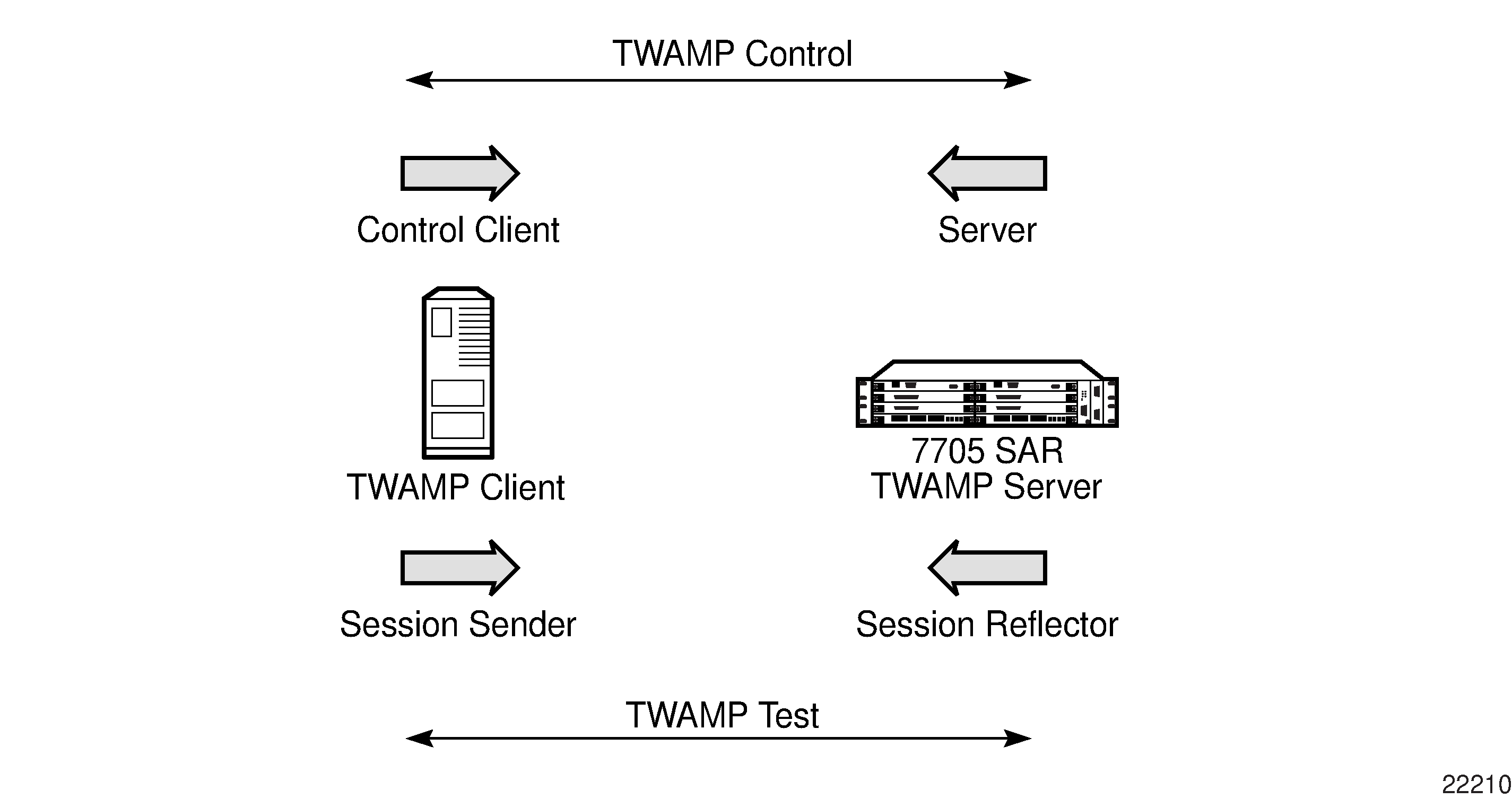
The 7705 SAR plays a passive role: the TWAMP control client initiates the control session with the 7705 SAR in order to negotiate the following:
the tests to be executed
the security protocol to be used
the port to be used
The 7705 SAR responds, and when the negotiation is complete, the 7705 SAR performs the following:
timestamps the TWAMP packets upon reception
processes the TWAMP packets and generates a response
timestamps the packets again before transmitting the response packets
TWAMP is supported on all IPv4 interfaces and on the base router of any interface address, including the system and loopback IP addresses. Any IP address can be used to terminate TWAMP control and test packets.
Datapath timestamping in both ingress and egress directions for TWAMP frames is supported on all datapath Ethernet ports on the following adapter cards, modules, and standalone nodes:
adapter cards
2-port 10GigE (Ethernet) Adapter card
6-port Ethernet 10Gbps Adapter card (high accuracy when using IEEE 1588v2 PTP time source)
8-port Gigabit Ethernet Adapter card (high accuracy when using IEEE 1588v2 PTP time source)
10-port 1GigE/1-port 10GigE X-Adapter card (high accuracy when using IEEE 1588v2 PTP time source)
Packet Microwave Adapter card (high accuracy when using IEEE 1588v2 PTP time source)
modules
2-port 10GigE (Ethernet) module
4-port SAR-H Fast Ethernet module
6-port SAR-M Ethernet module
standalone nodes
7705 SAR-A (high accuracy when using IEEE 1588v2 PTP time source)
7705 SAR-Ax (high accuracy when using IEEE 1588v2 PTP time source)
7705 SAR-H (high accuracy when using IEEE 1588v2 PTP time source)
7705 SAR-Hc (high accuracy when using IEEE 1588v2 PTP time source)
7705 SAR-M (high accuracy when using IEEE 1588v2 PTP time source)
7705 SAR-Wx (high accuracy when using IEEE 1588v2 PTP time source)
7705 SAR-X (high accuracy when using IEEE 1588v2 PTP time source)
CSM-based egress timestamping for TWAMP is supported on:
all TDM cards
2-port OC3/STM1 Channelized Adapter card
4-port DS3/E3 Adapter card
4-port OC3/STM1 Clear Channel Adapter card
16-port T1/E1 ASAP Adapter card
32-port T1/E1 ASAP Adapter card
Ethernet ports bound to a routed VPLS interface, where the frames are processed via the VPLS instance before reaching the IP interface
For information about how to configure the TWAMP server and the TWAMP command hierarchy, see the OAM commands for TWAMP.
The 7705 SAR supports a show>test-oam>twamp>server command that displays information about the TWAMP server configuration and statistics, and the clients associated with each server address prefix. See the Show Commands for more information. The 7705 SAR also supports a dump command that displays statistics for dropped connections, dropped connection states, rejected sessions, and dropped test packets. See Dump Test-OAM Commands for more information.
Interactions with Ethernet Loopback
Ethernet line loopbacks, being the lower layer functionality, take precedence over TWAMP operations. If an Ethernet port loopback is enabled, all frames including TWAMP frames are looped back. TWAMP frames cannot be processed on the interface until the loopback is released.
Limitations
The following limitations apply:
only the unauthenticated mode of TWAMP is supported. Authenticated and encrypted modes are excluded.
TWAMP does not support redundant HA configurations. During a CSM activity switch, all TWAMP control sessions are dropped and all tests that are in progress are terminated.
Two-Way Active Measurement Protocol Light (TWAMP Light)
TWAMP Light is an optional model included in the TWAMP standard RFC 5357, A Two-Way Active Measurement Protocol (TWAMP). TWAMP Light uses the standard TWAMP packet format but provides a simpler approach to gathering ongoing IP delay and synthetic loss performance data for the base router and per-VPRN statistics. Full details are described in Appendix I of RFC 5357.
With TWAMP Light, the TWAMP client/server model is replaced with a session controller/responder model. The server, control-client and session-sender role is combined in one host called the controller, and the session-reflector role is in another host called the responder. In general terms, the session controller is the launch point for the TWAMP test packets and the responder reflects the packets.
TWAMP Light maintains the TWAMP test packet exchange but eliminates the TWAMP TCP control connection with local configurations; however, not all negotiated control parameters are replaced with local configurations. The DSCP value in an incoming TWAMP test packet is reflected back to the originator. The incoming TWAMP test packet is classified to a specific FC based on the ingress QoS policy and the dot1p in the reflected packet is determined by the FC to dot1p mapping in the egress QoS policy.
The reflector function is configured under the config>router>twamp-light command hierarchy for base router reflection, and under the config>service>vprn> twamp-light command hierarchy for per-VPRN reflection. The TWAMP Light reflector function is configured per context and must be activated before reflection can occur; the function is not enabled by default for any context. The reflector requires the operator to define the TWAMP Light UDP listening port that identifies the TWAMP Light protocol and to define the prefixes that the reflector will accept as valid sources for a TWAMP Light request.
If the source IP address in the TWAMP Light packet arriving on the responder does not match a configured IP address prefix, the packet is dropped. Multiple prefix entries may be configured per context on the responder. Configured prefixes can be modified without shutting down the reflector function. An inactivity timeout under the config>oam-test>twamp>twamp-light command hierarchy defines the amount of time the reflector will keep the individual reflector sessions active in the absence of test packets.
TWAMP uses a single packet to gather both delay and loss metrics. This means there is special consideration over those approaches that use a specific tool per metric type.
TWAMP Light is supported for deployments that use IPv4 or IPv6 addressing, which may each have their own hardware requirements. All IP addressing must be unicast. IPv6 addresses cannot be reserved or link local addresses. Multiple test sessions may be configured between the same source and destination IP endpoints. The 4-tuple lookup (source IP, destination IP, source UDP, destination UDP provides a unique index for each test point.
7705 SAR Support for TWAMP Light Responder
TWAMP Light is supported on the same hardware as TWAMP. See 7705 SAR Support for TWAMP Server.
For information about how to configure the TWAMP Light reflector see the OAM commands for TWAMP Light.
Interactions with Ethernet Loopback
Ethernet line loopbacks, being the lower layer functionality, take precedence over TWAMP Light operations. If an Ethernet port loopback is enabled, all frames are looped back. Frames cannot be processed on the interface until the loopback is released.
Limitations
The 7705 SAR supports only the unauthenticated mode of TWAMP.
TWAMP Light Configuration Example
The following example shows a basic configuration using TWAMP Light to monitor two IP endpoints in a VPRN, including the default TWAMP Light values that were not overridden with configuration entries.
config>test-oam>twamp>twamp-light# info detail
--------------------------------------------------------------------------
(default)      inactivity-timeout 100
--------------------------------------------------------------------------
config>service>vprn# info
--------------------------------------------------------------------------
            route-distinguisher 65535:500
            auto-bind-tunnel
                resolution-filter
                    ldp
                exit
                resolution filter
            exit
            vrf-target target:65535:5000
            interface "to-cpe31" create
                address 10.1.1.1/30
                sap 1/1/2:500 create
                exit
            exit
            static-route-entry 192.168.1.0/24
                next-hop 10.1.1.2
                    no shutdown
                exit
            exit
            bgp
                no shutdown
            exit
            twamp-light
                reflector udp-port 64364 create
                    description "TWAMP Light reflector VPRN 500"
                    prefix 10.2.1.1/32 create
                        description "Process only 10.2.1.1 TWAMP Light Packets"
                    exit
                    prefix 172.16.1.0/24 create"
                        description "Process all 172.16.1.0 TWAMP Light packets"
                    exit
                    no shutdown
                exit
            exit
            no shutdown
----------------------------------------------
LSP Diagnostics
The 7705 SAR LSP diagnostics are implementations of LSP ping and LSP traceroute based on RFC 4379, Detecting Multi-Protocol Label Switched (MPLS) Data Plane Failures. LSP ping and LSP traceroute are modeled after the ICMP echo request/reply used by ping and traceroute to detect and localize faults in IP networks.
The downstream mapping TLV is used in LSP ping and LSP trace to allow the sender and responder nodes to exchange and validate interface and label stack information for each downstream hop of an LDP FEC, an RSVP LSP, a BGP labeled IPv4 route, an SR-ISIS node SID, or an SR-OSPF node SID. The 7705 SAR supports two downstream mapping TLVs: the original Downstream Mapping (DSMAP) TLV defined in RFC 4379 and the Downstream Detailed Mapping (DDMAP) TLV defined in RFC 6424.
This section describes the following topics:
LSP Ping
LSP ping, as described in RFC 4379, provides a mechanism to detect data plane failures in MPLS LSPs. For a specified FEC, LSP ping verifies whether the packet reaches the egress label edge router (eLER).
A 7705 SAR node using GNSS or IEEE 1588v2 PTP for time of day/phase recovery can perform LSP ping tests with high-accuracy timestamping. See the 7705 SAR Basic System Configuration Guide, "Node Timing", for information about node timing sources.
LSP Traceroute
LSP traceroute sends a packet to each transit LSR along a communications path until the far-end router is reached. The path is traced one LSR at a time, where each LSR that receives a traceroute packet replies to the initiating 7705 SAR with a packet that identifies itself. When the final LSR is identified, the initiating LSR has a list of all LSRs on the path. Like IP traceroute, LSP traceroute is a hop-by-hop operation (that is, LSR by LSR).
Use LSP traceroute to determine the exact litigation of LSP failures.
LSP Ping and LSP Traceroute for BGP Route Tunnels
LSP ping and LSP traceroute are supported on BGP route tunnels using existing LSP ping and traceroute commands with the bgp-label prefix option. The system uses the DSMAP TLV target FEC stack TLV for BGP-labeled IPv4 /32 prefix as defined in RFC 4379, Detecting Multi-Protocol Label Switched (MPLS) Data Plane Failures. Target FEC Stack TLV for BGP Labeled IPv4 Prefix shows the new TLV structure.
The following process is used when sending or responding to an LSP ping or LSP traceroute packet on BGP route tunnels.
The next hop of a BGP labeled route for a core IPv4 /32 prefix is always resolved to an LDP FEC or an RSVP-TE LSP. The transmitting node encapsulates the packet containing the echo request message with a label stack that consists of the LDP/RSVP-TE outer label and the BGP inner label.
If the packet expires on an RSVP-TE or LDP LSR node that does not have context for the BGP labeled IPv4 /32 prefix, the system must validate the outer label in the stack, and if the validation is successful, it must reply with return code 8 <Label switched at stack-depth <RSC>>.
An LSR node that is the next hop for the BGP labeled IPv4 /32 prefix, as well as the LER node that originated the BGP labeled IPv4 prefix, have full context for the BGP IPv4 target FEC stack and can therefore perform full validation of it.
For more information about BGP route tunnels, see the 7705 SAR Routing Protocols Guide, "BGP Route Tunnels".
TC Handling on BGP Route Tunnels
A 7705 SAR that process BGP 3107 labels always re-marks the TC bits. Ingress classification is based on the received TC/DSCP bits to FC. Egress re-marking is based on the QoS queue policy.
A 7705 SAR that does not process labels on a BGP route tunnel such as a 7705 SAR acting as an LSR, does not re-mark the TC bits.
BGP Route Tunnel Traceroute
Labeled BGP route tunnels pose a challenge to traceroute capability because there are two labels used in the transport layer: an inner BGP label identifying the far-end node and the regular label identifying the next hop for that far end.
Traceroute and TTL monitoring on the 7705 SAR have been enhanced to be able to identify and report every PE, ABR, ASBR, and P node along the path of a Layer 2 or Layer 3 service built partially or wholly over labeled BGP route tunnels.
Both the MPLS tunnel TTL and the labeled BGP route tunnel TTL are monitored for TTL expiry, which causes an ICMP TTL expired message to be sourced. Depending on the role of the intermediate nodes along the path, monitoring both TTL values is the most comprehensive way to ensure proper TTL handling.
Traceroute TTL for Self-generated Traffic
Depending on how the network is built on elements in the topology, a node along the path might be operating based on the outer MPLS tunnel label or the inner BGP label. In order to ensure that all the nodes along the path are displayed correctly, the 7705 SAR sets the TTL of the outer MPLS transport tunnel and the inner labeled BGP route tunnel to identical values. The next node is therefore identified and displayed correctly in a traceroute regardless of which label it is operating on.
For a self-generated traffic traceroute, both the MPLS and the labeled BGP TTLs are set to 1 in order to identify the first node. At the next hop, both TTL values are incremented to 2. This pattern continues at each hop in the path.
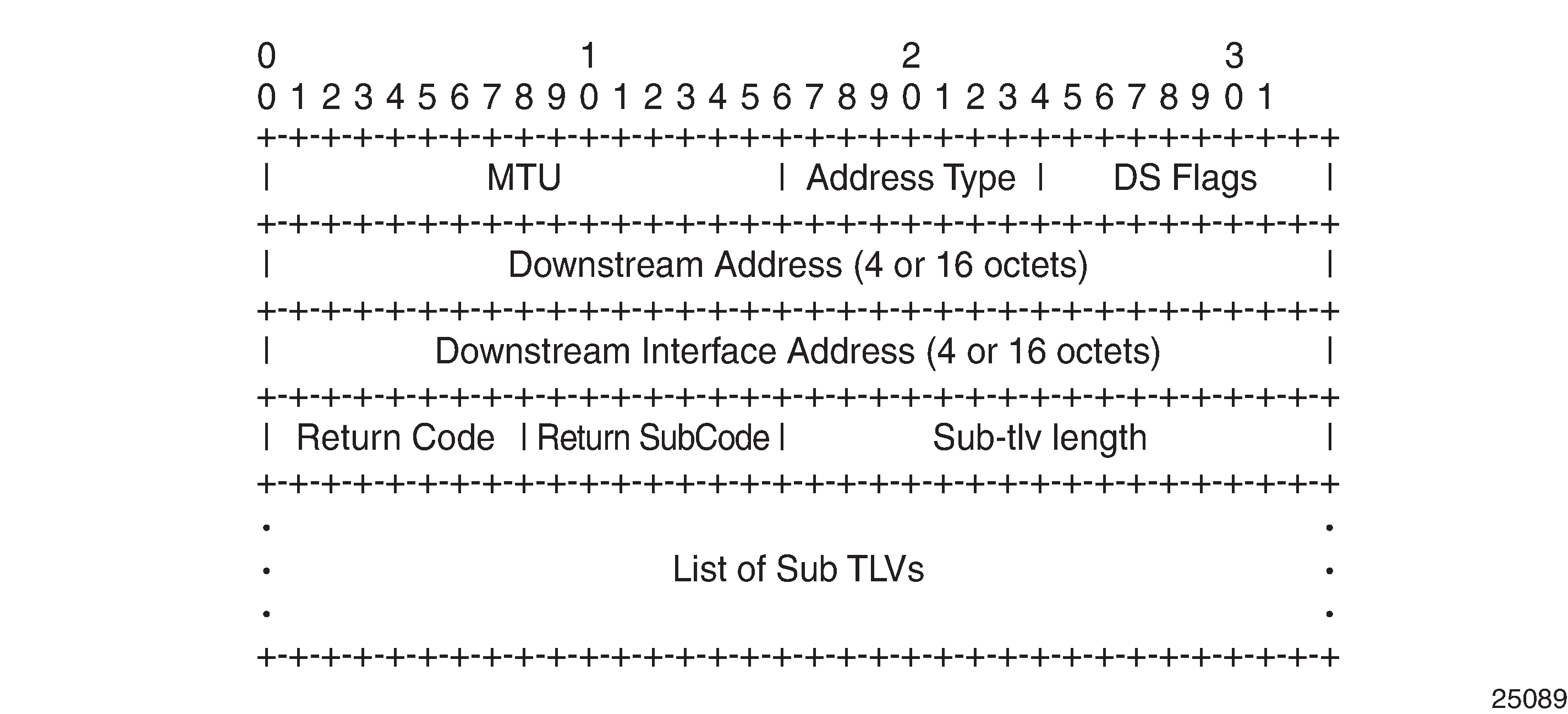
Downstream Detailed Mapping (DDMAP) TLV
The DDMAP TLV, as defined in RFC 6424, provides users with the same features as the existing DSMAP TLV along with enhancements that allow LSP diagnostics to trace the details of LSP hierarchy. With the DDMAP TLV, all intermediate routers will appear in the LSP ping and traceroute lists, and intermediate nodes can append additional data with details about their relative functionality. The DDMAP TLV format is derived from the DSMAP TLV format with variable length and optional fields converted into sub-TLVs. DDMAP TLV shows the DDMAP TLV format.
The following process is used when sending or responding to an LSP ping or LSP traceroute packet using the DSMAP or DDMAP TLV.
When either the DSMAP TLV or the DDMAP TLV is received in an echo request message, the responder node includes the same type of TLV in the echo reply message with the correct downstream interface information and label stack information.
If an echo request message without a DSMAP or DDMAP TLV expires at a node that is not the egress for the target FEC stack, the responder node always includes the DSMAP TLV in the echo reply message. This can occur in the following cases:
The user issues an LSP trace from a sender node with a min-ttl value higher than 1 and a max-ttl value lower than the number of hops required to reach the egress of the target FEC stack. This is the sender node behavior when the global configuration or the per-test setting of the DSMAP/DDMAP is set to DSMAP.
The user issues an LSP ping from a sender node with a TTL value lower than the number of hops required to reach the egress of the target FEC stack. This is the sender node behavior when the global configuration of the DSMAP/DDMAP is set to DSMAP.
If the global configuration or the per-test setting of the DSMAP TLV is set to DDMAP, the sender node includes the DDMAP TLV with the downstream IP address field set to the all-routers multicast address as per Section 3.3 of RFC 4379. The responder node then bypasses the interface and label stack validation and replies with a DDMAP TLV with the correct downstream information for the target FEC stack.
A sender node never includes the DSMAP or DDMAP TLV in an LSP ping message.
The user can globally configure the downstream mapping TLV to be used for all LSP trace and LDP treetrace packets with the configure test-oam mpls-echo-request-downstream-map command. The configured global value becomes the default downstream mapping TLV for all newly created LSP trace and LDP treetrace tests. It has no effect on existing tests and can be overridden on a specific test by setting the downstream-map-tlv parameter in the lsp-trace or ldp-treetrace context.
Using The DDMAP TLV in LSP Stitching and LSP Hierarchy
The DDMAP TLV provides full validation for a BGP IPv4 label route tunneled over an RSVP LSP or an LDP FEC.
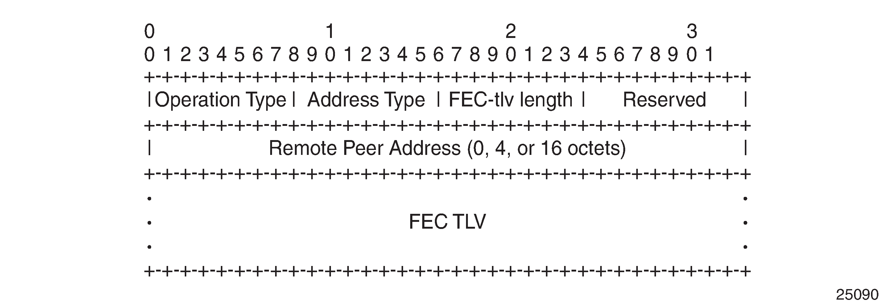
In order to properly check a target FEC that is stitched to another FEC (stitching FEC) of the same or a different type, or that is tunneled over another FEC (tunneling FEC), it is necessary for the responding nodes to provide details about the FEC manipulation to the sender node. The system collects this detailed information with the DDMAP TLV FEC stack change sub-TLV, shown in FEC Stack Change Sub-TLV. The field definitions match those of the DSMAP TLV and are described in RFC 4379.
The operation type specifies the action associated with the FEC stack change. FEC Stack Change Sub-TLV Operation Types defines the operation types for the FEC stack change sub-TLV.
Type # |
Operation |
|---|---|
1 |
Push |
2 |
Pop |
When DDMAP TLV is configured on an LSP trace that does not undergo stitching or tunneling operation in the network, the procedures at the sender and responder nodes are the same as in the case of the existing DSMAP TLV.
When DDMAP TLV is configured on an LSP trace that does undergo stitching or tunneling operation in the network, there are changes to the target FEC stack validation procedures at the sender and responder nodes. The following procedure represent a superset of the rules described in Section 4 of RFC 6424 to allow greater scope of interoperability with other vendor implementations.
Responder Node Procedures:
As a responder node, the 7705 SAR always inserts the global return code, 3 Replying router is an egress for the FEC at stack-depth <RSC> or the code, 14 See DDMAP TLV for Return Code and Return Subcode.
When the responder node inserts a global return code of 3, it does not include a DDMAP TLV.
When the responder node includes the DDMAP TLV, it inserts the global return code, 14 See DDMAP TLV for Return Code and Return Subcode. Additionally, the responder node will:
on a success response, include a return code of 15 in the DDMAP TLV for each downstream hop that has a FEC stack change sub-TLV
on a success response, include a return code, 8 Label switched at stackdepth <RSC> in the DDMAP TLV for each downstream hop if no FEC stack change sub-TLV is present
on a failure response, include an appropriate error return code in the DDMAP TLV for each downstream hop
A tunneling node indicates that it is pushing a FEC (the tunneling FEC) on top of the target FEC stack TLV by including a FEC stack change sub-TLV in the DDMAP TLV with a FEC operation type value of PUSH. It also includes a return code, 15 Label switched with FEC change. The downstream interface address and downstream IP address fields of the DDMAP TLV are populated for the pushed FEC. The remote peer address field in the FEC stack change sub-TLV is populated with the address of the control plane peer for the pushed FEC. The Label stack sub-TLV provides the full label stack over the downstream interface.
A node that is stitching a FEC indicates that it is performing a POP operation for the stitched FEC followed by a PUSH operation for the stitching FEC and potentially one PUSH operation for the transport tunnel FEC. The echo reply message will include two or more FEC stack change sub-TLVs in the DDMAP TLV. It also includes a return code 15 Label switched with FEC change. The downstream interface address and downstream address fields of the DDMAP TLV are populated for the stitching FEC. The remote peer address field in the FEC stack change sub-TLV of type POP is populated with a null value (0.0.0.0). The remote peer address field in the FEC stack change sub-TLV of type PUSH is populated with the address of the control plane peer for the tunneling FEC. The Label stack sub-TLV provides the full label stack over the downstream interface.
If the responder node is the egress for one or more FECs in the target FEC Stack, then it must reply with no DDMAP TLV and with a return code 3 Replying router is an egress for the FEC at stack-depth <RSC>. RSC must be set to the depth of the topmost FEC. This operation is iterative.
The receipt of the echo reply message the sender node will pop the topmost FEC from the target stack FEC TLV and resend the echo request message with the same TTL value as explained in step 5. The responder node performs the same operation until all FECs are popped or until the topmost FEC in the target FEC stack TLV matches the tunneled or stitched FEC. In the latter case, processing of the target FEC stack TLV follows again steps 1 or 2.
Sender Node Procedures:
If the echo reply message contains the return code 14 See DDMAP TLV for Return Code and Return Subcode and the DDMAP TLV has a return code 15 Label switched with FEC change, the sender node adjusts the target FEC Stack TLV in the echo request message for the next value of the TTL to reflect the operation on the current target FEC stack as indicated in the FEC stack change sub-TLV received in the DDMAP TLV of the last echo reply message. This results in one FEC being popped at most and one or more FECs being pushed as indicated.
If the echo reply message contains the return code 3 Replying router is an egress for the FEC at stack-depth <RSC>, then:
If the value for the label stack depth specified in the Return Sub-Code (RSC) field is the same as the depth of current target FEC Stack TLV, then the sender node considers the trace operation complete and terminates it. A 7705 SAR responder node will cause this case to occur as per Step 6 of the Responder Node Procedures.
If the value for the label stack depth specified in the Return Sub-Code (RSC) field is different from the depth of the current target FEC Stack TLV, the sender node must continue the LSP trace with the same TTL value after adjusting the target FEC stack TLV by removing the top FEC.
This step continues iteratively until the value for the label stack depth specified in the Return Sub Code (RSC) field is the same as the depth of current target FEC Stack TLV, at which point step a is performed. A 7705 SAR responder node causes this case to occur as per Step 6 of the responder node procedures.
If a DDMAP TLV with or without a FEC stack change sub-TLV is included, then the sender node ignores it and processing is performed as per steps (a) or (b) above. A 7705 SAR responder node does not cause this case to occur but a third party implementation may.
As a sender node, the 7705 SAR can accept an echo-reply message with the global return code of either 14 (with DDMAP TLV return code of 15 or 8), or 15 and process the FEC stack change TLV as per Step 1 of the Sender Node Procedures.
If an LSP ping is performed directly to the egress LER of the stitched FEC, there is no DDMAP TLV included in the echo request message and the responder node, which is the egress node, still replies with return code 4 Replying router has no mapping for the FEC at stack- depth <RSC>. This case cannot be resolved with this feature.
BGP 3107 Tunnel Through LDP FEC and the following LSP trace examples illustrate how the 7705 SAR provides validation for a BGP IPv4 label route tunneled over an RSVP LSP or an LDP FEC.
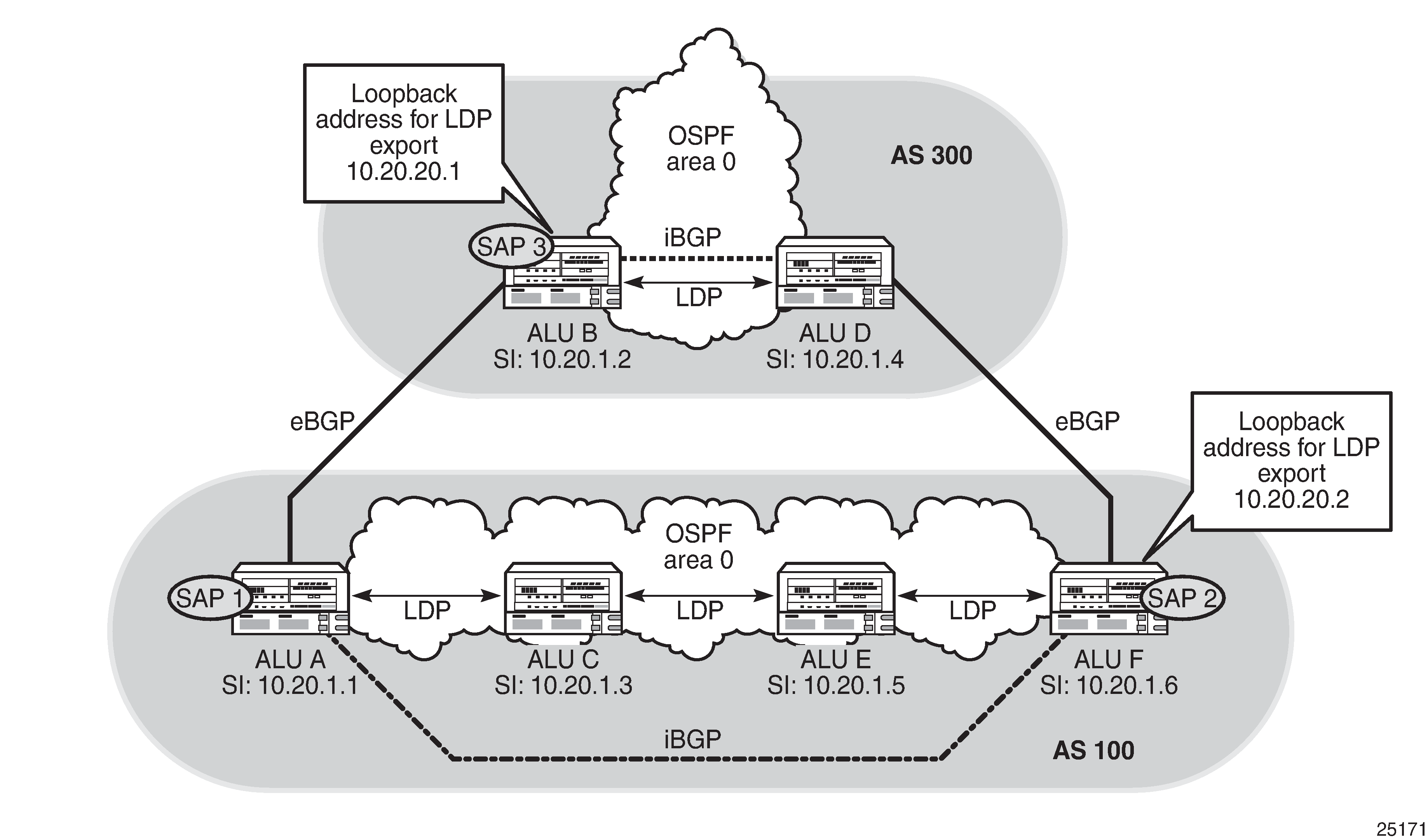
LSP trace launched from ALU-A (AS 100) to ALU-D (AS 300) with the DSMAP option:
ALU-A# oam lsp-trace bgp-label prefix 10.20.1.4/32 downstream-map-tlv dsmap src-ip-
address 10.20.1.1
lsp-trace to 10.20.1.4/32: 0 hops min, 0 hops max, 104 byte packets
1  10.20.1.3  rtt=3.63ms rc=8(DSRtrMatchLabel)
2  10.20.1.5  rtt=9.04ms rc=8(DSRtrMatchLabel)
3  10.20.1.6  rtt=7.73ms rc=8(DSRtrMatchLabel) rsc=1
4  10.20.1.4  rtt=1.62ms rc=3(EgressRtr) rsc=1
LSP trace launched from ALU-A (AS 100) to ALU-D (AS 300) with the DDMAP option:
ALU-A# oam lsp-trace bgp-label prefix 10.20.1.4/32 downstream-map-tlv ddmap src-ip-
address 10.20.1.1
lsp-trace to 10.20.1.4/32: 0 hops min, 0 hops max, 124 byte packets
1  10.20.1.3  rtt=9.29ms rc=8(DSRtrMatchLabel) rsc=2
2  10.20.1.5  rtt=3.69ms rc=8(DSRtrMatchLabel) rsc=2
3  10.20.1.6  rtt=2.81ms rc=3(EgressRtr) rsc=2
3  10.20.1.6  rtt=11.5ms rc=8(DSRtrMatchLabel) rsc=1
4  10.20.1.4  rtt=1.68ms rc=3(EgressRtr) rsc=1
LSP trace launched from ALU-B (AS 300) to ALU-F (AS 100) with the DSMAP option:
ALU-B# oam lsp-trace bgp-label prefix 10.20.1.6/32 downstream-map-tlv dsmap src-ip-
address 10.20.1.2
lsp-trace to 10.20.1.6/32: 0 hops min, 0 hops max, 104 byte packets
1  10.20.1.1  rtt=5.39ms rc=8(DSRtrMatchLabel) rsc=1
2  10.1.3.2  *
3  10.1.3.2  *
4  10.20.1.6  rtt=1.27ms rc=10(DSRtrUnmatchLabel) rsc=1
LSP trace launched from ALU-B (AS 300) to ALU-F (AS 100) with the DDMAP option:
ALU-B# oam lsp-trace bgp-label prefix 10.20.1.6/32 downstream-map-tlv ddmap src-ip-
address 10.20.1.2
lsp-trace to 10.20.1.6/32: 0 hops min, 0 hops max, 108 byte packets
1  10.20.1.1  rtt=10.8ms rc=15(LabelSwitchedWithFecChange) rsc=1
2  10.1.3.2  *
3  10.0.0.2  *
4  10.20.1.6  rtt=1.29ms rc=3(EgressRtr) rsc=2
4  10.20.1.6  rtt=1.23ms rc=5(DSMappingMismatched) rsc=1
MPLS OAM Support in Segment Routing
MPLS OAM supports segment routing extensions to LSP ping and LSP traceroute as specified in draft-ietf-mpls-spring-lsp-ping.
Segment routing (SR) performs both shortest path and source-based routing. When the data plane uses MPLS encapsulation, the MPLS OAM and SAA lsp-ping and lsp-trace commands can be used to check connectivity and trace the path to any midpoint or endpoint of an SR-ISIS tunnel, SR-OSPF tunnel, or SR-TE LSP.
Configurable options for thelsp-ping and lsp-trace commands in the oam and config>saa>test>type contexts are available for the following types of segment routing tunnels:
SR-ISIS and SR-OSPF node segment ID (SID) tunnels
SR-TE LSPs
SR Extensions for LSP Ping and LSP Traceroute
This section describes how MPLS OAM models the SR tunnel types.
An SR shortest path tunnel, SR-ISIS tunnel, or SR-OSPF tunnel uses a single FEC element in the target FEC stack TLV. The FEC corresponds to the prefix of the SID in a specific IGP instance.
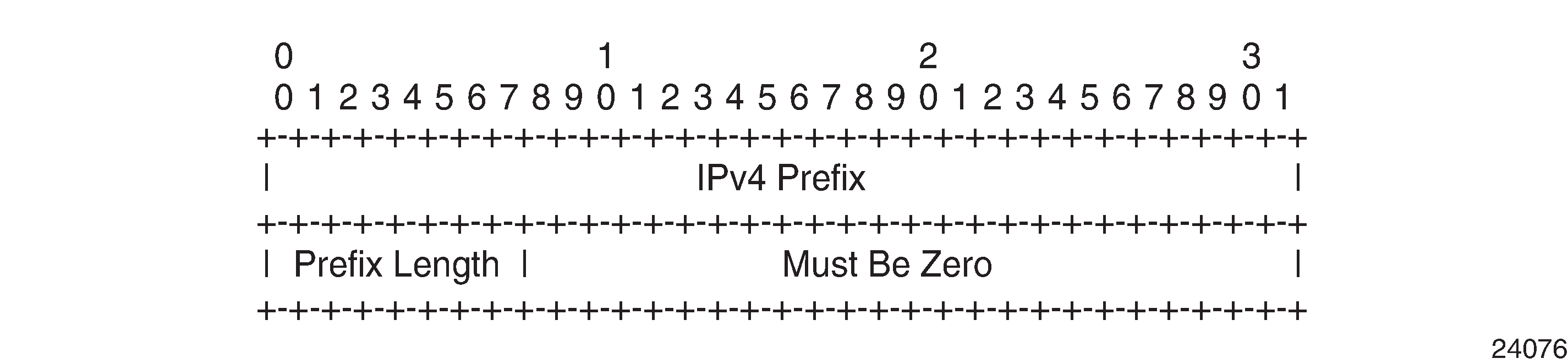
IPv4 IGP prefix SID shows the format for the IPv4 IGP prefix SID.
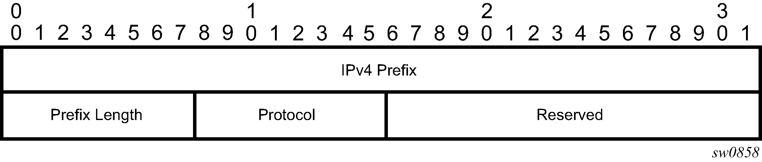
The fields are defined as follows:
IPv4 Prefix
This field carries the IPv4 prefix to which the SID is assigned. If the prefix is shorter than 32 bits, trailing bits must be set to 0.
Prefix Length
This field is one octet and gives the length of the prefix in bits (values can be from 1 to 32).
Protocol
This field is set to 1 when the IGP is OSPF and set to 2 when the IGP is IS-IS.
IPv6 IGP prefix SID shows the format for the IPv6 IGP prefix SID.
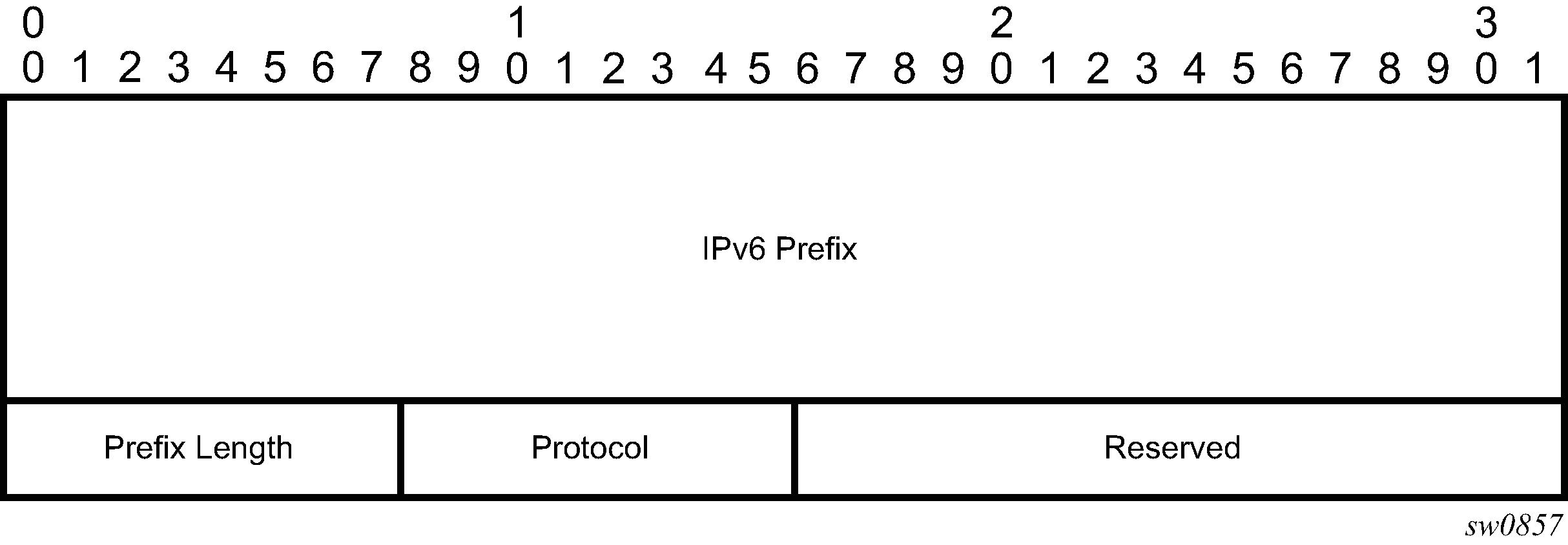
The fields are defined as follows:
IPv6 Prefix
This field carries the IPv6 prefix to which the SID is assigned. If the prefix is shorter than 128 bits, trailing bits must be set to 0.
Prefix Length
This field is one octet and gives the length of the prefix in bits (values can be from 1 to 128).
Protocol
This field is set to 1 when the IGP protocol is OSPF and set to 2 when the IGP protocol is IS-IS.
As a hierarchical LSP, an SR-TE LSP uses the target FEC stack TLV, which contains a FEC element for each node SID and each adjacency SID in the path of the SR-TE LSP. Because the SR-TE LSP does not instantiate a state in the LSR other than the ingress LSR, MPLS OAM tests a hierarchy of node SID and adjacency SID segments toward the destination of the SR-TE LSP. IPv6 IGP prefix SID shows the format for the node SID. IGP Adjacency SID shows the format for the IGP Adjacency SID.
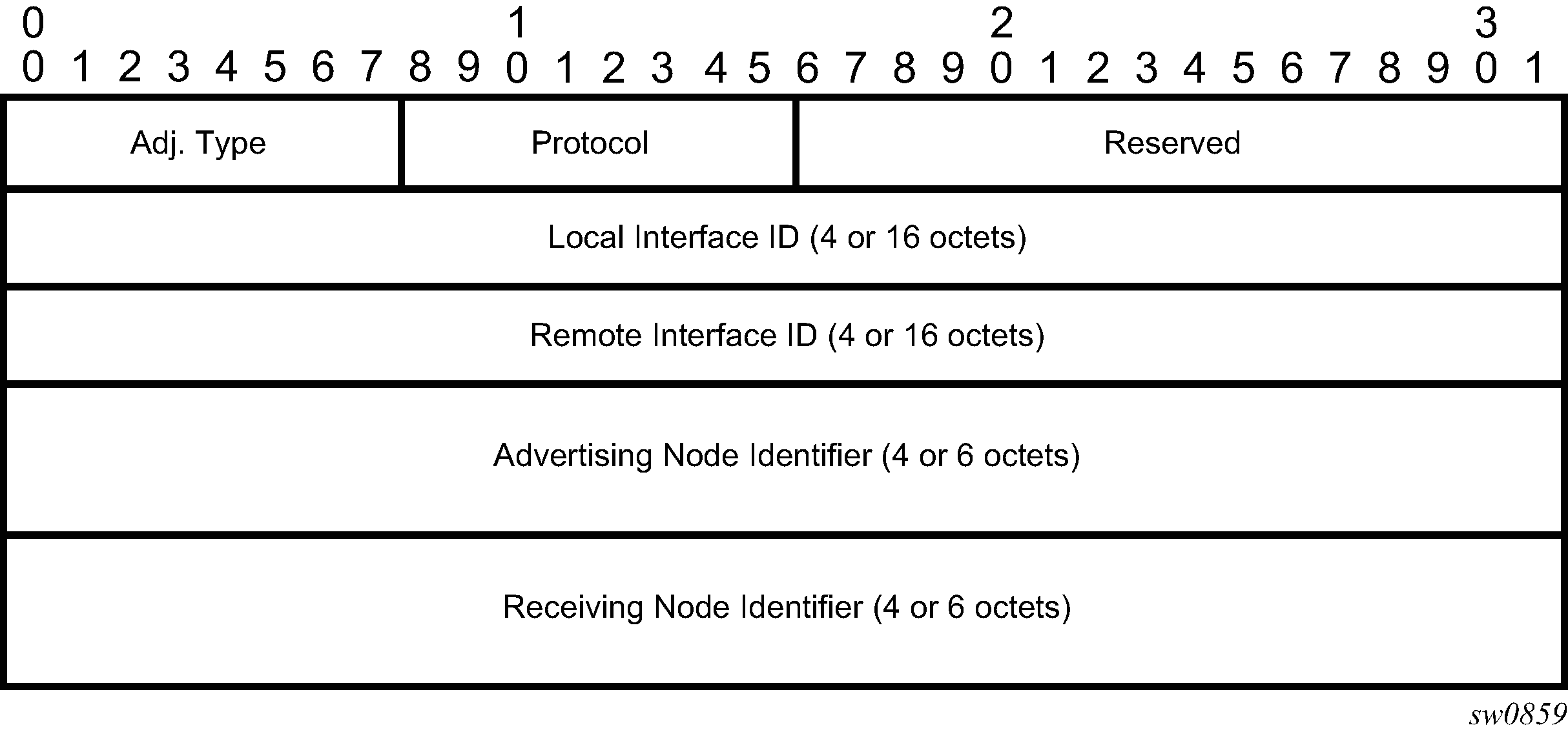
The fields are defined as follows:
Adj. Type (Adjacency Type)
This field is set to 1 when the adjacency segment is a parallel adjacency as defined in draft.ietf-spring-segment-routing. This field is set to 4 when the adjacency segment is IPv4-based and is not a parallel adjacency. This field is set to 6 when the adjacency segment is IPv6-based and is not a parallel adjacency.
Protocol
This field is set to 1 when the IGP protocol is OSPF and set to 2 when the IGP protocol is IS-IS.
Local Interface ID
This field is an identifier that is assigned by the local LSR for a link on which the adjacency SID is bound. This field is set to a local link address (IPv4 or IPv6). If unnumbered, the 32-bit link identifier defined in RFC 4203 and RFC 5307 is used. If the adjacency SID represents parallel adjacencies, as described in draft.ietf-spring-segment-routing, this field must be set to 0.
Remote Interface ID
This field is an identifier that is assigned by the remote LSR for a link on which the adjacency SID is bound. This field is set to the remote (downstream neighbor) link address (IPv4 or IPv6). If unnumbered, the 32-bit link identifier defined in RFC 4203 and RFC 5307 is used. If the adjacency SID represents parallel adjacencies, as described in draft.ietf-spring-segment-routing, this field must be set to 0.
Advertising Node Identifier
This field specifies the advertising node identifier. When the Protocol field is set to 1, the 32 rightmost bits represent the OSPF router ID. When the Protocol field is set to 2, this field carries the 48-bit IS-IS system ID.
Receiving Node Identifier
This field specifies the downstream node identifier. When the Protocol field is set to 1, the 32 rightmost bits represent the OSPF router ID. When the Protocol field is set to 2, this field carries the 48-bit IS-IS system ID.
Both lsp-ping and lsp-trace apply to the following contexts:
SR-ISIS or SR-OSPF shortest path IPv4 tunnel
SR-ISIS shortest path IPv6 tunnel
IS-IS SR-TE IPv4 LSP or OSPF SR-TE IPv4 LSP
BGP IPv4 LSP resolved over an SR-ISIS IPv4 tunnel, an SR-OSPF IPv4 tunnel, or an SR-TE IPv4 LSP, including support for BGP LSP across AS boundaries and for ECMP next hops at the transport tunnel level
LSP Ping and LSP Traceroute on SR-ISIS or SR-OSPF Tunnels
The following operations apply to lsp-ping and lsp-trace commands on SR-ISIS tunnels or SR-OSPF tunnels:
The sender node builds the target FEC stack TLV with a single FEC element corresponding to the node SID of the destination of the SR-ISIS or SR-OSPF tunnel.
A node SID label that is swapped at an LSR results in a return code of 8, ‟Label switched at stack-depth <RSC>”, per RFC 8029.
A node SID label that is popped at an LSR results in a return code of 3, ‟Replying router is an egress for the FEC at stack-depth <RSC>”.
The lsp-trace command supports the following downstream mapping TLV parameters: ddmap, dsmap, or none. When the downstream mapping TLV is configured as none, no map TLV is sent. The downstream interface information is returned along with the egress label for the node SID tunnel and the protocol that resolved the node SID at the responder node.
Testing MPLS OAM with SR tunnels shows an example of the topology used for LSP ping and LSP trace for an SR-ISIS node SID tunnel.
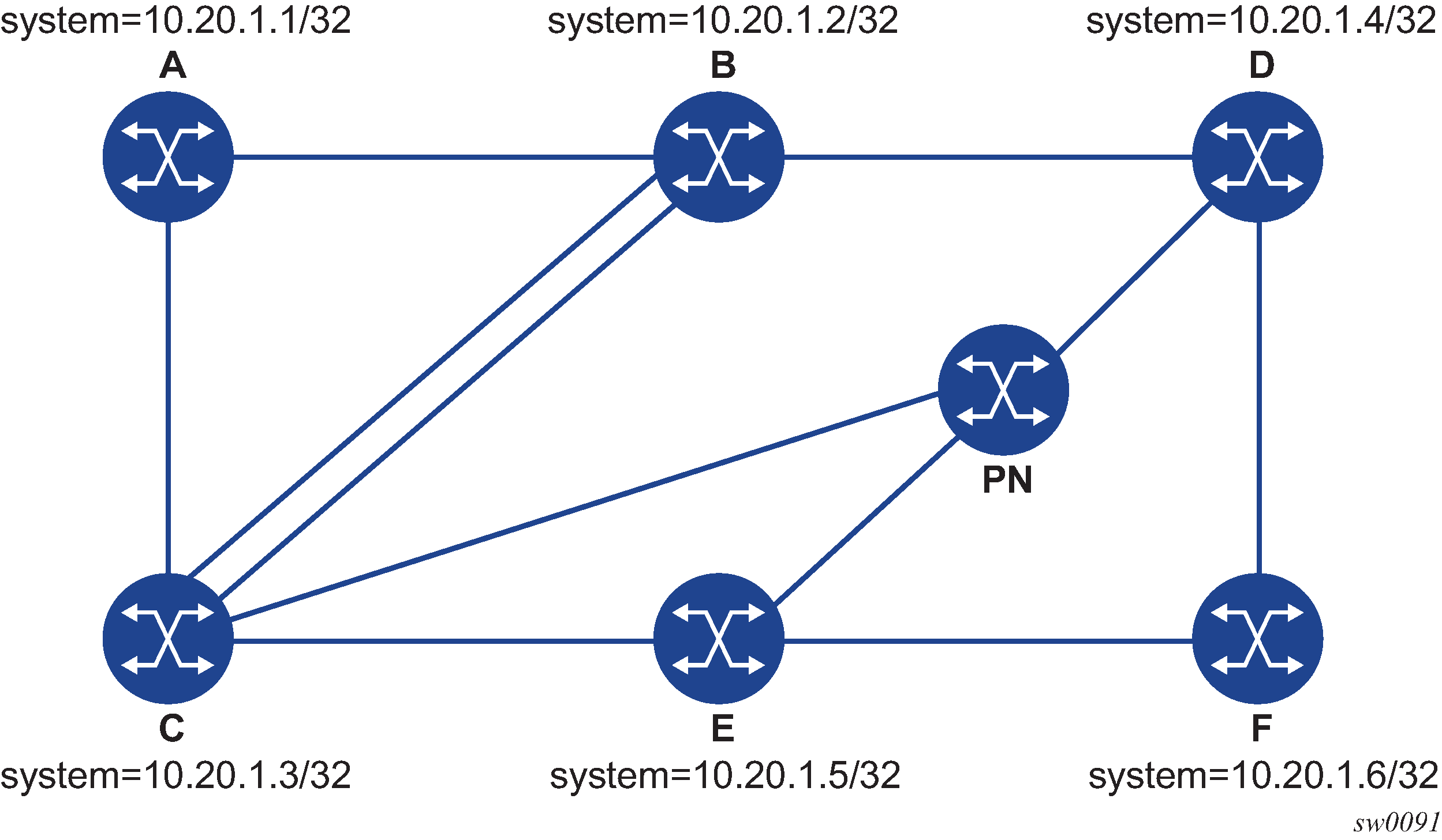
Based on this topology, the following is an output example for LSP ping on DUT-A for target node SID of DUT-F:
*A:Dut-A# oam lsp-ping sr-isis prefix 10.20.1.6/32 igp-instance 0 detail
LSP-PING 10.20.1.6/32: 80 bytes MPLS payload
Seq=1, send from intf int_to_B, reply from 10.20.1.6
       udp-data-len=32 ttl=255 rtt=1220324ms rc=3 (EgressRtr)
---- LSP 10.20.1.6/32 PING Statistics ----
1 packets sent, 1 packets received, 0.00% packet loss
round-trip min = 1220324ms, avg = 1220324ms, max = 1220324ms, stddev = 0.000ms
The following is an output example for LSP trace on DUT-A for target node SID of DUT-F (DSMAP TLV):
*A:Dut-A# oam lsp-trace sr-isis prefix 10.20.1.6/32 igp-instance 0 downstream-map-tlv dsmap detail
lsp-trace to 10.20.1.6/32: 0 hops min, 0 hops max, 108 byte packets
1  10.20.1.2  rtt=1220323ms rc=8(DSRtrMatchLabel) rsc=1
     DS 1: ipaddr=10.10.4.4 ifaddr=10.10.4.4 iftype=ipv4Numbered MRU=1496
           label[1]=26406 protocol=6(ISIS)
2  10.20.1.4  rtt=1220323ms rc=8(DSRtrMatchLabel) rsc=1
     DS 1: ipaddr=10.10.9.6 ifaddr=10.10.9.6 iftype=ipv4Numbered MRU=1496
           label[1]=26606 protocol=6(ISIS)
3  10.20.1.6  rtt=1220324ms rc=3(EgressRtr) rsc=1
The following is an output example for LSP trace on DUT-A for target node SID of DUT-F (DDMAP TLV):
*A:Dut-A# oam lsp-trace sr-isis prefix 10.20.1.6/32 igp-instance 0 downstream-map-tlv ddmap detail
lsp-trace to 10.20.1.6/32: 0 hops min, 0 hops max, 108 byte packets
1  10.20.1.2  rtt=1220323ms rc=8(DSRtrMatchLabel) rsc=1
     DS 1: ipaddr=10.10.4.4 ifaddr=10.10.4.4 iftype=ipv4Numbered MRU=1496
           label[1]=26406 protocol=6(ISIS)
2  10.20.1.4  rtt=1220324ms rc=8(DSRtrMatchLabel) rsc=1
     DS 1: ipaddr=10.10.9.6 ifaddr=10.10.9.6 iftype=ipv4Numbered MRU=1496
           label[1]=26606 protocol=6(ISIS)
3  10.20.1.6  rtt=1220324ms rc=3(EgressRtr) rsc=1
LSP Ping and LSP Traceroute on SR-TE LSPs
The following operations apply to lsp-ping and lsp-trace commands on SR-TE LSPs:
The sender node builds a target FEC stack TLV that contains FEC elements.
For lsp-ping, the target FEC stack TLV contains a single FEC element that corresponds to the last segment, that is, a node SID or an adjacency SID of the destination of the SR-TE LSP.
For lsp-trace, the target FEC stack TLV contains a FEC element for each node SID and for each adjacency SID in the path of the SR-TE LSP, including the SID of the destination of the SR-TE LSP.
A node SID label that is popped at an LSR results in a return code of 3, ‟Replying router is an egress for the FEC at stack-depth <RSC>”.
An adjacency SID label that is popped at an LSR results in a return code of 3, ‟Replying router is an egress for the FEC at stack-depth <RSC>”.
A node SID label that is swapped at an LSR results in a return code of 8, ‟Label switched at stack-depth <RSC>”, per RFC 8029.
An adjacency SID label that is swapped at an LSR results in a return code of 8, ‟Label switched at stack-depth <RSC>”, per RFC 8029.
The lsp-trace command includes the option to specify the downstream mapping TLV format to use in the LSP trace packet: ddmap, dsmap, or none. When none is configured, no map TLV is sent. The downstream interface information is returned along with the egress label for the node SID tunnel or the adjacency SID tunnel of the current segment as well as the protocol that resolved the tunnel at the responder node.
If the target FEC stack TLV contains more than one FEC element, the responder node that is the termination of one node SID or adjacency SID segment pops its own SID in the first operation. When the sender node receives this reply, it adjusts the target FEC stack TLV by stripping the top FEC before sending the probe for the next TTL value. When the responder node receives the next echo request message with the same TTL value from the sender node for the next node SID or adjacency SID segment in the stack, it performs a swap operation to that next segment.
When the path of the SR-TE LSP is computed by the sender node, the hop-to-label translation tool returns the IGP instance that was used to determine the labels for each hop in the path. When the path of the SR-TE LSP is computed by a PCE, the protocol ID is not returned by the PCEP. In this case, the sender node performs a lookup in the SR module for the IGP instance that resolved the first segment of the path. In both cases, the IGP is used to encode the protocol ID field of the node SID or adjacency SID in each of the FEC elements of the target FEC stack TLV.
The responder node validates the top FEC in the target FEC stack TLV, provided that the depth of the incoming label stack in the packet header is greater than the depth of the target FEC stack TLV.
TTL values can be changed.
The ttl parameter in the lsp-ping command can be set to a value lower than 255 and the responder node replies if the FEC element in the target FEC stack TLV corresponds to a node SID resolved at that node. The responder node, however, fails the validation if the FEC element in the target FEC stack TLV is the adjacency of a remote node. The return code in the echo reply message is either ‟rc=4(NoFECMapping)” or ‟rc=10(DSRtrUnmatchLabel)”.
The min-ttl and max-ttl parameters in the lsp-trace command can be set to values other than the default. However, lsp-trace can only properly trace the partial path of an SR-TE LSP if there is no segment termination before the node that corresponds to the minimum TTL value. Otherwise, it fails validation and returns an error because the responder node receives a target FEC stack depth that is greater than the incoming label stack size. The return code in the echo reply message is ‟rc=4(NoFECMapping)”, ‟rc=5(DSMappingMismatched)”, or ‟rc=10(DSRtrUnmatchLabel)”.
This scenario is true whether the downstream-map-tlv option is set to ddmap, dsmap, or none.
The following are output examples for LSP ping and LSP trace on SR-TE LSPs. The first example uses a path with strict hops, each corresponding to an adjacency SID, while the second example uses a path with loose hops, each corresponding to a node SID. The topology for the examples is shown in Testing MPLS OAM with SR-TE LSPs.
Example 1
The following output is an example of LSP ping and LSP trace on DUT-A for a strict-hop adjacency SID SR-TE LSP, where:
the source is DUT-A
the destination is DUT-F
the path is as follows: A to B, B to C, C to E, E to D, D to F
*A:Dut-A# oam lsp-ping sr-te "srteABCEDF" detail
LSP-PING srteABCEDF: 96 bytes MPLS payload
Seq=1, send from intf int_to_B, reply from 10.20.1.6
       udp-data-len=32 ttl=255 rtt=1220325ms rc=3 (EgressRtr)
---- LSP srteABCEDF PING Statistics ----
1 packets sent, 1 packets received, 0.00% packet loss
round-trip min = 1220325ms, avg = 1220325ms, max = 1220325ms, stddev = 0.000ms
*A:Dut-A# oam lsp-trace sr-te "srteABCEDF" downstream-map-tlv ddmap detail
lsp-trace to srteABCEDF: 0 hops min, 0 hops max, 252 byte packets
1  10.20.1.2  rtt=1220323ms rc=3(EgressRtr) rsc=5
1  10.20.1.2  rtt=1220322ms rc=8(DSRtrMatchLabel) rsc=4
     DS 1: ipaddr=10.10.33.3 ifaddr=10.10.33.3 iftype=ipv4Numbered MRU=1520
           label[1]=3 protocol=6(ISIS)
           label[2]=262135 protocol=6(ISIS)
           label[3]=262134 protocol=6(ISIS)
           label[4]=262137 protocol=6(ISIS)
2  10.20.1.3  rtt=1220323ms rc=3(EgressRtr) rsc=4
2  10.20.1.3  rtt=1220323ms rc=8(DSRtrMatchLabel) rsc=3
     DS 1: ipaddr=10.10.5.5 ifaddr=10.10.5.5 iftype=ipv4Numbered MRU=1496
           label[1]=3 protocol=6(ISIS)
           label[2]=262134 protocol=6(ISIS)
           label[3]=262137 protocol=6(ISIS)
3  10.20.1.5  rtt=1220325ms rc=3(EgressRtr) rsc=3
3  10.20.1.5  rtt=1220325ms rc=8(DSRtrMatchLabel) rsc=2
     DS 1: ipaddr=10.10.11.4 ifaddr=10.10.11.4 iftype=ipv4Numbered MRU=1496
           label[1]=3 protocol=6(ISIS)
           label[2]=262137 protocol=6(ISIS)
4  10.20.1.4  rtt=1220324ms rc=3(EgressRtr) rsc=2
4  10.20.1.4  rtt=1220325ms rc=8(DSRtrMatchLabel) rsc=1
     DS 1: ipaddr=10.10.9.6 ifaddr=10.10.9.6 iftype=ipv4Numbered MRU=1496
           label[1]=3 protocol=6(ISIS)
5  10.20.1.6  rtt=1220325ms rc=3(EgressRtr) rsc=1
Example 2
The following output is an example of LSP ping and LSP trace on DUT-A for a loose-hop node SID SR-TE LSP, where:
the source is DUT-A
the destination is DUT-F
the path is A, B, C, E
*A:Dut-A# oam lsp-ping sr-te "srteABCE_loose" detail
LSP-PING srteABCE_loose: 80 bytes MPLS payload
Seq=1, send from intf int_to_B, reply from 10.20.1.5
       udp-data-len=32 ttl=255 rtt=1220324ms rc=3 (EgressRtr)
---- LSP srteABCE_loose PING Statistics ----
1 packets sent, 1 packets received, 0.00% packet loss
round-trip min = 1220324ms, avg = 1220324ms, max = 1220324ms, stddev = 0.000ms
*A:Dut-A# oam lsp-trace sr-te "srteABCE_loose" downstream-map-tlv ddmap detail
lsp-trace to srteABCE_loose: 0 hops min, 0 hops max, 140 byte packets
1  10.20.1.2  rtt=1220323ms rc=3(EgressRtr) rsc=3
1  10.20.1.2  rtt=1220322ms rc=8(DSRtrMatchLabel) rsc=2
     DS 1: ipaddr=10.10.3.3 ifaddr=10.10.3.3 iftype=ipv4Numbered MRU=1496
           label[1]=26303 protocol=6(ISIS)
           label[2]=26305 protocol=6(ISIS)
     DS 2: ipaddr=10.10.12.3 ifaddr=10.10.12.3 iftype=ipv4Numbered MRU=1496
           label[1]=26303 protocol=6(ISIS)
           label[2]=26305 protocol=6(ISIS)
     DS 3: ipaddr=10.10.33.3 ifaddr=10.10.33.3 iftype=ipv4Numbered MRU=1496
           label[1]=26303 protocol=6(ISIS)
           label[2]=26305 protocol=6(ISIS)
2  10.20.1.3  rtt=1220323ms rc=3(EgressRtr) rsc=2
2  10.20.1.3  rtt=1220323ms rc=8(DSRtrMatchLabel) rsc=1
     DS 1: ipaddr=10.10.5.5 ifaddr=10.10.5.5 iftype=ipv4Numbered MRU=1496
           label[1]=26505 protocol=6(ISIS)
     DS 2: ipaddr=10.10.11.5 ifaddr=10.10.11.5 iftype=ipv4Numbered MRU=1496
           label[1]=26505 protocol=6(ISIS)
3  10.20.1.5  rtt=1220324ms rc=3(EgressRtr) rsc=1
LSP Ping and LSP Trace for BGP IPv4 LSPs
The 7705 SAR supports LSP ping and LSP trace on a BGP IPv4 LSP resolved over an SR-OSPF IPv4 tunnel, an SR-ISIS IPv4 tunnel, or an SR-TE IPv4 LSP.
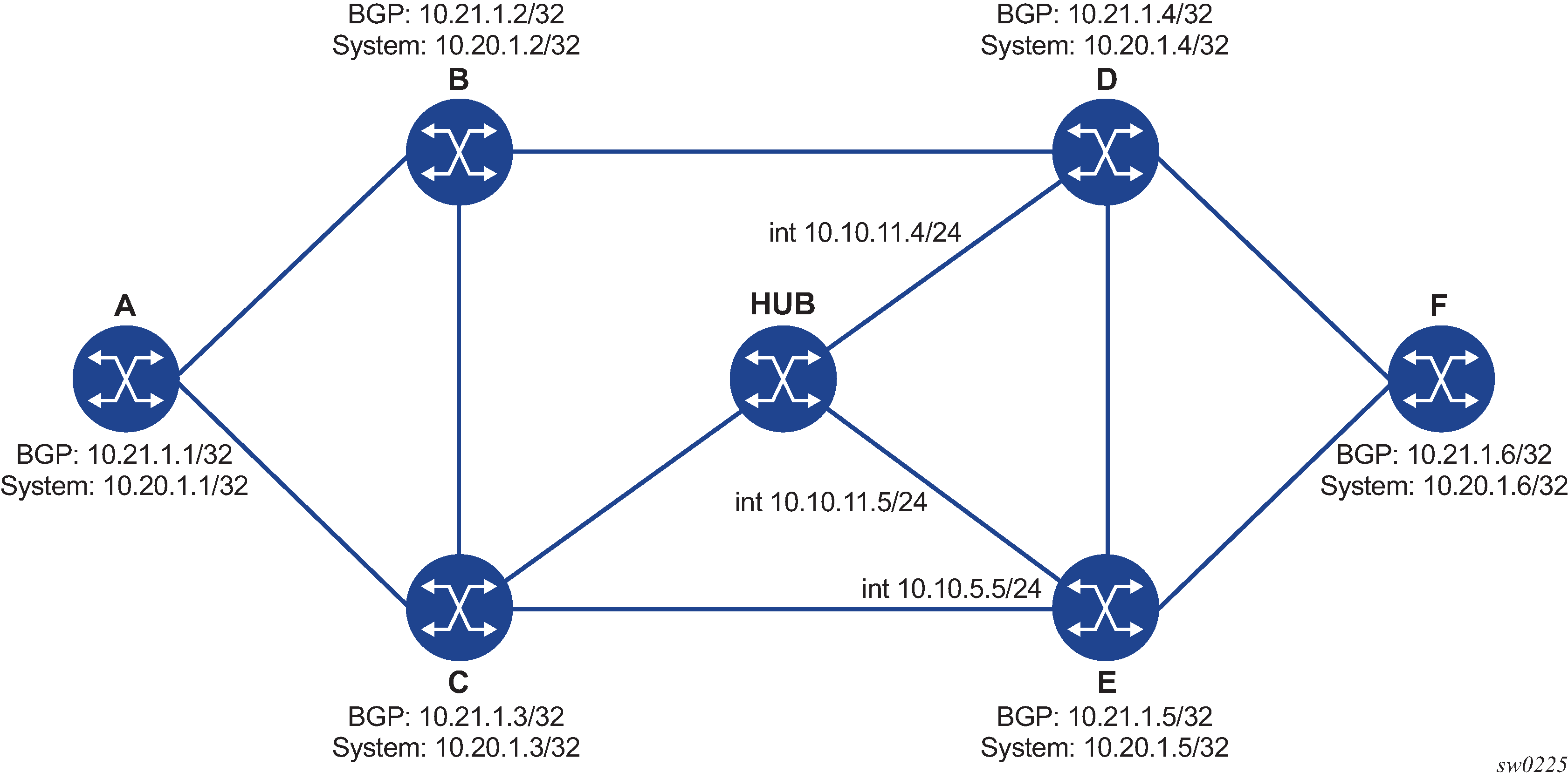
The following are output examples of LSP trace for a hierarchical tunnel consisting of a BGP IPv4 LSP resolved over an SR-OSPF IPv4 tunnel, an SR-ISIS IPv4 tunnel, or an SR-TE IPv4 LSP (OSPF or IS-IS). The topology for the examples is shown in Testing MPLS OAM for BGP over SR-OSPF, SR-TE (OSPF), SR-ISIS, and SR-TE (ISIS).
Output example for BGP over SR-OSPF:
*A:Dut-A# oam lsp-trace bgp-label prefix 11.21.1.6/32 detail downstream-map-tlv ddmap path-destination 127.1.1.
lsp-trace to 11.21.1.6/32: 0 hops min, 0 hops max, 168 byte packets
1  10.20.1.3  rtt=2.31ms rc=8(DSRtrMatchLabel) rsc=2
     DS 1: ipaddr=10.10.5.5 ifaddr=10.10.5.5 iftype=ipv4Numbered MRU=1496
           label[1]=27506 protocol=5(OSPF)
           label[2]=13199 protocol=2(BGP)
     DS 2: ipaddr=10.10.11.4 ifaddr=10.10.11.4 iftype=ipv4Numbered MRU=1496
           label[1]=27406 protocol=5(OSPF)
           label[2]=262137 protocol=2(BGP)
     DS 3: ipaddr=10.10.11.5 ifaddr=10.10.11.5 iftype=ipv4Numbered MRU=1496
           label[1]=27506 protocol=5(OSPF)
           label[2]=262137 protocol=2(BGP)
2   10.20.1.4  rtt=4.91ms rc=8(DSRtrMatchLabel) rsc=2
     DS 1: ipaddr=10.10.9.6 ifaddr=10.10.9.6 iftype=ipv4Numbered MRU=1492
           label[1]=27606 protocol=5(OSPF)
           label[2]=262137 protocol=2(BGP)
3  10.20.1.6  rtt=4.73ms rc=3(EgressRtr) rsc=2
3  10.20.1.6  rtt=5.44ms rc=3(EgressRtr) rsc=1
*A:Dut-A#
Output example for BGP over SR-TE (OSPF):
*A:Dut-A# oam lsp-trace bgp-label prefix 11.21.1.6/32 detail downstream-map-tlv ddmap path-destination 127.1.1.1
lsp-trace to 11.21.1.6/32: 0 hops min, 0 hops max, 236 byte packets
1  10.20.1.2  rtt=2.13ms rc=3(EgressRtr) rsc=4
1  10.20.1.2  rtt=1.79ms rc=8(DSRtrMatchLabel) rsc=3
     DS 1: ipaddr=10.10.4.4 ifaddr=10.10.4.4 iftype=ipv4Numbered MRU=1492
           label[1]=3 protocol=5(OSPF)
           label[2]=262104 protocol=5(OSPF)
           label[3]=262139 protocol=2(BGP)
2  10.20.1.4  rtt=3.24ms rc=3(EgressRtr) rsc=3
2  10.20.1.4  rtt=4.46ms rc=8(DSRtrMatchLabel) rsc=2
     DS 1: ipaddr=10.10.9.6 ifaddr=10.10.9.6 iftype=ipv4Numbered MRU=1492
           label[1]=3 protocol=5(OSPF)
           label[2]=262139 protocol=2(BGP)
3  10.20.1.6  rtt=6.24ms rc=3(EgressRtr) rsc=2
3  10.20.1.6  rtt=6.18ms rc=3(EgressRtr) rsc=1
*A:Dut-A#
Output example for BGP over SR-ISIS:
A:Dut-A# oam lsp-trace bgp-label prefix 11.21.1.6/32 detail downstream-map-tlv ddmap path-destination 127.1.1.1
lsp-trace to 11.21.1.6/32: 0 hops min, 0 hops max, 168 byte packets
1  10.20.1.3  rtt=3.33ms rc=8(DSRtrMatchLabel) rsc=2
    DS 1:  ipaddr=10.10.5.5 ifaddr=10.10.5.5 iftype=ipv4Numbered MRU=1496
           label[1]=28506 protocol=6(ISIS)
           label[2]=262139 protocol=2(BGP)
     DS 2: ipaddr=10.10.11.4 ifaddr=10.10.11.4 iftype=ipv4Numbered MRU=1496
           label[1]=28406 protocol=6(ISIS)
           label[2]=262139 protocol=2(BGP)
     DS 3: ipaddr=10.10.11.5 ifaddr=10.10.11.5 iftype=ipv4Numbered MRU=1496
           label[1]=28506 protocol=6(ISIS)
           label[2]=262139 protocol=2(BGP)
2  10.20.1.4  rtt=5.12ms rc=8(DSRtrMatchLabel) rsc=2
     DS 1: ipaddr=10.10.9.6 ifaddr=10.10.9.6 iftype=ipv4Numbered MRU=1492
           label[1]=28606 protocol=6(ISIS)
           label[2]=262139 protocol=2(BGP)
3  10.20.1.6  rtt=8.41ms rc=3(EgressRtr) rsc=2
3  10.20.1.6  rtt=6.93ms rc=3(EgressRtr) rsc=1
Output example for BGP over SR-TE (ISIS):
*A:Dut-A# oam lsp-trace bgp-label prefix 11.21.1.6/32 detail downstream-map-tlv ddmap path-destination 127.1.1.1
lsp-trace to 11.21.1.6/32: 0 hops min, 0 hops max, 248 byte packets
1  10.20.1.2  rtt=2.60ms rc=3(EgressRtr) rsc=4
1  10.20.1.2  rtt=2.29ms rc=8(DSRtrMatchLabel) rsc=3
     DS 1: ipaddr=10.10.4.4 ifaddr=10.10.4.4 iftype=ipv4Numbered MRU=1492
           label[1]=3 protocol=6(ISIS)
           label[2]=262094 protocol=6(ISIS)
           label[3]=262139 protocol=2(BGP)
2  10.20.1.4  rtt=4.04ms rc=3(EgressRtr) rsc=3
2  10.20.1.4  rtt=4.38ms rc=8(DSRtrMatchLabel) rsc=2
     DS 1: ipaddr=10.10.9.6 ifaddr=10.10.9.6 iftype=ipv4Numbered MRU=1492
           label[1]=3 protocol=6(ISIS)
           label[2]=262139 protocol=2(BGP)
3  10.20.1.6  rtt=6.64ms rc=3(EgressRtr) rsc=2
3  10.20.1.6  rtt=5.94ms rc=3(EgressRtr) rsc=1
Assuming the topology in Topology Example for BGP Over SR-ISIS in Inter-AS Option C and BGP Over SR-TE (ISIS) in Inter-AS Option C has the addition of an EBGP peering between nodes B and C, the BGP IPv4 LSP spans the AS boundary and resolves to an SR-ISIS tunnel or an SR-TE LSP within each AS.
Output example for BGP over SR-ISIS in inter-AS option C:
*A:Dut-A# oam lsp-trace bgp-label prefix 11.20.1.6/32 src-ip-address 11.20.1.1 detail downstream-map-tlv ddmap path-destination 127.1.1.1
lsp-trace to 11.20.1.6/32: 0 hops min, 0 hops max, 168 byte packets
1  10.20.1.2  rtt=2.69ms rc=3(EgressRtr) rsc=2
1  10.20.1.2  rtt=3.15ms rc=8(DSRtrMatchLabel) rsc=1
     DS 1: ipaddr=10.10.3.3 ifaddr=10.10.3.3 iftype=ipv4Numbered MRU=0
           label[1]=262127 protocol=2(BGP)
2  10.20.1.3  rtt=5.26ms rc=15(LabelSwitchedWithFecChange) rsc=1
     DS 1: ipaddr=10.10.5.5 ifaddr=10.10.5.5 iftype=ipv4Numbered MRU=1496
           label[1]=26506 protocol=6(ISIS)
           label[2]=262139 protocol=2(BGP)
           fecchange[1]=PUSH fectype=SR Ipv4 Prefix prefix=10.20.1.6
remotepeer=10.10.5.5
3  10.20.1.5  rtt=7.08ms rc=8(DSRtrMatchLabel) rsc=2
     DS 1: ipaddr=10.10.10.6 ifaddr=10.10.10.6 iftype=ipv4Numbered MRU=1496
           label[1]=26606 protocol=6(ISIS)
       label[2]=262139 protocol=2(BGP)
4  10.20.1.6  rtt=9.41ms rc=3(EgressRtr) rsc=2
4  10.20.1.6  rtt=9.53ms rc=3(EgressRtr) rsc=1
Output example for BGP over SR-TE (ISIS) in inter-AS option C:
*A:Dut-A# oam lsp-trace bgp-label prefix 11.20.1.6/32 src-ip-address 11.20.1.1 detail downstream-map-tlv ddmap path-destination 127.1.1.1
lsp-trace to 11.20.1.6/32: 0 hops min, 0 hops max, 168 byte packets
1  10.20.1.2  rtt=2.77ms rc=3(EgressRtr) rsc=2
1  10.20.1.2  rtt=2.92ms rc=8(DSRtrMatchLabel) rsc=1
     DS 1: ipaddr=10.10.3.3 ifaddr=10.10.3.3 iftype=ipv4Numbered MRU=0
           label[1]=262127 protocol=2(BGP)
2  10.20.1.3  rtt=4.82ms rc=15(LabelSwitchedWithFecChange) rsc=1
     DS 1: ipaddr=10.10.5.5 ifaddr=10.10.5.5 iftype=ipv4Numbered MRU=1496
           label[1]=26505 protocol=6(ISIS)
           label[2]=26506 protocol=6(ISIS)
           label[3]=262139 protocol=2(BGP)
           fecchange[1]=PUSH fectype=SR Ipv4 Prefix prefix=10.20.1.6
remotepeer=0.0.0.0 (Unknown)
           fecchange[2]=PUSH fectype=SR Ipv4 Prefix prefix=10.20.1.5
remotepeer=10.10.5.5
3  10.20.1.5  rtt=7.10ms rc=3(EgressRtr) rsc=3
3  10.20.1.5  rtt=7.45ms rc=8(DSRtrMatchLabel) rsc=2
     DS 1: ipaddr=10.10.10.6 ifaddr=10.10.10.6 iftype=ipv4Numbered MRU=1496
           label[1]=26606 protocol=6(ISIS)
           label[2]=262139 protocol=2(BGP)
4  10.20.1.6  rtt=9.23ms  c=3(EgressRtr) rsc=2
4  10.20.1.6  rtt=9.46ms rc=3(EgressRtr) rsc=1
*A:Dut-A
SDP Diagnostics
The 7705 SAR SDP diagnostics include:
SDP Ping
SDP ping performs in-band unidirectional or round-trip connectivity tests on SDPs. The SDP ping OAM packets are sent in-band, in the tunnel encapsulation, so it will follow the same path as traffic within the service. The SDP ping response can be received out-of-band in the control plane, or in-band using the data plane for a round-trip test.
For a unidirectional test, SDP ping tests:
the egress SDP ID encapsulation
the ability to reach the far-end IP address of the SDP ID within the SDP encapsulation
the path MTU to the far-end IP address over the SDP ID
the forwarding class mapping between the near-end SDP ID encapsulation and the far-end tunnel termination
For a round-trip test, SDP ping uses a local egress SDP ID and an expected remote SDP ID. Because SDPs are unidirectional tunnels, the remote SDP ID must be specified and must exist as a configured SDP ID on the far-end 7705 SAR.
SDP round-trip testing is an extension of SDP connectivity testing with the additional ability to test:
the remote SDP ID encapsulation
the potential service round-trip time
the round-trip path MTU
the round-trip forwarding class mapping
SDP MTU Path Discovery
In a large network, network devices can support a variety of packet sizes that are transmitted across their interfaces. The largest packet (including headers) can be as large as the Maximum Transmission Unit (MTU). An MTU specifies the largest packet size, measured in octets, that can be transmitted through a network entity. It is important to understand the MTU of the entire path (end-to-end) when provisioning services, especially for VLL services where the service must support the ability to transmit the extra large customer packets.
The Path MTU Discovery tool is a powerful tool that enables service providers to get the exact MTU supported between the service ingress and service termination points, accurate to 1 byte.
Service Diagnostics
The Nokia Service ping feature provides end-to-end connectivity testing for an individual service. Service ping operates at a higher level than the SDP diagnostics in that it verifies an individual service and not the collection of services carried within an SDP.
Service Ping
Service (SVC) ping is initiated from a 7705 SAR router to verify round-trip connectivity and delay to the far end of the service. Service ping applies to GRE, IP, and MPLS tunnels and tests the following from edge-to-edge:
tunnel connectivity
VC label mapping verification
service existence
service provisioned parameter verification
round-trip path verification
service dynamic configuration verification
Note: By default, service ping uses GRE encapsulation.
VLL Diagnostics
This section describes VCCV (Virtual Circuit Connectivity Verification) ping and VCCV trace, the VLL diagnostic capabilities for the 7705 SAR.
VCCV Ping
VCCV ping is used to check the connectivity (in-band) of a VLL. It checks that the destination (target) PE is the egress point for the Layer 2 FEC. It provides a cross-check between the data plane and the control plane. It is in-band, meaning that the VCCV ping message is sent using the same encapsulation and along the same path as user packets in that VLL. This is equivalent to the LSP ping for a VLL service. VCCV ping reuses an LSP ping message format and can be used to test a VLL configured over an MPLS, GRE, or IP SDP.
A 7705 SAR node using GNSS or IEEE 1588v2 PTP for time of day/phase recovery can perform VCCV ping tests with high-accuracy timestamping. See the 7705 SAR Basic System Configuration Guide, "Node Timing", for information about node timing sources.
VCCV Ping Application
VCCV creates an IP control channel within the pseudowire between PE1 and PE2 (see VCCV Ping Application). PE2 should be able to distinguish, on the receive side, VCCV control messages from user packets on that VLL.
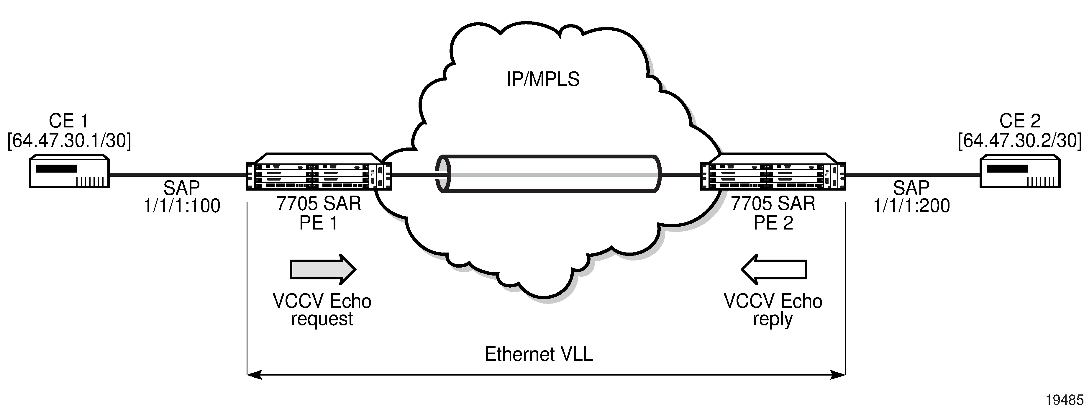
VCCV-based pseudowire (PW) tests are only supported on dynamically signaled PWs (not on statically signaled PWs).
There are three methods of encapsulating a VCCV message in a VLL, which translates into three types of control channels, as follows:
Type 1 — in-band VCCV (special control word)
Type 1 uses the OAM control word, which is shown in OAM Control Word Format.
Figure 16. OAM Control Word Format 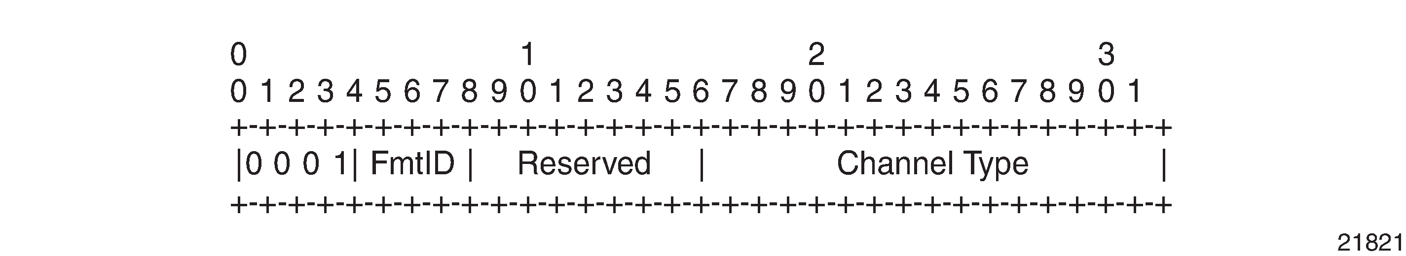
In OAM Control Word Format, the first nibble is set to 0x1. The Format ID and the Reserved fields are set to 0 and the Channel Type is the code point associated with the VCCV IP control channel, as specified in the PWE3 IANA registry [RFC 4446]. The channel type value of 0x21 indicates that the Associated Channel carries an IPv4 packet.
The use of the OAM control word assumes that the draft-martini control word is also used for the user packets. This means that if the control word is optional for a VLL and is not configured, the 7705 SAR PE node will only advertise the router alert label as the CC capability in the Label Mapping message.
This method is supported by the 7705 SAR.
Type 2 — out-of-band VCCV (router alert above the service label)
The 7705 SAR uses the router alert label immediately above the VC label to identify the VCCV ping message. This method has a drawback in that if ECMP is applied to the outer LSP label, such as the transport label, the VCCV message will not follow the same path as the user packets. This effectively means it will not troubleshoot the appropriate path.
This method is supported by the 7705 SAR when a 7750 SR node acts as an LSR in the core of the network. If a 7705 SAR acts as an LSR in the core of the network, the VCCV type 2 message will instead follow the data path.
Type 3 — TTL expiry VCCV (service label TTL = 1 and special control word)
This method is not supported by the 7705 SAR.
When sending the label mapping message for the VLL, PE1 and PE2 must indicate which of the above OAM packet encapsulation methods (that is, which control channel type) they support. This is accomplished by including an optional VCCV TLV in the PW FEC interface parameter field. The format of the VCCV TLV is shown in VCCV TLV.
The absence of the optional VCCV TLV in the Interface parameters field of the pseudowire FEC indicates that the PE has no VCCV capability.
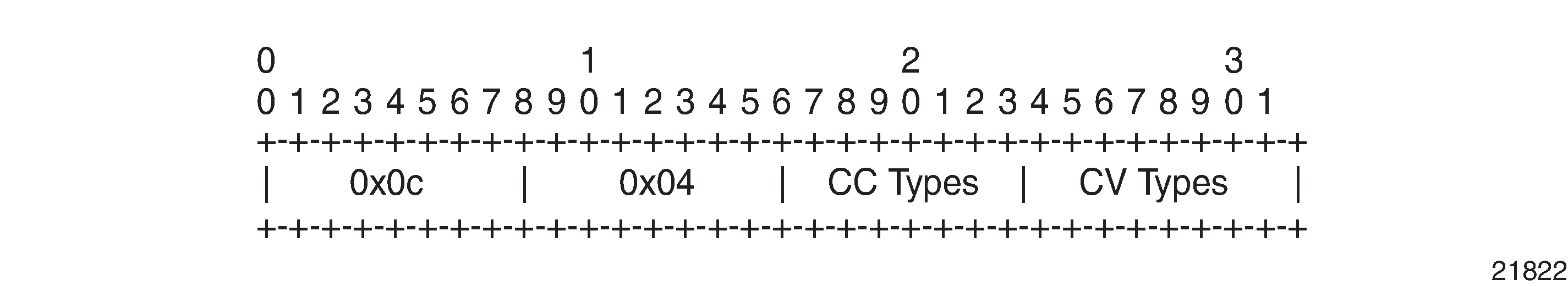
In VCCV TLV, the Control Channel (CC) Type field is a bit mask used to indicate if the PE supports none, one, or many control channel types:
0x00 — none of the following VCCV control channel types (Type 1, Type 2, or Type 3) are supported
0x01 — (Type 1, in-band) PWE3 OAM control word (see OAM Control Word Format)
0x02 — (Type 2, out-of-band) MPLS router alert label
0x04 — (Type 3, not supported on the 7705 SAR) MPLS inner label TTL = 1
If both PE nodes support more than one of the CC types, a 7705 SAR PE will make use of the CC type with the lowest type value. For instance, OAM control word (0x01) will be used in preference to the MPLS router alert label (0x02).
The Connectivity Verification (CV) Type field is a bit mask used to indicate the specific type of VCCV packets to be sent over the VCCV control channel. The possible values supported on the 7705 SAR are:
0x00 — none of the following VCCV packet types are supported
0x02 — LSP ping
This value (0x02) is used in the VCCV ping application and applies to a VLL over an MPLS, GRE, or IP SDP.
A VCCV ping is an LSP echo request message as defined in RFC 4379. It contains a Layer 2 FEC stack TLV in which it must include the sub-TLV type 10 FEC 128 pseudowire. It also contains a field that indicates to the destination PE which reply mode to use:
do not reply
This mode is supported by the 7705 SAR.
reply by an IPv4 UDP packet
This mode is supported by the 7705 SAR.
reply via an IPv4 UDP packet with router alert
This mode is not supported by the 7705 SAR.
Note: This mode, which sets the router alert bit in the IP header, should not be confused with the CC type that makes use of the router alert label.reply by application-level control channel
This mode sends the reply message in-band over the pseudowire from PE2 to PE1. PE2 will encapsulate the echo reply message using the CC type negotiated with PE1.
This mode is supported by the 7705 SAR.
The VCCV ping reply has the same format as an LSP echo reply message as defined in RFC 4379. The message is sent via the reply mode requested by PE1. The return codes supported are the same as those currently supported in the 7705 SAR LSP ping capability.
The VCCV ping feature is in addition to the service ping OAM feature that can be used to test a service between 7705 SAR nodes. The VCCV ping feature can test connectivity of a VLL with any third-party node that is compliant with RFC 5085.
VCCV Ping in a Multi-Segment Pseudowire
VCCV Ping Over a Multi-Segment Pseudowire displays an example of an application of VCCV ping over a multi-segment pseudowire (MS-PW). Pseudowire switching provides the user with the ability to create a VLL service by cross-connecting two spoke SDPs.
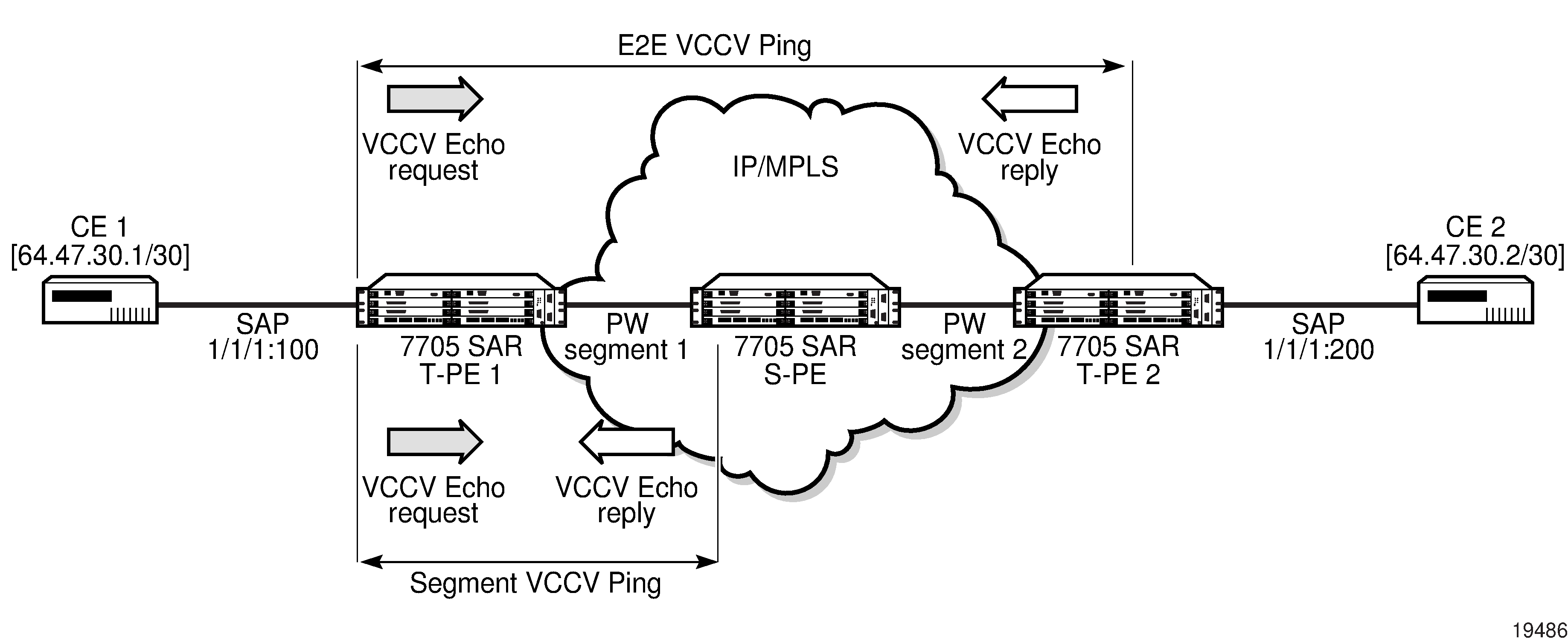
In the network, a Termination PE (T-PE) is where the pseudowire originates and terminates. The Switching PE (S-PE) is the node that performs pseudowire switching by cross-connecting two spoke SDPs.
VCCV ping on the 7705 SAR is capable of performing VCCV ping to a destination PE. A VLL FEC ping is a message sent by T-PE1 to test the FEC at T-PE2. The operation at T-PE1 and T-PE2 is the same as in the case of a single-segment pseudowire. The 7705 SAR pseudowire switching node, S-PE1, pops the outer label, swaps the inner (VC) label, decrements the TTL of the VC label, and pushes a new outer label. The 7705 SAR S-PE1 node does not process the VCCV OAM control word unless the VC label TTL expires. If the VC label TTL expires, the message is sent to the CSM for further validation and processing. This is the method described in draft-hart-pwe3-segmented-pw-vccv.
The originator of the VCCV ping message does not need to be a T-PE node; it can be an S-PE node. The destination of the VCCV ping message can also be an S-PE node. When an S-PE node receives a VCCV ping echo request destined for itself, it sends an IP-routed reply. VCCV trace can trace the entire path of a pseudowire with a single command issued at the T-PE. This is equivalent to LSP trace and is an iterative process, where T-PE1 sends successive VCCV ping messages while incrementing the TTL value, starting from TTL=1.
The procedure for each iteration is the same. Each node in which the VC label TTL expires checks the FEC and replies with the FEC to the downstream S-PE or T-PE node. The process is terminated when the reply is sent from the T-PE2 node or when a timeout occurs.
Automated VCCV Trace Capability for Multi-Segment Pseudowire
Although tracing of the MS-PW path is possible using the methods described in the VCCV Ping section, these require multiple manual iterations and that require the FEC of the last pseudowire segment to the target T-PE/S-PE already be known at the node originating the echo request message for each iteration. This mode of operation is referred to as a "ping" mode.
The automated VCCV trace can trace the entire path of a pseudowire with a single command issued at the T-PE or at an S-PE. This is equivalent to LSP trace and is an iterative process by which the ingress T-PE or T-PE sends successive VCCV ping messages with incrementing TTL values, starting from TTL=1.
The method is described in draft-hart-pwe3-segmented-pw-vccv, VCCV Extensions for Segmented Pseudo-Wire, and is pending acceptance by the PWE3 working group. In each iteration, the source T-PE or S-PE builds the MPLS echo request message in a way similar to VCCV Ping. The first message with TTL=1 will have the next-hop S-PE T-LDP session source address in the Remote PE Address field in the pseudowire FEC TLV. Each S-PE that terminates and processes the message will include the FEC 128 TLV corresponding to the pseudowire segment to its downstream node, in the MPLS echo reply message. The inclusion of the FEC TLV in the echo reply message is allowed according to RFC 4379, Detecting Multi-Protocol Label Switched (MPLS) Data Plane Failures.
The source T-PE or S-PE then sends the next echo reply message with TTL=2 to test the next-next hop for the MS-PW. It copies the FEC TLV it received in the echo reply message into the new echo request message. The process is terminated when the reply is sent from the egress T-PE node or when a timeout occurs. If specified, the max-ttl parameter in the vccv-trace command will stop on SPE before reaching T-PE.
The results of VCCV trace can be displayed for fewer pseudowire segments of the end-to-end MS-PW path. In this case, the min-ttl and max-ttl parameters are configured accordingly. However, the T-PE/S-PE node will still probe all hops up to the min-ttl value in order to correctly build the FEC of the required subset of segments.
This method does not require the use of the downstream mapping TLV in the echo request and echo reply messages.
VCCV for Static Pseudowire Segments
MS-PW is supported with a mix of static and signaled pseudowire segments. However, VCCV ping and VCCV trace are not allowed if any segment of the MS-PW is static. Users cannot test a static segment or contiguous signaled segments of the MS-PW. VCCV ping and VCCV trace are not supported in static-to-dynamic configurations.
VCCV for MS-PW and Pseudowire Redundancy
VCCV is supported on S-PE nodes configured for MS-PW and PW redundancy. In this case, S-PE terminates the in-band or out-of-band (IP-routed) VCCV ping (echo reply) and can generate VCCV ping (echo request) toward the dynamic section of the PW segment.
To configure an S-PE for MS-PW and pseudowire redundancy, an explicit endpoint is required to configure the service. Only one explicit endpoint is supported. The first PW segment must be configured with a static inner label under an implicit endpoint. The second PW segment can be created as either a redundant or non-redundant PW using the explicit endpoint.
On S-PE nodes configured for MS-PW and PW redundancy, each segment of the PW can be configured with its own independent control word. The control word of the dynamic segment does not have to match the control word of the static segment for traffic to flow. The control word is automatically inserted or removed from the packets as they are switched from one segment to the other based on the control word configuration for each segment.
From an OAM diagnostic perspective, only Type-1 VCCV is supported for the dynamic MS-PW segment, which means that the PW segment must be configured with the control word option. In this mode, the ability to support VCCVs is signaled through the label message and the optional VCCV TLV toward the dynamic segment on the S-PE. The S-PE terminates all VCCV packets arriving on the dynamic segment, then extracts them toward the CSM.
Detailed VCCV Trace Operation
In VCCV Ping Over a Multi-Segment Pseudowire, a trace can be performed on the MS-PW originating from T-PE1 by a single operational command. The following process occurs:
T-PE 1 sends a VCCV echo request with TTL set to 1 and a FEC 128 containing the pseudowire information of the first segment (pseudowire1 between T-PE 1 and S-PE) to S-PE for validation.
S-PE validates the echo request with the FEC 128. Since it is a switching point between the first and second segment, it builds an echo reply with a return code of 8 and includes the FEC 128 of the second segment (pseudowire2 between S-PE and T-PE 2) and sends the echo reply back to T-PE 1.
T-PE 1 builds a second VCCV echo request based on the FEC 128 in the echo reply from the S-PE. It increments the TTL and sends the next echo request out to T-PE 2. The VCCV echo request packet is switched at the S-PE datapath and forwarded to the next downstream segment without any involvement from the control plane.
T-PE 2 receives and validates the echo request with the FEC 128 of the pseudowire2 from TPE 1. Since T-PE 2 is the destination node or the egress node of the MS-PW, it replies to T-PE1 with an echo reply with a return code of 3 (egress router) and no FEC 128 is included.
T-PE 1 receives the echo reply from T-PE 2. T-PE 1 is made aware that T-PE 2 is the destination of the MS-PW because the echo reply does not contain the FEC 128 and because its return code is 3. The trace process is completed.
VCCV Trace
VCCV trace is similar to LSP trace. VCCV trace is used to trace the entire path of a pseudowire (PW) with a single command.
VCCV trace is useful in multi-segment PW (MS-PW) applications where a single PW traverses one or more switched PEs (S-PEs). VCCV trace is an iterative process by which the initiating terminating PE (T-PE) sends successive VCCV ping messages, each message having an incrementing TTL value, starting from TTL=1. The procedure for each iteration is the same as that for VCCV-ping, where each node in which the VC label TTL expires will check the FEC and reply with the FEC to the downstream S-PE or far-end T-PE. The process is terminated when the reply is from the far-end T-PE or when a timeout occurs.
The results of a VCCV trace can be displayed for fewer pseudowire segments of the end-to-end MS-PW path. In this case, the min-ttl and max-ttl parameters should be configured accordingly. However, the T-PE or S-PE will still probe all hops up to the min-ttl value in order to correctly build the FEC of the desired subset of segments.
ITU-T Y.1564 Diagnostics
The 7705 SAR supports the ITU-T Y.1564 feature for throughput and bandwidth testing of Ethernet point-to-point virtual circuits. ITU-T Y.1564 includes, but also improves and standardizes, the RFC 2544 testing process.
ITU-T Y.1564 is supported on second-generation Ethernet ports in access mode in conjunction with 16-priority scheduling, on the following:
7705 SAR-A
7705 SAR-Ax
7705 SAR-H (not supported on the 4-port SAR-H Fast Ethernet module)
7705 SAR-Hc
7705 SAR-M
7705 SAR-Wx
8-port Gigabit Ethernet Adapter card
10-port 1GigE X-Adapter card (in 10-port 1GigE mode)
Packet Microwave Adapter card
ITU-T Y.1564 is supported on third-generation Ethernet ports in access mode in conjunction with 4-priority scheduling, on the following:
7705 SAR-X
6-port Ethernet 10Gbps Adapter card
For information about card and platform generations, see the 7705 SAR Interface Configuration Guide, "Evolution of Ethernet Adapter Cards, Modules, and Platforms".
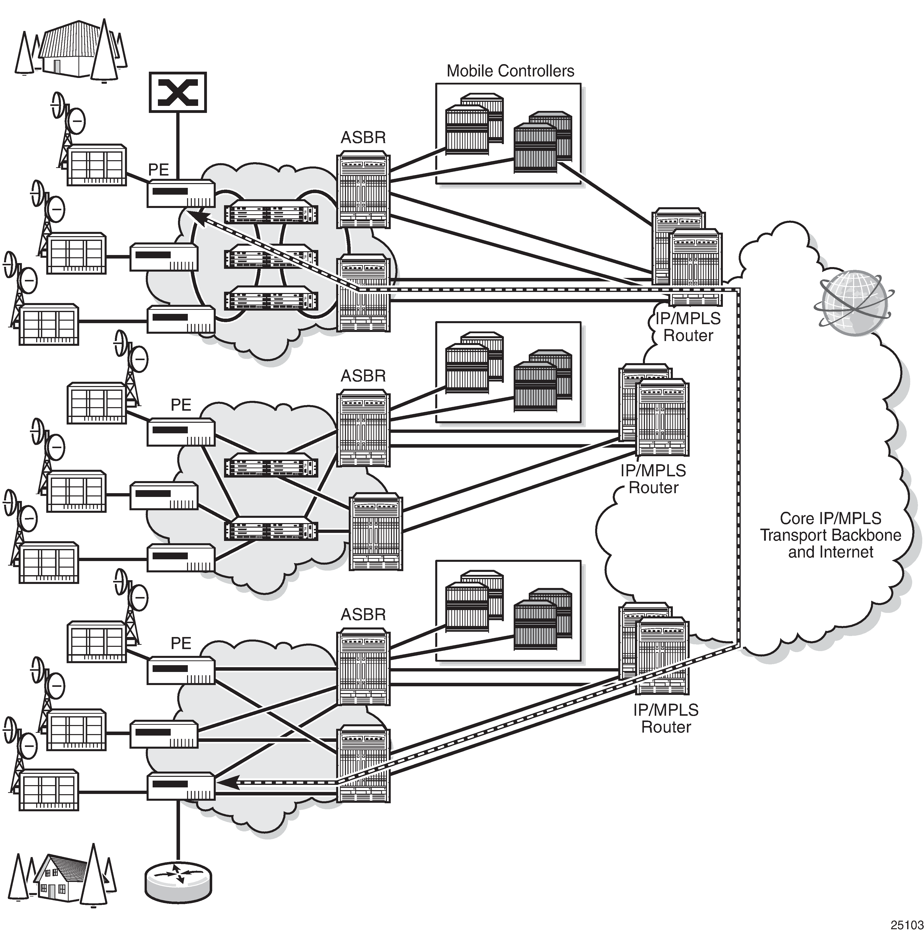
In a traditional hub and spoke network model, traffic is terminated on edge routers and aggregation hubs, which also perform bandwidth and throughput tests. In a flat, seamless, MPLS network, edge routers and aggregation hubs provide only forwarding and switching and cannot be used for service testing as they do not terminate traffic.
ITU-T Y.1564 is crucial in these types of networks because it provides the 7705 SAR edge nodes with the ability to run a complete validation of Ethernet SLAs. The 7705 SAR generates RFC 2544 test frames, up to the required rate, and sends them through the SAP of the service to test its performance. The far-end nodes must also offer per-service loopback capabilities, with the epipe>sap>loopback command, to return the traffic to the source node for test analysis and reporting.
ITU-T Y.1564 End-to-End Throughput Test shows a network with service endpoints where throughput tests are required.
During an ITU-T Y.1564 test, marker frames are used to measure delay and jitter. Packet loss is reported directly by counting transmitted and received frames. Delay, jitter, and loss support two profile states: conforming traffic (configured as in-profile) and non-conforming traffic (configured as out-of-profile).
The 7705 SAR relies on the SAP ingress and SAP egress QoS profile queuing points for generated test traffic bandwidth. The assigned CIR and PIR dictate the potential test frame coloring when a Y.1564 test is run with color-aware enabled.
The following colors are assigned to packets:
green — traffic is equivalent to the CIR
yellow — traffic received, up to the SAP PIR provisioned value
red — traffic exceeding the PIR provisioned value
Queuing and Policing Points That Impact Throughput shows all of the queuing and policing points, in addition to the SAP ingress QoS profile, that can have an effect on the throughput test results. Each of these queuing points can contribute to traffic policing or shaping, which can impact delay, jitter, and loss measurements.
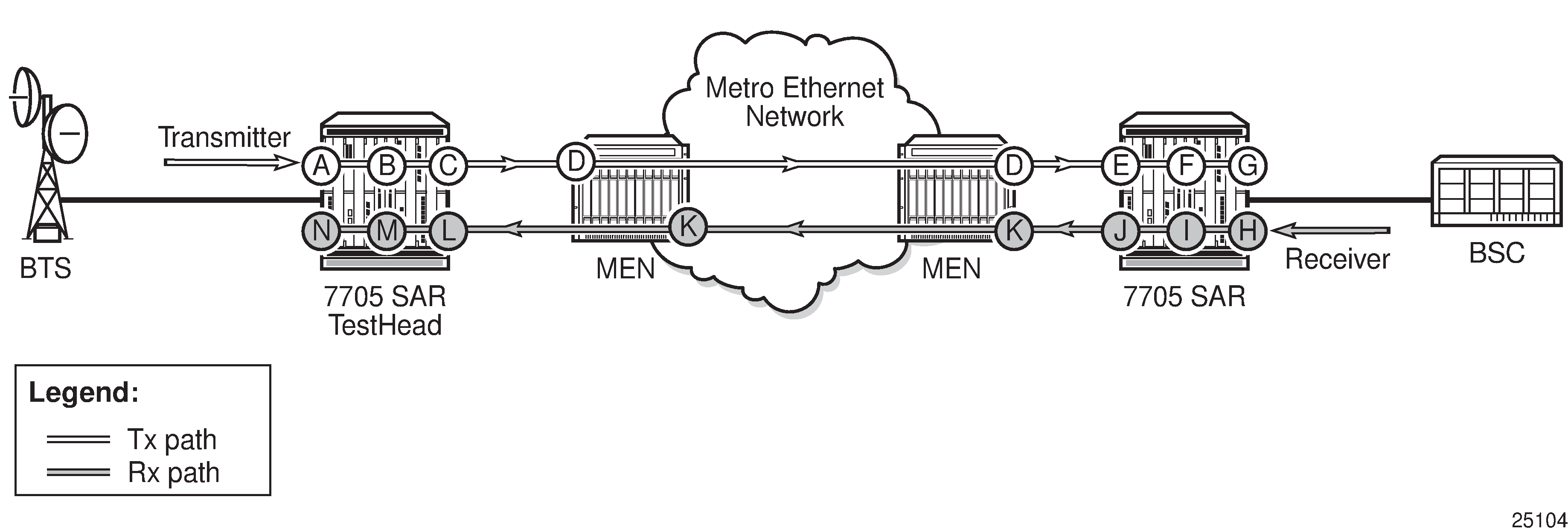
| Point | Description | Point | Description |
|---|---|---|---|
|
A |
Test head access/SAP ingress QoS profile |
H |
Far-end/responder access/SAP ingress QoS profile |
|
B |
Test head access ingress fabric shaper |
I |
Far-end/responder access ingress fabric shaper |
|
C |
Test head network egress QoS profile |
J |
Far-end/responder network egress QoS profile |
|
D |
Any QoS enforcement via intermediate LSR nodes |
K |
Any QoS enforcement via intermediate LSR nodes |
|
E |
Far-end/responder network ingress QoS profile |
L |
Test head network ingress QoS profile |
|
F |
Far-end/responder network ingress fabric shaper |
M |
Test head network ingress fabric shaper |
|
G |
Far-end/responder access/SAP egress QOS profile |
N |
Test head access/SAP egress QoS profile |
ITU-T Y.1564 Functionality
The 7705 SAR supports the test heads, as defined in RFC 2544, for ITU-T Y.1564. Test heads allow users to configure a set of trusted procedures to use during testing.
An ITU-T Y.1564 test head cannot survive activity switches (on platforms supporting HA), or any maintenance operation at the port, SAP, service level. The user must restart the test from the newly active CSM. If an activity switch occurs during an active test, all statistics and measurement data are lost.
An Ethernet SAP loopback can survive a CSM activity switch if it is enabled with the persistent keyword. Otherwise, the loopback is also reset during an activity switch. Ethernet SAP loopbacks are supported on LAG and MC-LAG ports on second-generation and third-generation Ethernet cards.
ITU-T Y.1564 test heads rely on delay and delay variation when calculating jitter. For more details, see RFC 3550, section A.8.
Users can configure the following frame type using the frame-payload command: Layer 2 payload, IPv4 payload, and IP/TCP/UDP payload. The test head uses the configured values for the IP header fields and TCP header fields based on the payload type configured.
The test head implementation on the 7705 SAR allows users to run tests with up to four parallel flows by specifying up to four frame payload IDs in the oam>testhead command. This allows users to test a service with IMIX-type traffic patterns.
ITU-T Y.1564 Protocol Interaction
CFM OAM must be explicitly disabled in order for an ITU-T Y.1564 test or Ethernet SAP loopback to be operational. You can enable a Y.1564 test head or Ethernet SAP loopback, or enable CFM OAM, but not both simultaneously (see ITU-T Y.1564 Protocol Interaction).
Feature |
Y.1564 Test Head |
Ethernet SAP Loopback |
||
|---|---|---|---|---|
Line |
Internal |
Line |
Internal |
|
All Layer 1 peering functionality (EFM (excluding tunneling), LLDP, SSM, EAP, and down-when-looped) |
Maintained |
— |
Maintained |
— |
EFM tunneling |
Dropped |
— |
Dropped |
— |
802.1ag Y.1731 CFM |
— |
Must be explicitly disabled |
— |
Must be explicitly disabled |
BFD |
— |
— |
— |
— |
VPLS MAC Diagnostics
Although the LSP ping, SDP ping, and service ping tools enable transport tunnel testing and verify that the correct transport tunnel is used, they do not provide the means to test the learning and forwarding functions on a per-VPLS service basis.
It is possible that even though tunnels are operational and correctly bound to a service, an incorrect Forwarding Information Base (FIB) table for a service could cause connectivity issues in the service and not be detected by the ping tools. The 7705 SAR provides VPLS OAM functionality to specifically test all the critical functions on a per-service basis. These tools are based primarily on the IETF document draft-stokes-vkompella-ppvpn-hvpls-oam-xx.txt, Testing Hierarchical Virtual Private LAN Services.
The VPLS OAM tools are:
MAC Ping — an end-to-end test to identify the egress customer-facing port where a customer MAC was learned. MAC ping can also be used with a broadcast MAC address to identify all egress points of a service for the specified broadcast MAC.
MAC Trace — the ability to trace a specified MAC address hop-by-hop until the last node in the service domain. An SAA test with MAC trace is considered a successful OAM and SAA test when there is a reply from a far-end node indicating the destination MAC address on an egress SAP or the CSM.
CPE Ping — the ability to check network connectivity to the specified client device within the VPLS. CPE ping will return the MAC address of the client, as well as the SAP and PE from which it was learned.
MAC Populate — allows specified MAC addresses to be injected in the VPLS service domain. This triggers learning of the injected MAC address by all participating nodes in the service. This tool is generally followed by MAC ping or MAC trace to verify if correct learning occurred.
MAC Purge — allows MAC addresses to be flushed from all nodes in a service domain
MAC Ping
For a MAC ping test, the destination MAC address (unicast or multicast) to be tested must be specified. A MAC ping packet can be sent through the control plane or the data plane. When sent by the control plane, the ping packet goes directly to the destination IP in a UDP/IP OAM packet. When it is sent by the data plane, the ping packet goes out with the data plane format.
In the control plane, a MAC ping is forwarded along the flooding domain if no MAC address bindings exist. If MAC address bindings exist, then the packet is forwarded along those paths (if they are active). Finally, a response is generated only when there is an egress SAP binding to that MAC address. A control plane request is responded to via a control reply only.
In the data plane, a MAC ping is sent with a VC label TTL of 255. This packet traverses each hop using forwarding plane information for next hop, VC label, and so on. The VC label is swapped at each service-aware hop, and the VC TTL is decremented. If the VC TTL is decremented to 0, the packet is passed up to the management plane for processing. If the packet reaches an egress node, and would be forwarded out a customer-facing port, it is identified by the OAM label below the VC label and passed to the management plane.
MAC pings are flooded when they are unknown at an intermediate node. They are responded to only by the egress nodes that have mappings for that MAC address.
A 7705 SAR node using GNSS or IEEE 1588v2 PTP for time of day/phase recovery can perform MAC ping tests with high-accuracy timestamping. See the 7705 SAR Basic System Configuration Guide, "Node Timing", for information about node timing sources.
MAC Trace
A MAC trace operates like an LSP trace with variations. Operations in a MAC trace are triggered when the VC TTL is decremented to 0.
Like a MAC ping, a MAC trace can be sent either by the control plane or the data plane.
When a MAC trace request is sent by the control plane, the destination IP address is determined from the control plane mapping for the destination MAC. If the destination MAC is known to be at a specific remote site, then the far-end IP address of that SDP is used. If the destination MAC is not known, then the packet is sent as a unicast transmission to all SDPs in the service with the appropriate squelching.
A control plane MAC traceroute request is sent via UDP/IP. The destination UDP port is the LSP ping port. The source UDP port is assigned by the system, where the source UDP port is really the demultiplexer that identifies the particular instance that sent the request, when that demultiplexer correlates the reply. The source IP address is the system IP address of the sender.
When a traceroute request is sent via the data plane, the data plane format is used. The reply can be via the data plane or the control plane.
A data plane MAC traceroute request includes the tunnel encapsulation, the VC label, and the OAM, followed by an Ethernet DLC, a UDP, and IP header. If the mapping for the MAC address is known at the sender, then the data plane request is sent down the known SDP with the appropriate tunnel encapsulation and VC label. If it is not known, then it is sent down every SDP (with the appropriate tunnel encapsulation per SDP and appropriate egress VC label per SDP binding).
The tunnel encapsulation TTL is set to 255. The VC label TTL is initially set to the min-ttl (default is 1). The OAM label TTL is set to 2. The destination IP address is the all-routers multicast address. The source IP address is the system IP address of the sender.
The Reply Mode is either 3 (control plane reply) or 4 (data plane reply), depending on the reply-control option. By default, the data plane request is sent with Reply Mode 3 (control plane reply).
The Ethernet DLC header source MAC address is set to either the system MAC address (if no source MAC is specified) or to the specified source MAC. The destination MAC address is set to the specified destination MAC. The Ethertype is set to IP.
CPE Ping
The MAC ping OAM tool makes it possible to detect whether a particular MAC address has been learned in a VPLS.
The cpe-ping command extends this capability and can detect end-station IP addresses inside a VPLS. A CPE ping for a specific destination IP address within a VPLS will be translated to a MAC ping towards a broadcast MAC address. Upon receiving such a MAC ping, each peer PE within the VPLS context will trigger an ARP request for the specific IP address. The PE receiving a response to this ARP request will report back to the requesting 7705 SAR. Operators are encouraged to use the source IP address of 0.0.0.0 in order to prevent the provider's IP address from being learned by the CE.
MAC Populate
MAC populate is used to send a message through the flooding domain to learn a MAC address as if a customer packet with that source MAC address had flooded the domain from that ingress point in the service. This allows the provider to craft a learning history and engineer packets in a particular way to test forwarding plane correctness.
The MAC populate request is sent with a VC TTL of 1, which means that it is received at the forwarding plane at the first hop and passed directly up to the management plane. The packet is then responded to by populating the MAC address in the forwarding plane, like a conventional learn, although the MAC will be an OAM-type MAC in the FIB to distinguish it from customer MAC addresses.
This packet is then taken by the control plane and flooded out the flooding domain (squelching appropriately, the sender and other paths that would be squelched in a typical flood).
This controlled population of the FIB is very important to manage the expected results of an OAM test. The same functions are available by sending the OAM packet as a UDP/IP OAM packet. It is then forwarded to each hop and the management plane has to do the flooding.
Options for MAC populate are to force the MAC in the table to type OAM (in case it already existed as dynamic or static or as an OAM-induced learning with some other binding), to prevent new dynamic learning to over-write the existing OAM MAC entry, or to allow customer packets with this MAC to either ingress or egress the network while still using the OAM MAC entry.
Finally, an option to flood the MAC populate request causes each upstream node to learn the MAC, for example, to populate the local FIB with an OAM MAC entry, and to flood the request along the data plane using the flooding domain.
An age can be provided to age a particular OAM MAC after a different interval than other MACs in a FIB.
MAC Purge
MAC purge is used to clear the FIBs of any learned information for a particular MAC address. This allows an operator to perform a controlled OAM test without learning induced by customer packets. In addition to clearing the FIB of a particular MAC address, the purge can also indicate to the control plane not to allow further learning from customer packets. This allows the FIB to be clean and be populated only via a MAC populate request.
MAC purge follows the same flooding mechanism as the MAC populate. A UDP/IP version of this command is also available that does not follow the forwarding notion of the flooding domain, but rather the control plane behavior of it.
Ethernet OAM Capabilities
The 7705 SAR supports Ethernet OAM capabilities, as described in the following sections:
Ethernet OAM Overview
The 7705 SAR supports the following Ethernet OAM capabilities:
Ethernet Connectivity Fault Management (ETH-CFM) — for network layer OAM according to IEEE 802.1ag (dot1ag) and ITU Y.1731 standards, including loopback (LB), linktrace (LT), continuity check (CC), and remote defect indication (RDI). "Network layer" refers to an end-to-end context across a network.
ITU-T Y.1731 provides functional enhancements to 802.1ag ETH-CFM, including alarm indication signals (AIS) and Ethernet signal tests (ETH-Test).
Performance Monitoring (PM) — PM according to the ITU-T Y.1731 standard, including delay measurements (DM), delay variation measurements (DV), and loss measurements (LM)
Ethernet Bandwidth Notification (ETH-BN) — when enabled on a port, the egress rate may be dynamically altered based on the available bandwidth indicated by the ETH-BN server.
Ethernet First Mile (EFM) OAM — for the transport layer OAM according to IEEE 802.3ah (dot3ah) standards. "Transport layer" refers to a point-to-point link context or transport hop.
See EFM OAM (802.3ah).
Ethernet OAM capabilities on the 7705 SAR are similar to the OAM capabilities offered in SONET/SDH networks and include loopback tests to verify end-to-end connectivity, test pattern generation (and response) to verify error-free operation, and alarm message generation in case of fault conditions to ensure that the far end is notified of the failure.
Ethernet OAM configurations are maintained across CSM switchovers.
Ethernet OAM Usage Examples
7705 SAR Ethernet OAM Endpoints illustrates the complementary use of dot3ah and dot1ag to locate points of failure along a route from BTS to BSC. Because dot1ag and Y.1731 have similar functions, only dot1ag is discussed in order to simplify the explanation.
In 7705 SAR Ethernet OAM Endpoints, from the IP/MPLS (network) layer perspective, the 7705 SAR looks as though it is connected directly to the 7750 SR. From the Ethernet (transport) layer perspective, the route passes through many ports and nodes, where each port or node is a potential point of failure. These failure points cannot be detected using IP/MPLS OAM capabilities (that is, using ETH-CFM (dot1ag)). However, they can be detected using EFM OAM (dot3ah) capabilities.
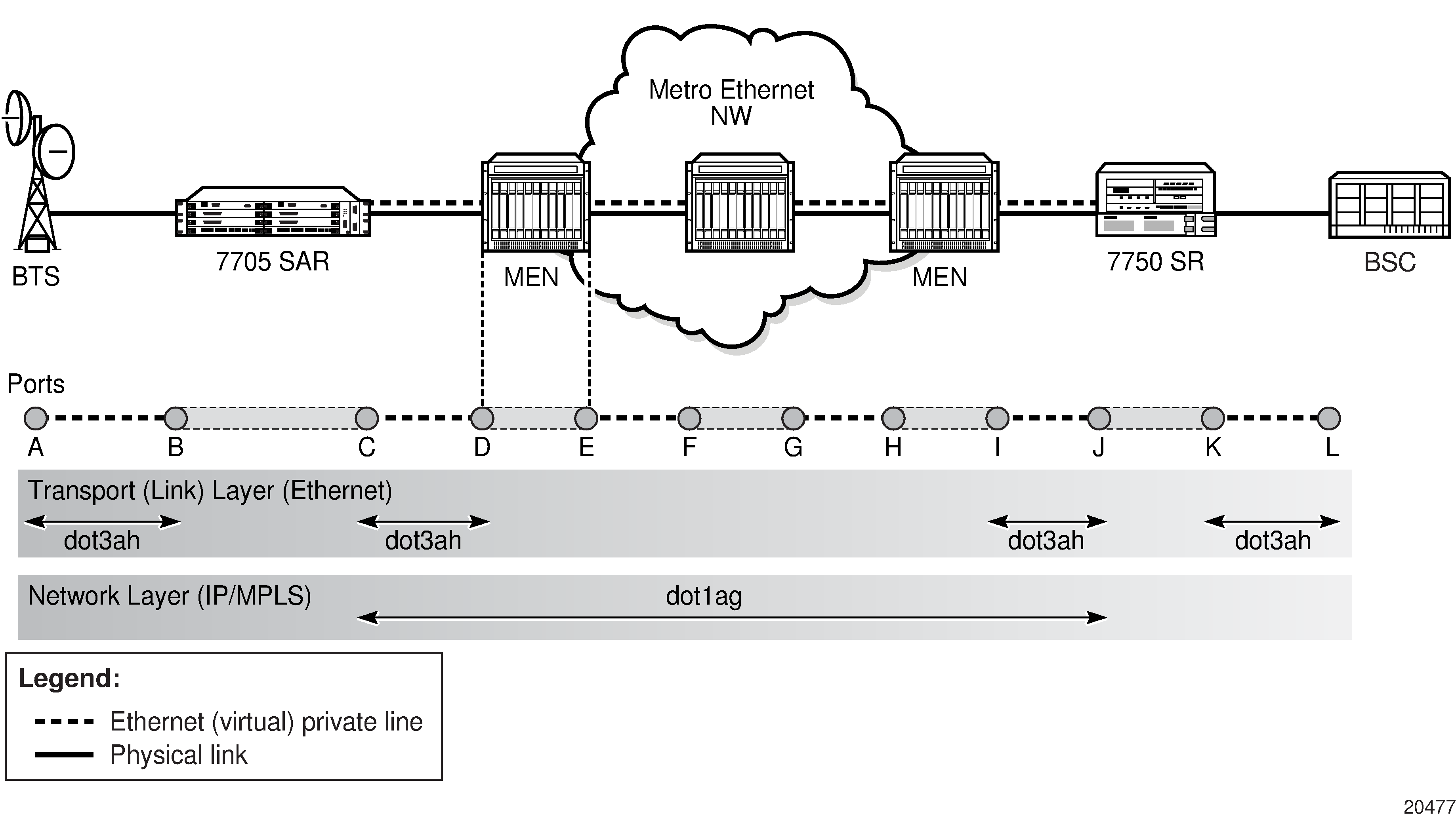
Dot3ah uses port-level loopbacks to check and verify last-mile Ethernet frame integrity, connectivity verification between ports and nodes, and so on. As shown in 7705 SAR Ethernet OAM Endpoints, dot3ah provides transport (link) layer OAM between the BTS and the 7705 SAR access port facing the BTS (ports A and B), or between the 7705 SAR network port and the MEN switch (ports C and D). Ethernet first mile (EFM) OAM allows users to test frame integrity and detect Ethernet layer failures faster than using associated heartbeat messages.
Dot1ag checks end-to-end connectivity across an Ethernet PW (across a network). Because end-to-end connectivity differs depending on the service provided and the span of the network, dot1ag can operate at several MD levels (as defined in the IEEE 802.1ag standard). For example, in 7705 SAR Ethernet OAM Endpoints, ETH-CFM (dot1ag) could be used by a MEN provider at one MD level to ensure connectivity between ports D and I (or possibly all the way to their customer's Ethernet ports, C and J). Similarly, a mobile backhaul service provider (MBSP) can use dot1ag at another MD level to ensure connectivity between ports B and K (and possibly between ports A and L).
ETH-CFM (Dot1ag) Capabilities on the 7705 SAR and EFM OAM (Dot3ah) Capabilities on the 7705 SAR illustrate the use of ETH-CFM to verify connectivity across an Ethernet PW and EFM OAM to verify transport layer connectivity between two directly connected nodes.
For example, in ETH-CFM (Dot1ag) Capabilities on the 7705 SAR, an MBSP can use dot1ag between the two Ethernet spoke SDP endpoints (ports C and J, which define the Ethernet PW) to ensure connectivity. Similarly, a MEP can use dot1ag between ports D and I to ensure the health status of the Ethernet (virtual) private line.
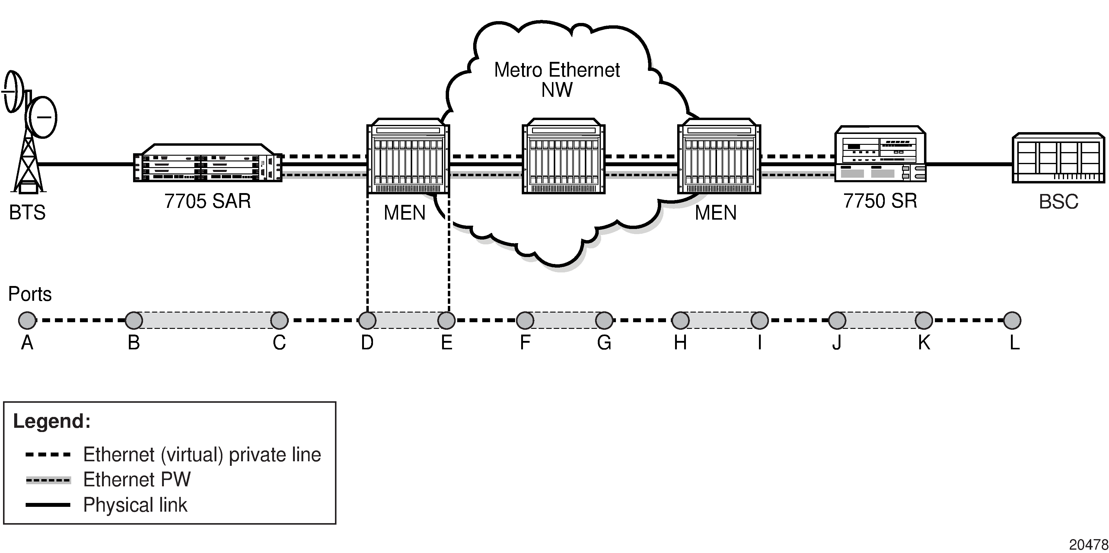
In EFM OAM (Dot3ah) Capabilities on the 7705 SAR, EFM OAM ensures transport layer connectivity between two directly connected nodes. EFM OAM (Dot3ah) Capabilities on the 7705 SAR illustrates three scenarios in which EFM can be used by the MEN provider to ensure error-free connectivity to the 7705 SAR (the cell site) via loopback tests, including:
scenario 1: EFM termination at the Ethernet access port, which includes loopback tests, heartbeat messages at the Ethernet layer with dying gasp, and termination of customer device-initiated EFM packets at the access port
scenario 2: EFM termination at the Ethernet network port, which includes network-side loopbacks
scenario 3: EFM tunneling through an Epipe service
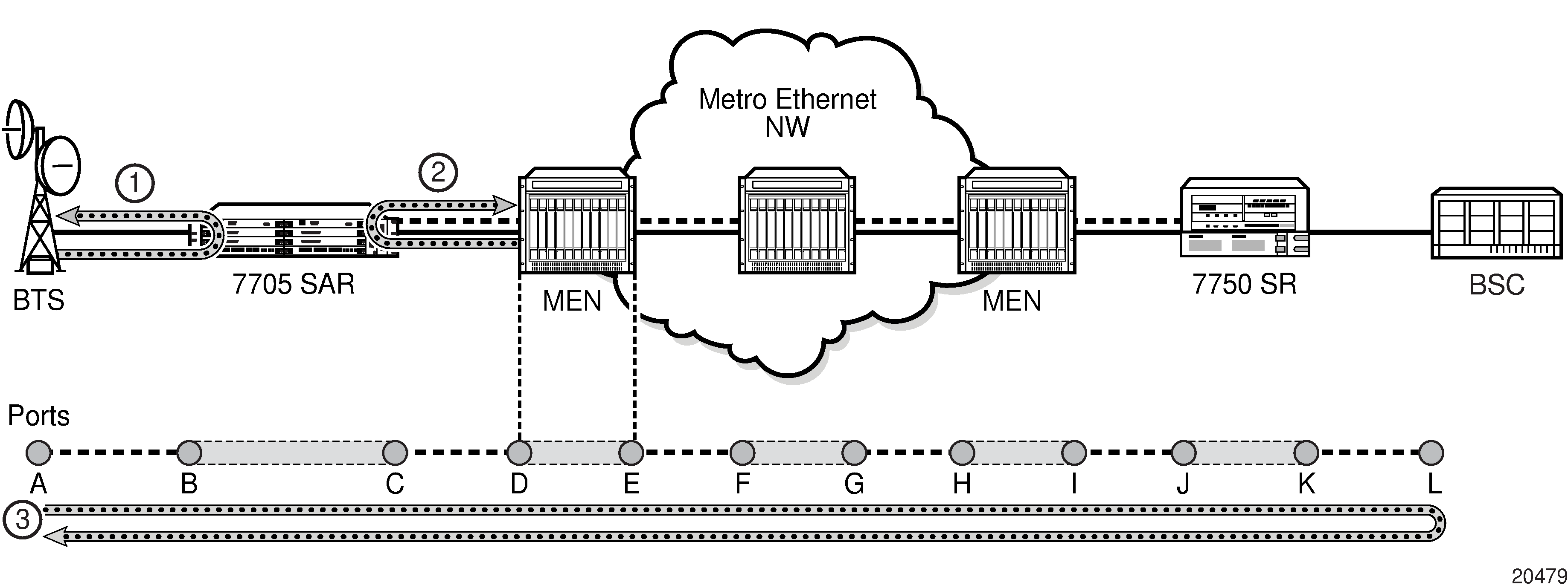
802.1ag and Y.1731 Functional Comparison
802.1ag and Y.1731 OAM Functionality Overview lists the 802.1ag and Y.1731 OAM functions supported on the 7705 SAR. For each function and test, the table identifies the PDU that carries the test data, the test’s target entity, and the standards that the 7705 SAR supports for the test.
For example, the 7705 SAR can run an Ethernet Continuity Check using an ETH-CC test according to the dot1ag and the Y.1731 standards. For either standard, the test data is carried in a Continuity Check Message (CCM) and the test target is a MEP.
The Fault Management (FM) capabilities of ITU-T Y.1731 extend the functionality of dot1ag (ETH-CFM) with additional FM functions as well as performance monitoring (PM) capabilities. The generation of AIS and RDI messages are defined under the FM section of the Y.1731 specification, whereas Ethernet layer, delay, jitter, loss, and throughput tests are part of Y.1731 PM capabilities.
Supported OAM Tests per MEP Type lists the MEPs that support each test.
Test |
OAM function |
PDU |
Target |
Standard |
|---|---|---|---|---|
ETH-LB |
Loopback |
LBM, LBR |
MEP |
dot1ag, Y.1731 |
ETH-LT |
Linktrace |
LTM, LTR |
MEP |
dot1ag, Y.1731 |
ETH-CC |
Continuity Check |
CCM |
MEP |
dot1ag, Y.1731 |
ETH-RDI |
Remote Defect Indication |
CCM |
MEP |
dot1ag, Y.1731 |
ETH-AIS |
Alarm Indication Signal |
AIS |
MEP |
Y.1731 |
ETH-LM |
Frame Loss Measurement (dual-ended) |
CCM |
MEP |
Y.1731 |
ETH-LM |
Frame Loss Measurement (single-ended) |
LMM, LMR |
MEP |
Y.1731 |
ETH-DM |
Frame Delay Measurement (two-way) |
DMM, DMR |
MEP |
Y.1731 |
ETH-DM |
Frame Delay Measurement (one-way) |
1DM |
MEP |
Y.1731 |
ETH-DV |
Frame Delay Variation (one-way) |
DMM, DMR |
MEP |
Y.1731 |
ETH-Test |
Test Error Measurements |
TST |
MEP |
Y.1731 |
ETH-SL |
Synthetic Loss Measurement |
SLM |
MEP |
dot1ag, Y.1731 |
OAM Test |
Epipe SAP Up/Down MEP |
Epipe Spoke SDP Up/Down MEP |
VPLS SAP Up/Down MEP |
VPLS Spoke/Mesh SDP Up/Down MEP |
Ethernet Network Interface Down MEP (Facility) |
|---|---|---|---|---|---|
Loopback |
✓ |
✓ |
✓ |
✓ |
✓ |
Linktrace |
✓ |
✓ |
✓ |
✓ |
✓ |
Throughput Measurement |
✓ |
✓ |
✓ |
✓ |
✓ |
Continuity Check |
✓ |
✓ |
✓ |
✓ |
✓ |
Remote Defect Indication |
✓ |
✓ |
✓ |
✓ |
✓ |
Alarm Indication Signal |
✓ |
✓ |
|||
Test Error Measurements |
✓ |
✓ |
✓ |
||
Frame Delay Measurement (two-way) |
✓ |
✓ |
✓ |
✓ |
✓ |
Frame Delay Measurement (one-way) |
✓ |
✓ |
✓ |
✓ |
✓ |
Frame Delay Variation (one-way) |
✓ |
✓ |
✓ |
||
Frame Loss Measurement (dual-ended) |
✓ |
✓ |
|||
Frame Loss Measurement (single-ended) |
✓ |
✓ |
✓ |
||
Synthetic Loss Measurement |
✓ |
✓ |
✓ |
✓ |
✓ |
ETH-CFM Ethernet OAM Tests (802.1ag and Y.1731)
Ethernet Connectivity Fault Management (ETH-CFM) is defined in the IEEE 802.1ag and ITU Y.1731 standards. ETH-CFM specifies protocols, procedures, and managed objects to support fault management (including discovery and verification of the path), detection, and isolation of a connectivity fault in an Ethernet network.
IEEE 802.1ag and Y.1731 can detect:
loss of connectivity
unidirectional loss
loops
merging of services
The implementation of Y.1731 on the 7705 SAR also provides the following enhancements:
Ethernet Alarm Indication Signal (ETH-AIS)
Ethernet Test function (ETH-Test)
ETH-CFM uses Ethernet frames and can be distinguished by its Ethertype value (8902). With ETH-CFM, interoperability can be achieved between different vendor equipment in the service provider network, up to and including customer premises bridges.
ETH-CFM is configured at the global level and at the Ethernet service level (Epipes and VPLS) or network interface level. The following entities and their configuration levels are listed below:
global level
MA and MEG
MD
MD level and MEG level
Ethernet service level
MEP
Ethernet network interface level
facility MEP
For information about configuring ETH-CFM to set up an Ethernet OAM architecture, see the 7705 SAR Services Guide, "ETH-CFM (802.1ag and Y.1731)". Most of the configuration information applies to Ethernet network interfaces as well; for information about ETH-CFM support specific to network interfaces,see the 7705 SAR Router Configuration Guide, "ETH-CFM Support".
Hold MEP Up On Failure
The hold MEP up on failure function allows MEP operation that is independent of SAP status. In order to report service-level agreement (SLA) metrics, transport providers run Y.1731 performance monitoring tests periodically. At preset times, transport providers initiate various tests to measure and record one or all required SLA components: jitter, delay, loss, and throughput. The ability to hold MEP up allows the MEP to be kept in operation even if the SAP is down or non-operational.
The hold MEP up on failure function applies only to Ethernet pseudowire services (Epipes) operating between SAPs or between SAPs and SDPs. The SAP connecting the provider equipment to the customer can be configured to hold the MEP in operation when the customer-facing SAP enters any failed state. Only one SAP per Epipe can be configured in this manner. Pseudowire status will indicate a failed SAP in the LDP status message, but as long as the pseudowire is in an operationally up state, it supports receiving frames from the network's far-end side. Counters are also incremented to accurately represent the number of received packets.
ETH-CFM PM measurements, ETH-CFM troubleshooting tools and connectivity, and ETH-CFM CCM processing and fault propagation are not impacted by this feature and continue to function normally.
Loopback (ETH-LB)
The loopback function is supported by 802.1ag and Y.1731 on the 7705 SAR. A Loopback Message (LBM) is generated by a MEP to its peer MEP. Both dot1ag and dot3ah loopbacks are supported. The loopback function is similar to IP or MPLS ping in that it verifies Ethernet connectivity between the nodes on a per-request basis. That is, it is non-periodic and is only initiated by a user request.
In Dot1ag Loopback Test, the line labeled LB represents the dot1ag loopback message between the 7750 SR (source) and 7705 SAR (target) over an Ethernet PW (Epipe). The 7750 SR-generated LBM is switched to the 7705 SAR, where the LBM is processed. After the 7705 SAR generates the Loopback Reply message (LBR), the LBR is switched over the Epipe to the 7750 SR.
ETH-LB tests are run using the oam>eth-cfm>loopback command.
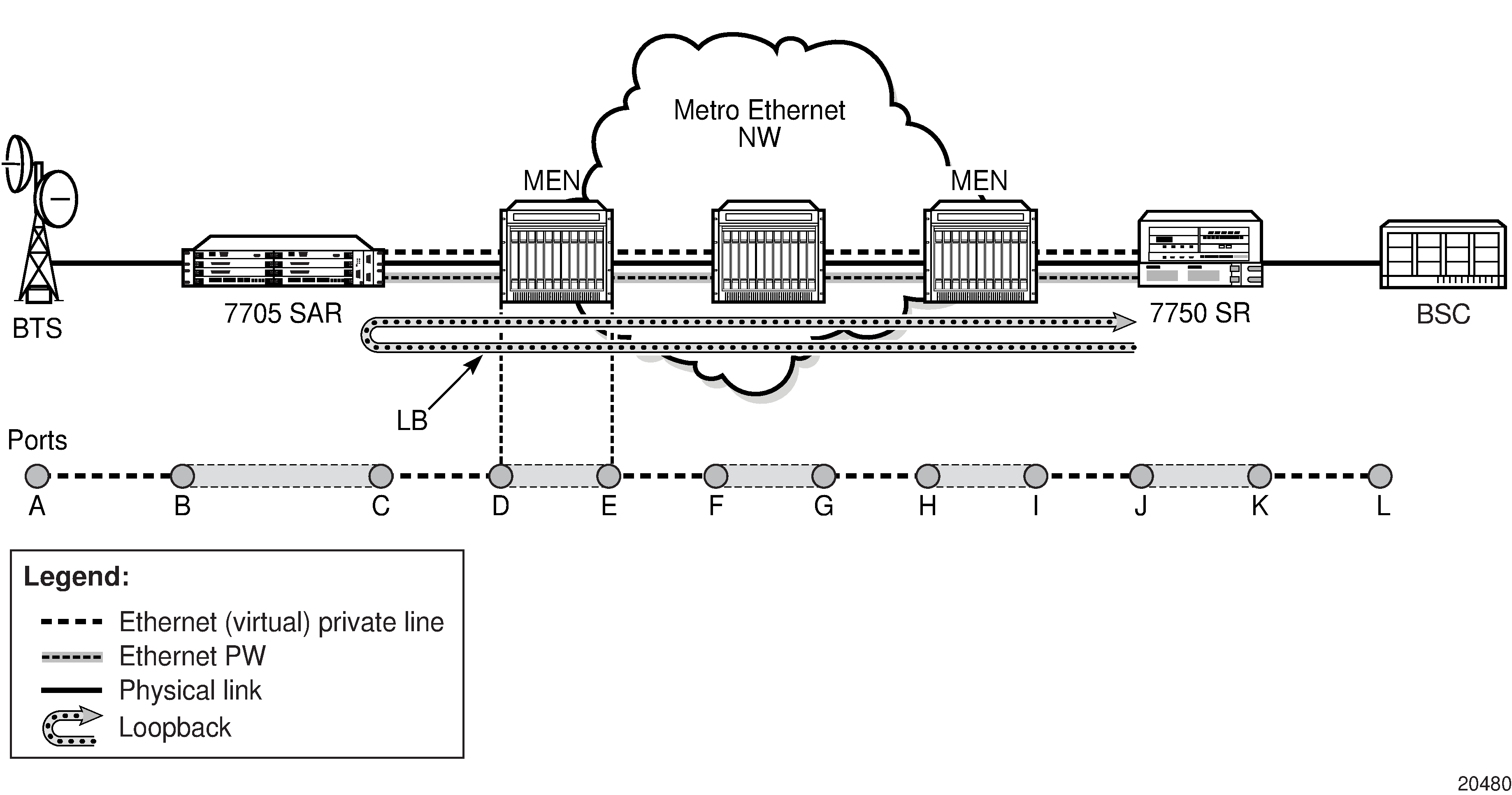
Linktrace (ETH-LT)
The linktrace function is supported by 802.1ag and Y.1731 on the 7705 SAR. A Linktrace Message (LTM) is originated by a MEP and targeted to a peer MEP in the same MA and within the same MD level. Its function is similar to IP traceroute. The peer MEP responds with a Linktrace Reply (LTR) message after successful inspection of the LTM.
ETH-LT tests are run using the oam>eth-cfm>linktrace command.
Throughput Measurement
Throughput measurement is performed by sending frames to the far end at an increasing rate (up to wire speed) and measuring the percentage of frames received back. In general, the rate is dependent on frame size; the larger the frame size, the lower the rate.
The Y.1731 specification recommends the use of unicast ETH-LB and ETH-Test frames to measure throughput.
On the 7705 SAR, LBM processing and LBR generation is enhanced and occurs on the datapath, allowing the node to respond to loopback messages at wire speed and making in-service throughput tests possible. Therefore, if the 7705 SAR receives LBMs at up to wire speed, it can generate up to an equal number of LBRs. In order to process LBMs at wire speed, there must be either no TLVs or a single TLV (which is a data TLV) in the LBM frame. The End TLV field (0) must be present and the frame can be padded with data after the End TLV field in order to increase the size of the frame. The MAC address cannot be a multicast MAC address; it must be the MEP MAC destination address (DA).
Datapath processing of LBMs is supported with dot1ag and Y.1731 for the following MEPs:
SAP Up and Down MEPs
spoke SDP Up and Down MEPs
mesh SDP Up and Down MEPs (VPLS only)
For spoke or mesh SDP Up and Down MEPs, fastpath (datapath) LBM processing requires that both interfaces—the LBM receiver and the LBR transmitter—reside on the same adapter card. For example, if the 7705 SAR must perform a reroute operation and needs to move the next hop interface to another adapter card (that is, LBMs are received on one card and LBRs are transmitted on another), the fastpath processing of LBMs is terminated and LBM processing continues via the CSM.
Continuity Check (ETH-CC)
The continuity check function is supported by 802.1ag and Y.1731 on the 7705 SAR. A Continuity Check Message (CCM) is a multicast frame that is generated by a MEP and sent to its remote MEPs in the same MA. The CCM does not require a reply message. To identify faults, the receiving MEP maintains a MEP database with the MAC addresses of the remote MEPs with which it expects to maintain connectivity checking. The MEP database can be provisioned manually. If there is no CCM from a monitored remote MEP in a preconfigured period, the local MEP raises an alarm.
Continuity checks are enabled using the eth-cfm>mep>ccm-enable command for Epipe and VPLS services and for router network interfaces.
The following CC capabilities are supported:
enable and disable CC for a MEP
automatically put local MEPs into the database when they are created
manually configure and delete the MEP entries in the CC MEP monitoring database. The only local provisioning required to identify a remote MEP is the remote MEP identifier (using the remote-mepid mep-id command).
CCM transmit interval: 10ms, 100ms, 1s, 10s, 1m, 10m (default: 10s)
transmit interval: 10ms, 100ms, 1s, 10s, 1m, 10m (default: 10s)
CCM declares a fault when it:
stops hearing from one of the remote MEPs for a period of 3.5 times the CC interval
hears from a MEP with a lower MD level
hears from a MEP that is not in the same MA
hears from a MEP that is in the same MA but is not in the configured MEP list
hears from a MEP that is in the same MA with the same MEP ID as the receiving MEP
recognizes that the CC interval of the remote MEP does not match the local configured CC interval
recognizes that the remote MEP declares a fault
An alarm is raised and a trap is sent if the defect is greater than or equal to the configured low-priority-defect value.
CC must be enabled in order for RDI information to be carried in the CCM OAMPDU
The optional ccm-tlv-ignore command can be used to ignore the receipt of interface-status and port-status TLVs in the ETH-CCM PDU on a facility MEP. No processing is performed on ignored ETH-CCM TLV values.
Any TLV that is ignored is reported as absent to the relevant remote peer, and the values in the TLV do not have any effect. This is the same behavior as if the received ETH-CCM PDU never included these TLVs in the first place. If the TLV is not properly formed, the ETH-CCM PDU will fail the packet parsing process, which will cause it to be discarded and an alarm to be raised.
Remote Defect Indication (ETH-RDI)
The Ethernet Remote Defect Indication function (ETH-RDI) is used by a MEP to communicate to its peer MEPs that a defect condition has been encountered. Defect conditions such as signal failure and AIS may result in the transmission of frames with ETH-RDI information. ETH-RDI is used only when ETH-CC transmission is enabled and it is enabled automatically.
ETH-RDI has the following two applications:
single-ended fault management — the receiving MEP detects an RDI defect condition, which gets correlated with other defect conditions in this MEP. The absence of received ETH-RDI information in a single MEP indicates the absence of defects in the entire MEG.
contribution to far-end performance monitoring — the transmitting MEP reflects that there was a defect at the far end, which is used as an input to the performance monitoring process
A MEP that is in a defect condition transmits frames with ETH-RDI information. A MEP, upon receiving frames with ETH-RDI information, determines that its peer MEP has encountered a defect condition.
The specific configuration information required by a MEP to support the ETH-RDI function is as follows:
MEG level — the MEG level at which the MEP exists
ETH-RDI transmission period — application-dependent and is the same value as the ETH-CC transmission period
priority — the priority of frames containing ETH-RDI information and is the same value as the ETH-CC priority
The PDU used to carry ETH-RDI information is the CCM.
-
if the hold-mep-up-on-failure command is enabled:
-
the Up MEP indicates ETH-RDI
-
the remote MEP indicates a DefMACstatus
-
-
if the hold-mep-up-on-failure command is disabled:
-
the Up MEP indicates a DefRemoteCCM defect
-
the remote MEP indicates both a DefMACstatus and a DefRDICCM defect
-
The hold-mep-up-on-failure command is not supported for VPLS SAPs.
Alarm Indication Signal (ETH-AIS)
The Ethernet Alarm Indication Signal function (ETH-AIS) is a Y.1731 CFM enhancement used to suppress alarms at the client (sub) layer following detection of defect conditions at the server (sub) layer.
Transmission of frames with ETH-AIS information can be enabled or disabled on a Y.1731 SAP MEP.
ETH-AIS is enabled using the eth-cfm>mep>ais-enable command for Epipe and VPLS services.
Frames with ETH-AIS information can be issued at the client MEG level by a MEP, including a server MEP, upon detecting the following conditions:
signal failure conditions in the case where ETH-CC is enabled
AIS condition in the case where ETH-CC is disabled
For a point-to-point Ethernet connection at the client (sub) layer, a client layer MEP can determine that the server (sub) layer entity providing connectivity to its peer MEP has encountered a defect condition upon receiving a frame with ETH-AIS information. Alarm suppression is simplified by the fact that a MEP is expected to suppress only those defect conditions associated with its peer MEP.
Only a MEP, including a server MEP, is configured to issue frames with ETH-AIS information. Upon detecting a defect condition, the MEP can immediately start transmitting periodic frames with ETH-AIS information at a configured client MEG level. A MEP continues to transmit periodic frames with ETH-AIS information until the defect condition is removed. Upon receiving a frame with ETH-AIS information from its server (sub) layer, a client (sub) layer MEP detects the AIS condition and suppresses alarms associated with all its peer MEPs. After the AIS condition is cleared, a MEP resumes alarm generation upon detecting defect conditions.
The following specific configuration information is required by a SAP MEP to support ETH-AIS:
client MEG level — the MEG level at which the most immediate client layer MEPs exist
ETH-AIS transmission period — the transmission period of frames with ETH-AIS information
priority — the priority of frames with ETH-AIS information
Test Error (ETH-Test)
The Ethernet Test (signal) function (ETH-Test) is a Y.1731 CFM enhancement used to perform one-way, on-demand, in-service diagnostics tests, which include verifying frame loss and bit errors. ETH-Test is supported on Y.1731 SAP MEPs and facility MEPs on network interfaces.
ETH-Test is enabled using the eth-cfm>mep>eth-test-enable command for Epipe and VPLS services and for router network interfaces and is run using the oam>eth-cfm>eth-test command.
When configured to perform such tests, a MEP inserts frames with ETH-Test information such as frame size and transmission patterns.
When an in-service ETH-Test function is performed, data traffic is not disrupted and the frames with ETH-Test information are transmitted.
To support ETH-Test, a Y.1731 SAP or facility MEP requires the following configuration information:
MEG level — the MEG level at which the MEP exists
unicast MAC address — the unicast MAC address of the peer MEP for which the ETH-Test is intended
data — an optional element with which to configure data length and contents for the MEP. The contents can be a test pattern and an optional checksum.
Examples of test patterns include all 0s or all 1s. At the transmitting MEP, this configuration information is required for a test signal generator that is associated with the MEP. At the receiving MEP, this configuration is required for a test signal detector that is associated with the MEP.
priority — the priority of frames with ETH-Test information
A MEP inserts frames with ETH-Test information toward a targeted peer MEP. The receiving MEP detects the frames with ETH-Test information and performs the requested measurements.
ITU-T Y.1731 Performance Monitoring (PM)
The Y.1731 Performance Monitoring (PM) functions can be used to measure Ethernet frame delay, delay variation, throughput (including throughput at queue-rates), and frame loss. These performance parameters are defined for point-to-point Ethernet connections.
Frame Delay and Delay Variation Measurements (ETH-DM and ETH-DV)
The Y.1731 recommendation covers the following performance parameters, which are based on Metro Ethernet Forum (MEF) 10:
frame delay — specified as one-way or round-trip delay for a frame, where frame delay is defined as the time elapsed since the start of transmission of the first bit of the frame by a source node until the reception of the frame by the destination node or the same source node
frame delay variation — a measure of the variations in the frame delay between a pair of service frames, where the service frames belong to the same CoS instance on a point-to-point Ethernet connection
The performance parameters listed above are applicable to Ethernet services frames. Services frames are those frames that conform to an agreed-upon level of bandwidth profile conformance and are associated with a particular CoS identifier. Services frames are admitted at the ingress Ethernet flow point of a point-to-point Ethernet connection and should be delivered to the egress Ethernet flow point.
The 7705 SAR supports one-way and two-way Ethernet Delay Measurement (ETH-DM) tests (section 8.2 of the Y.1731 standard). The tests are run using the oam>eth-cfm>one-way-delay-test and oam>eth-cfm>two-way-delay-test commands. Ethernet Delay Variation (ETH-DV) tests are run concurrently with the one-way and two-way ETH-DM tests.
For ETH-DM, the accuracy of the measurement is in the microseconds range.
Y.1731 Delay Measurement (DM)
Y.1731 delay measurement implementation ensures the most accurate results under all circumstances. The implementation ensures that there is minimal delay measurement error between packet generation and packet play-out over the Ethernet link.
In order to isolate delay measurement results from the effects of any queuing, scheduling, and shaping procedures, timestamping of source one-way and two-way delay measurement (1DM and DMM) frames in the transmit direction occurs when the first byte of the DM frame is put on the wire (that is, once the actual serialization starts). Last-minute timestamping ensures that DM tests truly measure the delay between two SAP, spoke SDP, mesh SDP, or port endpoints, and not the delay imposed by the routers. Using these accurate measurements, a network operator can separate the delay introduced by the routers from the transmission delay introduced by the transmission network, such as a Metro Ethernet network (MEN) or Generic Framing Procedure (GFP) over SONET links.
Timestamping of received 1DM and DMM frames is similar to transmitted source 1DM and DMM frames. When a Y.1731 delay measurement frame is identified internally, it is immediately timestamped to ensure reporting of only the network-induced delay and jitter.
With two-way delay measurement, delay measurement reply (DMR) timestamping occurs at the entry point to the egress datapath. DMR frames are then classified according to their configured dot1p setting and experience any scheduling delays experienced by the queue and scheduling priorities that the frames are associated with. Performing DMR timestamping at the entry point to the egress datapath provides the most accurate end-to-end measurement of delay and jitter, as it takes into account the internal delay of the responding node due to other higher-priority packets.
In summary, one-way delay measurement performs timestamping in the transmit direction only when the frame is about to be sent on the wire and in the receive direction when the frame is received, before any queuing at the far end. This provides true transport network-induced delay and jitter measurements. Two-way delay measurement takes into account the delay introduced by queuing and scheduling of the far-end node for true end-to-end measurements.
Frame Loss Measurement (ETH-LM)
The 7705 SAR supports single-ended and dual-ended Ethernet Loss Measurement (ETH-LM) tests. Single-ended LM tests are run using the oam>eth-cfm>single-ended-loss-test command and are considered on-demand tests. Dual-ended LM tests are enabled using the eth-cfm>mep>dual-ended-loss-test-enable command for Epipe services and network router interfaces. When enabled, dual-ended LM tests run continuously in the background.
Y.1731 loss measurement functionality is implemented to ensure the most accurate results under all circumstances. Each adapter card has a network processor (NP). LM counters are maintained at the NP. The NP is responsible for incrementing and resetting these counters. These counters are accessed by the CSM CPU in order to calculate and display the loss (percentage) to the user.
LM/CCM frames follow the associated QoS path and therefore might inadvertently report loss due to local congestion even before the frame is switched onto the link. In order to reflect the true experience of a particular QoS setting, generated LM/CCM frames follow the egress QoS path. Once generated, these frames are classified in the same manner as the applicable dot1p-to-FC mapping, associated queuing, and scheduling rules. Following the proper path ensures that loss measurements reflect the experience of a given FC all the way through the network, including within the 7705 SAR platform. As is the case for any other frame of the same FC (that is, user or control frame), the LM/CCM frame follows the associated QoS path to reflect the real experience.
For example, newly generated LM/CCM frames that have a higher counter value can be forwarded sooner than LM/CCM frames with a lower counter value that have been generated but are waiting to be serviced (that is, frames with a lower queue, a queue in the out-of-profile state; or a single SAP with multiple FCs). As a result, when under congestion, the LM ratio would increase to reflect local loss if lower-priority frames cannot be serviced in a timely manner.
In addition, congestion, and hence prioritization, can occur anywhere in the transport network, which means that a reordering could take place not only on the ingress point, but anywhere in the network along the entire path.
The loss ratio is calculated based on the aggregate frames being transmitted and received. In an uncongested network, the loss ratio would be 0%. With congestion, not all frames may be sent out to the network (that is, higher priority traffic, and so on) or any one of the transit nodes or the endpoint node might drop the packet, which would end up with loss.
The above-described behavior for following the QoS path equally applies to both Up and Down MEPs. Loss measurements in both up and down directions for the same MEP can be performed simultaneously.
The counters used for loss measurement in LM and CCM frames are appended as late as possible in the datapath. Appending the counters at the last minute to the LM or CCM frames ensures that a scheduling priority issue or some other queue-delaying event does not delay the OAM frame in a queue. If the counters are updated or generated earlier in the datapath, then the OAM frames could be affected by queuing or scheduling delays, which could cause the frames to be counted as lost frames when the far-end receive timer expires.
The following notes apply to Y.1731 LM tests.
Single-ended and dual-ended LM tests cannot be enabled on a MEP simultaneously. That is, either a single-ended or a dual-ended LM test can be enabled on a specific MEP at any one time.
The behavior and the interaction between single- and dual-ended LM tests are described in the following list. Error conditions, such as correct domain level and valid destination address (DA) MAC, are not covered in the list:
if dual-ended LM test is disabled:
CCM frames are transmitted with LM counters set to 0
CCM frames being received are not processed for LM
LMM and LMR frames being received are processed
single-ended tests can be enabled (not blocked by CLI)
if dual-ended LM test is enabled:
single-ended tests cannot be enabled (blocked by CLI)
LMM and LMR frames being received will be dropped
Multiple MEPs bound to the same Epipe SAP but belonging to different MEG levels can perform LM tests simultaneously.
CCM must be enabled before a dual-ended LM test can be enabled.
When a dual-ended LM test is enabled, the user cannot disable CCM. The dual-ended LM test needs to be disabled before the CCM can be disabled.
For dual-ended LM tests, an alarm is declared when frame losses are greater than an alarm threshold configured for the MEP. The granularity of the alarm threshold (declaring or clearing) is 0.01%. The default threshold is set to 0.25%.
On a per-SAP or per-network interface basis, there is one set of Rx and Tx Local LM counters and one set of Rx and Tx Remote LM counters. LM counters are not separated on a per-MAC source address (SA) basis. All MEPs, regardless of their MD or MEG level, share the same set of Rx and Tx LM counters.
On the CLI, there are interval counters and accumulated counters. The CCM counters are referred to as Local and FarEnd counters and the accumulated counters are referred to as Near-End and Far-End counters.
The LM counters are incremented when a user data frame reaches a SAP. Because there is only one set of Tx and Rx Local counters per SAP, each user data frame received by all the MEPs configured on that SAP is counted.
OAM frames with MEP levels matching or lower than the locally configured MEP level are not counted. They are treated and processed as OAM frames. This functionality applies to both received and transmitted OAM frames. CFM OAM frames at higher MEP levels are counted as user data frames.
For example, assume a SAP with two MEPs configured on it; one MEP at level 5 and the other at level 6.
When a level 6 OAM frame is received, it is extracted to the CSM for processing and is not counted by LM counters. It is treated as an OAM frame.
The same behavior applies in the transmit direction. In the above example, any level 5 or level 6 OAM frames generated by the local SAR would not be counted by the far-end LM counters.
For dual-ended LM tests, any received CCMs with all LM counters being 0s (zeros) are treated as invalid. In this case, the 7705 SAR resets the LM counters for the current and previous CCMs to 0s (zeros). Accumulated counters are not reset.
Except for a valid counter rollover scenario, if the value of any CCM/LMR counter is less than the value of the same counter in the previous CCM/LMR frame, then the accumulated values of all counters are not increased; they are kept at the same values as before the last CCM/LMR frame is processed.
When the first valid CCM/LMR frame — that is, a frame with at least one non-zero LM counter — is received after a dual-ended loss test is enabled or a single-ended loss test is launched, the accumulated values cannot be calculated. In this case, the counters are resaved as current counters. When the next received CCM/LMR frame with valid LM counts is received, it will trigger the update of accumulated counts.
Accumulated counts always start at 0 for each launch of a single-ended test. However, the accumulated counts do not change nor do they get reset to all 0s when dual-ended loss tests become disabled. For dual-ended loss tests, accumulated counts can be restarted at 0 by removing the existing LM result of a particular MEP with the CLI command clear>eth-cfm>dual-ended-loss-test>mep mep-id domain md-index association ma-index, or the equivalent SNMP command.
ITU-T Y.1731 Ethernet Bandwidth Notification (ETH-BN)
The Ethernet Bandwidth Notification (ETH-BN) function, as defined in ITU-T Rec. G.8013/Y.1731, is used by a server MEP to signal changes in link bandwidth to a client MEP.
One of the best applications of this functionality is for point-to-point microwave radios. When a microwave radio uses adaptive modulation, the capacity of the radio can change based on the condition of the microwave link. For example, in adverse weather conditions that cause link degradation, the radio can change its modulation scheme to a more robust one (which will reduce the link bandwidth) in order to continue transmitting.
This change in bandwidth is communicated from the server MEP on the radio, using ETH-BNM (Ethernet Bandwidth Notification Message), to the client MEP on the connected router. The router responds to this information by adjusting the rate of traffic being sent to the radio. The server MEP continues to transmit periodic frames with ETH-BN information with the currently available bandwidth. When full bandwidth is restored, the ETH-BNM will start indicating the full bandwidth.
When the 7705 SAR is interoperating with 9500 MPR-e radios, ETH-BN functionality is supported with 9500 MPR-e radios in standalone mode or in MWA mode.
The 7705 SAR supports the client side of ETH-BN, receiving and acting on the ETH-BN information sent by the server MEP.
ETH-BN is supported on Ethernet ports on the following adapter cards, modules, and platforms:
8-port Gigabit Ethernet Adapter card
10-port 1GigE/1-port 10GigE X-Adapter card
Packet Microwave Adapter card
6-port Ethernet 10Gbps Adapter card
2-port 10GigE (Ethernet) Adapter card (v-port)
2-port 10GigE (Ethernet) module (v-port)
6-port SAR-M Ethernet module
all fixed platforms, with the exception of Fast Ethernet ports on the 7705 SAR-A (ports 9 to 12)
The ports can be configured for network, access, or hybrid mode. When ETH-BN is enabled on a port with the egress-rate sub-rate allow-eth-bn-rate-changes command, the egress rate, which was configured as a fixed bandwidth, can be dynamically changed based on the available bandwidth indicated by the ETH-BN server.
The maximum egress rate that the port can be set to is the native port rate (for example, 1 Gb/s), and the minimum egress rate is 1 kb/s. If a rate request is outside that range, including 0, it cannot be implemented, and the egress rate is set as close as possible to the requested rate. Any request for a change less than 1% is ignored.
To reduce the number of bandwidth changes (each change incurs a small data hit), a hold timer can be configured. The range is 1 to 600 s with a default of 5 s. Any ETH-BN message received before the hold timer expires, after the last bandwidth change, is ignored.
The bandwidth indicated by the ETH-BN server includes the FCS; therefore, the include-fcs option must also be selected in the egress-rate command or the bandwidth will not match the intended rate.
For information on the egress-rate command, refer to the ‟Ethernet Commands” section in the 7705 SAR Interface Configuration Guide, ‟Configuration Command Reference” chapter.
Bandwidth Notification Message (BNM)
The PDU used for ETH-BN information is called the Bandwidth Notification Message (BNM).
The BNM PDU format consists of the following fields:
MEG level – carries the MEG level of the client MEP (0 to 7); this field can be any value
Version – current version is 0
OpCode – value for this PDU type is GMN (32)
Flags – contains one information element:
period – bits 3 to 1 indicate how often BN messages are transmitted; currently, the only valid values are 100 (1 frame/s), 101 (1 frame/10 s), and 110 (1 frame/min)
TLV Offset – set to 13
Sub-OpCode – value for this PDU type is BNM (1)
Nominal Bandwidth – the nominal full bandwidth of the link, in Mb/s; this information is ignored by the 7705 SAR
Current Bandwidth – the current bandwidth of the link, in Mb/s
Port ID – a non-zero unique identifier for the port associated with the ETH-BN information, or zero if not used; this information is ignored by the 7705 SAR
End TLV – all zeros octet value
Typical behavior for ETH-BN is that if no BNM frames are received within an interval of 3.5 times the BNM transmission period indicated in the last BNM frame received, the MEP signals to the management system that it no longer has any bandwidth information (for example, because the full bandwidth has been restored). For the 7705 SAR implementation, no action is taken if no BNM frame arrives within 3.5 periods.
Upon startup or restart of the system, the configured egress rate is used until a BNM arrives on the port with a new bandwidth request from the ETH-BN server MEP.
Event logs are generated each time the egress bandwidth is changed based on reception of a BNM. If a BNM is received that does not result in a bandwidth change, no event log is generated.
BN messages are transmitted with a source MAC address that cannot be a multicast address or have a value of 0. The destination MAC address can be a Class 1 multicast address (that is, 01-80-C2-00-0x) or the MAC address of the configured port. If these conditions are not satisfied, the message is discarded. The packets are rate-limited to the CSM as are all OAM packets.
BN messages with zero, one, or two VLAN tags are supported.
CFM OAM QoS
It is important that CFM OAM tools use the relevant FC and the associated queue to report traffic performance issues such as delay, jitter, and loss. When user traffic is mapped to one FC/queue and the OAM traffic is mapped to another FC/queue, data reported by the OAM tools might not be a true reflection of the performance metrics that the user traffic is experiencing, due mainly to different queue depths and scheduling priorities.
In order to ensure that CFM OAM traffic experiences the same treatment as user traffic, the 7705 SAR supports a configurable priority to specify the FC, and therefore the queue, to be used for a specified OAM test. The priority keyword in the eth-cfm loopback, one-way-delay-test, single-ended-loss-test, two-way-delay-test and two-way-slm-test commands is used to configure the FC mapping as per the configured priority. The priority value maps to a specific FC; therefore, selecting a priority selects the FC. Y.1731 Priority-to-FC Mapping lists the priority-to-FC mapping. This mapping of priority to FC cannot be changed by the user.
Priority |
FC-ID |
FC Name |
|---|---|---|
0 |
0 |
BE |
1 |
1 |
L2 |
2 |
2 |
AF |
3 |
3 |
L1 |
4 |
4 |
H2 |
5 |
5 |
EF |
6 |
6 |
H1 |
7 |
7 |
NC |
The priority-to-FC mapping does change depending on the message type and direction of the MEP. Priority Mapping Based on Message Type and MEP Direction summarizes the FC and Dot1p priority mappings based on this criteria.
MEP type |
Message type |
FC |
Dot1p |
|---|---|---|---|
SAP Down MEP |
CCM |
Dictated via ccm-ltm-priority value |
Dictated via ccm-ltm-priority value |
LMM, DMM, 1DM, LBM |
User-defined priority value copied |
User-defined priority value copied |
|
LMR, DMR, LBR |
ccm-ltm-priority value |
Incoming dot1p priority preserved |
|
SAP Up MEP |
CCM |
User-defined priority value copied to dot1p and FC as per sap-ingress classification |
Dictated via ccm-ltm-priority value |
LMM, DMM, 1DM, LBM |
User-defined priority value copied to dot1p and FC as per sap-ingress classification |
User-defined priority value copied |
|
LMR, DMR, LBR |
User-defined priority value copied to dot1p and FC as per sap-ingress classification |
Incoming dot1p priority preserved |
For more information, see the 7705 SAR Services Guide, "Priority Mapping (802.1ag and Y.1731)".
EFM OAM (802.3ah)
802.3ah Clause 57 defines the Ethernet in the First Mile (EFM) OAM sublayer, which is a link-level Ethernet OAM that is supported on 7705 SAR Ethernet ports configured as network or access ports. It provides mechanisms for monitoring link operations such as remote fault indication and remote loopback control. Ethernet OAM gives network operators the ability to monitor the health of Ethernet links and quickly determine the location of failing CFM links or fault conditions.
Because some of the sites where the 7705 SAR will be deployed will have only Ethernet uplinks, this OAM functionality is mandatory. For example, mobile operators must be able to request remote loopbacks from the peer router at the Ethernet layer in order to debug any connectivity issues. EFM OAM provides this capability.
EFM OAM defines a set of events that may impact link operation. The following critical link events (defined in 802.3ah clause 57.2.10.1) are supported:
-
link fault: the PHY has determined that a fault has occurred in the receive direction of the local DTE
-
dying gasp: an unrecoverable local failure condition has occurred
-
critical event: an unspecified critical event has occurred
These critical link events are signaled to the remote DTE by the flag field in OAMPDUs.
EFM OAM is supported on network and access Ethernet ports, and is configured at the Ethernet port level. The access ports can be configured to tunnel the OAM traffic originated by the far-end devices.
EFM OAM has the following characteristics.
All EFM OAM, including loopbacks, operate on point-to-point links only.
EFM loopbacks are always line loopbacks (line Rx to line Tx).
When a port is in loopback, all frames (except EFM frames) are discarded. If dynamic signaling and routing is used (dynamic LSPs, OSPF, IS-IS, or BGP routing), all services also go down. If all signaling and routing protocols are static (static routes, LSPs, and service labels), the frames are discarded but services stay up.
The following EFM OAM functions are supported:
OAM capability discovery
configurable transmit interval with an Information OAMPDU
active or passive mode
OAM loopback
OAMPDU tunneling and termination (for Epipe service)
dying gasp at network and access ports
For information about Epipe service, see the 7705 SAR Services Guide, "Ethernet VLL (Epipe) Services".
Unidirectional OAM Operation
Some physical layer devices support unidirectional OAM operation. When a link is operating in unidirectional OAM mode, the OAM sublayer ensures that only information OAMPDUs with the Link Fault critical link event indication set and no Information TLVs are sent across the link.
Remote Loopback
EFM OAM provides a link-layer frame loopback mode, which can be controlled remotely.
To initiate a remote loopback, the local EFM OAM client enables the OAM remote loopback command to send a loopback control OAMPDU. After receiving the loopback control OAMPDU, the remote OAM client puts the remote port into local loopback mode.
OAMPDUs are slow protocol frames that contain appropriate control and status information used to monitor, test, and troubleshoot OAM-enabled links.
To exit a remote loopback, the local EFM OAM client sends a loopback control OAMPDU by disabling the OAM remote loopback command. After receiving the loopback control OAMPDU, the remote OAM client puts the port back into normal forwarding mode.
When a port is in local loopback mode (the far end requested an Ethernet OAM loopback), any packets received on the port will be looped back, except for EFM OAMPDUs. No data will be transmitted from the node; only data that is received on the node will be sent back out.
When the node is in remote loopback mode, local data from the CSM is transmitted, but any data received on the node is dropped, except for EFM OAMPDUs.
Remote loopbacks should be used with caution; if dynamic signaling and routing protocols are used, all services go down when a remote loopback is initiated. If only static signaling and routing is used, the services stay up. On the 7705 SAR, the Ethernet port can be configured to accept or reject the remote-loopback command.
802.3ah OAMPDU Tunneling and Termination for Epipe Services
Customers who subscribe to Epipe service might have customer equipment running 802.3ah at both ends. The 7705 SAR can be configured to tunnel EFM OAMPDUs received from a customer device to the other end through the existing network using MPLS or GRE, or to terminate received OAMPDUs at a network or an access Ethernet port.
While tunneling offers the ability to terminate and process the OAM messages at the head-end, termination on the first access port at the cell site can be used to detect immediate failures or can be used to detect port failures in a timelier manner.
The user can choose either tunneling or termination, but not both at the same time.
In EFM OAM (Dot3ah) Capabilities on the 7705 SAR, scenario 1 shows the termination of received EFM OAMPDUs from a customer device on an access port, while scenario 2 shows the same thing except for a network port. Scenario 3 shows tunneling of EFM OAMPDUs through the associated Ethernet PW. To configure termination (scenario 1), use the config>port>ethernet>efm-oam>no shutdown command.
Dying Gasp
Dying gasp is used to notify the far end that EFM-OAM is disabled or shut down on the local port. The dying gasp flag is set on the OAMPDUs that are sent to the peer. The far end can then take immediate action and inform upper layers that EFM-OAM is down on the port.
When a dying gasp is received from a peer, the node logs the event and generates an SNMP trap to notify the operator.
Ethernet Loopbacks
The following loopbacks are supported on Ethernet ports:
timed network line loopback
timed and untimed access line loopbacks
timed and untimed access internal loopbacks
persistent access line loopback
persistent access internal loopback
MAC address swapping
CFM loopback on network and access ports
CFM loopback on ring ports and v-port
Line and Internal Ethernet Loopbacks
A line loopback loops frames received on the corresponding port back toward the transmit direction. Line loopbacks are supported on ports configured for access or network mode.
Similarly, a line loopback with MAC addressing loops frames received on the corresponding port back toward the transmit direction, and swaps the source and destination MAC addresses before transmission. See MAC Swapping for more information.
An internal loopback loops frames from the local router back to the framer. This is usually referred to as an equipment loopback. The transmit signal is looped back and received by the interface. Internal loopbacks are supported on ports configured in access mode.
If a loopback is enabled on a port, the port mode cannot be changed until the loopback has been disabled.
A port can support only one loopback at a time. If a loopback exists on a port, it must be disabled or the timer must expire before another loopback can be configured on the same port. EFM-OAM cannot be enabled on a port that has an Ethernet loopback enabled on it. Similarly, an Ethernet loopback cannot be enabled on a port that has EFM-OAM enabled on it.
When an internal loopback is enabled on an Ethernet port, autonegotiation is turned off silently. This is to allow an internal loopback when the operational status of a port is down. Any user modification to autonegotiation on a port configured with an internal Ethernet loopback will not take effect until the loopback is disabled.
The loopback timer can be configured from 30 s to 86400 s. All non-zero timed loopbacks are turned off automatically under the following conditions: an adapter card reset, activity switch, or timer expiry. Line or internal loopback timers can also be configured as a latched loopback by setting the timer to 0 s, or as a persistent loopback with the persistent keyword. Latched and persistent loopbacks are enabled indefinitely until turned off by the user. Latched loopbacks survive adapter card resets and activity switches, but are lost if there is a system restart. Persistent loopbacks survive adapter card resets and activity switches and can survive a system restart if the admin>save or admin>save>detail command was executed before the restart. Latched loopbacks (untimed) and persistent loopbacks can be enabled only on Ethernet access ports.
Persistent loopbacks are the only Ethernet loopbacks saved to the database by the admin>save and admin>save>detail commands.
MAC Swapping
Typically, an Ethernet port loopback only echoes back received frames. That is, the received source and destination MAC addresses are not swapped. However, not all Ethernet equipment supports echo mode, where the original sender of the frame must support receiving its own port MAC address as the destination MAC address.
The MAC swapping feature on the 7705 SAR is an optional feature that swaps the received destination MAC address with the source MAC address when an Ethernet port is in loopback mode. After the swap, the FCS is recalculated to ensure the validity of the Ethernet frame and to ensure that the frame is not dropped by the original sender because of a CRC error.
Interaction of Ethernet Port Loopback with Other Features
EFM OAM and line loopback are mutually exclusive. If one of these functions is enabled, it must be disabled before the other can be used.
However, a line loopback precedes the dot1x behavior. That is, if the port is already dot1x-authenticated it will remain so. If it is not, EAP authentication will fail.
Ethernet port-layer line loopback and Ethernet port-layer internal loopback can be enabled on the same port with the down-when-looped feature. EFM OAM cannot be enabled on the same port with the down-when-looped feature. For more information,see the 7705 SAR Interface Configuration Guide, "Ethernet Port Down-When-Looped".
CFM Loopbacks for OAM on Ethernet Ports
Connectivity fault management (CFM) loopback support for loopback messages (LBMs) on Ethernet ports allows operators to run standards-based Layer 1 and Layer 2 OAM tests on ports receiving unlabeled packets.
The 7705 SAR supports CFM MEPs associated with different endpoints (that is, Up and Down SAP MEPs, Up and Down spoke SDP MEPs, Up and Down mesh SDP MEPs, and network interface facility Down MEPs). In addition, for traffic received from an uplink (network ingress), the 7705 SAR supports CFM LBM for both labeled and unlabeled packets. CFM loopbacks are applied to the Ethernet port.
See Ethernet OAM Capabilities for information about CFM MEPs.
CFM Loopback on Ethernet Ports shows an application where an operator leases facilities from a transport network provider in order to transport traffic from a cell site to their MTSO. The operator leases a certain amount of bandwidth between the two endpoints (the cell site and the MTSO) from the transport provider, who offers Ethernet Virtual Private Line (EVPL) or Ethernet Private Line (EPL) PTP service.
Before the operator offers services on the leased bandwidth, the operator runs OAM tests to verify the SLA. Typically, the transport provider (MEN provider) requires that the OAM tests be run in the direction of (toward) the first Ethernet port that is connected to the transport network. This is done in order to eliminate the potential effect of queuing, delay, and jitter that may be introduced by an SDP or SAP.
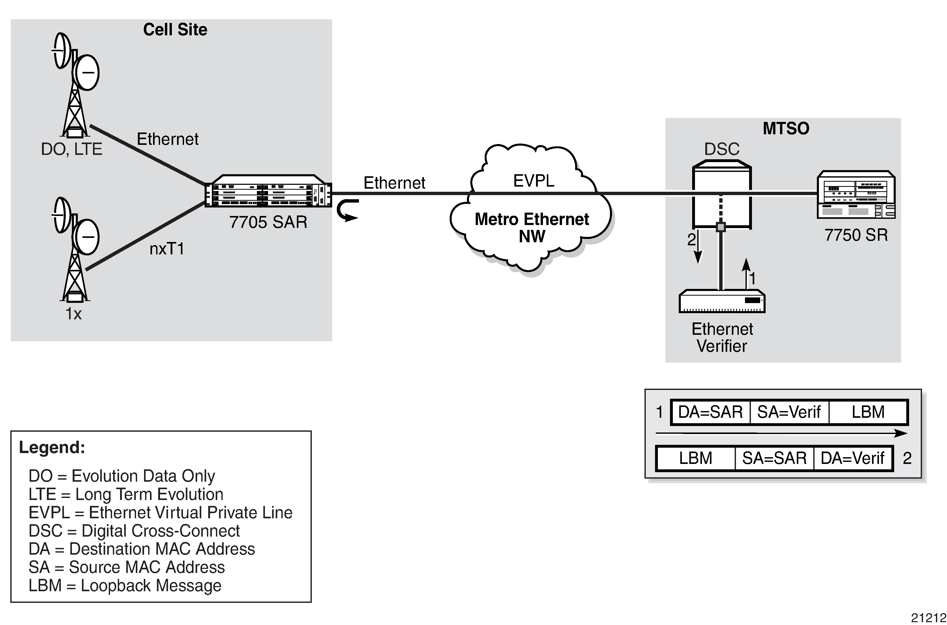
CFM Loopback on Ethernet Ports shows an Ethernet verifier at the MTSO that is directly connected to the transport network (in front of the 7750 SR). Therefore, the Ethernet OAM frames are not label- encapsulated. Because Ethernet verifiers do not support label operations and the transport provider mandates that OAM tests be run between the two hand-off Ethernet ports, the verifier cannot be relocated behind the 7750 SR node at the MTSO. Therefore, CFM loopback frames received are not MPLS-encapsulated, but are simple Ethernet frames where the type is set to CFM (dot1ag or Y.1731).
CFM Loopback Mechanics
The following list contains important facts to consider when working with CFM loopbacks:
CFM loopbacks can be enabled on a per-port basis, and:
the port can be in access or network mode
when enabled on a port, all received LBM frames are processed, regardless of the VLAN and the service that the VLAN or SAP is bound to
there is no associated MEP creation involved with this feature; therefore, no domain, association, or similar checks are performed on the received frame
upon finding a destination address MAC match, the LBM frame is sent to the CFM process
CFM loopback support on a physical ring port on the 2-port 10GigE (Ethernet) Adapter card/module differs from other Ethernet ports. For these ports, cfm-loopback is configured, optionally, using dot1p and match-vlan to create a list of up to 16 VLANs. The null VLAN is always applied. The CFM loopback message will be processed if it does not contain a VLAN header, or if it contains a VLAN header with a VLAN ID that matches one in the configured match-vlan list.
received LBM frames undergo no queuing or scheduling in the ingress direction
at egress, loopback reply (LBR) frames are stored in their own queue; that is, a separate new queue is added exclusively for LBR frames
users can configure the way a response frame is treated among other user traffic stored in network queues; the configuration options are high priority, low priority, or dot1p, where dot1p applies only to physical ring ports
for network egress or access egress, where 4-priority scheduling is enabled:
high priority: either cir = port_speed, which applies to all frames that are scheduled via an expedited in-profile scheduler, or RR for all other (network egress queue) frames that reside in expedited queues and are in an in-profile state
low priority: either cir = 0, pir = port_speed, which applies to all frames that are scheduled via a best effort out-of-profile scheduler, or RR for all other frames that reside in best-effort queues and are in an out-of-profile state
for the 8-port Gigabit Ethernet Adapter card, 10-port 1GigE/1-port 10GigE X-Adapter card, and the v-port on the 2-port 10GigE (Ethernet) Adapter card/module, for network egress, where 16-priority scheduling is enabled:
high priority: has higher priority than any user frames
low priority: has lower priority than any user frames
for the physical ring ports on the 2-port 10GigE (Ethernet) Adapter card/module, which can only operate as network egress, the priority of the LBR frame is derived from the dot1p setting of the received LBM frame. Based on the assigned ring-type network queue policy, dot1p-to-queue mapping is handled using the same mapping rule that applies to all other user frames.
the above queue parameters and scheduler mappings are all preconfigured and cannot be altered. The required QoS treatment is selected by enabling the CFM loopback and specifying high-priority, low-priority, or dot1p.
OAM Propagation to Attachment Circuits
Typically, T1/E1 equipment at a site relies on the physical availability of the T1/E1 ports to determine the uplink capacity (that is, for ATM IMA or MLPPP groups). When a failure in the access link between the 7705 SAR and the associated T1/E1 equipment is detected, notification of the failure is propagated by the PW status signaling using one of two methods — label withdrawal or TLV (see LDP Status Signaling). In addition, the PW failure must also be propagated to the devices attached to the T1/E1 equipment. The propagation method depends on the type of port used by the access circuit (ATM, T1/E1 TDM, or Ethernet) and is described below.
ATM Ports
Propagation of ATM PW failures to the ATM port is achieved through the generation of AIS and RDI alarms.
T1/E1 TDM Ports
If a port on a 16-port T1/E1 ASAP Adapter card, 32-port T1/E1 ASAP Adapter card, or 2-port OC3/STM1 Channelized Adapter card is configured for CESoPSN VLL service, failure of the VLL forces a failure of the associated DS0s (timeslots). Because there can be n ✕ DS0s bound to a CESoPSN VLL service as the attachment circuit, an alarm is propagated to the bound DS0s only. In order to emulate the failure, an "all 1s" or an "all 0s" signal is sent through the DS0s. The bit pattern can be configured to be either all 1s or all 0s. This is sometimes called "trunk conditioning".
Ethernet Ports
For an Ethernet port-based Ethernet VLL, failure of the VLL forces a failure of the local Ethernet port. That is, the local attachment port is taken out of service at the physical layer and the Tx is turned off on the associated Ethernet port.
Pseudowire Status Signaling OAM Propagation
See the 7705 SAR Services Guide for more information about frame relay and HDLC PW status signaling and OAM propagation.
LDP Status Signaling
The failure of a local circuit needs to be propagated to the far-end PE, which then propagates the failure to its attached circuits. The 7705 SAR can propagate failures over the PW using one of the following methods:
LDP status via label withdrawal
LDP status via TLV
LDP Status via Label Withdrawal
Label withdrawal is negotiated during the PW status negotiation phase and needs to be supported by both the near-end and the far-end points. If the far end does not support label withdrawal, the 7705 SAR still withdraws the label in case the local attachment circuit is removed or shut down.
Label withdrawal occurs only when the attachment circuit is administratively shut down or deleted. If there is a failure of the attached circuit, the label withdrawal message is not generated.
When the local circuit is re-enabled after shutdown, the VLL must be re-established, which causes some delays and signaling overhead.
LDP Status via TLV
Signaling PW status via TLV is supported as per RFC 4447. Signaling PW status via TLV is advertised during the PW capabilities negotiation phase. It is more efficient and is preferred over the label withdrawal method.
For cell mode ATM PWs, when an AIS message is received from the local attachment circuit, the AIS message is propagated to the far-end PE unaltered and PW status TLV is not initiated.
IP Multicast Debugging Tools
This section describes multicast debugging tools for the 7705 SAR.
The debugging tools for multicast consist of three elements, which are accessed from the CLI <global> level:
Mtrace
Assessing problems in the distribution of IP multicast traffic can be difficult. The multicast traceroute (mtrace) feature uses a tracing feature implemented in multicast routers that is accessed via an extension to the IGMP protocol. The mtrace feature is used to print the path from the source to a receiver; it does this by passing a trace query hop-by-hop along the reverse path from the receiver to the source. At each hop, information such as the hop address, routing error conditions, and packet statistics are gathered and returned to the requester.
Data added by each hop includes:
query arrival time
incoming interface
outgoing interface
previous hop router address
input packet count
output packet count
total packets for this source/group
routing protocol
TTL threshold
forwarding/error code
The information enables the network administrator to determine:
the flow of the multicast stream
where multicast flows stop
When the trace response packet reaches the first-hop router (the router that is directly connected to the source's network interface), that router sends the completed response to the response destination (receiver) address specified in the trace query.
If a multicast router along the path does not implement the mtrace feature or if there is an outage, no response is returned. To solve this problem, the trace query includes a maximum hop count field to limit the number of hops traced before the response is returned. This allows a partial path to be traced.
The reports inserted by each router contain not only the address of the hop, but also the TTL required to forward the packets and flags to indicate routing errors, plus counts of the total number of packets on the incoming and outgoing interfaces and those forwarded for the specified group. Examining the differences in these counts for two separate traces and comparing the output packet counts from one hop with the input packet counts of the next hop allows the calculation of packet rate and packet loss statistics for each hop to isolate congestion problems.
Finding the Last-Hop Router
The trace query must be sent to the multicast router that is the last hop on the path from the source to the receiver. If the receiver is on the local subnet (as determined by the subnet mask), then the default method is to send the trace query to all-routers.mcast.net (224.0.0.2) with a TTL of 1. Otherwise, the trace query is sent to the group address since the last-hop router will be a member of that group if the receiver is. Therefore, it is necessary to specify a group that the intended receiver has joined. This multicast query is sent with a default TTL of 64, which may not be sufficient for all cases.
When tracing from a multihomed host or router, the default receiver address may not be the required interface for the path from the source. In that case, the required interface should be specified explicitly as the receiver.
Directing the Response
By default, mtrace first attempts to trace the full reverse path, unless the number of hops to trace is explicitly set with the hop option. If there is no response within a 3-s timeout interval, a "*" is displayed and the probing switches to hop-by-hop mode. Trace queries are issued starting with a maximum hop count of one and increasing by one until the full path is traced or no response is received. At each hop, multiple probes are sent. The first attempt is made with the unicast address of the host running mtrace as the destination for the response. Because the unicast route may be blocked, the remainder of attempts request that the response be sent to mtrace.mcast.net (224.0.1.32) with the TTL set to 32 more than what is needed to pass the thresholds seen so far along the path to the receiver. For the last attempts, the TTL is increased by another 32.
Alternatively, the TTL may be set explicitly with the TTL option.
For each attempt, if no response is received within the timeout, a "*" is displayed. After the specified number of attempts have failed, mtrace will try to query the next-hop router with a DVMRP_ASK_NEIGHBORS2 request (as used by the mrinfo feature) to determine the router type.
The output of mtrace is a short listing of the hops in the order they are queried, that is, in the reverse of the order from the source to the receiver. For each hop, a line is displayed showing:
the hop number (counted negatively to indicate that this is the reverse path)
the multicast routing protocol
the threshold required to forward data (to the previous hop in the listing as indicated by the up-arrow character)
the cumulative delay for the query to reach that hop (valid only if the clocks are synchronized)
The response ends with a line showing the round-trip time which measures the interval from when the query is issued until the response is received, both derived from the local system clock.
Mtrace/mstat packets use special IGMP packets with IGMP type codes of 0x1E and 0x1F.
Mstat
The mstat feature adds the capability to show the multicast path in a limited graphic display and indicates drops, duplicates, TTLs, and delays at each node. This information is useful to the network operator because it identifies nodes with high drop and duplicate counts. Duplicate counts are shown as negative drops.
The output of mstat provides a limited pictorial view of the path in the forward direction with data flow indicated by arrows pointing downward and the query path indicated by arrows pointing upward. For each hop, both the entry and exit addresses of the router are shown if different, along with the initial TTL required on the packet in order to be forwarded at this hop and the propagation delay across the hop assuming that the routers at both ends have synchronized clocks. The output consists of two columns, one for the overall multicast packet rate that does not contain lost/sent packets and the other for the (S,G)-specific case. The (S,G) statistics also do not contain lost/sent packets.
Mrinfo
The mrinfo feature is a simple mechanism to display the configuration information from the target multicast router. The type of information displayed includes the multicast capabilities of the router, code version, metrics, TTL thresholds, protocols, and status. This information can be used by network operators, for example, to verify if bidirectional adjacencies exist. When the specified multicast router responds, the configuration is displayed.
Microwave Awareness Performance Monitoring Statistics
A 7705 SAR-8 Shelf V2 or 7705 SAR-18 equipped with a Packet Microwave Adapter card provides the capability to collect the following Microwave Awareness (MWA) performance monitoring statistics for microwave radios:
Performance monitoring can be enabled using the config>port>mw>radio> perfmon command. See the 7705 SAR Interface Configuration Guide, "Microwave Link Commands".
G.826 Statistics
G.826 statistics include 15-min. and 24-hr performance statistics of a radio's microwave link. These statistics include Background Block Errors (BBE), Errored Seconds (ES), Severely Errored Seconds (SES), and Unavailable Seconds (UAS) as specified in ITU-T Recommendation G.826.
Radio Power Level Statistics
Power level statistics include 15-min. and 24-hr performance statistics of a radio's received and transmit minimum, average, and maximum levels for over the period. The statistics are collected in units of A-weighted decibels (dBA).
Adaptive Coding and Modulation Statistics
The radios can automatically adjust their mode of operation based on the atmospheric conditions. A radio's adaptive coding and modulation (ACM) function use its highest modulation (256 QAM) in ideal conditions to attain the highest bandwidth possible and automatically brings down the level of modulation (and therefore bandwidth over the air) as needed in inferior atmospheric conditions.
The collected ACM statistics include 15-min. and 24-hr statistics of the time spent at each QAM level for a radio. The statistics are collected in units of milliseconds.
Service Assurance Agent Overview
Broadband service delivery technologies have enabled the introduction of broadband service termination applications such as Voice over IP (VoIP), TV service delivery, and video and high-speed Internet services. These new applications force carriers to produce services where the health and quality of Service Level Agreement (SLA) commitments are verifiable, both to the customer and internally (within the carrier).
SAA is a feature that monitors network operations using statistics for parameters such as latency, jitter, response time, and packet loss. The information can be used to troubleshoot network problems and help in problem prevention and network topology planning. The 7705 SAR also supports the following SAA Ethernet CFM tests: loopback, linktrace, two-way delay measurement, and two-way SLM.
The results are saved in SNMP tables that are queried by either the CLI or a management system. Threshold monitors allow for both rising and falling threshold events to alert the provider if SLA performance statistics deviate from the required parameters. SAA CFM tests can be saved to accounting files that can be accessed by the network management system.
SAA allows two-way timing for several applications. This provides carriers and their customers with data to verify that the SLA agreements are being properly enforced. For SAA ICMP ping, one-way timestamping can be enabled at the system level for all outbound SAA ICMP ping packets.
Traceroute Implementation
For various applications, such as LSP traceroute, packets must pass through the network processor while on their way to the control CPU. When the packets exit the control CPU in the egress direction, the network processor inserts a timestamp inside each packet. Only packets processed by the control CPU will receive a timestamp.
When interpreting these timestamps, care must be taken because some nodes are not capable of providing timestamps, as such timestamps must be associated with the same IP address that is being returned to the originator to indicate which hop is being measured.
SAA Jitter
Mobile operators require millisecond granularity for delay and jitter measurements. This is especially true for synchronization-over-packet based applications.
Two-way jitter tests measure the jitter in each direction separately. The 7705 SAR provides two-way jitter tests with millisecond granularity for all network deployment applications.
SAA Ethernet CFM Test Support
CFM loopback, linktrace, and two-way delay measurement tests (ETH-DM) can be initiated using SAA. Additional timestamping is required for loopback and linktrace tests. An organization-specific TLV is used on both sender and receiver nodes to carry the timestamp information. Currently, timestamps are only applied by the sender node. This means that any time measurements resulting from the loopback and linktrace tests include the packet processing time used by the remote node. Because ETH-DM uses a four timestamp approach to remove the remote processing time, it should be used for accurate delay measurements.
The SAA versions of the CFM loopback, linktrace, and ETH-DM tests support send-count, interval, timeout, and FC. The summary of the test results are stored in an SAA accounting file.
The 7705 SAR supports SAA-triggered ETH-DM tests for both Y.1731 and 802.1ag MEPs for Ethernet SAPs (Epipe and VPLS) and facility MEPs on network interfaces.
Writing SAA Ethernet CFM Test Results to Accounting Files
When each SAA CFM test is completed, the 7705 SAR collects the results in an accounting file that can be accessed by the network management system. In order to write the SAA test results to an accounting file in a compressed XML format, the results must be collected and entered in the appropriate MIB table, and a record must be generated in the appropriate accounting file. After an accounting file has been created, accounting information can be specified and collected under the config>log>acct-policy>to file log-file-id context. See the 7705 SAR System Management Guide, "Configuring an Accounting Policy" section for information about creating accounting files and writing to them.
Configuring SAA Test Parameters
Use the following CLI syntax to create an SAA test and set test parameters:
- CLI Syntax:
config# saaconfig>saa# test pingconfig>saa>test$ typeconfig>saa>test>type$ icmp-ping 10.10.221.131 count 50 fc ‟nc” profile outconfig>saa>test>type$ exitconfig>saa>test# no shutdownconfig>saa>test# exitconfig>saa# exit
The following example displays the SAA test configuration output:
A:ALU-48>config>saa
----------------------------------------------
        test "ping"
            type
                icmp-ping 10.10.221.131 count 50 fc ‟nc” profile out
            exit
            no shutdown
        exit
----------------------------------------------
The following example displays the result after running the test:
A:ALU-48>config>saa# show saa ping
===============================================================================
SAA Test Information
===============================================================================
Test name                    : ping
Owner name                   : TiMOS CLI
Description                  : N/A
Accounting policy            : None
Administrative status        : Enabled
Test type                    : icmp-ping 10.10.221.131 count 50 fc "nc"
                               profile out
Trap generation              : None
Test runs since last clear   : 1
Number of failed test runs   : 0
Last test result             : Success
-------------------------------------------------------------------------------
Threshold
Type        Direction Threshold  Value      Last Event          Run #
-------------------------------------------------------------------------------
Jitter-in   Rising    None       None       Never               None
            Falling   None       None       Never               None
Jitter-out  Rising    None       None       Never               None
            Falling   None       None       Never               None
Jitter-rt   Rising    None       None       Never               None
            Falling   None       None       Never               None
Latency-in  Rising    None       None       Never               None
            Falling   None       None       Never               None
Latency-out Rising    None       None       Never               None
            Falling   None       None       Never               None
Latency-rt  Rising    None       None       Never               None
            Falling   None       None       Never               None
Loss-in     Rising    None       None       Never               None
            Falling   None       None       Never               None
Loss-out    Rising    None       None       Never               None
            Falling   None       None       Never               None
Loss-rt     Rising    None       None       Never               None
            Falling   None       None       Never               None

===============================================================================
Test Run: 1
Total number of attempts: 50
Number of requests that failed to be sent out: 0
Number of responses that were received: 50
Number of requests that did not receive any response: 0
Total number of failures: 0, Percentage: 0
 (in ms)            Min          Max      Average       Jitter
Outbound  :        -9.61        -8.75        -9.18        0.016
Inbound   :         9.53         12.0         10.2        0.412
Roundtrip :        0.674         2.59         1.02        0.406

Per test packet:
  Sequence     Outbound      Inbound    RoundTrip Result
         1        -8.75         9.53        0.784 Response Received
         2        -8.76         9.54        0.779 Response Received
         3        -8.78         9.59        0.805 Response Received
         4        -8.79         11.3         2.46 Response Received
         5        -8.82         9.61        0.786 Response Received
         6        -8.83         9.59        0.760 Response Received
         7        -8.86         9.65        0.795 Response Received
         8        -8.86         9.63        0.767 Response Received
         9        -8.89         9.68        0.797 Response Received
        10        -8.90         9.68        0.775 Response Received
        11        -8.93         9.73        0.805 Response Received
        12        -8.93         10.4         1.44 Response Received
        13        -8.97         9.75        0.788 Response Received
        14        -8.98         11.2         2.23 Response Received
        15        -9.00         9.80        0.801 Response Received
        16        -9.01         9.79        0.787 Response Received
        17        -9.03         9.82        0.794 Response Received
        18        -9.04         10.9         1.89 Response Received
        19        -9.06         9.87        0.801 Response Received
        20        -9.08         9.85        0.770 Response Received
        21        -9.10         9.90        0.804 Response Received
        22        -9.11         9.90        0.782 Response Received
        23        -9.14         9.97        0.828 Response Received
        24        -9.15         9.93        0.780 Response Received
        25        -9.17         9.99        0.813 Response Received
        26        -9.18         9.97        0.786 Response Received
        27        -9.21         10.5         1.28 Response Received
        28        -9.22         11.0         1.79 Response Received
        29        -9.25         10.1        0.807 Response Received
        30        -9.26         10.0        0.767 Response Received
        31        -9.28         10.1        0.804 Response Received
        32        -9.29         9.96        0.676 Response Received
        33        -9.31         10.0        0.719 Response Received
        34        -9.32         10.1        0.785 Response Received
        35        -9.35         10.2        0.808 Response Received
        36        -9.36         10.1        0.782 Response Received
        37        -9.39         11.3         1.87 Response Received
        38        -9.40         12.0         2.59 Response Received
        39        -9.43         10.2        0.792 Response Received
        40        -9.43         10.2        0.771 Response Received
        41        -9.46         10.3        0.815 Response Received
        42        -9.46         10.1        0.674 Response Received
        43        -9.49         12.0         2.46 Response Received
        44        -9.50         10.3        0.782 Response Received
        45        -9.53         10.3        0.810 Response Received
        46        -9.54         10.3        0.780 Response Received
        47        -9.57         10.3        0.768 Response Received
        48        -9.58         10.3        0.769 Response Received
        49        -9.60         10.4        0.797 Response Received
        50        -9.61         11.2         1.60 Response Received
===============================================================================
*A:ALU-48#
Synthetic Loss Measurement (SLM)
SLM is a single-ended test that can be run on demand or proactively to determine in-loss, out-loss, and unacknowledged packets. The test uses a small amount of synthetic test traffic as a substitute for customer traffic. SLM is used between peer MEPs in point-to-point configurations. Only remote peer MEPs within the association and matching the unicast destination will respond to the SLM packet. SLM uses an optional TLV with a timestamp on the near-end and far-end MEPs for the combined loss and delay measurement.
Various sequence numbers and counters are used to determine loss in each direction. In order to properly use the information that is gathered, the following terms are defined:
count — number of probes that are sent if the last frame is not lost. If the last frame is lost, the count plus the number of unacknowledged packets equals the number of probes sent.
out-loss (far end) — packets lost on the way to the remote node from the test initiator
in-loss (near end) — packets lost on the way back from the remote node to the test initiator
unacknowledged — number of packets not responded to by the end of the test
An SLM test packet can be generated using the CLI or SNMP for an on-demand test and SAA for a proactive test. The on-demand test provides per-probe-specific loss indicators or individual probe information stored in the MIB. The test does not store data for later processing. An SAA scheduled or continuous test summarizes the per-probe data but does not maintain per-probe information, and any unacknowledged packets are recorded as in-loss packets.
SLM packets originate and terminate on the CSM card. The probe count for SLM has a configurable range of 1 to 100 with probe spacing between 1 s and 10 s. A single test therefore can be up to 1000 s in length. A node may only initiate and maintain a single active on-demand test at any given time. The results table maintains a maximum of one storage entry per remote MEP. Subsequent tests on the same peer overwrite the results for that peer. For this reason, operators should run the on-demand test and check the results before starting another test.
Proactive measurement functions are linked to SAA and provide scheduling, storage, and summarization capabilities. Scheduling can be continuous or periodic. Proactive measurement also allows for the interpretation and representation of data that may enhance the specification. As an example, an optional TLV allows for the measurement of both loss and delay/ jitter with a single test. The optional TLV is ignored by equipment that does not support it. In mixed-vendor environments, loss measurement is tracked but delay and jitter only report round-trip times.
The round-trip times in mixed-vendor environments include the remote node's processing time because only two timestamps are included in the packet. In an environment where both nodes support the optional TLV to include timestamps, unidirectional and round-trip times are reported. Because all four timestamps are included in the packet, the round-trip time in this case does not include remote node processing time.
The ETH-SL packet format contains a test-id that is internally generated and not configurable. The display summary for the on-demand test shows the test-id. A remote node processing the SLM frames could receive overlapping test-ids as a result of multiple MEPs measuring the loss at the same remote MEP. For this reason, the uniqueness of the test is based on the remote MEP-ID, test-id, and source MAC address of the packet.
All Ethernet adapter cards and ports in access mode support SLM Up and Down MEPs, and all Ethernet adapter cards and ports in network mode that support spoke or mesh SDPs support SLM Up and Down MEPs. SLM Down MEPs are also supported on Ethernet network interfaces. There is no coordination between various fault conditions that could impact loss measurement. This is also true for conditions where MEPs are placed in a shutdown state as a result of linkage to a redundancy scheme such as MC-LAG.
It is possible to have a valid configuration where multiple MEPs on the same remote node have the same MAC address. If this is the case, the first responder is used to measure packet loss. The second responder is dropped.
A configurable inactivity timer determines the length of time that an on-demand test is valid. The test is active as long as packets are received within the timeframe set by the inactivity timer, as defined by the test-id, remote MEP ID, and source MAC address. If there is a gap between the packets that exceeds the inactivity timer value, the responding node responds with a sequence number of 1. For the remote MEP, the previous test has expired and any new probes are now part of a new test. The inactivity timer default is 100 s with a range of 10 to 100 s.
The responding node is limited to 1000 concurrent SLM tests. A node that is already actively processing 1000 SLM tests will show as out-loss or unacknowledged packets on the node that initiated the test because the packets will be silently discarded at the responder. No log entries or alarms will be raised. These packets are ETH-CFM-based and the stated receive rate for ETH-CFM must not be exceeded for the platform.
Only the configuration is supported by the high availability function. There is no synchronization of data between active and standby. Any unwritten or active tests are lost during a switchover and the data cannot be recovered.
Configuration Example
SLM Example shows the configuration required for a proactive SLM test using SAA.
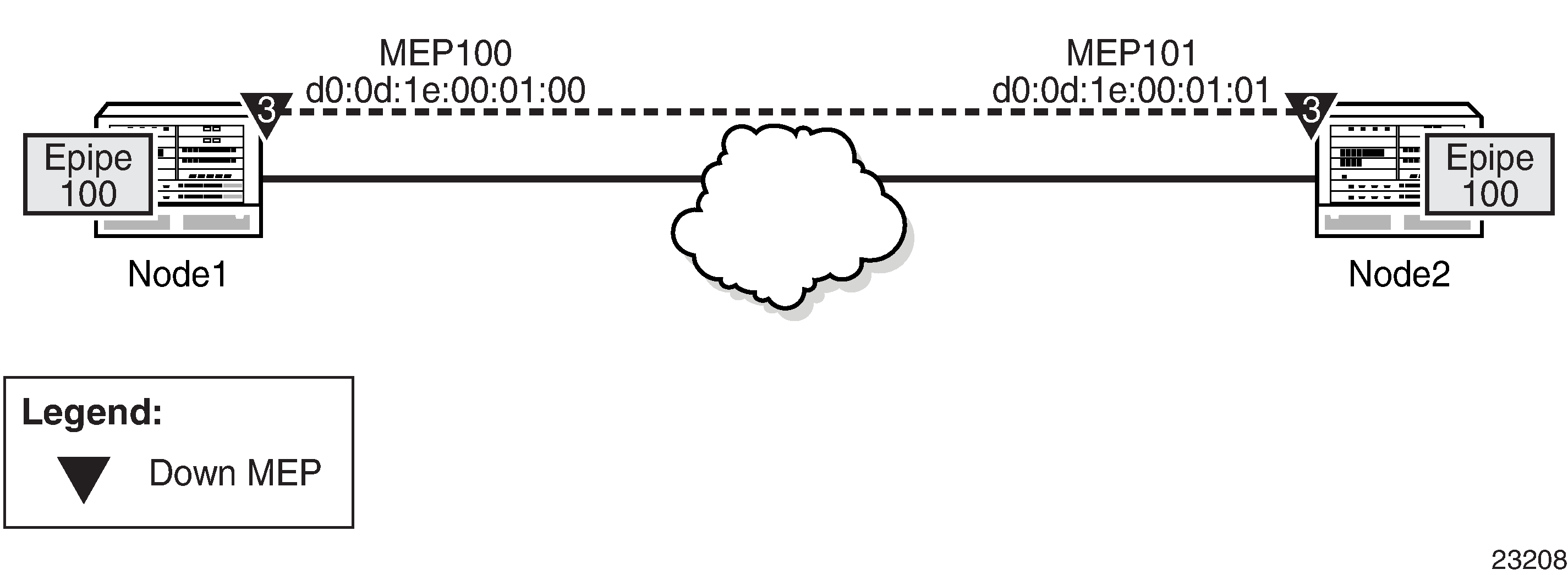
Node1 is tested for this example. The SAA configuration does not include the accounting policy required to collect the statistics before they are overwritten. Node2 does not have an SAA configuration. Node2 includes the configuration to build the MEP in the Epipe service context.
The following example displays the Node1 SAA test configuration:
Node1>config>eth-cfm# info
----------------------------------------------
            domain 3 format none level 3
                association 1 format icc-based name ‟03-0000000100”
                    bridge-identifier 100
                    exit
                    ccm-interval 1
                    remote-mepid 101
            exit
        exit
----------------------------------------------
Node1>config>service>epipe# info
----------------------------------------------
            sap 1/3/1:100 create
                eth-cfm
                    mep 100 domain 3 association 1 direction down
                        ccm-enable
                        no shutdown
                    exit
                exit
            exit
            spoke-sdp 131:100 create
            exit
            no shutdown
----------------------------------------------
Node1>config>saa# info
----------------------------------------------
          test ‟slml”
            type
                eth-cfm-two-way-slm d0:0d:1e:00:01:01 mep 100 domain 3
 association 1 count 100 timeout 1 interval 1
            exit
            continuous
            no shutdown
       exit
----------------------------------------------
The following example displays the Node2 configuration:
Node2>config>eth-cfm# info
----------------------------------------------
            domain 3 format none level 3
                association 1 format icc-based name ‟03-0000000100”
                    bridge-identifier 100
                    exit
                    ccm-interval 1
                    remote-mepid 100
                exit
            exit
----------------------------------------------
Node2>config>service>epipe# info
----------------------------------------------
            sap 1/3/1:100 create
                eth-cfm
                    mep 101 domain 3 association 1 direction down
                        ccm-enable
                        no shutdown
                    exit
                exit
            exit
            spoke-sdp 131:100 create
            exit
            no shutdown
----------------------------------------------
The following output example shows the different loss conditions that an operator may see. The total number of attempts is ‛99” because the final probe in the test was not acknowledged.
# show saa slm1
Test Run: 183
Total number of attempts: 99
Number of requests that failed to be sent out: 0
Number of responses that were received: 48
Number of requests that did not receive any response: 50
Total number of failures: 50, Percentage: 50
(in ms)      Min  Max  Average  Jitter
Outbound :  -370 -362  -366     0.432
Inbound :    363  371   367     0.308
Roundtrip : 0.000 5.93  1.38    0.496
Per test packet:
Sequence Outbound  Inbound    RoundTrip  Result
1         0.000    0.000       0.000     Out Loss
2         0.000    0.000       0.000     Out Loss
3         0.000    0.000       0.000     Out Loss
4         0.000    0.000       0.000     Out Loss
…snip…
46       -369       370      1.28      Response Received
47       -362       363      1.42      Response Received
48       0.000     0.000     0.000     In Loss
49       0.000     0.000     0.000     In Loss
50      -362       363       1.42      Response Received
51      -362       363       1.16      Response Received
52      -362       364       1.20      Response Received
53      -362       364       1.18      Response Received
54      -363       364       1.20      Response Received
…snip…
96      -369      370        1.29      Response Received
97      -369      370        1.30      Response Received
98     0.000      0.000      0.000     Unacknowledged
99     0.000      0.000      0.000     Unacknowledged
100    0.000      0.000      0.000     Unacknowledged
The following is an example of an on-demand test and the associated output. Only single test runs are stored and can be viewed after the fact.
#oam eth-cfm two-way-slm-test d0:0d:1e:00:01:01 mep 100 domain 3 association 1 send-
count 20 interval 1 timeout 1
Sending 20 packets to d0:0d:1e:00:01:01 from MEP 100/3/1 (Test-id: 588)
Sent 20 packets, 20 packets received from MEP ID 101, (Test-id: 588)
(0 out-loss, 0 in-loss, 0 unacknowledged)
# show eth-cfm mep 100 domain 3 association 1 two-way-slm-test
===============================================================================
Eth CFM Two-way SLM Test Result Table (Test-id: 588)
===============================================================================
Peer Mac Addr    Remote MEP   Count   In Loss   Out Loss   Unack
-------------------------------------------------------------------------------
d0:0d:1e:00:01:01  101          20       0        0          0
OAM timestamping
The following tables provide information about OAM timestamping for OAM tests.
Location of OAM timestamping lists the locations where each type of OAM timestamping can occur.
Timestamping type |
Timestamp location |
|
|---|---|---|
Tx |
Rx |
|
A |
At the edge after enqueue |
At the edge before enqueue |
B |
Before enqueuing |
At the edge before enqueue |
C |
CSM timestamping |
|
Mapping of OAM tests to timestamping lists the mapping of OAM tests to timestamping.
Test execution |
Test |
OAM type |
MEP and direction |
Timestamping type |
|---|---|---|---|---|
SAA |
eth-cfm |
Loopback |
SAP Down MEP |
A |
SAA |
eth-cfm |
Loopback |
SAP Up MEP |
A |
SAA |
eth-cfm |
Loopback |
Spoke SDP and Mesh SDP Down MEP |
A |
SAA |
eth-cfm |
Loopback |
Spoke SDP and Mesh SDP Up MEP |
A |
SAA |
eth-cfm |
Loopback |
Network interface Down MEP |
A |
SAA |
eth-cfm |
Linktrace |
SAP Down MEP |
A |
SAA |
eth-cfm |
Linktrace |
SAP Up MEP |
A |
SAA |
eth-cfm |
Linktrace |
Spoke SDP and Mesh SDP Down MEP |
A |
SAA |
eth-cfm |
Linktrace |
Spoke SDP and Mesh SDP Up MEP |
A |
SAA |
eth-cfm |
Linktrace |
Network interface Down MEP |
A |
SAA |
eth-cfm |
SLM |
SAP Down MEP |
A |
SAA |
eth-cfm |
SLM |
SAP Up MEP |
A |
SAA |
eth-cfm |
SLM |
Spoke SDP and Mesh SDP Down MEP |
A |
SAA |
eth-cfm |
SLM |
Spoke SDP and Mesh SDP Up MEP |
A |
SAA |
eth-cfm |
SLM |
Network interface Down MEP |
A |
SAA |
eth-cfm |
DM |
SAP Down MEP |
A |
SAA |
eth-cfm |
DM |
SAP Up MEP |
B |
SAA |
eth-cfm |
DM |
Spoke/Mesh SDP Down MEP |
A |
SAA |
eth-cfm |
DM |
Spoke/Mesh SDP Up MEP |
B |
SAA |
eth-cfm |
DM |
Network interface Down MEP |
A |
SAA |
lsp-ping |
— |
— |
A |
SAA |
vccv-ping |
— |
— |
A |
SAA |
sdp-ping |
— |
— |
A |
SAA |
vprn-ping |
— |
— |
A |
SAA |
mac-ping |
— |
— |
A |
SAA |
icmp-ping |
— |
— |
C |
SAA |
cpe-ping |
— |
— |
A |
On demand |
eth-cfm |
DM |
SAP Down MEP |
A |
On demand |
eth-cfm |
DM |
SAP Up MEP |
B |
On demand |
eth-cfm |
DM |
Spoke SDP and Mesh SDP Down MEP |
A |
On demand |
eth-cfm |
DM |
Spoke SDP and Mesh SDP Up MEP |
B |
On demand |
eth-cfm |
DM |
Network interface Down MEP |
A |
On demand |
eth-cfm |
1DM |
SAP Down MEP |
B |
On demand |
eth-cfm |
1DM |
SAP Up MEP |
A |
On demand |
eth-cfm |
1DM |
Spoke SDP and Mesh SDP Down MEP |
B |
On demand |
eth-cfm |
1DM |
Spoke SDP and Mesh SDP Up MEP |
A |
On demand |
eth-cfm |
1DM |
Network interface Down MEP |
B |
On demand |
twamp/twamp-light |
— |
Ethernet ports |
A |
On demand |
twamp/twamp-light |
— |
Non-Ethernet ports |
C |
On demand |
lsp-ping |
— |
— |
A |
On demand |
vccv-ping |
— |
— |
A |
On demand |
sdp-ping |
— |
— |
A |
On demand |
vprn-ping |
— |
— |
A |
On demand |
mac-ping |
— |
— |
A |
Timestamps per OAM Test lists the timestamps per OAM test.
| Type | Test | Line card timestamp | Timestamp |
|||
|---|---|---|---|---|---|---|
| T11 | T22 | T33 | T44 | |||
CFM |
loopback |
✓ |
✓ |
— |
— |
✓ |
linktrace |
✓ |
✓ |
— |
— |
✓ |
|
slm |
✓ |
✓ |
✓ |
✓ |
✓ |
|
two-way-delay |
✓ |
✓ |
✓ |
✓ |
✓ |
|
Others |
lsp-ping |
✓ |
✓ |
✓ |
— |
✓ |
vccv-ping |
✓ |
✓ |
✓ |
— |
✓ |
|
sdp-ping |
✓ |
✓ |
✓ |
✓ |
✓ |
|
vprn-ping |
✓ |
✓ |
✓ |
✓ |
✓ |
|
mac-ping |
✓ |
✓ |
✓ |
✓ |
✓ |
|
icmp-ping (with enable icmp-vse) |
✓ |
✓ |
T2 = T3 |
T3 = T2 |
✓ |
|
Notes:
- At the Tx of the initiator or test head
- At the Rx of the responder
- At the Tx of the responder
- At the Rx of the initiator or test head
OAM and SAA Command Reference
Command Hierarchies
Operational Commands
Operational Commands
global
    - ping ip-address | dns-name [rapid | detail] [ttl time-to-live] [tos type-of-service] [size bytes] [pattern pattern] [source ip-address] [interval seconds] [{next-hop ip-address} | {interface interface-name} | [bypass-routing] [count requests] [do-not-fragment] [router router-instance | service-name service-name] [timeout timeout]  [fc fc-name | fc-queue fc-name profile {in | out}]
    - traceroute [ip-address | dns-name] [ttl ttl] [wait milli-seconds] [no-dns] [source ip-address] [tos type-of-service] [router router-instance | service-name service-name]
Multicast Commands
global
    - mrinfo ip-address | dns-name [router router-instance | service-name service-name]
    - mstat source ip-address | dns-name group grp-ip-address | dns-name [destination dst-ip-address | dns-name] [hop hop] [router router-instance | service-name service-name] [wait-time wait-time]
    - mtrace source ip-address | dns-name group grp-ip-address | dns-name [destination dst-ip-address | dns-name] [hop hop] [router router-instance | service-name service-name] [wait-time wait-time]
OAM Commands
ATM Diagnostics
global
    - oam
        - atm-ping {port-id | bundle-id [:vpi | vpi/vci]} [end-to-end | segment] [dest destination-id] [send-count send-count] [timeout timeout] [interval interval]
TWAMP
config
    - test-oam
        - twamp
            - server
                - [no] prefix ip-prefix/mask [create]
                    - description description-string
                    - no description
                    - max-conn-prefix count
                    - no max-conn-prefix
                    - max-sess-prefix count
                    - no max-sess-prefix
                - inactivity-timeout timer
                - no inactivity-timeout
                - max-conn-server count
                - no max-conn-server
                - max-sess-server count
                - no max-sess-server
                - ref-inactivity-timeout timer
                - no ref-inactivity-timeout
                - [no] shutdown
TWAMP Light
For descriptions of Router TWAMP Light commands, see the Router Configuration Guide.
config
    - router
        - twamp-light
            - [no] reflector
                - description description-string
                - [no] prefix ip-prefix/prefix-length [create]
                    - description description-string
                - udp-port number
                - no udp-port
                - [no] shutdown
For descriptions of VPRN TWAMP Light commands, see the Services Guide.
config
    - service
        - vprn
            - twamp-light
                - [no] reflector
                    - description description-string
                    - [no] prefix ip-prefix/prefix-length [create]
                        - description description-string
                    - udp-port number
                    - no udp-port
                    - [no] shutdown
config
    - test-oam
        - twamp
            - twamp-light
                - inactivity-timeout seconds
                - no inactivity-timeout
Global Downstream Mapping Commands
config
    - test-oam
        - mpls-echo-request-downstream-map {dsmap | ddmap}
LSP Diagnostics
global
    - oam
        - lsp-ping lsp-name [path path-name]
        - lsp-ping bgp-label prefix ip-prefix/prefix-length [path-destination ip-address [interface if-name | next-hop ip-address]]
        - lsp-ping prefix ip-prefix/prefix-length [path-destination ip-address [interface if-name | next-hop ip-address]]
        - lsp-ping sr-isis prefix ip-prefix/prefix-length [igp-instance igp-instance] [path-destination ip-address [interface if-name | next-hop ip-address]]
        - lsp-ping sr-ospf prefix ip-prefix/prefix-length [igp-instance igp-instance] [path-destination ip-address [interface if-name | next-hop ip-address]]
        - lsp-ping sr-te lsp-name [path path-name] [path-destination ip-address [interface if-name | next-hop ip-address]]
            - NOTE: options common to all lsp-ping cases:
[fc fc-name [profile {in | out}]] [interval interval] [send-count send-count] [size octets] [src-ip-address ip-address] [timeout timeout] [ttl label-ttl]
        - lsp-trace lsp-name [path path-name]
        - lsp-trace bgp-label prefix ip-prefix/prefix-length [path-destination ip-address [interface if-name | next-hop ip-address]]
        - lsp-trace prefix ip-prefix/prefix-length [path-destination ip-address [interface if-name | next-hop ip-address]]
        - lsp-trace sr-isis prefix ip-prefix/prefix-length [igp-instance igp-instance] [path-destination ip-address [interface if-name | next-hop ip-address]]
        - lsp-trace sr-ospf prefix ip-prefix/prefix-length [igp-instance igp-instance] [path-destination ip-address [interface if-name | next-hop ip-address]]
        - lsp-trace sr-te lsp-name [path path-name] ] [path-destination ip-address [interface if-name | next-hop ip-address]]
            - NOTE: options common to all lsp-trace cases:
[downstream-map-tlv downstream-map-tlv] [fc fc-name [profile {in | out}]] [interval interval] [max-fail no-response-count] [max-ttl max-label-ttl] [min-ttl min-label-ttl] [probe-count probes-per-hop] [size octets] [src-ip-address ip-address] [timeout timeout]
        - p2mp-lsp-ping {ldp p2mp-identifier [sender-addr ip-address] [leaf-addr ip-address[...up to 5 max]]} [fc fc-name [profile {in | out}]] [size octets] [timeout timeout] [detail]
LDP Diagnostics
global
    - oam
        - ldp-treetrace prefix ip-prefix/mask [max-ttl max-label-ttl] [max-path max-paths] [timeout timeout] [retry-count retry-count] [fc fc-name [profile {in | out}]] [downstream-map-tlv {dsmap | ddmap}]
config
    - test-oam
        - [no] ldp-treetrace
            - fc fc-name [profile {in | out}]
            - no fc
            - path-discovery
                - interval minutes
                - no interval
                - max-path max-paths
                - no max-path
                - max-ttl ttl-value
                - no max-ttl
                - policy-statement policy-name [policy-name...(up to 5 max)]
                - no policy-statement
                - retry-count retry-count
                - no retry-count
                - timeout timeout
                - no timeout
            - path-probing
                - interval minutes
                - no interval
                - retry-count retry-count
                - no retry-count
                - timeout timeout
                - no timeout
            - [no] shutdown
SDP Diagnostics
Service Diagnostics
global
    - oam
        - svc-ping ip-address service [service-id] [local-sdp] [remote-sdp]
        - vprn-ping [service-id | service service-name] source ip-address destination ip-address [fc fc-name [profile {in | out}]] [size size] [ttl vc-label-ttl] [count send-count] [return-control] [timeout timeout] [interval interval]
        - vprn-trace [service-id | service service-name] source ip-address destination ip-address [fc fc-name [profile {in | out}]] [size size] [min-ttl vc-label-ttl] [max-ttl vc-label-ttl] [probe-count send-count] [return-control] [timeout timeout] [interval interval]
VLL Diagnostics
global
    - oam
        - vccv-ping sdp-id:vc-id [src-ip-address ip-addr dst-ip-address ip-addr pw-id pw-id] [reply-mode {ip-routed | control-channel}] [fc fc-name [profile {in | out}]] [size octets] [count send-count] [timeout timeout] [interval interval] [ttl vc-label-ttl]
        - vccv-trace sdp-id:vc-id [size octets] [min-ttl min-vc-label-ttl] [max-ttl max-vc-label-ttl] [max-fail no-response-count] [probe-count probe-count] [reply-mode {ip-routed | control-channel}] [timeout timeout-value] [interval interval-value] [fc fc-name [profile {in | out}]] [detail]
Y.1564 Diagnostics
global
    - oam
        - testhead test-name [owner test-owner] testhead-profile profile-id [frame-payload frame-payload-id] sap sap-id [acceptance-criteria acceptance-criteria-id] [color-aware {enable | disable}] [performance-monitoring {enable | disable}]
        - testhead test-name owner test-owner stop
config
    - test-oam
        - testhead-marker-packet-src-mac mac-address
        - testhead-profile profile-id [create]
            - acceptance-criteria acceptance-criteria-id [create]
            - no acceptance-criteria acceptance-criteria-id
                - cir-threshold cir-threshold
                - no cir-threshold
                - jitter-rising-threshold threshold
                - no jitter-rising-threshold
                - jitter-rising-threshold-in in-profile-threshold
                - no jitter-rising-threshold-in
                - jitter-rising-threshold-out out-profile-threshold
                - no jitter-rising-threshold-out
                - latency-rising-threshold threshold
                - no latency-rising-threshold
                - latency-rising-threshold-in in-profile-threshold
                - no latency-rising-threshold-in
                - latency-rising-threshold-out out-profile-threshold
                - no latency-rising-threshold-out
                - loss-rising-threshold threshold
                - no loss-rising-threshold
                - loss-rising-threshold-in in-profile-threshold
                - no loss-rising-threshold-in
                - loss-rising-threshold-out out-profile-threshold
                - no loss-rising-threshold-out
                - pir-threshold pir-threshold
                - no pir-threshold
            - description description-string
            - no description
            - frame-payload payload-id [payload-type [l2 | tcp-ipv4 | udp-ipv4 | ipv4]] [create]
            - no frame-payload payload-id
                - data-pattern hex-string
                - no data-pattern
                - description description-string
                - no description
                - [no] dscp dscp-name
                - dst-ip ipv4 ipv4-address
                - no dst-ip ipv4
                - dst-mac ieee-address
                - no dst-mac
                - dst-port dst-port-number
                - no dst-port
                - ethertype 0x0600..0xffff
                - no ethertype
                - frame-size frame-size
                - no frame-size
                - ip-proto ip-protocol-number
                - no ip-proto
                - ip-tos type-of-service
                - no ip-tos
                - ip-ttl ttl-value
                - no ip-ttl
                - rate rate-in-kbs
                - no rate
                - src-ip ipv4 ipv4-address
                - no src-ip
                - src-mac ieee-address
                - no src-mac
                - src-port src-port-number
                - no src-port
                - vlan-tag-1 vlan-id vlan-id [tpid tpid] [dot1p dot1p-value]
                - no vlan-tag-1
                - vlan-tag-2 vlan-id vlan-id [tpid tpid] [dot1p dot1p-value]
                - no vlan-tag-2
            - rate cir cir-rate-in-kbs [pir pir-rate-in-kbs]
            - no rate
            - [no] test-completion-trap-enable
            - test-duration {[hours hours] [minutes minutes] [seconds seconds]}
            - no test-duration
    - config
        - service
            - [no] epipe service-id [customer customer-id] [vpn vpn-id] [vc-switching]
                - sap sap-id [no-endpoint]
                    - loopback {line | internal} {timer seconds | persistent} [swap-src-dst-mac]
                    - no loopback
VPLS Diagnostics
global
    - oam
        - cpe-ping service service-id destination ip-address [source ip-address] [source-mac ieee-address] [fc fc-name [profile [in | out]] [ttl vc-label-ttl] [count send-count] [send-control] [return-control] [timeout timeout] [interval interval]
        - mac-ping service service-id destination dst-ieee-address [source src-ieee-address] [fc fc-name [profile {in | out}]] [ttl vc-label-ttl] [count send-count] [send-control] [return-control] [interval interval] [timeout timeout]
        - mac-populate service-id mac ieee-address [flood] [age seconds] [force] [target-sap sap-id] [send-control]
        - mac-purge service-id target ieee-address [flood] [send-control] [register] [force]
        - mac-trace service service-id destination ieee-address [source ieee-address] [fc fc-name [profile {in | out}]] [size octets] [min-ttl vc-label-ttl] [max-ttl vc-label-ttl] [probe-count send-count] [send-control] [return-control] [interval interval] [timeout timeout]
Ethernet in the First Mile (EFM) Commands
global
    - oam
        - efm port-id
            - local-loopback {start | stop}
            - remote-loopback {start | stop}
config
    - [no] port {port-id}
        - ethernet
            - efm-oam
                - [no] accept-remote-loopback
                - hold-time time-value
                - no hold-time
                - mode {active | passive}
                - [no] shutdown
                - [no] transmit-interval interval [multiplier multiplier]
                - [no] tunneling
ETH-CFM Commands
global
    - oam
        - eth-cfm
            - eth-test mac-address mep mep-id domain md-index association ma-index [priority priority] [data-length data-length]
            - linktrace mac-address mep mep-id domain md-index association ma-index [ttl ttl-value]
            - loopback mac-address mep mep-id domain md-index association ma-index [send-count send-count] [size data-size] [priority priority]
            - one-way-delay-test mac-address mep mep-id domain md-index association ma-index [priority priority]
            - single-ended-loss-test mac-address mep mep-id domain md-index association ma-index [priority priority] [interval {100ms | 1s}] [send-count send-count]
            - two-way-delay-test mac-address mep mep-id domain md-index association ma-index [priority priority]
            - two-way-slm-test mac-address mep mep-id domain md-index association ma-index [priority priority] [send-count send-count] [size data-size] [timeout timeout] [interval interval]
config
    - eth-cfm
        - domain md-index [format {dns | mac | none | string}] name md-name level level
        - domain md-index
        - no domain md-index
            - association ma-index [format {icc-based | integer | string | vid | vpn-id}] name ma-name
            - association ma-index
            - no association ma-index
                - [no] bridge-identifier bridge-id
                    - vlan vlan-id
                    - no vlan
                - ccm-interval {10ms | 100ms | 1 | 10 | 60 | 600}
                - no ccm-interval
            - [no] remote-mepid mep-id
        - slm
            - inactivity-timer timeout
            - no inactivity-timer
config
    - [no] port {port-id}
        - ethernet
            - cfm-loopback priority {low | high | dot1p} [match-vlan {vlan-range | none}]
            - no cfm-loopback
config
    - service
        - epipe service-id [customer customer-id] [create] [vpn vpn-id]
            - sap sap-id [create]
                - eth-cfm
                    - [no] hold-mep-up-on-failure
                    - mep mep-id domain md-index association ma-index [direction {up | down}]
                    - no mep mep-id domain md-index association ma-index
                        - [no] ais-enable
                            - client-meg-level [level [level ...]]
                            - no client-meg-level
                            - interval [1 | 60]
                            - no interval
                            - priority priority-value
                            - no priority
                        - [no] ccm-enable
                        - ccm-ltm-priority priority
                        - no ccm-ltm-priority
                        - description description-string
                        - no description
                        - [no] dual-ended-loss-test-enable
                            - alarm-clear-threshold percentage
                            - no alarm-clear-threshold
                            - alarm-threshold percentage
                            - no alarm-threshold
                        - [no] eth-test-enable
                            - bit-error-threshold bit-errors
                            - test-pattern {all-zeros | all-ones} [crc-enable]
                            - no test-pattern
                        - low-priority-defect {allDef | macRemErrXcon | remErrXcon | errXcon | xcon | noXcon}
                        - one-way-delay-threshold seconds
                        - [no] shutdown
            - spoke-sdp sdp-id:vc-id [vc-type {ether | vlan}] [create] [no-endpoint]
            - spoke-sdp sdp-id:vc-id [vc-type {ether | vlan}] [create] endpoint endpoint-name
                - eth-cfm
                    - mep mep-id domain md-index association ma-index [direction {up | down}]
                    - no mep mep-id domain md-index association ma-index
                        - [no] ccm-enable
                        - ccm-ltm-priority priority
                        - no ccm-ltm-priority
                        - description description-string
                        - no description
                        - low-priority-defect {allDef | macRemErrXcon | remErrXcon | errXcon | xcon | noXcon}
                        - [no] shutdown
config
    - service
        - vpls service-id [customer customer-id] [create]
            - sap sap-id [create]
                - eth-cfm
                    - mep mep-id domain md-index association ma-index [direction {up | down}]
                    - no mep mep-id domain md-index association ma-index
                        - [no] ais-enable
                            - client-meg-level [level [level ...]]
                            - no client-meg-level
                            - interval [1 | 60]
                            - no interval
                            - priority priority-value
                            - no priority
                        - [no] ccm-enable
                        - ccm-ltm-priority priority
                        - no ccm-ltm-priority
                        - description description-string
                        - no description
                        - [no] eth-test-enable
                            - bit-error-threshold bit-errors
                            - test-pattern {all-zeros | all-ones} [crc-enable]
                            - no test-pattern
                        - low-priority-defect {allDef | macRemErrXcon | remErrXcon | errXcon | xcon | noXcon}
                        - mac-address mac-address
                        - no mac-address
                        - one-way-delay-threshold seconds
                        - [no] shutdown
            - mesh-sdp sdp-id[:vc-id] [vc-type {ether | vlan}] [create]
                - eth-cfm
                    - mep mep-id domain md-index association ma-index [direction {up | down}]
                    - no mep mep-id domain md-index association ma-index
                        - [no] ccm-enable
                        - ccm-ltm-priority priority
                        - no ccm-ltm-priority
                        - description description-string
                        - no description
                        - low-priority-defect {allDef | macRemErrXcon | remErrXcon | errXcon | xcon | noXcon}
                        - [no] shutdown
            - spoke-sdp sdp-id:vc-id [vc-type {ether | vlan}] [split-horizon-group group-name] [create] [no-endpoint]
            - spoke-sdp sdp-id:vc-id [vc-type {ether | vlan}] [split-horizon-group group-name] [create] endpoint endpoint-name
                - eth-cfm
                    - mep mep-id domain md-index association ma-index [direction {up | down}]
                    - no mep mep-id domain md-index association ma-index
                        - [no] ccm-enable
                        - ccm-ltm-priority priority
                        - no ccm-ltm-priority
                        - description description-string
                        - no description
                        - low-priority-defect {allDef | macRemErrXcon | remErrXcon | errXcon | xcon | noXcon}
                        - [no] shutdown
config
    - router [router-name]
        - interface ip-int-name
            - eth-cfm
                - mep mep-id domain md-index association ma-index
                - no mep mep-id domain md-index association ma-index
                    - [no] ccm-enable
                    - ccm-ltm-priority priority
                    - no ccm-ltm-priority
                    - ccm-tlv-ignore [port-status] [interface-status]
                    - no ccm-tlv-ignore
                    - description description-string
                    - no description
                    - [no] dual-ended-loss-test-enable
                        - alarm-threshold percentage
                        - no alarm-threshold
                        - alarm-clear-threshold percentage
                        - no alarm-clear-threshold
                    - [no] eth-test-enable
                        - bit-error-threshold bit-errors
                        - [no] test-pattern {all-zeros | all-ones} [crc-enable]
                    - low-priority-defect {allDef | macRemErrXcon | remErrXcon | errXcon | xcon | noXcon}
                    - one-way-delay-threshold seconds
                    - [no] shutdown
SAA Commands
config
    - saa
        - [no] test test-name [owner test-owner]
            - accounting-policy acct-policy-id
            - no accounting-policy
            - description description-string
            - no description
            - no continuous
            - jitter-event rising-threshold threshold [falling-threshold threshold] [direction]
            - no jitter-event
            - latency-event rising-threshold threshold [falling-threshold threshold] [direction]
            - no latency-event
            - loss-event rising-threshold threshold [falling-threshold threshold] [direction]
            - no loss-event
            - [no] shutdown
            - [no] trap-gen
                - [no] probe-fail-enable
                - probe-fail-threshold threshold
                - no probe-fail-threshold
                - [no] test-completion-enable
                - [no] test-fail-enable
                - test-fail-threshold threshold
                - no test-fail-threshold
            - [no] type
                - cpe-ping service service-id destination ip-address source ip-address [source-mac ieee-address] [fc fc-name [profile [in | out]] [ttl vc-label-ttl] [count send-count] [send-control] [return-control] [interval interval]
                - eth-cfm-linktrace mac-address mep mep-id domain md-index association ma-index [ttl ttl-value] [fc fc-name [profile {in | out}]] [count send-count] [timeout timeout] [interval interval]
                - eth-cfm-loopback mac-address mep mep-id domain md-index association ma-index [size data-size] [fc fc-name [profile {in | out}]] [count send-count] [timeout timeout] [interval interval]
                - eth-cfm-two-way-delay mac-address mep mep-id domain md-index association ma-index [fc fc-name [profile {in | out}]] [count send-count] [timeout timeout] [interval interval]
                - eth-cfm-two-way-slm mac-address mep mep-id domain md-index association ma-index [fc fc-name [profile {in | out}]] [count send-count] [size data-size] [timeout timeout] [interval interval]
                - icmp-ping ip-address | dns-name [rapid] [ttl time-to-live] [tos type-of-service] [size bytes] [pattern pattern] [source ip-address] [interval seconds] [{next-hop ip-address} | {interface interface-name} | bypass-routing] [count requests] [do-not-fragment] [router router-instance | service-name service-name] [timeout timeout] [fc fc-name [profile {in | out}]]
                - icmp-trace [ip-address | dns-name] [ttl time-to-live] [wait milli-seconds] [source ip-address] [tos type-of-service] [router router-instance | service-name service-name]
                - lsp-ping lsp-name [path path-name]
                - lsp-ping bgp-label prefix ip-prefix/prefix-length [path-destination ip-address [interface if-name | next-hop ip-address]]
                - lsp-ping prefix ip-prefix/prefix-length [path-destination ip-address [interface if-name | next-hop ip-address]]
                - lsp-ping sr-isis prefix ip-prefix/prefix-length [igp-instance igp-instance] [path-destination ip-address [interface if-name | next-hop ip-address]]
                - lsp-ping sr-ospf prefix ip-prefix/prefix-length [igp-instance igp-instance] [path-destination ip-address [interface if-name | next-hop ip-address]]
                - lsp-ping sr-te lsp-name [path path-name] [path-destination ip-address [interface if-name | next-hop ip-address]]
                    - NOTE: options common to all lsp-ping cases:
[fc fc-name [profile {in | out}]] [interval interval] [send-count send-count] [size octets] [src-ip-address ip-address] [timeout timeout] [ttl label-ttl]
                - lsp-trace lsp-name [path path-name]]
                - lsp-trace bgp-label prefix ip-prefix/prefix-length [path-destination ip-address [interface if-name | next-hop ip-address]]
                - lsp-trace prefix ip-prefix/prefix-length [path-destination ip-address [interface if-name | next-hop ip-address]]
                - lsp-trace sr-isis prefix ip-prefix/prefix-length [igp-instance igp-instance] [path-destination ip-address [interface if-name | next-hop ip-address]]
                - lsp-trace sr-ospf prefix ip-prefix/prefix-length [igp-instance igp-instance] [path-destination ip-address [interface if-name | next-hop ip-address]]
                - lsp-trace sr-te lsp-name [path path-name] [path-destination ip-address [interface if-name | next-hop ip-address]]
                    - NOTE: options common to all lsp-trace cases:
[downstream-map-tlv downstream-map-tlv] [fc fc-name [profile {in | out}]] [interval interval] [max-fail no-response-count] [max-ttl max-label-ttl] [min-ttl min-label-ttl] [probe-count probes-per-hop] [size octets] [src-ip-address ip-address] [timeout timeout]
                - mac-ping service service-id destination dst-ieee-address [source src-ieee-address] [fc fc-name [profile {in | out}]] [size octets] [ttl vc-label-ttl] [count send-count] [send-control] [return-control] [interval interval] [timeout timeout]
                - mac-trace service service-id destination ieee-address [source ieee-address] [fc fc-name [profile {in | out}]] [size octets] [min-ttl vc-label-ttl] [max-ttl vc-label-ttl] [probe-count send-count] [send-control] [return-control] [interval interval] [timeout timeout]
                - sdp-ping orig-sdp-id [resp-sdp resp-sdp-id] [fc fc-name [profile {in | out}]] [size octets] [count send-count] [timeout timeout] [interval interval]
                - vccv-ping sdp-id:vc-id [src-ip-address ip-addr dst-ip-address ip-addr pw-id pw-id] [reply-mode {ip-routed | control-channel}] [fc fc-name [profile {in | out}]] [size octets] [count send-count] [timeout timeout] [interval interval] [ttl vc-label-ttl]
                - vccv-trace sdp-id:vc-id [size octets] [min-ttl min-vc-label-ttl] [max-ttl max-vc-label-ttl] [max-fail no-response-count] [probe-count probe-count] [reply-mode {ip-routed | control-channel}] [timeout timeout-value] [interval interval-value] [fc fc-name [profile {in |out}]] [detail]
                - vprn-ping [service-id | service service-name] source ip-address destination ip-address [fc fc-name [profile {in | out]] [size size] [ttl vc-label-ttl] [count send-count] return-control] [timeout timeout] [interval interval]
                - vprn-trace [service-id | service service-name] source ip-address destination ip-address [fc fc-name [profile {in | out}]] [size size] [min-ttl vc-label-ttl] [max-ttl vc-label-ttl] [probe-count send-count] [return-control] [timeout timeout] [interval interval]
config
    - system
        - [no] enable-icmp-vse
SAA Diagnostics
global
    - oam
        - saa test-name [owner test-owner] {start | stop}
Show Commands
show
    - eth-cfm
        - association [ma-index] [detail]
        - cfm-stack-table
        - cfm-stack-table port [port-id [vlan vlan-id]] [level 0..7] [direction {up | down}]
        - cfm-stack-table sdp sdp-id[:vc-id]] [level 0..7] [direction {up | down}]
        - cfm-stack-table virtual [service-id] [level 0..7]
        - domain [md-index] [association ma-index | all-associations] [detail]
        - mep mep-id domain md-index association ma-index [loopback] [linktrace]
        - mep mep-id domain md-index association ma-index {remote-mepid mep-id | all-remote-meps}
        - mep mep-id domain md-index association ma-index eth-test-results [remote-peer mac-address]
        - mep mep-id domain md-index association ma-index one-way-delay-test [remote-peer mac-address]
        - mep mep-id domain md-index association ma-index two-way-delay-test [remote-peer mac-address]
        - mep mep-id domain md-index association ma-index single-ended-loss-test [remote-peer mac-address]
        - mep mep-id domain md-index association ma-index dual-ended-loss-test [remote-peer mac-address]
        - mep mep-id domain md-index association ma-index two-way-slm-test [remote-peer mac-address]
        - system-config
    - saa [test-name [owner test-owner]]
    - test-oam
        - ldp-treetrace [prefix ip-prefix/mask] [detail]
        - twamp
            - server [all] [prefix ip-prefix/mask]
            - twamp-light
        - testhead-profile profile-id
    - testhead [test-name owner test-name] [detail]
Clear Commands
clear
    - saa [test-name [owner test-owner]]
    - eth-cfm
        - dual-ended-loss-test mep mep-id domain md-index association ma-index
    - test-oam
        - twamp
            - server
    -  testhead [result] [test-name [owner test-owner]]
Debug Commands
debug
    - [no] oam
        - lsp-ping-trace [tx | rx | both] [raw | detail]
        - no lsp-ping-trace
Command Descriptions
OAM and SAA Commands
Operational Commands
ping
Syntax
ping ip-address | dns-name [rapid | detail] [ttl time-to-live] [tos type-of-service] [size bytes] [pattern pattern] [source ip-address] [interval seconds] [{next-hop ip-address} | {interface interface-name} | [bypass-routing] [count requests] [do-not-fragment] [router router-instance | service-name service-name] [timeout timeout] [fc fc-name | fc-queue fc-nameprofile {in | out}]
Context
<global>
Description
This command verifies the reachability of a remote host.
Parameters
- ip-address
identifies the far-end IP address to which to send the ping request message
- dns-name
identifies the DNS name of the far-end device to which to send the ping request message, expressed as a character string up to 63 characters
- rapid
changes the units for the interval from seconds to hundredths of seconds
- detail
displays detailed information
- time-to-live
specifies the TTL value for the MPLS label, expressed as a decimal integer
- type-of-service
specifies the service type
- bytes
specifies the request packet size in bytes, expressed as a decimal integer
- pattern
specifies the pattern that will be used to fill the date portion in a ping packet. If no pattern is specified, position information will be filled instead.
- source ip-address
specifies the IP address to be used
- seconds
defines the minimum amount of time, expressed as a decimal integer, that must expire before the next message request is sent.
This parameter is used to override the default request message send interval. If the interval is set to 1 s, and the timeout value is set to 10 s, the maximum time between message requests is 10 s and the minimum is 1 s. This depends upon the receipt of a message reply corresponding to the outstanding message request.
- next-hop ip-address
displays only the static routes with the specified next-hop IP address
- interface-name
specifies the name of an IP interface. The name must already exist in the config>router>interface context.
- bypass-routing
specifies whether to send the ping request to a host on a directly attached network bypassing the routing table
- requests
specifies the number of times to perform an OAM ping probe operation. Each OAM echo message request must either time out or receive a reply before the next message request is sent.
- do-not-fragment
sets the DF (Do not fragment) bit in the ICMP ping packet (does not apply to ICMPv6)
- router-instance
specifies the router name or service ID
- service-name
the service name, up to 64 characters
- timeout
specifies the amount of time that the router will wait for a message reply after sending the message request. If the timeout expires, the requesting router assumes that the message response will not be received. Any response received after the request times out will be silently discarded.
This value is used to override the default timeout value.
- fc fc-name
specifies the forwarding class for ICMP echo-request packets, which controls the dot1p marking of packets based on the configured SAP egress or network QoS policy. The packets use the egress control queue. If the fc option is not specified, the ICMP echo-request packets use the nc forwarding class by default. The DSCP value in the ping packets is determined by the application icmp dscp setting in the sgt-qos configuration (see the 7705 SAR Quality of Service Guide, "Self-generated Traffic Commands", for sgt-qos command descriptions).
- fc-queue fc-name
specifies that the ICMP echo-request packets should use the egress data queue associated with the specified fc-nameinstead of the egress control queue (see the 7705 SAR Quality of Service Guide, "SGT Redirection" for more information)
- profile {in | out}
specifies the profile state of packets assigned to the specified forwarding class; this parameter applies only when the fc-queue parameter is configured
shutdown
Syntax
[no] shutdown
Context
config>port>ethernet>efm-oam
config>router>if>eth-cfm>mep
config>saa>test
config>service>epipe>sap>eth-cfm>mep
config>service>epipe>spoke-sdp>eth-cfm>mep
config>service>vpls>sap>eth-cfm>mep
config>service>vpls>mesh-sdp>eth-cfm>mep
config>service>vpls>spoke-sdp>eth-cfm>mep
config>test-oam>ldp-treetrace
config>test-oam>twamp>server
Description
The shutdown command administratively disables a test. A shutdown can only be performed if a test is not executing at the time the command is entered.
When a test is created, it remains in shutdown mode until a no shutdown command is executed.
In order to modify an existing test, it must first be shut down.
When used with the ethernet>efm-oam command, shutdown enables tunneling on the port (see tunneling), and no shutdown enables Ethernet EFM OAM 802.3ah.
The no form of this command sets the state of the test to operational.
Default
shutdown
traceroute
Syntax
traceroute [ip-address | dns-name] [ttl ttl] [wait milli-seconds] [no-dns] [source ip-address] [tos type-of-service] [router router-instance | service-name service-name]
Context
<global>
Description
This command determines the route to a destination address.
Parameters
- ip-address
specifies the far-end IP address to which to send the traceroute request message
- dns-name
specifies the DNS name of the far-end device to which to send the traceroute request message, expressed as a character string
- ttl
specifies the maximum Time-To-Live (TTL) value to include in the traceroute request, expressed as a decimal integer
- milli-seconds
specifies the time in milliseconds to wait for a response to a probe, expressed as a decimal integer
- no-dns
when the no-dns keyword is specified, DNS lookups of the responding hosts will not be performed; only the IP addresses will be printed
- source ip-address
specifies the source IP address to use as the source of the probe packets. If the IP address is not one of the device's interfaces, an error is returned.
- type-of-service
specifies the type-of-service (ToS) bits in the IP header of the probe packets, expressed as a decimal integer
- router-instance
specifies a router name or service ID
- service-name
the service name, up to 64 characters
Output
The following output is an example of traceroute information.
Destination Address Route Example*A:ALU-1# traceroute 192.168.xx.xx4
traceroute to 192.168.xx.xx4, 30 hops max, 40 byte packets
1 192.168.xx.xx4 0.000 ms 0.000 ms 0.000 ms
*A:ALU-1#
Multicast Commands
mrinfo
Syntax
mrinfo ip-address |dns-name [router router-instance | service-name service-name]
Context
<global>
Description
This command is used to display relevant multicast information from the target multicast router. Information displayed includes adjacency information, protocol, metrics, thresholds, and flags from the target multicast router. This information can be used by network operators to determine whether bidirectional adjacencies exist.
Parameters
- ip-address
specifies an IPv4 unicast address (a.b.c.d) for the multicast-capable target router
- dns-name
specifies the DNS name of the multicast-capable target router (if DNS name resolution is configured)
- router-instance
specifies a router name or service ID
- service-name
specifies the service name, up to 64 characters
Output
The following output is an example of mrinfo information, and Multicast mrinfo Field Descriptions describes the fields. In the example, the target router has IP address 239.255.0.1.
Output Example*A:7CSA:Dut-C# mrinfo 239.255.0.1
239.252.0.1 [version 0.0,prune,genid,mtrace]:
? 10.1.7.1 -> ? 10.1.7.7 [1/0/pim]
? 10.1.1.1 -> ? 10.0.0.0 [1/0/pim/leaf]
|
Label |
Description |
|---|---|
|
General flags |
|
|
version |
The software version on the queried router |
|
prune |
Indicates that the router understands pruning |
|
genid |
Indicates that the router sends generation IDs |
|
mtrace |
Indicates that the router handles mtrace requests |
|
Neighbors flags |
|
|
? |
Indicates that the IPAddr to Name conversion in DNS is not found |
|
1 |
The metric |
|
0 |
The threshold (multicast time-to-live) |
|
pim |
Indicates that PIM is enabled on the interface |
|
down |
The operational status of the interface |
|
disabled |
The administrative status of the interface |
|
leaf |
Indicates that there are no downstream neighbors on the interface |
|
querier |
Indicates that the interface is an IGMP querier |
|
tunnel |
The neighbor reached via the tunnel |
mstat
Syntax
mstat source ip-address | dns-name group grp-ip-address|dns-name [destination dst-ip-address | dns-name] [hop hop] [router router-instance | service-name service-name] [wait-time wait-time]
Context
<global>
Description
This command traces a multicast path from a source to a receiver and displays multicast packet rate and loss information. The mstat command adds the capability to show the multicast path in a limited graphic display and provides information about drops, duplicates, TTLs, and delays at each node. This information is useful to network operators because it identifies nodes with high drop and duplicate counts. Duplicate counts are shown as negative drops.
Parameters
- ip-address
specifies an IPv4 unicast address (a.b.c.d) for the multicast-capable source. This is the unicast address of the beginning of the path to be traced.
- dns-name
specifies the DNS name of the multicast-capable source
- dst-ip-address
specifies the IP address of the unicast destination. If this parameter is omitted, the IP address of the system where the command is entered is used. The destination parameter can also be used to specify a local interface address as the destination address to send the trace query to.
- grp-ip-address
specifies the multicast group address that will be used
- hop
specifies the maximum number of hops that will be traced from the receiver back toward the source
- router-instance
specifies a router name or service ID
- service-name
specifies the service name, up to 64 characters
- wait-time
specifies the number of seconds to wait for the response
Output
The following output is an example of mstat information, and Multicast mstat Field Descriptions describes the fields.
For each interface between two nodes, a line is displayed. Note the following:
-
the forwarding information/error code is only displayed when it is different from "No Error"
-
"?" means that there is no reverse DNS translation
To follow the packet, start at Source and read down to Receiver. To count the number of hops, read back up fromQuery Source to Response Dest. The example below shows two hops between Query Source and Response Dest.
A:7CSA:Dut-C# mstat source 239.255.0.0 group 10.0.0.0

Mtrace from 239.255.0.via group 10.0.0.0
Querying full reverse path...

Waiting to accumulate statistics...Results after 10 seconds:

  Source        Response Dest    Overall     Packet Statistics For Traffic From
239.255.0.0     10.0.0.0        Mcast Pkt   239.255.0.0 To 239.255.0.1
     |       __/  rtt 11.0ms     Rate        Lost/Sent = Pct  Rate
     v      /                    -------     ---------------------
239.255.0.1
10.1.7.1        ?
     |      \__   ttl    2         0 pps        0/0    = --     0 pps
     v         \
10.1.7.7        10.0.0.1
  Receiver      Query Source
|
Label |
Description |
|---|---|
|
Source |
The start ("Source") of the trace |
|
Response Dest |
The name of the router for this hop or "?" when there is no reverse DNS translation |
|
rtt |
The round-trip time |
|
Overall Mcast Pkt Rate |
The overall multicast packet rate (that is, the average multicast packet rate across the router), expressed in pps (packets per second) |
|
Packet Statistics For Traffic From (source) To (group) |
The packet statistics from the specified source to the specified multicast group |
|
Lost/Sent = Pct Rate |
The number of packets lost and sent, expressed as a percentage and as a rate |
|
Receiver |
The end ("Receiver") of the trace |
|
Query Source |
The query source address. On the 7705 SAR, the query source is the receiver-end router, which generates queries to determine if there is a path to the source when a receiver is available. The query source and the response destination are the same. |
mtrace
Syntax
mtrace source ip-address | dns-name group grp-ip-address | dns-name [destination dst-ip-address | dns-name] [hop hop] [router router-instance | service-name service-name] [wait-time wait-time]
Context
<global>
Description
This command traces the multicast path from a source to a receiver by passing a trace query hop-by-hop along the reverse path from the receiver to the source. At each hop, information such as the hop address, routing error conditions, and packet statistics are gathered and returned to the requester. A network administrator can determine where multicast flows stop and verify the flow of the multicast stream.
Parameters
- ip-address
specifies an IPv4 unicast address (a.b.c.d) for the multicast-capable source. This is a unicast address of the beginning of the path to be traced.
- dns-name
specifies the DNS name of the multicast-capable source
- dst-ip-address
specifies the IP address of the unicast destination. If this parameter is omitted, the IP address of the system where the command is entered is used. The destination parameter can also be used to specify a local interface address as the destination address to send the trace query to.
- grp-ip-address
specifies the multicast group address that will be used
- hop
specifies the maximum number of hops that will be traced from the receiver back toward the source
- router-instance
specifies a router name or service ID
- service-name
specifies the service name, up to 64 characters
- wait-time
specifies the number of seconds to wait for the response
Output
The following output is an example of mtrace information, where each line consists of fields separated by a space. If the output was formatted as a table, it would look like the following:
Hop  Router Name  (Address)      Protocol        TTL          Forwarding Code
---  -----------  -----------    -------------   ---------    ---------------
-1   ?            (10.10.10.5)   PIM             thresh^ 1    No Error
Multicast mtrace Field Descriptions describes the fields.
Output Example*A:7CSA:Dut-C# mtrace source 239.255.0.0 group 10.0.0.0
Mtrace from 239.255.0.via group 10.0.0.0
Querying full reverse path...
0 ? (10.1.7.7)
-1 ? (10.1.7.1) PIM thresh^ 1 No Error
-2 ? (239.255.0)
Round trip time 11.0 ms; total ttl of 2 required.
|
Field |
Description |
|---|---|
|
Hop |
The number of hops from the source to the listed router. The "-" sign indicates that the TTL value is decremented by 1 after each hop. |
|
Router Name |
The name of the router for this hop. If a DNS name query is not successful, a "?" displays. |
|
(Address) |
The address of the router for this hop |
|
Protocol |
The protocol used |
|
TTL |
The forward TTL threshold, which is the TTL that a packet is required to have before it will be forwarded over the outgoing interface The TTL default value of 1 s cannot be changed for multicast control messages because the packets are not forwarded beyond the next-hop router |
|
Forwarding Code |
The forwarding information/error code for this hop |
ATM Diagnostics
atm-ping
Syntax
atm-ping {port-id | bundle-id [:vpi | vpi/vci]} [end-to-end | segment] [dest destination-id] [send-count send-count] [timeout timeout] [interval interval]
Context
oam
Description
This command tests ATM path connectivity on an ATM VCC.
This command is not supported on ATM VCC SAPs that are members of a SAP aggregation group.
Parameters
- port-id:vpi/vci
specifies the ID of the access port of the target VC. This parameter is required.
- end-to-end | segment
specifies whether the ATM OAM loopback cell is destined for the first segment point in the line direction or the PVCC connection endpoint
- destination-id
defines the LLID field in an OAM loopback cell. If set to all 1s, only the connection end (end-to-end ping) or segment end (segment ping) will respond to the ping. If the segment parameter is specified and dest is set to a specific destination, only the destination will respond to the ping.
- send-count
the number of messages to send, expressed as a decimal integer. The send-count parameter is used to override the default number of message requests sent. Each message request must either time out or receive a reply before the next message request is sent. The message interval value must be expired before the next message request is sent.
- timeout
specifies the amount of time that the router will wait for a message reply after sending the message request. If the timeout expires, the requesting router assumes that the message response will not be received. Any response received after the request times out will be silently discarded.
This value is used to override the default timeout value.
- interval
specifies the minimum amount of time that must expire before the next message request is sent
If the interval is set to 1 s, and the timeout value is set to 10 s, then the maximum time between message requests is 10 s and the minimum is 1 s. This depends upon the receipt of a message reply corresponding to the outstanding message request.
This parameter is used to override the default request message send interval.
Service Diagnostics
sdp-mtu
Syntax
sdp-mtu orig-sdp-id size-inc start-octetsend-octets [step step-size] [timeout timeout] [interval interval]
Context
oam
Description
This command performs MTU path tests on an SDP to determine the largest path-mtu supported on an SDP. The size-inc parameter can be used to easily determine the path-mtu of a specified SDP-ID. The forwarding class is assumed to be Best-Effort Out-of-Profile. The message reply is returned with IP encapsulation from the far-end 7705 SAR. OAM request messages sent within an IP SDP must have the "DF" IP header bit set to 1 to prevent message fragmentation.
With each OAM echo request sent using the size-inc parameter, a response line is displayed as message output. The path MTU test displays incrementing packet sizes, the number sent at each size until a reply is received and the response message.
As the request message is sent, its size value is displayed followed by a period for each request sent of that size. Up to three requests will be sent unless a valid response is received for one of the requests at that size. When a response is received, the next size message is sent. The response message indicates the result of the message request.
After the last reply has been received or a response timeout occurs, the maximum size message replied to indicates the largest size OAM request message that received a valid reply.
To terminate an sdp-mtu in progress, use the CLI break sequence Ctrl-c.
Parameters
- orig-sdp-id
specifies the SDP-ID to be used by sdp-mtu expressed as a decimal integer. The far-end address of the specified SDP-ID is the expected responder-id within each reply received. The specified SDP-ID defines the SDP tunnel encapsulation used to reach the far end — GRE, IP, or MPLS. If orig-sdp-id is invalid or administratively down or unavailable for some reason, the SDP echo request message is not sent and an appropriate error message is displayed (once the interval timer expires, sdp-mtu will attempt to send the next request if required).
- start-octetsend-octets
indicates that an incremental path MTU test will be performed by sending a series of message requests with increasing MTU sizes
- start-octets
specifies the beginning size in octets of the first message sent for an incremental MTU test, expressed as a decimal integer
- end-octets
specifies the ending size in octets of the last message sent for an incremental MTU test, expressed as a decimal integer. The specified value must be greater than start-octets.
- step-size
specifies the number of octets to increment the message size request for each message sent for an incremental MTU test, expressed as a decimal integer. The next size message will not be sent until a reply is received or three messages have timed out at the current size.
If the incremented size exceeds the end-octets value, no more messages will be sent.
- timeout
specifies the amount of time that the router will wait for a message reply after sending the message request. If the timeout expires, the requesting router assumes that the message response will not be received. A "request timeout" message is displayed by the CLI for each message request sent that expires. Any response received after the request times out will be silently discarded.
This value is used to override the default timeout value.
- interval
defines the minimum amount of time that must expire before the next message request is sent.
If the interval is set to 1 s, and the timeout value is set to 10 s, then the maximum time between message requests is 10 s and the minimum is 1 s. This depends upon the receipt of a message reply corresponding to the outstanding message request.
This parameter is used to override the default request message send interval.
Output
The following output is an example of SDP MTU path test information.
SDP MTU Path Test Output*A:router 1> sdp-mtu 6 size-inc 512 3072 step 256
Size Sent Response
------- ---- ---------------------------
512 . Success
768 . Success
1024 . Success
1280 . Success
1536 . Success
1792 . Success
2048 . Success
2304 … Request Timeout
2560 … Request Timeout
2816 … Request Timeout
3072 … Request Timeout
Maximum Response Size: 2048
svc-ping
Syntax
svc-ping ip-address service [service-id] [local-sdp] [remote-sdp]
Context
oam
Description
This command tests a service ID for correct and consistent provisioning between two service endpoints. The command accepts a far-end IP address and a Service-ID for local and remote service testing. The following information can be determined from svc-ping:
local and remote service existence
local and remote service state
local and remote service type correlation
local and remote customer association
local and remote service-to-SDP bindings and state
local and remote ingress and egress service label association
Unlike sdp-ping, only a single message will be sent per command; no count or interval parameter is supported and round-trip time is not calculated. A timeout value of 10 s is used before failing the request. The forwarding class is assumed to be Best-Effort Out-of-Profile.
If no request is sent or a reply is not received, all remote information will be shown as N/A.
To terminate an svc-ping in progress, use the CLI break sequence Ctrl-c.
Upon request timeout, message response, request termination, or request error, the local and remote information described in SVC Ping Report Field will be displayed. Local and remote information is dependent upon service existence and reception of reply.
Field |
Description |
Values |
|---|---|---|
Request Result |
The result of the svc-ping request message |
Sent - Request Timeout |
Sent - Request Terminated |
||
Sent - Reply Received |
||
Not Sent - Non-Existent Service-ID |
||
Not Sent - Non-Existent SDP for Service |
||
Not Sent - SDP For Service Down |
||
Not Sent - Non-existent Service Egress Label |
||
Service-ID |
The Service-ID being tested |
Service-ID |
Local Service Type |
The type of service being tested. If service-id does not exist locally, N/A is displayed. |
Apipe, Epipe, Fpipe, Hpipe |
TLS |
||
IES |
||
Mirror-Dest |
||
N/A |
||
Local Service Admin State |
The local administrative state of service-id. If the service does not exist locally, the administrative state will be Non-Existent. |
Admin-Up |
Admin-Down |
||
Non-Existent |
||
Local Service Oper State |
The local operational state of service-id. If the service does not exist locally, the state will be N/A. |
Oper-Up |
Oper-Down |
||
N/A |
||
Remote Service Type |
The remote type of service being tested. If service-id does not exist remotely, N/A is displayed. |
Apipe, Epipe, Fpipe, Hpipe |
TLS |
||
IES |
||
Mirror-Dest |
||
N/A |
||
Remote Service Admin State |
The remote administrative state of service-id. If the service does not exist remotely, the administrative state is Non-Existent. |
Up |
Down |
||
Non-Existent |
||
Local Service MTU |
The local service-mtu for service-id. If the service does not exist, N/A is displayed. |
service-mtu |
N/A |
||
Remote Service MTU |
The remote service-mtu for service-id. If the service does not exist remotely, N/A is displayed. |
remote-service-mtu |
N/A |
||
Local Customer ID |
The local customer-id associated with service-id. If the service does not exist locally, N/A is displayed. |
customer-id |
N/A |
||
Remote Customer ID |
The remote customer-id associated with service-id. If the service does not exist remotely, N/A is displayed. |
customer-id |
N/A |
||
Local Service IP Address |
The local system IP address used to terminate a remotely configured SDP-ID (as the far-end address). If an IP interface has not been configured to be the system IP address, N/A is displayed. |
system-ip-address |
N/A |
||
Local Service IP Interface Name |
The name of the local system IP interface. If the local system IP interface has not been created, N/A is displayed. |
system-interface-name |
N/A |
||
Local Service IP Interface State |
The state of the local system IP interface. If the local system IP interface has not been created, Non-Existent is displayed. |
Up |
Down |
||
Non-Existent |
||
Expected Far-end Address |
The expected IP address for the remote system IP interface. This must be the far-end address entered for the svc-ping command. |
orig-sdp-far-end-addr |
dest-ip-addr |
||
N/A |
||
Actual Far-end Address |
The returned remote IP address. If a response is not received, the displayed value is N/A. If the far-end service IP interface is down or non-existent, a message reply is not expected. The sdp-ping command should also fail. |
resp-ip-addr |
N/A |
||
Responders Expected Far-end Address |
The expected source of the originator's SDP-ID from the perspective of the remote 7705 SAR terminating the SDP-ID. If the far end cannot detect the expected source of the ingress SDP-ID or the request is transmitted outside the SDP-ID, N/A is displayed. |
resp-rec-tunnel-far-end-address |
N/A |
||
Originating SDP-ID |
The SDP-ID used to reach the far-end IP address if sdp-path is defined. The originating SDP-ID must be bound to the service-id and terminate on the far-end IP address. If an appropriate originating SDP-ID is not found, Non-Existent is displayed. |
orig-sdp-id |
Non-Existent |
||
Originating SDP-ID Path Used |
Indicates whether the originating 7705 SAR used the originating SDP-ID to send the svc-ping request. If a valid originating SDP-ID is found, is operational and has a valid egress service label, the originating 7705 SAR should use the SDP-ID as the requesting path if sdp-path has been defined. If the originating 7705 SAR uses the originating SDP-ID as the request path, Yes is displayed. If the originating 7705 SAR does not use the originating SDP-ID as the request path, No is displayed. If the originating SDP-ID is non-existent, N/A is displayed. |
Yes |
No |
||
N/A |
||
Originating SDP-ID Administrative State |
The local administrative state of the originating SDP-ID. If the SDP-ID has been shut down, Admin-Down is displayed. If the originating SDP-ID is in the no shutdown state, Admin-Up is displayed. If an originating SDP-ID is not found, N/A is displayed. |
Admin-Up |
Admin-Down |
||
N/A |
||
Originating SDP-ID Operating State |
The local operational state of the originating SDP-ID. If an originating SDP-ID is not found, N/A is displayed. |
Oper-Up |
Oper-Down |
||
N/A |
||
Originating SDP-ID Binding Admin State |
The local administrative state of the originating SDP-ID binding to service-id. If an SDP-ID is not bound to the service, N/A is displayed. |
Admin-Up |
Admin-Down |
||
N/A |
||
Originating SDP-ID Binding Oper State |
The local operational state of the originating SDP-ID binding to service-id. If an SDP-ID is not bound to the service, N/A is displayed. |
Oper-Up |
Oper-Down |
||
N/A |
||
Responding SDP-ID |
The SDP-ID used by the far end to respond to the svc-ping request. If the request was received without the sdp-path parameter, the responding 7705 SAR will not use an SDP-ID as the return path, but the appropriate responding SDP-ID will be displayed. If a valid SDP-ID return path is not found to the originating 7705 SAR that is bound to the service-id, Non-Existent is displayed. |
resp-sdp-id |
Non-Existent |
||
Responding SDP-ID Path Used |
Indicates whether the responding 7705 SAR used the responding SDP-ID to respond to the svc-ping request. If the request was received via the originating SDP-ID and a valid return SDP-ID is found, is operational and has a valid egress service label, the far-end 7705 SAR should use the SDP-ID as the return SDP-ID. If the far end uses the responding SDP-ID as the return path, Yes is displayed. If the far end does not use the responding SDP-ID as the return path, No is displayed. If the responding SDP-ID is non-existent, N/A is displayed. |
Yes |
No |
||
N/A |
||
Responding SDP-ID Administrative State |
The administrative state of the far-end SDP-ID associated with the return path for service-id. When a return path is administratively down, Admin-Down is displayed. If the return SDP-ID is administratively up, Admin-Up is displayed. If the responding SDP-ID is non-existent, N/A is displayed. |
Admin-Up |
Admin-Down |
||
N/A |
||
Responding SDP-ID Operational State |
The operational state of the far-end SDP-ID associated with the return path for service-id. When a return path is operationally down, Oper-Down is displayed. If the return SDP-ID is operationally up, Oper-Up is displayed. If the responding SDP-ID is non-existent, N/A is displayed. |
Oper-Up |
Oper-Down |
||
N/A |
||
Responding SDP-ID Binding Admin State |
The local administrative state of the responder's SDP-ID binding to service-id. If an SDP-ID is not bound to the service, N/A is displayed. |
Admin-Up |
Admin-Down |
||
N/A |
||
Responding SDP-ID Binding Oper State |
The local operational state of the responder's SDP-ID binding to service-id. If an SDP-ID is not bound to the service, N/A is displayed. |
Oper-Up |
Oper-Down |
||
N/A |
||
Originating VC-ID |
The originator's VC-ID associated with the SDP-ID to the far-end address that is bound to service-id. If the SDP-ID signaling is off, originator-vc-id is 0. If the originator-vc-id does not exist, N/A is displayed. |
originator-vc-id |
N/A |
||
Responding VC-ID |
The responder's VC-ID associated with the SDP-ID to originator-id that is bound to service-id. If the SDP-ID signaling is off or the service binding to SDP-ID does not exist, responder-vc-id is 0. If a response is not received, N/A is displayed. |
responder-vc-id |
N/A |
||
Originating Egress Service Label |
The originating service label (VC label) associated with the service-id for the originating SDP-ID. If service-iddoes not exist locally, N/A is displayed. If service-id exists, but the egress service label has not been assigned, Non-Existent is displayed. |
egress-vc-label |
N/A |
||
Non-Existent |
||
Originating Egress Service Label Source |
The originating egress service label source. If the displayed egress service label is manually defined, Manual is displayed. If the egress service label is dynamically signaled, Signaled is displayed. If the service-id does not exist or the egress service label is non-existent, N/A is displayed. |
Manual |
Signaled |
||
N/A |
||
Originating Egress Service Label State |
The originating egress service label state. If the originating 7705 SAR considers the displayed egress service label operational, Up is displayed. If the originating 7705 SAR considers the egress service label inoperative, Down is displayed. If the service-id does not exist or the egress service label is non-existent, N/A is displayed. |
Up |
Down |
||
N/A |
||
Responding Service Label |
The actual responding service label in use by the far-end 7705 SAR for this service-id to the originating 7705 SAR. If service-id does not exist in the remote 7705 SAR, N/A is displayed. If service-id does exist remotely but the remote egress service label has not been assigned, Non-Existent is displayed. |
rec-vc-label |
N/A |
||
Non-Existent |
||
Responding Egress Service Label Source |
The responder's egress service label source. If the responder's egress service label is manually defined, Manual is displayed. If the responder's egress service label is dynamically signaled, Signaled is displayed. If the service-id does not exist on the responder or the responder's egress service label is non-existent, N/A is displayed. |
Manual |
Signaled |
||
N/A |
||
Responding Service Label State |
The responding egress service label state. If the responding considers its egress service label operational, Up is displayed. If the responding 7705 SAR considers its egress service label inoperative, Down is displayed. If the service-id does not exist or the responder's egress service label is non-existent, N/A is displayed. |
Up |
Down |
||
N/A |
||
Expected Ingress Service Label |
The locally assigned ingress service label. This is the service label that the far end is expected to use for service-id when sending to the originating 7705 SAR. If service-idservice-iddoes not exist locally, N/A is displayed. If service-idexists but an ingress service label has not been assigned, Non-Existent is displayed. |
ingress-vc-label |
N/A |
||
Non-Existent |
||
Expected Ingress Label Source |
The originator’s ingress service label source. If the originator's ingress service label is manually defined, Manual is displayed. If the originator's ingress service label is dynamically signaled, Signaled is displayed. If the service-id does not exist on the originator or the originator's ingress service label has not been assigned, N/A is displayed. |
Manual |
Signaled |
||
N/A |
||
Expected Ingress Service Label State |
The originator's ingress service label state. If the originating 7705 SAR considers its ingress service label operational, Up is displayed. If the originating 7705 SAR considers its ingress service label inoperative, Down is displayed. If the service-id does not exist locally, N/A is displayed. |
Up |
Down |
||
N/A |
||
Responders Ingress Service Label |
The assigned ingress service label on the remote 7705 SAR. This is the service label that the far end is expecting to receive for service-id when sending to the originating 7705 SAR. If service-id does not exist in the remote 7705 SAR, N/A is displayed. If service-id exists, but an ingress service label has not been assigned in the remote 7705 SAR, Non-Existent is displayed. |
resp-ingress-vc-label |
N/A |
||
Non-Existent |
||
Responders Ingress Label Source |
The assigned ingress service label source on the remote 7705 SAR. If the ingress service label is manually defined on the remote 7705 SAR, Manual is displayed. If the ingress service label is dynamically signaled on the remote 7705 SAR, Signaled is displayed. If the service-id does not exist on the remote 7705 SAR, N/A is displayed. |
Manual |
Signaled |
||
N/A |
||
Responders Ingress Service Label State |
The assigned ingress service label state on the remote 7705 SAR. If the remote 7705 SAR considers its ingress service label operational, Up is displayed. If the remote 7705 SAR considers its ingress service label inoperative, Down is displayed. If the service-id does not exist on the remote 7705 SAR or the ingress service label has not been assigned on the remote 7705 SAR, N/A is displayed. |
Up |
Down |
||
N/A |
Parameters
- ip-address
specifies the far-end IP address to which to send the svc-ping request message in dotted-decimal notation
- service-id
identifies the service being tested. The Service ID need not exist on the local 7705 SAR to receive a reply message.
This is a mandatory parameter.
- local-sdp
specifies that the svc-ping request message should be sent using the same service tunnel encapsulation labeling as service traffic
If local-sdp is specified, the command attempts to use an egress SDP-ID bound to the service with the specified far-end IP address with the VC label for the service. The far-end address of the specified SDP-ID is the expected responder-id within the reply received. The SDP-ID defines the SDP tunnel encapsulation used to reach the far end — GRE, IP, or MPLS. On originator egress, the service-ID must have an associated VC label to reach the far-end address of the SDP-ID and the SDP-ID must be operational for the message to be sent.
If local-sdp is not specified, the svc-ping request message is sent with GRE encapsulation with the OAM label.
Local SDP Message Results indicates whether a message is sent and how the message is encapsulated based on the state of the service ID.
Table 15. Local SDP Message Results Local Service State
local-sdp Not Specified
local-sdp Specified
Message Sent
Message Encapsulation
Message Sent
Message Encapsulation
Invalid Local Service
Yes
Generic IP/GRE OAM (PLP)
No
None
No Valid SDP-ID Bound
Yes
Generic IP/GRE OAM (PLP)
No
None
SDP-ID Valid But Down
Yes
Generic IP/GRE OAM (PLP)
No
None
SDP-ID Valid and Up, But No Service Label
Yes
Generic IP/GRE OAM (PLP)
No
None
SDP-ID Valid, Up and Egress Service Label
Yes
Generic IP/GRE OAM (PLP)
Yes
SDP Encapsulation with Egress Service Label (SLP)
- remote-sdp
specifies that the svc-ping reply message from the far end should be sent using the same service tunnel encapsulation labeling as service traffic
If remote-sdp is specified, the far end responder attempts to use an egress SDP-ID bound to the service with the message originator as the destination IP address with the VC label for the service. The SDP-ID defines the SDP tunnel encapsulation used to reply to the originator — GRE, IP, or MPLS. On responder egress, the service-ID must have an associated VC label to reach the originator address of the SDP-ID and the SDP-ID must be operational for the message to be sent. If remote-sdp is not specified, the svc-ping request message is sent with GRE encapsulation with the OAM label.
Remote SDP Message Results indicates how the message response is encapsulated based on the state of the remote Service ID.
Table 16. Remote SDP Message Results Remote Service State
Message Encapsulation
remote-sdp Not Specified
remote-sdp Specified
Invalid Ingress Service Label
Generic IP/GRE OAM (PLP)
Generic IP/GRE OAM (PLP)
Invalid Service-ID
Generic IP/GRE OAM (PLP)
Generic IP/GRE OAM (PLP)
No Valid SDP-ID Bound on Service-ID
Generic IP/GRE OAM (PLP)
Generic IP/GRE OAM (PLP)
SDP-ID Valid But Down
Generic IP/GRE OAM (PLP)
Generic IP/GRE OAM (PLP)
SDP-ID Valid and Up, but No Service Label
Generic IP/GRE OAM (PLP)
Generic IP/GRE OAM (PLP)
SDP-ID Valid and Up, Egress Service Label, but VC-ID Mismatch
Generic IP/GRE OAM (PLP)
Generic IP/GRE OAM (PLP)
SDP-ID Valid and Up, Egress Service Label, but VC-ID Match
Generic IP/GRE OAM (PLP)
SDP Encapsulation with Egress Service Label (SLP)
Output
The following output is an example of SVC ping information.
Output Example*A:router1> svc-ping far-end 10.10.10.10 service 101 local-sdp remote-sdp
Service-ID: 101
Err Info Local Remote
-----------------------------------------------------
Type: CPIPE CPIPE
Admin State: Up Up
Oper State: Up Up
Service-MTU: 1000 1000
Customer ID: 1001 1001
==> IP Interface State: Down
Actual IP Addr: 10.10.10.11 10.10.10.10
Expected Peer IP: 10.10.10.10 10.10.10.11
==> SDP Path Used: Yes Yes
SDP-ID: 123 325
Admin State: Up Up
Operative State: Up Up
Binding Admin State:Up Up
Binding Oper State: Up Up
Binding VC ID: 101 101
Binding Type: Spoke Spoke
Binding Vc-type: CesoPsn CesoPsn
Binding Vlan-vc-tag:0 0
==> Egress Label: 131066 131064
Ingress Label: 131064 131066
Egress Label Type: Signaled Signaled
Ingress Label Type: Signaled Signaled
Request Result: Sent - Reply Received
EFM Commands
efm
Syntax
efm port-id
Context
oam
Description
This command enables Ethernet in the First Mile (EFM) OAM loopbacks on the specified port. The EFM OAM remote loopback OAMPDU will be sent to the peering device to trigger a remote loopback.
Parameters
- port-id
specifies the port ID in the slot/mda/port format
local-loopback
Syntax
local-loopback {start | stop}
Context
oam>efm
Description
This command enables local loopback tests on the specified port.
remote-loopback
Syntax
remote-loopback {start | stop}
Context
oam>efm
Description
This command enables remote EFM OAM loopback tests on the specified port. The EFM OAM remote loopback OAMPDU will be sent to the peering device to trigger a remote loopback.
ethernet
Syntax
ethernet
Context
config>port
Description
This command enables access to the context to configure Ethernet port attributes.
efm-oam
Syntax
efm-oam
Context
config>port>ethernet
Description
This command configures EFM OAM attributes.
accept-remote-loopback
Syntax
[no] accept-remote-loopback
Context
config>port>ethernet>efm-oam
Description
This command enables reactions to loopback control OAMPDUs from peers.
The no form of this command disables reactions to loopback control OAMPDUs.
hold-time
Syntax
hold-time time-value
no hold-time
Context
config>port>ethernet>efm-oam
Description
This command sets the amount of time that EFM-OAM will wait before going from a non-operational state to an operational state.
If EFM-OAM goes from an operational state to a non-operational state (other than link-fault), it enters the hold-time period. During this time, EFM-OAM continues to negotiate with the peer if possible, but will not transition to the "up" state until the hold time has expired.
If EFM-OAM goes down because of a lower-level fault (for example, the port goes down and EFM-OAM enters the link-fault state), the hold timer is not triggered. When the lower-level fault is cleared, EFM-OAM immediately starts running on the port and transitions to the operational state as soon as possible.
If EFM-OAM goes down because the user administratively disables the protocol, EFM-OAM immediately transitions to the disabled state. When the user re-enables EFM-OAM, the protocol enters the hold time period and EFM-OAM is not operational until the hold time expires. A hold-time value of 0 indicates that EFM-OAM returns to the operational state without delay.
The hold time affects only the transition from a non-operational state to an operational state; it does not apply to a transition from an operational state to a non-operational state.
Parameters
- time-value
the number of seconds that EFM-OAM will wait before returning to an operational state from a non-operational state
mode
Syntax
mode {active | passive}
Context
config>port>ethernet>efm-oam
Description
This command configures the mode of OAM operation for this Ethernet port.
Active mode causes the port to initiate the negotiation process and continually send out EFM OAM information PDUs. Passive mode waits for the peer to initiate the negotiation process. A passive mode port cannot initiate monitoring activities (such as loopback) with the peer.
Default
active
transmit-interval
Syntax
[no] transmit-interval interval [multiplier multiplier]
Context
config>port>ethernet>efm-oam
Description
This command configures the transmit interval of OAMPDUs.
Parameters
- interval
specifies the transmit interval
- multiplier
specifies the multiplier for the transmit interval to set the local link down timer
tunneling
Syntax
[no] tunneling
Context
config>port>ethernet>efm-oam
Description
This command enables EFM OAMPDU tunneling. OAMPDU tunneling is required when a loopback is initiated from a router end and must be transported over the existing network infrastructure to the other end. Enabling tunneling will allow the PDUs to be mapped to Epipes so that the OAM frames can be tunneled over MPLS to the far end. To enable Ethernet EFM OAM 802.3ah on the port, use the efm-oam>no shutdown command. The no form of the command disables tunneling.
ETH-CFM Commands
eth-test
Syntax
eth-test mac-address mep mep-id domain md-index association ma-index [priority priority] [data-length data-length]
Context
oam>eth-cfm
Description
This command specifies to initiate an Ethernet (signal) test.
Parameters
- mac-address
specifies a unicast MAC address
- mep-id
specifies the target MEP ID
- md-index
specifies the MD index
- priority
specifies the value used for priority mapping. See Priority Mapping Based on Message Type and MEP Direction to determine how the priority is derived; if it is user-defined, see Y.1731 Priority-to-FC Mapping for the priority-to-FC mappings.
- ma-index
specifies the MA index
- data-length
specifies the packet size in bytes, expressed as a decimal integer, used for the ETH-CFM test
linktrace
Syntax
linktrace mac-address mep mep-id domain md-index association ma-index [ttl ttl-value]
Context
oam>eth-cfm
Description
This command specifies to initiate a linktrace test.
Parameters
- mac-address
specifies a unicast destination MAC address
- mep-id
specifies the target MEP ID
- md-index
specifies the MD index
- ma-index
specifies the MA index
- ttl-value
specifies the TTL for a returned linktrace
loopback
Syntax
loopback mac-address mep mep-id domain md-index association ma-index [send-count send-count] [size data-size] [priority priority]
Context
oam>eth-cfm
Description
This command specifies to initiate a loopback test.
Parameters
- mac-address
specifies a unicast MAC address
- mep-id
specifies the target MEP ID
- md-index
specifies the MD index
- ma-index
specifies the MA index
- send-count
specifies the number of messages to send, expressed as a decimal integer. Dot1ag loopback messages are sent back-to-back, with no delay between the transmissions.
- data-size
specifies the packet size in bytes, expressed as a decimal integer
- priority
specifies the value used for priority mapping. See Priority Mapping Based on Message Type and MEP Direction to determine how the priority is derived; if it is user-defined, see Y.1731 Priority-to-FC Mapping for the priority-to-FC mappings.
one-way-delay-test
Syntax
one-way-delay-test mac-address mep mep-id domain md-index association ma-index [priority priority]
Context
oam>eth-cfm
Description
This command specifies to initiate an ETH-CFM one-way delay test.
Parameters
- mac-address
specifies a unicast MAC address
- mep-id
specifies the target MEP ID
- md-index
specifies the MD index
- ma-index
specifies the MA index
- priority
specifies the value used for priority mapping. See Priority Mapping Based on Message Type and MEP Direction to determine how the priority is derived; if it is user-defined, see Y.1731 Priority-to-FC Mapping for the priority-to-FC mappings.
two-way-delay-test
Syntax
two-way-delay-test mac-address mep mep-id domain md-index association ma-index [priority priority]
Context
oam>eth-cfm
Description
This command specifies to initiate an ETH-CFM two-way delay test.
Parameters
- mac-address
specifies a unicast MAC address
- mep-id
specifies the target MEP ID
- md-index
specifies the MD index
- ma-index
specifies the MA index
- priority
specifies the value used for priority mapping. See Priority Mapping Based on Message Type and MEP Direction to determine how the priority is derived; if it is user-defined, see Y.1731 Priority-to-FC Mapping for the priority-to-FC mappings.
two-way-slm-test
Syntax
two-way-slm-test mac-address mep mep-id domain md-index association ma-index [priority priority] [send-count send-count] [size data-size] [timeout timeout] [interval interval]
Context
oam>eth-cfm
Description
This command specifies to initiate an Ethernet CFM two-way SLM test.
Parameters
- mac-address
specifies a unicast MAC address
- mep-id
specifies the target MEP ID
- md-index
specifies the MD index
- ma-index
specifies the MA index
- priority
specifies the value used for priority mapping. See Priority Mapping Based on Message Type and MEP Direction to determine how the priority is derived; if it is user-defined, see Y.1731 Priority-to-FC Mapping for the priority-to-FC mappings.
- send-count
the number of messages to send, expressed as a decimal integer. The message interval value must be expired before the next message request is sent.
- data-size
the size of the data portion of the data TLV. If 0 is specified, no data TLV is added to the packet.
- timeout
the timeout parameter in seconds. This value is the length of time that the router will wait for a message reply after sending the message request. If the timeout expires, the requesting router assumes that the message response will not be received. Any response received after the request times out will be silently discarded. The timeout value must be less than or equal to the interval.
- interval
the time, in seconds between probes within a test run
single-ended-loss-test
Syntax
single-ended-loss-test mac-address mep mep-id domain md-index association ma-index [priority priority] [interval {100ms | 1s}] [send-count send-count]
Context
oam>eth-cfm
Description
This command specifies to initiate a loss measurement test between the specified mac-address router and the specified mep-id MEP.
Single-ended and dual-ended loss tests are mutually exclusive tests. Single-ended loss tests can be run when dual-ended loss tests are disabled (under the config>service>epipe>spoke-sdp>eth-cfm>mep or config>router>if>eth-cfm>mep context).
Parameters
- mac-address
specifies a unicast MAC address
- mep-id
specifies the target MEP ID
- md-index
specifies the index of the MD to which the MEP is associated, or 0, if none
- ma-index
specifies the index to which the MEP is associated, or 0, if none
- send-count
specifies the number of LMM messages to send, expressed as a decimal integer
- interval {100ms | 1s}
specifies the interval between groups of consecutive LMM packets (for example, if send-count is 5 and interval is 1s, then 5 LMM packets are sent at 1-s intervals)
- priority
specifies the value used for priority mapping. See Priority Mapping Based on Message Type and MEP Direction to determine how the priority is derived; if it is user-defined, see Y.1731 Priority-to-FC Mapping for the priority-to-FC mappings.
eth-cfm
Syntax
eth-cfm
Context
config
config>router>interface
config>service>epipe>sap
config>service>epipe>spoke-sdp
config>service>vpls>sap
config>service>vpls>mesh-sdp
config>service>vpls>spoke-sdp
Description
This command enables the context to configure 802.1ag Connectivity Fault Management (CFM) parameters.
domain
Syntax
domain md-index [format {dns | mac | none | string}] [name md-name] level level
domain md-index
no domain md-index
Context
config>eth-cfm
Description
This command configures CFM domain parameters.
The dns, mac, and string keywords apply to dot1ag. The none keyword applies to Y.1731. If the none keyword is used, the association command must use the icc-based or string format. A MEP associated with domain formatnone and association formaticc-basedis a Y.1731 MEP. A MEP associated with domain format none and association format string is a Y.1731 MEP that can interoperate with a dot1ag MEP. All other configurations are associated with dot1ag MEPs.
The no form of the command removes the MD index parameters from the configuration.
Parameters
- md-index
specifies the maintenance domain (MD) index value
- format {dns | mac | none | string}
specifies a value that represents the type (format) of the md-name
- md-name
specifies a generic maintenance domain (MD) name
- level
specifies the integer identifying the maintenance domain level (MD level). Higher numbers correspond to higher-level maintenance domains (those with the greatest physical reach) with the highest values for customers’ CFM packets. Lower numbers correspond to lower-level maintenance domains (those with more limited physical reach) with the lowest values for single bridges or physical links.
association
Syntax
association ma-index [format {icc-based | integer | string | vid | vpn-id}] name ma-name
association ma-index
no association ma-index
Context
config>eth-cfm>domain
Description
This command configures the maintenance association (MA) for the domain.
The integer, string, vid, and vpn-id keywords apply to dot1ag MAs. The icc-based keyword applies to Y.1731 MEGs, and is only available when the domain format is none. A MEP associated with domain format none and association format icc-based is a Y.1731 MEP. A MEP associated with domain format none and association format string is a Y.1731 MEP that can interoperate with a dot1ag MEP. All other configurations are associated with dot1ag MEPs.
Parameters
- ma-index
specifies the MA index value
- format {icc-based | integer | string | vid | vpn-id}
specifies a value that represents the type (format) of the ma-name
- ma-name
specifies the part of the maintenance association identifier that is unique within the maintenance domain name
bridge-identifier
Syntax
[no] bridge-identifier bridge-id
Context
config>eth-cfm>domain>association
Description
This command configures the service ID for the domain association. The bridge-id should be configured to match the service-id of the service where MEPs for this association will be created. For example, for Epipe service-id 2, set the bridge-id to 2. There is no verification that the service with a matching service-id exists.
This command does not apply to facility MEPs on network interfaces, as these MEPs are not bound to a service.
Parameters
- bridge-id
specifies the bridge ID for the domain association
vlan
Syntax
vlan vlan-id
no vlan
Context
config>eth-cfm>domain>association>bridge-identifier
Description
This command configures the bridge-identifier primary VLAN ID. This command is informational only; no verification is done to ensure that MEPs on this association are on the configured VLAN.
Parameters
- vlan-id
specifies a VLAN ID monitored by MA.
ccm-interval
Syntax
ccm-interval {10ms | 100ms | 1 | 10 | 60 | 600}
no ccm-interval
Context
config>eth-cfm>domain>association
Description
This command configures the CCM transmission interval for all MEPs in the association, in milliseconds and seconds.
The no form of the command reverts to the default value.
Default
10 s
remote-mepid
Syntax
[no] remote-mepid mep-id
Context
config>eth-cfm>domain>association
Description
This command configures the remote maintenance association endpoint MEP identifier.
Parameters
- mep-id
maintenance association endpoint identifier of a remote MEP whose information from the MEP database is to be returned
slm
Syntax
slm
Context
config>eth-cfm
Description
This command enables the context to configure ITU-T Synthetic Loss Measurement (ETH-SL).
inactivity-timer
Syntax
inactivity-timer timeout
no inactivity-timer
Context
config>eth-cfm>slm
Description
This command configures the time that the responder keeps a test active. If the time between packets exceeds this value within a test, the responder marks the previous test as complete. It treats any new packets from a peer with the same test-id, source MAC address, and MEP-ID as a new test, and indicates this by responding with the sequence number 1.
Default
100 s
Parameters
- timeout
specifies the inactivity timeout value, in seconds
cfm-loopback
Syntax
cfm-loopback priority {low | high | dot1p} [match-vlan {vlan-range | none}]
no cfm-loopback
Context
config>port>ethernet
Description
This command enables the port to respond to loopback messages (LBMs) and sets the queuing and scheduling conditions for handling CFM LBM frames. The user selects the required QoS treatment by enabling the CFM loopback and including the high or low priority with the high or low keyword. The queue parameters and scheduler mappings associated with the high and low keywords are preconfigured and cannot be altered by the user.
The priority dot1p and match-vlan keywords apply only to physical ring ports on the 2-port 10GigE (Ethernet) Adapter card/module.
The parameters and mappings have the following settings:
for network egress or access egress, where 4-priority scheduling is enabled:
high-priority: either cir = port_speed, which applies to all frames that are scheduled via an expedited in-profile scheduler, or RR for all other (network egress queue) frames that reside in expedited queues and are in an in-profile state
low-priority: either cir = 0, pir = port_speed, which applies to all frames that are scheduled via a best effort out-of-profile scheduler, or RR for all other frames that reside in best-effort queues and are in an out-of-profile state
for the 8-port Gigabit Ethernet Adapter card, the 10-port 1GigE/1-port 10GigE X-Adapter card, and the v-port on the 2-port 10GigE (Ethernet) Adapter card/module, for network egress, where 16-priority scheduling is enabled:
high-priority: has higher priority than any user frames
low-priority: has lower priority than any user frames
for the physical ring ports on the 2-port 10GigE (Ethernet) Adapter card/module, which can only operate as network egress, the priority of the LBR frame is derived from the dot1p setting of the received LBM frame. Based on the assigned ring-type network queue policy, dot1p-to-queue mapping is handled using the same mapping rule that applies to all other user frames.
CFM loopback support on a physical ring port on the 2-port 10GigE (Ethernet) Adapter card/module differs from other Ethernet ports. For these ports, cfm-loopback is configured using dot1p and an optional list of up to 16 VLANs. The null VLAN is always applied. The CFM LBM will be processed if it does not contain a VLAN header, or if it contains a VLAN header with a VLAN ID that matches one in the configured match-vlan list.
The no form of the command disables the handling of CFM loopback frames.
Default
no cfm-loopback
Parameters
- low
sets the queue parameters and scheduler mappings, as described above
- high
sets the queue parameters and scheduler mappings, as described above
- dot1p
sets the queue parameters and scheduler mappings on a physical ring port, as described above
- match-vlan
sets the matching VLAN IDs that will allow a CFM loopback on a physical ring port when priority is set to dot1p, as described above
hold-mep-up-on-failure
Syntax
[no] hold-mep-up-on-failure
Context
config>service>epipe>sap>eth-cfm
Description
This command keeps an 802.1ag or Y.1731 maintenance association endpoint (MEP) in operation regardless of the operational state of the SAP. The MEP remains in operation when the SAP is down or non-operational.
The no form of the command disables the MEP from remaining in operation when the SAP is down or non-operational.
This command is not supported for VPLS SAPs.
Default
enabled
mep
Syntax
mep mep-id domain md-index association ma-index [direction {up | down}]
no mep mep-id domain md-index association ma-index
Context
config>router>if>eth-cfm
config>service>epipe>sap>eth-cfm
config>service>epipe>spoke-sdp>eth-cfm
config>service>vpls>sap>eth-cfm
config>service>vpls>mesh-sdp>eth-cfm
config>service>vpls>spoke-sdp>eth-cfm
Description
This command provisions an 802.1ag or a Y.1731 maintenance association endpoint (MEP).
The 7705 SAR supports Up and Down MEPs for both 802.1ag and Y.1731 on Ethernet (Epipe and VPLS) SAPs, Ethernet spoke and mesh SDPs (mesh SDPs are only supported for VPLS), and facility MEPs on network interfaces.
The no form of the command reverts to the default values.
Parameters
- mep-id
specifies the maintenance association endpoint identifier
- md-index
specifies the maintenance domain (MD) index value
- ma-index
specifies the MA index value
- up | down
specifies the direction in which the maintenance association (MEP) faces on the bridge port (up sends Continuity Check Messages (CCMs) toward the fabric, down sends CCMs toward the egress port or line). The direction parameter is not supported on network interfaces.
ais-enable
Syntax
[no] ais-enable
Context
config>service>epipe>sap>eth-cfm>mep
config>service>vpls>sap>eth-cfm>mep
Description
This command enables the generation and the reception of AIS messages and applies to Y.1731 SAP MEPs only.
Default
disabled
client-meg-level
Syntax
client-meg-level [level [level ...]]
no client-meg-level
Context
config>service>epipe>sap>eth-cfm>mep>ais-enable
config>service>vpls>sap>eth-cfm>mep>ais-enable
Description
This command configures the client maintenance entity group (MEG) levels to use for AIS message generation. Up to seven levels can be provisioned, with the restriction that the client (remote) MEG level must be higher than the local MEG level.
Parameters
- level
specifies the client MEG level
interval
Syntax
interval {1 | 60}
no interval
Context
config>service>epipe>sap>eth-cfm>mep>ais-enable
config>service>vpls>sap>eth-cfm>mep>ais-enable
Description
This command specifies the transmission interval of AIS messages in seconds.
Parameters
- 1 | 60
the transmission interval of AIS messages in seconds
priority
Syntax
priority priority-value
no priority
Context
config>service>epipe>sap>eth-cfm>mep>ais-enable
config>service>vpls>sap>eth-cfm>mep>ais-enable
Description
This command specifies the priority of AIS messages originated by the MEP, which is used for priority-mapping OAM frames.
Parameters
- priority-value
specifies the priority value of the AIS messages originated by the node
ccm-enable
Syntax
[no] ccm-enable
Context
config>router>if>eth-cfm>mep
config>service>epipe>sap>eth-cfm>mep
config>service>epipe>spoke-sdp>eth-cfm>mep
config>service>vpls>sap>eth-cfm>mep
config>service>vpls>mesh-sdp>eth-cfm>mep
config>service>vpls>spoke-sdp>eth-cfm>mep
Description
This command enables the generation of CCM messages.
The no form of the command disables the generation of CCM messages.
ccm-ltm-priority
Syntax
ccm-ltm-priority priority
no ccm-ltm-priority
Context
config>router>if>eth-cfm>mep
config>service>epipe>sap>eth-cfm>mep
config>service>epipe>spoke-sdp>eth-cfm>mep
config>service>vpls>sap>eth-cfm>mep
config>service>vpls>mesh-sdp>eth-cfm>mep
config>service>vpls>spoke-sdp>eth-cfm>mep
Description
This command specifies the priority value for Continuity Check Messages (CCMs) and Linktrace Messages (LTMs) transmitted by the MEP.
The default priority is 7, which means that CCM frames map to the NC forwarding class by default.
The no form of the command removes the priority value from the configuration.
Default
7
Parameters
- priority
specifies the value used for priority mapping. See Priority Mapping Based on Message Type and MEP Direction to determine how the priority is derived; if it is user-defined, see Y.1731 Priority-to-FC Mapping for the priority-to-FC mappings.
ccm-tlv-ignore
Syntax
ccm-tlv-ignore [port-status] [interface-status]
no ccm-tlv-ignore
Context
config>router>if>eth-cfm>mep
Description
This command allows the receiving MEP to ignore the specified TLVs in the ETH CCM PDU. Ignored TLVs will be reported as absent and will have no effect on the MEP.
The no form of the command causes the receiving MEP to process all recognized TLVs in the ETH CCM PDU.
Default
n/a
Parameters
- port-status
ignore the port status TLV when it is received
- interface-status
ignore the interface status TLV when it is received
description
Syntax
description description-string
no description
Context
config>router>if>eth-cfm>mep
config>service>epipe>sap>eth-cfm>mep
config>service>epipe>spoke-sdp>eth-cfm>mep
config>service>vpls>sap>eth-cfm>mep
config>service>vpls>mesh-sdp>eth-cfm>mep
config>service>vpls>spoke-sdp>eth-cfm>mep
Description
This command creates a text description of a MEP. The description can be changed at any time, even while the server is running.
The no form of the command removes the description.
Default
no description
Parameters
- description-string
the description character string. Allowed values are any string up to 80 characters long composed of printable, 7-bit ASCII characters. If the string contains special characters (#, $, or spaces), the entire string must be enclosed within double quotes.
dual-ended-loss-test-enable
Syntax
[no] dual-ended-loss-test-enable
Context
config>router>if>eth-cfm>mep
config>service>epipe>sap>eth-cfm>mep
Description
This command enables dual-ended loss measurement testing on a MEP. When enabled, the test runs in the background.
CCM must be enabled before the dual-ended loss measurement test can be enabled.
The dual-ended loss measurement test is not supported for VPLS SAPs.
The dual-ended and single-ended loss measurement tests are mutually exclusive tests. When the dual-ended loss measurement test is enabled, the single-ended test is not available.
The no form of the command disables the dual-ended loss measurement test.
This command applies only to Y.1731 MEPs.
Default
enabled
alarm-clear-threshold
Syntax
alarm-clear-threshold percentage
[no] alarm-clear-threshold
Context
config>router>if>eth-cfm>mep>dual-ended-loss-test-enable
config>service>epipe>sap>eth-cfm>mep>dual-ended-loss-test-enable
Description
This command configures a clearing alarm threshold for frame loss measurement, where percentage is defined as (the total number of Tx frames) divided by (the total number of frames dropped) expressed as a percentage.
If a dual-ended-loss alarm is outstanding and the alarm-clear-threshold is configured to a non-zero value, the dual-ended-loss clear alarm will not be raised until the dual-ended-loss ratio drops below the alarm-clear-threshold. If the alarm-clear-threshold is configured to 0, the dual-ended-loss clear alarm is raised immediately when the dual-ended-loss ratio drops below the alarm threshold.
This functionality prevents too many alarms from being generated if the loss ratio is toggling above and below the alarm threshold.
The alarm-clear-threshold cannot be greater than the alarm-threshold.
Setting the percentage to 0 means that no alarm-clear-threshold is configured; clear alarm traps will continue to be sent when the loss ratio is no longer above the alarm threshold. This is equivalent to using the no form of the command.
Parameters
- percentage
0.00 to 100.00, adjustable in 0.01% increments
alarm-threshold
Syntax
alarm-threshold percentage
no alarm-threshold
Context
config>router>if>eth-cfm>mep>dual-ended-loss-test-enable
config>service>epipe>sap>eth-cfm>mep>dual-ended-loss-test-enable
Description
This command specifies the alarm threshold ratio for frame loss measurement, where percentage is defined as (the total number of Tx frames) divided by (the total number of frames dropped) expressed as a percentage. When the alarm threshold is reached, an alarm is raised.
The no form of the command removes the priority value from the configuration. Setting the percentage to 0.00 is equivalent to using the no form of the command.
Parameters
- percentage
0.00 to 100.00, adjustable in 0.01% increments
eth-test-enable
Syntax
[no] eth-test-enable
Context
config>router>if>eth-cfm>mep
config>service>epipe>sap>eth-cfm>mep
config>service>vpls>sap>eth-cfm>mep
Description
This command enables an Ethernet (signal) test (ETH-Test) on a MEP. When enabled, the test runs in the background. This command applies to Y.1731 MEPs only.
For this test, operators must configure ETH-Test parameters on both sender and receiver nodes. The ETH-Test can then be run using the following OAM command:
oam eth-cfm eth-test mac-address mep mep-id domain md-index association ma-index [priority priority] [data-length data-length]
A check is done on the provisioning and the test commands to ensure that the MEP is a Y.1731 MEP. If the MEP is not a Y.1731 MEP, the operation fails and an error message in the CLI and SNMP will indicate the problem. A Y.1731 MEP has domain format none and association format icc-based or string (the string keyword enables the Y.1731 MEP to interoperate with a dot1ag MEP).
The no form of the command disables the ETH-Test on a MEP.
Default
enabled
bit-error-threshold
Syntax
bit-error-threshold bit-errors
Context
config>router>if>eth-cfm>mep>eth-test-enable
config>service>epipe>sap>eth-cfm>mep>eth-test-enable
config>service>vpls>sap>eth-cfm>mep>eth-test-enable
Description
This command configures a threshold for raising SNMP traps for one-way CFM tests.
For bit-error-threshold tests, test results are available only at the destination node. In order for the network management system to collect the results, SNMP traps need to be raised. This threshold is used to control when to raise a trap. When the number of bit errors reaches the threshold, an SNMP trap is raised.
Configuring a threshold value of 0 will cause the node to raise an SNMP trap for every one-way test it receives.
Parameters
- bit-errors
the bit-error threshold
test-pattern
Syntax
[no] test-pattern {all-zeros | all-ones} [crc-enable]
Context
config>router>if>eth-cfm>mep>eth-test-enable
config>service>epipe>sap>eth-cfm>mep>eth-test-enable
config>service>vpls>sap>eth-cfm>mep>eth-test-enable
Description
This command configures the test pattern for ETH-Test frames.
The no form of the command removes the values from the configuration.
Parameters
- all-zeros | all-ones
specifies to use all zeros or all ones in the test pattern
- crc-enable
specifies to generate a CRC checksum
low-priority-defect
Syntax
low-priority-defect {allDef | macRemErrXcon | remErrXcon | errXcon | xcon | noXcon}
Context
config>router>if>eth-cfm>mep
config>service>epipe>sap>eth-cfm>mep
config>service>epipe>spoke-sdp>eth-cfm>mep
config>service>vpls>sap>eth-cfm>mep
config>service>vpls>mesh-sdp>eth-cfm>mep
config>service>vpls>spoke-sdp>eth-cfm>mep
Description
This command specifies the lowest priority defect that is allowed to generate a fault alarm.
Default
remErrXcon
Parameters
- allDef
DefRDICCM, DefMACstatus, DefRemoteCCM, DefErrorCCM, and DefXconCCM
- macRemErrXcon
DefMACstatus, DefRemoteCCM, DefErrorCCM, and DefXconCCM
- remErrXcon
only DefRemoteCCM, DefErrorCCM, and DefXconCCM
- errXcon
only DefErrorCCM and DefXconCCM
- xcon
only DefXconCCM
- noXcon
no defects DefXcon or lower are to be reported
mac-address
Syntax
mac-address mac-address
no mac-address
Context
config>service>vpls>sap>eth-cfm>mep
Description
This command specifies the MAC address of the MEP. The command applies to VPLS SAPs only.
The no form of the command resets the MAC address to the MAC address of the port.
Default
n/a
Parameters
- mac-address
MAC address of the MEP
one-way-delay-threshold
Syntax
one-way-delay-threshold seconds
Context
config>router>if>eth-cfm>mep
config>service>epipe>sap>eth-cfm>mep
config>service>vpls>sap>eth-cfm>mep
Description
This command configures a threshold for raising SNMP traps for one-way CFM tests.
For one-way-delay-threshold tests, test results are available only at the destination node. In order for the network management system to collect the results, SNMP traps need to be raised. This threshold is used to control when to raise a trap. When the delay time reaches the threshold, an SNMP trap is raised.
Configuring a threshold value of 0 will cause the node to raise an SNMP trap for every one-way test it receives.
Parameters
- seconds
the delay time threshold value
SAA Commands
saa
Syntax
saa
Context
config
Description
This command enables the context to configure the SAA tests.
test
Syntax
[no] test test-name [owner test-owner]
Context
config>saa
Description
This command identifies a test and creates or modifies the context to provide the test parameters for the named test. Subsequent to the creation of the test instance, the test can be started in the OAM context.
A test must be shut down before it can be modified or removed from the configuration.
The no form of this command removes the test from the configuration.
Parameters
- test-name
identifies the SAA test name to be created or edited
- test-owner
specifies the owner of an SAA operation, up to 32 characters in length
accounting-policy
Syntax
accounting-policy acct-policy-id
no accounting-policy
Context
config>saa>test
Description
This command associates an accounting policy to the SAA test. The accounting policy must already be defined before it can be associated or else an error message is generated.
A notification (trap) is issued when a test is completed.
The no form of this command removes the accounting policy association.
Parameters
- acct-policy-id
specifies the accounting acct-policy-id as configured in the config>log>accounting-policy context
description
Syntax
description description-string
no description
Context
config>saa>test
Description
This command creates a text description stored in the configuration file for a configuration context.
The no form of this command removes the string from the configuration.
Default
no description
Parameters
- description-string
the description character string. Allowed values are any string up to 80 characters long composed of printable, 7-bit ASCII characters. If the string contains special characters (#, $, or spaces), the entire string must be enclosed within double quotes.
continuous
Syntax
[no] continuous
Context
config>saa>test
Description
This command specifies whether the SAA test is continuous. Once you have configured a test as continuous, you cannot start or stop it by using the oam saa test-name {start | stop} command. This option is not applicable to all SAA test types.
The no form of the command disables the continuous execution of the test.
jitter-event
Syntax
jitter-event rising-threshold threshold [falling-threshold threshold] [direction]
no jitter-event
Context
config>saa>test
Description
This command specifies that at the termination of an SAA test probe, the calculated jitter value is evaluated against the configured rising and falling jitter thresholds. SAA threshold events are generated as required.
After the threshold (rising/falling) is crossed, it is disabled from generating additional events until the opposite threshold is crossed. If a falling threshold is not supplied, the rising threshold will be re-enabled when it falls below the threshold after the initial crossing that generated the event.
The configuration of jitter event thresholds is optional.
Parameters
- rising-threshold threshold
specifies a rising threshold jitter value. When the test run is completed, the calculated jitter value is compared to the configured jitter rising threshold. If the test run jitter value is greater than the configured rising threshold value, then an SAA threshold event is generated. The SAA threshold event is tmnxOamSaaThreshold, logger application OAM, event #2101.
- falling-threshold threshold
specifies a falling threshold jitter value. When the test run is completed, the calculated jitter value is compared to the configured jitter falling threshold. If the test run jitter value is greater than the configured falling threshold value, then an SAA threshold event is generated. The SAA threshold event is tmnxOamSaaThreshold, logger application OAM, event #2101.
- direction
specifies the direction for OAM ping responses received for an OAM ping test run
latency-event
Syntax
latency-event rising-threshold threshold [falling-threshold threshold] [direction]
no latency-event
Context
config>saa>test
Description
This command specifies that at the termination of an SAA test probe, the calculated latency event value is evaluated against the configured rising and falling latency event thresholds. SAA threshold events are generated as required.
The configuration of latency event thresholds is optional.
Parameters
- rising-threshold threshold
specifies a rising threshold latency value. When the test run is completed, the calculated latency value is compared to the configured latency rising threshold. If the test run latency value is greater than the configured rising threshold value, then an SAA threshold event is generated. The SAA threshold event is tmnxOamSaaThreshold, logger application OAM, event #2101.
- falling-threshold threshold
specifies a falling threshold latency value. When the test run is completed, the calculated latency value is compared to the configured latency falling threshold. If the test run latency value is greater than the configured falling threshold value, then an SAA threshold event is generated. The SAA threshold event is tmnxOamSaaThreshold, logger application OAM, event #2101.
- direction
specifies the direction for OAM ping responses received for an OAM ping test run
loss-event
Syntax
loss-event rising-threshold threshold [falling-threshold threshold] [direction]
no loss-event
Context
config>saa>test
Description
This command specifies that at the termination of an SAA test run, the calculated loss event value is evaluated against the configured rising and falling loss event thresholds. SAA threshold events are generated as required.
The configuration of loss event thresholds is optional.
Parameters
- rising-threshold threshold
specifies a rising threshold loss event value. When the test run is completed, the calculated loss event value is compared to the configured loss event rising threshold. If the test run loss event value is greater than the configured rising threshold value, then an SAA threshold event is generated. The SAA threshold event is tmnxOamSaaThreshold, logger application OAM, event #2101.
- falling-threshold threshold
specifies a falling threshold loss event value. When the test run is completed, the calculated loss event value is compared to the configured loss event falling threshold. If the test run loss event value is greater than the configured falling threshold value, then an SAA threshold event is generated. The SAA threshold event is tmnxOamSaaThreshold, logger application OAM, event #2101.
- direction
specifies the direction for OAM ping responses received for an OAM ping test run
trap-gen
Syntax
trap-gen
Context
config>saa>test
Description
This command enables the context to configure SNMP trap generation for the SAA test.
probe-fail-enable
Syntax
[no] probe-fail-enable
Context
config>saa>test>trap-gen
Description
This command works in conjunction with the probe-fail-threshold command. The command enables the generation of an SNMP trap after threshold consecutive probe failures during the execution of the SAA ping test. This command is not applicable to SAA trace route tests.
The no form of the command disables the generation of an SNMP trap.
probe-fail-threshold
Syntax
probe-fail-threshold threshold
no probe-fail-threshold
Context
config>saa>test>trap-gen
Description
This command works in conjunction with the probe-fail-enable command. When the probe-fail-enable command is enabled, the generation of an SNMP trap occurs after threshold consecutive probe failures during the execution of the SAA ping test. This command is not applicable to SAA trace route tests.
This command has no effect when the probe-fail-enable command is disabled.
The no form of the command returns the threshold value to the default.
Default
1
Parameters
- threshold
specifies the number of consecutive SAA ping probe failures before an SNMP trap is generated
test-completion-enable
Syntax
[no] test-completion-enable
Context
config>saa>test>trap-gen
Description
This command enables the generation of an SNMP trap when an SAA test completes.
The no form of the command disables the trap generation.
test-fail-enable
Syntax
[no] test-fail-enable
Context
config>saa>test>trap-gen
Description
This command enables the generation of an SNMP trap when a test fails. In the case of a ping test, the test is considered failed—for the purpose of trap generation—if the number of failed probes is at least the value of the test-fail-threshold threshold parameter.
The no form of the command disables the trap generation.
test-fail-threshold
Syntax
test-fail-threshold threshold
no test-fail-threshold
Context
config>saa>test>trap-gen
Description
This command configures the threshold for SNMP trap generation on test failure. This command is not applicable to SAA trace route tests.
This command has no effect when the test-fail-enable command is disabled.
The no form of the command returns the threshold value to the default.
Default
1
Parameters
- threshold
specifies the number of consecutive test failures before an SNMP trap is generated
type
Syntax
[no] type
Context
config>saa>test
Description
This command enables the context to provide the test type for the named test. Only a single test type can be configured.
A test can only be modified while the test is in shutdown mode.
When a test type has been configured, the command can be modified by re-entering the command. The test type must be the same as the previously entered test type.
To change the test type, the old command must be removed using the config>saa>test>no type command.
cpe-ping
Syntax
cpe-ping service service-id destination ip-address source ip-address [source-mac ieee-address] [fc fc-name [profile {in | out}]] [ttl vc-label-ttl] [count send-count] [send-control] [return-control] [timeout timeout] [interval interval]
Context
oam
config>saa>test>type
Description
This ping utility determines the IP connectivity to a CPE within a specified VPLS service.
Parameters
- service-id
specifies the service ID or name of the service to diagnose or manage
- destination ip-address
specifies the IP address to be used as the destination for performing an OAM ping operation
- source ip-address
specifies an unused IP address in the same network that is associated with the VPLS
- profile {in | out}
specifies the profile state of the MPLS echo request encapsulation
- ieee-address
specifies the source MAC address that will be sent to the CPE. If not specified or set to 0, the MAC address configured for the CSM is used.
- fc-name
specifies the forwarding class of the MPLS echo request encapsulation
- vc-label-ttl
specifies the TTL value in the VC label for the OAM MAC request, expressed as a decimal integer
- send-count
specifies the number of messages to send, expressed as a decimal integer. The count parameter is used to override the default number of message requests sent. Each message request must either time out or receive a reply before the next message request is sent. The message interval value must be expired before the next message request is sent.
- send-control
specifies the MAC OAM request be sent using the control plane instead of the data plane
- return-control
specifies that the MAC OAM reply to a data plane MAC OAM request is sent using the control plane instead of the data plane
- timeout
specifies the maximum amount of time, in seconds, that the router will wait for a message reply after sending the message request. The timeout parameter overrides the default timeout value. If the timeout expires, the requesting router assumes that the message response will not be received. Any response received after the request times out will be silently discarded. The timeout value must be less than the interval value.
- interval
specifies the interval parameter in seconds, expressed as a decimal integer. This parameter is used to override the default request message send interval and defines the minimum amount of time that must expire before the next message request is sent.
If the interval is set to 1 s and the timeout value is set to 10 s, then the maximum time between message requests is 10 s and the minimum is 1 s. This depends upon the receipt of a message reply corresponding to the outstanding message request.
eth-cfm-linktrace
Syntax
eth-cfm-linktrace mac-address mep mep-id domain md-index association ma-index [ttl ttl-value] [fc fc-name [profile {in | out}]] [count send-count] [timeout timeout] [interval interval]
Context
config>saa>test>type
Description
This command configures an Ethernet CFM linktrace test in SAA.
Parameters
- mac-address
specifies a unicast destination MAC address
- mep-id
specifies the target MEP ID
- md-index
specifies the MD index
- ma-index
specifies the MA index
- ttl-value
specifies the number of hops to use in a linktrace test
- fc-name
specifies the forwarding class for CFM test traffic. The fc-name is mapped to the dot1p priority that is set in the CFM frame forwarding class. See Priority Mapping Based on Message Type and MEP Direction for the Dot1p Priority-to-FC mapping.
- profile {in | out}
specifies the profile state for CFM test traffic; this parameter is not used
- send-count
specifies the number of messages to send, expressed as a decimal integer. The count parameter is used to override the default number of message requests sent. Each message request must either time out or receive a reply before the next message request is sent. The message interval value must be expired before the next message request is sent.
- timeout
specifies the maximum amount of time, in seconds, that the router will wait for a message reply after sending the message request. The timeout parameter overrides the default timeout value. If the timeout expires, the requesting router assumes that the message response will not be received. Any response received after the request times out will be silently discarded. The timeout value must be less than the interval value.
- interval
specifies the minimum amount of time, in seconds, that must expire before the next message request is sent. The interval parameter is used to override the default request message send interval. If the interval is set to 1 s, and the timeout value is set to 10 s, then the maximum time between message requests is 10 s and the minimum is 1 s. The timeout value must be less than the interval value.
eth-cfm-loopback
Syntax
eth-cfm-loopback mac-address mep mep-id domain md-index association ma-index [size data-size] [fc fc-name [profile {in | out}]] [count send-count] [timeout timeout] [interval interval]
Context
config>saa>test>type
Description
This command configures an Ethernet CFM loopback test in SAA.
Parameters
- mac-address
specifies a unicast destination MAC address
- mep-id
specifies the target MEP ID
- md-index
specifies the MD index
- ma-index
specifies the MA index
- data-size
specifies the packet size in bytes, expressed as a decimal integer
- fc-name
specifies the forwarding class for CFM test traffic. The fc-name is mapped to the dot1p priority that is set in the CFM frame forwarding class. See Priority Mapping Based on Message Type and MEP Direction for the Dot1p Priority-to-FC mapping.
- profile {in | out}
specifies the profile state for CFM test traffic; this parameter is not used
- send-count
specifies the number of messages to send, expressed as a decimal integer. The count parameter is used to override the default number of message requests sent. Each message request must either time out or receive a reply before the next message request is sent. The message interval value must be expired before the next message request is sent.
- timeout
specifies the maximum amount of time, in seconds, that the router will wait for a message reply after sending the message request. The timeout parameter overrides the default timeout value. If the timeout expires, the requesting router assumes that the message response will not be received. Any response received after the request times out will be silently discarded. The timeout value must be less than the interval value.
- interval
specifies the minimum amount of time, in seconds, that must expire before the next message request is sent. The interval parameter is used to override the default request message send interval. If the interval is set to 1 s, and the timeout value is set to 10 s, then the maximum time between message requests is 10 s and the minimum is 1 s. The timeout value must be less than the interval value.
eth-cfm-two-way-delay
Syntax
eth-cfm-two-way-delay mac-address mep mep-id domain md-index association ma-index [fc {fc-name} [profile {in | out}]] [count send-count] [size data-size] [timeout timeout] [interval interval]
Context
config>saa>test>type
Description
This command configures an Ethernet CFM two-way delay test in SAA.
Parameters
- mac-address
specifies a unicast MAC address
- mep-id
specifies the target MEP ID
- md-index
specifies the MD index
- ma-index
specifies the MA index
- fc-name
specifies the forwarding class for CFM test traffic. The fc-name is mapped to the dot1p priority that is set in the CFM frame forwarding class. See Priority Mapping Based on Message Type and MEP Direction for the Dot1p Priority-to-FC mapping.
- profile {in | out}
specifies the profile state for CFM test traffic; this parameter is not used
- send-count
specifies the number of messages to send, expressed as a decimal integer. The count parameter is used to override the default number of message requests sent. Each message request must either time out or receive a reply before the next message request is sent. The message interval value must be expired before the next message request is sent.
- timeout
specifies the maximum amount of time, in seconds, that the router will wait for a message reply after sending the message request. The timeout parameter overrides the default timeout value. If the timeout expires, the requesting router assumes that the message response will not be received. Any response received after the request times out will be silently discarded. The timeout value must be less than the interval value.
- interval
specifies the minimum amount of time, in seconds, that must expire before the next message request is sent. The interval parameter is used to override the default request message send interval. If the interval is set to 1 s, and the timeout value is set to 10 s, then the maximum time between message requests is 10 s and the minimum is 1 s. The timeout value must be less than the interval value.
eth-cfm-two-way-slm
Syntax
eth-two-way-slm mac-address mep mep-id domain md-index association ma-index [fc fc-name [profile {in |out}]] [count send-count] [size data-size] [timeout timeout] [interval interval]
Context
config>saa>test>type
Description
This command specifies an Ethernet CFM two-way SLM test in SAA.
Parameters
- mac-address
specifies a unicast MAC address
- mep-id
specifies the target MEP ID
- md-index
specifies the MD index
- ma-index
specifies the MA index
- fc-name
specifies the forwarding class of the MPLS echo request packets. The actual forwarding class encoding is controlled by the network egress LSP-EXP mappings.
- profile in | out
specifies the profile state of the MPLS echo request encapsulation
- send-count
the number of messages to send, expressed as a decimal integer. The message interval value must be expired before the next message request is sent.
- data-size
the size of the data portion of the data TLV. If 0 is specified, no data TLV is added to the packet.
- timeout
the timeout parameter in seconds. This value is the length of time that the router will wait for a message reply after sending the message request. If the timeout expires, the requesting router assumes that the message response will not be received. Any response received after the request times out will be silently discarded. The timeout value must be less than or equal to the interval.
- interval
the time, in seconds between probes within a test run
icmp-ping
Syntax
icmp-ping ip-address | dns-name [rapid] [ttl time-to-live] [tos type-of-service] [size bytes] [pattern pattern] [source ip-address] [interval seconds] [{next-hop ip-address}| {interface interface-name} | bypass-routing] [count requests] [do-not-fragment] [router router-instance | service-name service-name] [timeout timeout] [fc fc-name [profile {in | out}]]
Context
config>saa>test>type
Description
This command configures an ICMP ping test.
Parameters
- ip-address
identifies the far-end IP address to which to send the icmp-ping request message in dotted-decimal notation
- dns-name
identifies the DNS name of the far-end device to which to send the icmp-ping request message, expressed as a character string up to 63 characters
- rapid
changes the units for the interval from seconds to hundredths of seconds
- time-to-live
specifies the TTL value for the MPLS label, expressed as a decimal integer
- type-of-service
specifies the service type
- bytes
specifies the request packet size in bytes, expressed as a decimal integer
- pattern
specifies the pattern that will be used to fill the date portion in a ping packet. If no pattern is specified, position information will be filled instead.
- source ip-address
specifies the IP address to be used
- seconds
defines the minimum amount of time, expressed as a decimal integer, that must expire before the next message request is sent
This parameter is used to override the default request message send interval. If the interval is set to 1 s, and the timeout value is set to 10 s, then the maximum time between message requests is 10 s and the minimum is 1 s. This depends upon the receipt of a message reply corresponding to the outstanding message request.
- next-hop ip-address
displays only the static routes with the specified next-hop IP address
- interface-name
specifies the name of an IP interface. The name must already exist in the config>router>interface context.
- bypass-routing
specifies whether to send the ping request to a host on a directly attached network bypassing the routing table
- requests
specifies the number of times to perform an OAM ping probe operation. Each OAM echo message request must either time out or receive a reply before the next message request is sent.
- do-not-fragment
sets the DF (Do not fragment) bit in the ICMP ping packet
- router-instance
specifies the router name or service ID
- service-name
the service name, up to 64 characters
- timeout
specifies the amount of time that the router will wait for a message reply after sending the message request. If the timeout expires, the requesting router assumes that the message response will not be received. A "request timeout" message is displayed by the CLI for each message request sent that expires. Any response received after the request times out will be silently discarded.
This value is used to override the default timeout value.
- fc fc-name
specifies the forwarding class for ICMP echo-request packets, which controls the marking of packets based on the configured SAP egress or network QoS policy. The packets use the egress data queue for the specified forwarding class. If the fc option is not specified, the ICMP echo-request packets use the nc forwarding class by default.
- profile {in | out}
specifies the profile state of packets assigned to the specified forwarding class
icmp-trace
Syntax
icmp-trace [ip-address | dns-name] [ttl time-to-live] [wait milli-seconds] [source ip-address] [tos type-of-service] [router router-instance | service-name service-name]
Context
config>saa>test>type
Description
This command configures an ICMP traceroute test.
Parameters
- ip-address
the far-end IP address to which to send the icmp-trace request message in dotted-decimal notation
- dns-name
the DNS name of the far-end device to which to send the icmp-trace request message, expressed as a character string
- time-to-live
the TTL value for the MPLS label, expressed as a decimal integer
- milli-seconds
the time, in milliseconds, to wait for a response to a probe, expressed as a decimal integer
- source ip-address
specifies the IP address to be used
- type-of-service
specifies the service type
- router-instance
specifies the router name or service ID
- service-name
the service name, up to 64 characters
lsp-ping
Syntax
lsp-ping lsp-name [path path-name]
lsp-ping bgp-label prefix ip-prefix/prefix-length [path-destination ip-address [interface if-name | next-hop ip-address]]
lsp-ping prefix ip-prefix/prefix-length [path-destination ip-address [interface if-name | next-hop ip-address]]
lsp-ping sr-isis prefix ip-prefix/prefix-length [igp-instance igp-instance] [path-destination ip-address [interface if-name | next-hop ip-address]]
lsp-ping sr-ospf prefix ip-prefix/prefix-length [igp-instance igp-instance] [path-destination ip-address [interface if-name | next-hop ip-address]]
lsp-ping sr-te lsp-name [path path-name] [path-destination ip-address [interface if-name | next-hop ip-address]]
- options common to all lsp-ping cases:[fc fc-name [profile {in | out}]] [interval interval] [send-count send-count] [size octets] [src-ip-address ip-address] [timeout timeout] [ttl label-ttl]
Context
oam
config>saa>test>type
Description
This command performs in-band LSP connectivity tests using the protocol and data structures defined in RFC 4379, Detecting Multi-Protocol Label Switched (MPLS) Data Plane Failures.
The LSP ping operation is modeled after the IP ping utility, which uses ICMP echo request and reply packets to determine IP connectivity.
In an LSP ping, the originating device creates an MPLS echo request packet for the LSP and path to be tested. The MPLS echo request packet is sent through the data plane and waits for an MPLS echo reply packet from the device terminating the LSP. The status of the LSP is displayed when the MPLS echo reply packet is received.
The detail parameter is available only from the oam context.
Parameters
- lsp-name
specifies a unique LSP name, up to 64 characters
- path-name
specifies the name for the LSP path, up to 32 characters
- bgp-label prefix ip-prefix/prefix-length
specifies the address prefix and prefix length of the target BGP IPv4 label route
- path-destination ip-address
specifies the IP address of the path destination from the range 127/8. When the LDP FEC prefix is IPv6, the user must enter a 127/8 IPv4 mapped IPv6 address, that is, in the range ::ffff:127/104.
- if-name
specifies the name of an IP interface. The name must already exist in the config>router>interface context.
- next-hop ip-address
specifies the next-hop IP address to send the MPLS echo request message to
- lsp-ping prefix ip-prefix/prefix-length
specifies the address prefix and prefix length of the destination node
- sr-isis prefix ip-prefix/prefix-length
specifies the address prefix and prefix length of the target node SID of the SR-ISIS tunnel
- igp-instance
specifies the IGP instance
- sr-ospf prefix ip-prefix/prefix-length
specifies the address prefix and prefix length of the target node SID of the SR-OSPF tunnel
- fc-name
indicates the forwarding class of the MPLS echo request packets. The actual forwarding class encoding is controlled by the network egress LSP-EXP mappings.
The LSP-EXP mappings on the receive network interface control the mapping back to the internal forwarding class used by the far-end 7705 SAR that receives the message request. The egress mappings of the egress network interface on the far-end 7705 SAR control the forwarding class markings on the return reply message.
The LSP-EXP mappings on the receive network interface control the mapping of the message reply back at the originating 7705 SAR.
- profile {in | out}
specifies the profile state of the MPLS echo request encapsulation
- interval
specifies the minimum amount of time that must expire before the next message request is sent
If the interval is set to 1 s, and the timeout value is set to 10 s, the maximum time between message requests is 10 s and the minimum is 1 s. This depends upon the receipt of a message reply corresponding to the outstanding message request.
This parameter is used to override the default request message send interval.
- send-count
the number of messages to send, expressed as a decimal integer. The send-count parameter is used to override the default number of message requests sent. Each message request must either time out or receive a reply before the next message request is sent. The message interval value must be expired before the next message request is sent.
- size octets
specifies the MPLS echo request packet size in octets, expressed as a decimal integer. The request payload is padded with zeros to the specified size.
- src-ip-address ip-address
specifies the IP address to be used when an OAM packet must be generated from an address other than the node system interface address
- timeout
specifies the amount of time that the router will wait for a message reply after sending the message request. If the timeout expires, the requesting router assumes that the message response will not be received. A "request timeout" message is displayed by the CLI for each message request sent that expires. Any response received after the request times out will be silently discarded.
This value is used to override the default timeout value.
- label-ttl
specifies the TTL value for the MPLS label, expressed as a decimal integer
- detail
displays detailed information
lsp-trace
Syntax
lsp-trace lsp-name [path path-name]
lsp-trace bgp-label prefix ip-prefix/prefix-length [path-destination ip-address [interface if-name | next-hop ip-address]]
lsp-trace prefix ip-prefix/prefix-length [path-destination ip-address [interface if-name | next-hop ip-address]]
lsp-trace sr-isis prefix ip-prefix/prefix-length [igp-instance igp-instance] [path-destination ip-address [{interface if-name | next-hop ip-address}]]
lsp-trace sr-ospf prefix ip-prefix/prefix-length [igp-instance igp-instance] [path-destination ip-address [{interface if-name | next-hop ip-address}]]
lsp-trace sr-te lsp-name [path path-name] [path-destination ip-address [{interface if-name | next-hop ip-address}]]
- options common to all lsp-trace cases: [detail] [downstream-map-tlv downstream-map-tlv] [fc fc-name [profile {in | out}]] [interval interval] [max-fail no-response-count] [max-ttl max-label-ttl] [min-ttl min-label-ttl] [probe-count probes-per-hop] [size octets] [src-ip-address ip-address] [timeout timeout]
Context
oam
config>saa>test>type
Description
This command displays the hop-by-hop path for an LSP traceroute using the protocol and data structures defined in RFC 4379, Detecting Multi-Protocol Label Switched (MPLS) Data Plane Failures.
The LSP traceroute operation is modeled after the IP traceroute utility, which uses ICMP echo request and reply packets with increasing TTL values to determine the hop-by-hop route to a destination IP.
In an LSP traceroute, the originating device creates an MPLS echo request packet for the LSP to be tested with increasing values of the TTL in the outermost label. The MPLS echo request packet is sent through the data plane and waits for a TTL exceeded response or the MPLS echo reply packet from the device terminating the LSP. The devices that reply to the MPLS echo request packets with the TTL exceeded and the MPLS echo reply are displayed.
The downstream mapping TLV allows the sender and responder nodes to exchange and validate interface and label stack information for each downstream hop in an LDP FEC path, an RSVP LSP, a BGP labeled IPv4 route, an SR-ISIS node SID, or an SR-OSPF node SID. If the responder node has multiple equal-cost next hops for the LDP FEC, BGP labeled IPv4 prefix, SR-ISIS node SID, or SR-OSPF node SID, it replies in the downstream mapping TLV with the downstream information of each outgoing interface that is part of the ECMP next hop set for the prefix. The downstream mapping TLV can be further used to exercise a specific path of the ECMP set using the path-destination option.
The detail parameter is available only from the oam context.
Parameters
- lsp-name
specifies a unique LSP name, up to 64 characters
- path-name
specifies the name for the LSP path, up to 32 characters
- bgp-label prefix ip-prefix/prefix-length
specifies the address prefix and prefix length of the target BGP IPv4 label route
- path-destination ip-address
specifies the IP address of the path destination from the range 127/8. When the LDP FEC prefix is IPv6, the user must enter a 127/8 IPv4 mapped IPv6 address, that is, in the range ::ffff:127/104.
- if-name
specifies the name of an IP interface. The name must already exist in the config>router>interface context.
- next-hop ip-address
specifies the next-hop IP address to send the MPLS echo request message to
- lsp-trace prefix ip-prefix/prefix-length
specifies the address prefix and prefix length of the destination node
- sr-isis prefix ip-prefix/prefix-length
specifies the address prefix and prefix length of the target node SID of the SR-ISIS tunnel
- sr-ospf prefix ip-prefix/prefix-length
specifies the address prefix and prefix length of the target node SID of the SR-OSPF tunnel
- igp-instance
specifies the IGP instance, 0 to 31
- downstream-map-tlv
specifies which format of the downstream mapping TLV to use in the LSP trace packet
- fc-name
indicates the forwarding class of the MPLS echo request packets. The actual forwarding class encoding is controlled by the network egress LSP-EXP mappings.
The LSP-EXP mappings on the receive network interface control the mapping back to the internal forwarding class used by the far-end 7705 SAR that receives the message request. The egress mappings of the egress network interface on the far-end 7705 SAR control the forwarding class markings on the return reply message.
The LSP-EXP mappings on the receive network interface control the mapping of the message reply back at the originating 7705 SAR.
- profile {in | out}
specifies the profile state of the MPLS echo request encapsulation
- interval
specifies the minimum amount of time that must expire before the next message request is sent
If the interval is set to 1 s, and the timeout value is set to 10 s, the maximum time between message requests is 10 s and the minimum is 1 s. This depends upon the receipt of a message reply corresponding to the outstanding message request.
This parameter is used to override the default request message send interval.
- max-label-ttl
specifies the maximum TTL value in the MPLS label for the LSP trace test, expressed as a decimal integer
- min-label-ttl
specifies the minimum TTL value in the MPLS label for the LSP trace test, expressed as a decimal integer
- no-response-count
specifies the maximum number of consecutive MPLS echo requests, expressed as a decimal integer, that do not receive a reply before the trace operation fails for a particular TTL
- probes-per-hop
specifies the number of OAM requests sent for a particular TTL value, expressed as a decimal integer
- size octets
specifies the MPLS echo request packet size in octets, expressed as a decimal integer. The request payload is padded with zeros to the specified size.
- src-ip-address ip-address
specifies the IP address to be used when an OAM packet must be generated from an address other than the node system interface address
- timeout
specifies the amount of time that the router will wait for a message reply after sending the message request. If the timeout expires, the requesting router assumes that the message response will not be received. A "request timeout" message is displayed by the CLI for each message request sent that expires. Any response received after the request times out will be silently discarded.
This value is used to override the default timeout value.
- detail
displays detailed information
mac-ping
Syntax
mac-ping service service-id destination dst-ieee-address [source src-ieee-address] [fc fc-name [profile {in | out}]] [size octets] [ttl vc-label-ttl] [count send-count] [send-control] [return-control] [interval interval] [timeout timeout]
Context
oam
config>saa>test>type
Description
The MAC ping utility is used to determine the existence of an egress SAP binding of a given MAC within a VPLS service.
A MAC ping packet can be sent via the control plane or the data plane. The send-control option specifies the request be sent using the control plane. If send-control is not specified, the request is sent using the data plane.
A MAC ping is forwarded along the flooding domain if no MAC address bindings exist. If MAC address bindings exist, then the packet is forwarded along those paths, provided they are active. A response is generated only when there is an egress SAP binding for that MAC address or if the MAC address is a "local" OAM MAC address associated with the device's control plane.
A MAC ping reply can be sent using the control plane or the data plane. The return-control option specifies the reply be sent using the control plane. If return-control is not specified, the request is sent using the data plane.
A MAC ping with data plane reply can only be initiated on nodes that can have an egress MAC address binding. A node without an FDB and without any SAPs cannot have an egress MAC address binding, so it is not a node where replies in the data plane will be trapped and sent up to the control plane.
A control plane request is responded to via a control plane reply only.
By default, MAC OAM requests are sent with the system or chassis MAC address as the source MAC. The source option allows overriding of the default source MAC for the request with a specific MAC address.
When a source ieee-address value is specified and the source MAC address is locally registered within a split horizon group (SHG), then this SHG membership will be used as if the packet originated from this SHG. In all other cases, SHG 0 (zero) will be used. If the MAC trace originated from a non-zero SHG, the packets will not go out to the same SHG.
Parameters
- service-id
the service ID or name of the service to diagnose or manage
- dst-ieee-address
the destination MAC address for the OAM MAC request
- src-ieee-address
the source MAC address from which the OAM MAC request originates. By default, the system MAC address for the chassis is used.
- fc-name
the fc parameter is used to test the forwarding class of the MPLS echo request packets. The actual forwarding class encoding is controlled by the network egress LSP-EXP mappings.
- octets
the MAC OAM request packet size in octets, expressed as a decimal integer. The request payload is padded to the specified size with a 6-byte PAD header and a byte payload of 0xAA as necessary. If the octet size specified is less than the minimum packet, the minimum size packet necessary to send the request is used.
- vc-label-ttl
the TTL value in the VC label for the OAM MAC request, expressed as a decimal integer
- send-count
the number of messages to send, expressed as a decimal integer. The count parameter is used to override the default number of message requests sent. Each message request must either time out or receive a reply before the next message request is sent. The message interval value must be expired before the next message request is sent.
- send-control
specifies the MAC OAM request be sent using the control plane instead of the data plane
- return-control
specifies the MAC OAM reply to a data plane MAC OAM request be sent using the control plane instead of the data plane
- interval
the interval parameter in seconds, expressed as a decimal integer. This parameter is used to override the default request message send interval and defines the minimum amount of time that must expire before the next message request is sent.
If the interval is set to 1 s and the timeout value is set to 10 s, then the maximum time between message requests is 10 s and the minimum is 1 s. This depends upon the receipt of a message reply corresponding to the outstanding message request.
- timeout
the timeout parameter in seconds, expressed as a decimal integer. This value is used to override the default timeout value and is the amount of time that the router will wait for a message reply after sending the message request. If the timeout expires, the requesting router assumes that the message response will not be received. Any response received after the request times out will be silently discarded.
mac-populate
Syntax
mac-populate service-id mac ieee-address [flood] [age seconds] [force] [target-sap sap-id] [send-control]
Context
oam
Description
This command populates the FDB with an OAM-type MAC entry indicating the node is the egress node for the MAC address, and it optionally floods the OAM MAC association throughout the service. The MAC address can be bound to a particular SAP (the target-sap) or can be associated with the control plane in that any data destined for the MAC address is forwarded to the control plane (CSM). As a result, if the service on the node has neither an FDB nor an egress SAP, then it is not allowed to initiate a mac-populate command.
The MAC address that is populated in the FDB in the provider network is given a type OAM, so that it can be treated distinctly from regular dynamically learned or statically configured MACs. OAM MAC addresses are operational MAC addresses and are not saved in the device configuration. An exec file can be used to define OAM MACs after system initialization.
The force option in the mac-populate command forces the MAC in the table to be type OAM in case it already exists as a dynamic, static, or an OAM-induced learned MAC with some other type of binding. An OAM-type MAC cannot be overwritten by dynamic learning and allows customer packets with the MAC to either ingress or egress the network while still using the OAM MAC entry.
The flood option causes each upstream node to learn the MAC (that is, populate the local FDB with an OAM MAC entry) and to flood the request along the data plane using the flooding domain. The flooded mac-populate request can be sent via the data plane or the control plane. The send-control option specifies the request be sent using the control plane. If send-control is not specified, the request is sent using the data plane.
An age can be provided to age a particular OAM MAC using a specific interval. By default, OAM MAC addresses are not aged and can be removed with a mac-purge command or with an FDB clear operation.
When a split horizon group (SHG) is configured, the flooding domain depends on which SHG the packet originates from. The target-sap sap-id value dictates the originating SHG information.
Parameters
- service-id
the service ID or name of the service to diagnose or manage
- ieee-address
the MAC address to be populated
- flood
sends the OAM MAC populate to all upstream nodes
- seconds
the age for the OAM MAC, expressed as a decimal integer
- force
converts the MAC to an OAM MAC even if it currently is another type of MAC
- sap-id
the local target SAP bound to a service on which to associate the OAM MAC. By default, the OAM MAC is associated with the control plane; that is, it is associated with the CPU on the router.
When the target-sap sap-id value is not specified, the MAC is bound to the CSM. The originating SHG is 0 (zero). When the target-sap sap-id value is specified, the originating SHG is the SHG of the target-sap.
- send-control
specifies the MAC OAM request be sent using the control plane instead of the data plane
mac-purge
Syntax
mac-purge service-id target ieee-address [flood ] [send-control] [register] [force]
Context
oam
Description
This command removes an OAM-type MAC entry from the FDB and optionally floods the OAM MAC removal throughout the service. A mac-purge command can be sent via the forwarding path or via the control plane. When sending the MAC purge using the data plane, the TTL in the VC label is set to 1. When sending the MAC purge using the control plane, the packet is sent directly to the system IP address of the next hop.
A MAC address is purged only if it is marked as OAM. A mac-purge request is a packet with the following fields: the Reply Flags is set to 0 (since no reply is expected), and the Reply Mode and Reserved fields are set to 0. The Ethernet header has the source set to the (system) MAC address and the destination set to the broadcast MAC address. There is a VPN TLV in the FEC Stack TLV to identify the service domain.
If the register option is provided, the R bit in the Address Delete flags is turned on.
The flood option causes each upstream node to be sent the OAM MAC delete request and to flood the request along the data plane using the flooding domain. The flooded mac-purge request can be sent via the data plane or the control plane. The send-control option specifies that the request be sent using the control plane. If send-control is not specified, the request is sent using the data plane.
The register option reserves the MAC for OAM testing where it is no longer an active MAC in the FDB for forwarding, but it is retained in the FDB as a registered OAM MAC. Registering an OAM MAC prevents relearns for the MAC based on customer packets. Relearning a registered MAC can only be done through a mac-populate request. The originating SHG is always 0 (zero).
The force option causes the specified OAM-type MAC entry to be purged from the FDB even if the entry was created by another node.
Parameters
- service-id
the service ID or name of the service to diagnose or manage
- ieee-address
the MAC address to be purged (all zeros and multicast not allowed)
- flood
sends the OAM MAC purge to all upstream nodes
- send-control
send the mac-purge request using the control plane
- register
reserve the MAC for OAM testing
- force
force the specified MAC entry to be purged, regardless of where the entry originated
mac-trace
Syntax
mac-trace service service-id destination ieee-address [source ieee-address] [fc fc-name [profile {in | out}]] [size octets] [min-ttl vc-label-ttl] [max-ttl vc-label-ttl] [probe-count send-count] [send-control] [return-control] [interval interval] [timeout timeout]
Context
oam
config>saa>test>type
Description
This command displays the hop-by-hop path for a destination MAC address within a VPLS. The MAC trace operation is modeled after the IP traceroute utility, which uses ICMP echo request and reply packets with increasing TTL values to determine the hop-by-hop route to a destination IP address. The MAC trace command uses Nokia OAM packets with increasing TTL values to determine the hop-by-hop route to a destination MAC.
In a MAC trace, the originating device creates a MAC ping echo request packet for the MAC to be tested with increasing values of the TTL. The echo request packet is sent through the control plane or data plane and waits for a TTL exceeded response or the echo reply packet from the device with the destination MAC. The devices that reply to the echo request packets with the TTL exceeded and the echo reply are displayed.
When a source ieee-address value is specified and the source MAC address is locally registered within a split horizon group (SHG), then this SHG membership will be used as if the packet originated from this SHG. In all other cases, SHG 0 (zero) will be used. If the MAC ping originated from a non-zero SHG, the packets will not go out to the same SHG.
Parameters
- service-id
the service ID or name of the service to diagnose or manage
- ieee-address
the destination MAC address to be traced (all zeros not allowed)
- fc-name
the fc parameter is used to test the forwarding class of the MPLS echo request packets. The actual forwarding class encoding is controlled by the network egress LSP-EXP mappings.
- octets
the MAC OAM request packet size in octets, expressed as a decimal integer. The request payload is padded to the specified size with a 6-byte PAD header and a byte payload of 0xAA as necessary. If the octet size specified is less than the minimum packet, the minimum size packet necessary to send the request is used.
- min-ttl vc-label-ttl
the minimum TTL value in the VC label for the MAC trace test, expressed as a decimal integer
- max-ttl vc-label-ttl
the maximum TTL value in the VC label for the MAC trace test, expressed as a decimal integer
- send-control
specifies the MAC OAM request be sent using the control plane instead of the data plane
- return-control
specifies the MAC OAM reply to a data plane MAC OAM request be sent using the control plane instead of the data plane
- send-count
the number of MAC OAM requests sent for a particular TTL value, expressed as a decimal integer
- interval
the interval parameter in seconds, expressed as a decimal integer. This parameter is used to override the default request message send interval and defines the minimum amount of time that must expire before the next message request is sent.
If the interval is set to 1 s, and the timeout value is set to 10 s, then the maximum time between message requests is 10 s and the minimum is 1 s. This depends upon the receipt of a message reply corresponding to the outstanding message request.
- timeout
the timeout parameter in seconds, expressed as a decimal integer. This value is used to override the default timeout value and is the amount of time that the router will wait for a message reply after sending the message request. If the timeout expires, the requesting router assumes that the message response will not be received. Any response received after the request times out will be silently discarded.
p2mp-lsp-ping
Syntax
p2mp-lsp-ping {ldp p2mp-identifier [sender-addr ip-address] [leaf-addr ip-address [...up to 5 max]]} [fc fc-name [profile {in | out}]] [size octets] [timeout timeout] [detail]
Context
oam
Description
This command performs an in-band connectivity test for an LDP point-to-multipoint LSP. An echo request message is sent on the active point-to-multipoint instance and is replicated in the data path over all branches of the point-to-multipoint LSP instance. By default, all egress LER nodes that are leaves of the point-to-multipoint LSP instance will reply to the echo request message.
An LDP point-to-multipoint generic identifier that includes the source IP address of the root node can be used to uniquely identify an LDP point-to-multipoint LSP in a network. The LDP p2mp-identifier is a mandatory parameter needed for the LSP ping test. The LDP P2MP ID specified when configuring a tunnel interface on the root node must be used as the p2mp-identifier to test a particular LSP.
The user can reduce the scope of the echo reply messages by explicitly entering a list of addresses for the egress LER nodes that are required to reply. A maximum of five addresses can be specified in a single run of the p2mp-lsp-ping command. An LER node parses the list of egress LER addresses, and if its address is included in the list, it will send back an echo reply message.
Without the detail option, the output of the command provides a high-level summary of error codes and success codes received. With the detail option, the output of the command shows a line for each replying node (similar to the output of the LSP ping for a point-to-point LSP).
The output display is delayed until all responses are received or the timer configured for the timeout parameter has expired. No other CLI commands can be entered while waiting for the display. The CLI break sequence <Ctrl-C> aborts the ping operation.
Parameters
- fc-name
the fc and profile parameters are used to indicate the forwarding class and profile of the MPLS echo request packet.
When an MPLS echo request packet is generated in the CSM and is forwarded to the outgoing interface, the packet is queued in the egress network queue corresponding to the specified fc and profile parameter values. The marking of the packet EXP bits is dictated by the LSP-to-EXP mappings on the outgoing interface.
When the MPLS echo request packet is received on the responding node, the fc and profile parameter values are dictated by the LSP-to-EXP mappings of the incoming interface.
When an MPLS echo reply packet is generated in the CSM and is forwarded to the outgoing interface, the packet is queued in the egress network queue corresponding to the fc and profile parameter values determined by the classification of the echo request packet, which is being replied to, at the incoming interface. The marking of the packet EXP bits is dictated by the LSP-to-EXP mappings on the outgoing interface. The ToS byte is not modified. The following table summarizes this behavior.
Table 17. P2MP-LSP-Ping Request Packet and Behavior CSM (sender node)
Echo request packet:
-
packet {tos=1, fc1, profile1}
-
fc1 and profile1 are as entered by the user in the oam command or are default values
-
tos1 as per mapping of {fc1, profile1} to IP precedence in network egress QoS policy of outgoing interface
Outgoing interface (sender node)
Echo request packet:
-
packet queued as {fc1, profile1}
-
ToS field=tos1 not re-marked
-
EXP=exp1, as per mapping of {fc1, profile1} to EXP in the network egress QoS policy of the outgoing interface
Incoming interface (responder node)
Echo request packet:
-
packet {tos1, exp1}
-
exp1 mapped to {fc2, profile2} as per classification in the network QoS policy of the incoming interface
CSM (responder node)
Echo reply packet:
-
packet {tos=1, fc2, profile2}
Outgoing interface (responder node)
Echo reply packet:
-
packet queued as {fc2, profile2}
-
ToS field= tos1 not re-marked (reply in-band or out-of-band)
-
EXP=exp2, if reply is in-band, re-marked as per mapping of {fc2, profile2} to EXP in the network egress QoS policy of the outgoing interface
Incoming interface (sender node)
Echo reply packet:
-
packet {tos1, exp2}
-
exp2 mapped to {fc1, profile1} as per classification in the network QoS policy of the incoming interface
-
- p2mp-identifier
identifier of an LDP point-to-multipoint LSP to ping
- ip-address
specifies the list of egress LER system addresses that are required to reply to an LSP ping echo request message
- profile {in | out}
the profile of the LSP ping echo request message
- sender-addr ip-address
specifies any local IP sender address for the mLDP
- octets
the size in octets, expressed as a decimal integer, of the MPLS echo request packet, including the IP header but not the label stack. An oam command does not fail if the size entered is lower than the minimum number of octets required to build the packet for the echo request message. The payload is automatically padded with zeros to meet the minimum size.
- timeout
the timeout parameter, in seconds. This value is used to override the default timeout value and is the length of time that the router will wait for an echo reply message from all leaves of the point-to-multipoint LSP after sending the echo request message. When the timeout expires, the requesting router assumes that the missing replies will not be received. Any echo reply message received after the request times out will be silently discarded.
- detail
displays detailed information the connectivity test for an LDP point-to-multipoint LS P
sdp-ping
Syntax
sdp-ping orig-sdp-id [resp-sdp resp-sdp-id] [fc fc-name [profile {in | out}]] [size octets] [count send-count] [timeout timeout] [interval interval]
Context
oam
config>saa>test>type
Description
This command tests SDPs for unidirectional or round-trip connectivity and performs SDP MTU path tests.
The sdp-ping command accepts an originating SDP-ID and an optional responding SDP-ID. The size, number of requests sent, message time out and message send interval can be specified. All sdp-ping requests and replies are sent with PLP OAM-label encapsulation, as a service-id is not specified.
For round-trip connectivity testing, the resp-sdp keyword must be specified. If resp-sdp is not specified, a unidirectional SDP test is performed.
To terminate an sdp-ping in progress, use the CLI break sequence Ctrl-c.
An sdp-ping response message indicates the result of the sdp-ping message request. When multiple response messages apply to a single SDP Echo Request/Reply sequence, the response message with the highest precedence will be displayed. SDP Ping Response Messages displays the response messages sorted by precedence.
Result of Request |
Displayed Response Message |
Precedence |
|---|---|---|
Request timeout without reply |
Request Timeout |
1 |
Request not sent due to non-existent orig-sdp-id |
Orig-SDP Non-Existent |
2 |
Request not sent due to administratively down orig-sdp-id |
Orig-SDP Admin-Down |
3 |
Request not sent due to operationally down orig-sdp-id |
Orig-SDP Oper-Down |
4 |
Request terminated by user before reply or timeout |
Request Terminated |
5 |
Reply received, invalid origination-id |
Far End: Originator-ID Invalid |
6 |
Reply received, invalid responder-id |
Far End: Responder-ID Error |
7 |
Reply received, non-existent resp-sdp-id |
Far End: Resp-SDP Non-Existent |
8 |
Reply received, invalid resp-sdp-id |
Far End: Resp-SDP Invalid |
9 |
Reply received, resp-sdp-id down (admin or oper) |
Far-end: Resp-SDP Down |
10 |
Reply received, No Error |
Success |
11 |
Special Cases
- Single Response Connectivity Tests
a single response sdp-ping test provides detailed test results. Upon request timeout, message response, request termination, or request error, the local and remote information described in Single Response Connectivity will be displayed. Local and remote information is dependent upon SDP-ID existence and reception of reply.
Table 19. Single Response Connectivity Field
Description
Values
Request Result
The result of the sdp-ping request message
Sent - Request Timeout
Sent - Request Terminated
Sent - Reply Received
Not Sent - Non-Existent Local SDP-ID
Not Sent - Local SDP-ID Down
Originating SDP-ID
The originating SDP-ID specified by orig-sdp
orig-sdp-id
Originating SDP-ID Administrative State
The local administrative state of the originating SDP-ID. If the SDP-ID has been shut down, Admin-Down is displayed. If the originating SDP-ID is in the no shutdown state, Admin-Up is displayed. If the orig-sdp-id does not exist, Non-Existent is displayed.
Admin-Up
Admin-Down
Non-Existent
Originating SDP-ID Operating State
The local operational state of the originating SDP-ID. If orig-sdp-id does not exist, N/A will be displayed.
Oper-Up
Oper-Down
N/A
Originating SDP-ID Path MTU
The local path-mtu for orig-sdp-id. If orig-sdp-id does not exist locally, N/A is displayed.
orig-path-mtu
N/A
Responding SDP-ID
The SDP-ID requested as the far-end path to respond to the sdp-ping request. If resp-sdp is not specified, the responding 7705 SAR will not use an SDP-ID as the return path and N/A will be displayed.
resp-sdp-id
N/A
Responding SDP-ID Path Used
Displays whether the responding 7705 SAR used the responding SDP-ID to respond to the sdp-ping request. If resp-sdp-id is a valid, operational SDP-ID, it must be used for the SDP Echo Reply message. If the far end uses the responding SDP-ID as the return path, Yes will be displayed. If the far end does not use the responding SDP-ID as the return path, No will be displayed. If resp-sdp is not specified, N/A will be displayed.
Yes
No
N/A
Responding SDP-ID Administrative State
The administrative state of the responding SDP-ID. When resp-sdp-id is administratively down, Admin-Down will be displayed. When resp-sdp-id is administratively up, Admin-Up will be displayed. When resp-sdp-idexists on the far-end 7705 SAR but is not valid for the originating 7705 SAR, Invalid is displayed. When resp-sdp-iddoes not exist on the far-end 7705 SAR, Non-Existent is displayed. When resp-sdp is not specified, N/A is displayed.
Admin-Down
Admin-Up
Invalid
Non-Existent
N/A
Responding SDP-ID Operational State
The operational state of the far-end SDP-ID associated with the return path for service-id. When a return path is operationally down, Oper-Down is displayed. If the return SDP-ID is operationally up, Oper-Up is displayed. If the responding SDP-ID is non-existent, N/A is displayed.
Oper-Up
Oper-Down
N/A
Responding SDP-ID Path MTU
The remote path-mtu for resp-sdp-id. If resp-sdp-id does not exist remotely, N/A is displayed.
resp-path-mtu
N/A
Local Service IP Address
The local system IP address used to terminate remotely configured SDP-IDs (as the SDP-ID far-end address). If an IP address has not been configured to be the system IP address, N/A is displayed.
system-ip-addr
N/A
Local Service IP Interface Name
The name of the local system IP interface. If the local system IP interface has not been created, N/A is displayed.
system-interface-name
N/A
Local Service IP Interface State
The state of the local system IP interface. If the local system IP interface has not been created, Non-Existent is displayed.
Up
Down
Non-Existent
Expected Far End Address
The expected IP address for the remote system IP interface. This must be the far-end address configured for the orig-sdp-id.
orig-sdp-far-end-addr
dest-ip-addr
N/A
Actual Far End Address
The returned remote IP address. If a response is not received, the displayed value is N/A. If the far-end service IP interface is down or non-existent, a message reply is not expected.
resp-ip-addr
N/A
Responders Expected Far End Address
The expected source of the originator's SDP-ID from the perspective of the remote 7705 SAR terminating the SDP-ID. If the far end cannot detect the expected source of the ingress SDP-ID, N/A is displayed.
resp-rec-tunnel-far-end-addr
N/A
Round Trip Time
The round-trip time between SDP Echo Request and the SDP Echo Reply. If the request is not sent, times out or is terminated, N/A is displayed.
delta-request-reply
N/A
- Multiple Response Connectivity Tests
When the connectivity test count is greater than one (1), a single line is displayed per SDP echo request send attempt.
The request number is a sequential number starting with 1 and ending with the last request sent, incrementing by 1 for each request. This should not be confused with the message-id contained in each request and reply message.
A response message indicates the result of the message request. Following the response message is the round-trip time value. If any reply is received, the round-trip time is displayed.
After the last reply has been received or response timed out, a total is displayed for all messages sent and all replies received. A maximum, minimum and average round-trip time is also displayed. Error response and timed-out requests do not apply toward the average round-trip time.
Parameters
- orig-sdp-id
the SDP-ID to be used by sdp-ping, expressed as a decimal integer. The far-end address of the specified SDP-ID is the expected responder-id within each reply received. The specified SDP-ID defines the SDP tunnel encapsulation used to reach the far end — GRE, IP, or MPLS. If orig-sdp-id is invalid or administratively down or unavailable for some reason, the SDP echo request message is not sent and an appropriate error message is displayed (once the interval timer expires, sdp-ping will attempt to send the next request if required).
- resp-sdp-id
specifies the return SDP-ID to be used by the far-end 7705 SAR for the message reply for round-trip SDP connectivity testing. If resp-sdp-id does not exist on the far-end 7705 SAR, terminates on another 7705 SAR different from the originating 7705 SAR, or another issue prevents the far-end 7705 SAR from using resp-sdp-id, the SDP echo reply will be sent using generic OAM encapsulation. The received forwarding class (as mapped on the ingress network interface for the far end) defines the forwarding class encapsulation for the reply message.
This is an optional parameter.
- fc-name
indicates the forwarding class of the SDP encapsulation. The actual forwarding class encoding is controlled by the network egress DSCP or LSP-EXP mappings.
The DSCP or LSP-EXP mappings on the receive network interface control the mapping back to the internal forwarding class used by the far-end 7705 SAR that receives the message request. The egress mappings of the egress network interface on the far-end 7705 SAR control the forwarding class markings on the return reply message.
The DSCP or LSP-EXP mappings on the receive network interface control the mapping of the message reply back at the originating 7705 SAR. This is displayed in the response message output upon receipt of the message reply.
- profile {in | out}
specifies the profile state of the SDP encapsulation
- octets
the size of the packet in octets, expressed as a decimal integer. This parameter is used to override the default message size for the sdp-ping request. Changing the message size is a method of checking the ability of an SDP to support a path-mtu. The size of the message does not include the SDP encapsulation, VC label (if applied) or any DLC headers or trailers.
When the OAM message request is encapsulated in an SDP, the IP DF (Do not fragment) bit is set. If any segment of the path between the sender and receiver cannot handle the message size, the message is discarded. MPLS LSPs are not expected to fragment the message either, as the message contained in the LSP is not an IP packet.
- send-count
the number of messages to send, expressed as a decimal integer. The count parameter is used to override the default number of message requests sent. Each message request must either time out or receive a reply before the next message request is sent. The message interval value must be expired before the next message request is sent.
- timeout
specifies the amount of time that the router will wait for a message reply after sending the message request. If the timeout expires, the requesting router assumes that the message response will not be received. A "request timeout" message is displayed by the CLI for each message request sent that expires. Any response received after the request times out will be silently discarded.
This value is used to override the default timeout value.
- interval
specifies the minimum amount of time that must expire before the next message request is sent.
If the interval is set to 1 second, and the timeout value is set to 10 seconds, then the maximum time between message requests is 10 seconds and the minimum is 1 second. This depends upon the receipt of a message reply corresponding to the outstanding message request.
This parameter is used to override the default request message send interval.
Output
The following outputs are examples of SDP ping information.
Single Response Round-trip Connectivity Test Output ExampleA:router1> oam sdp-ping 10 resp-sdp 22 fc ef
Err SDP-ID Info Local Remote
--------------------------------------------------
SDP-ID: 10 22
Administrative State: Up Up
Operative State: Up Up
Path MTU: 4470 4470
Response SDP Used: Yes
==> IP Interface State: Up
Actual IP Address: 10.10.10.11 10.10.10.10
Expected Peer IP: 10.10.10.10 10.10.10.11
Forwarding Class ef ef
Profile Out Out
Request Result: Sent - Reply Received
RTT: 30ms
A:router1> oam sdp-ping 6 resp-sdp 101 size 1514 count 5
Request        Response       RTT
----------     ----------     -------
     1         Success        10ms
     2         Success        15ms
     3         Success        10ms
     4         Success        20ms
     5         Success        5ms
Sent:    5    Received:    5
Min: 5ms       Max: 20ms      Avg: 12ms
vccv-ping
Syntax
vccv-ping sdp-id:vc-id [src-ip-address ip-addr dst-ip-address ip-addr pw-id pw-id] [reply-mode {ip-routed | control-channel}] [fc fc-name [profile {in | out}]] [size octets] [count send-count] [timeout timeout] [interval interval] [ttl vc-label-ttl]
Context
oam
config>saa>test>type
Description
This command configures a virtual circuit connectivity verification (VCCV) ping test. A VCCV ping test checks connectivity of a VLL in-band. It checks to verify that the destination (target) PE is the egress for the Layer 2 FEC. It provides for a cross-check between the data plane and the control plane. The test is in-band, which means that the VCCV ping message is sent using the same encapsulation and along the same path as user packets in that VLL. The VCCV ping test is the equivalent of the LSP ping test for a VLL service. VCCV ping reuses an LSP ping message format and can be used to test a VLL configured over an MPLS, GRE, or IP SDP.
VCCV ping can be initiated on the terminating provider edge (T-PE) router or the switching provider edge (S-PE) router. The 7705 SAR can function as an S-PE or T-PE. If initiated on the S-PE, the reply-mode parameter must be used with the ip-routed value. The ping from the T-PE can have values or the values can be omitted.
VCCV ping can be initiated on a node with MC-LAG or MC-APS configured on it. If the node is in standby mode, and ICB is configured on the service, the reply-mode parameter must be used with the ip-routed value.
If a VCCV ping is initiated from a T-PE to a neighboring S-PE (one segment only), only the sdp-id:vc-id parameter must be used. However, if the ping is across two or more segments, the sdp-id:vc-id, src-ip-address ip-addr, dst-ip-address ip-addr, ttl vc-label-ttl and pw-id pw-id parameters must be used, where:
the src-ip-address is the system IP address of the router preceding the destination router
the pw-id is the VC ID of the last pseudowire segment
the vc-label-ttl must have a value equal to or greater than the number of pseudowire segments
VCCV ping on multi-segment pseudowires require that the control word be enabled in all segments of the VLL. If the control word is not enabled on spoke SDP it will not be signaled peer VCCV CC bits to the far end, consequently VCCV ping cannot be successfully initiated on that specific spoke SDP.
Parameters
- sdp-id:vc-id
identifies the virtual circuit of the pseudowire being tested. The VC ID must exist on the local router and the far-end peer must indicate that it supports VCCV to allow the user to send a vccv-ping message.
This is a mandatory parameter.
- src-ip-address ip-addr
specifies the source IP address
- dst-ip-address ip-addr
specifies the destination IP address
- pw-id
specifies the pseudowire ID to be used for performing a vccv-ping operation. The pseudowire ID is a non-zero, 32-bit connection ID required by the FEC 128, as defined in RFC 4379, Detecting Multi-Protocol Label Switched (MPLS) Data Plane Failures.
- reply-mode {ip-routed | control-channel}
specifies the method for sending the reply message to the far-end 7705 SAR
This is a mandatory parameter.
- fc-name
indicates the forwarding class of the MPLS echo request packets. The actual forwarding class encoding is controlled by the network egress LSP-EXP mappings.
The LSP-EXP mappings on the receive network interface control the mapping back to the internal forwarding class used by the far-end 7705 SAR that receives the message request. The egress mappings of the egress network interface on the far-end router control the forwarding class markings on the return reply message.
The LSP-EXP mappings on the receive network interface control the mapping of the message reply back at the originating SAR.
- profile {in | out}
specifies the profile state of the MPLS echo request encapsulation
- octets
specifies the VCCV ping echo request packet size in octets, expressed as a decimal integer. The request payload is padded with zeros to the specified size.
- send-count
the number of messages to send, expressed as a decimal integer. The count parameter is used to override the default number of message requests sent. Each message request must either time out or receive a reply before the next message request is sent. The message interval value must be expired before the next message request is sent.
- timeout
specifies the amount of time that the router will wait for a message reply after sending the message request. If the timeout expires, the requesting router assumes that the message response will not be received. A "request timeout" message is displayed by the CLI for each message request sent that expires. Any response received after the request times out will be silently discarded.
This value is used to override the default timeout value.
- interval
specifies the minimum amount of time that must expire before the next message request is sent.
If the interval is set to 1 second, and the timeout value is set to 10 seconds, then the maximum time between message requests is 10 seconds and the minimum is 1 second. This depends upon the receipt of a message reply corresponding to the outstanding message request.
This parameter is used to override the default request message send interval.
- vc-label-ttl
specifies the time-to-live value for the vc-label of the echo request message. The outer label TTL is still set to the default of 255 regardless of this value.
Output
The following outputs are examples of VCCV ping information.
Output ExamplePing from T-PE to T-PE:
*A:ALU-dutb_a# oam vccv-ping 1:1 src-ip-address 192.0.2.0 dst-ip-address 192.0.2.1
pw-id 1
 ttl 3
VCCV-PING 1:1 88 bytes MPLS payload
Seq=1, reply from 192.0.2.3 via Control Channel
       udp-data-len=32 rtt=10ms rc=3 (EgressRtr)

---- VCCV PING 1:1 Statistics ----
1 packets sent, 1 packets received, 0.00% packet loss
round-trip min = 10.0ms, avg = 10.0ms, max = 10.0ms, stddev < 10ms
Ping from T-PE to S-PE:
*A:ALU-dut-b_a# oam vccv-ping 1:1
VCCV-PING 1:1 88 bytes MPLS payload
Seq=1, reply from 192.0.2.4 via Control Channel
       udp-data-len=32 rtt<10ms rc=8 (DSRtrMatchLabel)

---- VCCV PING 1:1 Statistics ----
1 packets sent, 1 packets received, 0.00% packet loss
round-trip min < 10ms, avg < 10ms, max < 10ms, stddev < 10ms

*A:ALU-dut-b_a#
oam vccv ping 1:1 src-ip-address 192.0.2.5 dst-ip-address  192.0.2.6  ttl 2 pw-
id 200
VCCV-PING 1:1 88 bytes MPLS payload
Seq=1, reply from 192.0.2.7 via Control Channel
       udp-data-len=32 rtt<10ms rc=8 (DSRtrMatchLabel)

---- VCCV PING 1:1 Statistics ----
1 packets sent, 1 packets received, 0.00% packet loss
round-trip min < 10ms, avg < 10ms, max < 10ms, stddev < 10ms
Ping from S-PE (on single or multi-segment):
*A:ALU-dut-b_a# oam vccv-ping 4:200 reply-mode ip-routed
VCCV-PING 4:200 88 bytes MPLS payload
Seq=1, reply from 192.0.2.7 via IP
       udp-data-len=32 rtt<10ms rc=8 (DSRtrMatchLabel)

---- VCCV PING 4:200 Statistics ----
1 packets sent, 1 packets received, 0.00% packet loss
round-trip min < 10ms, avg < 10ms, max < 10ms, stddev < 10ms

*A:ALU-dut-b_a# oam vccv-ping 4:200 reply-mode ip-routed src-
ip address 192.0.2.8  dst ip-address 192.0.2.9 ttl 2 pw-id 1
VCCV-PING 4:200 88 bytes MPLS payload
Seq=1, reply from 192.0.2.10 via IP
       udp-data-len=32 rtt<10ms rc=3 (EgressRtr)

---- VCCV PING 4:200 Statistics ----
1 packets sent, 1 packets received, 0.00% packet loss
round-trip min < 10ms, avg < 10ms, max < 10ms, stddev < 10ms
vccv-trace
Syntax
vccv-trace sdp-id:vc-id [size octets] [min-ttl min-vc-label-ttl] [max-ttl max-vc-label-ttl] [max-fail no-response-count] [probe-count probe-count] [reply-mode {ip-routed | control-channel}] [timeout timeout-value] [interval interval-value] [fc fc-name[profile {in |out}]] [detail]
Context
oam
config>saa>test>type
Description
This command configures a Virtual Circuit Connectivity Verification (VCCV) automated trace test. The automated VCCV trace can trace the entire path of a PW with a single command issued at the terminating PE (T-PE) or at a switching PE (S-PE). VCCV trace is equivalent to LSP trace and is an iterative process by which the source T-PE or S-PE node sends successive VCCV ping messages with incrementing TTL values, starting from TTL=1.
In each iteration, the T-PE builds the MPLS echo request message in a way similar to VCCV ping. The first message (with TTL=1) includes the next-hop S-PE targeted LDP session source address in the Remote PE Address field of the PW FEC TLV. Each S-PE that terminates and processes the message will include the FEC 128 TLV corresponding to the PW segment to its downstream node in the MPLS echo reply message. The source T-PE or S-PE node can then build the next echo reply message with TTL=2 to test the next-next hop for the MS-PW. It will copy the FEC TLV it received in the echo reply message into the new echo request message. The process is terminated when the reply is from the egress T-PE or when a timeout occurs.
VCCV trace can be initiated on a node with MC-LAG or MC-APS configured on it. If the node is in standby mode, and ICB is configured on the service, the reply-mode parameter must be used with the ip-routed value.
The user can specify to display the result of the VCCV trace for a fewer number of PW segments of the end-to-end MS-PW path. In this case, the min-ttl and max-ttl parameters should be configured accordingly. However, the T-PE or S-PE node will still probe all hops up to min-ttl in order to correctly build the FEC of the desired subset of segments.
Parameters
- sdp-id:vc-id
specifies the VC ID of the pseudowire being tested. The VC ID must exist on the local 7705 SAR and the far-end peer must indicate that it supports VCCV to allow the user to send a VCCV ping message.
- octets
specifies the VCCV ping echo request packet size, in octets, expressed as a decimal integer. The request payload is padded with zeros to the specified size.
- min-vc-label-ttl
specifies the TTL value for the VC label of the echo request message for the first hop of the MS-PW for which the results are to be displayed. This is expressed as a decimal integer. The outer label TTL is still set to the default of 255 regardless of the value of the VC label.
- max-vc-label-tt
specifies the TTL value for the VC label of the echo request message for the last hop of the MS-PW for which the results are to be displayed. This is expressed as a decimal integer. The outer label TTL is still set to the default of 255 regardless of the value of the VC label.
- no-response-count
specifies the maximum number of consecutive VCCV trace echo requests, expressed as a decimal integer, that do not receive a reply before the trace operation fails for a given TTL value.
- probe-count
specifies the number of VCCV trace echo request messages to send per TTL value
- reply-mode {ip-routed | control-channel}
specifies the method for sending the reply message to the far-end 7705 SAR. This is a mandatory parameter.
- timeout-value
specifies the timeout parameter, in seconds, expressed as a decimal integer. This value is used to override the default timeout value and is the amount of time that the 7705 SAR will wait for a message reply after sending the message request. If the timeout expires, the requesting 7705 SAR assumes that the message response will not be received. A request timeout message is displayed by the CLI for each message request sent that expires. Any response received after the request times out will be silently discarded.
- interval-value
specifies the interval parameter, in seconds, expressed as a decimal integer. This parameter is used to override the default request message send interval and defines the minimum amount of time that must expire before the next message request is sent.
If the interval is set to 1 s and the timeout value is set to 10 s, then the maximum time between message requests is 10 s and the minimum is 1 s. This depends upon the receipt of a message reply corresponding to the outstanding message request.
- fc-name
specifies the forwarding class of the VCCV trace echo request encapsulation. The fc and profile parameters are used to indicate the forwarding class of the VCCV trace echo request packets. The actual forwarding class encoding is controlled by the network egress LSP-EXP mappings.
The LSP-EXP mappings on the receive network interface control the mapping back to the internal forwarding class used by the far-end router that receives the message request. The egress mappings of the egress network interface on the far-end router control the forwarding class markings on the return reply message. The LSP-EXP mappings on the receive network interface control the mapping of the message reply back at the originating router.
- profile {in | out}
specifies the profile state of the VCCV trace echo request encapsulation
- detail
displays detailed information
Output
The following outputs are examples of VCCV trace information.
Output Example*A:138.120.214.60# oam vccv-trace 1:33
VCCV-TRACE 1:33 with 88 bytes of MPLS payload
1 1.1.63.63 rtt<10ms rc=8(DSRtrMatchLabel)
2 1.1.62.62 rtt<10ms rc=8(DSRtrMatchLabel)
3 1.1.61.61 rtt<10ms rc=3(EgressRtr)
Trace with detail:
*A:ALU2>oam vccv-trace 1:33 detail
VCCV-TRACE 1:33 with 88 bytes of MPLS payload
1 1.1.63.63 rtt<10ms rc=8(DSRtrMatchLabel)
Next segment: VcId=34 VcType=AAL5SDU Source=1.1.63.63 Remote=1.1.62.62
2 1.1.62.62 rtt<10ms rc=8(DSRtrMatchLabel)
Next segment: VcId=35 VcType=AAL5SDU Source=1.1.62.62 Remote=1.1.61.61
3 1.1.61.61 rtt<10ms rc=3(EgressRtr)
----------------------------------------------
*A:ALU2>oam vccv-trace#
vprn-ping
Syntax
vprn-ping [service-id| service service-name] source ip-address destination ip-address [fc fc-name [profile [in | out]] [size size] [ttl vc-label-ttl ] [count send-count] [return-control] [ timeout timeout] [interval seconds]
Context
oam
config>saa>test>type
Description
This command performs a VPRN ping.
Parameters
- service-id
the VPRN service ID to diagnose or manage
- service-name
the service name, up to 64 characters
- source ip-address
the IP prefix for the source IP address
- destination ip-address
the IP prefix for the destination IP address
- size
the OAM request packet size in octets, expressed as a decimal integer
- vc-label-ttl
the TTL value in the VC label for the OAM request, expressed as a decimal integer
- return-control
specifies the response to come on the control plane.
- seconds
the interval parameter in seconds, expressed as a decimal integer. This parameter is used to override the default request message send interval and defines the minimum amount of time that must expire before the next message request is sent.
If the interval is set to 1 second where the timeout value is set to 10 seconds, then the maximum time between message requests is 10 seconds and the minimum is 1 second. This depends upon the receipt of a message reply corresponding to the outstanding message request.
- send-count
the number of messages to send, expressed as a decimal integer. The count parameter is used to override the default number of message requests sent. Each message request must either time out or receive a reply before the next message request is sent. The message interval value must be expired before the next message request is sent.
- timeout
the timeout parameter in seconds, expressed as a decimal integer. This value is used to override the default timeout value and is the amount of time that the router will wait for a message reply after sending the message request. If the timeout expires, the requesting router assumes that the message response will not be received. Any response received after the request times out will be silently discarded.
- fc-name
the forwarding class of the MPLS echo request encapsulation
- profile {in | out}
the profile state of the MPLS echo request encapsulation
Output
The following output is an example of VPRN ping information.
Output ExampleA:PE_1# oam vprn-ping 25 source 10.4.128.1 destination 10.16.128.0
Sequence Node-id Reply-Path Size RTT
----------------------------------------------------------------------------
[Send request Seq. 1.]
1 10.128.0.3:cpm In-Band 100 0ms
----------------------------------------------------------------------------
...
A:PE_1#
vprn-trace
Syntax
vprn-trace [service-id| service service-name] source ip-address destination ip-address [fc fc-name [profile [in | out]] [size size] [min-ttl vc-label-ttl] [max-ttl vc-label-ttl] [probe-count send-count] [return-control] [timeout timeout] [interval seconds]
Context
oam
config>saa>test>type
Description
This command performs a VPRN trace.
Parameters
- service-id
the VPRN service ID to diagnose or manage
- service-name
the service name, up to 64 characters
- source ip-address
the IP prefix for the source IP address
- destination ip-address
the IP prefix for the destination IP address
- size
the OAM request packet size in octets, expressed as a decimal integer
- min-ttl vc-label-ttl
the minimum TTL value in the VC label for the trace test, expressed as a decimal integer
- max-ttl vc-label-ttl
the maximum TTL value in the VC label for the trace test, expressed as a decimal integer
- return-control
specifies the OAM reply to a data plane OAM request be sent using the control plane instead of the data plane
- send-count
the number of OAM requests sent for a particular TTL value, expressed as a decimal integer
- seconds
the interval parameter in seconds, expressed as a decimal integer. This parameter is used to override the default request message send interval and defines the minimum amount of time that must expire before the next message request is sent.
If the interval is set to 1 second where the timeout value is set to 10 seconds, then the maximum time between message requests is 10 seconds and the minimum is 1 second. This depends upon the receipt of a message reply corresponding to the outstanding message request.
- timeout
the timeout parameter in seconds, expressed as a decimal integer. This value is used to override the default timeout value and is the amount of time that the router will wait for a message reply after sending the message request. If the timeout expires, the requesting router assumes that the message response will not be received. Any response received after the request times out will be silently discarded.
- fc-name
the forwarding class of the MPLS echo request encapsulation
- profile {in | out}
the profile state of the MPLS echo request encapsulation
Output
The following output is an example of VPRN trace information.
Output ExampleA:PE_1# oam vprn-trace 25 source 10.4.128.1 destination 10.16.128.0
TTL Seq Reply Node-id Rcvd-on Reply-Path RTT
----------------------------------------------------------------------------
[Send request TTL: 1, Seq. 1.]
1 1 1 10.128.0.4 cpm In-Band 0ms
Requestor 10.128.0.1 Route: 0.0.0.0/0
Vpn Label: 131071 Metrics 0 Pref 170 Owner bgpVpn
Next Hops: [1] ldp tunnel
Route Targets: [1]: target:65100:1
Responder 10.128.0.4 Route: 10.16.128.0/24
Vpn Label: 131071 Metrics 0 Pref 170 Owner bgpVpn
Next Hops: [1] ldp tunnel
Route Targets: [1]: target:65001:100
[Send request TTL: 2, Seq. 1.]
2 1 1 10.128.0.3 cpm In-Band 0ms
Requestor 10.128.0.1 Route: 0.0.0.0/0
Vpn Label: 131071 Metrics 0 Pref 170 O wner bgpVpn
Next Hops: [1] ldp tunnel
Route Targets: [1]: target:65100:1
Responder 10.128.0.3 Route: 10.16.128.0/24
Vpn Label: 0 Metrics 0 Pref 0 Owner local
Next Hops: [1] ifIdx 2 nextHopIp 10.16.128.0
[Send request TTL: 3, Seq. 1.]
[Send request TTL: 4, Seq. 1.]
...
enable-icmp-vse
Syntax
[no] enable-icmp-vse
Context
config>system
Description
This command is a global command that enables and disables one-way timestamping of outbound SAA ICMP ping packets. Enabling one-way timestamping on a 7705 SAR node requires enable-icmp-vse to be set on both the near-end and far-end nodes. The current status can be seen on the show>system>information CLI display.
The -vse part of the command means vendor-specific extension.
The no form of this command disables one-way timestamping.
Default
no enable-icmp-vse
Y.1564 Diagnostics
testhead
Syntax
testhead test-name [owner test-owner] testhead-profile profile-id [frame-payload frame-payload-id] sap sap-id [acceptance-criteria acceptance-criteria-id [color-aware {enable | disable}] [performance-monitoring {enable | disable}]
testhead test-name owner test-owner stop
Context
oam
Description
This command initiates an ITU-T Y.1564 test for throughput and bandwidth testing of Ethernet point-to-point virtual circuits. The test is run using sets of threshold and payload values that are configured under testhead-profile and frame-payload. You can run tests with up to four parallel flows by specifying up to four frame payload IDs in order to create IMIX-type traffic patterns. After a test is complete, the system raises an SNMP trap.
Before initiating a test, you must also enable an Ethernet loopback with the loopback command, in order to send the test packets back to the source for measuring and analyzing. No checks are performed to verify that a remote SAP loopback is enabled
Parameters
- test-name
the Y.1564 test name, up to 32 characters in length
- test-owner
the owner of a Y.1564 test, up to 32 characters in length
- profile-id
the test head profile to be used for this test
- frame-payload-id
a list of up to four frame-payload-ids defined under one testhead-profile template; For example, 1-2, 4
- sap-id
the local SAP identifier to associate with the Y.1564 test head
- acceptance-criteria-id
specifies which acceptance criteria group to include with the test head
- color-aware
configures the Y.1564 test to be color-aware. If enabled, the test compares the packet, jitter, and loss results to the in-profile and out-of-profile threshold settings. If disabled, the test compares packet, jitter, and loss results to their respective generic threshold values.
- performance-monitoring
enables or disables performance monitoring tests. The test head generates time-stamped marker packets for measuring end-to-end, round-trip delay and jitter. These packets are injected along with standard filler packets used for throughput testing and can drastically skew test results, especially in tests with low bandwidth and large frame sizes.
- stop
ends an ITU-T Y.1564 test before it is complete
testhead-marker-packet-src-mac
Syntax
testhead-marker-packet-src-mac mac-address
Context
config>test-oam
Description
This command configures the source MAC address for Y.1564 test head marker packets.
The default value is all zeros. It is recommended that users provision this values to a unique value for the tested network, since the packet will not traverse Layer 2 networks.
Parameters
- mac-address
a unicast destination MAC address
testhead-profile
Syntax
testhead-profile profile-id [create]
Context
config>test-oam
Description
This command creates an ITU-T Y.1564 test head profile. The test head acts like a template that can be configured with groupings of threshold and frame payload values in order to create a variety of IYU-T Y.1564 tests.
On adapter cards, one test head is supported per card. On the 7705 SAR-A, 7705 SAR-Ax, 7705 SAR-H, 7705 SAR-Hc, 7705 SAR-M, and 7705 SAR-Wx, one test head is supported per node. On the 7705 SAR-X, one test head is supported on MDA 2 and one on MDA 3.
Parameters
- profile-id
1 to 32
acceptance-criteria
Syntax
acceptance-criteria acceptance-criteria-id [create]
no acceptance-criteria
Context
config>test-oam>testhead-profile
Description
This command configures a group of acceptance criteria thresholds, such as packet loss and jitter, to be associated with an ITU-T Y.1564 test head.
The no form of this command deletes the acceptance criteria group and all threshold values configured under it.
Parameters
- acceptance-criteria-id
assigns an ID number to a group of acceptance criteria
cir-threshold
Syntax
cir-threshold cir-threshold
no cir-threshold
Context
config>test-oam>testhead-profile>acceptance-criteria
Description
This command configures the CIR threshold associated with the ITU-T Y.1564 test head.
Default
no cir-threshold
Parameters
- cir-threshold
the CIR threshold in kilobits per second
jitter-rising-threshold
Syntax
jitter-rising-threshold threshold
no jitter-rising-threshold
Context
config>test-oam>testhead-profile>acceptance-criteria
Description
This command configures the jitter rising threshold value. The threshold value is compared to the jitter rising value reported by a Y.1564 test and a failure is reported if the jitter rising value is greater than or equal to the configured threshold.
If an in-profile or out-of-profile jitter rising threshold is configured, that threshold value is used instead for comparison when an ITU-T Y.1564 test head color-aware test is run.
The no form of the command disables jitter rising threshold comparison after a Y.1564 test.
Default
no jitter-rising-threshold
Parameters
- threshold
the jitter rising threshold, in microseconds
jitter-rising-threshold-in
Syntax
jitter-rising-threshold-in in-profile-threshold
no jitter-rising-threshold-in
Context
config>test-oam>testhead-profile>acceptance-criteria
Description
This command configures the in-profile jitter rising threshold value. If an in-profile or out-of-profile jitter rising threshold is configured, that threshold value is used for comparison when a Y.1564 test head color-aware test is run, instead of the jitter-rising-threshold value. When a non-color-aware test is performed, these values are ignored.
The no form of this command disables jitter rising threshold comparison after a Y.1564 test.
Default
no jitter-rising-threshold-in
Parameters
- in-profile-threshold
the in-profile rising threshold jitter value, in microseconds
jitter-rising-threshold-out
Syntax
jitter-rising-threshold-out out-profile-threshold
no jitter-rising-threshold-out
Context
config>test-oam>testhead-profile>acceptance-criteria
Description
This command configures the out-of-profile jitter rising threshold value. If an in-profile or out-of-profile jitter rising threshold is configured, that threshold value is used for comparison when a Y.1564 test head color-aware test is run, instead of the jitter-rising-threshold value. When a non-color-aware test is performed, these values are ignored.
The no form of this command disables jitter rising threshold comparison after a Y.1564 test.
Default
no jitter-rising-threshold-out
Parameters
- out-profile-threshold
the out-of-profile rising threshold jitter value, in microseconds
latency-rising-threshold
Syntax
latency-rising-threshold threshold
no latency-rising-threshold
Context
config>test-oam>testhead-profile>acceptance-criteria
Description
This command configures the latency rising threshold value. The threshold value is compared to the latency rising value reported by a Y.1564 test, and a failure is reported if the latency rising value is greater than or equal to the configured threshold.
If an inbound or outbound latency rising threshold is configured, that threshold value is used instead for comparison when a Y.1564 test head color-aware test is run.
The no form of this command disables latency rising threshold comparison after a Y.1564 test.
Default
no latency-rising-threshold
Parameters
- threshold
the latency rising threshold, in microseconds
latency-rising-threshold-in
Syntax
latency-rising-threshold-in in-profile-threshold
no latency-rising-threshold-in
Context
config>test-oam>testhead-profile>acceptance-criteria
Description
This command configures the in-profile latency rising threshold value. If an in-profile or out-of-profile latency rising threshold is configured, that threshold value is used for comparison when a Y.1564 test head color-aware test is run, instead of the latency-rising-threshold value. When a non-color-aware test is performed, these values are ignored.
The no form of this command disables latency rising threshold comparison after a Y.1564 test.
Default
no latency-rising-threshold-in
Parameters
- in-profile-threshold
the in-profile latency rising threshold, in microseconds
latency-rising-threshold-out
Syntax
latency-rising-threshold-out out-profile-threshold
no latency-rising-threshold-out
Context
config>test-oam>testhead-profile>acceptance-criteria
Description
This command configures the out-of-profile latency rising threshold value. If an in-profile or out-of-profile latency rising threshold is configured, their threshold value is used for comparison when a Y.1564 test head color-aware test is run, instead of the latency-rising-threshold value. When a non-color-aware test is performed, these values are ignored.
The no form of this command disables latency rising threshold comparison after a Y.1564 test.
Default
no latency-rising-threshold-out
Parameters
- out-profile-threshold
the out-of-profile latency rising threshold, in microseconds
loss-rising-threshold
Syntax
loss-rising-threshold threshold
no loss-rising-threshold
Context
config>test-oam>testhead-profile>acceptance-criteria
Description
This command configures the loss rising threshold value. The threshold value is compared to the loss rising value reported by a Y.1564 test, and a failure is reported if the loss rising value is greater than or equal to the configured threshold.
If an in-profile or out-of-profile loss rising threshold is configured, that threshold value is used instead for comparison when a Y.1564 test head color-aware test is run.
The no form of this command disables loss rising threshold comparison after a Y.1564 test.
Default
no loss-rising-threshold
Parameters
- threshold
the loss rising threshold, in increments of 0.0001%
loss-rising-threshold-in
Syntax
loss-rising-threshold-in in-profile-threshold
no loss-rising-threshold-in
Context
config>test-oam>testhead-profile>acceptance-criteria
Description
This command configures the in-profile loss rising threshold value. If an in-profile or out-of-profile loss rising threshold is configured, that threshold value is used for comparison when a Y.1564 test head color-aware test is run, instead of the loss-rising-threshold value. When a non-color-aware test is performed, these values are ignored.
The no form of this command disables loss rising threshold comparison after a Y.1564 test.
Default
no loss-rising-threshold-in
Parameters
- in-profile-threshold
the in-profile loss rising threshold, in increments of 0.0001%
loss-rising-threshold-out
Syntax
loss-rising-threshold-out out-profile-threshold
no loss-rising-threshold-out
Context
config>test-oam>testhead-profile>acceptance-criteria
Description
This command configures the out-of-profile loss rising threshold value. If an in-profile or out-of-profile loss rising threshold is configured, that threshold value is used for comparison when a Y.1564 test head color-aware test is run. When a non-color-aware test is performed, these values are ignored.
The no form of this command disables loss rising threshold comparison after a Y.1564 test.
Default
no loss-rising-threshold-out
Parameters
- out-profile-threshold
the out-of-profile loss rising threshold, in increments of 0.0001%
pir-threshold
Syntax
pir-threshold pir-threshold
no pir-threshold
Context
config>test-oam>testhead-profile>acceptance-criteria
Description
This command configures the PIR threshold associated with the ITU-T Y.1564 test head.
Default
no pir-threshold
Parameters
- pir-threshold
the PIR threshold in kilobits per second
description
Syntax
description description-string
no description
Context
config>test-oam>testhead-profile
Description
This command creates a text description of a Y.1564 test head.
The no form of this command removes the text description.
Default
n/a
Parameters
- description-string
the description character string. Allowed values are any string up to 80 characters long composed of printable, 7-bit ASCII characters. If the string contains special characters (such as #, $, or spaces), the entire string must be enclosed within double quotes.
frame-payload
Syntax
frame-payload payload-id [payload-type [l2 | tcp-ipv4 | udp-ipv4 | ipv4] [create]
no frame-payload payload-id
Context
config>test-oam>testhead-profile
Description
This command configures a frame payload profile for an ITU-T Y.1564 test head and assigns it a payload ID and payload type.
The no form of this command removes a payload from the test head.
Default
n/a
Parameters
- payload-id
1 to 8
- payload-type
applies a template that defines the test packet format
data-pattern
Syntax
data-pattern hex-string
no data-pattern
Context
config>test-oam>testhead-profile>frame-payload
Description
This command configures the data pattern for an ITU-T Y.1564 frame payload profile.
The data-pattern defines the packet PDU, and is used to fill the packet PDU with repeating numbers of patterns up to the max PDU supported by the packet type as defined by the .
The no form of this command removes the data pattern specification from the frame payload profile.
Default
no data-pattern
Parameters
- hex-string
specifies the data pattern for the frame payload, maximum 64 hexadecimal nibbles
description
Syntax
description description-string
no description
Context
config>test-oam>testhead-profile>frame-payload
Description
This command creates a text description for a Y.1564 frame payload profile.
The no form of this command removes the text description.
Default
n/a
Parameters
- description-string
the description character string. Allowed values are any string up to 80 characters long composed of printable, 7-bit ASCII characters. If the string contains special characters (such as #, $, or spaces), the entire string must be enclosed within double quotes.
dscp
Syntax
[no] dscp dscp-name
Context
config>test-oam>testhead-profile>frame-payload
Description
This command configures the ITU-T Y.1564 frame payload profile DSCP name.
The no form of this command removes the DSCP name.
Default
n/a
Parameters
- dscp-name
a text string of up to 80 characters long composed of printable, 7-bit ASCII characters. If the string contains special characters (such as #, $, or spaces), the entire string must be enclosed within double quotes.
dst-ip
Syntax
dst-ip ipv4 ipv4-address
no dst-ip
Context
config>test-oam>testhead-profile>frame-payload
Description
This command configures a destination IPv4 address for the ITU-T Y.1564 frame payload profile.
The no form of this command removes the IPv4 address.
Default
no dst-ip
Parameters
- ipv4-address
the destination IPv4 address for the Y.1564 packets
dst-mac
Syntax
dst-mac ieee-address
no dst-mac
Context
config>test-oam>testhead-profile>frame-payload
Description
This command configures a destination MAC address for the ITU-T Y.1564 frame payload profile.
The no form of this command removes the MAC address.
Default
no dst-mac
Parameters
- ieee-address
the destination MAC address for the Y.1564 packets
dst-port
Syntax
dst-port dst-port-number
no dst-port
Context
config>test-oam>testhead-profile>frame-payload
Description
This command configures a destination port number for the ITU-T Y.1564 frame payload profile.
The no form of this command removes the port number.
Default
no dst-port
Parameters
- dst-port-number
the destination port number for the Y.1564 packets, expressed in decimal, hexadecimal, or binary notation
ethertype
Syntax
ethertype 0x0600..0xffff
no ethertype
Context
config>test-oam>testhead-profile>frame-payload
Description
This command configures the expected Ethertype for the ITU-T Y.1564 frame payload profile.
The no form of this command removes the configured Ethertype.
Default
no ethertype
Parameters
- 0x0600..0xffff
specifies the Ethertype to expect
frame-size
Syntax
frame-size frame-size
no frame-size
Context
config>test-oam>testhead-profile>frame-payload
Description
This command configures the frame size to be used for the ITU-T Y.1564 frame payload profile.
The no form of this command removes the frame size restriction.
Default
no frame-size
Parameters
- frame-size
the frame size, in bytes
ip-proto
Syntax
ip-proto ip-protocol-number
no ip-proto
Context
config>test-oam>testhead-profile>frame-payload
Description
This command adds an IP protocol to an ITU-T Y.1564 frame payload profile.
When a payload type is specified as IPv4, this command allows you to specify the upper layer protocol that the frame carries.
The no form of this command removes the IP protocol from the ITU-T Y.1564 test head frame payload.
Default
no ip-proto
Parameters
- ip-protocol-number
the IP protocol number
ip-tos
Syntax
ip-tos type-of-service
no ip-tos
Context
config>test-oam>testhead-profile>frame-payload
Description
This command specifies an IP service type for an ITU-T Y.1564 frame payload profile.
The no form of this command removes the configured service type.
Default
no ip-tos
Parameters
- type-of-service
the type of service
ip-ttl
Syntax
ip-ttl ttl-value
no ip-ttl
Context
config>test-oam>testhead-profile>frame-payload
Description
This command configures a time-to-live value for an ITU-T Y.1564 frame payload profile.
The no form of this command removes the time-to-live value.
Default
no ip-ttl
Parameters
- ttl-value
the time-to-live value for the ITU-T Y.1564 test head frame, expressed as a decimal integer
rate
Syntax
rate rate-in-kbs
no rate
Context
config>test-oam>testhead-profile>frame-payload
Description
This command configures the frame rate for an ITU-T Y.1564 frame payload profile.
When configure the rate values, you must take into account the fabric overhead as per the SAP ingress | egress-queue provisioning rules.
The no form of this command removes the configured rate value.
Default
no rate
Parameters
- rate-in-kbs
the ITU-T Y.1564 frame rate, in kilobits per second
src-ip
Syntax
src-ip ipv4 ipv4-address
no src-ip
Context
config>test-oam>testhead-profile>frame-payload
Description
This command configures the source IP address for an ITU-T Y.1564 frame payload profile.
The no form of this command removes the source IP address.
Default
no src-ip
Parameters
- ipv4-address
the source IP address of the frame payload
src-mac
Syntax
src-mac ieee-address
no src-mac
Context
config>test-oam>testhead-profile>frame-payload
Description
This command configures the source MAC address for an ITU-T Y.1564 frame payload profile.
The no form of this command removes the source MAC address.
Default
no src-mac
Parameters
- ieee-address
the source MAC address for the ITU-T Y.1564 packets
src-port
Syntax
src-port src-port-number
no src-port
Context
config>test-oam>testhead-profile>frame-payload
Description
This command configures the source port number for an ITU-T Y.1564 frame payload profile.
The no form of this command removes the port number.
Default
no src-port
Parameters
- src-port-number
the source port number of the ITU-T Y.1564 frame payload, expressed as a decimal, hexadecimal, or binary notation
vlan-tag-1
Syntax
vlan-tag-1 vlan-id vlan-id [tpid tpid] [dot1p dot1p-value]
no vlan-tag-1
Context
config>test-oam>testhead-profile>frame-payload
Description
This command configures the first VLAN associated with the ITU-T Y.1564 frame payload profile.
The no form of this command removes the VLAN.
Default
no vlan-tag-1
Parameters
- vlan-id
the associated VLAN ID
- tpid
the Tag Protocol Identifier expressed in decimal or hexadecimal notation
- dot1p-value
the dot1p priority bits value for the ITU-T Y.1564 test head frame payload. Setting the value to 0 is equivalent to removing the dot1p value.
vlan-tag-2
Syntax
vlan-tag-2 vlan-id vlan-id [tpid tpid] [dot1p dot1p-value]
no vlan-tag-2
Context
config>test-oam>testhead-profile>frame-payload
Description
This command configures the second VLAN associated with the ITU-T Y.1564 frame payload profile.
The no form of this command removes the VLAN.
Default
no vlan-tag-2
Parameters
- vlan-id
the associated VLAN ID
- tpid
the Tag Protocol Identifier expressed in decimal or hexadecimal notation
- dot1p-value
the dot1p priority bits value for the ITU-T Y.1564 test head frame payload. Setting the value to 0 is equivalent to removing the dot1p value.
rate
Syntax
rate cir cir-rate-in-kbs [pir pir-rate-in-kbs]
no rate
Context
config>test-oam>testhead-profile
Description
This command enables the CIR and PIR rates for an ITU-T Y.1564 test head profile.
When no acceptance criteria are configured, the CIR and PIR values are used to determine if the test passes or fails. In order for the test to pass, the measured throughput must be within 1% of the configured PIR value (for color-aware tests) or CIR value (for non-color-aware tests).
The no form of this command removes the configured rate values.
Default
no rate
Parameters
- cir-in-kbs
The CIR throughput value for color-aware tests, in kilobits per second
- pir-in-kbs
The PIR throughput value for non-color-aware tests, in kilobits per second
test-completion-trap-enable
Syntax
[no] test-completion-trap-enable
Context
config>test-oam>testhead-profile
Description
This command enables a trap that is sent to the operator when the ITU-T Y.1564 test is complete. By default, the system raises an SNMP trap after an ITU-T Y.1564 test.
The no form of this command disables the trap.
Default
test-completion-trap-enable
test-duration
Syntax
test-duration {[hours hours] [minutes minutes] [seconds seconds]}
no test-duration
Context
config>test-oam>testhead-profile
Description
This command configures the duration of the ITU-T Y.1564 test.
The no form of this command removes the duration limitation from the test head.
Default
no test-duration
Parameters
- hours
the test duration in hours
- minutes
the test duration in minutes
- seconds
the test duration in seconds
loopback
Syntax
loopback {line | internal} {timer seconds | persistent} [swap-src-dst-mac]
no loopback
Context
config>service>epipe>sap
Description
This command configures a timed loopback on an Ethernet pseudowire SAP and is required to complete an ITU-T Y.1564 test.
The no form of this command disables the loopback.
Default
no loopback
Parameters
- line
places the associated Ethernet pseudowire SAP into line loopback mode
- internal
places the associated Ethernet pseudowire SAP into internal loopback mode
- seconds
the loopback time, in seconds
- persistent
configures the loopback as persistent, or latched, and enables it indefinitely until deactivated by a user
- swap-src-dst-mac
swaps source and destination MAC addresses for Ethernet line loopbacks
TWAMP Commands
twamp
Syntax
twamp
Context
config>oam-test
Description
This command enables TWAMP functions. See the clear>test-oam>twamp>server command description for information about how to disable TWAMP functions.
Default
TWAMP is disabled
server
Syntax
server
Context
config>oam-test>twamp
Description
This command configures the TWAMP server.
Default
TWAMP server is disabled
prefix
Syntax
prefix ip-prefix/prefix-length [create]
no prefix ip-prefix/prefix-length
Context
config>test-oam>twamp>server
Description
This command configures an IP address prefix containing one or more TWAMP clients. In order for a TWAMP client to connect to the TWAMP server (and to conduct tests), the client must establish the control connection using an IP address that is part of a configured prefix.
Default
no prefix
Parameters
- ip-prefix
IP address
- prefix-length
the prefix length in bits
description
Syntax
description description-string
no description
Context
config>test-oam>twamp>server>prefix
Description
This command creates a text description of an IP prefix used by a TWAMP server. The prefix description can be changed at any time, even while the server is running.
The no form of the command removes the description.
Default
no description
Parameters
- description-string
the description character string. Allowed values are any string up to 80 characters long composed of printable, 7-bit ASCII characters. If the string contains special characters (such as #, $, or spaces), the entire string must be enclosed within double quotes.
max-conn-prefix
Syntax
max-conn-prefix count
no max-conn-prefix
Context
config>test-oam>twamp>server>prefix
Description
This command configures the maximum number of control connections by clients with an IP address in a specific prefix. A new control connection is rejected if accepting it would cause either the prefix limit defined by this command or the server limit (max-conn-server) to be exceeded.
The no form of the command sets the default value.
Default
no max-conn-prefix
Parameters
- count
the maximum number of control connections
max-sess-prefix
Syntax
max-sess-prefix count
no max-sess-prefix
Context
config>test-oam>twamp>server>prefix
Description
This command configures the maximum number of concurrent TWAMP test sessions by clients with an IP address in a specific prefix. A new test session (described by a Request-TW-Session message) is rejected if accepting it would cause either the limit defined by this command or the server limit (max-sess-server) to be exceeded.
The no form of the command sets the default value (32).
Default
no max-sess-prefix
Parameters
- count
the maximum number of concurrent test sessions
inactivity-timeout
Syntax
inactivity-timeout timer
no inactivity-timeout
Context
config>test-oam>twamp>server
Description
This command configures the inactivity timeout for all TWAMP control connections. If no TWAMP control message is exchanged over the TCP connection for this time, the connection is closed and all in-progress tests are terminated.
The no form of the command sets the default value.
Default
no inactivity-timeout
Parameters
- timer
the duration of the inactivity timeout, in seconds
max-conn-server
Syntax
max-conn-server count
no max-conn-server
Context
config>test-oam>twamp>server
Description
This command configures the maximum number of TWAMP control connections from all TWAMP clients. A new control connection is rejected if accepting it would cause either this limit or a prefix limit (max-connprefix) to be exceeded.
The no form of the command sets the default value.
Default
no max-conn-server
Parameters
- count
the maximum number of control connections
max-sess-server
Syntax
max-sess-server count
no max-sess-server
Context
config>test-oam>twamp>server
Description
This command configures the maximum number of concurrent TWAMP test sessions across all allowed clients. A new test session (described by a Request-TW-Session message) is rejected if accepting it would cause either the limit defined by this command or a prefix limit (max-sess-prefix) to be exceeded.
The no form of the command sets the default value.
Default
no max-sess-server
Parameters
- count
the maximum number of concurrent test sessions
ref-inactivity-timeout
Syntax
ref-inactivity-timeout timer
no ref-inactivity-timeout
Context
config>test-oam>twamp>server
Description
This command configures the reflector inactivity timeout for all TWAMP test connections. If no TWAMP test frame is received for the timer duration, then the existing TWAMP test connections are closed.
The no form of the command sets the timer value to its default value of 900 seconds.
Default
no ref-inactivity-timeout
Parameters
- timer
the duration of the ref-inactivity timeout, in seconds
twamp-light
Syntax
twamp-light
Context
config>test-oam>twamp
Description
This command enables the context for configuring TWAMP Light functionality.
Default
disabled
inactivity-timeout
Syntax
inactivity-timeout seconds
no inactivity-timeout
Context
config>test-oam>twamp>twamp-light
Description
This command configures the length of time that a stale state is maintained on the session reflector. A stale state is test data that has not been refreshed or updated by newly arriving queries for a specific test for a configured length of time. Any single reflector can maintain an Up state for a maximum of 12 000 tests. If the maximum value is exceeded, the session reflector does not have memory to allocate to new tests; therefore, stale test data should be deleted to ensure that there is room for new tests.
The no form of the command sets the default value.
Default
no inactivity-timeout
Parameters
- time
the number of seconds that a stale state is maintained
Global Downstream Mapping Commands
mpls-echo-request-downstream-map
Syntax
mpls-echo-request-downstream-map {dsmap | ddmap}
Context
config>test-oam
Description
This command specifies the downstream mapping TLV format to use in all LSP trace packets and LDP treetrace packets originated on the node. The configured global value becomes the default downstream mapping TLV for all newly created LSP trace and LDP treetrace tests. It has no effect on existing tests and can be overridden on a specific test by setting the downstream-map-tlv parameter in the lsp-trace or ldp-treetrace commands.
The downstream mapping TLV allows the sender and responder nodes to exchange and validate interface and label stack information for each downstream hop in an LDP FEC path, an RSVP LSP, a BGP labeled IPv4 route, an SR-ISIS node SID, or an SR-OSPF node SID. If the responder node has multiple equal-cost next hops for the LDP FEC, BGP labeled IPv4 prefix, SR-ISIS node SID, or SR-OSPF node SID, it replies in the downstream mapping TLV with the downstream information of each outgoing interface that is part of the ECMP next hop set for the prefix. The downstream mapping TLV can be further used to exercise a specific path of the ECMP set using the path-destination option in the lsp-ping or lsp-trace commands.
By default, the system uses the DSMAP TLV.
Default
dsmap
Parameters
- dsmap
configures all LSP tree and LDP treetrace packets to use the original target FEC stack TLV for BGP labeled IPv4/32 prefixes as defined in RFC 4379
- ddmap
configures all LSP tree and LDP treetrace packets to use the enhanced TLV format specified in RFC 6424
LDP Diagnostics
ldp-treetrace
Syntax
ldp-treetrace prefix ip-prefix/mask [max-ttl max-label-ttl] [max-path max-paths] [timeout timeout] [retry-count retry-count] [fc fc-name [profile {in | out}]] [downstream-map-tlv {dsmap | ddmap}]
Context
oam
Description
This command configures LDP treetrace parameters in order to perform OAM manual treetrace tests on demand. Treetrace tests are used to discover all possible ECMP paths of an LSP.
Parameters
- ip-prefix/mask
the address prefix and subnet mask of the destination node
- max-label-ttl
the maximum time-to-live value in the MPLS label for the LSP trace test, expressed as a decimal integer
- max-paths
the maximum number of paths for an LDP treetrace test
- timeout
the maximum amount of time, in seconds, that the router will wait for a message reply after sending the message request. The timeout parameter overrides the default timeout value. If the timeout expires, the requesting router assumes that the message response will not be received. Any response received after the request times out will be silently discarded.
- retry-count
the maximum number of consecutive MPLS echo requests that do not receive a reply before the trace operation fails for a given TTL
- fc-name
the forwarding class of the MPLS echo request packets. The actual forwarding class encoding is controlled by the network egress LSP-EXP mappings.
The LSP-EXP mappings on the receive network interface control the mapping back to the internal forwarding class used by the far-end 7705 SAR that receives the message request. The egress mappings of the egress network interface on the far-end 7705 SAR control the forwarding class markings on the return reply message.
The LSP-EXP mappings on the receive network interface control the mapping of the message reply at the originating 7705 SAR.
- profile {in | out}
the profile state of the MPLS echo request encapsulation
- downstream-map-tlv {dsmap | ddmap}
specifies which format of the downstream mapping TLV to use in the LSP trace packet. Use dsmap for the original target FEC stack TLV for BGP labeled IPv4/32 prefixes as defined in RFC 4379 or ddmap for the enhanced TLV format specified in RFC 6424. If this parameter is not set, the value will be inherited from the global downstream mapping TLV value.
ldp-treetrace
Syntax
[no] ldp-treetrace
Context
config>test-oam
Description
This command enables the context to configure LDP treetrace parameters in order to perform OAM manual treetrace tests. Treetrace commands at this level configure periodic proactive treetrace and set path discovery and path probing parameters.
fc
Syntax
fc fc-name [profile {in | out}]
no fc
Context
config>test-oam>ldp-treetrace
Description
This command configures forwarding class name and profile parameters. The parameters indicate the forwarding class of the MPLS echo request packets. The actual forwarding class encoding is controlled by the network egress LSP-EXP mappings. The LSP-EXP mappings on the receive network interface control the mapping back to the internal forwarding class used by the far-end 7705 SAR that receives the message request. The egress mappings of the egress network interface on the far-end 7705 SAR control the forwarding class markings on the return reply message.
The LSP-EXP mappings on the receive network interface control the mapping of the message reply at the originating 7705 SAR.
Parameters
- fc-name
the forwarding class of the MPLS echo request packets.
- profile {in | out}
the profile state of the MPLS echo request encapsulation
path-discovery
Syntax
path-discovery
Context
config>test-oam>ldp-treetrace
Description
This command enables the context to configure path discovery parameters for ECMP paths of an LSP.
interval
Syntax
interval minutes
no interval
Context
config>test-oam>ldp-treetrace>path-discovery
Description
This command configures the time to wait before repeating the LDP tree auto-discovery process.
Default
60
Parameters
- minutes
the number of minutes to wait before repeating the LDP tree auto-discovery process
max-path
Syntax
max-path max-paths
no max-path
Context
config>test-oam>ldp-treetrace>path-discovery
Description
This command configures the maximum number of paths that can be discovered for a selected IP address FEC.
Default
128
Parameters
- max-paths
the maximum number of paths for the tree discovery
max-ttl
Syntax
max-ttl ttl-value
no max-ttl
Context
config>test-oam>ldp-treetrace>path-discovery
Description
This command configures the maximum time-to-live value in the MPLS label for an LSP trace request during the tree discovery.
Default
30
Parameters
- ttl-value
the maximum TTL value for an LSP trace request during the tree discovery
policy-statement
Syntax
policy-statement policy-name [policy-name...(up to 5 max)]
no policy-statement
Context
config>test-oam>ldp-treetrace>path-discovery
Description
This command specifies policies to filter LDP imported address FECs.
Default
no policy-statement
Parameters
- policy-name
the route policy name to filter LDP imported address FECs. Allowed values are any string up to 32 characters long composed of printable, 7-bit ASCII characters. If the string contains special characters (such as #, $, or spaces), the entire string must be enclosed within double quotes. The specified policy names must already be defined.
retry-count
Syntax
retry-count retry-count
no retry-count
Context
config>test-oam>ldp-treetrace>path-discovery
Description
This command configures the maximum number of consecutive timeouts before the path probe fails.
Default
3
Parameters
- retry-count
the maximum number of timeouts
timeout
Syntax
timeout timeout
no timeout
Context
config>test-oam>ldp-treetrace>path-discovery
Description
This command configures the maximum amount of time, in seconds, that the router will wait for a message reply after sending the message request. The timeout command overrides the default timeout value. If the timeout expires, the requesting router assumes that the message response will not be received. Any response received after the request times out will be silently discarded.
Default
30
Parameters
- timeout
the maximum amount of time that the router will wait for a message reply
path-probing
Syntax
path-probing
Context
config>test-oam>ldp-treetrace
Description
This command enables the context to configure path probing parameters for ECMP paths of an LSP.
interval
Syntax
interval minutes
no interval
Context
config>test-oam>ldp-treetrace>path-probing
Description
This command configures the time to wait before repeating a probe (ping) on an ECMP-discovered path of an LSP.
Default
1
Parameters
- minutes
the number of minutes to wait between probing ECMP paths
retry-count
Syntax
retry-count retry-count
no retry-count
Context
config>test-oam>ldp-treetrace>path-probing
Description
This command configures the maximum number of consecutive timeouts before the path probe fails.
Default
3
Parameters
- retry-count
the maximum number of timeouts
timeout
Syntax
timeout timeout
no timeout
Context
config>test-oam>ldp-treetrace>path-probing
Description
This command configures the maximum amount of time, in seconds, that the router will wait for a message reply after sending the message request. The timeout command overrides the default timeout value. If the timeout expires, the requesting router assumes that the message response will not be received. Any response received after the request times out will be silently discarded.
Default
1
Parameters
- timeout
the maximum amount of time that the router will wait for a message reply
OAM SAA Commands
saa
Syntax
saa test-name [owner test-owner] {start | stop}
Context
oam
Description
This command starts or stops an SAA test.
Parameters
- test-name
specifies the name of the SAA test to be run. The test name must already be configured in the config>saa>test context.
- test-owner
specifies the owner of an SAA operation, up to 32 characters in length
- start
starts the test. A test cannot be started if the same test is still running or if the test is in a shutdown state. An error message and log event will be generated to indicate a failed attempt to start an SAA test run.
- stop
stops a test in progress. A log message will be generated to indicate that an SAA test run has been aborted.
Show Commands
eth-cfm
Syntax
eth-cfm
Context
show
Description
This command enables the context to display CFM information.
association
Syntax
association [ma-index] [detail]
Context
show>eth-cfm
Description
This command displays dot1ag and Y.1731 association information.
Parameters
- ma-index
specifies the MA index
- detail
displays detailed information for the association
Output
The following output is an example of eth-cfm association information, and ETH-CFM Association Field Descriptions describes the fields.
Output Example*A:ALU-1>show>eth-cfm# association
======================================================================
Dot1ag CFM Association Table
======================================================================
Md-index Ma-index Name CCM-interval Bridge-id
----------------------------------------------------------------------
1 1 kanata_MA 10 2
1 2 2 10 20
======================================================================
*A:ALU-1>show>eth-cfm#
*A:ALU-1>show>eth-cfm# association detail
-------------------------------------------------------------------------------
Domain 1 Associations:
-------------------------------------------------------------------------------
Md-index : 1 Ma-index : 1
Name Format : charString CCM-interval : 10
Name : kanata_MA
Bridge-id : 2 MHF Creation : defMHFnone
PrimaryVlan : 2 Num Vids : 0
-------------------------------------------------------------------------------
Domain 2 Associations:
-------------------------------------------------------------------------------
Md-index : 2 Ma-index : 2
Name Format : icc-based CCM-interval : 100ms
Name : 1234567890123
Bridge-id : 2 MHF Creation : defMHFnone
PrimaryVlan : 2 Num Vids : 0
Remote Mep Id : 2
-------------------------------------------------------------------------------
*A:ALU-1>show>eth-cfm#
Label |
Description |
|---|---|
Md-index |
Displays the MD index |
Ma-index |
Displays the MA index |
Name |
Displays the name of the MA |
CCM-interval |
Displays the CCM interval (in seconds) |
Bridge-id |
Displays the bridge ID for the MA. The bridge ID is the same value as the service ID of the service to which the MEP belongs. |
Name Format |
Displays the format for the MA name |
MHF Creation |
Not applicable |
PrimaryVlan |
Displays the VLAN ID |
Num Vids |
Displays the number of VLAN IDs |
Remote Mep Id |
Displays the MEP identifier for the remote MEP |
cfm-stack-table
Syntax
cfm-stack-table
cfm-stack-table port [port-id [vlan vlan-id]] [level 0...7] [direction {up | down}]
cfm-stack-table sdp [sdp-id[:vc-id]] [level 0...7] [direction {up | down}]
cfm-stack-table virtual [service-id] [level 0...7]
Context
show>eth-cfm
Description
This command displays stack-table information.
Parameters
- port-id
displays the CFM stack table information for the specified bridge port or aggregated port on which MEPs are configured
- vlan-id
displays the CFM stack table information for the port with the associated VLAN ID
- sdp-id[:vc-id]
displays the CFM stack table information for the specified SDP binding for the bridge
- 0...7
displays the CFM stack table information for the specified MD level
- service-id
displays the CFM stack table information for the specified service-id
- up | down
displays the CFM stack table information for the specified direction that the MEP faces on the bridge port
Output
The following output is an example of ETH-CFM stack table information, and ETH-CFM Stack Table Field Descriptions describes the fields.
Output Example*A:ALU-1>show>eth-cfm# cfm-stack-table
========================================================================
CFM SAP Stack Table
========================================================================
Sap Level Dir Md-index Ma-index Mep-id Mac-address
------------------------------------------------------------------------
1/5/1 5 Down 1 1 1
========================================================================
========================================================================
CFM SDP Stack Table
========================================================================
Sdp Level Dir Md-index Ma-index Mep-id Mac-address
------------------------------------------------------------------------
1:11 5 Down 1 1 2 a4:58:ff:00:00:00
========================================================================
========================================================================
CFM Virtual Stack Table
========================================================================
Service Level Dir Md-index Ma-index Mep-id Mac-address
------------------------------------------------------------------------
No Matching Entries
========================================================================
*A:ALU-1>show>eth-cfm#
Label |
Description |
|---|---|
Sap |
Displays the SAP identifier |
Sdp |
Displays the spoke SDP identifier |
Service |
Displays the service identifier |
Level |
Displays the MD level of the domain |
Dir (direction) |
Displays the direction of OAMPDU transmission |
Md-index |
Displays the MD index of the domain |
Mep-id |
Displays the MEP identifier |
Mac-address |
Displays the MAC address of the MEP |
domain
Syntax
domain [md-index] [association ma-index | all-associations] [detail]
Context
show>eth-cfm
Description
This command displays domain information.
Parameters
- md-index
displays the index of the MD to which the MEP is associated, or 0, if none
- ma-index
displays the index to which the MA is associated, or 0, if none
- all-associations
displays all associations to the MD
- detail
displays detailed domain information
Output
The following output is an example of eth-cfm domain information, and ETH-CFM Domain Field Descriptions describes the fields.
Output Example*A:ALU-1>show>eth-cfm# domain
==============================================================================
CFM Domain Table
==============================================================================
Md-index Level Name Format
------------------------------------------------------------------------------
1 5 kanata_MD charString
2 1 none
==============================================================================
*A:ALU-1>show>eth-cfm# domain detail
===============================================================================
Domain 1
Md-index : 1 Level : 5
Permission : sendIdNone MHF Creation : defMHFnone
Name Format : charString Next Ma Index : 2
Name : kanata_MD
===============================================================================
Domain 2
Md-index : 2 Level : 1
Permission : sendIdNone MHF Creation : defMHFnone
Name Format : none Next Ma Index : 1
===============================================================================
*A:ALU-1>show>eth-cfm# domain all-associations
======================================================================
CFM Association Table
======================================================================
Md-index Ma-index Name CCM-interval Bridge-id
----------------------------------------------------------------------
1 1 kanata_MA 10 2
2 2 1234567890123 100ms 2
======================================================================
*A:ALU-1>show>eth-cfm# domain all-associations detail
===============================================================================
Domain 1
Md-index : 1 Level : 5
Permission : sendIdNone MHF Creation : defMHFnone
Name Format : charString Next Ma Index : 2
Name : kanata_MD
-------------------------------------------------------------------------------
Domain 1 Associations:
Md-index : 1 Ma-index : 1
Name Format : string CCM-interval : 10
Name : kanata_MA
Bridge-id : 2 MHF Creation : defMHFnone
PrimaryVlan : 2 Num Vids : 0
Remote Mep Id : 1
===============================================================================
Domain 2
Md-index : 2 Level : 1
Permission : sendIdNone MHF Creation : defMHFnone
Name Format : none Next Ma Index : 1
-------------------------------------------------------------------------------
Domain 2 Associations:
Md-index : 2 Ma-index : 2
Name Format : icc-based CCM-interval : 100ms
Name : 1234567890123
Bridge-id : 2 MHF Creation : defMHFnone
PrimaryVlan : 2 Num Vids : 0
Remote Mep Id : 2
===============================================================================
*A:ALU-1>show>eth-cfm#
Label |
Description |
|---|---|
Domain |
|
Md-index |
Displays the MD index of the domain |
Level |
Displays the MD level of the domain |
Permission |
Not applicable |
MHF Creation |
Not applicable |
Name Format |
Displays the format for the MD name |
Next Ma Index |
Displays the value of the next MA index |
Name |
Displays the name of the MD |
Domain Associations |
|
Md-index |
Displays the MD index of the domain |
Ma-index |
Displays the MA index of the association |
Name Format |
Displays the format for the MA name |
CCM-interval |
Displays the CCM interval (in seconds) |
Name |
Displays the name of the MA |
Bridge-id |
Displays the bridge ID for the MA. The bridge ID is the same value as the service ID of the service to which the MEP belongs. |
MHF Creation |
Not applicable |
PrimaryVlan |
Displays the VLAN ID configured under the config>eth-cfm>domain>association>bridge-identifier>vlan command |
Num Vids |
Displays the number of VLAN IDs and is always 0 |
Remote Mep Id |
Displays the MEP identifier for the remote MEP |
mep
Syntax
mep mep-id domain md-index association ma-index [loopback] [linktrace]
mep mep-id domain md-index association ma-index {remote-mepid mep-id | all-remote-mepids}
mep mep-id domain md-index association ma-index eth-test-results [remote-peer mac-address]
mep mep-id domain md-index association ma-index one-way-delay-test [remote-peer mac-address]
mep mep-id domain md-index association ma-index two-way-delay-test [remote-peer mac-address]
mep mep-id domain md-index association ma-index single-ended-loss-test [remote-peer mac-address]
mep mep-id domain md-index association ma-index dual-ended-loss-test [remote-peer mac-address]
mep mep-id domain md-index association ma-index two-way-slm-test [remote-peer mac-address]
Context
show>eth-cfm
Description
This command displays information for Ethernet OAM tests and entities related to MEPs, including:
MEPs
loopback
linktrace
remote MEPs
Ethernet signal test
delay and delay variation measurements (one-way and two-way)
loss measurements (single-ended and dual-ended)
Parameters
- mep-id
specifies the target MEP ID
- md-index
displays the index of the MD to which the MEP is associated, or 0, if none
- ma-index
displays the index of the MA to which the MEP is associated, or 0, if none
- mac-address
displays the MAC address of the remote peer MEP
- loopback
displays loopback information for the specified MEP
- linktrace
displays linktrace information for the specified MEP
- remote-mepid
displays specified remote mep-id information for the specified MEP
- all-remote-mepids
displays all remote mep-id information for the specified MEP
- remote-peer
displays specified remote mep-id information for the specified MEP
- eth-test-results
displays ETH-Test result information for the specified MEP and remote peer
- one-way-delay-test
displays one-way test information for the specified MEP and remote peer
- two-way-delay-test
displays two-way test information for the specified MEP and remote peer
- single-ended-loss-test
displays single-ended-loss test information for the specified MEP and remote peer
- dual-ended-loss-test
displays dual-ended-loss test information for the specified MEP and remote peer
- two-way-slm-test
displays two-way-slm-test information for the specified MEP and remote peer
Output
The following outputs are examples of Ethernet OAM tests for MEPs:
MEPs, Loopback, and Linktrace (Output Example, ETH-CFM MEP, Loopback, and Linktrace Field Descriptions)
Remote MEPs (Output Example, ETH-CFM MEP Remote MEP Field Descriptions)
ETH-Test results (Output Example, ETH-CFM MEP ETH-Test Field Descriptions)
Delay measurements (one-way and two-way) (Output Example (one-way) and Output Example (two-way), ETH-CFM MEP Delay Measurement Test Field Descriptions)
Loss test (single-ended and dual-ended) (Output Example (single-ended) and Output Example (two-way), ETH-CFM MEP Loss Measurement Test Field Descriptions)
*A:ALU-1>show>eth-cfm# mep 2 domain 1 association 1 loopback linktrace
-------------------------------------------------------------------------------
Mep Information
-------------------------------------------------------------------------------
Md-index           : 2                         Direction         : Down
Ma-index           : 20                        Admin             : Enabled
MepId              : 200                       CCM-Enable        : Enabled
IfIndex            : 46333952                  PrimaryVid        : 200
FngState           : fngReset
LowestDefectPri    : macRemErrXcon             HighestDefect     : none
Defect Flags       : None
Mac Address        : 00:25:ba:30:2e:1f         CcmLtmPriority    : 7
CcmTx                  : 188                   CcmSequenceErr    : 0
DmrRepliesTx       : 0
LmrRepliesTx       : 0                         Dual-Loss Thresh  : 1.20%
Dual-Loss Test     : Enabled                   Dual-Loss AlarmClr: 0.80%
Eth-Ais:           : Disabled
Eth-Tst:           : Disabled
CcmLastFailure Frame:
    None
XconCcmFailure Frame:
    None

-------------------------------------------------------------------------------
Mep Loopback Information
-------------------------------------------------------------------------------
LbRxReply          : 0                        LbRxBadOrder      : 0
LbRxBadMsdu        : 0                        LbTxReply         : 0
LbSequence         : 1                        LbNextSequence    : 1
LbStatus           : False                    LbResultOk        : False
DestIsMepId        : False                    DestMepId         : 0
DestMac            : 00:00:00:00:00:00        SendCount         : 0
VlanDropEnable     : True                     VlanPriority      : 7
Data TLV:
    None
-------------------------------------------------------------------------------
Mep Linktrace Message Information
-------------------------------------------------------------------------------
LtRxUnexplained    : 0                        LtNextSequence    : 1
LtStatus           : False                    LtResult          : False
TargIsMepId        : False                    TargMepId         : 0
TargMac            : 00:00:00:00:00:00        TTL               : 64
EgressId           : 00:00:a4:58:ff:00:00:00  SequenceNum       : 1
LtFlags            : useFDBonly
-------------------------------------------------------------------------------
Mep Linktrace Replies
-------------------------------------------------------------------------------
SequenceNum        : 1                        ReceiveOrder      : 1
Ttl                : 63                       Forwarded         : False
LastEgressId       : 00:00:00:21:05:6e:5a:f1  TerminalMep       : True
NextEgressId       : 00:00:00:21:05:4d:a8:b2  Relay             : rlyHit
ChassisIdSubType   : unknown value (0)
ChassisId:
    None
ManAddressDomain:
    None
ManAddress:
    None
IngressMac         : 00:21:05:4d:a8:b2        Ingress Action    : ingOk
IngrPortIdSubType  : unknown value (0)
IngressPortId:
    None
EgressMac          : 00:00:00:00:00:00        Egress Action     : egrNoTlv
EgrPortIdSubType   : unknown value (0)
EgressPortId:
    None
Org Specific TLV:
    None
-------------------------------------------------------------------------------
*A:ALU-1>show>eth-cfm#
Label |
Description |
|---|---|
Mep Information |
|
Md-index |
Displays the MD index of the domain |
Direction |
Displays the direction of OAMPDU transmission |
Ma-index |
Displays the MA index of the association |
Admin |
Displays the administrative status of the MEP |
MepId |
Displays the MEP identifier |
CCM-Enable |
Displays the status of the CCM (enabled or disabled) |
IfIndex |
Displays the index of the interface |
PrimaryVid |
Displays the identifier of the primary VLAN |
FngState |
Indicates the different states of the Fault Notification Generator |
LowestDefectPri |
Displays the lowest priority defect (a configured value) that is allowed to generate a fault alarm |
HighestDefect |
Identifies the highest defect that is present (for example, if defRDICCM and defXconCCM are present, the highest defect is defXconCCM) |
Defect Flags |
Displays the number of defect flags |
Mac Address |
Displays the MAC address of the MEP |
CcmLtmPriority |
Displays the priority value transmitted in the linktrace messages (LTM)s and CCMs for this MEP. The MEP must be configured on a VLAN. |
CcmTx |
Displays the number of Continuity Check Messages (CCM) sent. The count is taken from the last polling interval (every 10 s). |
CcmSequenceErr |
Displays the number of CCM errors |
Eth-1DM Threshold |
Displays the one-way-delay threshold value |
DmrRepliesTx |
Displays the number of delay measurement replies transmitted |
LmrRepliesTx |
Displays the number of loss measurement replies transmitted |
Dual-Loss-Test |
Displays the state of the dual-ended loss test (enabled or disabled) |
Dual-Loss Threshold |
Displays the alarm threshold for frame loss measurement |
Dual-Loss AlarmClr |
Displays the clearing alarm threshold for frame loss measurement |
Eth-Ais |
Displays the state of the ETH-AIS test (enabled or disabled) |
Eth-Test |
Displays the state of the ETH-Test (enabled or disabled) |
Eth-Test dataLength |
Displays the data length of the MEP |
Eth-Test Threshold |
Displays the bit-error threshold setting |
Eth-Test Pattern |
Displays the test pattern configured for the MEP |
Eth-Test Priority |
Displays the priority of frames with ETH-Test information |
CcmLastFailure Frame |
Displays the frame that caused the last CCM failure |
XconCcmFailure Frame |
Displays the frame that caused the XconCCMFailure |
Mep Loopback Information |
|
LbRxReply |
Displays the number of received loopback (LB) replies |
LbRxBadOrder |
Displays the number of received loopback messages that are in a bad order |
LbRxBadMsdu |
Displays the number of loopback replies that have been received with the wrong destination MAC address (MSDU = MAC Service Data Unit) |
LbTxReply |
Displays the number of loopback replies transmitted out this MEP |
LbTxReply (Total) |
Displays the total number of LBRs (loopback replies) transmitted from this MEP |
LbTxReplyNoTLV |
Displays the number of LBRs (loopback replies) transmitted from this MEP with no TLV. Because only LBMs with no TLVs are used for throughput testing, the LbTxReply (Total), LbTxReplyNoTLV, and LbTxReplyWithTLV counters can help debug problems if throughput testing is not working |
LbTxReplyWithTLV |
Displays the number of LBRs (loopback replies) transmitted from this MEP with TLV |
LbSequence |
Displays the sequence number in the loopback message |
LbNextSequence |
Displays the next loopback sequence |
LbStatus |
Displays the loopback status as True or False: True — loopback is in progress False — no loopback is in progress |
LbResultOk |
Displays the result of the loopback test |
DestIsMepId |
Identifies whether the destination interface has a MEP-ID (true or false) |
DestMepId |
Displays the MEP-ID of the destination interface |
DestMac |
Displays the MAC address of the destination interface |
SendCount |
Indicates the number of loopback messages sent |
VlanDropEnable |
Identifies whether the VLAN drop is enabled (true or false) |
VlanPriority |
Displays the VLAN priority |
Data TLV |
Displays the data TLV information |
Mep Linktrace Message Information |
|
LtRxUnexplained |
Displays the number of unexplained linktrace messages (LTM) that have been received |
LtNextSequence |
Displays the sequence number of the next linktrace message |
LtStatus |
Displays the status of the linktrace |
LtResult |
Displays the result of the linktrace |
TargIsMepId |
Identifies whether the target interface has a MEP-ID (true or false) |
TargMepId |
Displays the MEP-ID of the target interface |
TargMac |
Displays the MAC address of the target interface |
TTL |
Displays the TTL value |
EgressId |
Displays the egress ID of the linktrace message |
SequenceNum |
Displays the sequence number of the linktrace message |
LtFlags |
Displays the linktrace flags |
Mep Linktrace Replies |
|
SequenceNum |
Displays the sequence number returned by a previous transmit linktrace message, indicating which linktrace message response will be returned |
ReceiveOrder |
Displays the order in which the linktrace initiator received the linktrace replies |
Ttl |
Displays the TTL field value for a returned linktrace reply |
Forwarded |
Indicates whether the linktrace message was forwarded by the responding MEP |
LastEgressId |
Displays the last egress identifier returned in the linktrace reply egress identifier TLV of the linktrace reply The last egress identifier identifies the MEP linktrace initiator that initiated, or the linktrace responder that forwarded, the linktrace message for which this linktrace reply is the response. This is the same value as the egress identifier TLV of that linktrace message. |
TerminalMep |
Indicates whether the forwarded linktrace message reached a MEP enclosing its MA |
NextEgressId |
Displays the next egress identifier returned in the linktrace reply egress identifier TLV of the linktrace reply. The next egress identifier identifies the linktrace responder that transmitted this linktrace reply and can forward the linktrace message to the next hop. This is the same value as the egress identifier TLV of the forwarded linktrace message, if any. |
Relay |
Displays the value returned in the Relay Action field |
ChassisIdSubType |
Displays the format of the chassis ID returned in the Sender ID TLV of the linktrace reply, if any. This value is meaningless if the chassis ID has a length of 0 |
ChassisId |
Displays the chassis ID returned in the Sender ID TLV of the linktrace reply, if any. The format is determined by the value of the ChassisIdSubType. |
ManAddressDomain |
Displays the TDomain that identifies the type and format of the related ManAddress, used to access the SNMP agent of the system transmitting the linktrace reply Received in the linktrace reply Sender ID TLV from that system |
ManAddress |
Displays the TAddress that can be used to access the SNMP agent of the system transmitting the CCM Received in the CCM Sender ID TLV from that system |
IngressMac |
Displays the MAC address returned in the ingress MAC address field |
Ingress Action |
Displays the value returned in the Ingress Action field of the linktrace message |
IngressPortIdSubType |
Displays the format of the ingress port ID |
IngressPortId |
Displays the ingress port ID; the format is determined by the value of the IngressPortIdSubType |
EgressMac |
Displays the MAC address returned in the egress MAC address field |
Egress Action |
Displays the value returned in the Egress Action field of the linktrace message |
EgressPortIdSubType |
Displays the format of the egress port ID |
EgressPortId |
Displays the egress port ID; the format is determined by the value of the EgressPortIDSubType |
Org Specific TLV |
Displays all organization-specific TLVs returned in the linktrace reply, if any Includes all octets including and following the TLV length field of each TLV, concatenated |
*A:ALU-1>show eth-cfm mep 1 domain 103 association 99 all-remote-mepids
===========================================================================
Eth-CFM Remote-Mep Table
===========================================================================
R-mepId Rx CC  Rx Rdi Port-Tlv If-Tlv Peer Mac Addr     CCM status since
---------------------------------------------------------------------------
2       True   False  Up       Up     8a:d9:ff:00:00:00 02/17/2009 16:27:48
3       True   False  Up       Up     8a:da:01:01:00:02 02/17/2009 16:27:48
===========================================================================
===========================================================================
*A:ALU-1>
*A:ALU-1>show eth-cfm mep 1 domain 103 association 99 remote-mepid 3
===========================================================================
Eth-CFM Remote-Mep Table
===========================================================================
R-mepId Rx CC  Rx Rdi Port-Tlv If-Tlv Peer Mac Addr     CCM status since
---------------------------------------------------------------------------
3       True   False  Up       Up     8a:da:01:01:00:02 02/17/2009 16:27:48
===========================================================================
*A:ALU-1>
Label |
Description |
|---|---|
R-mepId |
Displays the remote MEP identifier |
Rx CC |
Displays the state of received CCMs (True or False): True—CCMs are received False—CCMs are not received |
Rx Rdi |
Displays the state of received RDIs (True or False): True—RDIs are received False—RDIs are not received |
Port-Tlv |
Displays the contents of the port status TLV in the CCM (Up, Blocked, or Absent), as defined in the 802.1ag specification |
If-Tlv |
Displays the contents of the interface status TLV in the CCM (Up, Blocked, or Absent), as defined in the 802.1ag specification |
Peer Mac Addr |
Displays the MAC address of the peer (remote) entity |
CCM status since |
Displays the date and time when Continuity Check Messages began to be sent |
*A:ALU-1>show eth-cfm mep 1 domain 103 association 99 eth-test-results
==============================================================
Eth CFM ETH-Test Result Table
==============================================================
                                 Current        Accumulate
                  FrameCount     ErrBits        ErrBits
Peer Mac Addr     ByteCount      CrcErrs        CrcErrs
--------------------------------------------------------------
22:34:56:78:9a:bc 1              0              0
                  100            0              0
32:34:56:78:9a:bc 1              0              0
                  100            0              0
42:34:56:78:9a:bc 1              0              0
                  100            0              0
==============================================================
*A:ALU-1>show eth-cfm mep 1 domain 103 association 99 eth-test-results remote-
peer  22:34:56:78:9a:bc
==============================================================
Eth CFM ETH-Test Result Table
==============================================================
==============================================================
                                 Current        Accumulate
                  FrameCount     ErrBits        ErrBits
Peer Mac Addr     ByteCount      CrcErrs        CrcErrs
--------------------------------------------------------------
22:34:56:78:9a:bc 1              0              0
                  100            0              0
==============================================================
*A:ALU-1>
Label |
Description |
|---|---|
Peer Mac Addr |
Displays the MAC address of the peer (remote) entity |
FrameCount |
Displays the number of test frames sent between the MEP and the peer entity |
ByteCount |
Displays the number of bytes sent between the MEP and the peer entity |
Current ErrBits |
Displays the number of bit errors in the current test |
Current CrcErrs |
Displays the number of CRC errors in the current test |
Accumulate ErrBits |
Displays the accumulated number of bit errors in the current test |
Accumulate CrcErrs |
Displays the accumulated number of CRC errors in the current test |
*A:ALU-1>show eth-cfm mep 1 domain 103 association 99 one-way-delay-test
==================================================================
Eth CFM One-way Delay Test Result Table
==================================================================
Peer Mac Addr         Delay (us)          Delay Variation (us)
------------------------------------------------------------------
8a:d8:01:01:00:01     759606              2840
aa:bb:cc:dd:ee:ff     760256              760256
==================================================================

*A:ALU-1>show eth-cfm mep 1 domain 103 association 99 one-way-delay-test remote-
peer 8a:d8:01:01:00:01
==================================================================
Eth CFM One-way Delay Test Result Table
==================================================================
Peer Mac Addr         Delay (us)          Delay Variation (us)
------------------------------------------------------------------
8a:d8:01:01:00:01     759606              2840
==================================================================
*A:ALU-1>
*A:ALU-1>show eth-cfm mep 2 domain 103 association 99 two-way-delay-test
==================================================================
Eth CFM Two-way Delay Test Result Table
==================================================================
Peer Mac Addr         Delay (us)          Delay Variation (us)
------------------------------------------------------------------
00:16:4d:54:49:db     10190               13710
==================================================================
*A:ALU-1>
*A:ALU-1>show eth-cfm mep 2 domain 103 association 99 two-way-delay-test remote-peer
00:16:4D:54:49:DB
==================================================================
Eth CFM Two-way Delay Test Result Table
==================================================================
Peer Mac Addr         Delay (us)          Delay Variation (us)
------------------------------------------------------------------
00:16:4d:54:49:db     10190               13710
==================================================================
*A:ALU-1>
Label |
Description |
|---|---|
Peer Mac Addr |
Displays the MAC address of the peer (remote) entity |
Delay (us) |
Displays the measured delay (in microseconds) for the DM test |
Delay Variation (us) |
Displays the measured delay variation (in microseconds) for the DV test |
*A:ALU-1>show eth-cfm mep 1 domain 1 association 1 single-ended-loss-test remote-
 peer 00:1a:f0:00:00:01
=======================================================================
Eth CFM Single-Ended Test Result Table
========================================================================
Far-End Mac Addr:        00:1a:f0:00:00:00     Duration (sec): 5

Latest Frame Counters    In Previous LMR       In Current LMR      Delta
  TxLocal      :         123456                123466              10
  RxFarEnd     :         123450                123460              10
  TxFarEnd     :         123450                123460              10
  RxLocal      :         123456                123465               9


Accumulated Frames                  Near-End             Far-End
   Total Tx       :                 30                   36
   Total Rx       :                 35                   30
   Total Loss     :                 1                    0
   Loss Ratio(%)  :                 2.78                 0.00
=======================================================================
*A:ALU-1>
*A:ALU-1>show eth-cfm mep 1 domain 1 association 1 dual-ended-loss-test remote-
peer 00:1a:f0:00:00:01
=======================================================================
Eth CFM Dual-Ended Test Result
=======================================================================
Far-End Mac Addr:        00:1a:f0:00:00:01     Duration (sec):    21347
                                               CcmRxCount    :    60632
Latest Frame Counters    In Previous CCM       In Current CCM     Delta
   TxLocal        :      3999                  4000               1
   RxFarEnd       :      3999                  4000               1
   TxFarEnd       :      0                     0                  0
   RxLocal        :      0                     0                  0

Accumulated Frames       Near-End             Far-End
   Total Tx       :      5066117155            741
   Total Rx       :      0                     6720979
   Total Loss     :      741                   5059396176
   Loss Ratio(%)  :      100.00                99.86
=======================================================================
*A:ALU-1>
Label |
Description |
|---|---|
Far-End Mac Addr |
Displays the MAC address of the far-end (remote) router |
Duration (sec) |
Displays the duration that the current test has been running Reset via the clear>eth-cfm>dual-ended-loss-test command |
CCMRxCount |
Displays the total number of received CCMs |
Latest Frame Counters |
Indicates that the number of frames counted are the latest values:
|
TxLocal |
Displays the latest number of frames transmitted from the local router |
RxFarEnd |
Displays the latest number of frames received at the remote router |
TxFarEnd |
Displays the latest number of frames transmitted from the remote router |
RxLocal |
Displays the latest number of frames received by the local router |
Accumulated Frames |
Indicates that the frame counter values under this heading are the accumulated values for the near-end (local) and far-end (remote) routers |
Total Tx |
Displays the total number of frames transmitted during the test |
Total Rx |
Displays the total number of frames received during the test |
Total Loss |
Displays the total number of frames lost during the test |
|
Loss Ratio (%) |
Displays the loss ratio, defined as follows:
Example (single-ended):
Example (dual-ended):
|
system-config
Syntax
system-config
Context
show>eth-cfm
Description
This command displays ETH-CFM system-level information.
Output
The following output is an example of ETH-CFM system-level configuration information, and ETH-CFM System Configuration Field Descriptions describes the fields.
Output Example*A:Sar18 Dut-B>show# eth-cfm system-config
===============================================================================
CFM System Configuration
===============================================================================
Synthetic Loss Measurement
Inactivity Timer : 100 second(s)
-------------------------------------------------------------------------------
ETH-CFM System Configuration Limits
-------------------------------------------------------------------------------
Component Current Usage System Limit
-------------------------------------------------------------------------------
Maintenance Domain (MD) 0 50
Maintenance Association (MA) 0 1000
Maintenance Endpoint (MEP) 0 512
One-second MEP 0 512
Sub-second MEP 0 100
Alarm Indication Signal (AIS) 0 200
LMM Stats Enabled 0 2000
LBM Concurrent Tests 0 10
Multicast LB Tests 0 1
LTM Concurrent Tests 0 10
-------------------------------------------------------------------------------
===============================================================================
*A:Sar18 Dut-B>show#
Label |
Description |
|---|---|
CFM System Configuration |
|
Synthetic Loss Measurement |
|
Inactivity Timer |
Displays the value of the SLM test inactivity timer |
ETH-CFM System Configuration Limits |
|
Component |
|
Current Usage |
Displays the number of items currently in use for the component |
System Limit |
Displays the system limit for the component |
Maintenance Domain (MD) |
Displays the number of MDs |
Maintenance Association (MA) |
Displays the number of MAs |
Maintenance Endpoint (MEP) |
Displays the number of MEPs |
One-second MEP |
Displays the number of 1-second MEPs |
Sub-second MEP |
Displays the number of subsecond MEPs |
Alarm Indication Signal (AIS) |
Displays the number of MEPs enabled for AIS receive or transmit |
LMM Stats Enabled |
Not applicable |
LBM Concurrent Tests |
Displays the number of loopback message tests running concurrently |
Multicast LB Tests |
Not applicable |
LTM Concurrent Tests |
Displays the number of linktrace message tests running concurrently |
saa
Syntax
saa [test-name [owner test-owner]]
Context
show>saa
Description
This command displays information about the SAA test.
If no specific test is specified, a summary of all configured tests is displayed.
If a test is specified, then detailed test results for that test are displayed for the last three occurrences that this test has been executed, or since the last time the counters have been reset via a system reboot or clear command.
Parameters
- test-name
specifies the SAA test to display. The test name must already be configured in the config>saa>test context.
- test-owner
specifies the owner of an SAA operation, up to 32 characters in length
Output
The following output is an example of SAA test result information, and SAA Field Descriptions describes the fields.
Output Example*A:ALU-3>config>saa>test$ show saa
===============================================================================
SAA Test Information
===============================================================================
Test name : test5
Owner name : reuben
Administrative status : Enabled
Test type : sdp-ping 600 resp-sdp 700 fc "nc" count 50
Test runs since last clear : 1
Number of failed test runs : 0
Last test result : Success
-------------------------------------------------------------------------------
Threshold
Type Direction Threshold Value Last Event Run #
-------------------------------------------------------------------------------
Jitter-in Rising None None Never None
Falling None None Never None
Jitter-out Rising None None Never None
Falling None None Never None
Jitter-rt Rising None None Never None
Falling None None Never None
Latency-in Rising None None Never None
Falling None None Never None
Latency-out Rising None None Never None
Falling None None Never None
Latency-rt Rising 50 None Never None
Falling 50 10 04/23/2008 22:29:40 1
Loss-in Rising None None Never None
Falling None None Never None
Loss-out Rising None None Never None
Falling None None Never None
Loss-rt Rising 8 None Never None
Falling 8 0 04/23/2008 22:30:30 1
===============================================================================
*A:ALU-3>config>saa>test$
Label |
Description |
|---|---|
Test name |
Displays the name of the test |
Owner name |
Displays the test owner’s name |
Administrative status |
Indicates the administrative state of the test – enabled or disabled |
Test type |
Identifies the type of test configured |
Test runs since last clear |
Indicates the total number of tests performed since the last time the tests were cleared |
Number of failed tests run |
Specifies the total number of tests that failed |
Last test result |
Indicates the result of the last test run |
Threshold type |
Indicates the type of threshold event being tested – jitter-event, latency-event, or loss-event – and the direction of the test responses received for a test run:
|
Direction |
Indicates the direction of the event threshold – rising or falling |
Threshold |
Displays the configured threshold value |
Value |
Displays the measured crossing value that triggered the threshold crossing event |
Last event |
Indicates the time that the threshold crossing event occurred |
Run # |
Indicates what test run produced the specified values |
ldp-treetrace
Syntax
ldp-treetrace [prefix ip-prefix/mask] [detail]
Context
show>test-oam
Description
This command displays OAM LDP treetrace information.
Parameters
- ip-prefix/mask
the address prefix and subnet mask of the destination node
- detail
displays detailed information
Output
The following output is an example of LDP treetrace information.
Output ExampleA:ALU-3# show test-oam ldp-treetrace
Admin State : Up Discovery State : Done
Discovery-intvl (min) : 60 Probe-intvl (min) : 2
Probe-timeout (min) : 1 Probe-retry : 3
Trace-timeout (sec) : 60 Trace-retry : 3
Max-TTL : 30 Max-path : 128
Forwarding-class (fc) : be Profile : Out
Total Fecs : 400 Discovered Fecs : 400
Last Discovery Start : 12/19/2012 05:10:14
Last Discovery End : 12/19/2012 05:12:02
Last Discovery Duration : 00h01m48s
Policy1 : policy-1
Policy2 : policy-2
*A:ALU-3# show test-oam ldp-treetrace detail
Admin State : Up Discovery State : Done
Discovery-intvl (min) : 60 Probe-intvl (min) : 2
Probe-timeout (min) : 1 Probe-retry : 3
Trace-timeout (sec) : 60 Trace-retry : 3
Max-TTL : 30 Max-path : 128
Forwarding-class (fc) : be Profile : Out
Total Fecs : 400 Discovered Fecs : 400
Last Discovery Start : 12/19/2012 05:10:14
Last Discovery End : 12/19/2012 05:12:02
Last Discovery Duration : 00h01m48s
Policy1 : policy-1
Policy2 : policy-2
===============================================================================
Prefix (FEC) Info
===============================================================================
Prefix Path Last Probe Discov Discov
Num Discovered State State Status
-------------------------------------------------------------------------------
10.11.11.1/32 54 12/19/2012 05:10:15 OK Done OK
10.11.11.2/32 54 12/19/2012 05:10:15 OK Done OK
10.11.11.3/32 54 12/19/2012 05:10:15 OK Done OK
…………
10.14.14.95/32 72 12/19/2012 05:11:13 OK Done OK
10.14.14.96/32 72 12/19/2012 05:11:13 OK Done OK
10.14.14.97/32 72 12/19/2012 05:11:15 OK Done OK
10.14.14.98/32 72 12/19/2012 05:11:15 OK Done OK
10.14.14.99/32 72 12/19/2012 05:11:18 OK Done OK
10.14.14.100/32 72 12/19/2012 05:11:20 OK Done OK
===============================================================================
Legend: uP - unexplored paths, tO - trace request timed out
mH - max hop exceeded, mP - max path exceeded
nR - no internal resource
*A:ALU3 show test-oam ldp-treetrace prefix 10.12.12.10/32
Discovery State : Done Last Discovered : 12/19/2012 05:11:02
Discovery Status : ' OK '
Discovered Paths : 54 Failed Hops : 0
Probe State : OK Failed Probes : 0
*A:ALU-3# show test-oam ldp-treetrace prefix 10.12.12.10/32 detail
Discovery State : Done Last Discovered : 12/19/2012 05:11:02
Discovery Status : ' OK '
Discovered Paths : 54 Failed Hops : 0
Probe State : OK Failed Probes : 0
===============================================================================
Discovered Paths
===============================================================================
PathDest Egr-NextHop Remote-RtrAddr Discovery-time
DiscoveryTtl ProbeState ProbeTmOutCnt RtnCode
-------------------------------------------------------------------------------
10.1.0.5 10.10.1.2 10.12.12.10 12/19/2012 05:11:01
7 OK 0 EgressRtr
10.1.0.9 10.10.1.2 10.12.12.10 12/19/2012 05:11:01
7 OK 0 EgressRtr
10.1.0.15 10.10.1.2 10.12.12.10 12/19/2012 05:11:01
7 OK 0 EgressRtr
10.1.0.19 10.10.1.2 10.12.12.10 12/19/2012 05:11:01
7 OK 0 EgressRtr
10.1.0.24 10.10.1.2 10.12.12.10 12/19/2012 05:11:01
7 OK 0 EgressRtr
10.1.0.28 10.10.1.2 10.12.12.10 12/19/2012 05:11:01
7 OK 0 EgressRtr
……………..
10.1.0.252 10.10.1.2 10.12.12.10 12/19/2012 05:11:01
7 OK 0 EgressRtr
10.1.0.255 10.10.1.2 10.12.12.10 12/19/2012 05:11:01
7 OK 0 EgressRtr
===============================================================================
*A:ALU-3#
server
Syntax
server [all] [prefix ip-prefix/mask]
Context
show>test-oam>twamp
Description
This command displays TWAMP server information.
Parameters
- all
displays all TWAMP server information
- prefix ip-prefix/mask
specifies the address prefix and subnet mask of the TWAMP server that contains one or more TWAMP clients
Output
The following output is an example of TWAMP server information, and TWAMP Server Field Descriptions describes the fields.
Output ExampleA:7705:Dut-A# show test-oam twamp server
===============================================================================
TWAMP Server
===============================================================================
Admin State : Up Operational State : Up
Up Time : 0d 00:02:15
Current Connections : 2 Max Connections : 64
Connections Rejected : 0 Inactivity Time Out : 900 seconds
Current Sessions : 4 Max Sessions : 128
Sessions Rejected : 0 Sessions Aborted : 0
Sessions Completed : 0 Ref Inact Time Out : 900 seconds
Test Packets Rx : 6395 Test Packets Tx : 6395
===============================================================================
===============================================================================
TWAMP Server Prefix Summary
===============================================================================
Prefix Current Current Description
Connections Sessions
-------------------------------------------------------------------------------
10.10.0.0/16 2 4
10.32.5.2/32 0 0
-------------------------------------------------------------------------------
No. of TWAMP Server Prefixes: 2
===============================================================================
Label |
Description |
|---|---|
TWAMP Server |
|
Admin State |
Displays one of the following: Up—the server (or prefix) is administratively enabled (no shutdown) in configuration Down—the server (or prefix) is administratively disabled (shutdown) in configuration |
Operational State |
Displays one of the following: Up—the server (or prefix) is operationally enabled Down—the server (or prefix) is operationally disabled |
Up Time |
The time since the server process was started, measured in days (d), hours, minutes, and seconds |
Current Connections |
The total number of currently connected clients |
Max Connections |
The maximum number of connected clients |
Connections Rejected |
The total number of client connections that have been rejected for one of the following reasons:
|
Inactivity Time Out |
The configured inactivity timeout for the server |
Current Sessions |
The total number of currently in-progress test sessions (for which Start-Sessions have been received) |
Max Sessions |
The maximum number of concurrent test sessions from clients |
Sessions Rejected |
The total number of test sessions that have been rejected |
Sessions Aborted |
The total number of test sessions that have been aborted |
Sessions Completed |
The total number of test sessions that have been completed |
Ref Inact Time Out |
The maximum inactivity time for the test session. The test session is cleared and released upon expiry of this timer. |
Test Packets Rx |
The total number of test packets received from session senders |
Test Packets Tx |
The total number of test packets sent to session senders |
TWAMP Server Prefix Summary |
|
Prefix |
The IP address prefix of a TWAMP client |
Current Connections |
The number of current connections for the specified TWAMP client |
Current Sessions |
The number of current sessions for the specified TWAMP client |
Description |
Optional description of the specified TWAMP client |
No. of TWAMP Server Prefixes |
The total number of TWAMP server prefixes |
The following output example shows the information for the TWAMP server prefix and the TWAMP clients associated with the prefix that can connect to the TWAMP server. TWAMP Server Prefix Field Descriptions describes the TWAMP server prefix fields.
*A:7705:Dut-A# show test-oam twamp server prefix 10.10.0.0/16

===============================================================================
TWAMP Server Prefix 10.10.0.0/16
===============================================================================
Description          : (Not Specified)
Current Connections  : 2                   Max Connections     : 64
Connections Rejected : 0
Current Sessions     : 0                   Max Sessions        : 128
Sessions Rejected    : 0                   Sessions Aborted    : 0
Sessions Completed   : 4                   Ref Inact Time Out  : 900 seconds
Test Packets Rx      : 400                 Test Packets Tx     : 400
===============================================================================

===============================================================================
Connection information for TWAMP server prefix 10.10.0.0/16
===============================================================================
Client          State      Curr Sessions  Sessions Rejected  Sessions Completed
                           Idle Time (s)    Test Packets Rx     Test Packets Tx
-------------------------------------------------------------------------------
 10.10.101.101     ready              0                  0                  2
                                      37                100                100

 10.10.101.102     ready              0                  0                  2
                                      49                100                100

 10.10.101.103     ready              0                  0                  2
                                      39                100                100

 10.10.101.104     ready              0                  0                  2
                                      42                100                100

-------------------------------------------------------------------------------
No. of TWAMP Server Connections for Prefix 10.10.0.0/16: 2
===============================================================================
Label |
Description |
|---|---|
TWAMP Server Prefix |
|
Description |
Optional text that describes the server prefix |
Current Connections |
|
Max Connections |
|
Connections Rejected |
|
Current Sessions |
|
Max Sessions |
|
Sessions Rejected |
|
Sessions Aborted |
|
Sessions Completed |
|
Ref Inact Time Out |
|
Test Packets Rx |
|
Test Packets Tx |
|
Connection information for TWAMP server prefix |
|
Client |
The IP address of the client |
State |
The operational state of the client |
Curr Sessions |
The number of current sessions for the specified TWAMP server prefix client |
Sessions Rejected |
The total number of test sessions that have been rejected by the client |
Sessions Completed |
The total number of test sessions that have been completed for the client |
Idle Time (s) |
The idle time in seconds for each client |
Test Packets Rx |
The total number of test packets received by the client from the session senders |
Test Packets Tx |
The total number of test packets sent to session senders from the client |
No. of TWAMP Server Connections for Prefix |
The total number of current TWAMP server connections for the prefix |
twamp-light
Syntax
twamp-light
Context
show>test-oam>twamp
Description
This command shows TWAMP-Light reflector information.
Output
The following output is an example of TWAMP Light information, and TWAMP Light Field Descriptions describes the fields.
Output Exampleshow test-oam twamp twamp-light reflectors
=======================================================================
TWAMP-Light Reflectors
=======================================================================
Router/VPRN Admin UDP Port Prefixes Frames Rx Frames Tx
-----------------------------------------------------------------------
Base Up 15000 1 0 0
500 Up 15000 2 6340 6340
-----------------------------------------------------------------------
No. of TWAMP-Light Reflectors: 2
=======================================================================
Label |
Description |
|---|---|
TWAMP Light Reflector |
|
Router/VPRN |
The TWAMP Light clients |
Admin |
Displays one of the following: Up—the server or prefix is administratively enabled (no shutdown) in configuration Down—the server or prefix is administratively disabled (shutdown) in configuration |
UDP Port |
The UDP port number used |
Prefixes |
The time since the server process was started, measured in days (d), hours, minutes, and seconds |
Frames Rx |
The total number of frames received from session senders |
Frames Tx |
The total number of frames sent to session senders |
testhead-profile
Syntax
testhead-profile profile-id
Context
show>test-oam
Description
This command displays ITU-T Y.1564 test head profile information.
Parameters
- profile-id
the ITU-Y Y.1564 test head profile ID number
Output
The following output example shows the information for the ITU-T Y.1564 test head profile. ITU-T Y.1564 Test Head Profile Field Descriptions describes the fields.
Output Example*A:7705:Dut-A#>show>test-oam# testhead-profile 1
===============================================================================
Y.1564 Testhead Profile
===============================================================================
Description : BasicTestHead
Profile Id : 1
CIR Configured : 1000
PIR Configured : Not Configured
Duration Hrs : 0
Duration Mins : 2
Duration Secs : 0
-------------------------------------------------------------------------------
Acceptance Criteria Id 1
-------------------------------------------------------------------------------
Loss TH : 1000 Jitter TH : 9000
InProf Loss TH : 400 InProf Jitter TH : 10000
OutProf Loss TH : 400 OutProf Jitter TH : 10000
Latency TH : 5000 Ref. Count : 0
InProf Latency TH : 6000 CIR TH : 755
OutProf Latency TH : 6000 PIR TH : 300
-------------------------------------------------------------------------------
Frame Payload Id 1
-------------------------------------------------------------------------------
Payload Type : tcp-ipv4
Description : (Not Specified)
Frame Size : 1514
Rate : 1000
Dst Mac : 00:00:00:00:00:00
Src Mac : 00:00:00:00:00:00
Vlan Tag 1 : Not configured
Vlan Tag 2 : Not configured
Ethertype : 0x0800 DSCP : be
TOS : 0 TTL : 255
Src. IP : 0.0.0.0 Dst. IP : 0.0.0.0
L4 Dst Port : 0 L4 Src Port : 0
Protocol : 6 Ref. Count : 0
Data Pattern : a1b2c3d4e5f6
===============================================================================
* indicates that the corresponding row element may have been truncated.
*A:7705:Dut-A>show>test-oam#
Label |
Description |
|---|---|
Description |
The test head profile or Frame payload description |
Profile Id |
The test head profile ID number |
CIR Configured |
The CIR threshold, if configured |
PIR Configured |
The PIR threshold, if configured |
Duration Hrs |
The specified test duration in hours |
Duration Mins |
The specified test duration in minutes |
Duration Secs |
The specified test duration in seconds |
Acceptance Criteria Id |
The ID number of the acceptance criteria used for the test, taken from the list of configured acceptance-criteria for the testhead-profile template |
Loss TH |
The loss threshold value |
InProf Loss TH |
The in-profile loss threshold value |
OutProf Loss TH |
The out-of-profile loss threshold value |
Latency TH |
The latency threshold value |
InProf Latency TH |
The in-profile latency threshold value |
OutProf Latency TH |
The out-of-profile latency threshold value |
Jitter TH |
The jitter threshold value |
InProf Jitter TH |
The in-profile jitter threshold value |
OutProf Jitter TH |
The out-of-profile jitter threshold value |
Ref. Count |
The number of test results in memory that are referencing this profile |
CIR TH |
The CIR threshold value, if configured |
PIR TH |
The PIR threshold value, if configured |
Frame Payload Id |
The ID number of the frame payload associated with the test head |
Payload Type |
Displays the frame payload type as l2, tcp-ipv4, udp-ipv4, or ipv4 |
Frame Size |
The configured frame packet size |
Rate |
The configured frame rate |
Dst Mac |
The destination MAC address for the test head packets |
Src Mac |
The source MAC address of the test head packets |
Vlan Tag 1 |
The first VLAN tag associated with the test head |
Vlan Tag 2 |
The second VLAN tag associated with the test head |
Ethertype |
The Ethertype associated with the test head packets |
TOS |
The IP service type |
Src. IP |
The source IP address of the test head packets |
L4 Dst Port |
The Layer 4 destination port for the test head packets |
Protocol |
The IP protocol associated with the test head |
Data Pattern |
The configured data pattern |
DSCP |
The DSCP associated with the test head |
TTL |
The time-to-live value for the test head packets |
Dst. IP |
The destination IP address for the test head packets |
L4 Src Port |
The Layer 4 source port of the test head packets |
testhead
Syntax
testhead [test-name owner owner-name] [detail]
Context
show
Description
This command displays information about an ITU-T Y.1564 test head with a specific test name and owner.
Parameters
- test-name
the ITU-T Y.1564 test head name, maximum of 32 characters
- owner-name
the ITU-T Y.1564 test head owner name, maximum of 32 characters
- detail
displays detailed information about the specified test head
Output
The following output is an example of ITU-T Y.1564 test information, and ITU-T Y.1564 Test Field Descriptions describes the fields.
Output Example*A:7705:Dut-A#show testhead Maint-test owner john detail
===============================================================================
Y.1564 Testhead Sessions
===============================================================================
Owner : john
Test : Maint-test
Marker Pkt Src Mac : 00:00:11:22:33:44
Profile Id : 1 SAP : 1/2/3:10.0
Accept. Crit. Id : 4 Completed : Yes
Stopped : No
Frame Payload Id : 1 Frame Payload Type: udp-ipv4
Color Aware Test : Yes
Start Time : 06/13/2015 20:03:57
End Time : 06/13/2015 20:06:57
Total time taken : 0d 00:03:00
Test Status : Fail
-------------------------------------------------------------------------------
Latency Results
-------------------------------------------------------------------------------
(total pkts in us): Min Max Average Jitter
Roundtrip : 207 222 208 1
(OutPrf pkts in us): Min Max Average Jitter
Roundtrip : 207 222 208 1
(InPrf pkts in us): Min Max Average Jitter
Roundtrip : 0 0 0 0
-------------------------------------------------------------------------------
Packet Count
-------------------------------------------------------------------------------
Total Injected : 968569
Total Received : 968569
OutPrf Injected : 477471
OutPrf Received : 968569
InPrf Injected : 491098
InPrf Received : 0
-------------------------------------------------------------------------------
Test Compliance Report
-------------------------------------------------------------------------------
Throughput Configd : 98000
Throughput Agg : 96838
Throughput Oper : 98019
Throughput Measurd : 98019
Tput Acceptance : Pass
PIR Tput Configd : 98000
PIR Tput Meas : 98019
PIR Tput Acep : Pass
CIR Tput Configd : 98000
CIR Tput Meas : 0
CIR Tput Acep : Fail
FLR Configured : 0.000000
FLR Measurd : 0.000000
FLR Acceptance : Pass
OutPrf FLR Conf : 1.000000
OutPrf FLR Meas : 0.000000
OutPrf FLR Acep : Pass
InPrf FLR Conf : 0.000000
InPrf FLR Meas : 1.000000
InPrf FLR Acep : Fail
Latency Configd(us): 226
Latency Measurd(us): 208
Latency Acceptance : Pass
OutPrf Lat Conf(us): 226
OutPrf Lat Meas(us): 208
OutPrf Lat Acep : Pass
InPrf Lat Conf(us) : 226
InPrf Lat Meas(us) : None
InPrf Lat Acep : Pass
Jitter Configd(us) : 65
Jitter Measurd(us) : 1
Jitter Acceptance : Pass
OutPrf Jit Conf(us): 65
OutPrf Jit Meas(us): 1
OutPrf Jit Acep : Pass
InPrf Jit Conf(us) : 65
InPrf Jit Meas(us) : None
InPrf Jit Acep : Pass
Total Pkts. Tx. : 180 Latency Pkts. Tx. : 180
OutPrf Lat Pkts. R*: 180 InPrf Lat Pkts. R*: 0
Total Tx. Fail : 0
===============================================================================
*A:7705:Dut-A#
Label |
Description |
|---|---|
Owner |
The test owner |
Test |
The test name |
Marker Pkt Src Mac |
The MAC address of the test source packets |
Performance Mon |
Marker-packet use for delay and jitter measurements, either enabled or disabled |
Profile Id |
The profile ID number assigned to the test |
SAP |
The SAP ID for the test |
Accept. Crit. Id |
The ID number of the acceptance criteria profile associated with the test |
Completed |
Indicates if the test has been completed |
Stopped |
Indicates if the test has been stopped |
Frame Payload Id |
The ID number of the frame payload associated with the test Additional Frame Payload ID values are shown when the test uses parallel flows |
Frame Payload Type |
Displays the frame payload type as l2, tcp-ipv4, udp-ipv4, or ipv4 Additional Frame Payload type values are shown when the test uses parallel flows |
Color Aware Test |
Indicates if the color-aware test is active on the Y.1564 test |
Start Time |
The date and time that the test began |
End Time |
The date and time that the test ended |
Total time taken |
The time for the test to complete in days, hours, minutes, and seconds |
Test Status |
The result of the test, either pass or fail |
Total injected |
The total number of packets injected during the test |
Total Received |
The total number of packets received during the test |
OutPrf Injected |
The total number of out-of-profile packets injected during the test |
OutPrf Received |
The total number of out-of-profile packets received during the test |
InPrf Injected |
The total number of in-profile packets injected during the test |
In Prf Received |
The total number of in-profile packets received during the test |
Throughput Configd |
The configured throughput threshold value |
Throughput Agg |
The sum of all frame payload rates used for the test |
Throughput Oper |
The measured SAP ingress throughput of the test head |
Throughput Measured |
The measured throughput value, which must be within 1% of configured CIR or PIR threshold value in order for the test to pass |
Marker Pkt Bandwid* |
The extra bandwidth used by the test head, in addition to the provisioned frame payload, in order to run a performance monitoring test |
Tput Acceptance |
The throughput acceptance test result, either pass or fail |
PIR Tput Configured |
The configured PIR throughput value |
PIR Tput Meas |
The measured PIR throughput |
PIR Tput Acep |
The PIR throughput acceptance test result, either pass or fail |
CIR Tput Configured |
The configured CIR throughput value |
CIR Tput Meas |
The measured CIR throughput |
CIR Tput Acep |
The CIR throughput acceptance test result, either pass or fail |
FLR Configured |
The frame loss rising acceptance criteria value |
FLR Measured |
The measured frame loss rising value |
FLR Acceptance |
The frame loss rising test result, either pass or fail |
OutPrf FLR Conf |
The out-of-profile frame loss rising acceptance criteria value |
OutPrf FLR Meas |
The out-of-profile measured frame loss rising value |
OutPrf FLR Acep |
The out-of-profile frame loss rising test result, either pass or fail |
InPrf FLR Conf |
The in-profile frame loss rising acceptance criteria value |
InPrf FLR Meas |
The in-profile measured frame loss rising value |
InPrf FLR Acep |
The in-profile frame loss rising test result, either pass or fail |
Latency Configd |
The latency acceptance criteria value |
Latency Measurd |
The measured latency value |
Latency Acceptance |
The latency test result, either pass or fail |
OutPrf Lat Conf |
The out-of-profile latency acceptance criteria value |
OutPrf Lat Meas |
The out-of-profile measured latency value |
OutPrf Lat Acep |
The out-of-profile latency test result, either pass or fail |
InPrf Lat Conf |
The in-profile latency acceptance criteria value |
InPrf Lat Meas |
The in-profile measured latency value |
InPrf Lat Acep |
The in-profile latency test result, either pass or fail |
Jitter Configd |
The jitter rising acceptance criteria value |
Jitter Measurd |
The measured jitter rising value |
Jitter Acceptance |
The jitter rising test result, either pass or fail |
OutPrf Jit Conf |
The out-of-profile jitter rising acceptance criteria value |
OutPrf Jit Meas |
The out-of-profile measured jitter rising value |
OutPrf Jit Acep |
The out-of-profile jitter rising test result, either pass or fail |
InPrf Jit Conf |
The in-profile jitter rising acceptance criteria value |
InPrf Jit Meas |
The in-profile measured jitter rising value |
InPrf Jit Acep |
The in-profile jitter rising test result, either pass or fail |
Total Pkts. Tx. |
The total number of packets transmitted during the test |
OutPrf Lat Pkts R* |
The out-of-profile latency packets received |
InPrf Lat Pkts. R* |
The in-profile latency packets received |
Clear Commands
saa
Syntax
saa-test [test-name [owner test-owner]]
Context
clear
Description
This command clears the SAA results for the specified test and the history for the test. If the test name is omitted, all the results for all tests are cleared.
Parameters
- test-name
specifies the SAA test to clear. The test name must already be configured in the config>saa>test context.
- test-owner
specifies the owner of an SAA operation, up to 32 characters in length
dual-ended-loss-test
Syntax
dual-ended-loss-test mep mep-id domain md-index association ma-index
Context
clear>eth-cfm
Description
This command clears the accumulated frame counters during a dual-ended loss measurement (LM) test.
The LM counters are reset when a MEP on the datapath is created or deleted automatically by the system for network or configuration reasons. Some of the reasons for creating or deleting a MEP are as follows, excluding the general functions of manually creating or deleting a MEP:
for SAPs
changing the ccm-ltm-priority using the CLI or SNMP
changing the ccm-interval using the CLI or SNMP
changing the SAP egress QoS policy
changes to the SAP state (due to, for example, moving (bouncing) ports, link loss forwarding (LLF), or network changes that require recreation of flows)
for spoke SDPs
changing the VC type on the spoke SDP
changing the VC vc-tag on the spoke SDP
changing the VC etype on the spoke SDP
change to the spoke SDP state due to network conditions
Parameters
- mep-id
specifies the target MEP ID
- md-index
displays the index of the MD to which the MEP is associated, or 0, if none
- ma-index
displays the index of the MA to which the MEP is associated, or 0, if none
Output
The following outputs are examples of displays after a show>eth-cfm>.....>dual-ended-loss-test command is issued:
before receiving fewer than two CCMs after the clear command is issued
after receiving two or more CCMs after the clear command is issued
===============================================================================
Eth CFM Dual-Ended Test Result
===============================================================================
Far-End Mac Addr  :    00:1a:f0:69:d4:a6       Duration (sec)  : 0

Latest Frame Counters    In Previous CCM       In Current CCM     Delta
   TxLocal        :      0                     0                  0
   RxFarEnd       :      0                     0                  0
   TxFarEnd       :      0                     0                  0
   RxLocal        :      0                     0                  0
Accumulated Frames During Test                Near-End            Far-End
   Total Tx       :                            0                  0
   Total Rx       :                            0                  0
   Total Loss     :                            0                  0
   Loss Ratio(%)  :                            0.00               0.00

===============================================================================
===============================================================================
Eth CFM Dual-Ended Test Result
===============================================================================
Far-End Mac Addr  :    00:1a:f0:69:d4:a6       Duration (sec)  : 2

Latest Frame Counters    In Previous CCM       In Current CCM     Delta
   TxLocal        :      123556                123566             10
   RxFarEnd       :      123550                123560             10
   TxFarEnd       :      123550                123560             10
   RxLocal        :      123556                123566             10

Accumulated Frames During Test                Near-End            Far-End
   Total Tx       :                           10                  10
   Total Rx       :                           10                  10
   Total Loss     :                           0                   0
   Loss Ratio(%)  :                           0.00                0.00

=======================================================================
server
Syntax
server
Context
clear>test-oam>twamp>
Description
This command clears the statistics for the TWAMP server.
testhead
Syntax
testhead [result] [test-name [owner test-owner]]
Context
clear
Description
This command clears the ITU-T Y.1564 test head statistics.
Parameters
- test-name
specifies a Y.1564 test to clear
- test-owner
clears all Y.1564 tests assigned to a specific owner
Debug Commands
oam
Syntax
[no] oam
Context
debug
Description
This command enables or disables debugging for OAM.
lsp-ping-trace
Syntax
lsp-ping-trace [tx | rx | both] [raw | detail]
no lsp-ping-trace
Context
debug>oam
Description
This command enables debugging for LSP ping.
Parameters
- tx | rx | both
specifies the direction for the LSP ping debugging: transmit, receive, or both transmit and receive
- raw | detail
displays output for the debug mode