IS-IS
This chapter provides information about configuring the Intermediate System-to-Intermediate System (IS-IS) protocol.
Topics in this chapter include:
Overview of IS-IS
IS-IS is an interior gateway protocol (IGP), similar to OSPF, that is used within large autonomous systems (ASs). IS-IS is a link-state protocol. Each IS-IS router maintains an identical database (called the link-state database, topological database, or routing information database (RIB)) of the AS, including information about the local state of each router (for example, its usable interfaces and reachable neighbors).
IS-IS-TE (IS-IS with traffic engineering extensions) is used to advertise reachability information and traffic engineering information such as available bandwidth.
The 7705 SAR also supports multiple instances of IS-IS (MI-IS-IS).
Entities within IS-IS include networks, intermediate systems, and end systems. In IS-IS, a network is an autonomous system (AS), or routing domain, with intermediate systems and end systems. A router, such as the 7705 SAR, is an intermediate system. Intermediate systems send, receive, and forward protocol data units (PDUs). End systems are network devices (or hosts) that send and receive PDUs but do not forward them.
Intermediate system and end system protocols allow routers and nodes to identify each other. IS-IS sends out link-state updates (called link-state PDUs, or LSPs) periodically throughout the network so that each router can maintain current network topology information.
IS-IS uses a cost metric that represents the status of a link, and (optionally) the bandwidth of the interface, in an algorithm that determines the best route to a destination. This algorithm is called the Shortest Path First (SPF), or Dijkstra, algorithm. Routing decisions are made using the link-state information. IS-IS evaluates topology changes and, if necessary, performs SPF recalculations.
When the best route to a particular destination is determined, the route information is sent to the routing table manager (RTM). The RTM may contain more than one best route to a destination from multiple protocols. Because metrics from different protocols are not comparable, the RTM uses the concept of preference to select the best route. The route with the lowest preference value is selected.
The best routes from the RTM are then added to the forwarding table (also known as the forwarding information base (FIB)). All forwarding decisions are based on the information in the forwarding database.
The forwarding (or dropping) of packets is controlled by filters applied to the interface and route policies applied to the IS-IS protocol. See the 7705 SAR Router Configuration Guide for information on filters and route policies.
The following major IS-IS features are supported:
IS-IS Areas (Two-level Hierarchy)
IS-IS can subdivide an autonomous system into areas to simplify the calculation of routes and minimize the size of IP routing tables. When an AS is divided into areas, each IS-IS router in an area must maintain an identical link-state database of the area topology, but routes from other areas can be summarized. Sometimes one ‟default” route can be used to represent many different routes. The topology is hidden from routing devices in other areas, which minimizes the size of the link-state database and reduces IS-IS link-state PDUs (LSPs). See Route Redistribution and Summarization.
IS-IS uses a two-level hierarchy when dividing an AS into smaller areas. A system logically belongs to one area. Level 1 routing is performed within an area. Level 2 routing is performed between areas. The 7705 SAR can be configured as a level 1 router, level 2 router, or level 1/2 router. By default, the 7705 SAR is a level 1/2 router, which enables the router to operate as a level 1 and/or a level 2 router with the associated databases. The router runs separate shortest path first (SPF) calculations for the level 1 area routing and for the level 2 multi-area routing to create the IS-IS routing table for the IS-IS instance.
IS-IS Topology shows an example of an IS-IS topology.
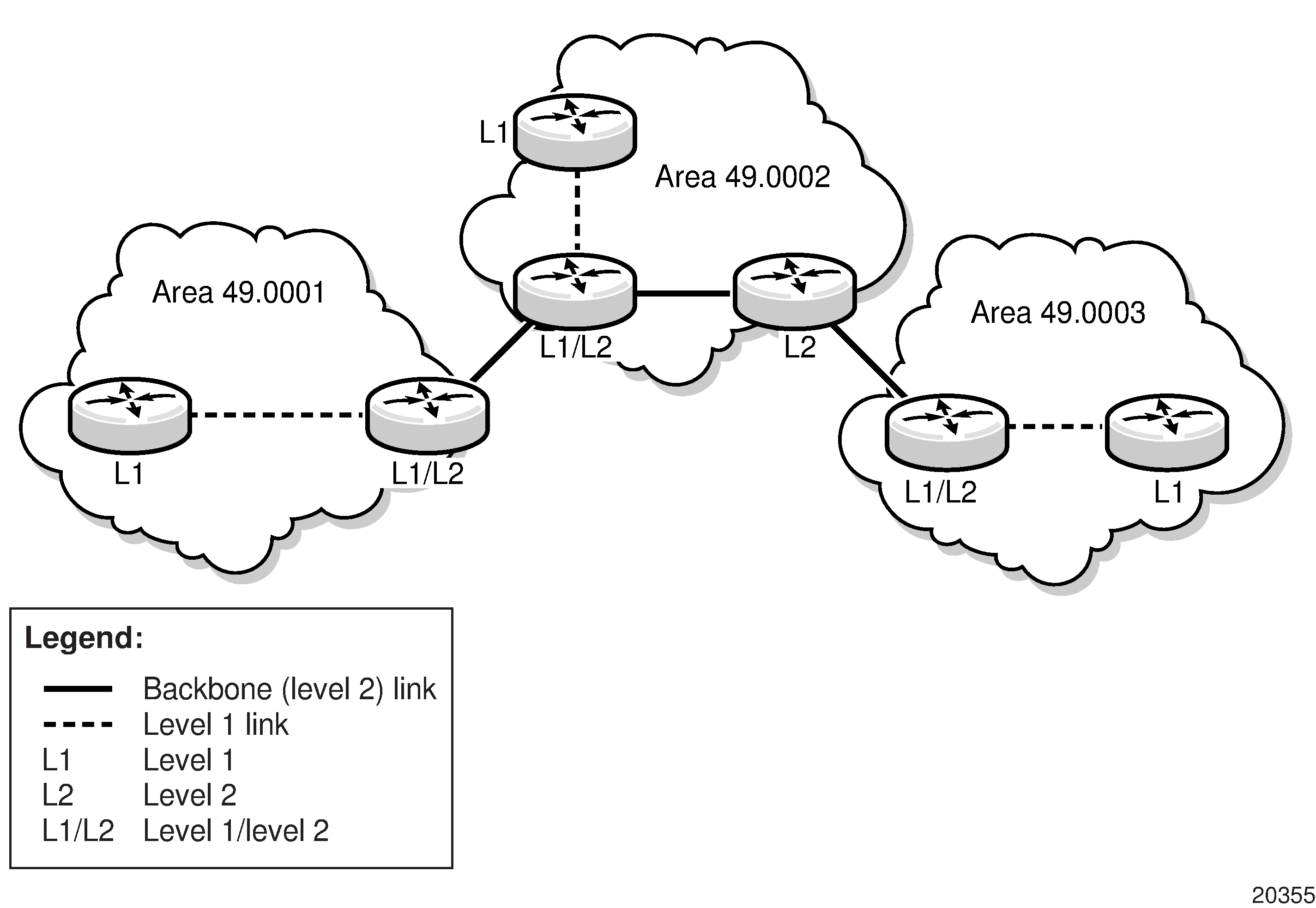
Level 1 routers know the topology in their area, including all routers and end systems, but do not know the identity of routers or destinations outside of their area. To reach a destination outside of the level 1 area, level 1 routers forward the packets to a level 1/2 router in their area as the next hop.
In order for level 1 routers to forward traffic to a level 1/2 router, the level 1/2 router sets the Attached (ATT) bit in its level 1 LSP, which indicates that it is attached to another area, and floods it to all the level 1 neighbors. The level 1 router installs the default route to the level 1/2 router in its routing table. If there is more than one level 1/2 router connected to the level 1 area, the level 1 router only installs the default route of the closest level 1/2 router. The level 1 router then forwards all traffic with a destination outside of its area to this level 1/2 router.
In some cases, users may want to control whether a level 1 router forwards traffic to a specific level 1/2 router; for example, it may be desirable to route around a particular level 1/2 router for traffic engineering reasons. This can be done by configuring a level 1 router to ignore the ATT bit on received level 1 LSPs (using the config>router>isis>ignore-attached-bit command) or configuring a level 1/2 router to suppress the ATT bit on originating level 1 LSPs (using the config>router>isis>suppress-attached-bit command). In the first case, when the level 1 router ignores the ATT bit, it will not install the default route to the level 1/2 router. In the second case, when the level 1/2 router suppresses the ATT bit, all level 1 routers in the area are prevented from installing the default route.
Sometimes the shortest path to an outside destination is not through the closest level 1/2 router, or the only level 1/2 router to forward packets out of an area is not operational. To reduce suboptimal routing, route leaking provides a mechanism to leak (or redistribute) level 2 information into level 1 areas to provide routing information regarding inter-area routes. By distributing more detailed information into the level 1 area, a level 1 router is able to make a better decision as to which level 1/2 router should forward the packet.
The 7705 SAR implementation of IS-IS route leaking is in compliance with RFC 2966, Domain-wide Prefix Distribution with Two-Level IS-IS.
Level 2 routers know the level 2 topology and know which addresses are reachable by each level 2 router. Level 2 routers do not need to know the topology within any level 1 area, except if the level 2 router is also a level 1 router within a single area. By default, only level 2 routers can exchange PDUs or routing information directly with external routers located outside the routing domain.
IS-IS Intermediate Systems describes the router types (or intermediate systems) within IS-IS.
Intermediate System |
Description |
|---|---|
Level 1 |
Maintains a link-state database of other routers that reside in the same area (local area) Exchanges topology information for the local area Routing is performed within the area, based on the area ID portion of the ISO address (see ISO Network Addressing) If the destination address is in the area (area ID is equal), routers forward the packets to the level 1 router that is advertising the destination address, based on the system ID If the destination address is not in the area (area ID is not equal), routers forward the packet to the nearest level 1/2 router in the local area |
Level 2 |
Resides within an area but connects to other level 2 routers in multiple areas in a backbone mesh Maintains a link-state database of other level 2 routers and of the level 1/2 routers in each local area Exchanges topology information between areas Routing is performed between areas based on the area address |
Level 1/2 |
Acts as an area border router with links to the level 2 backbone as well as to the level 1 routers within its area Maintains two link-state databases – a level 1 link-state database of the routers in the local area and a level 2 link-state database of the backbone and any level 1/2 routers Exchanges topology information within the local area and between areas Routing is performed within and between areas If the destination address is in the area (area ID is equal), routers use the level 1 database to forward the packets to the level 1 router that is advertising the destination address, based on the system ID If the destination address is not in the area (area ID is not equal), routers use the level 2 database to forward the packet based on the area ID |
ISO Network Addressing
IS-IS uses ISO network addresses. There are two types of network addresses:
Network Service Access Point (NSAP)
NSAP addresses identify a point of connection to the network, such as a router interface. Each NSAP represents a service that is available at that node. An end system can have multiple NSAP addresses; the addresses differ only by the last byte (called the n-selector). In addition to having multiple services, a single node can belong to multiple areas.
Network Entity Title (NET)
NET addresses identify network layer entities or processes instead of services. Structurally, an NET is identical to an NSAP address but has an n-selector of 00. Most end systems have one NET. Intermediate systems (routers) can have up to three NETs, differentiated by the area ID.
NSAP addresses are divided into three parts. Only the area ID portion is configurable:
area ID – a variable-length field between 1 and 13 bytes that identifies the area to which the router belongs. This field includes the Authority and Format Identifier (AFI) as the first (most significant byte) and the area identifier.
system ID – A 6-byte system identifier. This value is not configurable. The system ID is derived from the system or router ID and uniquely identifies the router.
selector ID – A 1-byte selector identifier that is always 00 for an NET. This value is not configurable.
The area ID portion of the NET can be manually configured with 1 to 13 bytes. If fewer than 13 bytes are entered, the rest of the field is padded with zeros.
Neighbors and Adjacencies
IS-IS routers discover their neighbors by exchanging Hello PDUs. Neighbors are routers that have an interface to a common network/area. In a broadcast-supported topology, one router sends Hello packets to a multicast address and receives Hello packets in return. In non-broadcast topologies, unicast Hello packets are used.
Because all routing devices on a common network must agree on certain parameters, these parameters are included in Hello packets. Differences in these parameters can prevent neighbor relationships from forming.
A level 1 router will not become a neighbor with a node that does not have a common area address. However, if a level 1 router has area addresses A, B, and C, and a neighbor has area addresses B and D, the level 1 router will accept the other node as a neighbor because address B is common to both routers.
When Hello packets have been successfully exchanged, the neighbors are considered to be adjacent.
Within an area, level 1 routers exchange link-state PDUs (LSPs) that identify the IP addresses reachable by each router. Each router has one LSP that contains information about that router; included in each LSP can be zero or more IP addresses, subnet masks, and metric combinations. Each level 1 router is manually configured with the IP address, subnet mask, and metric combinations that are reachable on each interface.
Level 2 routers exchange LSPs that include a complete list of IP addresses, subnet masks, and metrics specifying all the IP addresses that are reachable in their area. Level 2 routers can also report external reachability information, corresponding to addresses reachable by routers in other routing domains or autonomous systems.
Routers with common area addresses form level 1 adjacencies. Routers with no common NET addresses form level 2 adjacencies, if they are capable. See Using Area Addresses to Form Adjacencies.
Level 2 adjacencies are formed with other level 2 nodes whose area addresses do not overlap. If the area addresses do not overlap, the link is considered by both routers to be level 2 and only level 2 LSPs flow on the link.
Designated Routers
In multi-access broadcast networks, such as Ethernet networks, with at least two attached routers, a designated router can be elected. The IS-IS protocol refers to the designated router as the designated intermediate system (DIS).
The concept of a designated router was developed in order to avoid the formation of adjacencies between all attached routers. Without a designated router, the area would be flooded with link-state PDUs (LSPs)—a router would send LSPs to all its adjacent neighbors, and each in turn would send LSPs to all their neighbors, and so on. This would create multiple copies of the same LSP on the same link.
The designated router reduces the number of adjacencies required because each router forms an adjacency only with the designated router. Only the designated router sends LSPs in multicast format to the rest of the network, reducing the amount of routing protocol traffic.
In IS-IS, a broadcast subnetwork with multiple connected routers is considered to be a pseudonode. The pseudonode has links to each of the routers and each of the routers has a single link to the pseudonode (rather than links to each of the other routers). LSPs are generated on behalf of the pseudonode by the DIS.
The DIS has two tasks:
create and update the pseudonode LSP
flood the LSP over the LAN
The DIS is automatically elected based on the interface priority of the router and/or if it has the highest MAC address of all routers in the LAN. If all interface priorities are the same, the router with the highest subnetwork point of attachment (SNPA) is selected. The SNPA is the MAC address on a LAN.
Every IS-IS router interface is assigned both a level 1 priority and a level 2 priority. If a new router starts up in the LAN and has a higher interface priority, the new router preempts the original DIS and becomes the new DIS. The new DIS purges the old pseudonode LSP and floods a new set of LSPs.
Because different priorities can be set according to level 1 or level 2 routing, there can be two different routers in an Ethernet LAN that are DIS-designated. One DIS supports all level 1 routers, and the other DIS supports all level 2 routers on that segment.
The DIS generates the pseudonode LSP. The DIS reports all LAN neighbors (including itself) in the pseudonode link-state PDU (LSP). All LAN routers communicate with the pseudonode via their LSPs. The pseudonode reduces the number of adjacencies by having all physical devices exchange information only with the pseudonode. Each router listens for updates to the pseudonode and updates its individual topology according to those updates.
In point-to-point networks, where a single pair of routers is connected, no designated router is elected. An adjacency must be formed with the neighbor router.
To significantly improve adjacency forming and network convergence, a network should be configured as point-to-point if only two routers are connected, even if the network is a broadcast media such as Ethernet.
IS-IS Packet Types
IS-IS Packet Types describes the packet types used by IS-IS to exchange protocol information.
Packet Type |
Description |
|---|---|
Hello PDUs |
Routers with IS-IS enabled send Hello PDUs to IS-IS-enabled interfaces to discover neighbors and establish adjacencies. |
Link-state PDUs (LSPs) |
LSPs contain information about the state of adjacencies to neighboring IS-IS systems and are used to build the link-state database. LSPs are flooded periodically throughout an area. Level 1 and level 2 LSPs are supported. |
Complete sequence number PDUs (CSNPs) |
In order for all routers to maintain the same information (synchronize), CSNPs inform other routers that some LSPs might be outdated or missing from their database. CSNPs contain a complete list of all LSPs in the current IS-IS database. Level 1 and level 2 CSNPs are supported. |
Partial sequence number PDUs (PSNPs) |
PSNPs are used to request missing LSPs and acknowledge that an LSP was received. Level 1 and level 2 PSNPs are supported. |
When a change takes place, IS-IS sends only the changed information, not the whole topology information or whole link-state database. From the topological database, each router constructs a tree of shortest paths with itself as root (that is, runs the Dijkstra algorithm). IS-IS distributes routing information between routers belonging to a single AS.
To summarize:
Hello PDUs are sent over the IS-IS-enabled interfaces to discover neighbors and establish adjacencies.
IS-IS neighbor relationships are formed if the Hello PDUs contain information that meets the criteria for forming an adjacency.
Routers can build a link-state PDU based upon their local interfaces that are configured for IS-IS and prefixes learned from other adjacent routers.
Routers flood LSPs to the adjacent neighbors except the neighbor from which they received the same LSP. The link-state database is constructed from these LSPs.
A Shortest Path Tree (SPT) is calculated by each router, and from this SPT the routing table is built.
Metrics
IS-IS uses a cost metric that represents the status of a link in an algorithm to determine the best route to a destination. This algorithm is called the Shortest Path First (SPF), or Dijkstra, algorithm. Routing decisions are made using the link-state information. IS-IS evaluates topology changes and, if necessary, performs SPF recalculations.
To calculate the lowest cost to reach a destination, each configured level on each interface must have a cost. The costs for each level on an interface may be different.
In IS-IS, if the metric is not configured, the default cost 10 is used, regardless of the actual capacity of the link. By default, IS-IS does not use reference bandwidth in the calculation, unlike OSPF.
Authentication
Protocol authentication protects against malicious attacks on the communications between routing protocol neighbors. These attacks could either disrupt communications or inject incorrect routing information into the system’s routing table. The use of authentication keys can help to protect routing protocols from these types of attacks.
All IS-IS protocol exchanges can be authenticated. This guarantees that only trusted routers can participate in autonomous system routing.
Authentication must be explicitly configured and can be done using two separate mechanisms:
configuration of an explicit authentication key and algorithm using the authentication-key and authentication-type commands
configuration of an authentication keychain using the auth-keychain command
Either the authentication-key command or the auth-keychain command can be used by IS-IS, but both cannot be supported at the same time. If both commands are configured, the auth-keychain configuration will be applied and the authentication-key command will be ignored.
By default, authentication is not enabled on an interface.
Authentication Key
For explicit authentication keys, IS-IS supports plaintext (simple password) and Message Digest 5 (MD5) authentication.
When authentication is enabled on a link, a text string password must be configured. Neighbor IS-IS routers must supply the password in all IS-IS packets they send to an interface.
Plaintext authentication includes the password in each IS-IS packet sent on a link.
MD5 authentication is more secure than plaintext authentication. MD5 authentication uses the password as an encryption key. Routers in the same routing domain must be configured with the same key. When the MD5 hashing algorithm is used for authentication, MD5 is used to verify data integrity by creating a 128-bit message digest from the data input that is included in each packet. The packet is transmitted to the router neighbor and can only be decrypted if the neighbor has the correct password.
The following authentication commands can be configured in the IS-IS global and IS-IS level contexts:
authentication-key – configures the authentication password used to verify IS-IS protocol packets
authentication-type – enables authentication and specifies the type of authentication to be used, either password or message digest
The following Hello PDU authentication commands can be configured in the IS-IS interface and IS-IS interface level contexts:
hello-authentication-key – configures the authentication password for Hello PDUs
hello-authentication-type – enables Hello authentication and specifies the type of authentication to be used, either password or message digest
Authentication Keychains
The keychain mechanism allows for the creation of keys used to authenticate IS-IS communications. Each keychain entry defines the authentication attributes to be used in authenticating IS-IS messages from remote peers or neighbors; the entry must include at least one key entry to be valid. The keychain mechanism also allows authentication keys to be changed without affecting the state of the IS-IS adjacencies and supports stronger authentication algorithms than plaintext and MD5.
Keychains are configured in the config>system>security>keychain context. For more information about configuring keychains, see the 7705 SAR System Management Guide, ‟TCP Enhanced Authentication and Keychain Authentication”.
The authentication keychain is then associated with IS-IS in the global or level contexts with the auth-keychain command. The Hello authentication keychain is associated with IS-IS in the global, interface, or interface level contexts with the hello-auth-keychain command.
For a key entry to be valid, it must include a valid key, the current system clock value must be within the begin and end time of the key entry, and the algorithm specified must be supported by IS-IS.
IS-IS supports the following authentication algorithms:
clear text password
HMAC-MD5
HMAC-SHA-1
HMAC-SHA-256
Keychain errors are handled as follows.
If a keychain exists but there are no active key entries with an authentication type that matches the type supported by IS-IS, inbound IS-IS packets will not be authenticated and will be discarded and no outbound IS-IS packets will be sent.
If a keychain exists but the last key entry has expired, a log entry will be raised indicating that all keychain entries have expired.
IS-IS protocol requires that the protocol not revert to an unauthenticated state and requires that the old key not be used; therefore, when the last key has expired, all traffic will be discarded.
Route Redistribution and Summarization
Route Redistribution
Route redistribution is the taking of routes from one protocol and sending them to another protocol. The 7705 SAR supports the redistribution of static routes into OSPF and IS-IS and the redistribution of routes between IS-IS levels. The routes can be redistributed as level 1, level 2, or level 1/2 routes, depending on the level capability of the IS-IS router.
Multi-instance IS-IS (MI-IS-IS) supports route redistribution:
to and from any other routing protocol
to and from any other IS-IS instance
Route redistribution involves the use of routing policies. For information about routing policies, see the 7705 SAR Router Configuration Guide, ‟Route Policies”. To configure route redistribution, see Redistributing External IS-IS Routes.
Route Summarization
IS-IS IPv4 route summarization allows users to create aggregate IPv4 addresses that include multiple groups of IPv4 addresses for a given IS-IS level. Routes redistributed from other routing protocols can also be summarized.
IS-IS route summarization helps to reduce the size of the link-state database and the routing table. It also helps to reduce the chance of route flapping, which may occur when a router alternately advertises a destination network via one route then another route in quick sequence (or advertises a route as unavailable then available again).
Partial SPF Calculation
IS-IS supports partial SPF calculation, also referred to as partial route calculation. When an event does not change the topology of the network, IS-IS does not perform full SPF but instead performs an IP reachability calculation for impacted routes. Partial SPF is performed at the receipt of IS-IS LSPs with changes to IP reachability TLVs and, in general, for any IS-IS LSP TLV and sub-TLV change that does not impact the network topology.
IS-IS-TE Extensions
IS-IS traffic engineering (TE) extensions enable the 7705 SAR to include traffic engineering information in the algorithm in order to calculate the best route to a destination. IS-IS-TE extensions are used by MPLS traffic engineering; that is, RSVP-TE. The traffic information includes:
maximum reservable bandwidth
unreserved bandwidth
available bandwidth
link administration groups (or link colors)
SRLGs
TE metrics
Unnumbered Interfaces
IS-IS supports unnumbered point-to-point interfaces with both Ethernet and PPP encapsulations.
Unnumbered interfaces borrow the address from other interfaces such as system, loopback, or another numbered interface, and use it as the source IP address for packets originated from the interface.
This feature supports both dynamic and static ARP for unnumbered interfaces to allow interworking with unnumbered interfaces that may not support dynamic ARP.
An unnumbered interface has IPv4 capability and is used only in cases where IPv4 is active (IPv4-only and mixed IPv4/IPv6 environments). When configuring an unnumbered interface, the interface specified for the unnumbered interface (system or other) must have an IPv4 address. As well, the interface type for the unnumbered interface will automatically be point-to-point.
The unnumbered option can be used in IES and VPRN access interfaces, as well as in a network interface with MPLS support.
Segment Routing in Shortest Path Forwarding
Segment routing adds to IS-IS and OSPF routing protocols the ability to perform shortest path routing and source routing using the concept of abstract segment. A segment can represent a local prefix of a node, a specific adjacency of the node (interface or next hop), a service context, or a specific explicit path over the network. For each segment, the IGP advertises an identifier referred to as a segment ID (SID).
When segment routing is used together with the MPLS data plane, the SID is a standard MPLS label. A router forwarding a packet using segment routing will push one or more MPLS labels.
Segment routing using MPLS labels can be used in both shortest path routing applications and traffic engineering applications. On the 7705 SAR, segment routing implements the shortest path forwarding application.
When a received IPv4 or IPv6 prefix SID is resolved, the segment routing module programs the ILM with a swap operation and programs the LTN with a push operation both pointing to the primary/LFA NHLFE. An IPv4 or IPv6 SR tunnel to the prefix destination is also added to the TTM and is available for use by shortcut applications and Layer 2 or Layer 3 services.
Segment routing introduces the remote LFA feature, which expands the coverage of LFA by computing and automatically programming SR tunnels that are used as backup next hops. The SR shortcut tunnels terminate on a remote alternate node, which provides loop-free forwarding for packets of the resolved prefixes. When the loopfree-alternates option is enabled in an IS-IS instance or in OSPF, SR tunnels are protected with an LFA backup next hop. If the prefix of an SR tunnel is not protected by the base LFA, remote LFA automatically computes a backup next hop using an SR tunnel if the remote-lfa option is also enabled in the IGP instance.
Segment routing can also be used with Layer 3 spoke SDP interfaces to support multicast (PIM only). See Multicast Over Layer 3 Spoke SDP for more information.
Configuring Segment Routing in Shortest Path
Segment routing is enabled in an IGP routing instance using the following sequence of commands.
First, the user configures the global label block, referred to as the Segment Routing Global Block (SRGB), which is reserved for assigning labels to segment routing prefix SIDs originated by this router. This range is within the system dynamic label range and by default is not instantiated:
config>router>mpls-labels>sr-labels start start-value end end-value
Next, the user enables the context to configure segment routing parameters within an IGP instance:
config>router>isis>segment-routing
config>router>ospf>segment-routing
The key parameter is the configuration of the prefix SID index range and the offset label value that this IGP instance uses. Because each prefix SID represents a network global IP address, the SID index for a prefix must be unique network-wide. All routers in the network are expected to configure and advertise the same prefix SID index range for an IGP instance. However, the label value used by each router to represent this prefix, that is, the label programmed in the ILM, can be local to that router by the use of an offset label, referred to as a start label:
Local Label (Prefix SID) = start-label + {SID index}
The label operation in the network is very similar to LDP when operating in independent label distribution mode (RFC 5036), with the difference being that the label value used to forward a packet to each downstream router is computed by the upstream router based on the advertised prefix SID index using the above formula.
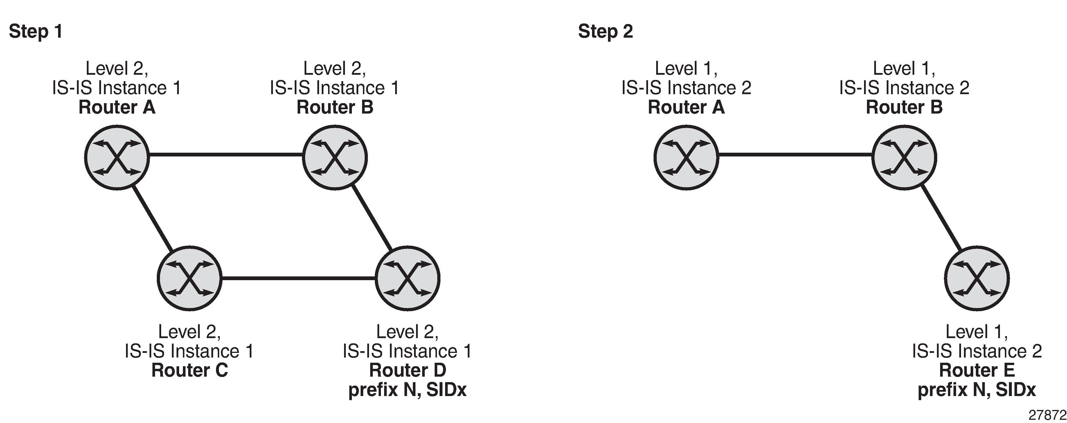
Packet Label Encapsulation using Segment Routing Tunnel is an example of a router advertising its loopback address and the resulting packet label encapsulation throughout the network.
Router N-6 advertises loopback 10.10.10.1/32 with a prefix index of 5. Routers N-1 to N-6 are configured with the same SID index range of [1,100] and an offset label of 100 to 600 respectively. The following are the actual label values programmed by each router for the prefix of PE2.
N-6 has a start label value of 600 and programs an ILM with label 605.
N-3 has a start label value of 300 and swaps incoming label 305 to label 605.
N-2 has a start label value of 200 and swaps incoming label 205 to label 305.
Similar operations are performed by N-4 and N-5 for the bottom path.
N-1 has an SR tunnel to N-6 with two ECMP paths. It pushes label 205 when forwarding an IP or service packet to N-6 via downstream next hop N-2 and pushes label 405 when forwarding via downstream next hop N-4.
The CLI commands for configuring the prefix SID index range and offset label value for an IGP instance are as follows:
config>router>isis>segment-routing>prefix-sid-range {global | start-label label-value max-index index-value}
config>router>ospf>segment-routing>prefix-sid-range {global | start-label label-value max-index index-value}
There are two mutually exclusive modes of operation for the prefix SID range on the router: global mode and per-instance mode.
In the global mode of operation, the user configures the global value and the IGP instance assumes that the start label value is the lowest label value in the SRGB and the prefix SID index range size is equal to the range size of the SRGB. When one IGP instance selects the global option for the prefix SID range, all IGP instances on the system must do the same.
The user must shut down the segment routing context and disable the prefix-sid-range command in all IGP instances in order to change the SRGB. When the SRGB is changed, the user must re-enable the prefix-sid-range command. The SRGB range change fails if an already allocated SID index/label goes out of range.
In the per-instance mode of operation, the user partitions the SRGB into non-overlapping sub-ranges among the IGP instances. The user configures a subset of the SRGB by specifying the start label value and the prefix SID index range size. All resulting net label values (start-label + index) must be within the SRGB or the configuration fails. The 7705 SAR checks for overlaps of the resulting net label value range across IGP instances and strictly enforces no overlapping of the ranges.
The user must shut down the segment routing context of an IGP instance in order to change the SID index/label range of that IGP instance using the prefix-sid-range command. A range change fails if an already allocated SID index/label goes out of range.
The user can, however, change the SRGB without shutting down the segment routing context as long as it does not reduce the current per-IGP instance SID index/label range defined with the prefix-sid-range command. Otherwise, the user must shut down the segment routing context of the IGP instance and disable and re-enable the prefix-sid-range command.
Finally, the user brings up segment routing on the IGP instance by using the no shutdown command:
config>router>isis>segment-routing>no shutdown
config>router>ospf>segment-routing>no shutdown
This command fails if the user has not previously enabled the advertise-router-capability option in the IGP instance. Segment routing capability must be advertised to all routers in a particular domain so that routers that support the capability only program the node SID in the data path toward neighbors that also support it.
config>router>isis>advertise-router-capability {area | as}
config>router>ospf>advertise-router-capability {link | area | as}
The IGP segment routing extensions are area-scoped. The user must therefore configure the flooding scope to area in OSPF and to area or as in IS-IS; otherwise, performing a no shutdown of the segment-routing node will fail.
The segment-routing command and the igp-shortcut and advertise-tunnel-link are mutually exclusive under IGP, because an SR tunnel cannot resolve to an RSVP tunnel next hop.
IS-IS supports node SID indexes or labels on IPv4 and IPv6 interfaces, and OSPF supports node SID indexes or labels on IPv4 addresses only, because OSPFv3 does not support segment routing.
The user assigns a node SID index or label to the prefix representing the primary address of an IPv4 or IPv6 network interface of type loopback using one of the following commands:
config>router>isis>interface>ipv4-node-sid index value
config>router>ospf>area>interface>node-sid index value
config>router>isis>interface>ipv4-node-sid label value
config>router>ospf>area>interface>node-sid label value
config>router>isis>interface>ipv6-node-sid index value
config>router>isis>interface>ipv6-node-sid label value
Only a single node SID can be assigned to an interface. The secondary address of an IPv4 interface cannot be assigned a node SID index and does not inherit the SID of the primary IPv4 address. The same applies to the non-primary IPv6 addresses of an interface.
The above commands will fail if the network interface is not of type loopback or if the interface is defined in an IES or a VPRN context. Assigning the same SID index/label value to the same interface in two different IGP instances is not allowed within the same node.
The value of the label or index SID is taken from the range configured for the IGP instance. When using the global mode of operation, a new segment routing module checks that the same index or label value is not assigned to more than one loopback interface address. When using the per-instance mode of operation, this check is not required because the index, and therefore the label ranges, of IGP instances are not allowed to overlap.
Segment Routing Operational Procedures
Prefix SID Resolution for a Segment Routing Mapping Server
An SR-capable router, including a mapping server and its clients, attempts to resolve each received prefix SID to either an SR tunnel endpoint or an LDP tunnel endpoint as described below.
IP Prefix Resolution
SPF calculates the next hops, up to the maximum value defined by the config>router>ecmp max-ecmp-routes command, to reach a destination node (see the 7705 SAR Router Configuration Guide, ‟IP Router Command Reference”, ‟Router Commands” for more information about this command).
A prefix advertised by multiple nodes that are all reachable with the same cost inherits the next hops, up to the max-ecmp-routes defined value, from the advertising nodes.
The next-hop selection is based on:
the lowest next-hop router ID
the lowest interface index (for parallel links to same router ID)
Each next hop keeps a reference to the destination node from which it was inherited.
Prefix SID Resolution
For a specified prefix, the IGP selects the SID value among multiple advertised values according to the following preference order:
the local intra-area SID owned by this router
the prefix SID sub-TLV advertised within an IP reachability TLV
If multiple SIDs exist, the IGP selects the SID corresponding to the destination router or the ABR with the lowest system ID that is reachable using the first next hop of the prefix.
the IS-IS SID and Label Binding TLV from the mapping server
If multiple SIDs exist, the IGP selects the SID advertised by the mapping server with the lowest system ID.
Note: If a level 1/2 router acts as a mapping server and also readvertises the mapping server prefix SID from other mapping servers, the redistributed mapping server prefix SID is preferred by other routers resolving the prefix; this may result in the mapping server with the lowest system ID not being selected.
the selected SID is used with all ECMP next hops from step1 of IP Prefix Resolution toward all destination nodes or ABR nodes that advertised the prefix.
If duplicate prefix SIDs exist after the above steps are completed, the first SID that is processed is programmed according to its corresponding prefix. Subsequent SIDs cause a duplicate SID trap and are not programmed. The corresponding prefixes are resolved and programmed normally using IP next hops.
SR Tunnel Programming
If the prefix SID is resolved from a prefix SID sub-TLV advertised within an IP reachability TLV, the SR ILM performs a swapping operation to an SR NHLFE as with regular SR tunnel resolution.
If the prefix SID is resolved from a mapping server advertisement, stitching to an LDP FEC is preferred over a swapping operation to an SR next hop.
The LDP FEC can be resolved via a static route or a route within an IS-IS instance. The IS-IS instance does not have to be the same as the IGP instance that advertised the mapping server prefix SID sub-TLV.
The SR next hop is only possible if a route is exported from another IGP instance into the local IGP instance without propagating the prefix SID sub-TLV with the route. Otherwise, when the prefix SID is propagated with the route, the resolution follows step1 above.
Prefix Advertisement and Resolution
When segment routing is successfully enabled in an IS-IS instance or in OSPF, the router performs the following operations. See Control Protocol Changes for details of all TLVs and sub-TLVs for both IS-IS and OSPF protocols.
Advertises the Segment Routing Capability sub-TLV to routers in all areas or levels of this IGP instance. However, only neighbors with which the IGP instance established an adjacency will interpret the SID and label range information and use it for calculating the label to swap to or push for a particular resolved prefix SID.
Advertises the assigned index for each configured node SID in the new prefix SID sub-TLV with the N-flag (node SID flag) set. The segment routing module then programs the incoming label map (ILM) with a pop operation for each local node SID in the data path.
Automatically assigns and advertises an adjacency SID label for each formed adjacency over a network IP interface in the new Adjacency SID sub-TLV. The following points should be considered.
An adjacency SID is advertised for both numbered and unnumbered network IP interfaces.
An adjacency SID is not supported for parallel adjacencies between two IGP neighbors.
An adjacency SID is not advertised for an IES interface because access interfaces do not support MPLS.
The adjacency SID must be unique per instance and per adjacency. Furthermore, IS-IS multi-topology 0 (MT=0, IPv4 unicast) can establish an adjacency for both IPv4 and IPv6 address families over the same link, and in that case, a different adjacency SID is assigned to each next hop. However, the existing IS-IS implementation assigns a single Protect-Group ID (PG-ID) to the adjacency; therefore, when the state machine of a BFD session tracking the IPv4 or IPv6 next hop times out, an action is triggered for the prefixes of both address families over that adjacency.
Note: An IS-IS multi-topology (MT) is a set of independent IP topologies run within a single IS-IS domain. The 7705 SAR supports only MT=0 (see RFC 4971).
The segment routing module programs the incoming label map (ILM) with a swap to an implicit null label operation for each advertised adjacency SID.
Resolves received prefixes, and if a prefix SID sub-TLV exists, the segment routing module programs the ILM with a swap operation and an LTN with a push operation, both pointing to the primary/LFA NHLFE. An SR tunnel is also added to the TTM. If a node SID resolves over an IES interface, the data path is not programmed and a trap is raised. Therefore, only next hops of an ECMP set corresponding to network IP interfaces are programmed in the data path; next hops corresponding to IES interfaces are not programmed. If the user configures the interface as network on one side and IES on the other side, MPLS packets for the SR tunnel received on the access side are dropped.
LSA filtering, causing SIDs not to be sent in one direction which means some node SIDs are resolved in parts of the network upstream of the advertisement suppression.
When the user enables segment routing in an IGP instance, the main SPF and LFA SPF are computed normally and the primary next hop and LFA backup next hop for a received prefix are added to the RTM without the label information advertised in the prefix SID sub-TLV. In all cases, the SR tunnel is not added into the RTM.
Error and Resource Exhaustion Handling
When the prefix corresponding to a node SID is being resolved, the following procedures are followed.
Procedure 1: Providing support of multiple topologies for the same destination prefix
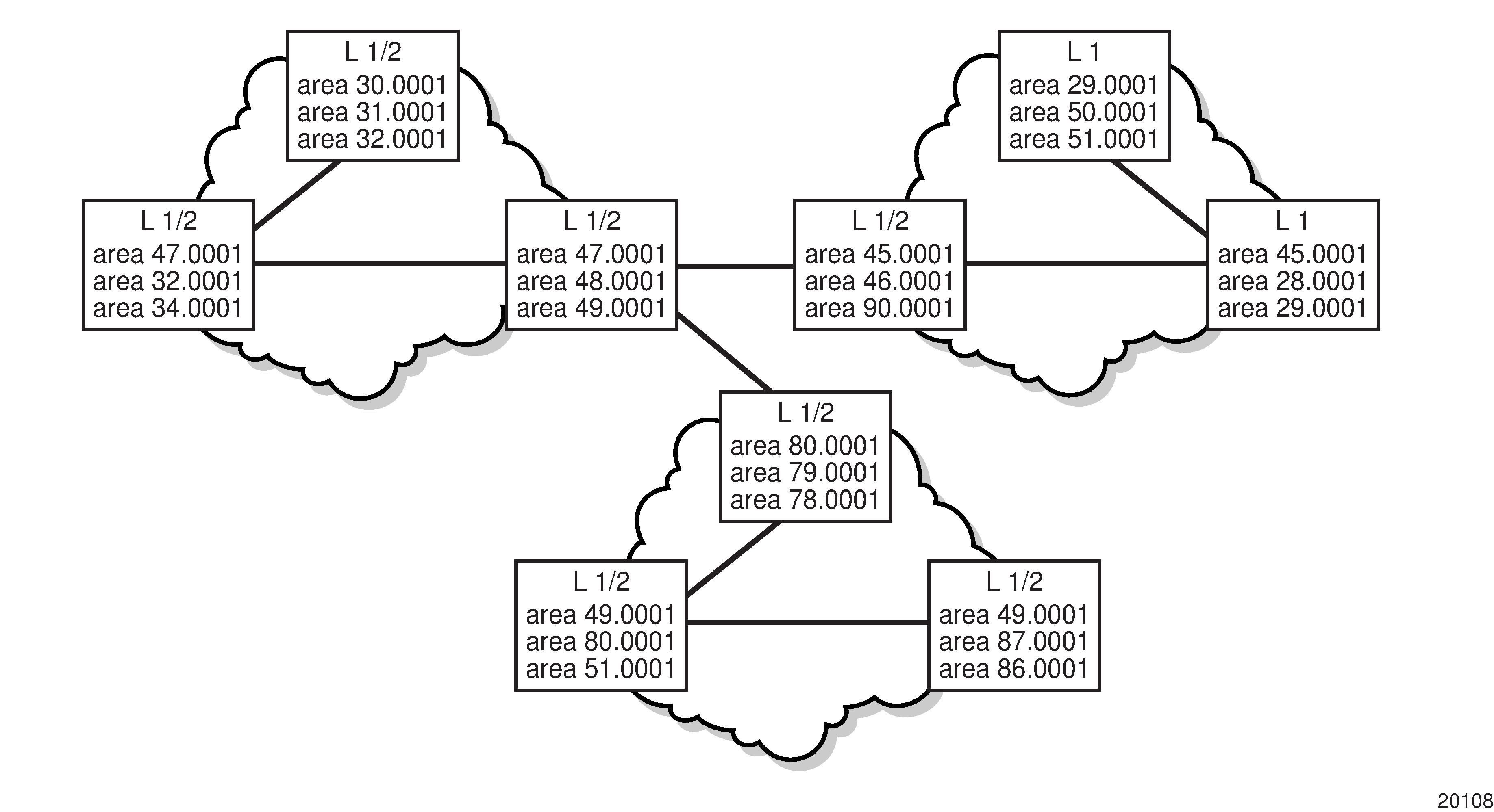
The 7705 SAR supports assigning different prefix SID indexes and labels to the same prefix in different IGP instances. While other routers that receive these prefix SIDs program a single route into the RTM, based on the winning instance ID as per the RTM route type preference, the 7705 SAR adds two tunnels to this destination prefix in the TTM. This provides for the support of multiple topologies for the same destination prefix.
Example:
In two different instances (level 2, IS-IS instance 1 and level1, IS-IS instance 2—see Programming Multiple Tunnels to the Same Destination), Router D has the same prefix destination with different SIDs (SIDx and SIDy).

Assume that the following route type preference in the RTM and tunnel type preference in the TTM are configured:
ROUTE_PREF_ISIS_L1_INTER (RTM) 15
ROUTE_PREF_ISIS_L2_INTER (RTM) 18
ROUTE_PREF_SR_ISIS_TTM 10
Router A performs the following resolution within the single IS-IS instance 1, level 2. All metrics are the same, and ECMP = 2.
For prefix N, the RTM entry is:
prefix N
nhop1 = B
nhop2 = C
preference 18
For prefix N, the SR tunnel TTM entry is:
tunnel-id 1: prefix N-SIDx
nhop1 = B
nhop2 = C
tunl-pref 10
Add IS-IS instance 2 (level 1) in the same setup, but in routers A, B, and C only. Router A performs the resolution.
For prefix N, the RTM entry is:
prefix N
nhop1 = B
preference 15
The RTM prefers level 1 route over level 2 route.
For prefix N, there are two SR tunnel entries in the TTM:
SR entry for level 2:
tunnel-id 1: prefix N-SIDx
nhop1 = B
nhop2= C
tunl-pref 10
SR entry for level 1:
tunnel-id 2: prefix N-SIDy
Procedure 2: Resolving received SID indexes or labels to different routes of the same prefix within the same IGP instance
Two variations of this procedure can occur.
If the 7705 SAR does not allow assigning the same SID index or label to different routes of the same prefix within the same IGP instance, it resolves only one SID index or label if it is received from another SR implementation and based on the RTM active route selection.
If the 7705 SAR does not allow assigning different SID indexes or labels to different routes of the same prefix within the same IGP instance, it resolves only one SID index or label if received from another SR implementation and based on the RTM active route selection.
The selected SID will be used for ECMP resolution to all neighbors. If the route is inter-area and the conflicting SIDs are advertised by different ABRs, ECMP toward all ABRs uses the selected SID.
Procedure 3: Checking for SID errors prior to programming ILM and NHLFE
If any of the following conditions are true, the router logs a trap and generates a syslog error message and will not program the ILM and NHLFE for the prefix SID:
-
the received prefix SID index falls outside the locally configured SID range
-
one or more resolved ECMP next hops for a received prefix SID did not advertise SR Capability sub-TLV
-
the received prefix SID index falls outside the advertised SID range of one or more resolved ECMP next hops
Procedure 4: Programming ILM/NHLFE for duplicate prefix SID indexes/labels for different prefixes
Two variations of this procedure can occur.
For received duplicate prefix SID indexes or labels for different prefixes within the same IGP instance, the router:
programs ILM/NHLFE for the first prefix SID
logs a trap and a syslog error message
does not program the subsequent prefix SID in the data path
For received duplicate prefix SID indexes for different prefixes across IGP instances, there are two options.
In the global SID index range mode of operation, the resulting ILM label values are the same across the IGP instances. The router:
programs ILM/NHLFE for the prefix of the winning IGP instance based on the RTM route type preference
-
logs a trap and a syslog error message
-
does not program the subsequent prefix SIDs in the data path
In the per-instance SID index range mode of operation, the resulting ILM label will have different values across the IGP instances. The router programs ILM/NHLFE for each prefix as expected.
Procedure 5: Programming ILM/NHLFE for the same prefix across IGP instances
The behavior in the case of a global SID index range is illustrated by the IS-IS example in Handling of Same Prefix and SID in Different IS-IS Instances.
In the global SID index range mode of operation, the resulting ILM label values are the same across the IGP instances. The router programs ILM/NHLFE for the prefix of the winning IGP instance based on the RTM route type preference. The router logs a trap and a syslog error message, and does not program the other prefix SIDs in the data path.
In the per-instance SID index range mode of operation, the resulting ILM label has different values across the IGP instances. The router programs ILM/NHLFE for each prefix as expected.
Assume that the following route type preference in the RTM and tunnel type preference in the TTM are configured:
-
ROUTE_PREF_ISIS_L1_INTER (RTM) 15
-
ROUTE_PREF_ISIS_L2_INTER (RTM) 18
-
ROUTE_PREF_SR_ISIS_TTM 10
-
Router A performs the following resolution within the single IS-IS instance 1, level 2. All metrics are the same, and ECMP = 2.
-
For prefix N, the RTM entry is:
-
prefix N
-
nhop1 = B
-
nhop2 = C
-
preference 18
-
-
For prefix N, the SR tunnel TTM entry is:
-
tunnel-id 1: prefix N-SIDx
-
nhop1 = B
-
nhop2 = C
-
tunl-pref 10
-
-
-
Add IS-IS instance 2 (level 1) in the same setup, but in routers A, B, and E only. Router A performs the resolution.
-
For prefix N, the RTM entry is:
-
prefix N
-
nhop1 = B
-
preference 15
The RTM prefers level 1 route over level 2 route.
-
-
For prefix N, there is one SR tunnel entry for level 2 in the TTM:
-
tunnel-id 1: prefix N-SIDx
-
nhop1 = B
-
nhop2 = C
-
tunl-pref 10
-
-
Procedure 6: Handling ILM resource exhaustion while assigning a SID index/label
If the system exhausted an ILM resource while assigning a SID index/label to a local loopback interface, index allocation fails and an error is returned in the CLI. In addition, the router logs a trap and generates a syslog error message.
Procedure 7: Handling ILM, NHLFE, or other IOM or CSM resource exhaustion while resolving or programming a SID index/label
If the system exhausted an ILM, NHLFE, or any other IOM or CSM resource while resolving and programming a received prefix SID or programming a local adjacency SID, the following occurs.
The IGP instance goes into overload and a trap and syslog error message are generated.
The segment routing module deletes the tunnel.
The user must manually clear the IGP overload condition after freeing resources. After the IGP is brought back up, it attempts to program at the next SPF all tunnels that previously failed the programming operation.
Segment Routing Tunnel Management
The segment routing module adds to the TTM a shortest path SR tunnel entry for each resolved remote node SID prefix and programs the data path with the corresponding LTN with the push operation pointing to the primary and LFA backup NHLFEs. The LFA backup next hop for a prefix that was advertised with a node SID will only be computed if the loopfree-alternates option is enabled in the IS-IS instance or in OSPF. The resulting SR tunnel that is populated in the TTM is automatically protected with FRR when an LFA backup next hop exists for the prefix of the node SID.
With ECMP, a maximum of eight primary next hops (NHLFEs) are programmed for the same tunnel destination per IGP instance. ECMP and LFA next hops are mutually exclusive.
The default preference for shortest path SR tunnels in the TTM is set lower than LDP tunnels but higher than BGP tunnels to allow controlled migration of customers without disrupting their current deployment when they enable segment routing. The following is the setting of the default preferences for the various tunnel types. This includes the preference of both SR tunnels based on shortest path (referred to as SR-ISIS and SR-OSPF).
The global default TTM preference for the tunnel types is as follows:
ROUTE_PREF_RSVP 7
ROUTE_PREF_SR_TE 8
ROUTE_PREF_LDP 9
ROUTE_PREF_SR_OSPF_TTM 10
ROUTE_PREF_SR_ISIS_TTM 11
ROUTE_PREF_BGP_TTM 12
ROUTE_PREF_GRE 255
The default value for SR-ISIS is the same regardless of whether one or more IS-IS instances programmed a tunnel for the same prefix. The selection of an SR tunnel in this case is based on the lowest IGP instance ID.
The TTM preference is used for BGP shortcuts, VPRN auto-bind, or BGP transport tunnel when the tunnel binding commands are configured to the any value, which parses the TTM for tunnels in the protocol preference order. The user can choose to either accept the global TTM preference or explicitly list the tunnel types to be used. When the tunnel types are listed explicitly, the TTM preference is still used to select one type over the other. In both cases, a fallback to the next preferred tunnel type is performed if the selected one fails. A reversion to a more preferred tunnel type is performed as soon as one is available. See BGP Label Route Resolution Using Segment Routing Tunnel, and Service Packet Forwarding with Segment Routing for the detailed service and shortcut binding CLI commands.
For SR-ISIS and SR-OSPF, the user can configure the preference of each specific IGP instance away from the above default values.
- CLI Syntax:
config>router>isis>segment-routing>tunnel-table-pref preferenceconfig>router>ospf>segment-routing>tunnel-table-pref preference
Tunnel MTU Determination
The MTU of an SR tunnel populated into the TTM is determined as in the same way as the MTU of an IGP tunnel (for example, LDP LSP), based on the outgoing interface MTU minus the label stack size. Segment routing, however, supports remote LFA, which programs an LFA backup next hop, adding another label to the tunnel for a total of two labels.
The following commands are used to configure the MTU of all SR tunnels within each IGP instance:
- CLI Syntax:
config>router>isis (ospf)>segment-routing>tunnel-mtu bytes
There is no default value for this command. If the user does not configure an SR tunnel MTU, the MTU, in bytes, is fully determined by IGP as follows:
SR_Tunnel_MTU = MIN {Cfg_SR_MTU, IGP_Tunnel_MTU– (1+ frr-overhead)✕4}
where
Cfg_SR_MTU is the MTU configured by the user for all SR tunnels within an IGP instance using the tunnel-mtu command. If no value is configured by the user, the SR tunnel MTU is fully determined by the IGP interface calculation explained in the following bullet point
IGP_Tunnel_MTU is the minimum of the IS-IS or OSPF interface MTU among all the ECMP paths or among the primary and LFA backup paths of this SR tunnel
frr-overhead is set to 1 if the segment-routing and remote-lfa options are enabled in the IGP instance. Otherwise, it is set to 0.
The SR tunnel MTU is dynamically updated whenever any of the above parameters used in its calculation changes. This includes if the set of the tunnel next hops changes or the user changes the configured SR MTU or interface MTU value.
Remote LFA with Segment Routing
Remote LFA for segment routing supports both link protection and node protection. For information about remote LFA for node protection, see Node Protection Support in Remote LFA and TI-LFA.
The remote LFA next-hop calculation by the IGP LFA SPF is enabled with the following command:
- CLI Syntax:
config>router>isis>loopfree-alternates>remote-lfaconfig>router>ospf>loopfree-alternates>remote-lfa
SPF performs the remote LFA additional computation following the regular LFA next-hop calculation when both of the following conditions are met:
the remote-lfa option is enabled in an IGP instance
the LFA next-hop calculation did not result in protection for one or more prefixes resolved to an interface
Remote LFA extends the protection coverage of LFA-FRR to any topology by automatically computing and establishing or tearing down shortcut tunnels, also referred to as repair tunnels, to a remote LFA node that puts the packets back into the shortest path without looping them back to the node that forwarded them over the repair tunnel. A repair tunnel can, in theory, be an RSVP-TE LSP, an LDP-in-LDP tunnel, or an SR tunnel. On the 7705 SAR, this feature is restricted to using an SR repair tunnel to the remote LFA node.
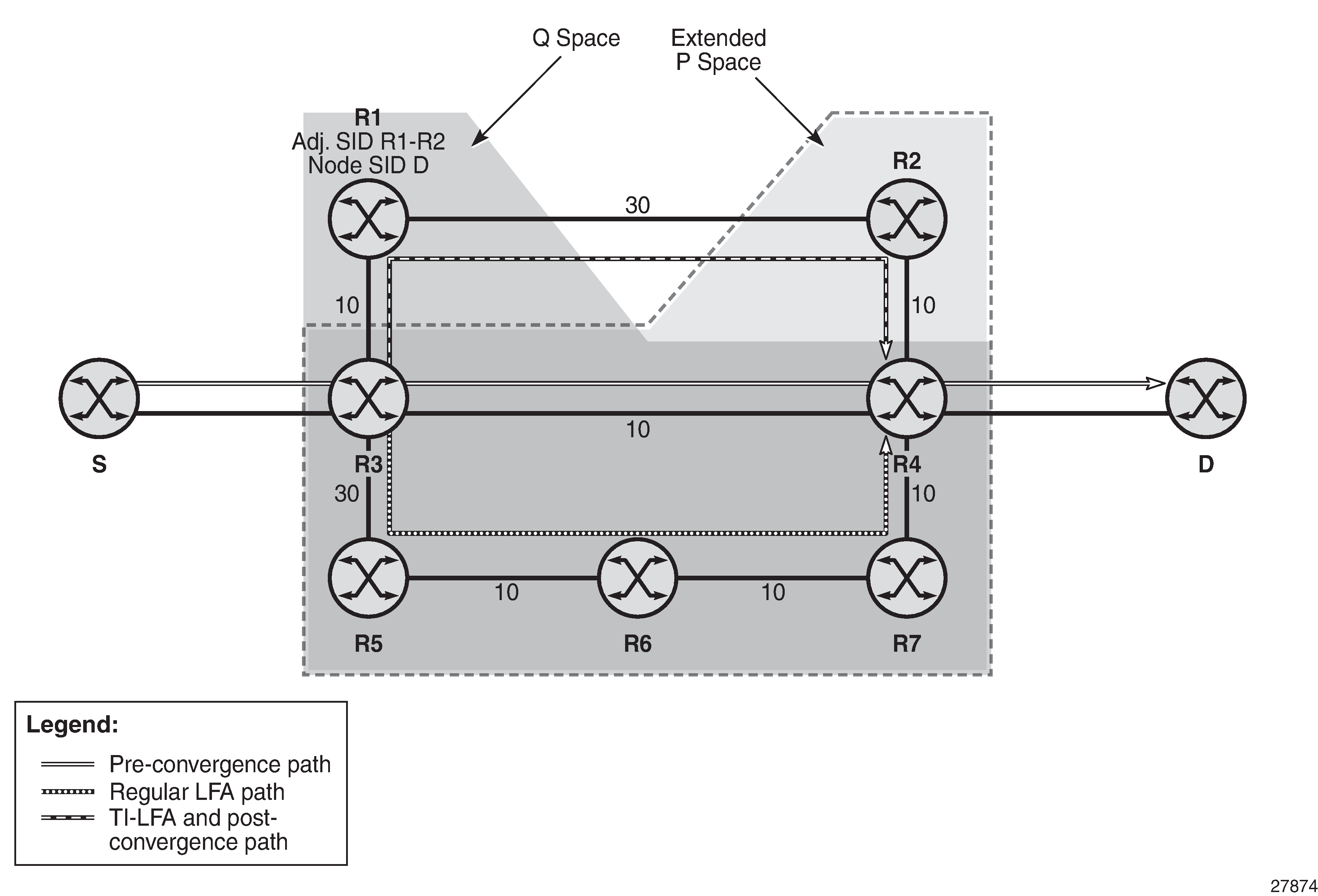
The remote LFA algorithm for link protection is described in RFC 7490, Remote Loop-Free Alternate (LFA) Fast Reroute (FRR). Unlike the regular LFA calculation, which is calculated per prefix, the LFA algorithm for link protection is a per-link LFA SPF calculation. The algorithm provides protection for all destination prefixes which share the protected link by using the neighbor on the other side of the protected link as a proxy for all the destinations. An example is shown in Remote LFA Algorithm.
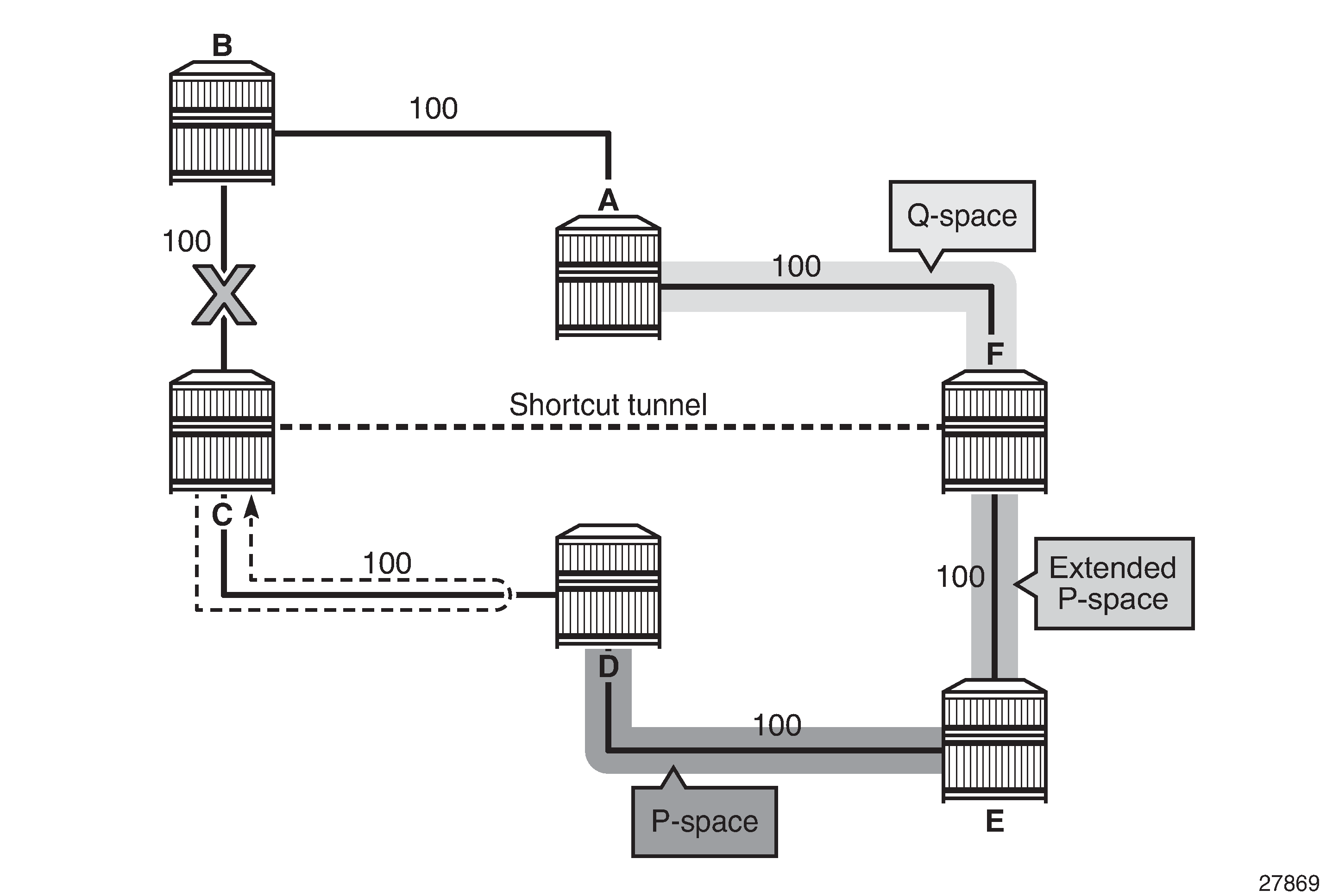
When the LFA SPF in node C computes the per-prefix LFA next hop, prefixes that use link C-B as the primary next hop have no LFA next hop due to the ring topology. If node C used node link C-D as a backup next hop, node D would loop a packet back to node C. Remote LFA then runs the following algorithm, referred to as the ‟PQ Algorithm” in RFC 7490:
The algorithm computes the extended P space of node C with respect to link C-B: the set of nodes reachable from node C without any path transiting the protected link (link C-B). This yields nodes D, E, and F.
The determination of the extended P space by node C uses the same computation as regular LFA by running SPF on behalf of each of the neighbors of C.
Note: RFC 7490 initially introduced the concept of P space, which would have excluded node F because, from the node C perspective, node C has a couple of ECMP paths, one of which goes via link C-B. However, because the remote LFA next hop is activated when link C-B fails, this rule can be relaxed and node F can be included, which then yields the extended P space.The user can limit the search for candidate P nodes to reduce the number of SPF calculations in topologies where many eligible P nodes can exist. A CLI command is provided to configure the maximum IGP cost from node C for a P node to be eligible:
config>router>isis>loopfree-alternates>remote-lfa max-pq-cost value
config>router>ospf>loopfree-alternates>remote-lfa max-pq-cost value
The algorithm computes the Q space of node B with respect to link C-B: the set of nodes from which the destination proxy (node B) can be reached without any path transiting the protected link (link C-B).
The Q-space calculation is effectively a reverse SPF on node B. In general, one reverse SPF is run on behalf of each of the neighbors of C to protect all destinations resolving over the link to the neighbor. This yields nodes F and A in the example in Remote LFA Algorithm.
The user can limit the search for candidate Q nodes to reduce the amount of SPF calculations in topologies where many eligible Q nodes can exist. The above CLI command is also used to configure the maximum IGP cost from node C for a Q node to be eligible.
The algorithm selects the best alternate node: this is the intersection of extended P and Q spaces. The best alternate node or PQ node is node F in the example in Remote LFA Algorithm. From node F onwards, traffic follows the IGP shortest path.
If many PQ nodes exist, the lowest IGP cost from node C is used to narrow down the selection, and if more than one PQ node remains, the node with the lowest router ID is selected.
The details of the label stack encoding when the packet is forwarded over the remote LFA next hop is shown in Remote LFA Next Hop in Segment Routing.
The label corresponding to the node SID of the PQ node is pushed on top of the original label of the SID of the resolved destination prefix. If node C has resolved multiple node SIDs corresponding to different prefixes of the selected PQ node, it pushes the lowest node SID label on the packet when forwarding the packets over the remote LFA backup next hop.
If the PQ node is also the advertising router for the resolved prefix, the label stack is compressed in some cases, depending on the IGP.
In IS-IS, the label stack is always reduced to a single label, which is the label of the resolved prefix owned by the PQ node.
In OSPF, the label stack is reduced to the single label of the resolved prefix when the PQ node advertised a single node SID. If the PQ node advertised a node SID for multiple loopback interfaces within OSPF, the label stack is reduced to a single label only if the SID of the resolved prefix is the lowest SID value.
The following rules and limitations apply to the remote LFA implementation.
LFA policy is currently supported for IP next hops only. It is not supported for tunnel next hops when IGP shortcuts are used for LFA backup. Remote LFA is also a tunnel next hop; therefore, a user-configured LFA policy is not applied in the selection of a remote LFA backup next hop when multiple candidates are available.
As a result, if an LFA policy is applied and does not find an LFA IP next hop for a set of prefixes, the remote LFA SPF runs a search for a remote LFA next hop for the same prefixes. The selected remote LFA next hops, if found, may not satisfy the LFA policy constraints.
If the user excludes a network IP interface from being used as an LFA next hop using the CLI command loopfree-alternate-exclude under the IS-IS or OSPF interface context, the interface is also excluded from being used as the outgoing interface for a remote LFA tunnel next hop.
As with the regular LFA algorithm, the remote LFA algorithm computes a backup next hop to the ABR advertising an inter-area prefix and not to the destination prefix.
Topology-Independent LFA
The Topology-Independent LFA (TI-LFA) feature improves the protection coverage of a network topology by computing and automatically instantiating a repair tunnel to a Q node that is not in the shortest path from the computing node. The repair tunnel uses the shortest path to the P node and a source-routed path from the P node to the Q node.
In addition, the TI-LFA algorithm selects the backup path that matches the post-convergence path. This helps with capacity planning in the network because traffic always flows on the same path when transitioning to the FRR next hop and then to the new primary next hop.
At a high level, the TI-LFA link-protection algorithm searches for the closest Q node to the computing node and then selects the closest P node to this Q node, up to a maximum number of labels. This is performed on each of the post-convergence paths to each destination node or prefix.
TI-LFA supports both link protection and node protection. For information about node protection, see Node Protection Support in Remote LFA and TI-LFA.
TI-LFA Configuration
TI-LFA can be enabled in OSPF or in an IS-IS instance using the following command:
config>router>ospf>loopfree-alternates>ti-lfa [max-sr-frr-labels value]
config>router>isis>loopfree-alternates>ti-lfa [max-sr-frr-labels value]
When the ti-lfa option is enabled in OSP, it provides a TI-LFA link-protect backup for an SR-OSPF IPv4 tunnel or for an IPv4 SR-TE LSP. See more details of the applicability of the various LFA options in LFA Protection Option Applicability.
When the ti-lfa option is enabled in IS-IS, it provides a TI-LFA link-protect backup path in S-IS multi-topology 0 (MT=0) for an SR-ISIS IPv4 or SR-ISIS IPv6 tunnel (node SID and adjacency SID), or for an IPv4 SR-TE LSP. See more details of the applicability of the various LFA options in LFA Protection Option Applicability.
The max-sr-frr-labels parameter limits the search for the LFA backup next hop:
0 — the IGP LFA SPF restricts the search to a TI-LFA backup next hop that does not require a repair tunnel, meaning that the P node and Q node are the same and match a neighbor. This is also the case when both P and Q nodes match the advertising router for a prefix.
1 to 3 — the IGP LFA SPF widens the search to include a repair tunnel to a P node that is connected to the Q nodes with zero to two hops for a total of three labels maximum: one node SID to the P node and two adjacency SIDs from the P node to the Q node. If the P node is a neighbor of the computing node, its node SID is compressed, meaning that up to three adjacency SIDs can separate the P and Q nodes.
2 (default) — corresponds to a repair tunnel to a non-adjacent P node that is adjacent to the Q node. If the P node is a neighbor of the computing node, the node SID of the P node is compressed and the default value of two labels corresponds to two adjacency SIDs between the P and Q nodes.
If the user attempts to change the max-sr-frr-labels parameter to a value that results in a change to the computed FRR overhead, the IGP checks that all SR-TE LSPs can properly account for the overhead based on the configuration of the LSP max-sr-labels and additional-frr-labels parameter values; otherwise, the change is rejected.
The FRR overhead is computed by the IGP and its value is set as follows:
0 if segment-routing is disabled in the IGP instance
-
0 if segment-routing is enabled but remote-lfa is disabled and ti-lfa is disabled
-
1 if segment routing is enabled and remote-lfa is enabled but ti-lfa is disabled, or if segment-routing is enabled, remote-lfa is enabled, and ti-lfa is enabled but ti-lfa max-sr-frr-labels labels is set to 0
-
to the value of ti-lfa max-sr-frr-labels labels, if segment-routing is enabled and ti-lfa is enabled, regardless of whether remote-lfa is enabled or disabled
The LFA commands enable the base LFA feature with the loopfree-alternates command, and optionally add remote LFA with the remote-lfa option and TI-LFA with the ti-lfa option. The behavior when one or more of these options is enabled is explained in TI-LFA Link-Protect Operation. For more information about remote LFA operation, see Node Protection Support in Remote LFA and TI-LFA.
TI-LFA Link-Protect Operation
LFA Protection Option Applicability
Depending on the parameters configured for the loopfree-alternates command, the LFA SPF in an IGP instance runs the algorithms in the following order.
The algorithm first computes a regular LFA for each node and prefix. In this step, a computed backup next hop satisfies any applied LFA policy. This backup next hop protects the specific prefix or node in the context of IP FRR, SR FRR, or SR-TE FRR.
Next, the algorithm always follows with the TI-LFA if the ti-lfa command is enabled for all prefixes and nodes regardless of the outcome of the first step.
With SR FRR and SR-TE FRR, the TI-LFA next hop protects the node SID of that prefix and protects any adjacency SID terminating on the node SID of that prefix.
Finally, the algorithm runs remote LFA only for the next hop of prefixes and nodes that remain unprotected after the first and second steps if the remote-lfa command is enabled.
When protecting an adjacency SID, a parallel ECMP adjacency takes precedence over any other type of LFA backup path. Applying the above algorithm applicability rules results in the following selection:
adjacency SID of an alternate ECMP next hop
TI-LFA backup next hop
LFA backup next hop
remote LFA backup next hop
TI-LFA Algorithm
At a high level, the TI-LFA link-protection algorithm searches for the closest Q node to the computing node and then selects the closest P node to this Q node, up to the number of labels corresponding to the value of ti-lfa max-sr-frr-labels labels, on each of the post-convergence paths to each destination node or prefix. Selecting Link-Protect TI-LFA Backup Path shows a topology where router R3 computes a TI-LFA next hop for protecting link R3-R4.
For each destination node D:
The algorithm computes the post-convergence SPF on the topology without the protected link.
In Selecting Link-Protect TI-LFA Backup Path, R3 finds a single post-convergence path to destination D via R1.
The post-convergence SPF does not include IGP shortcut tunnels, unless advertised as forwarding adjacencies.
The algorithm computes the extended P space of R3 with respect to protected link R3-R4 on the post-convergence paths.
This is the set of nodes Yi in the post-convergence paths that are reachable from R3 neighbors without any path transiting the protected link R3-R4.
R3 computes an LFA SPF rooted at each of its neighbors within the post-convergence paths, that is, R1, using the following equation:
Distance_opt(R1, Yi) < Distance_opt(R1, R3) + Distance_opt(R3, Yi)
where ‟Distance_opt(A, B)” is the shortest distance between two nodes, A and B. The extended P-space calculation yields only node R1.
The algorithm computes the Q space of R3 with respect to protected link R3-R4 in the post-convergence paths.
This is the set of nodes Zi in the post-convergence paths from which the neighbor node R4 of the protected link, acting as a proxy for all destinations D, can be reached without any path transiting the protected link R3-R4.
Distance_opt(Zi, R4) < Distance_opt(Zi, R3) + Distance_opt(R3, R4)
The Q-space calculation yields nodes R2 and R4.
This is the same computation of the Q space performed by the remote LFA algorithm, except that the TI-LFA Q-space computation is performed only on the post-convergence.
For each post-convergence path, the algorithm searches for the closest Q node and selects the closest P node to this Q node, up to the number of labels corresponding to the value of ti-lfa max-sr-frr-labels labels.
In the topology in Selecting Link-Protect TI-LFA Backup Path, there is a single post-convergence path, and a single P node (R1), and the closest of the two found Q nodes to the P node is R2.
R3 installs the repair tunnel to the P-Q set and includes the node SID of R1 and the adjacency SID of the adjacency over link R1-R2 in the label stack. Because the P node R1 is a neighbor of the computing node R3, the node SID of R1 is not needed and the label stack of the repair tunnel is compressed to the adjacency SID over link R1-R2 as shown in Selecting Link-Protect TI-LFA Backup Path.
When a P-Q set is found on multiple ECMP post-convergence paths, the following selection rules are applied, in ascending order, to select a set from a single path:
the lowest number of labels
the lowest next-hop router ID
the lowest interface index if the same next-hop router ID is the same
If multiple links with adjacency SIDs exist between the selected P node and the selected Q node, the following rules are used to select one link:
the adjacency SID with the lowest metric
the adjacency SID with the lowest SID value if the lowest metric is the same
TI-LFA Feature Interactions and Limitations
The following are feature interactions and limitations of TI-LFA link protection.
Enabling the ti-lfa option in an IS-IS instance or for OSPF overrides the user configuration of the loopfree-alternate-exclude command under the interface context in the IGP instance. In other words, the TI-LFA SPF uses that interface as a backup next hop if it matches the post-convergence next hop.
Any prefix excluded from LFA protection using the loopfree-alternates>exclude>prefix-policy prefix-policy command under the IGP instance context is also excluded from TI-LFA.
Because the post-convergence SPF does not use paths transiting on a node in IS-IS overload, the TI-LFA backup path automatically will not transit on such a node.
As with remote LFA, a user-configured LFA policy is not applied in the selection of a TI-LFA backup next hop when multiple candidates are available.
IES interfaces are skipped in TI-LFA computations because they do not support segment routing with MPLS encapsulation. If the only found TI-LFA backup next hop matches an IES interface, the IGP will treat this as if there were no TI-LFA backup paths and will fall back to using either a remote LFA or regular LFA backup path as per the selection rules in LFA Protection Option Applicability.
When the TI-LFA feature provides link protection only, if the protected link is a broadcast interface, the TI-LFA algorithm only guarantees protection of that link and not of the pseudonode corresponding to that shared subnet. In other words, if the pseudonode is in the post-convergence path, the TI-LFA backup path may still traverse the pseudonode. For example, node E in TI-LFA Backup Path via a Pseudonode computes a TI-LFA backup path to destination D via E-C-PN-D because it is the post-convergence path when excluding link E-PN from the topology. This TI-LFA backup does not protect against the failure of the pseudonode (PN).
When the computing router selects an adjacency SID among a set of parallel adjacencies between the P and Q nodes, the selection rules in step 4 of TI-LFA Algorithm are used. However, these rules may not yield the same interface that the P node would have selected in its post-convergence SPF because the latter is based on the lowest value of the locally managed interface index.
For example, node A in Parallel Adjacencies between P and Q Nodes computes the link-protect TI-LFA backup path for destination node E as path A-C-E, where C is the P node and E is the Q node and destination. C has a pair of adjacency SIDs with the same metric to E. Node A selects the adjacency over the point-to-point link C-E because it has the lowest SID value, but node C may select the interface C-PN in its post-convergence path calculation if that interface has a lower interface index than point-to-point link C-E.
Figure 10. Parallel Adjacencies between P and Q Nodes 
Data Path Support
The TI-LFA repair tunnel can have a maximum of three additional labels pushed in addition to the label of the destination node or prefix. The user can set a lower maximum value for the additional FRR labels by configuring the ti-lfa max-sr-frr-labels labels option. The default value is 2.
The data path models the backup path like an SR-TE LSP and therefore uses a super-NHLFE pointing to the NHLFE of the first hop in the repair tunnel. That first hop corresponds to either an adjacency SID or a node SID of the P node.
There is a special case where the P node is adjacent to the node computing the TI-LFA backup, and the Q node is the same as the P node or adjacent to the P node. In this case, the data path at the computing router pushes either zero labels or one label for the adjacency SID between the P and Q nodes. The backup path uses a regular NHLFE in this case as in base LFA or remote LFA. Selecting Link-Protect TI-LFA Backup Path shows an example of a single label in the backup NHLFE.
Node Protection Support in Remote LFA and TI-LFA
The 7705 SAR supports extensions to the LFA algorithm so that remote LFA and TI-LFA can be used for node protection in addition to link protection.
When node protection is enabled, the router prefers a node-protect repair tunnel over a link-protect repair tunnel for a prefix if both tunnels are found in the remote LFA or TI-LFA SPF computations; however, the SPF computation may only find a link-protect repair tunnel for prefixes owned by the protected node.
Configuring Remote LFA and TI-LFA for Node Protection
The node protection calculation for remote LFA and TI-LFA is enabled with the following commands:
config>router>isis>loopfree-alternates>remote-lfa [max-pq-cost value]>node-protect [max-pq-nodes value]
config>router>isis>loopfree-alternates>ti-lfa [max-sr-frr-labels value]>node-protect
config>router>ospf>loopfree-alternates>remote-lfa>node-protect [max-pq-cost value]
config>router>ospf>loopfree-alternates>ti-lfa [max-sr-frr-labels value]>node-protect
The max-pq-nodes parameter in the remote-lfa command controls the maximum number of candidate PQ nodes found in the LFA SPFs for which the node protection check is performed. The node-protect condition means that the router must run the original remote LFA algorithm for link protection plus one extra forward SPF on behalf of each PQ node found, potentially after applying the max-pq-cost parameter, to verify that the path from the PQ node to the destination does not traverse the protected node. Setting the max-pq-nodes parameter to a lower value means that the LFA SPFs use less computation time and resources; however, this may result in not finding a node-protect repair tunnel.
TI-LFA Node-Protect Operation
The 7705 SAR supports the node-protect extensions to the TI-LFA algorithm as described in draft-bashandy-rtgwg-segment-routing-ti-lfa-05. Application of the TI-LFA Algorithm for Node Protection shows a simple topology that illustrates the operation of the TI-LFA algorithm for node protection.
In Application of the TI-LFA Algorithm for Node Protection, for each destination prefix D, R1 programs the TI-LFA repair tunnel (max-sr-frr-labels=1):
For prefixes other than those owned by nodes R2 and R3, R1 programs a node-protect repair tunnel to the P-Q pair R3-R6 by pushing the SID of adjacency R3-R6 on top of the SID for destination D and programming a next hop of R3.
For prefixes owned by node R2, R1 runs the link-protect TI-LFA algorithm and programs a simple link-protect repair tunnel that consists of a backup next hop of R3 and pushes no additional label on top of the SID for the destination prefix.
Prefixes owned by node R3 are not impacted by the failure of R2 because their primary next hop is R3.
The topology computation for Application of the TI-LFA Algorithm for Node Protection is as follows:
The algorithm computes the post-convergence SPF on the topology without the protected node.
R1 computes TI-LFA on the topology without the protected node R2 and finds a single post-convergence path to destination D via R3 and R6. Prefixes owned by all other nodes in the topology have a post-convergence path via R3 and R6 except for prefixes owned by node R2. The latter uses the link R3-R2 and they can only benefit from link protection.
The algorithm computes the extended P space of R1 with respect to protected node R2 on the post-convergence paths. This is the set of nodes Yi in the post-convergence paths that are reachable from R1 neighbors, other than protected node R2, without any path transiting the protected node R2.
R1 computes an LFA SPF rooted at each of its neighbors within the post-convergence paths (for example, R3) using the following equation:
Distance_opt(R3, Yi) < Distance_opt(R3, R2) + Distance_opt(R2, Yi)
where Distance_opt(A,B) is the shortest distance between A and B
The extended P-space calculation yields node R3 only.
The algorithm computes the Q space of R1 with respect to protected link R1-R2 on the post-convergence paths. This is the set of nodes Zi in the post-convergence paths from which node R2 can be reached without any path transiting the protected link R1-R2. The algorithm uses the following equation:
Distance_opt(Zi, R2) < Distance_opt(Zi, R1) + Distance_opt(R1, R2)
The reverse SPF for the Q-space calculation is the same as in the link-protect algorithm and uses the protected node R2 as the proxy for all destination prefixes. If the Q space is computed with respect to the protected node R2 instead of link R1-R2, a reverse SPF would have to be done to each destination D, which is very costly and would not scale. However, computing the Q space with respect to link R1-R2 means that the algorithm only guarantees that the path from the computing node to the Q node is node-protecting. The path from the Q node to the destination D is not guaranteed to avoid the protected node R2. The intersection of the Q space with the post-convergence path is modified in the next step to mitigate this risk.
This step yields nodes R3, R4, R5, and R6.
For each post-convergence path, the algorithm searches for the closest Q node to destination D and selects the closest P node to this Q node, up to the number of labels corresponding to the value configured for the ti-lfa max-sr-frr-labels parameter.
This step yields the following P-Q sets depending on the configuration of max-sr-frr-labels:
When max-sr-frr-labels=0, R3 is the closest Q node to the destination D and R3 is the only P node. This case is the one that results in link protection via PQ node R3.
When max-sr-frr-labels=1, R6 is the closest Q node to the destination D and R3 is the only P node. The repair tunnel for this case uses the SID of the adjacency over link R3-R6 as shown in Application of the TI-LFA Algorithm for Node Protection.
When max-sr-frr-labels=2, R5 is the closest Q node to the destination D and R3 is the only P node. The repair tunnel for this case uses the SIDs of the adjacencies over links R3-R6 and R6-R5.
When max-sr-frr-labels=3, R4 is the closest Q node to the destination D and R3 is the only P node. The repair tunnel for this case uses the SIDs of the adjacencies over links R3-R6, R6-R5, and R5-R4.
Note: This step of the algorithm is modified from the link protection algorithm, which prefers Q nodes that are closest to the computing router R1. This modification minimizes the probability that the path from the Q node to the destination D goes via the protected node R2 as described in step 2. There is, however, still a possibility that the found P-Q set achieves link protection only.The algorithm selects the P-Q set. If a candidate P-Q set is found on each of the multiple ECMP post-convergence paths in step 4, the following rules are applied in ascending order to select a single set:
lowest number of labels
lowest next-hop router ID
lowest interface index if the next-hop router ID is the same
If multiple parallel links with adjacency SIDs exist between the P and Q nodes of the selected P-Q set, the following rules are used to select one of the links:
use the adjacency SID with the lowest metric
use the adjacency SID with the lowest SID value if the lowest metric is the same
Remote LFA Node-Protect Operation
The 7705 SAR supports the node-protect extensions to the remote LFA algorithm as described in RFC 8102.
Remote LFA follows a similar algorithm to TI-LFA but does not limit the scope of the calculation of the extended P space and the Q space to the post-convergence paths.
Remote LFA adds an extra forward SPF on behalf of the PQ node, to ensure that for each destination the selected PQ node does not use a path via the protected node.
Application of the Remote LFA Algorithm for Node Protection shows the application of the remote LFA algorithm for node protection with a slightly modified typology from that shown in Application of the TI-LFA Algorithm for Node Protection. A new node, R7, is added to the top ring and the metric for link R3-R6 is changed to 100.
When the algorithm for remote LFA for node protection is applied to the topology shown in Application of the Remote LFA Algorithm for Node Protection, it performs the following steps:
The algorithm computes the extended P space of R1 with respect to protected node R2.
This is the set of nodes Yi that are reachable from R1 neighbors, other than protected node R2, without any path transiting the protected node R2.
R1 computes an LFA SPF rooted at each of its neighbors, in this case R7, using the following equation:
Distance_opt(R7, Yi) < Distance_opt(R7, R2) + Distance_opt(R2, Yi)
where Distance_opt(A,B) is the shortest distance between A and B
Nodes R7, R3, and R6 satisfy this inequality.
The algorithm computes the Q space of R1 with respect to protected link R1-R2.
This is the set of nodes Zi from which node R2 can be reached without any path transiting the protected link R1-R2. The following equation is used:
Distance_opt(Zi, R2) < Distance_opt(Zi, R1) + Distance_opt(R1, R2)
The reverse SPF for the Q-space calculation is the same as in the remote LFA link-protect algorithm and uses the protected node R2 as the proxy for all destination prefixes.
This step yields nodes R3, R4, R5, and R6.
Therefore, the candidate PQ nodes after this step are nodes R3 and R6.
For each PQ node found, the algorithm runs a forward SPF to each destination D.
This step is required to select only the subset of PQ nodes that do not traverse protected node R2.
Distance_opt(PQi, D) < Distance_opt(PQi, R2) + Distance_opt(R2, D)
Of the candidate PQ nodes R3 and R6, only PQ node R6 satisfies this inequality.
Note: This step of the algorithm is applied to the subset of candidate PQ nodes from steps 1 and 2 to which the parameter max-pq-cost was already applied. This subset is further reduced in this step by retaining the candidate PQ nodes that provide the highest coverage among all protected nodes in the topology while not exceeding the number of nodes set with the max-pq-nodes parameter.If multiple candidate PQ nodes are yielded out of this step, the detailed selection rules of a single PQ node from the candidate list are described in step4.
The algorithm selects a PQ node.
If multiple PQ nodes satisfy the criteria in all the above steps, R1 further selects the PQ node as follows:
R1 selects the lowest IGP cost from R1.
If more than one PQ node remains, R1 selects the PQ node reachable via the neighbor with the lowest router ID (OSPF) or system ID (IS-IS).
If more than one PQ remains, R1 selects the PQ node with the lowest router ID (OSPF) or system ID (IS-IS).
For each destination prefix D, R1 programs the remote LFA backup path as follows:
For prefixes of R5 or R4 or downstream of R4, R1 programs a node-protect remote LFA repair tunnel to the PQ node R6 by pushing the SID of node R6 on top of the SID for destination D and programming a next hop of R7.
For prefixes owned by node R2, R1 runs the link-protect remote LFA algorithm and programs a simple link-protect repair tunnel that consists of a backup next hop of R7 and pushes the SID of PQ node R3 on top of the SID for the destination prefix D.
Prefixes owned by nodes R7, R3, and R6 are not impacted by the failure of R2 because their primary next hop is R7.
TI-LFA and Remote LFA Node Protection Feature Interactions and Limitations
LFA Protection Option Applicability describes the order of activation of the various LFA types on a per-prefix basis: TI-LFA, followed by base LFA, followed by remote LFA.
Node protection is enabled for TI-LFA and remote LFA separately. The base LFA prefers node protection over link protection.
The order of activation of the LFA types supersedes the protection type (node versus link). Consequently, a prefix may be programmed with a link-protect backup next hop by the more preferred LFA type. For example, a prefix could be programmed with the only link-protect backup next hop found by the base LFA while there exists a node-protect remote LFA next hop.
IPv6 Segment Routing using MPLS Encapsulation
This feature implements support for SR IPv6 tunnels in IS-IS MT=0. The user can configure a node SID for the primary IPv6 global address of a loopback interface, which then gets advertised in IS-IS. IS-IS automatically assigns and advertises an adjacency SID for each adjacency with an IPv6 neighbor. After the node SID is resolved, it is used to install an IPv6 SR-ISIS tunnel in the TTM for use by the services.
IS-IS MT=0 Extensions
The IS-IS MT=0 extensions consist of supporting the advertising and resolution of the prefix SID sub-TLV within the IP reachability TLV-236 (IPv6), which is defined in RFC 5308.The adjacency SID is still advertised as a sub-TLV of the Extended IS Reachability TLV 22, as defined in RFC 5305, IS-IS Extensions for Traffic Engineering, as in the case of an IPv4 adjacency. The router sets the V-Flag and I-Flag in the SR-Capabilities sub-TLV to indicate that it is capable of processing SR MPLS-encapsulated IPv4 and IPv6 packets on its network interfaces.
Supported Service and Forwarding Contexts
The service and forwarding contexts supported with SR-ISIS IPv6 tunnels are:
-
SDP of type sr-isis with far-end option using IPv6 address
-
VLL, VPLS, IES/VPRN spoke-SDP interfaces, r-VPLS
-
PW redundancy within Epipe/Ipipe VLLs, Epipe spoke-SDP termination on VPLS and r-VPLS, and Epipe/Ipipe spoke-SDP termination on IES/VPRN
-
remote mirroring
Services Using SDP with an SR IPv6 Tunnel
The MPLS SDP of type sr-isis with a far-end option using an IPv6 address is supported. The SDP must have the same IPv6 far-end address, used by the control plane for the T-LDP session, as the prefix of the node SID of the SR IPv6 tunnel.
- Example:
configureservice[no] sdp sdp-id mpls[no] far-end ipv6-addresssr-isisno sr-isis
The bgp-tunnel, lsp, sr-te lsp, sr-ospf, and mixed-lsp-mode commands are blocked within the SDP configuration context when the far-end address is an IPv6 address.
SDP admin groups are not supported with an SDP using an SR IPv6 tunnel, or with SR-OSPF for IPv6 tunnels, and their assignment is blocked in the CLI.
Services that use an LDP control plane such as T-LDP VPLS and r-VPLS, VLL, and IES/VPRN spoke-SDP interfaces have the spoke SDP (PW) signaled with an IPv6 T-LDP session because the far-end option is configured to an IPv6 address. The spoke SDP for these services binds to an SDP that uses an SR IPv6 tunnel where the prefix matches the far-end address. The 7705 SAR also supports the following:
the IPv6 PW control word with both data plane packets and VCCV OAM packets
The PW switching feature is not supported with LDP IPv6 control planes. As a result, the CLI does not allow the user to enable the vc-switching option whenever one or both spoke SDPs uses an SDP that has the far-end configured as an IPv6 address.
Layer 2 services that use the BGP control plane, such as dynamic MS-PW, cannot bind to an SR IPv6 tunnel because a BGP session to a BGP IPv6 peer does not support advertising an IPv6 next hop for the Layer 2 NLRI. As a result, these services will not auto-generate SDPs using an SR IPv6 tunnel.
The Shortest Path Bridging (SPB) feature works with spoke SDPs bound to an SDP that uses an SR IPv6 tunnel.
Data Path Support
A packet received with a label matching either a node SID or an adjacency SID is forwarded according to the ILM type and operation, as described in Data Path Support .
Label type |
Operation |
|---|---|
Top label is a local node SID |
Label is popped and the packet is further processed If the popped node SID label is the bottom of stack label, the IP packet is looked up and forwarded in the appropriate FIB |
Top or next label is a remote node SID |
Label is swapped to the calculated label value for the next hop and forwarded according to the primary or backup NHLFE With ECMP, a maximum of 8 primary next hops (NHLFEs+) are programmed for the same destination prefix and for each IGP instance. ECMP and LFA next hops are mutually exclusive |
Top or next label is an adjacency SID |
Label is popped and the packet is forwarded out on the interface to the next hop associated with this adjacency SID label In effect, the data path operation is modeled like a swap to an implicit-null label instead of a pop |
Next label is a BGP 3107 label |
The packet is further processed according to the ILM operation in the current implementation:
|
Next label is a service label |
The packet is looked up and forwarded in the Layer 2 or VPRN FIB |
A router forwarding an IP or a service packet over an SR tunnel pushes a maximum of two transport labels with a remote LFA next hop. This is illustrated in Transport Label Stack in Shortest Path Forwarding with Segment Routing.
In Transport Label Stack in Shortest Path Forwarding with Segment Routing, a VPRN service in node B forwards a packet received on a SAP to a destination VPN-IPv4 prefix X advertised by a remote PE2 via ASBR/ABR node A. Router B is in a segment routing domain while PE2 is in an LDP domain. BGP label routes are used to distribute the PE /32 loopbacks between the two domains.
When node B forwards a packet over the primary next hop for prefix X, it pushes the node SID of the ASBR followed by the BGP 3107 label for PE2, followed by the service label for prefix X. When the remote LFA next hop is activated, node B pushes one or more segment routing labels: the node SID for the remote LFA backup node (node N).
When node N receives the packet while the remote LFA next hop is activated, it pops the top segment routing label, which corresponds to a local node SID. Th packet is then forwarded to the ASBR node over the shortest path (link N-Z).
When the ABR/ASBR node receives the packet from either node B or node Z, it pops the segment routing label that corresponds to a local node SID, then swaps the BGP label and pushes the LDP label of PE2, which is the next hop of the BGP label route.
Control Protocol Changes
This section describes both IS-IS Control Protocol Changes and OSPF Control Protocol Changes.
IS-IS Control Protocol Changes
New TLV/sub-TLVs are defined in draft-ietf-isis-segment-routing-extensions and are supported in the implementation of segment routing in IS-IS:
the prefix SID sub-TLV
the adjacency SID sub-TLV
the SID/Label Binding TLV
SR-Capabilities sub-TLV
SR-Algorithm sub-TLV
This section describes the behaviors and limitations of IS-IS support of segment routing TLV and sub-TLVs.
The 7705 SAR supports advertising the IS-IS router capability TLV (RFC 4971) only for topology MT=0. As a result, the segment routing capability sub-TLV can only be advertised in MT=0, which restricts the segment routing feature to MT=0.
Similarly, if prefix SID sub-TLVs for the same prefix are received in different MT numbers of the same IS-IS instance, only the one in MT=0 is resolved. If the prefix SID index is also duplicated, an error is logged and a trap is generated, as explained in Error and Resource Exhaustion Handling.
The I and V flags are both set to 1 when originating the SR capability sub-TLV to indicate support for processing both SR MPLS-encapsulated IPv4 and IPv6 packets on its network interfaces. These flags are not checked when the sub-TLV is received. Only the SRGB range is processed.
Both IPv4 and IPv6 prefix and adjacency SID sub-TLVs originate within MT=0.
The 7705 SAR originates a single prefix SID sub-TLV per IS-IS IP reachability TLV and processes the first prefix SID sub-TLV only if multiple SID sub-TLVs are received within the same IS-IS IP reachability TLV.
The 7705 SAR encodes the 32-bit index in the prefix SID sub-TLV. The 24-bit label is not supported.
The 7705 SAR originates a prefix SID sub-TLV with the following encoding of the flags and the following processing rules.
The R-flag is set if the prefix SID sub-TLV, along with its corresponding IP reachability TLV, is propagated between levels. See below for more details about prefix propagation.
The N-flag is always set because the 7705 SAR supports prefix SID of type node SID only.
The P-flag (no-PHP flag) is always set, meaning that the label for the prefix SID is pushed by the PHP router when forwarding to this router. The 7705 SAR PHP router properly processes a received prefix SID with the P-flag set to zero and uses implicit-null for the outgoing label toward the router that advertised it as long as the P-flag is also set to 1.
The E-flag (Explicit-Null flag) is always set to 0. A 7705 SAR PHP router, however, properly processes a received prefix SID with the E-flag set to 1, and when the P-flag is also set to 1, it pushes explicit-null for the outgoing label toward the router that advertised it.
The V-flag is always set to 0 to indicate an index value for the SID.
The L-flag is always set to 0 to indicate that the SID index value is not locally significant.
A router that receives the TLV advertisement leaks it between IS-IS levels 1 and 2. If leaked from level 2 to level 1, the D-flag must be set; this prevents the TLV from being leaked back into level 2.
The A-flag is used to indicate that a prefix for which the mapping server prefix SID is advertised is directly attached.
The M-flag is used to advertise a SID for a mirroring context to provide protection against the failure of a service node.
The algorithm field is set to 0 to indicate that the Shortest Path First (SPF) algorithm based on link is used when originating the SR-Algorithm capability sub-TLV but is not checked when the sub-TLV is received.
The 7705 SAR still resolves a prefix SID sub-TLV received without the N-flag set but with the prefix length equal to 32. However, a trap is raised by IS-IS.
The 7705 SAR will not resolve a prefix SID sub-TLV received with the N-flag set and a prefix length not equal to 32. A trap is raised by IS-IS.
The 7705 SAR resolves a prefix SID received within a IP reachability TLV based on the following route preference:
a SID received via level 1 in a prefix SID sub-TLV part of IP reachability TLV
a SID received via level 2 in a prefix SID sub-TLV part of IP reachability TLV
A prefix received in an IP reachability TLV is propagated, along with the prefix SID sub-TLV, by default from level 1 to level 2 by a level 1/2 router. A router in level 2 sets up an SR tunnel to the level 1 router via the level 1/2 router, which acts as an LSR.
A prefix received in an IP reachability TLV is not propagated, along with the prefix SID sub-TLV, by default from level 2 to level 1 by a level 1/2 router. If the user adds a policy to propagate the received prefix, a router in L1 sets up an SR tunnel to the level 2 router via the level1/2 router, which acts as an LSR.
If a prefix is summarized by an ABR, the prefix SID sub-TLV is not propagated with the summarized route between levels. To propagate the node SID for a /32 prefix, route summarization must be disabled.
The 7705 SAR propagates the prefix SID sub-TLV when exporting the prefix to another IS-IS instance; however, it does not propagate it if the prefix is exported from a different protocol. Therefore, when the corresponding prefix is redistributed from another protocol such as OSPF, the prefix SID is removed.
The 7705 SAR originates an adjacency SID sub-TLV with the following encoding of the flags:
the F-flag is set to 0 to indicate the IPv4 family and is set to 1 to indicate an IPv6 family for the adjacency encapsulation
the B-flag is set to 0 and is not processed on receipt
the V-flag is always set to 1
the L-flag is always set to 1
the S-flag is set to 0 because assigning an adjacency SID to parallel links between neighbors is not supported. A received adjacency SID with the S-flag set is not processed.
the weight octet is not supported and is set to all 0s.
The 7705 SAR can originate the SID/Label Binding TLV as part of the mapping server feature functionality (see Segment Routing Mapping Server for IPv4 /32 Prefixes (IS-IS) for more information) and can also process the TLV if received. The following behavior applies.
Only the mapping server prefix SID sub-TLV within the TLV is processed. The ILMs are installed if the prefixes in the provided range are resolved.
If the same prefix is advertised with both a prefix SID sub-TLV and a mapping server Prefix SID sub-TLV, the resolution follows the following route preference:
a SID received via level 1 in a prefix SID sub-TLV that is part of an IP reachability TLV
a SID received via level 2 in a prefix SID sub-TLV that is part of an IP reachability TLV
a SID received via level 1 in a mapping server prefix SID sub-TLV
a SID received via level 2 in a mapping server prefix SID sub-TLV
The range and FEC prefix fields are processed. Each FEC prefix is resolved in the same way as the prefix SID sub-TLV; that is, there must be an IP reachability TLV received for the exact matching prefix in order for it to be resolved.
The entire TLV can be propagated between levels based on the settings of the S-flag. The TLV cannot be propagated between IS-IS instances (see Segment Routing Mapping Server for IPv4 /32 Prefixes (IS-IS) for more information).
A level 1/2 router is not propagated with the prefix SID sub-TLV from the SID/Label Binding TLV, which is received from a mapping server, into the IP reachability TLV if the SID/Label Binding TLV is propagated between levels.
The mapping server that advertises the SID/Label Binding TLV does not need to be in the shortest path for the FEC prefix.
If the same FEC prefix is advertised in multiple binding TLVs by different routers, the SID in the binding TLV of the first reachable router is used. If that router becomes unreachable, the next reachable one is used.
No check is performed to determine whether the contents of the binding TLVs from different mapping servers are consistent.
Any other sub-TLV, such as the ERO metric or unnumbered interface ID ERO SID/Label sub-TLV, is ignored. However, a user can get an output of the octets of the received but unsupported sub-TLVs by using the IGP show command.
OSPF Control Protocol Changes
New TLV/sub-TLVs are defined in draft-ietf-ospf-segment-routing-extensions-04 and are required for the implementation of segment routing in OSPF:
the prefix SID sub-TLV part of the OSPFv2 Extended Prefix TLV
the prefix SID sub-TLV part of the OSPFv2 Extended Prefix Range TLV
the adjacency SID sub-TLV part of the OSPFv2 Extended Link TLV
SID/Label Range Capability TLV
SR-Algorithm Capability TLV
This section describes the behaviors and limitations of OSPF support of segment routing TLV and sub-TLVs.
The 7705 SAR originates a single prefix SID sub-TLV per OSPFv2 Extended Prefix TLV and processes the first one only if multiple prefix SID sub-TLVs are received within the same OSPFv2 Extended Prefix TLV.
The 7705 SAR encodes the 32-bit index in the prefix SID sub-TLV. The 24-bit label or variable IPv6 SID is not supported.
The 7705 SAR originates a prefix SID sub-TLV with the following encoding of the flags.
The NP-flag is always set, meaning that the label for the prefix SID is pushed by the PHP router when forwarding to this router. The 7705 SAR PHP router properly processes a received prefix SID with the NP-flag set to 0 and uses implicit-null for the outgoing label toward the router that advertised it.
The M-flag is never set because the 7705 SAR does not support originating a mapping server prefix SID sub-TLV.
The E-flag is always set to 0. The 7705 SAR PHP router properly processes a received prefix SID with the E-flag set to 1, and when the NP-flag is also set to 1, it pushes explicit-null for the outgoing label toward the router that advertised it.
The V-flag is always set to 0 to indicate an index value for the SID.
The L-flag is always set to 0 to indicate that the SID index value is not locally significant.
The algorithm field is always set to 0 to indicate that the Shortest Path First (SPF) algorithm based on link metric is used and is not checked on a received prefix SID sub-TLV.
The 7705 SAR resolves a prefix SID received within an Extended Prefix TLV based on the following route preference:
SID received via an intra-area route in a prefix SID sub-TLV part of Extended Prefix TLV
SID received via an inter-area route in a prefix SID sub-TLV part of Extended Prefix TLV
The 7705 SAR originates an adjacency SID sub-TLV with the following encoding of the flags.
The F-flag is not set to indicate that the Adjacency SID refers to an adjacency with outgoing IPv4 encapsulation.
The B-flag is set to 0 and is not processed on receipt.
The V-flag is always set.
The L-flag is always set.
The S-flag is not supported.
The weight octet is not supported and is set to all 0s.
The 7705 SAR does not originate the OSPFv2 Extended Prefix Range TLV but can process it properly if received. The following rules and limitations should be considered.
Only the prefix SID sub-TLV within the TLV is processed and the ILMs installed if the prefixes are resolved.
The range and address prefix fields are processed. Each prefix is resolved separately.
Any other sub-TLV, for example, the ERO metric and unnumbered interface ID ERO, is ignored, but the user can get a list of the octets of the received but not supported sub-TLVs using the existing IGP show command.
The 7705 SAR supports propagation on the ABR of external prefix LSAs into other areas with the route type set to 3 as per draft-ietf-ospf-segment-routing-extensions-04.
The 7705 SAR supports propagation on the ABR of external prefix LSAs with route type 7 from an NSSA area into other areas with route type set to 5 as per draft-ietf-ospf-segment-routing-extensions-04. The 7705 SAR does not support propagation of the prefix SID sub-TLV in OSPF.
When the user configures an OSPF import policy, the outcome of the policy applies to prefixes resolved in the RTM and the corresponding tunnels in the TTM. A prefix removed by the policy will not appear as both a route in the RTM and as an SR tunnel in the TTM.
BGP Label Route Resolution Using Segment Routing Tunnel
The resolution of RFC 3107 BGP label route prefixes using SR tunnels to BGP next hops in the TTM is enabled with the following command:
- CLI Syntax:
configure>router>bgp>next-hop-resolutionlabel-routes-transport-tunnel[no] family {vpn | label-ipv4}resolution {any | filter | disabled}resolution-filter[no] ldp[no] rsvp[no] sr-isis[no] sr-ospf[no] sr-teexitexitexit
If the resolution option is explicitly set to disabled, the default binding to LDP tunnels resumes. If resolution is set to any, any supported tunnel type in the BGP label route context is selected following the TTM preference. If resolution is set to filter, the resolution-filter option is used.
The following tunnel types are supported in a BGP label route context and in order of preference: RSVP, SR-TE, LDP, SR-OSPF, and SR-ISIS.
If the sr-isis or sr-ospf option is specified using the resolution-filter option, a tunnel to the BGP next hop is selected in the TTM from the lowest-numbered IS-IS instance or from OSPF.
See the BGP chapter for more details.
Service Packet Forwarding with Segment Routing
SDP subtypes of the MPLS type are available to allow service binding to an SR tunnel programmed in the TTM by OSPF or IS-IS:
- CLI Syntax:
configure>service>sdp sdp-id mpls createsr-ospfsr-isis
The SDP of type sr-isis or sr-ospf can be used with the far-end option. When the sr-isis or sr-ospf option is enabled, a tunnel to the far-end address is selected in the TTM from the lowest-preference IS-IS instance or from OSPF. If multiple instances have the same lowest preference, the lowest-numbered IS-IS instance is selected. The SR-ISIS or SR-OSPF tunnel is selected at the time of the binding, following the tunnel selection rules. If a more preferred tunnel is subsequently added to the TTM, the SDP will not automatically switch to the new tunnel until the next time the SDP is being resolved.
The signaling protocol for the service labels for an SDP using an SR tunnel can be configured to static (off) or T-LDP (tldp), or BGP (bgp).
SR tunnels can be used in VPRN services and BGP EVPN with the auto-bind-tunnel command. See Next-hop Resolution of BGP Labeled Routes to Tunnelsfor more information.
Both VPN-IPv4 and VPN-IPv6 (6VPE) are supported in a VPRN service or BGP EVPN using segment routing transport tunnels with the auto-bind-tunnelcommand.
For more information about the VPRN auto-bind-tunnel command, see BGP. Additionally, see the ‟VPRN Auto-binding Tunnels” section in the 7705 SAR Services Guide.
The following are the service contexts that are supported with SR tunnels:
VLL, LDP VPLS, IES/VPRN spoke-SDP interfaces, and r-VPLS
Intra-AS BGP VPRN for VPN-IPv4 and VPN-IPv6 prefixes with both auto-bind and explicit SDP
The following service contexts are not supported:
Inter-AS VPRN
Dynamic MS-PW, PW-switching
Segment Routing Mapping Server for IPv4 /32 Prefixes (IS-IS)
The mapping server feature allows the configuration and advertisement via IS-IS of the node SID index for prefixes of routers which are in the LDP domain. This functionality is performed in the router acting as a mapping server and using a prefix SID sub-TLV within the SID/Label Binding TLV in IS-IS.
For more information about prefix SID sub-TLVs and SID/Label Binding TLVs, as well as information on the setting of the various types of flags associated with IS-IS support of SR TLV and sub-TLVs, see IS-IS Control Protocol Changes. For more information about LDP-to-SR stitching, see the 7705 SAR MPLS Guide, ‟LDP-to-Segment Routing Stitching for IPv4 /32 Prefixes (IS-IS)”.
An SR mapping server is configured using the following CLI commands:
- CLI Syntax:
configurerouterisissegment-routingmapping-serversid-map node-sid {index value [range value]} prefix {ip-address/mask | ip-address netmask} [set-flags {s}] [level {1|2|1/2}]
A user can enter the node-sid index for one prefix or a range of prefixes by specifying the index value or a value range. Only the first prefix in a consecutive range of prefixes must be entered. If the user enters the first prefix with a mask lower than 32, the SID/Label Binding TLV is advertised but the router does not resolve the prefix SIDs; a trap is originated instead.
The user can configure the S-flag using the set-flags option to indicate to the IS-IS network routers that the flooding of the SID/Label Binding TLV applies to the entire domain. A router that receives the TLV advertisement leaks it between IS-IS levels 1 and 2. If leaked from level 2 to level 1, the D-flag must be set; this prevents the TLV from being leaked back into level 2. The S-flag is not defined by default; if it is not configured, the TLV is not leaked by routers receiving the mapping server advertisement.
The user can specify the mapping server’s flooding scope for the generated SID/Label Binding TLV using the level option. The default flooding scope of the mapping server is level 1/2.
Each time a prefix or a range of prefixes is configured in the SR mapping database in any routing instance, the router issues a prefix SID sub-TLV within an IS-IS SID/Label Binding TLV for the prefix or range of prefixes. The flooding scope of the TLV from the mapping server is determined as explained above. No further check of the reachability of that prefix in the mapping server route table is performed, and no check is done to determine if the SID index is a duplicate of an existing prefix in the local IGP instance database or if the SID index is out of range with the local SRGB.
An SR-capable router, including the mapping server and its clients, attempts to resolve each received prefix SID to either an SR tunnel endpoint or an LDP tunnel endpoint. See Prefix SID Resolution for a Segment Routing Mapping Server.
Mirror Services
A spoke SDP can be bound to an SR tunnel to forward mirrored packets from a mirror source to a remote mirror destination. In the configuration of the mirror destination service at the destination node, the remote-source command must use a spoke SDP with a VC-ID that matches the one configured in the mirror destination service at the mirror source node. The far-end option is not supported with an SR tunnel.
Configuration at mirror source node:
- CLI Syntax:
config mirror mirror-dest 10no spoke-sdp sdp-id:vc-idspoke-sdp sdp-id:vc-id [create]egressvc-label egress-vc-label
The sdp-id matches an SDP that uses an SR tunnel.
For vc-label, both static and T-LDP egress VC labels are supported.
Configuration at mirror destination node:
- CLI Syntax:
configure mirror mirror-dest 10 remote-sourcespoke-sdp sdp-id:vc-id create <--- vc-id matching that of spoke-sdp configured in mirror destination context at mirror source nodeingressvc-label ingress-vc-labelexitno shutdownexitexit
The far-end command is not supported with an SR tunnel at the mirror destination node; the user must reference a spoke SDP using a segment routing SDP coming from the mirror source node:
far-end ip-address [vc-id vc-id] [ing-svc-label ingress-vc-label | tldp] [icb]
no far-end ip-address
For vc-label, both static and T-LDP ingress VC labels are supported.
Mirroring is also supported with the PW redundancy feature when the endpoint spoke SDP, including the ICB, is using an SR tunnel.
Multi-Instance IS-IS (MI-IS-IS)
The 7705 SAR routers support multiple IS-IS instances. There is one default (base) instance. The remaining (non-default) instances must be specified with an isis-instance value.
The default (base) and non-default MI-IS-IS instances use the following MAC addresses:
default instance, as per the ISO 10589 standard:
01-80-C2-00-00-14 for all level 1 routers (AllL1IS)
01-80-C2-00-00-15 for all level 2 routers (AllL2IS)
non-default instances, as per the RFC 6822 standard:
01-00-5E-90-00-02 for all level 1 routers (AllL1MI-ISs)
01-00-5E-90-00-03 for all level 2 routers (AllL2MI-ISs)
Note: On the 7705 SAR, all non-default instances use the same MAC address for routers at the same level, which is different multicast MAC address from the base instance. The non-default MAC address is not user-configurable and is permanently set.
All IS-IS instances on a 7705 SAR populate the same router information base (RIB).
To use the same router interface in more than one IS-IS instance, use the iid-tlv-enable command. When the iid-tlv-enable command is issued, the instance ID (IID) is included in all IS-IS PDUs so that the far-end router knows which instance will receive the packet.
IPv6 Support
IS-IS for IPv6 routing supports two modes: single topology (native) and multi-topology. The 7705 SAR supports native mode only. In native mode, IPv6 routing information is exchanged within IS-IS using the following TLVs contained in the LSP:
IPv6 reachability TLV
IPv6 interface address TLV
For detailed information, see RFC 5308, Routing IPv6 with IS-IS.
IPv4 and IPv6 routing can be run at the same time in an area. However, because one SPF calculation is performed per level to compute the routes, the IPv4 and IPv6 topologies must be the same. That is, both IPv4 and IPv6 addresses must be configured on all router interfaces in an area; otherwise, traffic may be blackholed. For example, if the SPF calculation includes a link that is not configured with an IPv6 address, IPv6 traffic will be blackholed over that link.
Bidirectional Forwarding Detection (BFD) for IS-IS
BFD is a simple protocol for detecting failures in a network. BFD uses a ‟hello” mechanism that sends control messages periodically to the far end and receives periodic control messages from the far end. BFD can detect device, link, and protocol failures.
When BFD is enabled on an IS-IS interface, the state of the interface is tied to the state of the BFD session between the local node and remote (far-end) node. BFD is implemented in asynchronous mode only (similar to a heartbeat message), meaning that neither end responds to control messages; rather, the messages are sent in the interval configured at each end.
If the configured number of consecutive BFD missed messages is reached, the link is declared down and IS-IS takes the appropriate action (for example, generates a link-state PDU (LSP) against the failed link or reroutes around the failed link).
Due to the lightweight nature of BFD, the frequency of BFD packets can be relatively high (up to 10 per second); therefore, it can detect failures faster than other detection protocols, making it ideal for use in applications such as mobile transport.
LDP and IP Fast Reroute (FRR) for IS-IS Prefixes
LDP Fast Reroute (FRR) provides local protection for an LDP FEC by precalculating and downloading a primary and a backup NHLFE for the FEC to the LDP FIB. The primary NHLFE corresponds to the label of the FEC received from the primary next hop as per the standard LDP resolution of the FEC prefix in the RTM. The backup NHLFE corresponds to the label received for the same FEC from a Loop-Free Alternate (LFA) next hop.
LDP FRR improves convergence in case of a local link or node failure in the network, by using the label-FEC binding received from the LFA next hop to forward traffic for a given prefix as soon as the primary next hop is not available. This means that a router resumes forwarding LDP packets to a destination prefix using the backup path without waiting for the routing convergence.
IP Fast Reroute (FRR) protects against link or node failures in an IP network by precalculating a backup route to use when the primary next hop is not available. Both routes are populated in the RTM. IP FRR uses an LFA backup next hop to forward in-transit and CSM-generated IP packets as soon as the primary next-hop failure is detected and the backup is invoked. This means that a node resumes forwarding IP packets to a destination prefix without waiting for the routing convergence.
Refer to RFC 5286, Basic Specification for IP Fast Reroute: Loop-Free Alternates, for more information on LFAs.
Refer to the 7705 SAR MPLS Guide ‟LDP Fast Reroute (FRR)” for more information on LDP FRR and to the 7705 SAR Router Configuration Guide, ‟IP Fast Reroute (FRR)” for more information on IP FRR.
LFAs are supported on IPv4 IS-IS prefixes and on inter-level IS-IS prefixes. LFAs are also supported on IPv4 and IPv6 OSPF prefixes, VPN IPv4 OSPF prefixes, and on inter-area OSPF prefixes. For information on LFA support for OSPF prefixes, see LDP and IP Fast Reroute (FRR) for OSPF Prefixes.
IP FRR also provides an LFA backup next hop for the destination prefix of a GRE tunnel used in an SDP or in VPRN auto-bind.
LFA Calculations
In addition to performing the Shortest Path First (SPF) calculation of the primary next hop, IS-IS must calculate a backup next hop for all prefixes used by LDP to resolve FECs and for all prefixes used by IP to forward packets. The backup next hops are calculated to provide single link or node protection and to guarantee that when a failure occurs, forwarding traffic through the backup next hop will not result in a loop. These backup next hops are called Loop-Free Alternates (LFAs).
In general, in order to calculate LFAs for a specific destination (D), a router must know the following information:
the shortest-path distance from the calculating router (source) to the destination (SP(S,D))
the shortest-path distance from the router’s IS-IS neighbors to the destination (SP(N,D))
the shortest-path distance from the router’s IS-IS neighbors to itself (SP(N,S))
A neighbor (N) can provide an LFA only if:
SP(N,D) < SP(N,S) + SP(S,D)
This is known as loop-free criterion.
Backup Routes Resulting in Micro-loops shows an example of a backup route resulting in a micro-loop. In the example, PE-1 uses PE-2 as its next hop to reach PE-3. The total cost to reach PE-3 via PE-2 is 9. If the link between PE-1 and PE-2 fails, PE-1 can try to use PE-4 as its next hop to reach PE-3. However, the metric between PE-4 and PE-3 is 30. From the perspective of PE-4, forwarding traffic via the PE-1 and PE-2 path to PE-3 is more viable, as the cost is 17 (8 + 5 + 4) versus the direct link cost of 30. Therefore, if PE-1 forwards the traffic to PE-4 in order to reach PE-3, PE-4 forwards it back to PE-1, creating a micro-loop, until the routing protocols converge and declare the link between PE-1 and PE-2 to be down. PE-4 would then be forced to take the direct PE-3 link to reach PE-3 as there is no other alternative. Because PE-4 does not meet the loop-free criterion, it cannot be used as a valid LFA.
LFA Backup Route shows an example of an LFA backup route. In this example, PE-1 again uses PE-2 as its next hop to reach PE-3. The total cost to reach PE-3 via PE-2 is 9. If the link between PE-1 and PE-2 fails, PE-1 can use PE-4 to reach PE-3. From the perspective of PE-4, the direct route to PE-3 is a viable route, as the cost is 3 versus the cost of forwarding traffic via PE-1 (17). Using the direct route does not cause micro-loops and meets the loop-free criterion; therefore, PE-4 can be used as a valid LFA.
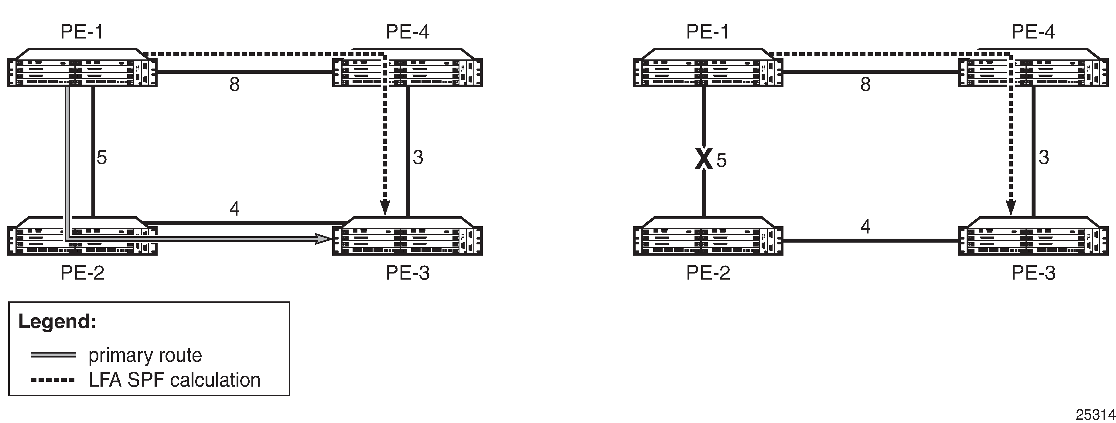
Selection Algorithm
For a point-to-point interface, if SPF finds multiple LFA next hops for a given primary next hop, the selection algorithm is as follows:
SPF will pick the node-protect type over the link-protect type.
If there is more than one LFA next hop within the selected type, it will pick one based on the least cost.
If there is more than one LFA next hop with the same cost, SPF will select the first one. This is not a deterministic selection and will vary for each SPF calculation.
For a broadcast interface, a node-protect LFA is not necessarily a link-protect LFA if the path to the LFA next hop goes over the same pseudonode as the primary next hop. Similarly, a link-protect LFA may not guarantee link protection if it goes over the same pseudonode as the primary next hop.
When SPF finds multiple LFA next hops for a given primary next hop, the selection algorithm is as follows:
The algorithm splits the LFA next hops into two sets:
the first set consists of LFA next hops that do not go over the pseudonode used by the primary next hop
the second set consists of LFA next hops that do go over the pseudonode used by the primary next hop
If there is more than one LFA next hop in the first set, it will pick the node-protect type over the link-protect type.
If there is more than one LFA next hop within the selected type, it will pick one based on the least cost.
If there is more than one LFA next hop with the same cost, SPF will select the first one from the remaining set. This is not a deterministic selection and will vary for each SPF calculation.
If no LFA next hop results from step 4, SPF will rerun steps 2 to 4 using the second set.
Both the calculated primary next hop and LFA next hop for a particular prefix are programmed into the RTM.
LFA Configuration
To enable LFA for IS-IS prefixes, enter the following command at the IS-IS instance level:
config>router>isis>loopfree-alternates
Next, enable FRR for LDP and/or IP by entering the following commands:
config>router>ldp>fast-reroute
config>router>ip-fast-reroute
These commands instruct the IS-IS SPF algorithm to precalculate a primary next hop and LFA next hop for every learned prefix, in order to provide FRR to LDP FEC packets and/or IP packets.
To exclude all interfaces within a specific IS-IS level or to exclude a specific IP interface from being included in the LFA SPF calculation, enter the following commands:
config>router>isis>level>loopfree-alternate-exclude
config>router>isis>interface>loopfree-alternate-exclude
If IGP shortcuts are also enabled, any LSPs with a destination address in that IS-IS level are not included in the LFA SPF calculation.
If an interface is excluded from the LFA SPF in IS-IS, it is excluded in both level 1 and level 2.
IGP Shortcuts (RSVP-TE Tunnels)
Micro-loops, especially in ring topologies, are typically unavoidable. As the number of nodes in a ring increases, the chance of micro-loops occurring also increases. In cases where a valid directly connected next hop cannot be ensured, remote LFAs can be used. Remote LFAs are non-directly connected LFA next hops that are reached via IGP shortcuts.
IGP shortcuts are an MPLS functionality where LSPs are treated like physical links within IGPs; that is, LSPs can be used for next-hop reachability. If an RSVP-TE LSP is used as a shortcut by OSPF or IS-IS, it is included in the SPF calculation as a point-to-point link for both primary and LFA next hops. It can also be advertised to neighbors so that the neighboring nodes can also use the links to reach a destination via the advertised next hop.
IGP shortcuts can be used to simplify remote LFA support and simplify the number of LSPs required in a ring topology.
IGP shortcut functionality provides two options:
LFA-protect option
This option allows an LSP to be included in both the main SPF and the Loop-Free Alternate (LFA) SPF algorithm. For a given prefix, the LSP can be used either as a primary next hop or as an LFA next hop, but not both. If the main SPF calculation selects a tunneled primary next hop for a prefix, the LFA SPF calculation will not select an LFA next hop for this prefix and the protection of this prefix will rely on the RSVP LSP FRR protection.
If the main SPF calculation selects a direct primary next hop, the LFA SPF calculation will select an LFA next hop for this prefix but will prefer a direct LFA next hop over a tunneled LFA next hop.
LFA-only option
This option allows an LSP to be included in the LFA SPF algorithm only, which means that the introduction of IGP shortcuts does not affect the main SPF decision. For a given prefix, the main SPF calculation always selects a direct primary next hop. The LFA SPF calculation will select an LFA next hop for this prefix but will prefer a direct LFA next hop over a tunneled LFA next hop.
Selection Algorithm
If there are multiple LFA next hops for a primary next hop, the selection algorithm is as follows:
The algorithm splits the LFA next hops into two sets:
the first set consists of direct LFA next hops
the second set consists of tunneled LFA next hops after excluding the LSPs that use the same outgoing interface as the primary next hop
The algorithm continues with the first set if it is not empty; otherwise, it continues with the second set.
If the second set is used, the algorithm selects the tunneled LFA next hop whose endpoint corresponds to the node advertising the prefix:
if more than one tunneled next hop exists, it selects the one with the lowest LSP metric
if more than one tunneled next hop still exists, it selects the one with the lowest tunnel ID
if none is available, it continues with rest of the tunneled LFAs in the second set
Within the selected set, the algorithm splits the LFA next hops into two sets:
the first set consists of LFA next hops that do not go over the pseudonode used by the primary next hop
the second set consists of LFA next hops that go over the pseudonode used by the primary next hop
If there is more than one LFA next hop in the selected set, it will pick the node-protect type over the link-protect type.
If there is more than one LFA next hop within the selected type, it will pick one based on the least total cost for the prefix. For a tunneled next hop, that means the LSP metric plus the cost of the LSP endpoint to the destination of the prefix.
If there is more than one LFA next hop within the selected type in the first set (ECMP is configured), it will select the first direct next hop from the remaining set. This is not a deterministic selection and will vary for each SPF calculation.
If there is more than one LFA next hop within the selected type in the second set (ECMP is configured), it will pick the tunneled next hop with the lowest cost from the endpoint of the LSP to the destination prefix. If there remains more than one next hop, it will pick the tunneled next hop with the lowest tunnel ID.
Forwarding Adjacency
The forwarding adjacency feature allows IS-IS to advertise an RSVP-TE LSP as a link so that other routers in the network can include it in the SPF calculations. The RSVP-TE is advertised as an unnumbered point-to-point link and the link-state PDU (LSP) has no traffic engineering opaque sub-TLVs as per RFC 3906, Calculating Interior Gateway Protocol (IGP) Routes Over Traffic Engineering Tunnels.
The forwarding adjacency feature can be enabled independently from the IGP shortcut feature. If both features are enabled for a given IS-IS instance, forwarding adjacency takes precedence.
When forwarding adjacency is enabled, each node advertises a point-to-point unnumbered link for each best-metric tunnel to the router ID of any endpoint node. The node does not include the tunnels as IGP shortcuts in the SPF calculation directly. Instead, when the LSP advertising the corresponding point-to-point unnumbered link is installed in the local routing database, the node performs an SPF calculation using the link like any other link LSP. The link bidirectional check requires that a regular link or tunnel link exist in the reverse direction for the tunnel to be used in SPF calculations.
IGP Shortcut Configuration
To enable the use of IGP shortcuts by IS-IS, enter the following command at the IS-IS instance level:
config>router>isis>rsvp-shortcut
To enable forwarding adjacency, enter the following command at the IS-IS instance level:
config>router>isis>advertise-tunnel-link
To enable the use of an RSVP-TE LSP by IS-IS as a shortcut or as a forwarding adjacency for resolving IGP routes, enter the following command:
config>router>mpls>lsp>igp-shortcut
When the rsvp-shortcut or advertise-tunnel-link option is enabled at the IS-IS instance level, all RSVP-TE LSPs originating on this node are eligible by default as long as the destination address of the LSP, as configured with the config>router> mpls>lsp>to command, corresponds to a router ID of a remote node. A specific LSP can be excluded from being used as a shortcut or forwarding adjacency with the no form of the igp-shortcut command.
LFA SPF Policies
An LFA SPF policy allows the user to apply specific criteria to the selection of an LFA backup next hop for a subset of prefixes that resolve to a specific primary next hop. The 7705 SAR supports the following LFA SPF policy constraints:
-
admin group
-
shared risk link group (SRLG)
-
protection type
-
next-hop type
A route next-hop policy template must first be created under the global router context. The template contains criteria for the policies in the preceding list.
The template is then applied to prefixes protected by LFA. Each instance of IS-IS can apply the same policy template to one or more prefixes and interfaces. If a template is modified, IS-IS re-evaluates it for any changes and, if necessary, schedules a new LFA SPF to recalculate the LFA next hop for any prefixes associated with the template.
As a related feature, prefixes that match a prefix entry in a prefix policy can be excluded from the LFA SPF calculation. If a prefix is excluded, it is not included in the LFA SPF calculation, regardless of its priority. Prefix policies are created with the config>router>policy-options>prefix-list command (for information about prefix lists, see the 7705 SAR Router Configuration Guide, ‟Route Policies”.
LFA SPF Policy Configuration
To create a route next-hop policy template, enter the following command:
config>router>route-next-hop-policy template
Configure the template with policy constraints for the items in the preceding list.
Next, apply the template to IS-IS interfaces by entering the following command:
config>router>isis>interface>lfa-policy-map>route-nh-template
The template is applied to all prefixes using the specified interface name.
Optionally, exclude prefixes in a prefix policy from the LFA SPF calculation by entering the following command:
config>router>isis>loopfree-alternates>exclude>prefix-policy
IS-IS Configuration Process Overview
IS-IS Configuration Process shows the process to provision basic IS-IS parameters.
Configuration Notes
General
IS-IS must be enabled on each participating 7705 SAR.
There are no default NETs.
There are no default interfaces.
By default, 7705 SAR routers are assigned a level 1/2 capability.
Configuring IS-IS with CLI
This section provides information to configure the Intermediate System-to-Intermediate System (IS-IS) protocol using the command line interface.
Topics in this section include:
IS-IS Configuration Overview
The 7705 SAR supports multi-instance IS-IS (MI-IS-IS). For IS-IS to operate on 7705 SAR routers, IS-IS must be explicitly enabled for each instance, and at least one area address and interface must be configured for the instance. If IS-IS is enabled but no area address or interface is configured, no routes are exchanged. When at least one area address and interface are configured, adjacencies can be formed and routes exchanged.
Basic IS-IS Configuration
The basic IS-IS configuration tasks that must be performed are:
enable IS-IS
modify the level capability on the global level from the default level 1/2 (if required)
define area addresses
configure IS-IS interfaces
The following output displays IS-IS default values:
Dut-B>config>router>isis# info detail
----------------------------------------------
            no router-id
            level-capability level-1/2
            no auth-keychain
            no authentication-key
            no authentication-type
            authentication-check
            csnp-authentication
            no ignore-lsp-errors
            lsp-lifetime 1200
            lsp-mtu-size 1492
            no database-export
            no overload
            no overload-on-boot
            no export
            hello-authentication
            psnp-authentication
            no traffic-engineering
            no reference-bandwidth
            no disable-ldp-sync
            no advertise-router-capability
            no rsvp-shortcut
            no advertise-tunnel-link
            no ignore-attached-bit
            no suppress-attached-bit
            no iid-tlv-enable
            no poi-tlv-enable
            no loopfree-alternates
            ipv4-routing
            no ipv6-routing
            no unicast-import-disable ipv4
            no multicast-import ipv4
            no strict-adjacency-check
            entropy-label
                override-tunnel-elc
            exit
            timers
                lsp-wait 5000 lsp-initial-wait 10 lsp-second-wait 1000
                spf-wait 10000 spf-initial-wait 1000 spf-second-wait 1000
            exit
            level 1
                advertise-router-capability
                no auth-keychain
                no authentication-key
                no authentication-type
                csnp-authentication
                no database-export-exclude
                external-preference 160
                hello-authentication
                no loopfree-alternate-exclude
                preference 15
                psnp-authentication
                no wide-metrics-only
            exit
            level 2
                advertise-router-capability
                no auth-keychain
                no authentication-key
                no authentication-type
                csnp-authentication
                no database-export-exclude
                external-preference 165
                hello-authentication
                no loopfree-alternate-exclude
                preference 18
                psnp-authentication
                no wide-metrics-only
            exit
            segment-routing
                shutdown
                adj-sid-hold 15
                entropy-label enable
                export-tunnel-table ldp
                no prefix-sid-range
                tunnel-table-pref 11
                no tunnel-mtu
                mapping-server
                    shutdown
                exit
            exit
            no shutdown
----------------------------------------------
Dut-B>config>router>isis#
Configuring IS-IS Components
The following sections show the CLI syntax for:
Enabling IS-IS
An IS-IS instance must be enabled in order for the protocol to be active. If the isis command is used without an isis-instance specified, the default (‟base”) instance is used.
To configure an IS-IS instance on a router, enter the following command:
- CLI Syntax:
configrouter router-nameisis [isis-instance]
Configuring an IS-IS Instance Level
When an IS-IS instance is enabled, the global default level capability is level 1/2. This means that the instance operates with both level 1 and level 2 routing capabilities. To change the default value in order for the instance to operate as a level 1 router or a level 2 router only, you must explicitly modify the level-capability value.
Select level-1 to route traffic only within an area. Select level-2 to route traffic to destinations outside an area, toward other eligible level 2 routers.
If the level-capability is modified, the protocol restarts, which will likely affect adjacencies and routes.
The level-capability value can be configured at the global level and on a per-interface level. The level-capability value determines which level values can be assigned on the router instance level or on an interface level.
The level command lets you configure parameters for level 1 or level 2 instances (or both).
To configure the router instance level, enter the following command:
- CLI Syntax:
config>router# isis [isis-instance]level-capability {level-1 | level-2 | level-1/2}level (1 | 2)
The following example displays a level configuration:
A:ALU-A>config>router>isis# info
----------------------------------------------
     level-capability level-1/2
     level 1
          no hello-authentication
          preference 150
     level 2
          preference 200
----------------------------------------------
A:ALU-A>config>router>isis#
If the default value is not modified on any routers in the area, the routers try to form both level 1 and level 2 adjacencies on all IS-IS interfaces. If the default values are modified to level 1 or level 2, the number of adjacencies formed are limited to that level only. See Interface Level Capability for information about the types of adjacencies that can be established depending on the global and interface level values.
Configuring ISO Area Addresses
The area-id command specifies the area address portion of the NET, which is used to define the IS-IS area to which the router will belong. At least one area ID must be configured per instance for each router participating in IS-IS; a maximum of three area IDs are supported. Use the following syntax to configure an ISO area address.
For more information about area addresses, see ISO Network Addressing.
- CLI Syntax:
config>router# isis [isis-instance]area-idarea-address
The following example shows the commands to configure the area ID.
- Example:
config>router>isis#config>router>isis# area-id 49.0180.0001config>router>isis# area-id 49.0180.0002config>router>isis# area-id 49.0180.0003
The following example displays an area ID configuration:
A:ALU-A>config>router>isis# info
----------------------------------------------
     area-id 49.0180.0001
     area-id 49.0180.0002
     area-id 49.0180.0003
----------------------------------------------
A:ALU-A>config>router>isis#
Configuring Global IS-IS Parameters
Commands and parameters configured on the global level are inherited by the interface levels. Parameters specified in the interface configuration override the global configuration for that interface.
Use the following syntax to configure global IS-IS parameters:
- CLI Syntax:
config>router# isis [isis-instance]level-capability {level-1 | level-2 | level-1/2}[no] authentication-checkauthentication-key {authentication-key|hash-key}[hash | hash2]authentication-type {password | message-digest}overload [timeoutseconds]traffic-engineering
The following example displays a global level configuration:
A:ALU-A>config>router>isis# info
----------------------------------------------
     level-capability level-2
     area-id 49.0180.0001
     area-id 49.0180.0002
     area-id 49.0180.0003
     authentication-key "H5vv6WrAAQU" hash
     authentication-type password
     overload timeout 90
     traffic-engineering
----------------------------------------------
A:ALU-A>config>router>isis#
Configuring Interface Parameters
By default, there are no interfaces associated with IS-IS. You must configure at least one IS-IS interface in order for IS-IS to work. An interface belongs to all areas configured on a router. Interfaces cannot belong to separate areas.
To enable IS-IS on an interface, first configure an IP interface in the config>router>interface context. Then, apply the interface in the config>router>isis>interface context.
The level-capability value can be configured on an interface. The default value is level 1/2. You can configure both level 1 parameters and level 2 parameters on an interface. The level-capability value determines which level values are used.
Use the following syntax to configure interface parameters:
- CLI Syntax:
config>router# isis [isis-instance]level {1 | 2}[no] wide-metrics-onlyinterface ip-int-namelevel-capability {level-1 | level-2 | level-1/2}mesh-group [value | blocked]interface-type {broadcast | point-to-point}
The following example displays a global level and interface configuration:
----------------------------------------------
A:ALU-A>config>router>isis# info
     level-capability level-2
     area-id 49.0180.0001
     area-id 49.0180.0002
     area-id 49.0180.0003
     authentication-key "H5vv6WrAAQU" hash
     authentication-type password
     traffic-engineering
     level 1
          wide-metrics-only
     exit
     level 2
          wide-metrics-only
     exit
     interface "system"
     exit
     interface "ALU-1-2"
          level-capability level-2
          mesh-group 85
     exit
     interface "ALU-1-3"
          level-capability level-1
          interface-type point-to-point
          mesh-group 101
     exit
     interface "ALU-1-5"
          level-capability level-1
          interface-type point-to-point
          mesh-group 85
     exit
     interface "to-103"
          mesh-group 101
     exit
----------------------------------------------
A:ALU-A>config>router>isis#
Example 1: Configuring a Level 1 Area
Interfaces are configured in the config>router>interface context. Configuring a Level 1 Area shows a level 1 area configuration.
The following example shows the commands to configure a level 1 area:
- Example:
A:ALU-A>config>router# isis..>isis# area-id 49.0180.0001..>isis# level-capability level-1..>isis# interface system..>isis>if# exit..>isis# interface ‟A-B”..>isis>if# exit..>isis# interface ‟A-C”..>isis>if# exit..>isis#A:ALU-B>config>router# isis..>isis# area-id 49.0180.0001..>isis# level-capability level-1..>isis# interface system..>isis>if# exit..>isis# interface ‟B-A”..>isis>if# exit..>isis# interface ‟B-C”..>isis>if# exit..>isis#A:ALU-C>config>router# isis..>isis# area-id 49.0180.0001..>isis# level-capability level-1..>isis# interface system..>isis>if# exit..>isis# interface "C-A"..>isis>if# exit..>isis# interface "C-B"..>isis>if# exit
The following example displays a level 1 area configuration:
A:ALU-A>config>router>isis# info
----------------------------------------------
     level-capability level-1
     area-id 49.0180.0001
     interface "system"
     exit
     interface "A-B"
     exit
     interface "A-C"
     exit
----------------------------------------------
A:ALU-A>config>router>isis#

A:ALU-B>config>router>isis# info
----------------------------------------------
     level-capability level-1
     area-id 49.0180.0001
     interface "system"
     exit
     interface "B-A"
     exit
     interface "B-C"
     exit
----------------------------------------------
A:ALU-B>config>router>isis#

A:ALU-C>config>router>isis# info
#------------------------------------------
echo "ISIS"
----------------------------------------------
     level-capability level-1
     area-id 49.0180.0001
     interface "system"
     exit
     interface "C-A"
     exit
     interface "C-B"
     exit
----------------------------------------------
A:ALU-C>config>router>isis#
Example 2: Modifying Router Level Capability
In the previous example, ALU-A, ALU-B, and ALU-C are configured as level 1 systems. Level 1 systems communicate with other level 1 systems in the same area. In this example, ALU-A is modified to set the level capability to level 1/2. Now the level 1 systems in the area with NET 49.0180.0001 forward PDUs to ALU-A for destinations that are not in the local area, as shown in Configuring a Level 1/2 Area.
The following example shows the commands to configure a level 1/2 area for ALU-A:
- Example:
A:ALU-A>config>router# isis..>isis# level-capability level-1/2
Interface Level Capability
The level capability value configured on the interface level is compared to the level capability value configured on the global level to determine the type of adjacencies that can be established. The default value for 7705 SAR routers and interfaces is level 1/2. Potential Adjacency Capabilities lists capability combinations and the potential adjacencies that can be formed.
Global Level |
Interface Level |
Potential Adjacency |
|---|---|---|
Level 1/2 |
Level 1/2 |
Level 1 and/or level 2 |
Level 1/2 |
Level 1 |
Level 1 only |
Level 1/2 |
Level 2 |
Level 2 only |
Level 2 |
Level 1/2 |
Level 2 only |
Level 2 |
Level 2 |
Level 2 only |
Level 2 |
Level 1 |
None |
Level 1 |
Level 1/2 |
Level 1 only |
Level 1 |
Level 2 |
None |
Level 1 |
Level 1 |
Level 1 only |
Configuring Authentication
Authentication must be explicitly configured and can be done using two separate mechanisms:
configuration of an explicit authentication key and algorithm using the authentication-key and authentication-type commands in the IS-IS global or IS-IS level contexts; configuration of a Hello PDU authentication key using the hello-authentication-key and hello-authentication-type commands in the IS-IS interface and IS-IS interface level contexts
configuration of an authentication keychain using the auth-keychain command in the config>system>security>keychain context and associating the keychain in the applicable IS-IS contexts
Either the authentication-key command or the auth-keychain command can be used by IS-IS, but both cannot be supported at the same time. If both commands are configured, the auth-keychain configuration will be applied and the authentication-key command will be ignored.
Use the following CLI syntax to configure authentication:
- CLI Syntax:
config>router# isis [isis-instance][no] authentication-checkauthentication-key {authentication-key | hash-key}[hash | hash2]authentication-type {password | message-digest}[no] hello-authenticationlevel {1 | 2}authentication-key {authentication-key | hash-key}[hash | hash2]authentication-type {password | message-digest}
- CLI Syntax:
config>router# isis [isis-instance]interface ip-int-name[no] hello-authenticationhello-authentication-key {authentication-key | hash-key}[hash | hash2]hello-authentication-type {password | message-digest}level {1 | 2}hello-authentication-key {authentication-key | hash-key}[hash | hash2]hello-authentication-type {password | message-digest}
Use the following CLI syntax to associate IS-IS at the global level or IS-IS level with an authentication keychain and to associate an IS-IS interface or interface level with a Hello authentication keychain. The keychain must already be defined in the system>security>keychain context.
- CLI Syntax:
config>router# isis [isis-instance]auth-keychain namelevel {1 | 2}auth-keychain name
- CLI Syntax:
config>router# isis [isis-instance]interface ip-int-namehello-auth-keychain namelevel {1 | 2}hello-auth-keychain name
Configuring Leaking
IS-IS allows a two-level hierarchy to route PDUs. Level 1 areas can be interconnected by a contiguous level 2 backbone.
The level 1 link-state database contains information only about that area. The level 2 link-state database contains information about the level 2 system and each of the level 1 systems in the area. A level 1/2 router contains information about both level 1 and level 2 databases. A level 1/2 router advertises information about its level 1 area toward the other level 1/2 or level 2 routers.
Packets with destinations outside the level 1 area are forwarded toward the closest level 1/2 router which, in turn, forwards the packets to the destination area.
Sometimes the shortest path to an outside destination is not through the closest level 1/2 router, or the only level 1/2 router to forward packets out of an area is not operational. Route leaking provides a mechanism to leak level 2 information to level 1 routers to provide routing information regarding inter-area routes. Route leaking therefore gives a level 1 router more options to forward packets.
Configure a route policy to leak routes from level 2 into level 1 areas in the config> router>policy-options>policy-statement context. For more information on creating route policies, see the 7705 SAR Router Configuration Guide.
The following example shows the commands to configure prefix list (‟loops”) and policy statement (‟leak”) parameters in the config>router context.
- Example:
config>router>policy-options# prefix-list loops..>policy-options>prefix-list# prefix 10.1.1.0/8 longer..>policy-options>prefix-list# exit..>policy-options# policy-statement leak..>policy-options>policy-statement# entry 10..>policy-options>policy-statement>entry# from..>policy-options>policy-statement>entry>from# prefix- list loops..>policy-options>policy-statement>entry>from# level 2..>policy-options>policy-statement>entry>from# exit..>policy-options>policy-statement>entry# to..>policy-options>policy-statement>entry>to# level 1..>policy-options>policy-statement>entry>to# exit..>policy-options>policy-statement>entry# action accept..>policy-options>policy-statement>entry>action# exit..>policy-options>policy-statement>entry# exit..>policy-options>policy-statement# exit..>policy-options# commit..>policy-options#
The following example displays a prefix list and policy statement configuration:
A:ALU-A>config>router>policy-options# info
----------------------------------------------
     prefix-list "loops"
          prefix 10.1.1.0/8 longer
     exit
     policy-statement "leak"
          entry 10
               from
                    prefix-list "loop"
                    level 2
               exit
               to
                    level 1
               exit
               action accept
               exit
          exit
     exit
----------------------------------------------
A:ALU-A>config>router>policy-options#
Next, apply the policy in order to leak routes from level 2 into level 1 routers on ALU-A:
- CLI Syntax:
config>router# isis [isis-instance]export leak
A:ALU-A>config>router>isis# info
----------------------------------------------
     area-id 49.0180.0001
     area-id 49.0180.0002
     area-id 49.0180.0003
     authentication-key "//oZrvL4FPn06nyRIJ5E" hash
     authentication-type password
     no authentication-check
     export "leak"
...
----------------------------------------------
A:ALU-A>config>router>isis#
Then, after the policy is applied, create a policy statement (‟isis-ext”) to redistribute external IS-IS routes from level 1 routers into the level 2 backbone (see Redistributing External IS-IS Routes). In the config>router context, configure the following policy statement parameters:
- Example:
config>router>policy-options# begin..>policy-options# policy-statement "isis-ext"..>policy-options>policy-statement# entry 10..>policy-options>policy-statement>entry$ from..>policy-options>policy-statement>entry>from$ external..>policy-options>policy-statement>entry>from# exit..>policy-options>policy-statement>entry# to..>policy-options>policy-statement>entry>to$ level 2..>policy-options>policy-statement>entry>to# exit..>policy-options>policy-statement>entry# action accept..>policy-options>policy-statement>entry>action# exit..>policy-options>policy-statement>entry# exit..>policy-options>policy-statement# exit..>policy-options# commit
Redistributing External IS-IS Routes
By default, IS-IS does not redistribute level 1 external routes into level 2. The policy to redistribute external IS-IS routes must be explicitly applied. Policies are created in the config>router>policy-options context. See the 7705 SAR Router Configuration Guide for information about creating policies.
The following example displays the policy statement configuration:
A:ALU-A>config>router>policy-options# info
----------------------------------------------
     prefix-list "loops"
          prefix 10.1.1.0/8 longer
     exit
     policy-statement "leak"
          entry 10
            from
                 prefix-list "loop"
                 level 2
            exit
            to
                 level 1
            exit
            action accept
            exit
          exit
     exit
     policy-statement "isis-ext"
          entry 10
            from
                 external
            exit
            to
                 level 2
            exit
            action accept
            exit
          exit
     exit
----------------------------------------------
A:ALU-A>config>router>policy-options#
Configuring IS-IS Support for LDP-to-SR Stitching
Configure the export-tunnel-table command using the following CLI syntax to support LDP-to-SR stitching.
- CLI Syntax:
config>router# isissegment-routingexport-tunnel-table ldp
The following example displays the LDP-to-SR stitching IS-IS configuration output.
A:NOK-1 Dut-A>config>router>isis# info detail
----------------------------------------------
            ....
            segment-routing
                ....
                export-tunnel-table ldp
                ....
                exit
            exit
            no shutdown
----------------------------------------------
A:NOK-1 Dut-A>config>router>isis#
Configuring an SR Mapping Server for IPv4 /32 Prefixes
Use the following CLI syntax to configure an SR mapping server for IPv4 /32 prefixes
- CLI Syntax:
config>router# isis [isis-instance]segment-routingmapping-serversid-map node-sid {index value [range value]} prefix {ip-address/mask | ip-address netmask} [set-flags {s}] [level {1 | 2 | 1/2}]
The following is an example of an SR mapping server configuration.
- Example:
config>router>isis 1config>router>isis$ segment-routingconfig>router>isis>segm-rtng$ mapping-serverconfig>router>isis>segm-rtng>map-serv$ sid-map node-sid index 10 range 10 prefix 10.10.10.10/32 set-flags s level 1config>router>isis>segm-rtng>map-serv$ exitconfig>router>isis>segm-rtng$ exitconfig>router>isis$ exit
The following example displays the SR mapping server configuration.
A:NOK-1 Dut-A>config>router>isis# info detail
----------------------------------------------
            ...
            segment-routing
                mapping-server
                    shutdown
                    sid-map node-sid index 10 range 10 prefix 10.10.10.10/32 set-
                    flags s level 1
                exit
            exit
            no shutdown
----------------------------------------------
A:NOK-1 Dut-A>config>router>isis#
IS-IS Configuration Management Tasks
This section discusses the following IS-IS configuration management tasks:
Disabling IS-IS
The shutdown command disables an IS-IS instance on the router. The configuration settings are not changed, reset, or removed.
Use the following CLI syntax to disable an IS-IS instance on a router:
- CLI Syntax:
config>router# isis [isis-instance]shutdown
Removing IS-IS
The no isis command deletes an IS-IS instance and reverts its configuration to default values for its next use.
Use the following CLI syntax to remove an IS-IS instance:
- CLI Syntax:
config>router#no isis [isis-instance]
Modifying Global IS-IS Parameters
You can modify, disable, or remove global IS-IS parameters without shutting down entities. The changes are applied immediately. Modifying the level capability on the global level causes the IS-IS instance to restart.
The following example displays an IS-IS global parameter modification.
- Example:
config>router>isis# overload timeout 500config>router>isis# level-capability level-1/2config>router>isis# no authentication-checkconfig>router>isis# authentication-key raider123
The following example displays the IS-IS configuration with the modifications entered in the previous example:
A:ALU-A>config>router>isis# info
----------------------------------------------
     area-id 49.0180.0001
     area-id 49.0180.0002
     area-id 49.0180.0003
     authentication-key "//oZrvtvFPn06nyRIJ5E" hash
     authentication-type password
     no authentication-check
     overload timeout 500
     level 1
          wide-metrics-only
     exit
     level 2
          wide-metrics-only
     exit
     interface "system"
     exit
     interface "ALU-1-2"
          level-capability level-2
          mesh-group 85
     exit
     interface "ALU-1-3"
          level-capability level-1
          interface-type point-to-point
          mesh-group 101
     exit
     interface "ALU-1-5"
          level-capability level-1
          interface-type point-to-point
          mesh-group 85
     exit
     interface "to-103"
          mesh-group 101
     exit
     interface "A-B"
     exit
     interface "A-C"
     exit
Modifying IS-IS Interface Parameters
You can modify, disable, or remove interface level IS-IS parameters without shutting down entities. Changes take effect immediately. Modifying the level capability on the interface causes the IS-IS instance on the interface to restart.
To remove an interface, use the no interface ip-int-name command.
To disable an interface, use the shutdown command in the interface context.
The following example displays an IS-IS interface parameter modification.
- Example:
config>router# isisconfig>router>isis# interface ALU-1-3config>router>isis>if# mesh-group 85config>router>isis>if# passiveconfig>router>isis>if# lsp-pacing-interval 5000config>router>isis>if# exitconfig>router>isis# interface to-103config>router>isis>if# hello-authentication-type message-digestconfig>router>isis>if# hello-authentication-key 49ersruleconfig>router>isis>if# exit
The following example displays the IS-IS configuration with the modifications entered in the previous example:
A:ALU-A>config>router>isis# info
----------------------------------------------
     area-id 49.0180.0001
     area-id 49.0180.0002
     area-id 49.0180.0003
     authentication-key "//oZrvtvFPn06nyRIJ5E" hash
     authentication-type password
     no authentication-check
     overload timeout 500
     level 1
          wide-metrics-only
     exit
     level 2
          wide-metrics-only
     exit
     interface "system"
     exit
     interface "ALU-1-2"
          level-capability level-2
          mesh-group 85
     exit
     interface "ALU-1-3"
          level-capability level-1
          interface-type point-to-point
          lsp-pacing-interval 5000
          mesh-group 85
          passive
     exit
     interface "ALU-1-5"
          level-capability level-1
          interface-type point-to-point
          mesh-group 85
     exit
     interface "to-103"
          hello-authentication-key "DvR5l2xxB6XMTvbAZ1mE" hash
          hello-authentication-type message-digest
          mesh-group 101
     exit
     interface "A-B"
     exit
----------------------------------------------
A:ALU-A>config>router>isis#
IS-IS Command Reference
Command Hierarchies
Tools Commands (see the Tools chapter in the 7705 SAR OAM and Diagnostics Guide)
Configuration Commands
config
    - router
        - [no] isis [isis-instance]
            - advertise-router-capability {area | as}
            - no advertise-router-capability
            - [no] advertise-tunnel-link
            - [no] area-id area-address
            - auth-keychain name
            - no auth-keychain
            - [no] authentication-check
            - authentication-key {authentication-key | hash-key} [hash | hash2]
            - no authentication-key
            - authentication-type {password | message-digest}
            - no authentication-type
            - [no] csnp-authentication
            - database-export [identifier id] [bgp-ls-identifier bgp-ls-id]
            - no database-export
            - [no] disable-ldp-sync
            - entropy-label
                - [no] override-tunnel-elc
            - export policy-name [policy-name...(up to 5 max)]
            - no export
            - [no] hello-authentication
            - [no] ignore-attached-bit
            - [no] ignore-lsp-errors
            - [no] iid-tlv-enable
            - [no] interface ip-int-name
                - [no] bfd-enable ipv4
                - csnp-interval seconds
                - no csnp-interval
                - hello-auth-keychain name
                - no hello-auth-keychain
                - [no] hello-authentication
                - hello-authentication-key {authentication-key | hash-key} [hash | hash2]
                - no hello-authentication-key
                - hello-authentication-type {password | message-digest}
                - no hello-authentication-type
                - interface-type {broadcast | point-to-point}
                - no interface-type
                - ipv4-node-sid index index_value
                - ipv4-node-sid label label_value
                - no ipv4-node-sid
                - ipv6-node-sid index index_value
                - ipv6-node-sid label label_value
                - no ipv6-node-sid
                - level {1 | 2}
                    - hello-auth-keychain name
                    - no hello-auth-keychain
                    - hello-authentication-key {authentication-key | hash-key} [hash | hash2]
                    - no hello-authentication-key
                    - hello-authentication-type {password | message-digest}
                    - no hello-authentication-type
                    - hello-interval seconds
                    - no hello-interval
                    - hello-multiplier multiplier
                    - no hello-multiplier
                    - metric metric
                    - no metric
                    - [no] passive
                    - priority number
                    - no priority
                - level-capability {level-1 | level-2 | level-1/2}
                - no level-capability
                - lfa-policy-map route-nh-template template-name
                - no lfa-policy-map
                - [no] loopfree-alternate-exclude
                - lsp-pacing-interval milliseconds
                - no lsp-pacing-interval
                - mesh-group [value | blocked]
                - no mesh-group
                - [no] passive
                - retransmit-interval seconds
                - no retransmit-interval
                - [no] sid-protection
                - [no] shutdown
            - [no] ipv4-routing
            - ipv6-routing native
            - no ipv6-routing
            - level {1 | 2}
                - auth-keychain name
                - no auth-keychain
                - authentication-key {authentication-key | hash-key} [hash | hash2]
                - no authentication-key
                - authentication-type {password | message-digest}
                - no authentication-type
                - [no] csnp-authentication
                - external-preference external-preference
                - no external-preference
                - [no] hello-authentication
                - [no] loopfree-alternate-exclude
                - preference preference
                - no preference
                - [no] psnp-authentication
                - [no] wide-metrics-only
            - level-capability {level-1 | level-2 | level-1/2}
            - no level-capability
            - [no] loopfree-alternates
                - exclude
                    - prefix-policy prefix-policy [prefix-policy...(up to 5 max)]
                    - no prefix-policy
                - remote-lfa [max-pq-cost value]
                - no remote-lfa
                    - node-protect [max-pq-nodes value]
                    - no node-protect
                - ti-lfa [max-sr-frr-labels value]
                - no ti-lfa
                    - [no] node-protect
            - lsp-lifetime seconds
            - no lsp-lifetime
            - lsp-mtu-size size
            - no lsp-mtu-size
            - [no] multicast-import [ipv4]
            - overload [timeout seconds]
            - no overload
            - overload-on-boot [timeout seconds]
            - no overload-on-boot
            - [no] poi-tlv-enable
            - [no] psnp-authentication
            - reference-bandwidth bandwidth-in-kbps
            - reference-bandwidth [tbps Tera-bps] [gbps Giga-bps] [mbps Mega-bps] [kbps Kilo-bps]
            - no reference-bandwidth
            - [no] rsvp-shortcut
            - [no] segment-routing
                - adj-sid-hold seconds
                - no adj-sid-hold
                - entropy-label {force-disable | enable}
                - no entropy-label
                - export-tunnel-table ldp
                - no export-tunnel-table
                - [no] mapping-server
                    - [no] shutdown
                    - sid-map node-sid {index value [range value]} prefix {ip address/mask} | ip-address netmask} [set-flags {s}] [level {1 | 2 | 1/2}]
                - prefix-sid-range global
                - prefix-sid-range start-label label-value max-index index-value
                - no prefix-sid-range
                - [no] shutdown
                - tunnel-mtu bytes
                - no tunnel-mtu
                - tunnel-table-pref preference
                - no tunnel-table-pref
            - [no] shutdown
            - [no] strict-adjacency-check
            - summary-address {ip-prefix/prefix-length | ip-prefix [netmask]} level
            - no summary-address {ip-prefix/prefix-length | ip-prefix [netmask]}
            - [no] suppress-attached-bit
            - [no] timers
                - lsp-wait lsp-wait [lsp-initial-wait initial-wait] [lsp-second-wait second-wait]
                - no lsp-wait
                - spf-wait spf-wait [spf-initial-wait initial-wait] [spf-second-wait second-wait]
                - no spf-wait
            - [no] traffic-engineering
            - [no] unicast-import-disable [ipv4]
Show Commands
show
    - router
        - isis all
        - isis [isis-instance]
            - adjacency [ip-int-name | ip-address | nbr-system-id] [detail]
            - capabilities [system-id | lsp-id] [level level]]
            - database [system-id | lsp-id] [detail] [level level]
            - hostname
            - interface [ip-int-name | ip-address] [detail]
            - lfa-coverage
            - mapping-server [prefix ip-address [/mask]] [index index] [level level] [flag {s}]
            - prefix-sids [ipv4-unicast | ipv6-unicast | mt mt-id-number] [ip-prefix[/prefix-length]] [sid sid] [adv-router {system-id | hostname}] [srms | no-srms]
            - routes [ipv4-unicast | ipv6-unicast | mt mt-id-number] [ip-prefix[/prefix-length]] [alternative] [exclude-shortcut] [detail]
            - spf-log [detail]
            - statistics
            - status
            - summary-address [ip-prefix[/prefix-length]]
            - topology [detail] [lfa]
Clear Commands
Monitor Commands
monitor
    - router
        - isis [isis-instance]
            - statistics [interval seconds] [repeat repeat] [absolute | rate]
Debug Commands
debug
    - router
        - isis [isis-instance]
            - [no] adjacency [ip-int-name | ip-address | nbr-system-id]
            - [no] cspf
            - interface [ip-int-name | ip-address]
            - no interface
            - leak [ip-address]
            - no leak
            - [no] lsdb [level-number] [system-id | lsp-id]
            - [no] misc
            - packet [packet-type] [ip-int-name | ip-address | ipv6-address] [detail]
            - no packet
            - rtm [ip-address]
            - no rtm
            - [no] spf [level-number] [system-id]
Command Descriptions
Configuration Commands
Generic Commands
shutdown
Syntax
[no] shutdown
Context
config>router>isis
config>router>isis>segment-routing
config>router>isis>segment-routing>mapping-server
config>router>isis>interface
Description
This command administratively disables the entity. When disabled, an entity does not change, reset, or remove any configuration settings or statistics. Many entities must be explicitly enabled using the no shutdown command.
The operational state of the entity is disabled as well as the operational state of any entities contained within. Many objects must be shut down before they can be deleted.
Unlike other commands and parameters where the default state is not indicated in the configuration file, shutdown and no shutdown are always indicated in system-generated configuration files.
The no form of the command puts an entity into the administratively enabled state.
Default
IS-IS Global - the IS-IS protocol is created in the no shutdown state
IS-IS Interface - when an IP interface is configured as an IS-IS interface, IS-IS on the interface is in the no shutdown state by default
Global Commands
isis
Syntax
[no] isis [isis-instance]
Context
config>router
Description
This command activates an IS-IS instance on the router and enables access to the context to define IS-IS parameters.
Instance 0, the base instance, is enabled when the isis command is run without specifying an isis-instance. Multiple IS-IS instances are enabled by including an isis-instance value.
The no form of the command deletes the IS-IS instance and removes all configuration parameters.
Default
no isis
Parameters
- isis-instance
the IS-IS instance ID. If no isis-instance is specified, instance 0 is used.
advertise-router-capability
Syntax
advertise-router-capability {area | as}
no advertise-router-capability
Context
config>router>isis
Description
This command enables advertisement of a router’s capabilities to its neighbors for informational and troubleshooting purposes. A TLV as defined in RFC 4971 advertises the TE Node Capability Descriptor capability.
The parameters (area and as) control the scope of the capability advertisements.
The no form of this command disables this capability.
Default
no advertise-router-capability
Parameters
- area
capabilities are only advertised within the area of origin
- as
capabilities are advertised throughout the entire autonomous system
advertise-tunnel-link
Syntax
[no] advertise-tunnel-link
Context
config>router>isis
Description
This command enables the forwarding adjacency feature. With this feature, IS-IS advertises an RSVP-TE LSP as a link so that other routers in the network can include it in their SPF calculations. The RSVP-TE LSP is advertised as an unnumbered point-to-point link and the link-state PDU (LSP) has no traffic engineering opaque sub-TLVs as per RFC 3906.
The forwarding adjacency feature can be enabled independently from the IGP shortcut feature (rsvp-shortcut). If both features are enabled for a given IS-IS instance, the forwarding adjacency feature takes precedence.
When this feature is enabled, each node advertises a point-to-point unnumbered link for each best-metric tunnel to the router ID of any endpoint node. The node does not include the tunnels as IGP shortcuts in the SPF calculation directly. Instead, when the LSP advertising the corresponding point-to-point unnumbered link is installed in the local routing database, the node performs an SPF calculation using the link like any other link LSP.
The link bidirectional check requires that a regular link or tunnel link exists in the reverse direction for the tunnel to be used in the SPF calculation.
An RSVP-TE LSP can be excluded from being used as a forwarding adjacency with the config>router>mpls>lsp>no igp-shortcut command.
The no form of this command disables forwarding adjacency and therefore disables the advertisement of RSVP-TE LSPs into IS-IS.
Default
no advertise-tunnel-link
area-id
Syntax
[no] area-id area-address
Context
config>router>isis
Description
This command configures the area ID portion of the Network Service Access Point (NSAP) address, which identifies a point of connection to the network, such as a router interface.
Addresses in the IS-IS protocol are based on the ISO NSAP addresses and Network Entity Titles (NETs), not IP addresses. NET addresses are constructed similarly to NSAPs with the exception that the selector ID is always 00. NET addresses are exchanged in Hello and LSP PDUs. All NET addresses configured on the node are advertised to its neighbors.
Up to three area addresses can be configured.
NSAP addresses are divided into three parts. Only the area ID portion is configurable:
area ID – a variable-length field between 1 and 13 bytes that identifies the area to which the router belongs. This field includes the Authority and Format Identifier (AFI) as the first (most significant) byte and the area identifier.
system ID – A 6-byte system identifier. This value is not configurable. The system ID is derived from the system or router ID and uniquely identifies the router.
selector ID – A 1-byte selector identifier that is always 00 for an NET. This value is not configurable.
For level 1 interfaces, neighbors can have different area IDs, but they must have at least one area ID (AFI + area) in common. Sharing a common area ID, they become neighbors and area merging between the potentially different areas can occur.
For level 2 interfaces, neighbors can have different area IDs. However, if they have no area IDs in common, they become only level 2 neighbors and only level 2 LSPs are exchanged.
For level 1/2 interfaces, neighbors can have different area IDs. If they have at least one area ID (AFI + area) in common, they become neighbors. In addition to exchanging level 2 LSPs, area merging between potentially different areas can occur.
If multiple area-id commands are entered, the system ID of all subsequent entries must match the system ID of the first area address.
The no form of the command removes the area address.
Default
n/a — no area address is assigned
Parameters
- area-address
the area ID, from 1 to 13 bytes (if fewer than 13 bytes are entered, the rest of the field is padded with zeros)
auth-keychain
Syntax
auth-keychain name
no auth-keychain
Context
config>router>isis
config>router>isis>level
Description
This command associates an authentication keychain with the IS-IS instance or level. The keychain is a collection of keys used to authenticate IS-IS messages from remote peers. The keychain allows the rollover of authentication keys during the lifetime of a session and also supports stronger authentication algorithms than clear text and MD5.
The keychain must already be defined in the config>system>security>keychain context.
Either the authentication-key command or the auth-keychain command can be used by IS-IS, but both cannot be supported at the same time. If both commands are configured, the auth-keychain configuration will be applied and the authentication-key command will be ignored.
By default, authentication is not enabled.
Default
no auth-keychain
Parameters
- name
the name of an existing keychain, up to 32 characters
authentication-check
Syntax
[no] authentication-check
Context
config>router>isis
Description
This command sets an authentication check to reject PDUs that do not match the type or key requirements.
The default behavior when authentication is configured is to reject all IS-IS protocol PDUs that have a mismatch in either the authentication type or authentication key.
When no authentication-check is configured, authentication PDUs are generated and IS-IS PDUs are authenticated on receipt. However, although mismatches cause an event to be generated, the mismatches will not be rejected.
Default
authentication-check
authentication-key
Syntax
authentication-key {authentication-key | hash-key} [hash | hash2]
no authentication-key
Context
config>router>isis
config>router>isis>level
Description
This command sets the authentication key used to verify PDUs sent by neighboring routers on the interface. Neighboring routers use passwords to authenticate PDUs sent from an interface. For authentication to work, both the authentication key and the authentication type on a segment must match. The authentication-type command must also be entered.
To configure authentication on the global level, configure this command in the config>router>isis context. When this parameter is configured on the global level, all PDUs are authenticated, including the Hello PDU.
To override the global setting for a specific level, configure the authentication-key command in the config>router>isis>level context. When configured within the specific level, Hello PDUs are not authenticated.
By default, no authentication key is configured.
Either the authentication-key command or the auth-keychain command can be used by IS-IS, but both cannot be supported at the same time. If both commands are configured, the auth-keychain configuration will be applied and the authentication-key command will be ignored.
The no form of the command removes the authentication key.
Default
no authentication-key
Parameters
- authentication-key
the authentication key can be any combination of ASCII characters up to 254 characters in length (unencrypted). If spaces are used in the string, the entire string must be enclosed in double quotes (‟ ”).
- hash-key
the hash key can be any combination of ASCII characters up to 352 characters in length (encrypted) or 407 characters in length (if the hash2 parameter is used). If spaces are used in the string, the entire string must be enclosed in double quotes (‟ ”).
This is useful when a user must configure the parameter, but for security purposes, the actual unencrypted key value is not provided.
- hash
specifies that the key is entered in an encrypted form. If the hash parameter is not used, the key is assumed to be in a non-encrypted, clear text form. For security, all keys are stored in encrypted form in the configuration file with the hash parameter specified.
- hash2
specifies that the key is entered in a more complex encrypted form. If the hash2 parameter is not used, the less encrypted hash form is assumed.
authentication-type
Syntax
authentication-type {password | message-digest}
no authentication-type
Context
config>router>isis
config>router>isis>level
Description
This command enables either simple password or message-digest authentication in the global IS-IS or IS-IS level context. Both the authentication key and the authentication type on a segment must match. The authentication-key command must also be entered.
Configure the authentication type at the global level in the config>router>isis context. Configure or override the global setting by configuring the authentication type in the config>router>isis>level context.
The no form of the command disables authentication.
Default
no authentication-type
Parameters
- password
enables simple password (plaintext) authentication. If authentication is enabled and no authentication type is specified in the command, simple password authentication is enabled.
- message-digest
enables message-digest MD5 authentication in accordance with RFC 1321. If this option is configured, at least one message-digest-key must be configured.
csnp-authentication
Syntax
[no] csnp-authentication
Context
config>router>isis
config>router>isis>level
Description
This command enables authentication of individual IS-IS packets of complete sequence number PDUs (CSNPs).
The no form of the command suppresses authentication of CSNP packets.
Default
csnp-authentication
database-export
Syntax
database-export [identifier id] [bgp-ls-identifier bgp-ls-id]
no database-export
Context
config>router>isis
Description
This command enables the population of the extended TE database (TE-DB) with the link-state information from the IS-IS instance.
The extended TE-DB is used as a central point for importing all link-state, link, node, and prefix information from IGP instances on the router and exporting the information to BGP-LS on the router. This information includes the IGP, TE, SID sub-TLV, and adjacency SID sub-TLV.
The no form of this command disables database exportation.
Default
no database-export
Parameters
- identifier
uniquely identifies the IGP instance in the BGP-LS NLRI when a router has interfaces participating in multiple IGP instances. This parameter defaults to the IGP instance ID assigned by the 7705 SAR. However, because the concept of instance ID defined in IS-IS (RFC 6822) is unique within a routing domain while the one specified for OSPF is significant for the local subnet only (RFC 6549), the user can remove any overlap by configuring the new identifier value to be unique within a particular IGP domain when this router sends the IGP link-state information using BGP-LS.
- id
specifies an entry ID to export
- bgp-ls-identifier
used with the Autonomous System Number (ASN) to correlate the BGP-LS NLRI advertisements of multiple BGP-LS speakers in the same IGP domain. If an NRC-P network domain has multiple IGP domains, BGP-LS speakers in each IGP domain must be configured with the same unique tuple {bgp-ls-identifier, asn}.
The BGP-LS identifier is optional and is only sent in a BGP-LS NLRI if configured in the IGP instance of an IGP domain.
If this IGP instance participates in traffic engineering with RSVP-TE or SR-TE, the traffic-engineering option is not strictly required because enabling the extended TE-DB populates this information automatically. However, it is recommended that the user enable traffic engineering to make the configuration consistent with other routers in the network that do not require enabling of the extended TE-DB.
- bgp-ls-id
specifies a BGP LS ID to export
disable-ldp-sync
Syntax
[no] disable-ldp-sync
Context
config>router>isis
Description
This command disables the IGP-LDP synchronization feature on all interfaces participating in the OSPF or IS-IS routing protocol. When this command is executed, the IGP immediately advertises the actual value of the link cost for all interfaces that have the IGP-LDP synchronization enabled if the currently advertised cost is different. IGP-LDP synchronization will then be disabled for all interfaces. This command does not delete the interface configuration.
The no form of this command restores the default settings and re-enables IGP-LDP synchronization on all interfaces participating in the OSPF or IS-IS routing protocol and for which the ldp-sync-timer is configured (see the 7705 SAR Router Configuration Guide for information about configuring the ldp-sync-timer).
Default
no disable-ldp-sync
entropy-label
Syntax
entropy-label
Context
config>router>isis
Description
This command enables the context for the configuration of entropy label capabilities (ELC) for the routing protocol.
override-tunnel-elc
Syntax
[no] override-tunnel-elc
Context
config>router>isis>entropy-label
Description
This command configures the ability to override any received entropy label capability advertisements. When enabled, the system assumes that all nodes for an IGP domain are capable of receiving and processing the entropy label on segment routed tunnels. This command can only be configured if entropy-label is enabled via the config>router>isis>segment-routing>entropy-label command.
The no version of this command disables the override. The system assumes entropy label capability for other nodes in the IGP instance if capability advertisements are received.
Default
no override-tunnel-elc
export
Syntax
export policy-name [policy-name…(up to 5 max)]
no export
Context
config>router>isis
Description
This command associates export route policies to determine which routes are exported from the route table to IS-IS.
If no export policy is specified, non-IS-IS routes are not exported from the routing table manager to IS-IS.
If multiple policy names are specified, the policies are evaluated in the order they are specified. The first policy that matches is applied. If multiple export commands are issued, the last command entered will override the previous command. A maximum of five policy names can be specified.
The no form of the command removes all policies from the configuration.
Refer to the 7705 SAR Router Configuration Guide for information on defining route policies.
Default
n/a — no export route policies specified
Parameters
- policy-name
the export route policy name. Allowed values are any string up to 32 characters long composed of printable, 7-bit ASCII characters. If the string contains special characters (such as #, $, or spaces), the entire string must be enclosed within double quotes.
The specified names must already be defined.
hello-authentication
Syntax
[no] hello-authentication
Context
config>router>isis
config>router>isis>interface
Description
This command enables authentication of individual IS-IS Hello PDUs.
The no form of the command suppresses authentication of Hello PDUs.
Default
hello-authentication
ignore-attached-bit
Syntax
[no] ignore-attached-bit
Context
config>router>isis
Description
This command specifies that this level 1 router will ignore the attached (ATT) bit in received level 1 link-state PDUs (LSPs) and therefore will not install the default route to the level 1/2 router that set the ATT bit.
The no form of the command specifies that the router will install the default route to the closest level 1/2 router.
Default
no ignore-attached-bit
ignore-lsp-errors
Syntax
[no] ignore-lsp-errors
Context
config>router>isis
Description
This command specifies that the router will ignore LSPs with internal checksum errors rather than purging the LSPs.
The no form of the command specifies that LSPs with internal checksum errors will be purged, which will cause the originator to resend the LSPs.
Default
no ignore-lsp-errors
iid-tlv-enable
Syntax
[no] iid-tlv-enable
Context
config>router>isis
Description
This command specifies whether the Instance Identifier (IID) TLV is enabled or disabled for this IS-IS instance so an interface can be used in multiple IS-IS instances.
When enabled, each IS-IS instance marks its packets with the IID TLV containing its unique 16-bit IID for the routing domain. You must use a shutdown/no shutdown command sequence on the IS-IS instance to make the change operational.
The no form of the command disables the IID TLV marking of packets.
Default
no iid-tlv-enable
ipv4-routing
Syntax
[no] ipv4-routing
Context
config>router>isis
Description
This command enables or disables IPv4 routing on the IS-IS instance.
Default
ipv4-routing
ipv6-routing
Syntax
ipv6-routing native
no ipv6-routing
Context
config>router>isis
Description
This command enables or disables single topology (native) IPv6 routing on the IS-IS instance. In native mode, IPv6 routing information is exchanged within IS-IS using IS-IS IPv6 TLVs.
Default
no ipv6-routing
Parameters
- native
specifies to use IS-IS IPv6 TLVs for IPv6 routing
level
Syntax
level {1 | 2}
Context
config>router>isis
config>router>isis>interface
Description
This command enables the context to configure IS-IS level 1 or level 2 area attributes.
To reset global and/or interface level parameters to the default, the following commands must be entered independently:
    - level> no hello-authentication-key
    - level> no hello-authentication-type
    - level> no hello-interval
    - level> no hello-multiplier
    - level> no metric
    - level> no passive
    - level> no priority
Default
level 1 or level 2
Special Cases
- Global IS-IS Level
the config>router>isis context configures default global parameters for both level 1 and level 2 interfaces
- IS-IS Interface Level
the config>router>isis>interface context configures IS-IS operational characteristics of the interfaces at level 1 and/or level 2. A logical interface can be configured on one level 1 and one level 2 interface. In this case, each level can be configured independently and parameters must be removed independently.
Parameters
- 1
specifies that the router or interface is a level 1 router or interface
- 2
specifies that the router or interface is a level 2 router or interface
external-preference
Syntax
external-preference external-preference
no external-preference
Context
config>router>isis>level
Description
This command configures the preference for IS-IS external routes for the IS-IS level. The preference for internal routes is set with the preference command.
The command configures the preference level for either level 1 or level 2 external routes. The default preferences are listed in Route Preference Defaults by Route Type.
A route can be learned by the router from different protocols, in which case, the costs are not comparable. When this occurs, the preference is used to decide which route will be used.
Different protocols should not be configured with the same preference. If this occurs, the tiebreaker is based on the default preferences as listed in Route Preference Defaults by Route Type.
Route Type |
Preference |
Configurable |
|---|---|---|
Direct attached |
0 |
No |
Static routes |
5 |
Yes |
OSPF internal |
10 |
Yes |
IS-IS level 1 internal |
15 |
Yes |
IS-IS level 2 internal |
18 |
Yes |
OSPF external |
150 |
Yes |
IS-IS level 1 external |
160 |
Yes |
IS-IS level 2 external |
165 |
Yes |
If multiple routes are learned with an identical preference using the same protocol, the lowest-cost route is used. If multiple routes are learned with an identical preference using the same protocol and the costs (metrics) are equal, the decision of which route to use is determined by the configuration of ECMP in the config>router context. See the 7705 SAR Router Configuration Guide for information about ECMP.
The no form of the command reverts to the default value.
Default
external-preference 160 — for IS-IS level 1 external routes
external-preference 165 — for IS-IS level 2 external routes
Parameters
- external-preference
the preference for external routes at this level, expressed as a decimal integer
loopfree-alternate-exclude
Syntax
[no] loopfree-alternate-exclude
Context
config>router>isis>level
config>router>isis>interface
Description
This command instructs IS-IS to exclude a specific interface or all interfaces participating in a specific IS-IS level from the LFA SPF calculation. The LFA SPF calculation can therefore be run only where it is needed.
If an interface is excluded from the LFA SPF in IS-IS, it is excluded in both level 1 and level 2.
Default
no loopfree-alternate-exclude
preference
Syntax
preference preference
no preference
Context
config>router>isis>level
Description
This command configures the preference for IS-IS level 1 or level 2 internal routes.
A route can be learned by the router from different protocols, in which case, the costs are not comparable. When this occurs, the preference is used to decide which route will be used.
Different protocols should not be configured with the same preference. If this occurs, the tiebreaker is based on the default preferences as listed in Route Preference Defaults by Route Type. If multiple routes are learned with an identical preference using the same protocol and the costs (metrics) are equal, the decision of which route to use is determined by the configuration of ECMP in the config>router context. See the 7705 SAR Router Configuration Guide for information about ECMP.
The no form of the command reverts to the default value.
Default
preference 15 — for IS-IS level 1 internal routes
preference 18 — for IS-IS level 2 internal routes
Parameters
- preference
the preference for internal routes expressed as a decimal integer
wide-metrics-only
Syntax
[no] wide-metrics-only
Context
config>router>isis>level
Description
This command enables the exclusive use of wide metrics in the LSPs for the level number. Narrow metrics can have values between 1 and 63. IS-IS can generate two TLVs, one for the adjacency and one for the IP prefix. In order to support traffic engineering, wider metrics are required. When wide metrics are used, a second pair of TLVs are added for the adjacency and the IP prefix.
By default, both sets of TLVs are generated. When wide-metrics-only is configured, IS-IS only generates the pair of TLVs with wide metrics for that level.
The no form of the command reverts to the default value.
Default
no wide-metrics-only
level-capability
Syntax
level-capability {level-1 | level-2 | level-1/2}
no level-capability
Context
config>router>isis
config>router>isis>interface
Description
This command configures the routing level for the IS-IS instance.
An IS-IS router and IS-IS interface can operate at level 1, level 2, or both level 1 and level 2.
A level 1 adjacency can be established if there is at least one area address shared by this router and a neighbor. A level 2 adjacency cannot be established over this interface.
A level 1/2 adjacency is created if the neighbor is also configured as a level 1/2 router and has at least one area address in common. A level 2 adjacency is established if there are no common area IDs.
A level 2 adjacency is established if another router is configured as a level 2 or level 1/2 router with interfaces configured as level 1/2 or level 2. Level 1 adjacencies will not established over this interface.
Potential Adjacency Capabilities lists capability combinations and the potential adjacencies that can be formed.
Global Level |
Interface Level |
Potential Adjacency |
|---|---|---|
Level 1/2 |
Level 1/2 |
Level 1 and/or level 2 |
Level 1/2 |
Level 1 |
Level 1 only |
Level 1/2 |
Level 2 |
Level 2 only |
Level 2 |
Level 1/2 |
Level 2 only |
Level 2 |
Level 2 |
Level 2 only |
Level 2 |
Level 1 |
None |
Level 1 |
Level 1/2 |
Level 1 only |
Level 1 |
Level 2 |
None |
Level 1 |
Level 1 |
Level 1 only |
The no form of the command removes the level capability from the configuration.
Default
level-1/2
Special Cases
- IS-IS Router
in the config>router>isis context, changing the level capability performs a restart on the IS-IS protocol instance
- IS-IS Interface
in the config>router>isis>interface context, changing the level capability performs a restart of IS-IS on the interface
Parameters
- level-1
specifies that the router or interface can operate at level 1 only
- level-2
specifies that the router or interface can operate at level 2 only
- level-1/2
specifies that the router or interface can operate at both level 1 and level 2
loopfree-alternates
Syntax
[no] loopfree-alternates
Context
config>router>isis
Description
This command enables loop-free alternate (LFA) computation by SPF for the IS-IS routing protocol.
When this command is enabled, it instructs the IGP SPF to attempt to precalculate both a primary next hop and an LFA backup next hop for every learned prefix. When found, the LFA next hop is populated in the routing table along with the primary next hop for the prefix.
The no form of this command disables LFA computation by the IGP SPF.
Default
no loopfree-alternates
exclude
Syntax
exclude
Context
config>router>isis>loopfree-alternates
Description
This command enables the context for identifying prefix policies to be excluded from the LFA calculation by IS-IS.
prefix-policy
Syntax
prefix-policy prefix-policy [prefix-policy...(up to 5 max)]
no prefix-policy
Context
config>router>isis>loopfree-alternates>exclude
Description
This command excludes from the LFA SPF calculation any prefixes that match a prefix entry or a tag entry in a prefix policy. If a prefix is excluded, it is not included in the LFA SPF calculation, regardless of its priority. The tag will, however, be used in the main SPF. Prefix policies are created with the command config>router>policy-options>prefix-list (for information about prefix lists, see the 7705 SAR Router Configuration Guide, ‟Route Policies”).
The default action of the loopfree-alternates>exclude>prefix-policy command, when not explicitly specified in the prefix policy, is to ‟reject”. Therefore, even if the default-action reject statement was not explicitly stated for the prefix policy, a prefix that does not match any entry in the policy will be used in the LFA SPF calculation.
The no form of the command deletes the excluded prefix policy.
Default
no prefix-policy
Parameters
- prefix-policy
the name of the prefix policy to be excluded from the LFA SPF calculation in this IS-IS instance. Up to five prefixes can be specified. The specified prefix policy must already be defined.
remote-lfa
Syntax
remote-lfa [max-pq-cost value]
no remote-lfa
Context
config>router>isis>loopfree-alternates
Description
This command enables the use of the remote LFA algorithm in the LFA SPF calculation in this IS-IS instance.
When this command is enabled in an IGP instance, SPF performs the additional remote LFA computation that follows the regular LFA next-hop calculation when the latter calculation results in no protection for one or more prefixes that are resolved to a particular interface.
Remote LFA extends the protection coverage of LFA-FRR to any topology by automatically computing and establishing or tearing down shortcut tunnels, also referred to as repair tunnels, to a remote LFA node that puts the packets back into the shortest path without looping them back to the node that forwarded them over the repair tunnel. The remote LFA node is referred to as a PQ node. A repair tunnel can, in theory, be an RSVP-TE LSP, an LDP-in-LDP tunnel, or a segment routing (SR) tunnel. The remote-lfa command is restricted to using an SR repair tunnel to the remote LFA node.
The remote LFA algorithm is a per-link LFA SPF calculation and not a per-prefix calculation like the regular LFA algorithm. The remote LFA algorithm provides protection for all destination prefixes that share the protected link by using the neighbor on the other side of the protected link as a proxy for all the destinations.
The no form of this command disables the use of the remote LFA algorithm in the LFA SPF calculation in this IS-IS instance.
Default
no remote-lfa
Parameters
- value
specifies the integer used to limit the search for candidate P and Q nodes in the remote LFA algorithm by setting the maximum IGP cost from the router performing the remote LFA calculation to the candidate P or Q node
node-protect
Syntax
node-protect [max-pq-nodes value]
no node-protect
Context
config>router>isis>loopfree-alternates>remote-lfa
config>router>isis>loopfree-alternates>ti-lfa
Description
This command administratively enables the use of the node-protect calculation in the remote LFA algorithm or topology-independent LFA (TI-LFA) algorithm in SPF computations. When node protection is enabled, the router prefers a node-protect repair tunnel over a link-protect repair tunnel for a particular prefix if both tunnels are found in the remote LFA or TI-LFA SPF computation. However, the SPF computations may only find a link-protect repair tunnel for prefixes owned by the protected node.
The max-pq-nodes parameter controls the maximum number of candidate PQ nodes found in the LFA SPFs for which the node protection check is performed. The node-protect condition means that the router must run the original link-protect remote LFA algorithm plus one extra forward SPF on behalf of each PQ node found, potentially after applying the max-pq-cost parameter, to verify that the path from the PQ node to the destination does not traverse the protected node. Setting the max-pq-nodes parameter to a lower value means that the LFA SPFs use less computation time and resources; however, this may result in not finding a node-protect repair tunnel.
The no form of the command disables the node-protect calculation.
Default
no node-protect
Parameters
- value
specifies the maximum number of PQ nodes found in the LFA SPFs for which the node protection check is performed
ti-lfa
Syntax
ti-lfa [max-sr-frr-labels value]
no ti-lfa
Context
config>router>isis>loopfree-alternates
Description
This command enables the use of the topology-independent LFA (TI-LFA) algorithm in the LFA SPF calculation in this IS-IS instance.
The TI-LFA algorithm improves the protection coverage of a network topology by computing and automatically instantiating a repair tunnel to a Q node that is not in the shortest path from the computing node. The repair tunnel uses the shortest path to the P node and a source-routed path from the P node to the Q node.
The TI-LFA repair tunnel can have a maximum of three labels pushed in addition to the label of the destination node or prefix. The user can set a lower maximum value for the additional FRR labels by configuring the max-sr-frr-labels option.
The no form of this command disables the use of the TI-LFA algorithm in the LFA SPF calculation in the IS-IS instance.
Default
no ti-lfa
Parameters
- value
specifies the maximum number of labels that the TI-LFA backup next hop can use. The TI-LFA algorithm uses this value to limit the search for the Q node from the P node on the post-convergence path.
lsp-lifetime
Syntax
lsp-lifetime seconds
no lsp-lifetime
Context
config>router>isis
Description
This command sets the time interval for LSPs originated by the router to be considered valid by other routers in the domain.
Each LSP received is maintained in an LSP database until the LSP lifetime expires, unless the originating router refreshes the LSP. Each router refreshes its LSPs at the half-life of the lsp-lifetime value (by default, every 10 min (600 s)), so that other routers will not age out the LSP.
The no form of the command reverts to the default value.
Default
1200
Parameters
- seconds
the interval for LSPs originated by the route to be considered valid by other routers in the domain
lsp-mtu-size
Syntax
lsp-mtu-size size
no lsp-mtu
Context
config>router>isis
Description
This command configures the LSP MTU size. If the MTU size is changed from the default value using the CLI or SNMP, IS-IS must be restarted in order for the change to take effect. This can be done by performing a shutdown command and then a no shutdown command in the config>router>isis context.
The no form of the command reverts to the default value.
Default
1492
Parameters
- size
the LSP MTU size
multicast-import
Syntax
[no] multicast-import [ipv4]
Context
config>router>isis
Description
This command enables the submission of routes into the multicast Route Table Manager (RTM) by IS-IS.
The no form of the command disables the submission of routes into the multicast RTM.
Default
no multicast-import ipv4
overload
Syntax
overload [timeout seconds]
no overload
Context
config>router>isis
Description
This command administratively sets the IS-IS router to operate in the overload state for a specific time period, in seconds, or indefinitely.
During normal operation, the router may be forced to enter an overload state due to a lack of resources. When in the overload state, the router is only used if the destination is reachable by the router and will not be used for other transit traffic.
If a time period is specified, the overload state persists for the configured length of time. If no time is specified, the overload state operation is maintained indefinitely.
The overload command can be useful in circumstances where the router is overloaded or used prior to executing a shutdown command to divert traffic around the router.
The no form of the command causes the router to exit the overload state.
Default
no overload
Parameters
- seconds
the number of seconds that the router remains in the overload state
overload-on-boot
Syntax
overload-on-boot [timeout seconds]
no overload-on-boot
Context
config>router>isis
Description
This command configures IS-IS in the overload state upon boot-up until one of the following events occurs:
the timeout timer expires
the current overload state is manually overridden with the no overload command
When the router is in an overload state, the router is used only if there is no other router to reach the destination.
The no overload command does not affect the overload-on-boot function. If the overload state is cleared with the no overload command, the router will still re-enter the overload state after rebooting.
If no timeout is specified, IS-IS will go into the overload state indefinitely after a reboot. After the reboot, the IS-IS status will display a permanent overload state:
L1 LSDB Overload : Manual on boot (Indefinitely in overload)
L2 LSDB Overload : Manual on boot (Indefinitely in overload)
This state can be cleared with the no overload command.
If a timeout value is specified, IS-IS will go into the overload state for the configured timeout after a reboot. After the reboot, the IS-IS status will display the remaining time that the system stays in overload:
L1 LSDB Overload : Manual on boot (Overload Time Left : 17)
L2 LSDB Overload : Manual on boot (Overload Time Left : 17)
The overload state can be cleared before the timeout expires with the no overload command.
The no form of the command removes the overload-on-boot functionality from the configuration.
Default
no overload-on-boot
Parameters
- seconds
the number of seconds that the router remains in the overload state after rebooting
poi-tlv-enable
Syntax
[no] poi-tlv-enable
Context
config>router>isis
Description
This command enables the use of the Purge Originator Identification (POI) TLV for this IS-IS instance. The POI is added to purges and contains the system ID of the router that generated the purge, which simplifies troubleshooting and determining what caused the purge. The no form of this command removes the POI functionality from the configuration.
Default
no poi-tlv-enable
psnp-authentication
Syntax
[no] psnp-authentication
Context
config>router>isis
config>router>isis>level
Description
This command enables authentication of individual IS-IS packets of partial sequence number PDUs (PSNPs).
The no form of the command suppresses authentication of PSNP packets.
Default
psnp-authentication
reference-bandwidth
Syntax
reference-bandwidth bandwidth-in-kbps
reference-bandwidth [tbps Tera-bps] [gbps Giga-bps] [mbps Mega-bps] [kbps Kilo-bps]
no reference-bandwidth
Context
config>router>isis
Description
This command configures the reference bandwidth used to calculate the default costs of interfaces based on their underlying link speed.
The default interface cost is calculated as follows:
cost = reference bandwidth/bandwidth
If the reference bandwidth is configured as 10 Gbytes (10 000 000 000), a 100 Mb/s interface has a default metric of 100. In order for metrics in excess of 63 to be configured, wide metrics must be deployed (see the wide-metrics-only command).
If the reference bandwidth is not configured, all interfaces have a default metric of 10.
The no form of the command resets the reference bandwidth to the default value.
Default
no reference-bandwidth (all interfaces have a metric of 10)
Parameters
- bandwidth-in-kbps
the reference bandwidth in kilobits per second, expressed as a decimal integer
- Tera-bps
the reference bandwidth in terabits per second, expressed as a decimal integer
- Giga-bps
the reference bandwidth in gigabits per second, expressed as a decimal integer
- Mega-bps
the reference bandwidth in megabits per second, expressed as a decimal integer
- Kilo-bps
the reference bandwidth in kilobits per second, expressed as a decimal integer
rsvp-shortcut
Syntax
rsvp-shortcut
no rsvp-shortcut
Context
config>router>isis
Description
This command enables the use of an RSVP-TE shortcut for resolving IS-IS routes. When the command is enabled, IS-IS includes RSVP-TE LSPs originating on this node and terminating on the router ID of a remote node as direct links with a metric equal to the operational metric provided by MPLS.
The SPF algorithm will always use the IGP metric to build the SPF tree, and the LSP metric value does not update the SPF tree calculation. During the IP reach to determine the reachability of nodes and prefixes, LSPs are overlaid and the LSP metric is used to determine the subset of paths that are of an equal lowest cost to reach a node or a prefix. If the relative-metric option for this LSP is enabled (in the config>router>mpls>lsp>igp-shortcut context), IS-IS will apply the shortest cost between the endpoints of the LSP plus the value of the offset, instead of the LSP operational metric, when calculating the cost of a prefix that is resolved to the LSP.
When a prefix is resolved to a tunnel next hop, the packet is sent labeled with the label stack corresponding to the NHLFE of the RSVP-TE LSP. Any network event that causes an RSVP-TE LSP to go down will trigger a full SPF calculation, which may result in a new route being installed over another RSVP-TE LSP shortcut as a tunnel next hop or over a regular IP next hop.
When the rsvp-shortcut command is enabled, all RSVP-TE LSPs originating on this node are eligible by default as long as the destination address of the LSP, as configured with the config>router>mpls> lsp>to command, corresponds to a router ID of a remote node. A specific LSP can be excluded from being used as a shortcut with the config>router>mpls> lsp>no igp-shortcut command.
If ECMP is enabled on the system and multiple equal-cost paths exist for the route over a set of tunnel next hops (based on the hashing routine supported for IPv4 packets), there are two possibilities:
if the destination is the tunnel endpoint, the system selects the tunnel with the lowest tunnel ID (the IP next hop is never used)
if the destination is different from the tunnel endpoint, the system:
selects tunnel endpoints where the LSP metric is lower than the IGP cost
prefers tunnel endpoints over IP next hops
ECMP is not performed across both the IP and tunnel next hops.
IS-IS can populate the multicast RTM with the prefix IP next hop when both rsvp-shortcut and multicast-import are enabled. The unicast RTM can still use the tunnel next hop for the same prefix.
The forwarding adjacency feature (advertise-tunnel-link) can be enabled independently from the shortcuts feature. If both features are enabled for a given IS-IS instance, the forwarding adjacency feature takes precedence.
The no form of this command disables the resolution of IGP routes using RSVP shortcuts.
Default
no rsvp-shortcut
segment-routing
Syntax
[no] segment-routing
Context
config>router>isis
Description
This command enables the context to configure segment routing parameters within an IGP instance.
Segment routing adds to IS-IS and OSPF routing protocols the ability to perform shortest path routing and source routing using the concept of abstract segment. An abstract segment can represent a local prefix of a node, a specific adjacency of the node (interface or next-hop), a service context, or a specific explicit path over the network. For each segment, the IGP advertises an identifier referred to as the segment ID (SID).
When segment routing is used together with the MPLS data plane, the SID is a standard MPLS label. A router forwarding a packet using segment routing will push one or more MPLS labels.
Segment routing using MPLS labels can be used in both shortest path routing applications and traffic engineering applications. On the 7705 SAR, segment routing implements the shortest path forwarding application.
After segment routing is successfully enabled in the IS-IS instance or in OSPF, the router will perform the following operations:
advertise the Segment Routing Capability sub-TLV to routers in all areas or levels of this IGP instance. However, only neighbors with which the IGP instance established an adjacency will interpret the SID and label range information and use it for calculating the label to swap to or push for a particular resolved prefix SID.
advertise the assigned index for each configured node SID in the new prefix SID sub-TLV with the N-flag (node SID flag) set. The segment routing module then programs the incoming label map (ILM) with a pop operation for each local node SID in the data path.
automatically assign and advertise an adjacency SID label for each formed adjacency over a network IP interface in the new Adjacency SID sub-TLV. The segment routing module programs the incoming label map (ILM) with a pop operation, in effect with a swap to an implicit null label operation, for each advertised adjacency SID.
resolve received prefixes, and if a prefix SID sub-TLV exists, the segment routing module programs the ILM with a swap operation and programs an LSP ID to NHLFE (LTN) with a push operation, both pointing to the primary/LFA NHLFE. An SR tunnel is also added to the TTM.
When the user enables segment routing in an IGP instance, the main SPF and LFA SPF are computed normally and the primary next hop and LFA backup next hop for a received prefix are added to the RTM without the label information advertised in the prefix SID sub-TLV.
adj-sid-hold
Syntax
adj-sid-hold seconds
no adj-sid-hold
Context
config>router>isis>segment-routing
Description
This command configures a timer to hold the ILM or LTN of an adjacency SID following a failure of the adjacency.
When an adjacency to a neighbor fails, the IGP will withdraw the advertisement of the link TLV information as well as its adjacency SID sub-TLV. However, the ILM or LTN record of the adjacency SID must be kept in the data path to maintain forwarding using the LFA or remote LFA backup for a sufficient length of time to allow the ingress LER and other routers that use this adjacency SID to activate a new path after the IGP converges.
If the adjacency is restored before the timer expires, the timer is aborted as soon as the new ILM or LTN records are updated with the new primary and backup NHLFE information.
The no form of the command removes the adjacency SID hold time.
Default
15
Parameters
- seconds
the adjacency SID hold time, in seconds
entropy-label
Syntax
entropy-label {force-disable | enable}
no entropy-label
Context
config>router>isis>segment-routing
Description
This command, when used with the force-disable keyword, instructs the system to ignore any received IGP advertisements of entropy label capability relating to remote nodes in the network. The command also prevents a user from configuring override-tunnel-elc for the IGP instance.
The no version of this command enables the processing of any received IGP advertisements of entropy label capability. Using the enable keyword has the same effect.
Default
entropy-label enable
Parameters
- force-disable
forces the system to ignore any received advertisements of entropy label capability signaled in the IGP
- enable
enables the system to process any received advertisements of entropy label capability signaled in the IGP
export-tunnel-table
Syntax
export-tunnel-table ldp
no export-tunnel-table
Context
config>router>isis>segment-routing
Description
This command enables the exporting of LDP tunnels from the TTM to an IGP instance for the purpose of stitching an SR tunnel to an LDP FEC for the same destination IPv4 /32 prefix.
When this command is enabled, the IGP monitors the LDP tunnel entries in the TTM. Whenever an LDP tunnel destination matches a prefix for which IGP received a prefix SID sub-TLV from the mapping server, the IGP instructs the SR module to program the SR ILM and to stitch it to the LDP tunnel endpoint.
The no form of this command disables the exporting of LDP tunnels to the IGP instance.
Default
no export-tunnel-table
Parameters
- ldp
exports LDP tunnels from the TTM to an IGP instance
mapping-server
Syntax
[no] mapping-server
Context
config>router>isis>segment-routing
Description
This command enables the context to enable the SR mapping server feature for an IS-IS instance.
The mapping server feature allows the configuration and advertisement via IS-IS of the node SID index for IS-IS prefixes of routers that are in the LDP domain. The router that is acting as a mapping server uses a prefix SID sub-TLV within the SID/Label Binding TLV in IS-IS to advertise a node SID index.
The no form of this command deletes the mapping server.
sid-map
Syntax
sid-map node-sid {index value [range value]} prefix {ip-address/mask | ip-address netmask} [set-flags {s}] [level {1 | 2 | 1/2}]
no sid-map node-sid index value
Context
config>router>isis>segment-routing>mapping-server
Description
This command configures the SR mapping server database for an IS-IS instance.
The node-sid index can be configured for one prefix or a range of prefixes by specifying the index value or a value range.
Only the first prefix in a consecutive range of prefixes must be entered. If the first prefix has a mask lower than 32, the SID/Label Binding TLV is advertised but the router does not resolve the prefix SIDs; a trap is originated instead.
The set-flags s option indicates to the IS-IS network routers that the flooding of the SID/Label Binding TLV applies to the entire domain. A router that receives the TLV advertisement leaks it between IS-IS levels 1 and 2. If leaked from level 2 to level 1, the D-flag must be set; this prevents the TLV from being leaked back into level 2. The S-flag is not defined by default; if it is not configured, the TLV is not leaked by routers receiving the mapping server advertisement.
The level option specifies the mapping server's flooding scope for the generated SID/Label Binding TLV using t. The default flooding scope of the mapping server is level 1/2.
The no form of this command deletes the range of node SIDs beginning with the specified index value.
Parameters
- index value
specifies the node SID index for the IS-IS prefix that will be advertised in a SID/Label Binding TLV
- range value
specifies the node SID range for the IS-IS prefixes that will be advertised in a SID/Label Binding TLV
- ip-address
specifies the IP address
- mask
specifies the subnet mask
- netmask
specifies the subnet mask in dotted-decimal notation
- set-flags s
specifies that the flooding of the SID/Label Binding TLV applies to the entire domain
- level {1 | 2 | 1/2}
specifies the mapping server flooding scope for the generated SID/Label Binding TLV
prefix-sid-range
Syntax
prefix-sid-range global
prefix-sid-range start-label label-value max-index index-value
no prefix-sid-range
Context
config>router>isis>segment-routing
Description
This command configures the prefix SID index range and offset label value for an IGP instance.
The key parameter is the configuration of the prefix SID index range and the offset label value that this IGP instance will use. Because each prefix SID represents a network global IP address, the SID index for a prefix must be unique network-wide. Therefore, all routers in the network are expected to configure and advertise the same prefix SID index range for an IGP instance. However, the label value used by each router to represent this prefix, that is, the label programmed in the ILM, can be local to that router by the use of an offset label, referred to as a start label:
Local Label (Prefix SID) = start-label + {SID index}
The label operation in the network is very similar to LDP when operating in the independent label distribution mode (RFC 5036, LDP Specification), with the difference that the label value used to forward a packet to each downstream router is computed by the upstream router based on the advertised prefix SID index using the above formula.
There are two mutually exclusive modes of operation for the prefix SID range on the router: global mode and per-instance mode.
In global mode, the user configures the global value and the IGP instance assumes that the start label value is the lowest label value in the Segment Routing Global Block (SRGB) and the prefix SID index range size is equal to the range size of the SRGB. When one IGP instance selects the global option for the prefix SID range, all IGP instances on the system must do the same. The user must shut down the segment routing context and disable the prefix-sid-range command in all IGP instances in order to change the SRGB. When the SRGB is changed, the user must re-enable the prefix-sid-range command. The SRGB range change will fail if an already allocated SID index/label goes out of range.
In per-instance mode, the user partitions the SRGB into non-overlapping sub-ranges among the IGP instances. The user configures a subset of the SRGB by specifying the start label value and the prefix SID index range size. All resulting net label values (start-label + index) must be within the SRGB or the configuration will fail. The 7705 SAR checks for overlaps of the resulting net label value range across IGP instances and will strictly enforce no overlapping of these ranges. The user must shut down the segment routing context of an IGP instance in order to change the SID index/label range of that IGP instance using the prefix-sid-range command. A range change will fail if an already allocated SID index/label goes out of range. The user can change the SRGB without shutting down the segment routing context as long as it does not reduce the current per-IGP instance SID index/label range defined with the prefix-sid-range command. Otherwise, the user must shut down the segment routing context of the IGP instance, and disable and re-enable the prefix-sid-range command.
Default
no prefix-sid-range
Parameters
- label-value
specifies the label offset for the SR label range of this IGP instance
- index-value
specifies the maximum value of the prefix SID index range for this IGP instance
tunnel-mtu
Syntax
tunnel-mtu bytes
no tunnel-mtu
Context
config>router>isis>segment-routing
Description
This command configures the MTU of all SR tunnels within each IGP instance.
The MTU of an SR tunnel populated into the TTM is determined in the same way as the MTU of an IGP tunnel (for example, an LDP LSP) based on the outgoing interface MTU minus the label stack size. Remote LFA can add, at most, one more label to the tunnel for a total of two labels. There is no default value for this command. If the user does not configure an SR tunnel MTU, the MTU, in bytes, is determined by IGP as follows:
SR_Tunnel_MTU = MIN {Cfg_SR_MTU, IGP_Tunnel_MTU – (1 + frr-overhead)✕ 4}
where:
Cfg_SR_MTU is the MTU configured by the user for all SR tunnels within an IGP instance using the tunnel-mtu command. If no value is configured by the user, the SR tunnel MTU is determined by the IGP interface calculation explained in the following bullet point
IGP_Tunnel_MTU is the minimum of the IS-IS or OSPF interface MTU among all the ECMP paths or among the primary and LFA backup paths of this SR tunnel
frr-overhead is set to 1 if the segment-routing and remote-lfa options are enabled in the IGMP instance. Otherwise, it is set to 0.
The SR tunnel MTU is dynamically updated whenever any of the above parameters used in its calculation changes. This includes if the set of the tunnel next hops changes or the user changes the configured SR MTU or interface MTU value.
Default
no tunnel-mtu
Parameters
- bytes
specifies the size of the MTU in bytes
tunnel-table-pref
Syntax
tunnel-table-pref preference
no tunnel-table-pref
Context
config>router>isis>segment-routing
Description
This command configures the TTM preference of shortest path SR tunnels created by the IGP instance. This is used for BGP shortcuts, VPRN auto-bind, or BGP transport tunnel when the tunnel binding commands are configured to the any value, which parses the TTM for tunnels in the protocol preference order. The user can choose either the global TTM preference or explicitly list the tunnel types they want to use. If the user lists the tunnel types explicitly, the TTM preference is still used to select one type over the other. In both cases, a fallback to the next preferred tunnel type is performed if the selected type fails. A reversion to a more preferred tunnel type is performed as soon as one is available.
The segment routing module adds to the TTM an SR tunnel entry for each resolved remote node SID prefix and programs the data path having the corresponding LTN with the push operation pointing to the primary and LFA backup NHLFEs.
The default preference for shortest path SR tunnels in the TTM is set lower than LDP tunnels but higher than BGP tunnels to allow controlled migration of customers without disrupting their current deployment when they enable segment routing. The following list shows the value of the default preference for the various tunnel types. This includes the preference of SR tunnels based on shortest path (referred to as SR-ISIS and SR-OSPF).
The global default TTM preference for the tunnel types is as follows:
ROUTE_PREF_RSVP 7
ROUTE_PREF_SR_TE 8
ROUTE_PREF_LDP 9
ROUTE_PREF_SR_OSPF_TTM 10
ROUTE_PREF_SR_ISIS_TTM 11
ROUTE_PREF_BGP_TTM 12
ROUTE_PREF_GRE 255
The default value for SR-ISIS is the same regardless of whether one or more IS-IS instances programmed a tunnel for the same prefix. The selection of an SR tunnel in this case is based on the lowest IGP instance ID.
Default
11
Parameters
- preference
specifies the integer value to represent the preference of IS-IS SR tunnels in the TTM
strict-adjacency-check
Syntax
[no] strict-adjacency-check
Context
config>router>isis
Description
This command enables strict checking of address families (IPv4 and IPv6) for IS-IS adjacencies. When enabled, adjacencies will not come up unless both routers have exactly the same address families configured. If there is an existing adjacency with unmatched address families, it will be torn down. By ensuring that adjacencies are only established if both routers have the same address families, this command prevents the blackholing of traffic that may occur when IPv4 and IPv6 topologies are different.
When the command is disabled, both routers only need to have one common address family to establish the adjacency. A BFD session failure for either IPv4 or IPv6 will cause the routes for the other address family to be removed as well.
Default
no strict-adjacency-check
summary-address
Syntax
summary-address {ip-prefix/prefix-length | ip-prefix [netmask]} level
no summary-address {ip-prefix/prefix-length | ip-prefix [netmask]}
Context
config>router>isis
Description
This command creates summary addresses.
Default
no summary-address
Parameters
- ip-prefix/prefix-length
IP prefix and mask length
- netmask
the subnet mask in dotted-decimal notation
- level
the IS-IS level
suppress-attached-bit
Syntax
[no] suppress-attached-bit
Context
config>router>isis
Description
This command suppresses the setting of the attached (ATT) bit in level 1 LSPs originated by this level 1/2 router to prevent all level 1 routers in the area from installing a default route to this router.
The no form of the command enables the setting of the ATT bit.
Default
no suppress-attached-bit
timers
Syntax
[no] timers
Context
config>router>isis
Description
This command configures the IS-IS timer values.
lsp-wait
Syntax
lsp-wait lsp-wait [lsp-initial-wait initial-wait] [lsp-second-wait second-wait]
no lsp-wait
Context
config>router>isis>timers
Description
This command is used to customize LSP generation throttling. Timers that determine when to generate the first, second, and subsequent LSPs can be controlled with this command. Subsequent LSPs are generated at increasing intervals of the second lsp-wait timer until a maximum value is reached.
Default
lsp-wait 5000
Parameters
- lsp-wait
the maximum interval, in milliseconds, between two consecutive occurrences of an LSP being generated
- initial-wait
the initial LSP generation delay, in milliseconds. Values less than 100 ms are internally rounded down to 0, so that there is no added initial LSP generation delay.
- second-wait
the hold time, in milliseconds, between the first and second LSP generation
spf-wait
Syntax
spf-wait spf-wait [spf-initial-wait initial-wait] [spf-second-wait second-wait]
no spf-wait
Context
config>router>isis>timers
Description
This command defines the maximum interval, in milliseconds, between two consecutive SPF calculations. Timers that determine when to initiate the first, second, and subsequent SPF calculations after a topology change occurs can be controlled with this command.
Subsequent SPF runs (if required) will occur at exponentially increasing intervals of the spf-second-wait interval. For example, if the spf-second-wait interval is 1000, the next SPF will run after 2000 ms, the SPF after that will run after 4000 ms, and so on, until it reaches the spf-wait value. The SPF interval will stay at the spf-wait value until there are no more SPF runs scheduled in that interval. After a full interval without any SPF runs, the SPF interval will drop back to the spf-initial-wait value.
Default
spf-wait 10000
Parameters
- spf-wait
the maximum interval, in milliseconds, between two consecutive SPF calculations
- initial-wait
the initial SPF calculation delay, in milliseconds, after a topology change
- second-wait
the hold time, in milliseconds, between the first and second SPF calculation
traffic-engineering
Syntax
[no] traffic-engineering
Context
config>router>isis
Description
This command enables traffic engineering and determines if IGP shortcuts are required.
The no form of the command disables traffic-engineered route calculations.
Default
no traffic-engineering
unicast-import-disable
Syntax
[no] unicast-import-disable [ipv4]
Context
config>router>isis
Description
This command allows one IGP to import its routes into the multicast RTM (also known as the RPF RTM [Reverse Path Forwarding - Route Table Manager]) while another IGP imports routes only into the unicast RTM. Import policies can redistribute routes from an IGP protocol into the RPF RTM. By default, the IGP routes will not be imported into the RPF RTM, since such an import policy must be explicitly configured.
The no form of the command enables importing IGP routes into the RPF RTM.
Default
no unicast-import-disable ipv4
Interface Commands
interface
Syntax
[no] interface ip-int-name
Context
config>router>isis
Description
This command enables the context to configure an IS-IS interface.
When an area is defined, the interfaces belong to that area. Interfaces cannot belong to other areas.
If the interface is a POS channel, the OSI Network Layer Control Protocol (OSINLCP) is enabled when the interface is created and removed when the interface is deleted.
The no form of the command deletes the IS-IS interface configuration for this interface. The shutdown command in the config>router>isis>interface context can be used to disable an interface without removing the configuration for the interface.
Default
no interface
Parameters
- ip-int-name
the IP interface name. Interface names must be unique within the group of defined IP interfaces for the config>router>interface command. An interface name cannot be in the form of an IP address. Interface names can be any string up to 32 characters long composed of printable, 7-bit ASCII characters. If the string contains special characters (such as #, $, or spaces), the entire string must be enclosed within double quotes.
bfd-enable
Syntax
[no] bfd-enable ipv4
Context
config>router>isis>interface
Description
This command enables the use of bidirectional forwarding (BFD) to control IPv4 adjacencies. By enabling BFD on a given IS-IS interface, the state of the interface is tied to the state of the BFD session between the local node and the remote node. The parameters used for BFD are set via the BFD command under the IP interface.
The no form of this command removes BFD from the associated IPv4 adjacency.
Default
no bfd-enable ipv4
csnp-interval
Syntax
csnp-interval seconds
no csnp-interval
Context
config>router>isis>interface
Description
This command configures the interval, in seconds, to send complete sequence number PDUs (CSNPs) from the interface. IS-IS must send CSNPs periodically.
The no form of the command reverts to the default value.
Default
csnp-interval 10 – CSN PDUs are sent every 10 s for LAN interfaces
csnp-interval 5 – CSN PDUs are sent every 5 s for point-to-point interfaces
Parameters
- seconds
the CSNP interval expressed in seconds
hello-auth-keychain
Syntax
hello-auth-keychain name
no hello-auth-keychain
Context
config>router>isis>interface
config>router>isis>interface>level
Description
This command associates a Hello authentication keychain with the IS-IS interface or interface level. The keychain is a collection of keys used to authenticate IS-IS messages from remote peers. The keychain allows the rollover of authentication keys during the lifetime of a session and also supports stronger authentication algorithms than clear text and MD5.
The keychain must already be defined in the config>system>security>keychain context.
Either the hello-authentication-key command or the hello-auth-keychain command can be used by IS-IS, but both cannot be supported at the same time. If both commands are configured, the hello-auth-keychain configuration will be applied and the hello-authentication-key command will be ignored.
Default
no hello-auth-keychain
Parameters
- name
the name of the keychain, up to 32 characters
hello-authentication-key
Syntax
hello-authentication-key {authentication-key | hash-key} [hash | hash2]
no hello-authentication-key
Context
config>router>isis>interface
config>router>isis>interface>level
Description
This command configures the authentication key (password) for Hello PDUs. Neighboring routers use the password to verify the authenticity of Hello PDUs sent from this interface. Both the Hello authentication key and the Hello authentication type on a segment must match. The hello-authentication-type command must also be entered.
To configure the Hello authentication key for all levels configured for the interface, use the hello-authentication-key command in the config>router>isis>interface context.
To configure or override the Hello authentication key for a specific level, use the hello-authentication-key command in the config>router>isis>interface>level context.
If both IS-IS authentication and Hello authentication are configured, Hello messages are validated using Hello authentication. If only IS-IS authentication is configured, it will be used to authenticate all IS-IS protocol PDUs, including Hello PDUs.
Either the hello-authentication-key command or the hello-auth-keychain command can be used by IS-IS, but both cannot be supported at the same time. If both commands are configured, the hello-auth-keychain configuration will be applied and the hello-authentication-key command will be ignored.
The no form of the command removes the hello authentication key from the configuration.
Default
no hello-authentication-key
Parameters
- authentication-key
the authentication key can be any combination of ASCII characters up to 254 characters in length (unencrypted). If spaces are used in the string, the entire string must be enclosed within double quotes (‟ ”).
- hash-key
the hash key can be any combination of ASCII characters up to 352 characters in length (encrypted) or 451 characters in length (if the hash2 parameter is used). If spaces are used in the string, the entire string must be enclosed within double quotes (‟ ”).
This is useful when a user must configure the parameter, but for security purposes, the actual unencrypted key value is not provided.
- hash
specifies that the key is entered in an encrypted form. If the hash parameter is not used, the key is assumed to be in a non-encrypted, clear text form. For security, all keys are stored in encrypted form in the configuration file with the hash parameter specified.
- hash2
specifies that the key is entered in a more complex encrypted form. If the hash2 parameter is not used, the less encrypted hash form is assumed.
hello-authentication-type
Syntax
hello-authentication-type {password | message-digest}
no hello-authentication-type
Context
config>router>isis>interface
config>router>isis>interface>level
Description
This command enables Hello authentication at either the interface or level context. Both the hello authentication key and the hello authentication type on a segment must match. The hello-auth-keychain command must also be entered.
To configure the hello authentication type for all levels configured for the interface, use the hello-authentication-type command in the config>router>isis>interface context.
To configure or override the hello authentication type for a specific level, use the hello-authentication-type command in the config>router>isis>interface>level context.
The no form of the command disables Hello PDU authentication.
Default
no hello-authentication-type
Parameters
- password
enables simple password (plaintext) authentication. If authentication is enabled and no authentication type is specified in the command, simple password authentication is enabled.
- message-digest
enables message-digest MD5 authentication in accordance with RFC 1321. If this option is configured, at least one message-digest-key must be configured.
hello-interval
Syntax
hello-interval seconds
no hello-interval
Context
config>router>isis>interface>level
Description
This command configures the interval between IS-IS Hello PDUs issued on the interface at this level. The hello-interval, along with the hello-multiplier, is used to calculate a hold time, which is communicated to a neighbor in a Hello PDU.
The no form of this command reverts to the default value.
Default
3 – for designated intermediate system interfaces
9 – for non-designated intermediate system interfaces and point-to-point interfaces
Parameters
- seconds
the hello interval, in seconds, expressed as a decimal integer
hello-multiplier
Syntax
hello-multiplier multiplier
no hello-multiplier
Context
config>router>isis>interface>level
Description
This command configures a hello multiplier. The hello-multiplier, along with the hello-interval, is used to calculate a hold time, which is communicated to a neighbor in a Hello PDU.
The hold time is the time in which the neighbor expects to receive the next Hello PDU. If the neighbor receives a Hello within this time, the hold time is reset. If the neighbor does not receive a Hello within the hold time, it brings the adjacency down.
The no form of this command reverts to the default value.
Default
3
Parameters
- multiplier
the multiplier for the hello interval, in seconds, expressed as a decimal integer
interface-type
Syntax
interface-type {broadcast | point-to-point}
no interface-type
Context
config>router>isis>interface
Description
This command configures the interface type to be either broadcast or point-to-point.
Use this command to set the interface type of an Ethernet link to point-to-point to avoid having to carry the broadcast adjacency maintenance overhead of the Ethernet link, provided the link is used as a point-to-point link.
If the interface type is not known when the interface is added to IS-IS, and the IP interface is subsequently bound (or moved) to a different interface type, this command must be entered manually.
The no form of the command reverts to the default value.
Default
broadcast – if the physical interface is Ethernet or unknown
point-to-point – if the physical interface is T1, E1, or SONET/SDH
Parameters
- broadcast
configures the interface to maintain this link as a broadcast network. To significantly improve adjacency forming and network convergence, a network should be configured as point-to-point if only two routers are connected, even if the network is a broadcast media such as Ethernet.
- point-to-point
configures the interface to maintain this link as a point-to-point link
ipv4-node-sid
Syntax
ipv4-node-sid index index-value
ipv4-node-sid label label-value
no ipv4-node-sid
Context
config>router>isis>interface
Description
This command assigns a node SID index or label value to the prefix representing the primary address of an IPv4 network interface of type loopback. Only a single node SID can be assigned to an interface. The secondary address of an IPv4 interface cannot be assigned a node SID index and does not inherit the SID of the primary IPv4 address.
This command fails if the network interface is not of type loopback or if the interface is defined in an IES or a VPRN context.
Assigning the same SID index or label value to the same interface in two different IGP instances is not allowed within the same node.
The value of the label or index SID is taken from the range configured for this IGP instance. When using the global mode of operation, the segment routing module checks that the same index or label value is not assigned to more than one loopback interface address. When using the per-instance mode of operation, this check is not required because the index, and therefore the label ranges, of IGP instances are not allowed to overlap.
Default
no ipv4-node-sid
Parameters
- index-value
specifies the index value
- label-value
specifies the label value
ipv6-node-sid
Syntax
ipv6-node-sid index index-value
ipv6-node-sid label label-value
no ipv6-node-sid
Context
config>router>isis>interface
Description
This command assigns a node SID index or label value to the prefix representing the primary address of an IPv6 network interface of type loopback. Only a single node SID can be assigned to an IPv6 interface. When an IPv6 interface has multiple global addresses, the primary address is always the first one in the list, as displayed by the interface info command.
This command fails if the network interface is not of type loopback or if the interface is defined in an IES or a VPRN context.
Assigning the same SID index or label value to the same interface in two different IGP instances is not allowed within the same node.
The value of the label or index SID is taken from the range configured for this IGP instance. When using the global mode of operation, the segment routing module checks that the same index or label value is not assigned to more than one loopback interface address. When using the per-instance mode of operation, this check is not required because the index, and therefore the label ranges, of IGP instances are not allowed to overlap.
Default
no ipv6-node-sid
Parameters
- index-value
specifies the index value
- label-value
specifies the label value
lfa-policy-map
Syntax
lfa-policy-map route-nh-template template-name
no lfa-policy-map
Context
config>router>isis>interface
Description
This command applies a route next-hop policy template to an IS-IS interface. When a route next-hop policy template is applied to an interface in IS-IS, it is applied in both level 1 and level 2.
If the interface has been excluded from LFA with the loopfree-alternate-exclude command, the LFA policy has no effect on the interface.
If the route next-hop policy template is applied to a loopback interface or to the system interface, the command will not be rejected, but the policy will have no effect on the interface.
The no form of the command deletes the mapping of a route next-hop policy template to an IS-IS interface.
Default
no lfa-policy-map
Parameters
- template-name
the name of an existing template
lsp-pacing-interval
Syntax
lsp-pacing-interval milliseconds
no lsp-pacing-interval
Context
config>router>isis>interface
Description
This command configures the interval between link-state PDUs (LSPs) sent from this interface. Controlling the time between LSPs ensures that adjacent neighbors are not being bombarded with excessive data.
A value of 0 means that no LSPs are sent from the interface.
The no form of the command reverts to the default value.
Default
100
Parameters
- milliseconds
the interval that LSPs can be sent from the interface, expressed as a decimal integer
mesh-group
Syntax
mesh-group [value | blocked]
no mesh-group
Context
config>router>isis>interface
Description
This command assigns an interface to a mesh group. Mesh groups limit the amount of flooding that occurs when a new or changed LSP is advertised throughout an area.
All routers in a mesh group should be fully meshed. When LSPs need to be flooded, only a single copy is received rather than one copy per neighbor.
To create a mesh group, configure the same mesh group value for each interface that is part of the mesh group. All routers must have the same mesh group value configured for all interfaces that are part of the mesh group.
To prevent an interface from flooding LSPs, the optional blocked parameter can be specified.
The no form of the command removes the interface from the mesh group.
Default
no mesh-group
Parameters
- value
the unique decimal integer that distinguishes this mesh group from other mesh groups on this router or on other routers
- blocked
prevents an interface from flooding LSPs
metric
Syntax
metric metric
no metric
Context
config>router>isis>interface>level
Description
This command configures the metric used for the level on this IS-IS interface.
To calculate the lowest cost to reach a given destination, each configured level on each interface must have a cost. The costs for each level on an interface may be different.
If the metric is not configured, the default value of 10 is used unless the reference-bandwidth is configured.
The no form of the command reverts to the default value.
Default
no metric (10)
Parameters
- metric
the metric assigned to this level on this interface, expressed as a decimal integer
passive
Syntax
[no] passive
Context
config>router>isis>interface
config>router>isis>interface>level
Description
This command adds the passive attribute to the IS-IS interface, which causes the interface to be advertised as an IS-IS interface without running the IS-IS protocol. Normally, only interface addresses that are configured for IS-IS are advertised as IS-IS interfaces at the level that they are configured.
If the passive mode is enabled, the interface or the interface at the specified level ignores ingress IS-IS protocol PDUs and will not transmit IS-IS protocol PDUs.
The no form of the command removes the passive attribute.
Default
no passive
priority
Syntax
priority number
no priority
Context
config>router>isis>interface>level
Description
This command configures the priority of the IS-IS interface that is used in an election of the designated router (DIS) on a multi-access network.
This parameter is only used if the interface is a broadcast type.
The priority is included in Hello PDUs transmitted by the interface on a multi-access network. The router with the highest priority becomes the designated router. The designated router is responsible for sending LSPs about the network and the routers attached to it.
The no form of the command reverts to the default value.
Default
64
Parameters
- number
the priority for this interface at this level, expressed as a decimal integer
retransmit-interval
Syntax
retransmit-interval seconds
no retransmit-interval
Context
config>router>isis>interface
Description
This command specifies the interval, in seconds, that IS-IS will wait before retransmitting an unacknowledged LSP to an IS-IS neighbor.
If the retransmit interval expires and no acknowledgment has been received, the LSP will be retransmitted.
The no form of this command reverts to the default interval.
Default
5
Parameters
- seconds
the retransmit interval, in seconds, expressed as a decimal integer
sid-protection
Syntax
[no] sid-protection
Context
config>router>isis>interface
Description
This command enables or disables adjacency SID protection by LFA and remote LFA.
LFA and remote LFA Fast Reroute (FRR) protection is enabled for all node SIDs and local adjacency SIDs when the user enables the loopfree-alternate option in IS-IS or OSPF at the LER and LSR. However, there may be applications where the user never wants traffic to divert from the strict hop computed by CSPF for an SR-TE LSP. In this case, the user can disable protection for all adjacency SIDs formed over a particular network IP interface using this command.
The protection state of an adjacency SID is advertised in the B flag of the IS-IS or OSPF Adjacency SID sub-TLV.
Default
sid-protection
Show Commands
isis
Syntax
isis all
isis [isis-instance]
Context
show>router
Description
This command enables the context to display IS-IS information.
Parameters
- all
enables the context to display all IS-IS instances
- isis-instance
enables the context to display the specified IS-IS instance ID. If no isis-instance is specified, instance 0 is used.
adjacency
Syntax
adjacency [ip-int-name | ip-address | nbr-system-id] [detail]
Context
show>router>isis
Description
This command displays information about IS-IS neighbors. If no parameters are specified, adjacencies for the specified IS-IS instance are displayed. If detail is specified, operational and statistical information is displayed.
To display adjacency information for all IS-IS instances, use the show router isis all context.
Parameters
- ip-int-name
displays only adjacencies with the specified interface
- ip-address
displays only adjacencies with the specified IP address
- nbr-system-id
displays only the adjacency with the specified system ID
- detail
displays detailed information about the adjacency
Output
The following output is an example of IS-IS adjacency information, and Adjacency Field Descriptions describes the fields for both summary and detailed outputs.
Output ExampleA:ALU-A# show router isis adjacency
===============================================================================
Rtr Base ISIS Instance 0 Adjacency
===============================================================================
System ID Usage State Hold Interface MT-ID
-------------------------------------------------------------------------------
ALU-B L1 Up 2 ip-to1 0
ALU-B L2 Up 2 ip-to2 0
ALU-F L1L2 Up 5 ip-303 0
-------------------------------------------------------------------------------
Adjacencies : 3
===============================================================================
A:ALU-A#
*A:Sar18 Dut-B>show>router# isis all adjacency
===============================================================================
Rtr Base ISIS Instance 0 Adjacency
===============================================================================
System ID            Usage State Hold Interface                MT-ID
-------------------------------------------------------------------------------
ALU-B                L1    Up    2    ip-to1                   0
ALU-B                L2    Up    2    ip-to2                   0
ALU-F                L1L2  Up    5    ip-303                   0
===============================================================================
===============================================================================
Rtr Base ISIS Instance 1 Adjacency
===============================================================================
System ID                Usage State Hold Interface            MT-ID
-------------------------------------------------------------------------------
No Matching Entries
===============================================================================
===============================================================================
Rtr Base ISIS Instance 2 Adjacency
===============================================================================
System ID                Usage State Hold Interface            MT-ID
-------------------------------------------------------------------------------
No Matching Entries
===============================================================================
Label |
Description |
|---|---|
System ID |
System ID of the neighbor |
Usage/L. Circ Typ |
Level on the interface: L1, L2, or L1/2 |
State |
State of the adjacency: up, down, new, one-way, initializing, or rejected |
Hold/Hold Time |
Hold time remaining for the adjacency |
Interface |
Interface name associated with the neighbor |
MT-ID |
Not applicable. The value 0 is always displayed. |
capabilities
Syntax
capabilities [system-id | lsp-id] [level level ]
Context
show>router>isis
Description
This command displays information about the capabilities for the specified IS-IS instance. If no parameters are specified, capabilities for the specified IS-IS instance are displayed. If level is specified, only information about the configured level is displayed.
To display capabilities information for all IS-IS instances, use the show router isis all context.
Parameters
- system-id
displays only the LSPs related to the specified system ID
- lsp-id
displays only the specified LSP (hostname)
- level
displays information only for the specified level (1 or 2)
Output
The following output is an example of IS-IS capabilities information, and IS-IS Capabilities Field Descriptions describes the fields.
Output Example*A:7705:Dut-A# show router isis capabilities
===============================================================================
Rtr Base ISIS Instance 0 Capabilities
===============================================================================
Displaying Level 1 capabilities
-------------------------------------------------------------------------------
LSP ID : 7705:Dut-A.00-00
Router Cap : 10.20.1.1, D:0, S:0
TE Node Cap : B E M
SR Cap: IPv4 MPLS-IPv6
SRGB Base:20000, Range:10001
SR Alg: metric based SPF
LSP ID : 7705:Dut-A.01-00
LSP ID : 7705:Dut-A.02-00
LSP ID : 7705:Dut-C.00-00
Router Cap : 10.20.1.3, D:0, S:0
TE Node Cap : B E M
SR Cap: IPv4 MPLS-IPv6
SRGB Base:20000, Range:10001
SR Alg: metric based SPF
LSP ID : 7705:Dut-C.02-00
LSP ID : 7705:Dut-C.03-00
LSP ID : 7705:Dut-D.00-00
Router Cap : 10.20.1.4, D:0, S:0
TE Node Cap : B E M
SR Cap: IPv4 MPLS-IPv6
SRGB Base:20000, Range:10001
SR Alg: metric based SPF
LSP ID : 7705:Dut-B.00-00
Router Cap : 10.20.1.22, D:0, S:0
TE Node Cap : B E M
SR Cap: IPv4 MPLS-IPv6
SRGB Base:20000, Range:10001
SR Alg: metric based SPF
LSP ID : 7705:Dut-B.01-00
Level (1) Capability Count : 9
Displaying Level 2 capabilities
-------------------------------------------------------------------------------
LSP ID : 7705:Dut-A.00-00
Router Cap : 10.20.1.1, D:0, S:0
TE Node Cap : B E M
SR Cap: IPv4 MPLS-IPv6
SRGB Base:20000, Range:10001
SR Alg: metric based SPF
LSP ID : 7705:Dut-A.01-00
LSP ID : 7705:Dut-A.02-00
LSP ID : 7705:Dut-C.00-00
Router Cap : 10.20.1.3, D:0, S:0
TE Node Cap : B E M
SR Cap: IPv4 MPLS-IPv6
SRGB Base:20000, Range:10001
SR Alg: metric based SPF
LSP ID : 7705:Dut-C.02-00
LSP ID : 7705:Dut-C.03-00
LSP ID : 7705:Dut-D.00-00
Router Cap : 10.20.1.4, D:0, S:0
TE Node Cap : B E M
SR Cap: IPv4 MPLS-IPv6
SRGB Base:20000, Range:10001
SR Alg: metric based SPF
LSP ID : 7705:Dut-B.00-00
Router Cap : 10.20.1.22, D:0, S:0
TE Node Cap : B E M
SR Cap: IPv4 MPLS-IPv6
SRGB Base:20000, Range:10001
SR Alg: metric based SPF
LSP ID : 7705:Dut-B.01-00
Level (2) Capability Count : 9
===============================================================================
Label |
Description |
|---|---|
LSP ID |
The LSP ID of the specified system ID or hostname |
Router Cap |
The router IP address and capability |
TE Node Cap |
The TE node capability |
SR Cap |
The segment routing capability |
SRGB Base |
The Segment Routing Global Block (SRGB) base index value and range |
SR Alg |
The type of SR algorithm used for the specified LSP ID |
Level (n) Capability Count |
The capability count for the specified level |
database
Syntax
database [system-id | lsp-id] [detail] [level level]
Context
show>router>isis
Description
This command displays information about the IS-IS link-state database. If the system ID and LSP ID are not specified, database entries for the specified IS-IS instance are listed.
To display database information for all IS-IS instances, use the show router isis all context.
Parameters
- system-id
displays only the LSPs related to the specified system ID
- lsp-id
displays only the specified LSP (hostname)
- detail
displays detailed information about the link-state database entries
- level
displays information only for the specified level (1 or 2)
Output
The following outputs are examples of IS-IS database information:
IS-IS summary database information (Output Example, Database Summary Field Descriptions)
IS-IS detailed database information (Output Example, Database Detailed Field Descriptions )
A:ALU-A# show router isis database
==============================================================================
Rtr Base ISIS Instance 0 Database
==============================================================================
LSP ID                                  Sequence Checksum Lifetime Attributes
------------------------------------------------------------------------------

Displaying Level 1 database
------------------------------------------------------------------------------
ALU-A.00-00                             0x7      0x51b4   1177     L1L2
Level (1) LSP Count : 1

Displaying Level 2 database
------------------------------------------------------------------------------
ALU-A.00-00                             0x7      0x51b4   1014     L1L2
Level (2) LSP Count : 1
==============================================================================
A:ALU-A#
Label |
Description |
|---|---|
LSP ID |
LSP IDs are auto-assigned by the originating IS-IS node. The LSP ID consists of three sections: the first 6 bytes are the system ID for that node, followed by a single byte value for the pseudonode generated by that router, followed by a fragment byte that starts at 0. For example, if a router’s system ID is 1800.0000.0029, the first LSP ID is 1800.0000.0029.00-00. If there are too many routes, LSP ID 1800.0000.0029.00-01 is created to contain the excess routes. If the router is the designated router (or designated intermediate system ([DIS]) on a broadcast network, a pseudonode LSP is created. Usually the internal circuit ID is used to determine the ID assigned to the pseudonode. For instance, for circuit 4, an LSP pseudonode with ID 1800.0000.0029.04-00 is created. Note: The 7705 SAR learns hostnames and uses the hostname in place of the system ID. |
Sequence |
The sequence number of the LSP that allows other systems to determine if they have received the latest information from the source |
Checksum |
The checksum of the entire LSP packet |
Lifetime |
Length of time, in seconds, that the LSP remains valid |
Attributes |
OV: the overload bit is set |
L1: specifies a level 1 router |
|
L2: specifies a level 2 router |
|
L1L2: specifies a level 1/2 router |
|
ATT: the attachment bit is set; when set, the router can act as a level 2 router and can reach other areas |
*A:ALU-A# show router isis database detail
==============================================================================
Rtr Base ISIS Instance 0 Database (detail)
==============================================================================

Displaying Level 1 database
------------------------------------------------------------------------------
LSP ID    : ALU-A.00-00                                 Level     : L1
Sequence  : 0x7                    Checksum  : 0x51b4   Lifetime  : 1079
Version   : 1                      Pkt Type  : 18       Pkt Ver   : 1
Attributes: L1L2                   Max Area  : 3        Alloc Len : 1492
SYS ID    : 0100.1001.0001         SysID Len : 6        Used Len  : 50

TLVs :
  Supp Protocols:
    Protocols     : IPv4
  IS-Hostname   : ALU-A
  Router ID   :
    Router ID   : 10.0.0.0

Level (1) LSP Count : 1

Displaying Level 2 database
------------------------------------------------------------------------------
LSP ID    : ALU-A.00-00                                 Level     : L2
Sequence  : 0x7                    Checksum  : 0x51b4   Lifetime  : 900
Version   : 1                      Pkt Type  : 20       Pkt Ver   : 1
Attributes: L1L2                   Max Area  : 3        Alloc Len : 1492
SYS ID    : 0100.1001.0001         SysID Len : 6        Used Len  : 50


TLVs :
  Supp Protocols:
    Protocols     : IPv4
  IS-Hostname   : ALU-A
  Router ID   :
    Router ID   : 10.0.0.0

Level (2) LSP Count : 1
Label |
Description |
|---|---|
LSP ID |
LSP IDs are auto-assigned by the originating IS-IS node. The LSP ID consists of three sections: the first 6 bytes are the system ID for that node, followed by a single byte value for the pseudonode generated by that router, followed by a fragment byte that starts at 0. For example, if a router’s system ID is 1800.0000.0029, the first LSP ID is 1800.0000.0029.00-00. If there are too many routes, LSP ID 1800.0000.0029.00-01 is created to contain the excess routes. If the router is the designated router (or designated intermediate system ([DIS]) on a broadcast network, a pseudonode LSP is created. Usually the internal circuit ID is used to determine the ID assigned to the pseudonode. For instance, for circuit 4, an LSP pseudonode with ID 1800.0000.0029.04-00 is created. The 7705 SAR learns hostnames and uses the hostname in place of the system ID. |
Sequence |
The sequence number of the LSP that allows other systems to determine if they have received the latest information from the source |
Checksum |
The checksum of the entire LSP packet |
Lifetime |
Length of time, in seconds, that the LSP remains valid |
Attributes |
OV: the overload bit is set |
L1: specifies a level 1 router |
|
L2: specifies a level 2 router |
|
L1L2: specifies a level 1/2 router |
|
ATT: the attachment bit is set; when set, the router can act as a level 2 router and can reach other areas |
|
LSP Count |
A sum of all the configured level 1 and level 2 LSPs |
LSP ID |
A unique identifier for each LSP, consisting of the system ID, pseudonode ID, and LSP name |
Version |
The version protocol ID extension – always set to 1 |
Pkt Type |
The PDU type number |
PkT Ver |
The version protocol ID extension – always set to 1 |
Max Area |
The maximum number of area addresses supported |
Alloc Len |
The amount of memory space allocated for the LSP |
SYS ID |
The system ID |
SysID Len |
The length of the system ID field (0 or 6) |
Used Len |
The actual length of the PDU |
Area Address |
The area addresses to which the router is connected |
Supp Protocols |
The supported data protocols |
IS-Hostname |
The name of the router from which the LSP originated |
Virtual Flag |
0: level 1 routers report this octet as 0 to all neighbors |
1: indicates that the path to a neighbor is a level 2 virtual path used to repair an area partition |
|
Neighbor |
The routers running interfaces to which the router is connected |
Internal Reach |
A 32-bit metric A bit is added for the up/down transitions resulting from level 2 to level 1 route leaking |
IP Prefix |
The IP addresses that the router knows about by externally originated interfaces |
Metrics |
The routing metric used in the IS-IS link-state calculations |
hostname
Syntax
hostname
Context
show>router>isis
Description
This command displays the hostname database for the specified IS-IS instance.
To display hostname information for all IS-IS instances, use the show router isis all context.
Output
The following output is an example of hostname database information, and Hostname Database Field Descriptions describes the fields.
Output Example*A:ALU-A show router isis hostname
===============================================================================
Rtr Base ISIS Instance 0 Hostnames
===============================================================================
System Id Hostname
-------------------------------------------------------------------------------
2550.0000.0000 7705_custDoc
-------------------------------------------------------------------------------
Hostnames : 1
===============================================================================
Label |
Description |
|---|---|
System ID |
The system ID mapped to the hostname |
Hostname |
The hostname for the specified system ID |
interface
Syntax
interface [ip-int-name | ip-address] [detail]
Context
show>router>isis
Description
This command displays the details of the IS-IS interface, which can be identified by IP address or IP interface name. If neither is specified, in-service interfaces for the specified IS-IS instance are displayed.
To display interface information for all IS-IS instances, use the show router isis all context.
Parameters
- ip-int-name
displays only the interface identified by this interface name
- ip-address
displays only the interface identified by this IP address
- detail
displays detailed information about the interface
Output
The following outputs are examples of IS-IS interface information:
IS-IS summary interface information (Output Example, Interface Field Descriptions )
IS-IS detailed interface information (Output Example, Interface Detailed Field Descriptions )
A:ALU-A# show router isis interface
==============================================================================
Rtr Base ISIS Instance 0 Interfaces
==============================================================================
Interface                        Level CircID  Oper State   L1/L2 Metric
------------------------------------------------------------------------------
system                           L1L2  1       Up           0/0
isis_interface                   L1L2  30      Down         10/10
------------------------------------------------------------------------------
Interfaces : 2
==============================================================================
A:ALU-A#
Label |
Description |
|---|---|
Interface |
The interface name |
Level |
The interface level: L1, L2, or L1L2 |
CircID |
The circuit identifier |
Oper State |
Up: the interface is operationally up |
Down: the interface is operationally down |
|
L1/L2 Metric |
Interface metric for level 1 and level 2, if none are set to 0 |
A:ALU-A# show router isis interface isis_interface detail
==============================================================================
Rtr Base ISIS Instance 0 Interfaces
==============================================================================
------------------------------------------------------------------------------
Interface      : isis_interface                  Level Capability: L1L2
Oper State     : Down                            Admin State     : Up
Auth Type      : None
Circuit Id     : 30                              Retransmit Int. : 5
Type           : Broadcast                       LSP Pacing Int. : 100
Mesh Group     : Inactive                        CSNP Int.       : 10
LFA NH Template: None                            Bfd Enabled     : No
Topology       : IPv4-Unicast, IPv6-Unicast
Te Metric      : 0                               Te State        : Down
Admin Groups   : None
Ldp Sync       : outOfService                    Ldp Sync Wait   : Disabled
Ldp Timer State: Disabled                        Ldp Tm Left     : 0
Route Tag      : None                            LFA             : Included

  Level         : 1                              Adjacencies     : 0
  Auth Type     : None                           Metric          : 0
  Hello Timer   : 9                              IPv6-Ucast-Met  : 0
  Priority      : 64
  Passive       : No
  SD-Offset     : 0                              SF-Offset       : 0
  Hello Mult.   : 3

  Level         : 2                              Adjacencies     : 0
  Auth Type     : None                           Metric          : 0
  Hello Timer   : 9                              IPv6-Ucast-Met  : 0
  Priority      : 64
  Passive       : No
  SD-Offset     : 0                              SF-Offset       : 0
  Hello Mult.   : 3

==============================================================================
A:ALU-A#
Label |
Description |
|---|---|
Interface |
The interface name |
Level Capability |
The routing level for the IS-IS routing process |
Oper State |
Up: the interface is operationally up |
Down: the interface is operationally down |
|
Admin State |
Up: the interface is administratively up |
Down: the interface is administratively down |
|
Auth Type |
The authentication type for the interface |
Circuit Id |
The circuit identifier |
Retransmit Int. |
The length of time, in seconds, that IS-IS will wait before retransmitting an unacknowledged LSP to an IS-IS neighbor |
Type |
The interface type: point-to-point or broadcast |
LSP Pacing Int. |
The interval between LSPs sent from this interface |
Mesh Group |
Indicates whether a mesh group has been configured |
CSNP Int. |
The time, in seconds, that complete sequence number PDUs (CSNPs) are sent from the interface |
LFA NH Template |
Indicates whether an LFA next-hop policy template is applied to this interface |
BFD Enabled |
Indicates whether BFD is enabled or disabled |
Topology |
The network topology (unicast) |
TE Metric |
The TE metric configured for this interface. This metric is flooded out in the TE metric sub-TLV in the IS-IS-TE LSPs. Depending on the configuration, either the TE metric value or the native IS-IS metric value is used in CSPF computations. |
TE State |
The MPLS interface TE status from the IS-IS standpoint |
Admin Groups |
The bitmap inherited from the MPLS interface that identifies the admin groups to which this interface belongs |
Ldp Sync |
Specifies whether the IGP-LDP synchronization feature is enabled or disabled on all interfaces participating in the IS-IS routing protocol |
Ldp Sync Wait |
The time to wait for the LDP adjacency to come up |
Ldp Timer State |
The state of the LDP sync time left on the IS-IS interface |
LDP TM Left |
The time left before IS-IS reverts back to advertising normal metrics for this interface |
Route Tag |
The route tag for this interface |
LFA |
Indicates whether the interface is included in the LFA SPF calculation |
Level |
The interface level |
Adjacencies |
The number of adjacencies for this interface |
Auth Type |
The authentication type for the interface level |
Metric |
Indicates whether a metric has been configured for the interface level |
Hello Timer |
The interval between IS-IS Hello PDUs issued on the interface at this level |
IPv6-Ucast-Met |
Not applicable |
Priority |
The priority of the IS-IS interface that is used in an election of the designated router on a multi-access network |
Passive |
Indicates if passive mode is enabled or disabled; if enabled, the interface is advertised as an IS-IS interface without running the IS-IS protocol |
SD-offset |
Not applicable |
SF-offset |
Not applicable |
Hello Mult. |
Not applicable |
lfa-coverage
Syntax
lfa-coverage
Context
show>router>isis
Description
This command displays IS-IS LFA coverage information for the specified IS-IS instance.
To display LFA coverage information for all IS-IS instances, use the show router isis all context.
Output
The following output is an example of LFA coverage information, and LFA Coverage Field Descriptions describes the fields.
Output ExampleA:ALU-A# show router isis lfa-coverage
===============================================================================
Rtr Base ISIS Instance 0 LFA Coverage
===============================================================================
Topology Level Node IPv4 IPv6
-------------------------------------------------------------------------------
IPV4 Unicast L1 0/0(0%) 0/0(0%) 0/0(0%)
IPV6 Unicast L1 0/0(0%) 0/0(0%) 0/0(0%)
IPV4 Multicast L1 0/0(0%) 0/0(0%) 0/0(0%)
IPV6 Multicast L1 0/0(0%) 0/0(0%) 0/0(0%)
IPV4 Unicast L2 0/0(0%) 0/0(0%) 0/0(0%)
IPV6 Unicast L2 0/0(0%) 0/0(0%) 0/0(0%)
IPV4 Multicast L2 0/0(0%) 0/0(0%) 0/0(0%)
IPV6 Multicast L2 0/0(0%) 0/0(0%) 0/0(0%)
===============================================================================
A:ALU-A#
Label |
Description |
|---|---|
Topology |
The type of network |
Level |
The IS-IS level in which LFA is enabled |
Node |
The number of nodes in the level on which LFA is enabled |
IPv4 |
The number of IPv4 interfaces on the nodes on which LFA is enabled |
IPv6 |
The number of IPv6 interfaces on the nodes on which LFA is enabled |
mapping-server
Syntax
mapping-server [prefix ip-address [/mask]] [index index] [level level] [flag {s}]
Context
show>router>isis
Description
This command displays IS-IS mapping server information.
Parameters
- ip-address [/mask]
specifies the IP address and subnet mask of a prefix that has received a node-sid in a SID/Label Binding TLV
- index
specifies the node SID index value for the generated SID/Label Binding TLV
- level
specifies a match on the mapping server’s flooding scope for the generated SID/Label Binding TLV
- flag s
specifies a match on the flooding scope of the generated SID/Label Binding TLV that applies to the entire domain
Output
The following output is an example of mapping server information.
Output Example*A:Dut-C# show router isis mapping-server
===============================================================================
Rtr Base ISIS Instance 0 Mapping Server
===============================================================================
Index Prefix Range Flags Level
-------------------------------------------------------------------------------
1000 10.20.1.4/32 1 - L1L2
1001 10.20.1.5/32 1 - L1L2
1002 10.20.1.6/32 1 - L1L2
-------------------------------------------------------------------------------
No. of Mapping Server Sid-Maps : 3
===============================================================================
prefix-sids
Syntax
prefix-sids [ipv4-unicast | ipv6-unicast | mt mt-id-number] [ip-prefix[/prefix-length]] [sid sid] [adv-router {system-id | hostname}] [srms | no-srms]
Context
show>router>isis
Description
This command displays IS-IS prefix SID information for the specified IS-IS instance.
To display prefix SID information for all IS-IS instances, use the show router isis all context.
Parameters
- ipv4-unicast
displays information about the IPv4 unicast prefix SIDs
- ipv6-unicast
displays information about the IPv6 unicast prefix SIDs
- mt-id-number
displays information about the multicast tunnel (MT) ID number for a VPRN. The value is always 0.
- ip-prefix/prefix-length
IP prefix and mask length
- sid
displays information related to the specified segment routing ID
- system-id
displays only the prefix SIDs related to the specified system ID
- hostname
displays only the prefix SIDs related to the specified host
- srms | no-srms
displays information about the IPv4 unicast prefix SIDs segment routing mapping service (SRMS)
Output
The following output is an example of prefix SIDs information, and Prefix SIDs Field Descriptions describes the fields.
Output Example*A:7705:Dut-A# show router isis prefix-sids
===============================================================================
Rtr Base ISIS Instance 0 Prefix/SID Table
===============================================================================
Prefix SID Lvl/Typ SRMS AdvRtr
MT Flags
-------------------------------------------------------------------------------
10.20.1.1/32 2001 1/Int. N 7705:Dut-A
0 NnP
10.20.1.1/32 2001 2/Int. N 7705:Dut-A
0 NnP
10.20.1.3/32 2003 1/Int. N 7705:Dut-C
0 NnP
10.20.1.3/32 2003 2/Int. N 7705:Dut-C
0 NnP
10.20.1.4/32 2004 1/Int. N 7705:Dut-D
0 NnP
10.20.1.4/32 2004 2/Int. N 7705:Dut-D
0 NnP
10.20.1.22/32 2002 1/Int. N 7705:Dut-B
0 NnP
10.20.1.22/32 2002 2/Int. N 7705:Dut-B
0 NnP
-------------------------------------------------------------------------------
No. of Prefix/SIDs: 8 (4 unique)
-------------------------------------------------------------------------------
SRMS : Y/N = prefix SID advertised by SR Mapping Server (Y) or not (N)
S = SRMS prefix SID is selected to be programmed
Flags: R = Re-advertisement
N = Node-SID
nP = no penultimate hop POP
E = Explicit-Null
V = Prefix-SID carries a value
L = value/index has local significance
===============================================================================
*A:7705:Dut-A#
Label |
Description |
|---|---|
Prefix |
The IP prefix for the SID |
SID |
The segment routing identifier (SID) |
Lvl/Typ |
The level and type of SR |
SRMS |
Indicates whether the prefix SID is advertised by the SR mapping service: Y (yes) or N (no) |
MT |
Not applicable. The value 0 is always displayed. |
AdvRtr |
The advertised router name |
Flags |
The flags related to the advertised router: R = Re-advertisement N = Node-SID nP = No penultimate hop POP E = Explicit-Null V = Prefix-SID carries a value L = value/index has local significance |
routes
Syntax
routes [ipv4-unicast | ipv6-unicast | mt mt-id-number] [ip-prefix[/prefix-length]] [alternative] [exclude-shortcut] [detail]
Context
show>router>isis
Description
This command displays the routes in the IS-IS routing table for the specified IS-IS instance.
To display route information for all IS-IS instances, use the show router isis all context.
Parameters
- ipv4-unicast
displays IPv4 unicast parameters
- ipv6-unicast
displays IPv6 unicast parameters
- mt-id-number
displays information about the multicast tunnel (MT) ID number for a VPRN. The value is always 0.
- ip-prefix/prefix-length
IP prefix and mask length
- alternative
displays the level of protection per prefix
- exclude-shortcut
displays routes without shortcuts
- detail
displays detailed information about the route
Output
The following outputs are examples of IS-IS route information, and Routing Table Field Descriptions describes the fields.
Output ExampleA:ALU-A# show router isis routes
============================================================================
Rtr Base ISIS Instance 0 Route Table
============================================================================
Prefix [Flags] Metric Lvl/Typ Ver. SysID/Hostname
NextHop MT AdminTag/SID[F]
----------------------------------------------------------------------------
10.20.1.2/32 0 1/Int. 3 ALU-B
10.0.0.0 0 0
10.20.1.3/32 [L] 10 2/Int. 2 ALU-C
10.20.3.3 0 0
10.20.1.4/32 10 2/Int. 3 ALU-D
10.20.4.4 0 0
10.20.1.5/32 20 2/Int. 3 ALU-C
10.20.3.3 0 0
10.20.1.6/32 20 2/Int. 3 ALU-D
10.20.4.4 0 0
10.20.3.0/24 10 1/Int. 3 ALU-B
10.0.0.0 0 0
10.20.4.0/24 10 1/Int. 3 ALU-B
10.0.0.0 0 0
10.20.5.0/24 20 2/Int. 2 ALU-C
10.20.3.3 0 0
10.20.6.0/24 20 2/Int. 4 ALU-D
10.20.4.4 0 0
10.20.9.0/24 20 2/Int. 3 ALU-D
10.20.4.4 0 0
10.20.10.0/24 30 2/Int. 3 ALU-C
10.20.3.3 0 0
----------------------------------------------------------------------------
No. of Routes : 11
Flags : L = Loop-Free Alternate nexthop
Alt-Type : LP = linkProtection, NP = nodeProtection
SID[F] : R = Re-advertisement
N = Node-SID
nP = no penultimate hop POP
E = Explicit-Null
V = Prefix-SID carries a value
L = value/index has local significance
============================================================================
A:ALU-A#
A:ALU-A# show router isis routes alternative
============================================================================
Rtr Base ISIS Instance 0 Route Table (alternative)
============================================================================
Prefix [Flags]                   Metric     Lvl/Typ    Ver.   SysID/Hostname
  NextHop                                              MT      AdminTag/SID[F]
Alt-Nexthop                                            Alt-    Alt-Type
                                                       Metric
----------------------------------------------------------------------------
10.10.1.0/24                      10         1/Int.     3      ALU-A
   10.0.0.0                                              0         0
10.10.2.0/24                      10         1/Int.     4      ALU-A
   10.0.0.0                                              0         0
10.10.4.0/24                      20         1/Int.     5      ALU-B
   10.10.1.2                                             0         0
10.10.5.0/24                      20         1/Int.     5      ALU-C
   10.10.2.3                                             0         0
10.10.9.0/24                      30         1/Int.     6      ALU-B
   10.10.1.2                                             0         0
   10.20.1.5 (LFA)(LSP:RSVP:3)    50          nodeProtection
10.10.10.0/24                     30         1/Int.     11     ALU-E
   10.20.1.5 (LSP:RSVP:3)                                0         0
10.20.1.1/32                      0          1/Int.     1      ALU-A
   10.0.0.0                                              0         0
10.20.1.2/32                      10         1/Int.     4      ALU-B
   10.10.1.2                                             0         0
10.20.1.3/32                      10         1/Int.     5      ALU-C
   10.10.2.3                                             0         0
10.20.1.4/32                      20         1/Int.     5      ALU-B
   10.10.1.2                                             0         0
   10.20.1.5 (LFA)(LSP:RSVP:3)    40           nodeProtection
10.20.1.5/32                      20         1/Int.     11     Dut-E
   10.20.1.5 (LSP:RSVP:3)                                0         0
10.20.1.6/32                      30         1/Int.     6      Dut-B_Sparrow
   10.10.1.2                                             0          0
   10.10.2.3 (LFA)                30          nodeProtection
----------------------------------------------------------------------------
No. of Routes: 12
Flags        : L = Loop-Free Alternate nexthop
Alt-Type     : LP = linkProtection, NP = nodeProtection
SID[F]       : R  = Re-advertisement
               N  = Node-SID
               nP = no penultimate hop POP
               E  = Explicit-Null
               V  = Prefix-SID carries a value
               L  = value/index has local significance
============================================================================
A:ALU-A#
Label |
Description |
|---|---|
Prefix (Flags) |
The route prefix and mask, and the L/LFA flag (if applicable) |
Metric |
The metric of the route |
Lvl/Typ |
The level (1 or 2) and the route type (internal or external) |
Ver. |
The SPF version that generated the route |
SysID/Hostname |
The hostname for the specific system ID |
MT |
Not applicable. The value 0 is always displayed. |
NextHop |
The system ID of the next hop (or the hostname, if possible) |
AdminTag/SID[F] |
The flags related to the SID: R = Re-advertisement N = Node SID nP = No penultimate hop POP E = Explicit null V = Prefix-SID carries a value L = Value/index has local significance |
Alt-Nexthop |
The backup next hop |
Alt-Metric |
The metric of the backup route |
Alt-Type |
The type of backup route LP = Link protection NP = Node protection |
spf-log
Syntax
spf-log [detail]
Context
show>router>isis
Description
This command displays the last 20 SPF events for the specified IS-IS instance.
To display SPF log information for all IS-IS instances, use the show router isis all context.
Parameters
- detail
displays detailed information about the SPF events
Output
The following output is an example of SPF events, and SPF Log Field Descriptions describes the fields.
Output ExampleA:ALU-A# show router isis spf-log
===============================================================================
Rtr Base ISIS Instance 0 SPF Log
===============================================================================
When Duration L1 Nodes L2 Nodes Event Count Type
-------------------------------------------------------------------------------
05/23/2018 18:41:06 <0.01s 1 1 1 Reg
05/23/2018 18:41:06 <0.01s - - - Lfa
-------------------------------------------------------------------------------
Log Entries: 2
===============================================================================
*A:Sar18 Dut-B>show>router# isis spf-log detail
===============================================================================
Rtr Base ISIS Instance 0 SPF Log
===============================================================================
When       : 05/23/2018 18:41:06             Duration    : <0.01s
L1 Nodes   : 1                               L2 Nodes    : 1
Trigger LSP: None                            Event Count : 1
SPF Type   : Reg
Reason     : LFACHANGED
When       : 05/23/2018 18:41:06             Duration    : <0.01s
L1 Nodes   : -                               L2 Nodes    : -
Trigger LSP: None                            Event Count : -
SPF Type   : Lfa
Reason     : LFACHANGED
===============================================================================
Label |
Description |
|---|---|
When |
The timestamp when the SPF run started on the system |
Duration |
The time (in hundredths of seconds) required to complete the SPF run |
L1 Nodes |
The number of level 1 nodes involved in the SPF run |
L2 Nodes |
The number of level 2 nodes involved in the SPF run |
Trigger LSP |
The LSP that triggered the SPF run |
Event Count |
The number of SPF events that triggered the SPF calculation |
Type SPF Type |
The SPF type: Reg (regular) or Lfa (Loopfree-Alternate) |
Reason |
The reason(s) for the SPF run: ADMINTAGCHANGED: An administrative tag changed DBCHANGED: The LSP database was cleared by an administrator ECMPCHANGED: An ECMP path changed LFACHANGED: The LFS changed LSPCONTENT: The content of an LSP changed LSPEXPIRED: An LSP expired MANUALREQ: An SPF calculation was requested by an administrator NEWADJ: An adjacency changed NEWAREA: An area changed NEWLSP: A new LSP was received NEWMETRIC: A prefix metric changed NEWNLPID: The routed protocols (IPv4 or IPv6) changed NEWPREF: The external route preference changed NEWREACH: A prefix changed RESTART: The graceful restart exited TUNNELCHANGED: An MPLS tunnel changed |
Log Entries |
The total number of log entries |
statistics
Syntax
statistics
Context
show>router>isis
Description
This command displays information about IS-IS traffic statistics for the specified IS-IS instance.
To display statistics information for all IS-IS instances, use the show router isis all context.
Output
The following output is an example of IS-IS statistical information, and IS-IS Statistics Field Descriptions describes the fields.
Output ExampleA:ALU-A# show router isis statistics
===============================================================================
Rtr Base ISIS Instance 0 Statistics
===============================================================================
ISIS Instance : 0
Purge Initiated : 0 LSP Regens. : 39
SID SRGB errors : 0 SID dupl errors: 0
CSPF Statistics
Requests : 0 Request Drops : 0
Paths Found : 0 Paths Not Found: 0
SPF Statistics
SPF Runs : 1
Last scheduled : 05/23/2018 18:41:05
Partial SPF Runs : 3
Last scheduled : 05/23/2018 18:41:03
LFA Statistics
LFA Runs : 1
Last scheduled : 05/23/2018 18:41:06
Partial LFA Runs : 0
RLFA Statistics
RLFA Runs : 0
TI-LFA Statistics
TI-LFA Runs : 0
-------------------------------------------------------------------------------
PDU Type Received Processed Dropped Sent Retransmitted
-------------------------------------------------------------------------------
LSP 0 0 0 0 0
IIH 0 0 0 0 0
CSNP 0 0 0 0 0
PSNP 0 0 0 0 0
Unknown 0 0 0 0 0
===============================================================================
A:ALU-A#
Label |
Description |
|---|---|
ISIS Instance |
The IS-IS instance |
Purge Initiated |
The number of times that purges have been initiated |
LSP Regens |
The number of LSP regenerations |
SID SRGB errors |
The number of SIDs received that are outside of the Segment Routing Global Block (SRGB) label range |
SID dupl errors |
The number of duplicate SIDs received from IS-IS nodes in the network |
CSPF Statistics |
|
Requests |
The number of CSPF requests made to the protocol |
Request Drops |
The number of CSPF requests dropped |
Paths Found |
The number of responses to CSPF requests for which paths satisfying the constraints were found |
Paths Not Found |
The number of responses to CSPF requests for which paths not satisfying the constraints were found |
SPF Statistics |
|
SPF Runs |
The number of times that SPF calculations have been made |
Last scheduled |
The timestamp of the last SPF run |
Partial SPF Runs |
The total number of partial SPF runs |
Last scheduled |
The timestamp of the last partial SPF run |
LFA Statistics |
|
LFA Runs |
The total number of incremental LFA SPF runs triggered by new or updated LSPs |
Last scheduled |
The timestamp of the last SPF run |
Partial LFA Runs |
The total number of partial LFA SPF runs triggered by new or updated LSPs |
RLFA Statistics |
|
RLFA Runs |
The total number of incremental remote LFA SPF runs triggered by new or updated LSPs |
TI-LFA Statistics |
|
TI-LFA Runs |
The total number of incremental topology-independent LFA SPF runs triggered by new or updated LSPs |
Other Statistics |
|
PDU Type |
The PDU (packet) type |
Received |
The number of LSPs received by this instance of the protocol |
Processed |
The number of LSPs processed by this instance of the protocol |
Dropped |
The number of LSPs dropped by this instance of the protocol |
Sent |
The number of LSPs sent out by this instance of the protocol |
Retransmitted |
The number of LSPs that had to be retransmitted by this instance of the protocol |
status
Syntax
status
Context
show>router>isis
Description
This command displays the general status of IS-IS for the specified IS-IS instance.
To display statistics information for all IS-IS instances, use the show router isis all context.
Output
The following output is an example of IS-IS status information, and IS-IS Status Field Descriptions describes the fields.
Output Example*A:Sar18 Dut-B>show>router# isis status
===============================================================================
Rtr Base ISIS Instance 0 Status
===============================================================================
ISIS Oper System Id : 0100.1001.0001
ISIS Cfg Router Id : 0.0.0.0
ISIS Oper Router Id : 10.0.0.0
ASN : 0
Admin State : Up
Oper State : Up
Ipv4 Routing : Enabled
Ipv6 Routing : Disabled
Last Enabled : 05/23/2018 18:41:05
Level Capability : L1L2
Authentication Check : True
Auth Keychain : Disabled
Authentication Type : None
CSNP-Authentication : Enabled
HELLO-Authentication : Enabled
PSNP-Authentication : Enabled
Traffic Engineering : Disabled
Overload-On-Boot Tim*: 0
LSP Lifetime : 1200
LSP Wait : 5000 ms (Max) 10 ms (Initial) 1000 ms (Second)
LSP MTU Size : 1492 (Config)
L1 LSP MTU Size : 1492 (Config) 1492 (Oper)
L2 LSP MTU Size : 1492 (Config) 1492 (Oper)
Adjacency Check : loose
L1 Auth Keychain : Disabled
L1 Auth Type : none
L1 CSNP-Authenticati*: Enabled
L1 HELLO-Authenticat*: Enabled
L1 PSNP-Authenticati*: Enabled
L1 Preference : 15
L1 Ext. Preference : 160
L1 Wide Metrics : Disabled
L1 LSDB Overload : Disabled
L1 LSPs : 1
L1 Default Metric : 10
L1 IPv6 Def Metric : 10
L1 Mcast IPv4 Def Me*: 10
L1 Mcast IPv6 Def Me*: 10
L1 Adv Router Cap : Enabled
Last SPF : 05/23/2018 18:41:06
SPF Wait : 10000 ms (Max) 1000 ms (Initial) 1000 ms (Second)
Area Addresses : None
Total Exp Routes(L1) : 0
IID TLV : Disabled
All-L1-MacAddr (Cfg) : 01:80:c2:00:00:14
L2 Auth Keychain : Disabled
L2 Auth Type : none
L2 CSNP-Authenticati*: Enabled
L2 HELLO-Authenticat*: Enabled
L2 PSNP-Authenticati*: Enabled
L2 Preference : 18
L2 Ext. Preference : 165
L2 Wide Metrics : Disabled
L2 LSDB Overload : Disabled
L2 LSPs : 1
L2 Default Metric : 10
L2 IPv6 Def Metric : 10
L2 Mcast IPv4 Def Me*: 10
L2 Mcast IPv6 Def Me*: 10
L2 Adv Router Cap : Enabled
Export Policies : None
LFA Policies : None
Ignore Attached Bit : Disabled
Suppress Attached Bit: Disabled
Default Route Tag : None
Rib Prio List High : None
Rib Prio Tag High : None
Ldp Sync Admin State : Up
LDP-over-RSVP : Disabled
RSVP-Shortcut : Disabled
Advertise-Tunnel-Link: Disabled
Export Limit : 0
Exp Lmt Log Percent : 0
Total Exp Routes(L2) : 0
All-L2-MacAddr (Cfg) : 01:80:c2:00:00:15
Loopfree-Alternate : Enabled
Remote-LFA : Disabled
Max PQ Cost : 4261412864
TI-LFA : Disabled
Max SR FRR Labels : 2
L1 LFA : Included
L2 LFA : Included
Advertise Router Cap : Disabled
Hello Padding : Disabled
L1 Hello Padding : Disabled
L2 Hello Padding : Disabled
Ignore Lsp Errors : Disabled
Reference Bandwidth : 0
Ucast Import Disable : None
Segment Routing : Disabled
Mapping Server : Disabled
Purge Originator Id : Disabled
Entropy Label : Enabled
Override ELC : Enabled
===============================================================================
* indicates that the corresponding row element may have been truncated.
Label |
Description |
|---|---|
ISIS Oper System Id |
The operational system ID mapped to the hostname |
ISIS Cfg Router Id |
The router ID configured for the router |
ISIS Oper Router Id |
The operational router ID |
ASN |
The autonomous system (AS) number |
Admin State |
Up: IS-IS is administratively up Down: IS-IS is administratively down |
Oper State |
Up: IS-IS is operationally up Down: IS-IS is operationally down |
IPv4 Routing |
Enabled: IPv4 routing is enabled Disabled: IPv4 routing is disabled |
IPv6 Routing |
Enabled: IPv6 routing is enabled Disabled: IPv6 routing is disabled |
Last Enabled |
The date and time that IS-IS was last enabled on the router |
Level Capability |
The routing level for the IS-IS routing process |
Authentication Check |
True: all IS-IS mismatched packets are rejected False: authentication is performed on received IS-IS protocol packets but mismatched packets are not rejected |
Auth Keychain |
Enabled: an authentication keychain is enabled Disabled: an authentication keychain is disabled |
Authentication Type |
The method of authentication used to verify the authenticity of packets sent by neighboring routers on an IS-IS interface |
CSNP-Authentication |
Indicates whether authentication of CSNP packets is enabled |
HELLO-Authentication |
Indicates whether authentication of Hello packets is enabled |
PSNP Authentication |
Indicates whether authentication of PSNP packets is enabled |
Traffic Engineering |
Enabled: TE is enabled for the router Disabled: TE is disabled; TE metrics are not generated and are ignored when received by this node |
Overload-on-Boot Tim |
The length of time that IS-IS is in the overload state upon boot-up |
LSP Lifetime |
The length of time that the LSPs originated by the router are to be considered valid by other routers in the domain |
LSP Wait |
The length of time that the router will generate the first, second, and subsequent LSPs |
LSP MTU Size |
The MTU size for LSPs (configured and operational) |
L1 LSP MTU Size |
The MTU size for level 1 LSPs (derived from the LSP MTU size) |
L2 LSP MTU Size |
The MTU size for level 2 LSPs (derived from the LSP MTU size) |
Adjacency Check |
Type of adjacency check – always ‟loose” |
L1 Auth Keychain |
Enabled: an authentication keychain is enabled on the level 1 router Disabled: an authentication keychain is disabled on the level 1 router |
L1 Auth Type |
The method of authentication used to verify the authenticity of packets sent by neighboring routers to an IS-IS level 1 router |
L1 CSNP-Authentication |
Indicates whether authentication of CSNP packets is enabled on the level 1 router |
L1 HELLO-Authentication |
Indicates whether authentication of Hello packets is enabled on the level 1 router |
L1 PSNP Authentication |
Indicates whether authentication of PSNP packets is enabled on the level 1 router |
L1 Preference |
The preference level for level 1 internal routes |
L1 Ext. Preference |
The preference level for level 1 external routes |
L1 Wide Metrics |
Indicates whether wide metrics are enabled or disabled for level 1 routers |
L1 LSDB Overload |
Indicates whether link-state database overload is enabled or disabled for level 1 routers |
L1 LSPs |
Number of LSPs sent on the level 1 router interface |
L1 Default Metric |
The default metric for the level 1 router interface |
L1 IPv6 Def Metric |
The default metric for the level 1 router IPv6 interface |
L1 Mcast IPv4 Def Metric |
The default metric for the level 1 multicast IPv4 interface |
L1 Mcast IPv6 Def Metric |
The default metric for the level 1 multicast IPv6 interface |
L1 Adv Router Cap |
The level 1 advertised router capacity |
Last SPF |
Date and time that the last SPF calculation was performed |
SPF Wait |
Length of time that the first, second, and subsequent SPF calculations are initiated after a topology change occurs |
Area Addresses |
The number of area addresses (area IDs) configured for the router |
Total Exp Routes(L1) |
Total number of routes exported from the routing table to a level 1 router |
IID TLV |
Indicates whether the IID TLV is enabled or disabled for this IS-IS instance |
All-L1-MacAddr |
Indicates the MAC address used by this level 1 router interface. For the default (base) IS-IS instance, the MAC address is 01:80:c2:00:00:14. For all other IS-IS instances, the MAC address is 01:00:5e:90:00:02. |
L2 Auth Keychain |
Enabled: an authentication keychain is enabled on the level 2 router Disabled: an authentication keychain is disabled on the level 2 router |
L2 Auth Type |
The method of authentication used to verify the authenticity of packets sent by neighboring routers to an IS-IS level 2 router |
L2 CSNP-Authentication |
Indicates whether authentication of CSNP packets is enabled on the level 2 router |
L2 HELLO-Authentication |
Indicates whether authentication of Hello packets is enabled on the level 2 router |
L2 PSNP Authentication |
Indicates whether authentication of PSNP packets is enabled on the level 2 router |
L2 Preference |
The preference level for level 2 internal routes |
L2 Ext. Preference |
The preference level for level 2 external routes |
L2 Wide Metrics |
Indicates whether wide metrics are enabled or disabled for level 2 routers |
L2 LSDB Overload |
Indicates whether link-state database overload is enabled or disabled for level 2 routers |
L2 LSPs |
Number of LSPs sent on the level 2 router interface |
L2 Default Metric |
The default metric for the level 2 router interface |
L2 IPv6 Def Metric |
The default metric for the level 2 router IPv6 interface |
L2 Mcast IPv4 Def Metric |
The default metric for the level 2 multicast IPv4 interface |
L2 Mcast IPv6 Def Metric |
The default metric for the level 2 multicast IPv6 interface |
L2 Adv Router Cap |
The level 2 advertised router capacity |
Export Policies |
Indicates if export policies are applied to the router |
LFA Policies |
Lists the defined LFA policies |
Ignore Attached Bit |
Indicates whether the ATT bit is ignored on received level 1 LSPs and therefore the level 1 router does not install default routes |
Suppress Attached Bit |
Indicates whether the ATT bit is suppressed on originating level 1 LSPs to prevent level 1 routers from installing default routes |
Default Route Tag |
n/a |
Rib Prio List High |
n/a |
Rib Prio Tag High |
n/a |
LDP Sync Admin State |
Indicates whether the IGP-LDP synchronization feature is enabled or disabled on all interfaces participating in the IS-IS routing protocol |
LDP-over-RSVP |
Indicates whether LDP over RSVP processing is enabled in IS-IS |
RSVP-Shortcut |
Indicates whether RSVP-TE shortcuts (IGP shortcuts) are enabled |
Advertise-Tunnel-Link |
Indicates whether forwarding adjacencies are enabled |
Export Limit |
The maximum number of routes that can be exported into IS-IS from the route table |
Exp Lmt Log Percent |
The percentage of the maximum number of routes at which a warning message and SNMP notification is sent |
Total Exp Routes(L2) |
Total number of routes exported from the routing table to a level 2 router |
All-L2-MacAddr |
Indicates the MAC address used by this level 2 router interface. For the default (base) IS-IS instance, the MAC address is 01:80:c2:00:00:15. For all other IS-IS instances, the MAC address is 01:00:5e:90:00:03. |
Loopfree-Alternate |
Indicates whether LFA is enabled |
Remote-LFA |
Indicates if remote LFA is enabled or disabled under the loopfree-alternate command |
Max PQ Cost |
Indicates the configured maximum PQ cost under the loopfree-alternate command |
TI-LFA |
Indicates if TI-LFA is enabled or disabled under the loopfree-alternate command |
Max SR FRR Labels |
The maximum number of segment routing FRR labels |
L1 LFA |
Indicates whether interfaces in this level are included in the LFA SPF calculation |
L2 LFA |
Indicates whether interfaces in this level are included in the LFA SPF calculation |
Advertise Router Cap |
Indicates whether router capabilities are enabled |
Hello Padding |
Indicates whether hello padding is enabled |
L1 Hello Padding |
Indicates whether level 1 hello padding is enabled |
L2 Hello Padding |
Indicates whether level 2 hello padding is enabled |
Ignore Lsp Errors |
Indicates whether ignoring LSP errors is enabled |
Reference Bandwidth |
Indicates configured reference bandwidth for calculating interface metrics |
Ucast Import Disable |
Indicates whether ISIS is configured to import its routes into RPF RTM (the multicast routing table) |
Segment Routing |
Indicates whether segment routing is enabled |
Mapping Server |
Indicates whether server mapping is enabled |
Purge Originator Id |
Indicates whether the Purge Originator Identification (POI) TLV is enabled |
Entropy Label |
Indicates whether entropy label is enabled |
Override ELC |
Indicates whether entropy label capability is enabled for BGP tunnels |
summary-address
Syntax
summary-address [ip-prefix[/prefix-length]]
Context
show>router>isis
Description
This command displays IS-IS summary addresses for the specified IS-IS instance.
To display statistics information for all IS-IS instances, use the show router isis all context.
Parameters
- ip-prefix/prefix-length
IP prefix and mask length
Output
The following output is an example of IS-IS summary address information, and Summary Address Field Descriptions describes the fields.
Output ExampleA:ALU-A# show router isis summary-address
===============================================================================
Rtr Base ISIS Instance 0 Summary Address
===============================================================================
Address Level Tag
10.0.0.0/8 L1 None
10.3.3.3/32 L2 None
-------------------------------------------------------------------------------
A:ALU-A#
Label |
Description |
|---|---|
Address |
The IP address |
Level |
The IS-IS level from which the prefix should be summarized |
Tag |
The IS-IS tag (if any) assigned to this summary address |
topology
Syntax
topology [detail] [lfa]
Context
show>router>isis
Description
This command displays IS-IS topology information for the specified IS-IS instance.
To display statistics information for all IS-IS instances, use the show router isis all context.
Parameters
- detail
displays detailed topology information
- lfa
displays LFA information
Output
The following outputs are examples of IS-IS topology information, and IS-IS Topology Field Descriptions describes the fields.
Output ExampleA:ALU-A# show router isis topology
===============================================================================
Rtr Base ISIS Instance 0 Topology Table
===============================================================================
Node Interface Nexthop
-------------------------------------------------------------------------------
-------------------------------------------------------------------------------
IS-IS IP paths (MT-ID 0), Level 1
-------------------------------------------------------------------------------
7705:ALU-A.00 ip-10.20.1.2 7705:ALU-A
7705:ALU-A.00 ip-10.20.3.2 7705:ALU-A
-------------------------------------------------------------------------------
IS-IS IP paths (MT-ID 0), Level 2
-------------------------------------------------------------------------------
7705:ALU-C.00 ip-10.20.4.1 7705:ALU-C
7705:ALU-C.00 ip-10.20.6.1 7705:ALU-C
7705:ALU-D.00 ip-10.20.4.1 7705:ALU-C
7705:ALU-D.00 ip-10.20.6.1 7705:ALU-C
7705:ALU-D.01 ip-10.20.4.1 7705:ALU-C
7705:ALU-D.01 ip-10.20.6.1 7705:ALU-C
7705:ALU-F.00 ip-10.20.13.1 7705:ALU-F
===============================================================================
A:ALU-A# show router isis topology detail
===============================================================================
Rtr Base ISIS Instance 0 Topology Table
===============================================================================
-------------------------------------------------------------------------------
IS-IS IP paths (MT-ID 0),   Level 1
-------------------------------------------------------------------------------
Node      : 7705:ALU-A.00                    Metric      : 10
Interface : ip-10.20.1.2                     SNPA        : none
Nexthop   : 7705:ALU-A

Node      : 7705:ALU-A.00                    Metric      : 10
Interface : ip-10.20.3.2                     SNPA        : none
Nexthop   : 7705:ALU-A

-------------------------------------------------------------------------------
IS-IS IP paths (MT-ID 0),   Level 2
-------------------------------------------------------------------------------
Node      : 7705:ALU-C.00                    Metric      : 10
Interface : ip-10.20.4.1                     SNPA        : none
Nexthop   : 7705:ALU-C

Node      : 7705:ALU-C.00                    Metric      : 10
Interface : ip-10.20.6.1                     SNPA        : none
Nexthop   : 7705:ALU-C

Node      : 7705:ALU-D.00                    Metric      : 20
Interface : ip-10.20.4.1                     SNPA        : none
Nexthop   : 7705:ALU-C

Node      : 7705:ALU-D.00                    Metric      : 20
Interface : ip-10.20.6.1                     SNPA        : none
Nexthop   : 7705:ALU-C

Node      : 7705:ALU-D.01                    Metric      : 20
Interface : ip-10.20.4.1                     SNPA        : none
Nexthop   : 7705:ALU-C

Node      : 7705:ALU-D.01                    Metric      : 20
Interface : ip-10.20.6.1                     SNPA        : none
Nexthop   : 7705:ALU-C

Node      : 7705:ALU-F.00                    Metric      : 10
Interface : ip-10.20.13.1                    SNPA        : none
Nexthop   : 7705:ALU-F

===============================================================================
A:ALU-A#
*A:Sar18 Dut-B>show>router# isis topology lfa
===============================================================================
Rtr Base ISIS Instance 0 Topology Table
===============================================================================
Node                                Interface                  Nexthop
                                       LFA Interface              LFA Nexthop
-------------------------------------------------------------------------------
No Matching Entries
===============================================================================
*A:Sar18 Dut-B>show>router#
A:ALU-A# show router isis topology lfa detail
===============================================================================
Rtr Base ISIS Instance 0 Topology Table
===============================================================================
-------------------------------------------------------------------------------
IS-IS IP paths (MT-ID 0),   Level 1
-------------------------------------------------------------------------------
Node      : 7705:ALU-A.00                    Metric      : 10
Interface : ip-10.20.1.2                     SNPA        : none
Nexthop   : 7705:ALU-A

Node      : 7705:ALU-A.00                    Metric      : 10
Interface : ip-10.20.3.2                     SNPA        : none
Nexthop   : 7705:ALU-A

Node      : 7705:ALU-D.00                    Metric      : 20
Interface : ip-10.20.6.1                     SNPA        : 00:00:00:00:00:02
Nexthop   : 7705:ALU-B

LFA intf  : to_ALU-C1                        LFA Metric  : 40
LFA nh    : 7705:ALU-E                       LFA type    : nodeProtection

-------------------------------------------------------------------------------
IS-IS IP paths (MT-ID 0),   Level 2
-------------------------------------------------------------------------------
Node      : 7705:ALU-C.00                    Metric      : 10
Interface : ip-10.20.4.1                     SNPA        : none
Nexthop   : 7705:ALU-C

Node      : 7705:ALU-C.00                    Metric      : 10
Interface : ip-10.20.6.1                     SNPA        : none
Nexthop   : 7705:ALU-C

Node      : 7705:ALU-D.00                    Metric      : 20
Interface : ip-10.20.4.1                     SNPA        : none
Nexthop   : 7705:ALU-C

Node      : 7705:ALU-D.00                    Metric      : 20
Interface : ip-10.20.6.1                     SNPA        : none
Nexthop   : 7705:ALU-C

Node      : 7705:ALU-D.01                    Metric      : 20
Interface : ip-10.20.4.1                     SNPA        : none
Nexthop   : 7705:ALU-C

Node      : 7705:ALU-D.01                    Metric      : 20
Interface : ip-10.20.6.1                     SNPA        : none
Nexthop   : 7705:ALU-C

Node      : 7705:ALU-F.00                    Metric      : 10
Interface : ip-10.20.13.1                    SNPA        : none
Nexthop   : 7705:ALU-F

===============================================================================
A:ALU-A#
Label |
Description |
|---|---|
Node |
The IP address |
Interface |
The interface name |
Nexthop |
The next-hop IP address |
Metric |
The route metric for the route |
SNPA |
The subnetwork points of attachment (SNPA) where a router is physically attached to a subnetwork |
LFA intf LFA interface |
The LFA interface name |
LFA Metric |
The route metric for the LFA backup route |
LFA nh LFA nexthop |
The LFA next hop |
LFA type |
The LFA protection type: link protection or node protection |
Clear Commands
isis
Syntax
isis [isis-instance]
Context
clear>router
Description
This command enables the context to clear IS-IS information.
Parameters
- isis-instance
the IS-IS instance ID. If no isis-instance is specified, instance 0 is used.
adjacency
Syntax
adjacency [system-id]
Context
clear>router>isis
Description
This command clears and resets the entries from the IS-IS adjacency database.
Parameters
- system-id
6-octet system identifier in the form xxxx.xxxx.xxxx
database
Syntax
database [system-id]
Context
clear>router>isis
Description
This command removes the entries from the IS-IS link-state database that contains information about PDUs.
Parameters
- system-id
6-octet system identifier in the form xxxx.xxxx.xxxx
export
Syntax
export
Context
clear>router>isis
Description
This command re-evaluates the route policies for IS-IS.
spf-log
Syntax
spf-log
Context
clear>router>isis
Description
This command clears the SPF log.
statistics
Syntax
statistics
Context
clear>router>isis
Description
This command clears and resets all IS-IS statistics.
Monitor Commands
isis
Syntax
isis [isis-instance]
Context
monitor>router
Description
This command enables the context to monitor IS-IS information.
Parameters
- isis-instance
the IS-IS instance ID; if no isis-instance is specified, instance 0 is used
statistics
Syntax
statistics [interval seconds] [repeat repeat] [absolute | rate]
Context
monitor>router>isis
Description
This command monitors statistics for IS-IS instances.
Parameters
- seconds
specifies the interval for each display in seconds
- repeat
specifies the number of times the command is repeated
- absolute
specifies that raw statistics are displayed, without processing. No calculations are performed on the delta or rate statistics.
- rate
specifies the rate per second for each statistic instead of the delta
Output
The following output is an example of statistics information for a router IS-IS instance.
Output ExampleA:7705custDoc:Sar18>monitor>router>isis# statistics
===============================================================================
ISIS Statistics
===============================================================================
-------------------------------------------------------------------------------
At time t = 0 sec (Base Statistics)
-------------------------------------------------------------------------------
ISIS Instance : 0 SPF Runs : 0
Purge Initiated : 0 LSP Regens. : 73
CSPF Statistics
Requests : 0 Request Drops : 0
Paths Found : 0 Paths Not Found: 0
-------------------------------------------------------------------------------
PDU Type Received Processed Dropped Sent Retransmitted
-------------------------------------------------------------------------------
LSP 0 0 0 0 0
IIH 0 0 0 0 0
CSNP 0 0 0 0 0
PSNP 0 0 0 0 0
Unknown 0 0 0 0 0
-------------------------------------------------------------------------------
At time t = 10 sec (Mode: Delta)
-------------------------------------------------------------------------------
ISIS Instance : 0 SPF Runs : 0
Purge Initiated : 0 LSP Regens. : 0
CSPF Statistics
Requests : 0 Request Drops : 0
Paths Found : 0 Paths Not Found: 0
-------------------------------------------------------------------------------
PDU Type Received Processed Dropped Sent Retransmitted
-------------------------------------------------------------------------------
LSP 0 0 0 0 0
IIH 0 0 0 0 0
CSNP 0 0 0 0 0
PSNP 0 0 0 0 0
Unknown 0 0 0 0 0
-------------------------------------------------------------------------------
At time t = 20 sec (Mode: Delta)
-------------------------------------------------------------------------------
ISIS Instance : 0 SPF Runs : 0
Purge Initiated : 0 LSP Regens. : 0
CSPF Statistics
Requests : 0 Request Drops : 0
Paths Found : 0 Paths Not Found: 0
-------------------------------------------------------------------------------
PDU Type Received Processed Dropped Sent Retransmitted
-------------------------------------------------------------------------------
LSP 0 0 0 0 0
IIH 0 0 0 0 0
CSNP 0 0 0 0 0
PSNP 0 0 0 0 0
Unknown 0 0 0 0 0
-------------------------------------------------------------------------------
Debug Commands
isis
Syntax
isis [isis-instance]
Context
debug>router
Description
This command enables the context to debug IS-IS information.
Parameters
- isis-instance
the IS-IS instance ID. If no isis-instance is specified, instance 0 is used.
adjacency
Syntax
[no] adjacency [ip-int-name | ip-address | nbr-system-id]
Context
debug>router>isis
Description
This command enables or disables debugging for IS-IS adjacency.
Parameters
- ip-int-name
debugs only adjacencies with the specified interface
- ip-address
debugs only adjacencies with the specified IP address
- nbr-system-id
debugs only the adjacency with the specified system ID
cspf
Syntax
[no] cspf
Context
debug>router>isis
Description
This command enables or disables debugging for an IS-IS constraint-based shortest path first (CSPF).
interface
Syntax
interface [ip-int-name | ip-address]
no interface
Context
debug>router>isis
Description
This command enables or disables debugging for an IS-IS interface.
Parameters
- ip-int-name
the IP interface name. An interface name cannot be in the form of an IP address. Interface names can be any string up to 32 characters long composed of printable, 7-bit ASCII characters. If the string contains special characters (such as #, $, or spaces), the entire string must be enclosed within double quotes.
- ip-address
the interface IP address
leak
Syntax
leak [ip-address]
no leak
Context
debug>router>isis
Description
This command enables or disables debugging for IS-IS leaks.
Parameters
- ip-address
- the IP address to debug for IS-IS leaks
- Values
-
ipv4-address: a.b.c.d
ipv6-address: x:x:x:x:x:x:x:x (eight 16-bit pieces)
x:x:x:x:x:x:d.d.d.d
x: [0..FFFF]H
d: [0..255]D
lsdb
Syntax
[no] lsdb [level-number] [system-id | lsp-id]
Context
debug>router>isis
Description
This command enables or disables debugging for the IS-IS link-state database.
Parameters
- level-number
1 or 2
- system-id
6-octet system identifier in the form xxxx.xxxx.xxxx
- lsp-id
the hostname (38 characters maximum)
misc
Syntax
[no] misc
Context
debug>router>isis
Description
This command enables or disables debugging for miscellaneous IS-IS events.
packet
Syntax
[no] packet [packet-type] [ip-int-name | ip-address | ipv6-address] [detail]
Context
debug>router>isis
Description
This command enables or disables debugging for IS-IS packets.
Parameters
- packet-type
the IS-IS packet type to debug
- ip-int-name
the IP interface name. An interface name cannot be in the form of an IP address. Interface names can be any string up to 32 characters long composed of printable, 7-bit ASCII characters. If the string contains special characters (such as #, $, or spaces), the entire string must be enclosed within double quotes.
- ip-address
the IPv4 address to debug
- ipv6-address
the IPv6 address to debug
- detail
provides detailed debugging information
rtm
Syntax
rtm [ip-address]
no rtm
Context
debug>router>isis
Description
This command enables or disables debugging for the IS-IS routing table manager.
Parameters
- ip-address
the IP address to debug
spf
Syntax
[no] spf [level-number] [system-id]
Context
debug>router>isis
Description
This command enables or disables debugging for IS-IS SPF calculations.
Parameters
- level-number
1 or 2
- system-id
6-octet system identifier in the form xxxx.xxxx.xxxx