System management
This chapter provides information about configuring basic system management parameters.
System management parameters
System management commands allow you to configure basic system management functions such as the system name, the router’s location and coordinates, and Common Language Location Identifier (CLLI) code, as well as time zones, Network Time Protocol (NTP), Simple Network Time Protocol (SNTP) properties, CRON and synchronization properties.
System information
This section describes the system information components.
System name
The system name is the MIB II (RFC 1907, Management Information Base for Version 2 of the Simple Network Management Protocol (SNMPv2)) sysName object. By convention, this text string is the fully-qualified domain name of the node. The system name can be any ASCII printable text string up to 32 characters.
System contact
The system contact is the MIB II sysContact object. By convention, this text string is a textual identification of the contact person for this managed node, together with information about how to contact this person. The system contact can be any ASCII printable text string up to 80 characters.
System location
The system location is the MIB II sysLocation object, which is a text string conventionally used to describe the physical location of the node; for example, ‟Bldg MV-11, 1st Floor, Room 101”. The system location can be any ASCII printable text string up to 80 characters.
System coordinates
The Nokia Chassis MIB tmnxChassisCoordinates object defines the system coordinates. This text string indicates the Global Positioning System (GPS) coordinates of the location of the chassis.
Two-dimensional GPS positioning offers latitude and longitude information as a four dimensional vector:
<direction, hours, minutes, seconds>
where:
-
direction is one of the four basic values: N, S, W, E
-
hours ranges from 0 to 180 (for latitude) and 0 to 90 for longitude
-
minutes and seconds range from 0 to 60.
<W, 122, 56, 89> is an example of longitude and <N, 85, 66, 43> is an example of latitude.
System coordinates can be expressed in different notations; for example:
N 45 58 23, W 34 56 12
N37 37' 00 latitude, W122 22' 00 longitude
N36*39.246' W121*40.121
The system coordinates can be any ASCII printable text string up to 80 characters.
Naming objects
It is discouraged to configure named objects with a name that starts with ‟tmnx” and with the ‟_” symbol.
CLLI
A CLLI code string for the device is an 11-character standardized geographic identifier that uniquely identifies the geographic location of places and certain functional categories of equipment unique to the telecommunications industry. The CLLI code is stored in the Nokia Chassis MIB tmnxChassisCLLICode object.
The CLLI code can be any ASCII printable text string of up to 11 characters.
System time
The 7210 SAS routers are equipped with a real-time system clock for time-keeping purposes. When set, the system clock always operates on Coordinated Universal Time (UTC), but the software has options for local time translation and system clock synchronization. System time parameters include Time zones, Network Time Protocol, SNTP time synchronization, and CRON.
Time zones
Setting a time zone allows times to be displayed in the local time rather than in UTC. The supports both user-defined and system-defined time zones.
A user-defined time zone has a user-assigned name of up to four printable ASCII characters that is different from the system-defined time zones. For user-defined time zones, the offset from UTC is configured, as well as any summer time adjustment for the time zone.
The system-defined time zones are listed in the following table, which includes both time zones with and without summer time correction.
Acronym |
Time zone name |
UTC offset |
|---|---|---|
Europe |
||
GMT |
Greenwich Mean Time |
UTC |
BST |
British Summer Time |
UTC +1 |
IST |
Irish Summer Time |
UTC +1* |
WET |
Western Europe Time |
UTC |
WEST |
Western Europe Summer Time |
UTC +1 |
CET |
Central Europe Time |
UTC +1 |
CEST |
Central Europe Summer Time |
UTC +2 |
EET |
Eastern Europe Time |
UTC +2 |
EEST |
Eastern Europe Summer Time |
UTC +3 |
MSK |
Moscow Time |
UTC +3 |
MSD |
Moscow Summer Time |
UTC +4 |
US and Canada |
||
AST |
Atlantic Standard Time |
UTC -4 |
ADT |
Atlantic Daylight Time |
UTC -3 |
EST |
Eastern Standard Time |
UTC -5 |
EDT |
Eastern Daylight Saving Time |
UTC -4 |
ET |
Eastern Time |
Either as EST or EDT, depending on place and time of year |
CST |
Central Standard Time |
UTC -6 |
CDT |
Central Daylight Saving Time |
UTC -5 |
CT |
Central Time |
Either as CST or CDT, depending on place and time of year |
MST |
Mountain Standard Time |
UTC -7 |
MDT |
Mountain Daylight Saving Time |
UTC -6 |
MT |
Mountain Time |
Either as MST or MDT, depending on place and time of year |
PST |
Pacific Standard Time |
UTC -8 |
PDT |
Pacific Daylight Saving Time |
UTC -7 |
PT |
Pacific Time |
Either as PST or PDT, depending on place and time of year |
HST |
Hawaiian Standard Time |
UTC -10 |
AKST |
Alaska Standard Time |
UTC -9 |
AKDT |
Alaska Standard Daylight Saving Time |
UTC -8 |
Australia |
||
AWST |
Western Standard Time (for example, Perth) |
UTC +8 |
ACST |
Central Standard Time (for example, Darwin) |
UTC +9.5 |
AEST |
Eastern Standard/Summer Time (for example, Canberra) |
UTC +10 |
Network Time Protocol
The Network Time Protocol (NTP) is defined in RFC 1305, Network Time Protocol (Version 3) Specification, Implementation and Analysis. It allows participating network nodes to keep time more accurately and maintain time in a more synchronized manner between the participating network nodes.
NTP uses stratum levels to define the number of hops from a reference clock. The reference clock is treated as a stratum-0 device that is assumed to be accurate with little or no delay. Stratum-0 servers cannot be used in a network. However, they can be directly connected to devices that operate as stratum-1 servers. A stratum-1 server is an NTP server with a directly-connected device that provides Coordinated Universal Time (UTC), such as a GPS or atomic clock.
The 7210 SAS devices cannot act as stratum-1 servers but can act as stratum-2 devices because a network connection to an NTP server is required.
The higher stratum levels are separated from the stratum-1 server over a network path, therefore a stratum-2 server receives its time over a network link from a stratum-1 server. A stratum-3 server receives its time over a network link from a stratum-2 server.
If the internal PTP process is used as a time source for System Time and OAM, it must be specified as a server for NTP. If PTP is specified, the prefer parameter must also be specified. After PTP has established a UTC traceable time from an external grandmaster source, that clock will always be the time source into NTP, even if PTP goes into time holdover.
Use of the internal PTP time source for NTP promotes the internal NTP server to stratum 1 level. This may impact the NTP network topology.
The following NTP elements are supported:
server mode
In this mode, the node advertises the ability to act as a clock source for other network elements. By default, the node will, by default, transmits NTP packets in NTP version 4 mode.
authentication keys
These keys implement increased security support in carrier and other networks. Both DES and MD5 authentication are supported, as well as multiple keys.
symmetric active mode
In this mode, the NTP is synchronized with a specific node that is considered more trustworthy or accurate than other nodes carrying NTP in the system. This mode requires that a specific peer is set.
broadcast
In this mode, the node receives or sends using a broadcast address.
alert when NTP server is not available
When none of the configured servers are reachable on the node, the system reverts to manual timekeeping and issues a critical alarm. When a server becomes available, a trap is issued indicating that standard operation has resumed.
NTP and SNTP
If both NTP and SNTP are enabled on the node, SNTP transitions to an operationally down state. If NTP is removed from the configuration or shut down, SNTP resumes an operationally up state.
gradual clock adjustment
Because several applications (such as Service Assurance Agent (SAA)) can use the clock, if a major adjustment (128 ms or more) is needed, it is performed by programmatically stepping the clock. If a minor (less than 128 ms) adjustment is needed, it is performed by either speeding up or slowing down the clock.
rate limit events and traps
To avoid the generation of excessive events and traps the NTP module rate limits the generation of events and traps to three per second. At that point, a single trap is generated to indicate that event and trap squashing is taking place.
SNTP time synchronization
To synchronize the system clock with outside time sources, the 7210 SAS devices include a Simple Network Time Protocol (SNTP) client. As defined in RFC 2030, SNTP Version 4 is an adaptation of NTP. SNTP typically provides time accuracy within 100 ms of the time source. SNTP can only receive the time from NTP servers; it cannot be used to provide time services to other systems. SNTP is a compact, client-only version of NTP. SNTP does not authenticate traffic.
In the 7210 SAS software, the SNTP client can be configured in both unicast client modes (point-to-point) and broadcast client modes (point-to-multipoint). SNTP should be used only at the extremities of the synchronization subnet. SNTP clients should operate only at the highest stratum (leaves) of the subnet and in configurations where no NTP or SNTP client is dependent on another SNTP client for synchronization. SNTP time servers should operate only at the root (stratum 1) of the subnet and then only in configurations where no other source of synchronization other than a reliable radio clock is available.
CRON
The CRON feature supports the SAA functions and time-based policy scheduling to meet time of day requirements. CRON functionality includes the ability to specify the commands to be run, their scheduling, including one-time only functionality (oneshot), interval and calendar functions, and the storage location for the script output. CRON can also specify the relationship between input, output, and schedule. Scheduled reboots, peer turn ups, service assurance agent tests, and OAM events, such as connectivity checks or troubleshooting runs, can also be scheduled.
CRON features are saved to the configuration file.
CRON features run serially with at least 255 separate schedules and scripts. Each instance can support a schedule where the event is repeatedly executed.
The following CRON elements are supported:
action
This configures parameters for a script including the maximum amount of time to keep the results from a script run, the maximum amount of time a script may run, the maximum number of script runs to store and the location to store the results.
schedule
The schedule function configures the type of schedule to run, including one-time only (oneshot), periodic, or calendar-based runs. All runs are determined by month, day of month or weekday, hour, minute and interval (seconds).
script
The script command opens a new nodal context that contains information about a script.
time range
ACLs and QoS policy configurations may be enhanced to support time-based matching. CRON configuration includes time-matching with the schedule sub-command. Schedules are based on events; time-range defines an end-time used as a match criteria.
time of day
Time of Day (TOD) suites are useful when configuring many types of time-based policies or when a large number of SAPs require the same type of TOD changes. The TOD suite may be configured while using specific ingress or egress ACLs or QoS policies, and is an enhancement of the ingress and egress CLI trees.
High availability
This section describes the high availability (HA) routing options and features that service providers can use to reduce vulnerability at the network or service provider edge and alleviate the effect of a lengthy outage on IP networks.
HA with control plane redundancy is only supported on the 7210 SAS-R6 and 7210 SAS-R12. Control plane redundancy is not supported on the 7210 SAS-Mxp, 7210 SAS-Sx/S 1/10GE, 7210 SAS-Sx 10/100GE, and 7210 SAS-T.
HA is an important feature in service provider routing systems. The unprecedented growth of IP services and applications in service provider networks is driven by the demand from the enterprise and residential communities. Downtime can be very costly, and, in addition to lost revenue, customer information and business-critical communications can be lost. HA is the combination of continuous uptime over long periods (Mean Time Between Failures (MTBF)) and the speed at which failover or recovery occurs (Mean Time To Repair (MTTR)).
The advantage of HA routing is evident at the network or service provider edge, where thousands of connections are hosted. Rerouting options around a failed piece of equipment are often limited, or, a single access link exists to a customer because of the additional cost of redundant links. As service providers converge business-critical services, such as real-time voice (VoIP), video, and VPN applications over their IP networks, the requirements for HA become more stringent compared to the requirements for best-effort data.
Network and service availability become critical aspects in advanced IP service offerings, which dictate that the IP routers used to build the foundations of these networks must be resilient to component and software outages.
HA features
As more and more critical commercial applications move to IP networks, providing HA services becomes increasingly important. This section describes HA features for 7210 SAS devices.
Redundancy
Redundancy features enable duplication of data elements to maintain service continuation in case of outages or component failure.
Software redundancy on 7210 SAS-R6 and 7210 SAS-R12
Software outages are challenging even when baseline hardware redundancy is in place. A balance should be maintained when providing HA routing, otherwise router problems typically propagate not only throughout the service provider network, but also externally to other connected networks that potentially belong to other service providers. This could affect customers on a broad scale. The 7210 SAS-R6 and 7210 SAS-R12 devices support several software availability features that contribute to the percentage of time that a router is available to process and forward traffic.
All routing protocols specify minimum time intervals in which the peer device must receive an acknowledgment before it disconnects the session:
OSPF default session timeout is approximately 40 seconds. The timeout intervals are configurable.
BGP default session timeout is approximately 120 seconds. The timeout intervals are configurable.
Therefore, router software must recover faster than the specified time interval to maintain up time.
Configuration redundancy on 7210 SAS-R6 and 7210 SAS-R12
Features configured on the active device CFM or CPM are also saved on the standby CFM or CPM. If the active device CFM or CPM fails, these features are brought up on the standby device that takes over the mastership and becomes the active CFM or CPM.
Even with modern modular and stable software, the failure of route processor hardware or software can cause the router to reboot or cause other service impacting events. In the best circumstances, failure leads to the initialization of a redundant route processor, which hosts the standby software configuration, to become the active processor. The following options are available:
warm standby
The router image and configuration is already loaded on the standby route processor. However, the standby could still take a few minutes to become effective because it must first reinitialize connections by bringing up Layer 2 connections and Layer 3 routing protocols, and then rebuild the routing tables.
hot standby
The router image, configuration, and network state are already loaded on the standby; it receives continual updates from the active route processor and the swap-over is immediate. Newer generation routers, like the 7210 SAS routers have extra processing built into the system so that router performance is not affected by frequent synchronization, which consumes increased system resources.
Component redundancy
7210 SAS component redundancy is critical to reducing MTTR for the routing system.
This feature is supported on all 7210 SAS platforms as described in this document, including those operating in access-uplink mode.
Component redundancy consists of the following:
redundant power supply
The use of 2 power supplies is supported for redundant power supplies. A power module can be removed without impact on traffic when redundant power supplies are in use. The power supply is hot swappable. The 7210 SAS-S 1/10GE platform supports a single fixed non-removable integrated power supply and a hot-swappable power supply.
Note:On the 7210 SAS-S 1/10GE platform, if the device is booted with a power entry module and there is a power supply, the system detects the power supply. If the device is booted with a power entry module but there is no power supply, the system does not detect the ‟power-supply type”. This occurrence is reported as none and the PS LED is OFF.
On the 7210 SAS-S 1/10GE platform, there is no DC input failure detection that is classified separately. In the case of a failure, the system reports the DC power value as ‟failed.”
fan module
Failure of one or more fans does not impact traffic. Failure of a single fan is detected and notified. The fan tray and fan module is hot-swappable:
On the 7210 SAS-R6 and 7210 SAS-R12, the fan module/tray contains 6 fans.
On the 7210 SAS-Mxp and 7210 SAS-T, the fan module/tray contains 3 fans.
On the 7210 SAS-Sx 1/10GE and 7210 SAS-Sx 10/100GE, the fan module is not supported. The devices contain a fixed set of one or more fans with filters on both sides of the chassis.
On the 7210 SAS-S 1/10GE, the fan module is not supported. The devices contain a fixed set of one or more fans without filters.
On the 7210 SAS-R6 and 7210 SAS-R12, 2 x Switch Fabric/Control Processor Module (SF/CPM) can be used to provide control plane redundancy with non-stop routing and non-stop services. The SF/CPM is hot-swappable.
Service redundancy on 7210 SAS-R6 and 7210 SAS-R12
All service-related statistics are kept during a switchover. Services, SDPs, and SAPs will remain up with a minimum loss of forwarded traffic during a CFM/CPM switchover.
Accounting configuration redundancy on 7210 SAS-R6 and 7210 SAS-R12
When there is a switchover and the standby CFM/CPM becomes active, the accounting servers are checked and if they are administratively up and capable of coming online (media present, and others), the standby is brought online; new accounting files are created at this point. Users must manually copy the accounting records from the failed CFM/CPM.
Nonstop forwarding and routing on 7210 SAS-R6 and 7210 SAS-R12
In a control plane failure or a forced switchover event, the router continues to forward packets using the existing stale forwarding information. Nonstop forwarding requires clean control plane and data plane separation. Usually the forwarding information is distributed to the IMMs.
Nonstop forwarding on 7210 SAS-R6 and 7210 SAS-R12
In a control plane failure or a forced switchover event, the router continues to forward packets using the existing stale forwarding information.
Nonstop forwarding is used to notify peer routers to continue forwarding and receiving packets, even if the route processor (control plane) is not working or is in a switch-over state. Nonstop forwarding requires clean control plane and data plane separation and usually the forwarding information is distributed to the line cards.
This method of availability has both advantages and disadvantages. Nonstop forwarding continues to forward packets using the existing stale forwarding information during a failure. This may cause routing loops and black holes; surrounding routers must adhere to separate extension standards for each protocol. Each vendor must support protocol extensions for router interoperability.
Nonstop routing on 7210 SAS-R6 and 7210 SAS-R12
The Nonstop Routing (NSR) feature on 7210 SAS devices ensures that routing neighbors are unaware of a routing process fault. If a fault occurs, a reliable and deterministic activity switch to the inactive control complex occurs; the routing topology and reachability are not affected, even during routing updates. NSR achieves HA through parallelization by maintaining up-to-date routing state information, at all times, on the standby route processor. This is achieved independent of protocols or protocol extensions and provides a more robust solution than graceful restart protocols between network routers.
The NSR implementation on the 7210 SAS routers supports all routing protocols. It allows existing sessions (BGP, LDP, OSPF, and others) to be retained during a CFM or CPM switchover, including the support for MPLS signaling protocols. No change is visible to the peers.
Protocol extensions are not required. There are no interoperability issues and defining protocol extensions for each protocol is not required. Unlike nonstop forwarding and graceful restart, the forwarding information in NSR is always up to date, which eliminates possible black holes or forwarding loops.
Traditionally, addressing HA issues has been patched through nonstop forwarding solutions. The NSR implementation overcomes these limitations by delivering an intelligent, hitless failover solution. This enables a carrier-class foundation for transparent networks that is required to support business IP services backed by stringent SLAs. This level of HA support poses a major issue for conventional routers whose architectural design limits or prevents them from implementing NSR.
CPM switchover on 7210 SAS-R6 and 7210 SAS-R12
During a switchover, system control and routing protocol execution are transferred from the active to the standby CPM.
An automatic switchover may occur under the following conditions:
a fault condition that causes the active CPM to crash or reboot
the active CPM is declared down (not responding)
online removal of the active CPM
A manual switchover may occur under the following conditions:
To force a switchover from an active CPM to a standby, use the admin redundancy force-switchover command. You can also use the config system switchover-exec and admin redundancy force-switchover now CLI commands to configure a batch file that runs after a failover.
Temperature threshold alarm and fan speed
The following table lists the over-temperature thresholds for 7210 SAS devices.
Device variants |
Minimum temperature (in degrees centigrade) |
Maximum temperature (in degrees centigrade) |
|---|---|---|
7210 SAS-Mxp |
0 |
76 |
7210 SAS-Mxp ETR |
-10 |
80 |
7210 SAS-R6 |
-1 |
74 |
7210 SAS-R12 |
0 |
96 |
7210 SAS-Sx/S 1/10GE and 7210 SAS-Sx 10/100GE |
0 |
85 |
7210 SAS-T |
0 |
58 |
7210 SAS-T ETR |
-21 |
68 |
The 7210 SAS system software controls the fans by monitoring the internal temperature of the chassis. The software manages the fan speed to maintain the internal temperature within operational limits.
The 7210 SAS-R6 supports overheat protection reboot. This feature protects the IMM and CPM cards when the temperature exceeds system-defined temperature thresholds; these thresholds are not user-configurable. The software monitors the temperature of each card and if the temperature exceeds the threshold, the system raises an over-temperature critical event. The system reboots all overheated CPM cards and powers off all overheated IMM cards to reduce the heat generated, which consequently cools down the chassis. The system powers back on the IMM cards after the temperature is reduced. Operators are still required to take immediate action for an over-temperature critical event. See the 7210 SAS-R6 Chassis Installation Guide for more information about maintaining the operating temperature.
Nokia recommends that when planning their availability design, operators must consider CPM card reboot handling that is caused when the system temperature exceeds system-defined thresholds. Failure to build in network redundancy may result in network and service downtime.
Synchronization
This section describes the synchronization between the CPMs or CFMs.
Configuration and boot-env synchronization
Configuration and boot-env synchronization are supported in the admin>redundancy>synchronize and config>redundancy>synchronize contexts.
State database synchronization
If a new standby CPM or CFM is inserted into the system, it synchronizes with the active CPM or CFM upon a successful boot process.
If the standby CPM or CFM is rebooted, it synchronizes with the active CPM or CFM after a successful boot process.
When configuration or state changes occur, an incremental synchronization is conducted from the active CPM or CFM to the standby CPM or CFM.
If the synchronization fails, the standby CPM or CFM does not reboot automatically. Use the show redundancy synchronization command to display synchronization output information.
If the active and standby CPMs or CFMs are not synchronized for any reason, you can manually synchronize the standby CPM or CFM by rebooting the standby by issuing the admin reboot standby command on the active or the standby CPM or CFM.
Synchronization and redundancy
The 7210 SAS-R6 and 7210 SAS-R12, and the 7210 SAS-Sx/S 1/10GE configured in the standalone-VC mode support CPM redundancy. Redundancy methods facilitate system synchronization between the active and standby CPMs so they maintain identical operational parameters, which prevents inconsistencies in the event of a CPM failure.
When automatic system synchronization is enabled for an entity, save or delete file operations that are configured on the primary, secondary or tertiary choices on the active CPM file system are mirrored in the standby CPM file system.
Although software configurations and images can be copied or downloaded from remote locations, synchronization can only occur locally between compact flash drives (cf1: and cf2:).
Synchronization can occur:
automatically
Automatic synchronization is disabled by default. To enable automatic synchronization, run the config>redundancy>synchronize command with the boot-env parameter or the config parameter.
When the boot-env parameter is specified, the BOF, boot.ldr, configuration, and image files are automatically synchronized. When the config parameter is specified, only the configuration files are automatically synchronized.
Automatic synchronization also occurs whenever the BOF is modified and when an admin>save command is entered with no filename specified.
manually
To execute synchronization manually, run the admin>redundancy> synchronize command with the boot-env parameter or the config parameter.
When the boot-env parameter is specified, the BOF, boot.ldr, configuration, and image files are synchronized. When the config parameter is specified, only the configuration files are synchronized.
The following output is an example of information displayed during a manual synchronization of configuration files.
A:ALA-12>admin>redundancy# synchronize config
Syncing configuration......

Syncing configuration.....Completed.
A:ALA-12#
Active and standby designations on 7210 SAS-R6 and 7210 SAS-R12
Typically, the first Switch Fabric (SF) or CPM card installed in a redundant 7210 SAS-R6 and 7210 SAS-R12 chassis assumes the active CPM role, regardless of whether it is inserted in slot A or B. The next CPM installed in the same chassis then assumes the standby CPM role. If two CPMs are inserted simultaneously (or almost simultaneously) and boot at the same time, preference is given to the CPM installed in slot A.
If only one CPM is installed in a redundant 7210 SAS-R6 and 7210 SAS-R12, it becomes the active CPM regardless of the slot it is installed in.
To visually determine the active and standby designations, the Status LED on the faceplate is lit green (steady) to indicate the active designation. The Status LED on the second CPM faceplate is lit amber to indicate the standby designation.
The following output sample shows that the CPM installed in slot A is acting as the active CPM and the CPM installed in slot B is acting as the standby.
A:7210SASR1# show card

===============================================================================
Card Summary
===============================================================================
Slot   Provisioned Type                            Admin Operational   Comments
           Equipped Type (if different)            State State
-------------------------------------------------------------------------------
1      imm-sas-10sfp+1xfp                          up    up
2      imm-sas-10sfp+1xfp                          up    up
A      cpm-sf-sas-R6                               up    up/active
B      cpm-sf-sas-R6                               up    up/standby
===============================================================================
A:7210SASR1#
The following console message is displayed if a CPM boots, detects an active CPM, and assumes the role of the standby CPM.
...
Slot A contains the Active CPM
This CPM (slot B) is the standby CPM.
Active and standby designations on 7210 SAS-Sx/S 1/10GE in standalone-VC mode
On the 7210 SAS-Sx/S 1/10GE configured in the standalone-VC mode, the user must designate and configure two nodes as CPM-IMM nodes. During boot up, one of the configured nodes assumes the active CPM role and the other assumes the standby CPM role. Typically, the configured CPMA-IMM node is favored to be the active CPM and the CPMB-IMM is favored to be the standby CPM. If only one CPM-IMM node is configured, it becomes the active CPM.
To visually determine the active and standby designations, the Master LED on the faceplate is lit (steady) to indicate the active designation. The Master LED on the standby CPM faceplate blinks to indicate the standby designation.
The following output sample shows two nodes configured as CPM-IMM nodes with one becoming the active node and the other becoming the standby node.
*A:CPM-A# show card
===============================================================================
Card Summary
===============================================================================
Slot      Provisioned Type                         Admin Operational   Comments
              Equipped Type (if different)         State State
-------------------------------------------------------------------------------
1         sas-s-48sfp-4sfpp                        up    up            CPMA-IMM
2         sas-s-24sfp-4sfpp                        up    up            CPMB-IMM
3         sas-s-24sfp-4sfpp                        up    up            IMM-ONLY
A         sfm-sas                                  up    up/active
B         sfm-sas                                  up    up/standby
===============================================================================
*A:CPM-A#
When CPM B boots, it waits 60 seconds to detect an active CPM A. If CPM A does not respond after 60 seconds, CPM B assumes the role of the active node.
When the active CPM goes offline
When an active CPM goes offline (due to reboot, removal, or failure), the standby CPM takes control without rebooting or initializing itself. It is assumed that the CPMs are synchronized, therefore, there is no delay in operability. When the CPM that went offline boots and comes back online, it becomes the standby CPM.
The following console message is displayed when the active CPM goes offline and the standby CPM assumes the active role:
Active CPM in Slot A has stopped
Slot B is now active CPM


Attempting to exec configuration file:
'cf1:/config.cfg' ...

...

Executed 49,588 lines in 8.0 seconds from file cf1:\config.cfg
Configuration guidelines for synchronization of active and standby CPM on 7210 SAS-R6 and 7210 SAS-R12
The following configuration guidelines apply when synchronizing the active and standby CPMs on the 7210 SAS-R6 and 7210 SAS-R12 systems:
The active and standby CPM should boot from same boot drives (cf1:\, cf2:\, or uf:\). For example, if the active CPM is booted from cf1:\, the standby CPM must use cf1:\ to bootup. Although it is possible to make the CPMs operational by booting them using any drive on active and standby, Nokia recommends that the same drives should be used to boot the system.
The user should ensure that a valid bootstrap image (boot.tim) and BOF (bof.cfg) exist in the cf1:\, cf2:\, or uf1:\ drive of both active and stand-by CPM cards. The user must verify that bof.cfg resides on the same drive as the boot.tim.
The TiMOS application images (cpm.tim and iom.tim) and the configuration file can reside in any location (local or remote), but the locations in the BOF should be configured identically on both active and standby CPM for primary, secondary, and tertiary locations.
Boot-env synchronization must be performed before config synchronization. To do so, run the admin redundancy synchronize boot-env command, followed by the admin redundancy synchronize config command.
Synchronization can only occur locally between compact flash drives cf1:Active to cf1:Standby, cf2:Active to cf2:Standby, and uf1:Active to uf1:Standby. Synchronization across different drives is not supported.
If the active and standby CPM are not synchronized for some reason, users can manually synchronize the standby CPM by running the admin redundancy synchronize boot-env CLI command, and rebooting the standby CPM by running the admin reboot standby command.
Network synchronization
See the information in this section andsee the 7210 SAS OS Software Release Notes 11.0Rx for information about network synchronization options supported on each 7210 SAS platform.
This section describes the network synchronization capabilities available on7210 SAS platforms. These capabilities involve multiple approaches to network timing, including Synchronous Ethernet, PTP/1588v2, adaptive timing, and others. These features address barriers to entry as follows:
provide synchronization quality required by mobile networks, such as radio operations and circuit emulation services (CES) transport
augment and potentially replace the existing (SONET/SDH) timing infrastructure and deliver high quality network timing for time-sensitive wireline applications
Synchronous Ethernet and IEEE1588v2 PTP are not supported on virtual chassis (VCs).
Network synchronization is commonly distributed in a hierarchical PTP topology at the physical layer, as shown in the following figure.
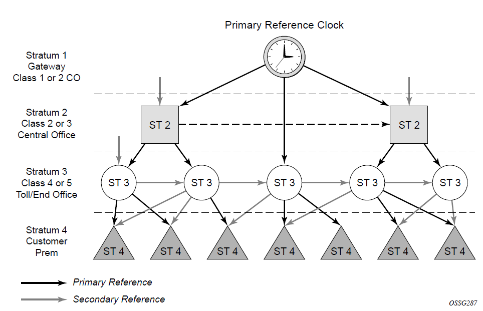
The architecture shown in the preceding figure provides the following benefits:
It limits the need for high quality clocks at each network element and only requires that they reliably replicate input to remain traceable to its reference.
It uses reliable physical media to provide transport of the timing signal. It does not consume any bandwidth and requires limited additional processing.
The synchronization network is designed so a clock always receives timing from a clock of equal or higher stratum or quality level. This ensures that if an upstream clock has a fault condition (for example, loses its reference and enters a holdover or free-run state) and begins to drift in frequency, the downstream clock will be able to follow it. For greater reliability and robustness, most offices and nodes have at least two synchronization references that can be selected in priority order (such as primary and secondary).
Further levels of resiliency can be provided by designing a capability in the node clock that will operate within prescribed network performance specifications without any reference for a specified timeframe. A clock operating in this mode is said to hold the last known state over (or holdover) until the reference lock is once again achieved. Each level in the timing hierarchy is associated with minimum levels of network performance.
Each synchronization capable port can be independently configured to transmit data using the node reference timing. In addition, some TDM channels can use adaptive timing or loop timing.
Transmission of a reference clock through a chain of Ethernet equipment requires that all equipment supports Synchronous Ethernet. A single piece of equipment that is not capable of performing Synchronous Ethernet breaks the chain. Ethernet frames will still get through but downstream devices should not use the recovered line timing because it will not be traceable to an acceptable stratum source.
Central synchronization subsystem
The timing subsystem has a central clock located on the CPM. The timing subsystem performs several functions of the network element clock as defined by Telcordia (GR-1244-CORE) and ITU-T G.781 standards.
The central clock uses the available timing inputs to train its local oscillator. The number of timing inputs available to train the local oscillator varies per platform. The priority order of these references must be specified. This is a simple ordered list of inputs: (ref1, ref2, BITS (if available)).
The CPM clock output can drive the clocking for all line cards in the system. The routers support selection of the node reference using Quality Level (QL) indications. The recovered clock can derive its timing from one of the references available on that platform.
The recovered clock can derive the timing from any of the following references (also shown in Logical model of synchronization reference selection on 7210 SAS):
synchronous Ethernet ports
On the 7210 SAS-T (includes all variants), 7210 SAS-R6, 7210 SAS-R12, 7210 SAS-Sx 1/10GE (all variants), 7210 SAS-S 1/10GE (all variants), and 7210 SAS-Sx 10/100GE
1588v2/PTP timeReceiver port
On the 7210 SAS-T (includes all variants), 7210 SAS-R6, 7210 SAS-R12, 7210 SAS-Sx 1/10GE (all variants)
Logical model of synchronization reference selection on 7210 SAS shows a logical model of synchronization reference selection for the platforms, and Synchronization options for 7210 SAS platforms provides a list of supported interfaces for each platform.
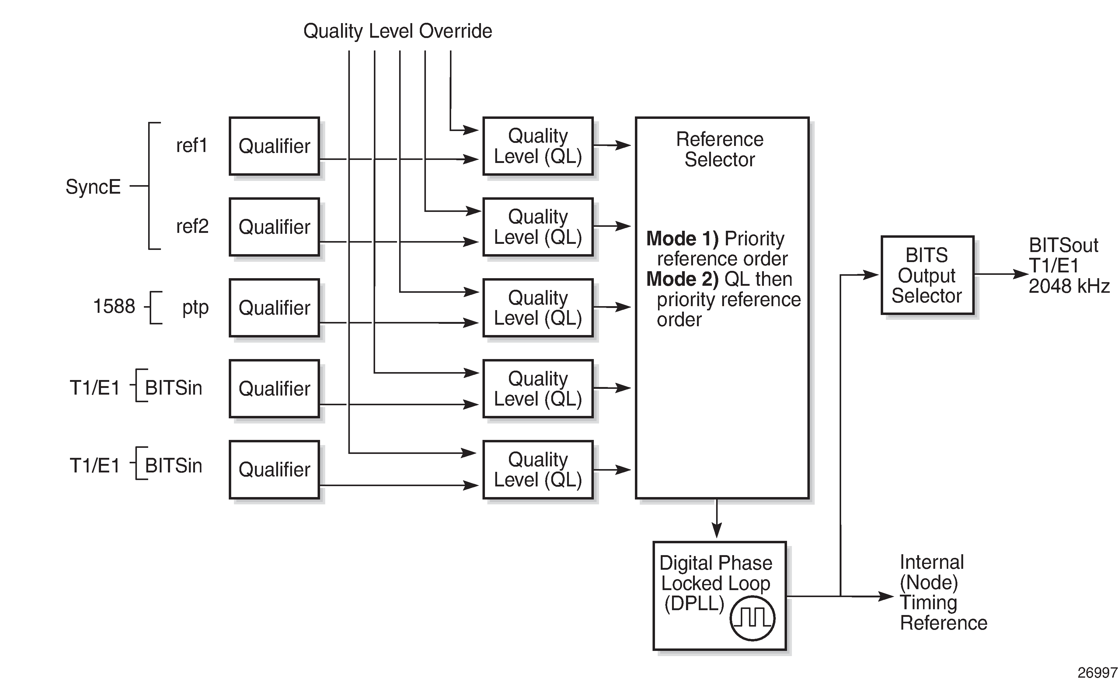
On the 7210 SAS-Mxp, 7210 SAS-R6, 7210 SAS-R12, and 7210 SAS-T, in addition to PTP and SyncE references, the recovered clock can be configured to derive the timing (frequency reference) from the BITS interface.
When quality Level (QL) selection mode is disabled, the reversion setting controls when the central clock can reselect a previously failed reference.
The following table lists the selection followed for two references in both revertive and non-revertive modes.
Status of reference A |
Status of reference B |
Active reference non-revertive case |
Active reference revertive case |
|---|---|---|---|
OK |
OK |
A |
A |
Failed |
OK |
B |
B |
OK |
OK |
B |
A |
OK |
Failed |
A |
A |
OK |
OK |
A |
A |
Failed |
Failed |
holdover |
holdover |
OK |
Failed |
A |
A |
Failed |
Failed |
holdover |
holdover |
Failed |
OK |
B |
B |
Failed |
Failed |
holdover |
holdover |
OK |
OK |
A or B |
A |
Synchronization options available on 7210 SAS platforms
The following table lists the synchronization options supported on 7210 SAS platforms. The 7210 SAS-Mxp, 7210 SAS-Sx 1/10GE, and 7210 SAS-Sx 10/100GE support these synchronization options only when operating in the standalone mode.
| Synchronization options | 7210 SAS platforms | ||||||
|---|---|---|---|---|---|---|---|
| T | S 1/10GE | R6 | R12 | Mxp1 | Sx 1/10GE1 | Sx 10/100GE1 | |
|
SyncE with SSM (1GE and 10G/E fiber ports) |
✓ |
✓ |
✓ |
✓ |
✓ |
✓ |
✓ |
|
SyncE with fixed copper ports2 |
✓3 |
✓4 |
✓ |
✓ |
✓5 |
✓6 |
|
|
Adaptive Clock Recovery (ACR) |
|||||||
|
1588v2/PTP with port-based timestamps (both for frequency and time – also called PTP pure mode) |
✓ |
✓ |
✓ |
✓ |
✓ |
||
|
1588v2/PTP with port-based timestamps (time only with SyncE or BITS (if supported) used for frequency recovery – also called PTP hybrid mode) |
✓ |
✓ |
✓ |
✓ |
✓ |
✓ 7 |
|
|
PTP end-to-end (E2E) transparent clock |
✓ |
✓ |
|||||
|
BITS |
✓ 8 |
✓9 |
✓9 |
✓ |
|||
|
1pps and 10MHz interfaces |
✓10 |
✓10 |
✓10 |
✓10 |
|||
Synchronization Status Messages
Synchronization Status Messages (SSM) are supported on devices that support Synchronous Ethernet. SSM allows the synchronization distribution network to determine the quality level of the clock sourcing a specific synchronization trail and also allows a network element to select the best of multiple input synchronization trails. SSMs are defined for various transport protocols (including SONET/SDH, T1/E1, and Synchronous Ethernet), for interaction with office clocks (such as BITS or SSUs) and embedded network element clocks.
SSM allows equipment to autonomously provision and reconfigure (by reference switching) their synchronization references, while helping to avoid the creation of timing loops. These messages are particularly useful for synchronization re-configurations when timing is distributed in both directions around a ring.
DS1 signals
DS1 signals can carry the quality level value of the timing source information using the SSM that is transported within the 1544 kb/s signal Extended Super Frame (ESF) Data Link (DL), as described in ITU-T Recommendation G.704. No such provision is extended to SF formatted DS1 signals.
The format of the ESF DL messages is 0xxx xxx0 1111 1111, with the rightmost bit transmitted first. The 6 bits denoted by xxx xxx contain the message; some of these messages are reserved for synchronization messaging. It takes 32 frames (4 ms) to transmit all 16 bits of a complete DL.
E1 signals
E1 signals can carry the quality level value of the timing source information using the SSM, as described in ITU-T Recommendation G.704.
One of the Sa4 to Sa8 bits is allocated for SSMs; choosing the Sa bit that carries the SSM is user-configurable. To prevent ambiguities in pattern recognition, it is necessary to align the first bit (San1) with frame 1 of a G.704 E1 multiframe.
The San bits are numbered (n = 4, 5, 6, 7, 8). A San bit is organized as a 4-bit nibble San1 to San4. San1 is the most significant bit, and San4 is the least significant bit.
The message set in San1 to San4 is a copy of the set defined in SDH bits 5 to 8 of byte S1.
Synchronous Ethernet
Traditionally, Ethernet-based networks employ a physical layer transmitter clock derived from an inexpensive +/-100ppm crystal oscillator and the receiver locks onto it. Because data is packetized and can be buffered, there is no need for long-term frequency stability or for consistency between frequencies of different links.
Synchronous Ethernet is a variant of the line timing that derives the physical layer transmitter clock from a high-quality frequency reference, replacing the crystal oscillator with a frequency source traceable to a primary reference clock. This change is transparent to the other Ethernet layers and does not affect their operation. The receiver at the far end of the link is locked to the physical layer clock of the received signal, and ensures access to a highly accurate and stable frequency reference. In a manner analogous to conventional hierarchical network synchronization, this receiver can lock the transmission clock of other ports to this frequency reference, and establish a fully time-synchronous network.
Unlike methods that rely on sending timing information in packets over an unclocked physical layer, Synchronous Ethernet is not affected by impairments introduced by higher levels of networking technology (packet loss, packet delay variation). The frequency accuracy and stability in Synchronous Ethernet typically exceeds networks with unsynchronized physical layers.
Synchronous Ethernet allows operators to gracefully integrate existing systems and future deployments into a conventional industry-standard synchronization hierarchy. The concept is analogous to SONET/SDH system timing capabilities. The operator can select any (optical) Ethernet port as a candidate timing reference. The recovered timing from this port is used to time the system (for example, the CPM will lock to this provisioned reference selection). The operator then can ensure that all system output is locked to a stable traceable frequency source.
The use of Synchronous Ethernet as a candidate reference and for distribution of recovered reference is supported on all 7210 SAS platforms as described in this document, except those operating in standalone-VC mode.
Synchronous Ethernet using fiber Ethernet ports, including 10G and 100G (if available), is supported on all 7210 SAS platforms as described in this document, except those operating in standalone-VC mode.
Please ensure that the SFP or XFP or SFP+ parts used with the SFP, XFP, and SFP+ ports support Synchronous Ethernet.
Synchronous Ethernet is not supported on virtual chassis (VCs).
Synchronous Ethernet using fixed copper ports is supported only on the 7210 SAS-T, 7210 SAS-R6, 7210 SAS-R12, 7210 SAS-Sx 1/10GE, 7210 SAS-S 1/10GE and 7210 SAS-Mxp. The fixed copper ports can be used as a candidate reference or for distribution of recovered reference . If the port is a fixed copper Ethernet port and in 1000 BASE-T mode of operation, there is a dependency on the 802.3 link timing for the Synchronous Ethernet functionality (see ITU-T G.8262). The 802.3 standard link timing states must align with the desired direction of Synchronous Ethernet timing flow. When a fixed copper Ethernet port is specified as an input reference for the node or when it is removed as an input reference for the node, an 802.3 link auto-negotiation is triggered to ensure the link timing aligns properly.
The SSM of Synchronous Ethernet uses an Ethernet OAM PDU that uses the slow protocol subtype. For a complete description of the format and processing, see ITU-T G.8264.
Clock source quality level definitions
This section describes the clock source quality levels identified for tracking network timing flow in accordance with the network deployment options defined in Recommendation G.803 and G.781. The Option I network is developed on the original European SDH model; Option II network is a network developed on the North American SONET model.
In addition to the QL values received over SSM of an interface, the standards define the following additional codes for internal use:
QL INVx is generated internally by the system if and when an unallocated SSM value is received, where x represents the binary value of this SSM. Within the SR OS, these independent values are assigned as the single value QL-INVALID.
QL FAILED is generated internally by the system if and when the terminated network synchronization distribution trail is in the signal fail state.
The internal quality level of QL-UNKNOWN is used to differentiate from a received QL-STU code, but is equivalent for the purposes of QL selection.
The following table lists the synchronization message coding and source priorities for SSM values received on port.
SSM value received on port |
||||
|---|---|---|---|---|
SDH interface SyncE interface in SDH mode |
SONET interface SyncE interface in SONET mode |
E1 interface |
T1 interface (ESF) |
Internal relative quality level |
0010 (prc) |
0001 (prs) |
0010 (prc) |
00000100 11111111 (prs) |
1. Best quality |
0000 (stu) |
00001000 11111111 (stu) |
2. |
||
0111 (st2) |
00001100 11111111 (ST2) |
3. |
||
0100 (ssua) |
0100 (tnc) |
0100 (ssua) |
01111000 11111111 (TNC) |
4. |
1101 (st3e) |
01111100 11111111 (ST3E) |
5. |
||
1000 (ssub) |
1000 (ssub) |
6. |
||
1010 (st3/eec2) |
00010000 11111111 (ST3) |
7. |
||
1011 (sec/eec1) |
1011 (sec) |
8. Lowest quality qualified in QL-enabled mode |
||
1100 (smc) |
00100010 11111111 (smc) |
9. |
||
00101000 11111111 (st4) |
10. |
|||
1110 (pno) |
01000000 11111111 (pno) |
11. |
||
1111 (dnu) |
1111 (dus) |
1111 (dnu) |
00110000 11111111 (dus) |
12. |
Any other |
Any other |
Any other |
N/A |
13. QL_INVALID |
14. QL_FAILED |
||||
15. QL_UNC |
||||
The following table lists the synchronization message coding and source priorities for SSM values transmitted by interface type.
SSM values to be transmitted by interface of type |
||||
|---|---|---|---|---|
Internal relative quality level |
SDH interface SyncE interface in SDH mode |
SONET interface SyncE interface in SONET mode |
E1 interface |
T1 interface (ESF) |
1. Best quality |
0010 (prc) |
0001 (PRS) |
0010 (prc) |
00000100 11111111 (PRS) |
2. |
0100 (ssua) |
0000 (stu) |
0100 (ssua) |
00001000 11111111 (stu) |
3. |
0100 (ssua) |
0111 (st2) |
0100 (ssua) |
00001100 11111111 (st2) |
4. |
0100 (ssua) |
0100 (tnc) |
0100 (ssua) |
01111000 11111111 (tnc) |
5. |
1000 (ssub) |
1101 (st3e) |
1000 (ssub) |
01111100 11111111 (st3e) |
6. |
1000 (ssub) |
1010 (st3/eec2) |
1000 (ssub) |
00010000 11111111 (st3) |
7. |
1011 (sec/eec1) |
1010 (st3/eec2) |
1011 (sec) |
00010000 11111111 (st3) |
8. Lowest quality qualified in QL-enabled mode |
1011 (sec/ eec1) |
1100 (smc) |
1011 (sec) |
00100010 11111111 (smc) |
9. |
1111 (dnu) |
1100 (smc) |
1111 (dnu) |
00100010 11111111 (smc) |
10. |
1111 (dnu) |
1111 (dus) |
1111 dnu |
00101000 11111111 (st4) |
11. |
1111 (dnu) |
1110 (pno) |
1111 (dnu) |
01000000 11111111 (pno) |
12. |
1111 (dnu) |
1111 (dus) |
1111 (dnu) |
00110000 11111111 (dus) |
13. |
1111 (dnu) |
1111 (dus) |
1111 (dnu) |
00110000 11111111 (dus) |
14. |
1111 (dnu) |
1111 (dus) |
1111 (dnu) |
00110000 11111111 (dus) |
15. |
1011 (sec/eec1) |
1010 (st3/eec2) |
1011 (sec) |
00010000 11111111 (st3) |
IEEE 1588v2 PTP
The Precision Time Protocol (PTP) is a timing-over-packet protocol defined in the IEEE 1588v2 standard 1588 PTP 2008.
PTP may be deployed as an alternative timing-over-packet option to ACR. PTP provides the capability to synchronize network elements to a Stratum-1 clock or primary reference clock (PRC) traceable source over a network that may or may not be PTP-aware. PTP has several advantages over ACR. It is a standards-based protocol, has lower bandwidth requirements, can transport both frequency and time, and can potentially provide better performance.
The basic types of PTP devices are the following:
ordinary clock
boundary clock
end-to-end transparent clock
peer-to-peer transparent clock
Synchronization options for 7210 SAS platforms lists the 7210 SAS platform support for the different types of PTP devices.
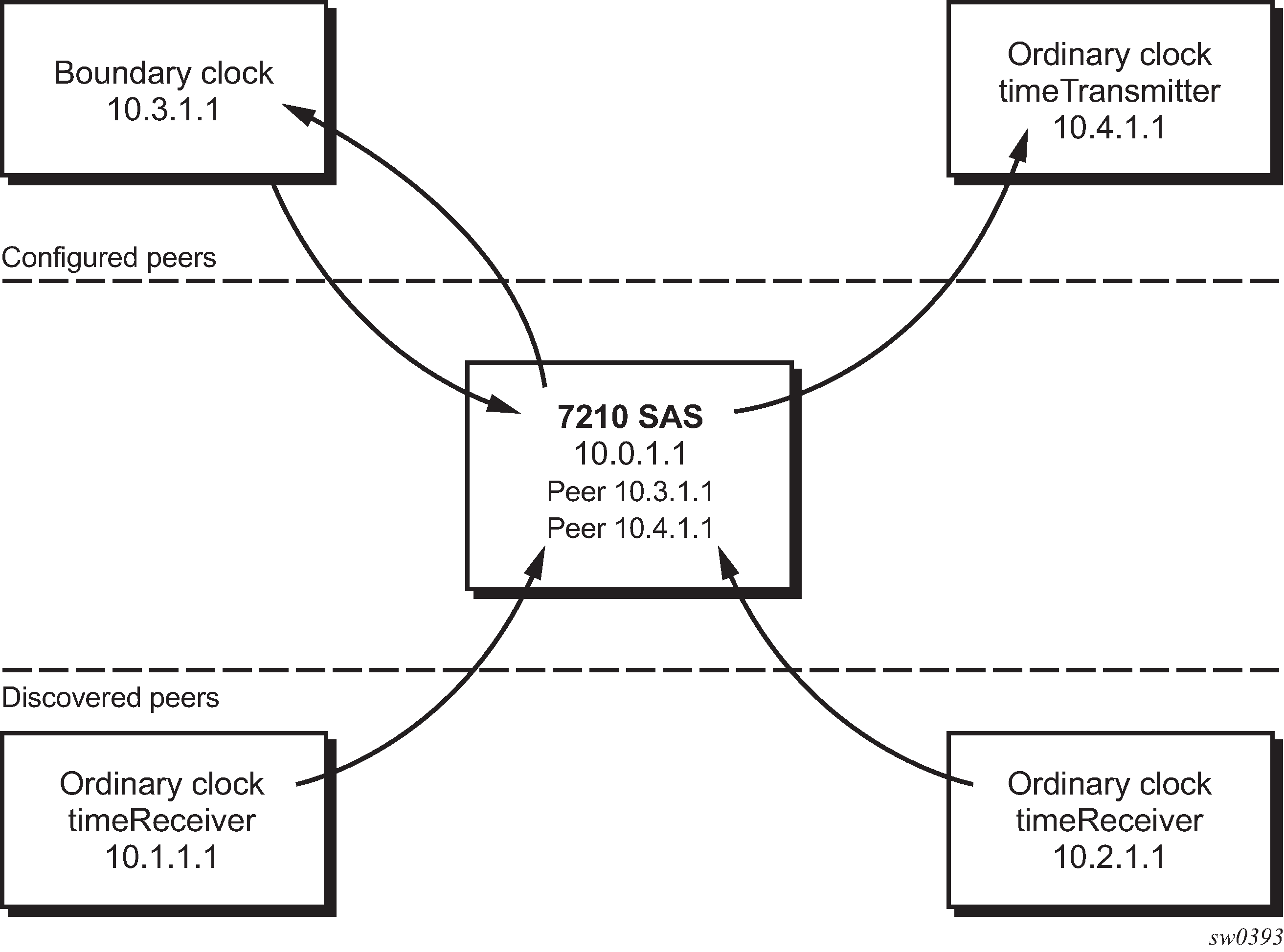
The 7210 SAS communicates with peer 1588v2 clocks, as shown in the following figure. These peers can be ordinary clock timeReceivers or boundary clocks. The communication can be based on either unicast IPv4 sessions transported through IP interfaces or Ethernet multicast PTP packets transported through an Ethernet port.
IP/UDP unicast and Ethernet multicast support for the 7210 SAS platforms is listed in the following table.
PTP is supported on all 7210 SAS platforms as described in this document, except the 7210 SAS-Sx 10/100GE and 7210 SAS-Sx/S 1/10GE operating in standalone-VC mode. See Configuration guidelines and restrictions for PTP for a list of PTP profiles, and the configuration guidelines and restrictions.
Platform |
IP/UDP Unicast |
Ethernet Multicast |
|---|---|---|
7210 SAS-T |
Yes |
Yes |
7210 SAS-Mxp |
Yes |
Yes |
7210 SAS-Sx 1/10GE |
Yes |
Yes11 |
7210 SAS-S 1/10GE |
No |
No |
7210 SAS-Sx 10/100GE12 |
No |
Yes11 |
7210 SAS-R6 |
Yes |
Yes13 |
7210 SAS-R12 |
Yes |
Yes13 |
Unicast IP sessions support two types of peers: configured and discovered. The 7210 SAS operating as an ordinary clock timeReceiver or as a boundary clock must have configured peers for each PTP neighbor clock from which it might accept synchronization information. The 7210 SAS initiates unicast sessions with all configured peers. A 7210 SAS operating as a boundary clock accepts unicast session requests from external peers. If the peer is not configured, it is considered a discovered peer. The 7210 SAS can deliver synchronization information toward discovered peers (that is, timeReceivers).
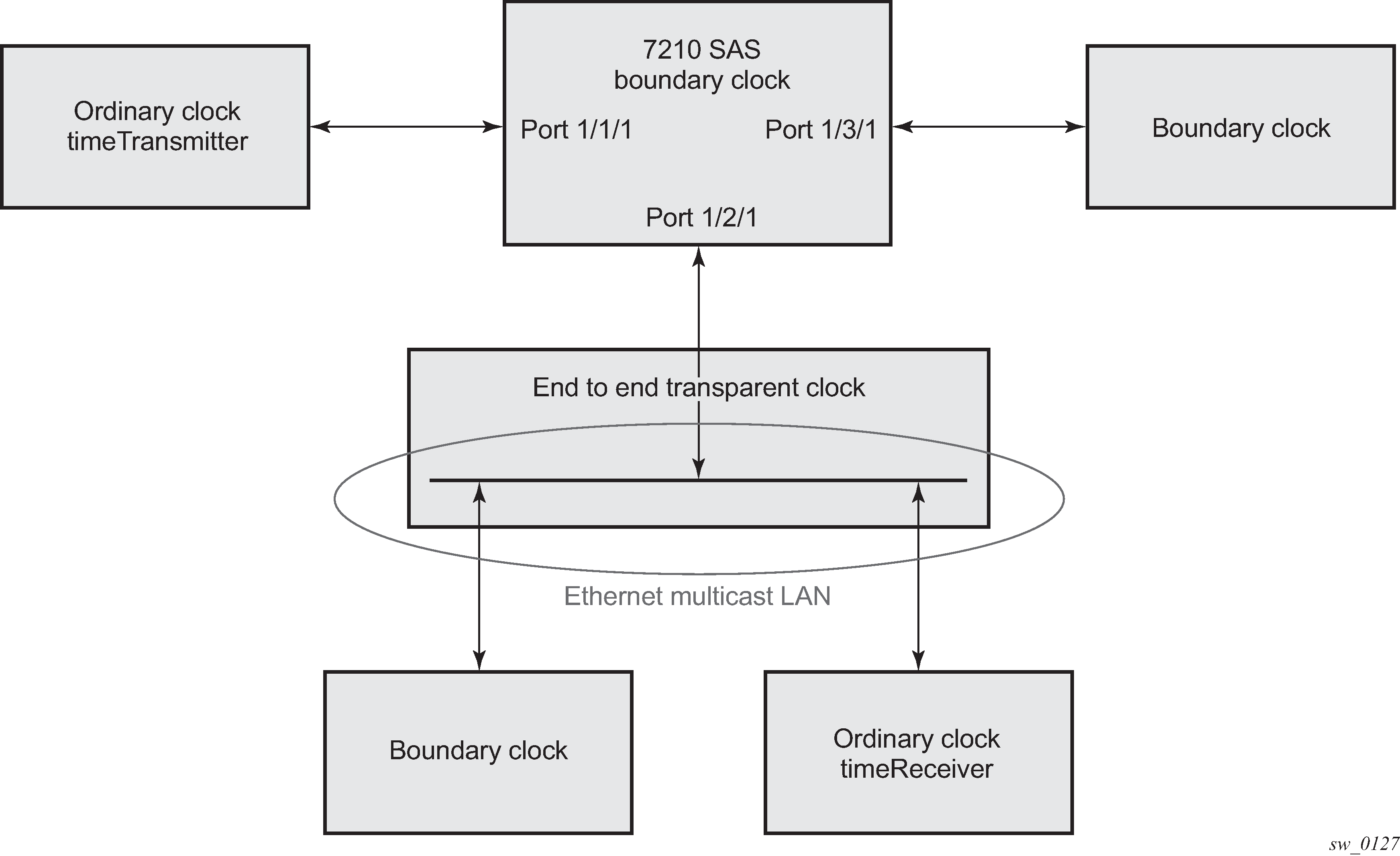
For Ethernet multicast operation, the node listens for and transmits PTP messages using the configured multicast MAC address. Neighbor clocks are discovered via messages received through an enabled Ethernet port. The 7210 SAS supports only one neighbor PTP clock connecting into a single port (see Ethernet multicast ports); multiple PTP clocks connecting through a single port are not supported. This might be encountered with the deployment of an Ethernet multicast LAN segment between the 7210 SAS and the neighbor PTP ports using an end-to-end transparent clock or an Ethernet switch. The use of an Ethernet switch is not recommended because of PDV and potential performance degradation, but it can be used if appropriate for the application.
The 7210 SAS does not allow simultaneous PTP operations using both unicast IPv4 and Ethernet multicast. A change of profile to G.8275.1 or from G.8275.1 to another profile requires a reboot of the node.
The following figure shows one neighbor PTP clock connecting into a single port.
7210 SAS platforms do not support ordinary clock timeTransmitter configuration.
The IEEE 1588v2 standard includes the concept of PTP profiles. These profiles are defined by industry groups or standards bodies that define the use of IEEE 1588v2 for specific applications.
The following profiles are supported for 7210 SAS platforms (as described in IP/UDP unicast and Ethernet multicast support):
IEEE 1588v2 (default profile)
ITU-T Telecom profile (G.8265.1)
ITU-T Telecom profile for time with full timing support (G.8275.1)
The following caveats apply to G.8275.1 support. See sectionConfiguration guidelines and restrictions for PTP for configuration guidelines and restrictions.
PTP with Ethernet encapsulation is only supported with G.8275.1 profiles.
PTP over IP encapsulation is only with the IEEE 1588v2 and G.8265.1 profiles; it is not supported for G.8275.1 profiles.
When a 7210 SAS receives Announce messages from one or more configured peers or multicast neighbors, it executes a Best timeTransmitter Clock Algorithm (BTCA) to determine the state of communication between itself and the peers. The system uses the BTCA to create a hierarchical topology, allowing the flow of synchronization information from the best source (the grandmaster clock) out through the network to all boundary and timeReceiver clocks. Each profile has a dedicated BTCA.
If the profile setting for the clock is "ieee1588-2008", the precedence order for the BTCA is as follows:
priority1
clock class
clock accuracy
PTP variance (offsetScaledLogVariance)
priority2
clock identity
steps removed from the grandmaster
The 7210 SAS sets its local parameters as described in the following table.
Parameter |
Value |
|---|---|
clockClass |
248 – the 7210 SAS is configured as a boundary clock 255 – the 7210 SAS is configured as an ordinary clock timeReceiver |
clockAccuracy |
FE - unknown |
offsetScaledLogVariance |
FFFF – not computed |
clockIdentity |
Chassis MAC address following the guidelines of section 7.5.2.2.2 of IEEE 1588-2008 |
If the profile setting for the clock is "itu-telecom-freq" (ITU G.8265.1 profile), the precedence order for the best timeTransmitter selection algorithm is:
clock class
PTSF (Packet Timing Signal Fail) - Announce Loss (miss 3 Announce messages or do not get an Announce message for 6 seconds)
priority
The 7210 SAS sets its local parameters as described in the following table.
Parameter |
Value |
|---|---|
clockClass |
80-110 – value corresponding to the QL out of the central clock of the 7210 SAS as per Table 1/G.8265.1 255 – the 7210 SAS is configured as an ordinary clock timeReceiver |
The ITU-T profile is for use in environments with only ordinary clock timeTransmitters and timeReceivers for frequency distribution.
If the profile setting for the clock is "g8275dot1-2014", the precedence order for the best timeTransmitter selection algorithm is very similar to that used with the default profile. It ignores the priority1 parameter, includes a localPriority parameter, and includes the ability to force a port to never enter the timeReceiver state (master-only). The precedence is as follows:
clock class
clock accuracy
PTP variance (offsetScaledLogVariance)
priority2
localPriority
clock identity
steps removed from the grandmaster
The 7210 SAS sets its local parameters as described in the following table.
Parameter |
Value |
|---|---|
clockClass |
165 – the 7210 SAS is configured as a boundary clock and the boundary clock was previously locked to a grandmaster with clock class of 6 248 – the 7210 SAS is configured as a boundary clock 255 – the 7210 SAS is configured as an ordinary clock timeReceiver |
clockAccuracy |
FE – unknown |
offsetScaledLogVariance |
FFFF – not computed |
clockIdentity |
Chassis MAC address following the guidelines of section 7.5.2.2.2 of IEEE 1588-2008 |
The 7210 SAS supports a limited number of configured (possible timeTransmitter or neighbor boundary clocks) and a discovered peers (timeReceivers).These peers use the unicast negotiation procedures to request service from the 7210 SAS clock. A neighbor boundary clock counts as two peers (both a configured and a discovered peer) toward the maximum limit.
The number of configured Ethernet ports is not restricted.
On the 7210 SAS-Mxp, 7210 SAS-R6, 7210 SAS-R12, 7210 SAS-Sx 1/10GE, 7210 SAS-Sx 10/100GE 64SFP+ 4QSFP28, and 7210 SAS-T, there are limits on the number of timeReceivers enforced in the implementation for unicast and multicast timeReceivers.
Contact a Nokia technical support representative for scaling information about specific unicast message limits related to PTP.
The following figure shows the unicast negotiation procedure performed between a timeReceiver and a timeTransmitter clock that is selected to be the timeReceiver clock. The timeReceiver clock requests Announce messages from all peer clocks, but only requests Sync and Delay_Resp messages from the clock selected to be the timeTransmitter clock.
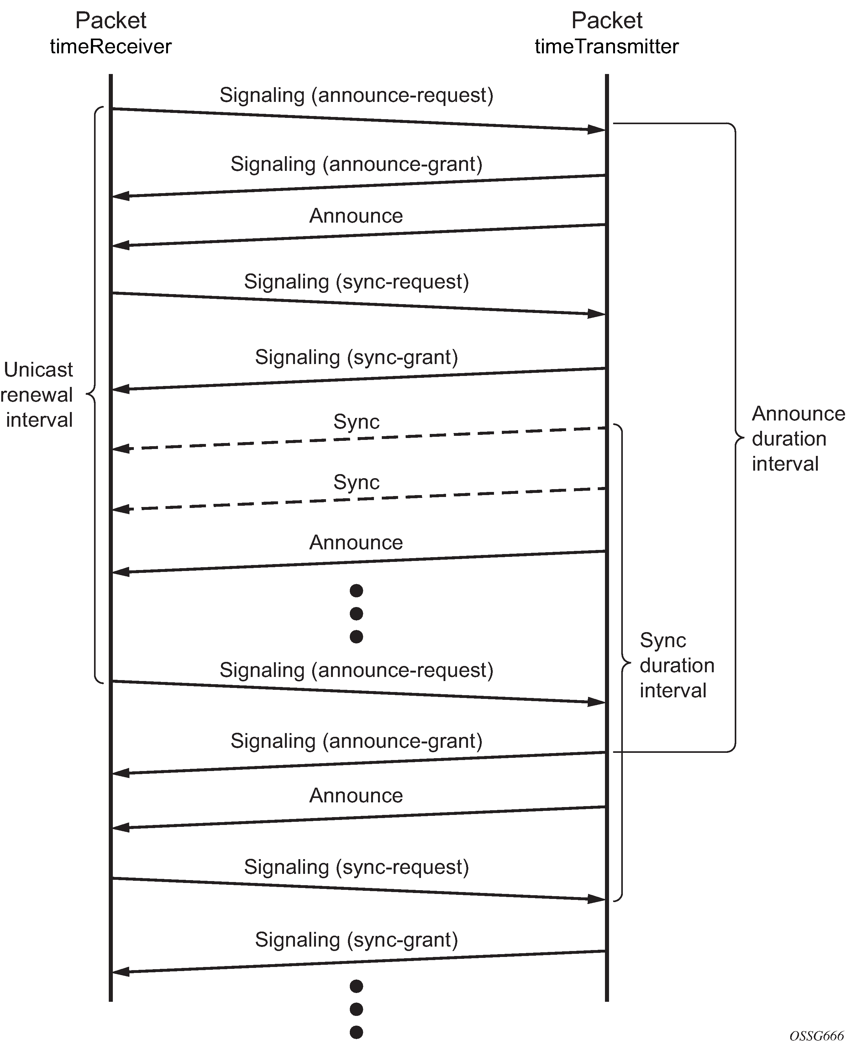
PTP clock synchronization
The IEEE 1588v2 standard synchronizes the frequency and time from a timeTransmitter clock to one or more timeReceiver clocks over a packet stream. This packet-based synchronization can be over IP/UDP unicast or Ethernet multicast.
As part of the basic synchronization timing computation, event messages are defined for synchronization messaging between the PTP timeReceiver clock and PTP timeTransmitter clock. A one-step or two-step synchronization operation can be used; the two-step operation requires a follow-up message after each synchronization message.
The 7210 SAS-Mxp, 7210 SAS-R6, 7210 SAS-R12, 7210 SAS-Sx 1/10GE, 7210 SAS-Sx 10/100GE 64SFP+ 4QSFP28, and 7210 SAS-T support only one-step timeTransmitter port operation.
All platforms can operate timeReceiver ports that receive PTP messages from a one-step or two-step timeTransmitter port.
During startup, the PTP timeReceiver clock receives synchronization messages from the PTP timeTransmitter clock before a network delay calculation is made. Before any delay calculation, the delay is assumed to be zero. A drift compensation is activated after a number of synchronization message intervals occur. The expected interval between the reception of synchronization messages is user-configurable.
The following figure shows the basic synchronization timing computation between the PTP timeReceiver clock and PTP best timeTransmitter; the offset of the timeReceiver clock is shown referenced to the best timeTransmitter signal during startup.

When the IEEE 1588v2 standard is used for distribution of a frequency reference, the timeReceiver calculates a message delay from the timeTransmitter to the timeReceiver based on the timestamps exchanged. A sequence of these calculated delays contains information about the relative frequencies of the timeTransmitter clock and timeReceiver clock, but also includes a noise component related to the PDV experienced across the network. The timeReceiver must filter the PDV effects to extract the relative frequency data and then adjust the timeReceiver frequency to align with the timeTransmitter frequency.
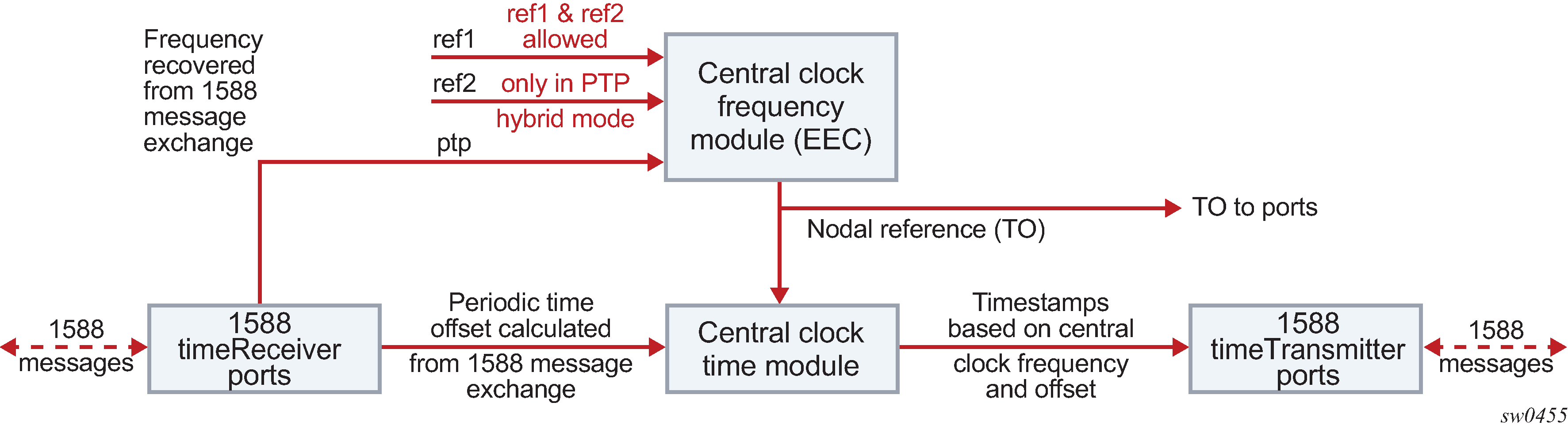
When the IEEE 1588v2 standard is used for distribution of time, the 7210 SAS calculates the offset between the 7210 SAS time base and the external timeTransmitter clock time base based on the four timestamps exchanged. The 7210 SAS determines the offset adjustment, and between these adjustments, it maintains the progression of time using the frequency from the central clock of the node. This allows time to be maintained using a Synchronous Ethernet input source even if the IEEE 1588v2 communications fail. When using IEEE 1588v2 for time distribution, the central clock should, at a minimum, have the PTP input reference enabled.
The following figure shows the logical model for using PTP/1588 for network synchronization.
Performance considerations
Although IEEE 1588v2 can be used on a network that is not PTP-aware, the use of PTP-aware network elements (boundary clocks) within the packet switched network improves synchronization performance by reducing the impact of PDV between the grandmaster clock and the timeReceiver clock. In particular, when IEEE 1588v2 is used to distribute high-accuracy time, such as for mobile base station phase requirements, the network architecture requires the deployment of PTP awareness in every device between the grandmaster and the mobile base station timeReceiver.
In addition, performance is also improved by the removal of any PDV caused by internal queuing within the boundary clock or timeReceiver clock. This is accomplished with hardware that is capable of port-based timestamping, which detects and timestamps the IEEE 1588v2 packets at the Ethernet interface.
PTP end-to-end Transparent Clock
This feature is supported only on the 7210 SAS-Sx 1/10GE and 7210 SAS-Sx 10/100GE.
The 7210 SAS devices support PTP end-to-end (E2E) Transparent Clock (TC) functionality, which allows the node to update the PTP correction fields (CFs) for the residence time of the PTP message. See Synchronization options for 7210 SAS platforms for a list of platforms that support this functionality.
A CLI option is provided to enable the PTP port-based hardware timestamp on ports that receive and forward PTP messages. To enable the TC function, PTP must not be enabled on the node. When the timestamp option is enabled, the node identifies standards-based messages and updates the CF for PTP IP/UDP multicast and unicast messages, and for the PTP Ethernet multicast and unicast messages. The CF is updated for the residence time of the PTP message. Downstream PTP timeReceivers that receive the PTP message use the updated CF to measure the delay between the timeTransmitter and themselves.
You can enable the TC option by running the configure>port>ethernet>ptp-hw-timestamp command on ports (both ingress and egress) on which residence time in the PTP message must be updated when the message is in transit through the node. You can disable the residence time update by running the no form of the command on both ingress and egress ports, as required. No additional CLI commands are required to enable the PTP TC option.
Nokia recommends the following operational guidelines and examples for enabling and using the PTP TC feature:
Assume port 1/1/10 is connected to a PTP timeTransmitter clock (using a port, a SAP, or an IES IP interface) and 1/1/15 is connected to a PTP timeReceiver clock (using a port, a SAP, or an IES IP interface).
To enable PTP TC in this scenario, you must enable the ptp-hw-timestamp command on both ports. To disable PTP TC, run the no form of the command on both ports.
Assume port 1/1/10 is connected to a PTP timeTransmitter clock (using a port, a SAP, or an IES IP interface) and ports 1/1/15 and 1/1/16 have PTP timeReceivers (using a port, a SAP, or an IES IP interface), with a PTP session to the PTP timeTransmitter clock that is connected on port 1/1/10.
To enable PTP TC, the ptp-hw-timestamp command must be enabled on all three ports.
In this scenario, it is not possible to disable PTP TC only towards the timeReceiver connected on port 1/1/15. The functionality must be disabled on all three ports.
Additionally, note that the PTP messages coming in on port 1/1/10 are not forwarded out of any ports other than 1/1/15 and 1/1/16, when the ptp-hw-timestamp command is enabled on port 1/1/10. Nokia recommends that when a set of PTP ports are enabled for ptp-hw-timestamp, the operator must ensure that PTP messages are forwarded to only the specific set of ports where the TC option is enabled, and not to other ports. Forwarding PTP messages to other ports that do not belong to the specific set may result in incorrect updates.
You can enable PTP TC for a set of SAPs and also transparently forward PTP packets on other SAPs, while both SAPs share a common uplink to forward PTP messages. To implement this scenario, use MPLS tunnels with network ports as the uplinks. Nokia recommends the following configuration.
PTP hardware port-based timestamping must be disabled on the access ports where SAPs are configured. These access ports are typically used to connect to either PTP timeTransmitter or PTP timeReceivers that need to establish and exchange PTP messages transparently.
PTP hardware port-based timestamping must be enabled on the access ports where SAPs are configured and the TC function is required. These access ports are typically used to connect to either the PTP timeTransmitter or PTP timeReceivers.
PTP hardware port-based timestamping must be enabled on the network ports where the MPLS tunnels originate and terminate. In this case, the PTP TC function updates only the PTP messages that are not MPLS encapsulated.
See PTP message transparent forwarding for additional support information.
PTP message transparent forwarding
On bootup, port-based hardware timestamping is enabled by default on all ports on the 7210 SAS-Mxp, 7210 SAS-R6, 7210 SAS-R12, 7210 SAS-Sx 1/10GE, 7210 SAS-Sx 10/100GE 64SFP+ 4QSFP28, and 7210 SAS-T, and the node processes both transit packets and locally destined PTP packets. Use the ptp-hw-timestamp command to disable port-based hardware timestamping in the following cases:
to allow the node to transparently forward PTP packets when MPLS uplinks are used
when PTP is enabled and used to synchronize and time the node (that is, PTP messages are originated and terminated by the node acting as a PTP OC-timeReceiver or BC)
on ports that receive PTP packets that will be forwarded transparently
When PTP port-based hardware timestamp is disabled, the node does not update the correction field in PTP messages. See the 7210 SAS-Mxp, R6, R12, S, Sx, T Interface Configuration Guide for more information about the ptp-hw-timestamping command.
For example, to enable transparent forwarding of PTP packets over MPLS tunnels, when access ports with SAPs are used to connect the PTP timeTransmitter or PTP timeReceivers, the ptp-hw-timestamp command can be used to disable PTP port-based hardware timestamping on these access ports.
The ptp-hw-timestamp command is only supported on the 7210 SAS-Mxp, 7210 SAS-R6, 7210 SAS-R12, 7210 SAS-Sx 1/10GE, 7210 SAS-Sx 10/100GE 64SFP+ 4QSFP28, and 7210 SAS-T. Port-based hardware timestamping can be used for transparent PTP packet forwarding if PTP is enabled and used to time the node (that is, PTP messages are originated and terminated by the node acting as a PTP OC-timeReceiver or BC).
The following guidelines must be considered for transparent PTP packet forwarding:
By default, PTP port-based hardware timestamping is enabled on all ports at bootup. To allow transparent PTP packet forwarding, the feature must be disabled using the configure>port>no ptp-hw-timestamp command.
On 7210 SAS-Mxp, 7210 SAS-R6, 7210 SAS-R12, 7210 SAS-Sx 1/10GE, 7210 SAS-Sx 10/100GE 64SFP+ 4QSFP28, and 7210 SAS-T, if the ptp-hw-timestamp command is enabled by executing the command on a set of ports, the node processes PTP packets that transit those ports to update the correction field for the packet residence time in the node. This allows accurate computation by PTP time and frequency recovery algorithms on PTP timeReceiver clocks that are connected to those ports.
The command to enable PTP hardware timestamps for packets transiting the node should be configured on both the ingress and egress port where PTP packets are expected to be received and sent from (and where they need to be processed to update correction time). Configuring the PTP hardware timestamp command on only the ingress port or egress port is not recommended because this will result in incorrect updates to the correction field.
For 7210 SAS-R6 and 7210 SAS-R12 platforms with IMM-b (IMMv2) and IMM-c cards, and for the 7210 SAS-Mxp and 7210 SAS-Sx 1/10GE, to enable transparent forwarding of PTP packets over MPLS tunnels, PTP hardware port-based timestamping must be disabled on the access ports where SAPs are configured. These access ports are used to connect to either PTP timeTransmitter or PTP timeReceivers that need to establish and exchange PTP messages transparently. PTP hardware port-based timestamping does not need to be disabled on the network ports where the MPLS tunnels originate and terminate. This means that these network ports can be used for PTP packet exchange when the node is a PTP boundary clock or ordinary clock timeReceiver. If the requirement is to forward PTP packets transparently when MPLS uplinks are not used or when a hybrid port with a SAP is used, PTP hardware port-based timestamping must be disabled on the access port and hybrid port.
On the 7210 SAS-Mxp and 7210 SAS-Sx 1/10GE, PTP messages for the G.8265.1 and IEEE 1588v2 profiles are transparently forwarded only for a VPRN service on which hardware timestamping is enabled on the access port. This restriction only applies to PTP packets that are using IP/UDP unicast encapsulation.
To enable transparent forwarding of PTP packets over MPLS tunnels on the 7210 SAS-T, you must disable hardware timestamping on access ports where SAPs are configured, and on the MPLS tunnel originating and terminating network ports. Consequently, these network ports cannot be used for PTP packet exchange when the node is a PTP boundary clock or ordinary clock timeReceiver.
To use the node as a PTP boundary clock or ordinary clock timeReceiver, you must use separate ports. In other words, a different access port, network port, or hybrid port must be used for PTP message exchange when this node is configured to be a PTP boundary clock or ordinary clock timeReceiver, and it cannot be any of the ports (either ingress or egress ports) on which PTP packets are forwarded transparently.
PTP capabilities
PTP messages are supported through IPv4 unicast with a fixed IP header size. The following table describes the supported message rates for timeReceiver and timeTransmitter states. The ordinary clock can only be used in the timeReceiver state. The boundary clock can be in both of these states.
Support message |
timeReceiver clock |
timeTransmitter clock |
|
|---|---|---|---|
Request rate |
Grant rate |
||
Min |
Max |
||
Announce |
1 packet every 2 seconds |
1 packet every 2 seconds |
1 packet every 2 seconds |
Sync |
User-configurable with an option to configure 8/16/32/64 packets/second |
8 packets/second |
16 or 64 packets/second14 |
Delay_Resp |
User-configurable with an option to configure 8/16/32/64 packets/second |
8 packets/second |
16 or 64 packets/second14 |
Duration |
300 seconds |
1 second |
1000 seconds |
State and statistics data for each timeTransmitter clock are available to assist in the detection of failures or unusual situations.
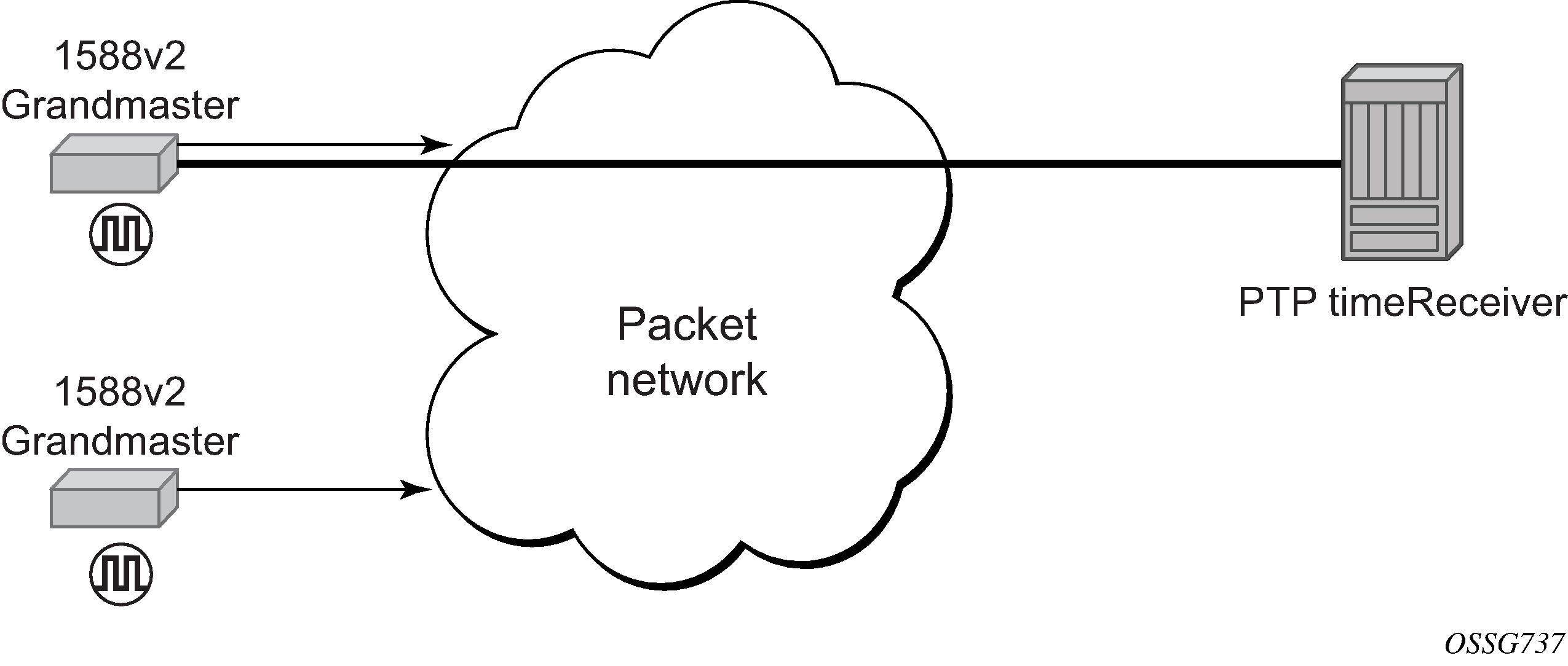
PTP ordinary timeReceiver clock for frequency
Traditionally, only clock frequency is required to ensure smooth transmission in a synchronous network. The PTP ordinary clock with timeReceiver capability on the 7210 SAS provides another option to reference a Stratum-1 traceable clock across a packet switched network. The recovered clock can be referenced by the internal SSU and distributed to all slots and ports.
The following figure shows a PTP ordinary timeReceiver clock network configuration.
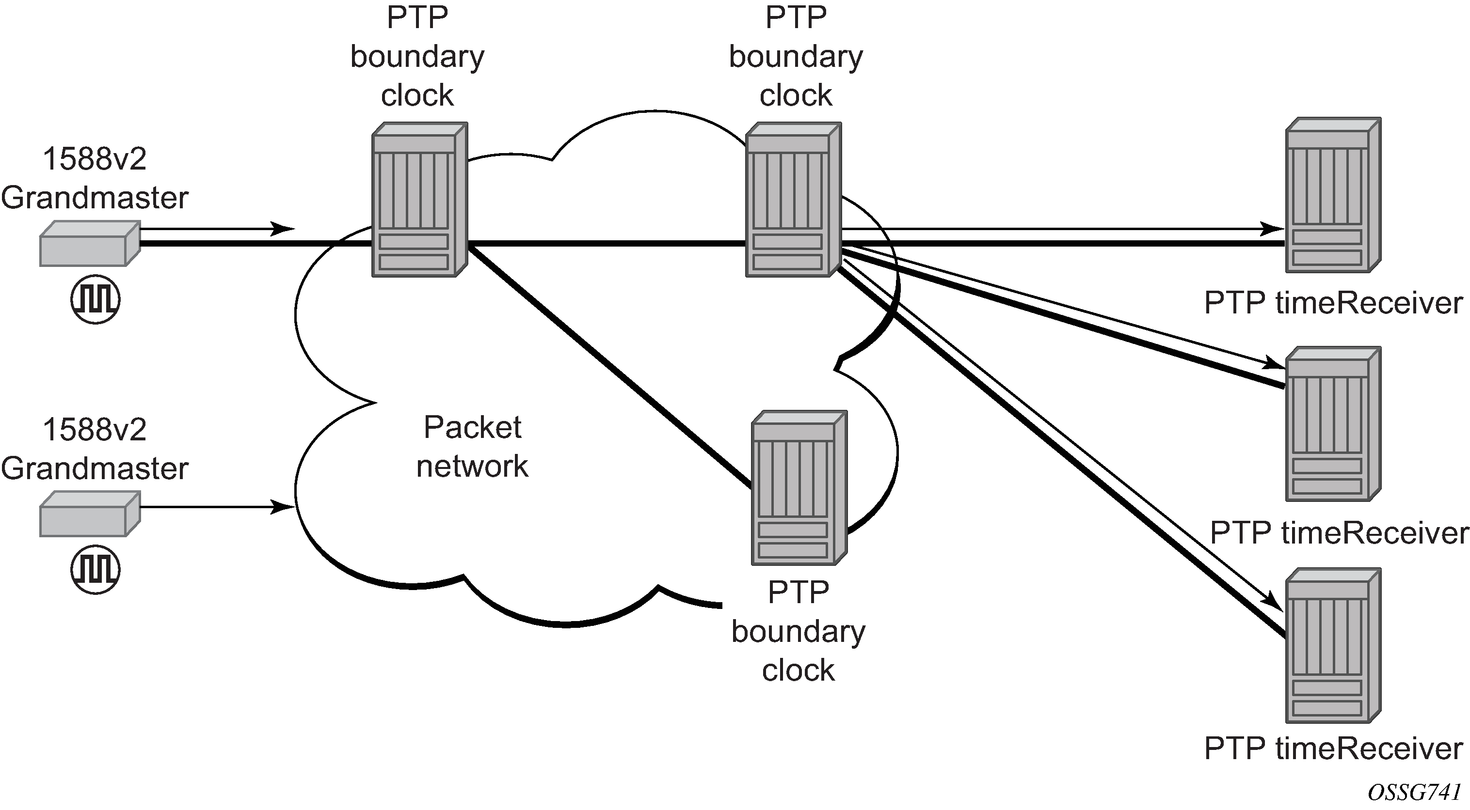
PTP boundary clock for frequency and time
Although IEEE 1588v2 can function across a packet network that is not PTP-aware, performance may be unsatisfactory and unpredictable. PDV across the packet network varies with the number of hops, link speeds, utilization rates, and the inherent behavior of routers. By using routers with boundary clock functionality in the path between the grandmaster clock and the timeReceiver clock, one long path over many hops is split into multiple shorter segments, allowing better PDV control and improved timeReceiver performance. This allows PTP to function as a valid timing option in more network deployments and allows for better scalability and increased robustness in certain topologies, such as rings.
Boundary clocks can simultaneously function as a PTP timeReceiver of an upstream grandmaster (ordinary clock) or boundary clock, and as a PTP timeTransmitter of downstream timeReceivers (ordinary clock) and boundary clocks. The time scale recovered in the timeReceiver side of the boundary clock is used by the timeTransmitter side of the boundary clock. This allows time distribution across the boundary clock.
The following figure shows routers with boundary clock functionality in the path between grandmaster clock and the timeReceiver clock.
1PPS and 10MHz output interface
The 7210 SAS-T, 7210 SAS-Mxp, 7210 SAS-R6, and 7210 SAS-R12 support 1PPS and 10 MHz output interfaces. These interfaces output the recovered signal from the system clock when PTP is enabled.
1pps and 10MHz signals are available only when PTP is enabled.
Configuration guidelines and restrictions for PTP
The following guidelines and restrictions apply for PTP configuration:
On 7210 SAS devices, only a single profile (IEEE 1588v2, G.8265.1, or G.8275.1) can be enabled for all PTP communications (both towards its timeTransmitter and timeReceiver connections) at any point in time.
The PTP G.8275.1 profile is supported only on the 7210 SAS-Mxp,7210 SAS-R6, 7210 SAS-R12, 7210 SAS-Sx 1/10GE, 7210 SAS-Sx 10/100GE 64SFP+ 4QSFP28, and 7210 SAS-T devices.
On the 7210 SAS-R12, the G.8275.1 profile is supported only for IMMv2 cards.
When using the G.8275.1 profile, the following restrictions apply:
The delay and sync requests are set to 16 pps by default and are not configurable.
The announce rate is set to 8 pps by default and is not configurable.
A change of profile to G.8275.1 or from G.8275.1 to another profile requires a reboot of the node.
Only a single multicast timeReceiver is supported per port.
PTP with Ethernet encapsulation is supported only with the G.8275.1 profile.
PTP over IP encapsulation is not supported with the G.8275.1 profile. It is supported only with the IEEE 1588v2 and G.8265.1 profiles.
PTP timeReceiver capability is available on all the ports on the 7210 SAS-Mxp, 7210 SAS-R6, 7210 SAS-R12, 7210 SAS-Sx 1/10GE, 7210 SAS-Sx 10/100GE 64SFP+ 4QSFP28, and 7210 SAS-T.
When changing the clock-type to or from a boundary clock on the 7210 SAS-Mxp, 7210 SAS-R6, 7210 SAS-R12, 7210 SAS-Sx 1/10GE, 7210 SAS-Sx 10/100GE 64SFP+ 4QSFP28, and 7210 SAS-T platforms, the node must be rebooted for the change to take effect. Nokia recommends taking appropriate measures to minimize service disruption during the reboot process.
The 7210 SAS-Mxp, 7210 SAS-R6, 7210 SAS-R12, 7210 SAS-Sx 1/10GE, and 7210 SAS-T support the use of PTP and SyncE as a reference simultaneously. That is, on these 7210 SAS platforms, the ref-order can be set to config>system>sync-if-timing>ref-order ref1 ref2 ptp.
The 7210 SAS-Mxp, 7210 SAS-R6, 7210 SAS-R12, 7210 SAS-Sx 1/10GE, 7210 SAS-Sx 10/100GE 64SFP+ 4QSFP28, and 7210 SAS-T support the PTP hybrid mode of operation. Frequency recovery is provided by the central clock through either SyncE or BITS, depending on which reference is configured. PTP is used for time recovery only. In this mode, the node can recover very stable frequency using a reduced PTP packet rate.
To enable PTP hybrid mode on the 7210 SAS-Mxp, 7210 SAS-R6, 7210 SAS-R12, 7210 SAS-Sx 1/10GE, and 7210 SAS-T, run the config>system>ptp>clock>freq-source ssu CLI command. To enable pure PTP mode, the user must run the command config>system>ptp>clock>freq-source ptp.
For a change of value from ssu to ptp (or vice-versa) to take effect, the operator must save the configuration changes and reboot the node.
On the 7210 SAS-R6 and 7210 SAS-R12, only the BITS1 port can be used to provide a reference to the system clock or to distribute the reference. The use of the BITS2 port is not supported.
On the 7210 SAS-T and 7210 SAS-Mxp, both the BITS1 and BITS2 ports can be used to provide a reference to the system clock or to distribute the reference.
On the 7210 SAS-Mxp, 7210 SAS-R6, 7210 SAS-R12, 7210 SAS-Sx 1/10GE, and 7210 SAS-T, an IP address must be configured under config>system>security>source-address>application ptp before PTP can be enabled for use. The use of the system IPv4 interface address or other loopback IPv4 interface address is recommended for PTP applications. The IPv4 address of an IPv4 interface over a port can also be used. The PTP software uses the configured IP address as the source IP address for both configured peers and discovered peers.
On the 7210 SAS-Mxp, 7210 SAS-R6, 7210 SAS-R12, and 7210 SAS-T, 1 pps and 10 MHz interface signals should only be used when PTP is enabled. Use these signals only after determining that the system is configured to use PTP as a reference and is locked to PTP.
The 7210 SAS-S 1/10GE does not support IEEE 1588v2 PTP.
On the 7210 SAS-Mxp, 7210 SAS-R6, 7210 SAS-R12, 7210 SAS-Sx 1/10GE, 7210 SAS-Sx 10/100GE 64SFP+ 4QSFP28, and 7210 SAS-T, PTP port-based timestamping is enabled by default on all ports for all PTP packets at system bootup:
When this feature is enabled, PTP packets are not forwarded transparently through the node, regardless of the service used and whether PTP is configured as a system clock reference. To enable transparent forwarding, see PTP message transparent forwarding.
Regardless of whether PTP is enabled (configure>sync-if-timing>ptp>no shutdown) or disabled (configure>sync-if-timing>ptp>shutdown), the timestamp value stored in the correction-field (CF) is updated for all PTP packets that are in transit through the node. This affects all PTP packets that are not originated or terminated on the node.
To prevent this occurrence, disable PTP port-based hardware timestamps on specific (all or select) ports by configuring the configure>port>no ptp-hw-timestamp CLI command on ports where PTP packets are in transit. When the feature is disabled, PTP packets in transit are transparently forwarded without changing the timestamp value.
Configuration example to use PTP and SyncE references
The 7210 SAS-Mxp, 7210 SAS-R6, 7210 SAS-R12, 7210 SAS-Sx 1/10GE, and 7210 SAS-T support the configuration of PTP and SyncE references at the same time. On these platforms, ref-order can be set to config>system>sync-if-timing>ref-order ref1 ref2 ptp.
The following configuration example shows the simultaneous use of PTP and SyncE references:
*A:SAS-T-B>config>system>sync-if-timing# info detail
----------------------------------------------
            ql-selection
            ref-order ptp ref1 ref2 --
> All three reference can be configured simultaneously
            ref1
                source-port 1/1/1
                no shutdown
                no ql-override
            exit
            ref2
                source-port 1/1/7
                no shutdown
                no ql-override
            exit
            ptp
                no ql-override
                no shutdown
            exit
            revert
----------------------------------------------
Management of 1830 VWM
This feature is only supported on the 7210 SAS-Mxp, 7210 SAS-R6, 7210 SAS-R12, and 7210 SAS-T.
The 7210 SAS supports the use and management of the 1830 VWM CWDM and 1830 VWM DWDM clip-on device. 1830 VWM is a family of cost-optimized managed WDM passive devices, which is add-on shelf/NE and provides CWDM/DWDM extension to devices that do not have in-built CWDM/DWDM capabilities. The 1830 VWM can act as a Fixed Channel Optical Add-Drop Multiplexer (FOADM) or multiplexer/demultiplexer unit. It allows operators to use the existing fiber (or use less fiber) and increase the bandwidth capacity available for carrying service traffic.
For more information about 1830 VWM, see 1830 VWM product user guides.
The 7210 SAS-Mxp, 7210 SAS-R6, 7210 SAS-R12, and 7210 SAS-T manage the 1830 VWM device using the Optical Management Console (OMC) port.
Introduction
The 1830 VWM device can be used in point-to-point or ring deployments to multiplex multiple CWDM/DWDM channels over a single fiber. Either the existing fiber is reused or a single fiber is used to meet the increasing demand for service bandwidth. Up to 8 fixed CWDM channels are multiplexed over a single fiber using this unit.
The following figure shows 5 CWDM channels that are multiplexed over a single fiber.
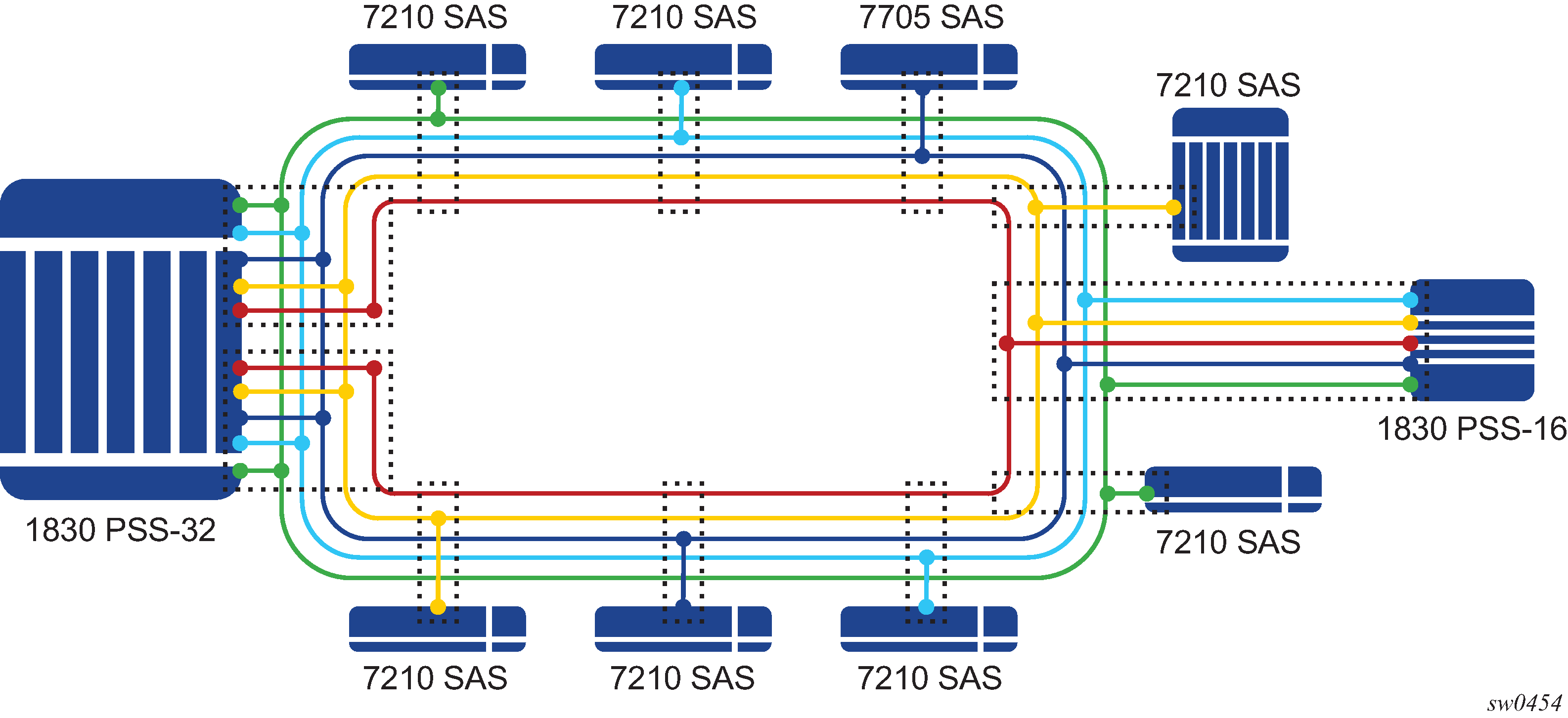
There are two types of ring locations. One is a channel termination location, with the 1830 PSS-32 that optically terminates all the channels using either the 4-channel or the 8-channel termination module. The second location is the intermediate OADM sites with the 7210 SAS. These sites use the CWDM passive units to add or drop a channel in both directions (east and west), for the node to process traffic. Additionally, these sites provide express lanes for all other channels (that is, those not processed locally by the node). The 1830 VWM provides an option to add or drop up to 1, 2, 4 channels of fixed wavelength for local processing by the node.
Feature description
The 1830 VWM clip-on device can be connected to the 7210 SAS node (the master shelf) using the USB interface or the OMC interface, depending on the interface supported by the 7210 SAS platform. Each of these clip-on devices is identified using the shelf ID, which is set on the rotary dial provided on the device.
To assist inventory management, the operator must use the configure>system>vwm-shelf vwm-shelf-id vwm-type vwm-type create CLI command to configure the vwm-shelf-id of the clip-on device attached to the 7210 SAS node. The vwm-shelf-id must match the shelf ID that is set on the rotary dial of the clip-on device. 7210 SAS devices use the configured vwm-shelf-id to communicate with the clip-on device. If the shelf IDs do not match, the 7210 SAS cannot communicate with the device and does not provide any information about the device. The 7210 SAS cannot detect a mismatch between the configured vwm-shelf-id and the shelf ID set on the rotary dial.
Depending on the type of supported interface, USB or OMC, the 7210 SAS node can manage only a fixed number of 1830 VWM devices. The software prevents attempts to configure more 1830 VWM devices than can be supported by the interface in use. Use the show command supported by the 7210 SAS devices to display the shelf inventory and alarm status information provided by the clip-on device.
In addition to inventory management, 7210 SAS supports provisioning of cards inserted into the slots available on the 1830 VWM devices. Before the card can be managed by the 7210 SAS, the user must provision the card and card type (also known as module type). The 7210 SAS detects and reports provisioning mismatches for the card. It also detects and reports insertion and removal of the card/module from the slot on the 1830 VWM device.
The 1830 DWDM supports active and passive units. The first 1830 DWDM device that is connected to a 7210 SAS node using the OMC port or the USB port must be equipped with active DWDM controllers; passive DWDM controllers can be used in the other chassis connected to the first device in a stacked configuration. In other words, the first 1830 DWDM device that is connected to the OMC port or the USB port of the 7210 SAS node must not be a passive 1830 DWDM device, but subsequent chassis in the stacked configuration can be equipped with passive DWDM controllers. See the 1830 VWM User Guide for information about making the decision to equip active or passive DWDM controllers on the other chassis in the stacked configuration.
The 7210 SAS also auto detects the device type when any supported device is connected to the USB interface. Only approved USB mass storage devices and optical clip-on devices plugged in to the USB port are recognized as valid devices. Use of unsupported devices results in the generation of an error log. A shelf created by the user will be operationally down when an unrecognized device is plugged into the USB port. The user can interchange the device connected to the USB port without requiring a reboot. For example, when the 7210 SAS is operating with a clip-on device you can pull out the clip-on device and plug-in a USB mass-storage device to copy image files or other files, and then plug back a clip-on device.
1830 CWDM shelf layout and description
The 1830 CWDM shelf shown in 1830 CWDM shelf layout is an example. For definitive information about the 1830 CWDM device and support, see the 1830 CWDM product manuals.
The following figure shows an example of the 1830 CWDM passive device.

In the preceding figure, Slot 1 is dedicated to the controller card. The controller card, which is named using the acronym EC-CW for the 1830 CWDM device, does not require explicit provisioning. The card type is automatically provisioned when the user configures the 1830 VWM shelf type.
If the controller card is not present in Slot 1 of the shelf, the 1830 CWDM device operates as a passive filter and is not managed by the 7210 SAS. The 7210 SAS provides inventory and equipment management capability only when the controller card is present in the shelf and connected to the 7210 SAS.
Slot 2 and Slot 3 shown in the preceding figure can be equipped with supported CWDM filter cards. The user must provision the cards that populate the slots. The 7210 SAS software checks to ensure a match between the equipped and provisioned card type; an event is logged if a mismatch is detected.
1830 DWDM shelf layout and description
The following figure shows the 1830 DWDM shelf and the entities that can be managed by 7210 SAS.

The following information applies to the management of the 1830 DWDM shown in the preceding figure:
Slot 1 and Slot 2 host the DWDM Power and Controller modules (either EC-DW or EC-DWA). These slots host the Equipment Controller; power is provided by the Service NE (using EC-DW unit) or the TRU (using EC-DWA unit) in accordance with the system configuration and the Equipment Controller used. A rotary switch located on the top side of the Equipment Controller is used to set the SHELF_ID. In a stacked configuration, each Shelf_ID must be uniquely set. The Shelf_ID must be identical for the active and standby controllers in a shelf.
Slot 1 and Slot 2 are not directly provisioned by the user in the 7210 SAS. The user must provision and configure the vwm-type managed by the 7210 SAS. The vwm-type can be provisioned as ec-cw, ec-dw, or ec-dwa, indicating that the shelf is a CWDM passive shelf or a DWDM passive shelf or a DWDM active shelf.
The first 1830 DWDM device that is connected to the OMC port or the USB port of the 7210 SAS node must be equipped with the active DWDM controllers; it must not be a passive 1830 DWDM device. However, subsequent chassis connected to the first 1830 DWDM device in a stacked configuration can be equipped with passive DWDM controllers.
Slot 3 and Slot 4 are capable of hosting DWDM filters (MUX/Demux), optical amplifiers, and Bulk Power Management (BPM) module. These slots must be explicitly provisioned on the 7210 SAS to allow management by the 7210 SAS. The 7210 SAS can manage the following cards:
all DWDM filter (remote and manual filter and all of 2-channel, 4-channel and 8-channel)
fan module
BPM module (which allows for the aggregation of 44 DWDM channels using SFD44 unit) is not supported
The 7210 SAS host tracks the following events related to the modules in Slot 3 and Slot 4:
line card/module removal and insertion
provisioning mismatch, if the provisioned line card does not match the equipped line card
LoS alarm reported by the card/module for remote filter. The LoS alarm is cleared by the ec-dw/ec-dwa based on the threshold configured VOA.
monitoring power levels for remote filter is not supported and configuration of power thresholds for automatic power monitoring feature supported by the remote filter units is not allowed
1830 DWDM fan module insertion and removal
Slot 5 hosts the fans or the Inventory Extension Module (IN/MOD). If the 7210 SAS is managing the 1830 device, provisioning Slot 5 is not supported. As a result, only the fan module can be equipped in the slot; IN/MOD is not supported.
1830 VWM configuration guidelines and restrictions
The 7210 SAS manages the 1830 VWM CWDM/DWDM clip-on device, and inventory, and displays information about the clip-on device including part numbers, clip-on type, manufacturing dates, firmware revision, and status of alarms. The 7210 SAS also supports provisioning of modules that can be inserted into the available slots on the 1830 device. The following are the configuration guidelines and restrictions that apply to the 1830 VWM:
The shelf-ID on the rotary dial must be set to a numeric value between 1 to 7. Digits higher than 7 are not supported by 7210 SAS devices.
The 1830 VWM clip-on device is connected to a master-shelf (for example, a 7210 SAS device). Each clip-on device is identified using the shelf ID set on the rotary dial provided on the device. To aid inventory management, the user must configure the vwm-shelf-id of the clip-on device attached to the USB interface or the OMC interface. The vwm-shelf-id must match the shelf ID that is set using the rotary dial on the clip-on device. The 7210 SAS uses the configured vwm-shelf-id to communicate with the clip-on device. If the two shelf IDs do not match, the 7210 SAS cannot interact with other devices and is unable to provide information about the device. The 7210 SAS cannot detect a mismatch between the configured vwm-shelf-id and the shelf ID set on the rotary dial.
The 7210 SAS provides a show command to display the alarm status information communicated by the clip-on device.
The 7210 SAS only recognizes approved USB mass storage and optical clip-on devices need as valid devices when plugged in the USB port. All other devices are treated as unsupported and cause the 7210 SAS to generate an error log. A shelf created by the user is operationally down when an unrecognized device is plugged into the USB port.
OMC ports must be used for 1830 DWDM device management on 7210 SAS-T and 7210 SAS-Mxp. USB ports are not supported on these platforms.
Management of the 1830 DWDM device is not supported on the 7210 SAS-R6 and 7210 SAS-R12.
Only a single 1830 CWDM or DWDM device can be managed using the USB interface.
The management capabilities available through USB and OMC port are similar.
The first 1830 DWDM device that is connected to the OMC port or the USB port of the 7210 SAS node must be equipped with active DWDM controllers; it must not be a passive 1830 DWDM device. However, subsequent chassis connected to the first 1830 DWDM device in a stacked configuration are allowed to be equipped with passive DWDM controllers. For more information about stacking configuration, see the 1830 VWM product manuals.
The number of DWDM or CWDM devices that are supported in a stacked configuration managed by the 7210 SAS is limited. Please contact your Nokia representative for information about the number of units supported.
In a stacked or cascaded configuration, all 1830 VWM units connected to the 7210 SAS must be of a similar type, either ec-cw or ec-dw/ec-dwa. A mix of CWDM and DWDM types is not supported.
The 1830 VWM allows for a mix of passive DWDM and active DWDM devices in a stacked configuration; the configuration is supported on all 7210 SAS platforms.
1830 VWM LED functionality
LED functionality for 7210 SAS and 1830 VWM (CWDM) and LED functionality for 7210 SAS and 1830 VWM (DWDM) describe the LED functionality of the device.
Events |
7210 SAS major alarm LED |
Optical shelf controller LED |
Optical shelf line card LED |
|---|---|---|---|
Shelf admin up and shelf is physically connected to 7210 SAS The shelf becomes operational up by default |
No color |
Green |
Amber/green based on whether line card provisioned correctly or not |
Shelf is operationally up |
No color |
Green |
Amber/green based on whether card-type provisioned correctly or not |
Line card admin up and operational down when card-type not provisioned correctly (that is, mismatch between provisioned and equipped type) |
Red |
Green |
Amber for that line card LED |
Line card admin up and operational up when card-type correctly provisioned |
No color |
Green |
Green for that line card LED |
Line card removed |
Amber LED glows |
Green |
No LED glows (line card is removed) |
Line card inserted back |
No color |
Green |
LED turns to green |
Events |
7210 SAS major alarm LED |
Optical shelf controller LED |
Optical shelf line card LED |
|---|---|---|---|
Shelf admin up and shelf is physically connected to 7210 SAS. The shelf becomes operational up by default |
No color |
Green |
Amber/green based on whether line card provisioned correctly or not |
Shelf is operationally up |
No color |
Green |
Amber/green based on whether card-type provisioned correctly or not |
Line card admin up and operational down when card-type not provisioned correctly (that is, mismatch between provisioned and equipped type) |
Amber |
Green |
Amber for that line card LED |
Line card admin up and operational up when card-type correctly provisioned |
No color |
Green |
Green for that line card LED |
Line card removed |
Amber LED glows |
Green |
No LED glows (line card is removed) |
Line card inserted back |
No color |
Green |
LED turns to green |
Link Layer Discovery Protocol (LLDP)
The IEEE 802.1ab Link Layer Discovery Protocol (LLDP) is a unidirectional protocol that uses the MAC layer to transmit specific information about the capabilities and status of the local device. The LLDP can send as well as receive information from a remote device stored in the related MIB (or MIBs).
The LLDP does not contain a mechanism to solicit information received from other LLDP agents or to confirm the receipt of information. However, LLDP provides the flexibility to enable a transmitter and receiver separately, and the following LLDP agent configurations are allowed:
only transmit information
only receive information
transmit and receive information
The information fields in each LLDP frame are contained in an LLDP Data Unit (LLDPDU) as a sequence of variable length information elements. Each information element includes Type, Length, and Value fields (TLVs).
Type indicates the nature of information being transmitted.
Length indicates the length of the information string in octets.
Value is the actual information that is transmitted. (For example, a binary bit map or an alphanumeric string that can contain one or more fields).
Each LLDPDU contains four mandatory TLVs and optional TLVs selected by the Network Management. The following is the format of an LLDPDU:
Chassis ID TLV
Port ID TLV
Time To Live (TTL) TLV
zero or more optional TLVs, depending on the maximum size of the LLDPDU allowed
End of LLDPDU TLV
A concatenated string formed by the Chassis ID TLV and the Port ID TLV is used by a recipient to identify an LLDP port or agent. The combination of the Port ID and Chassis ID TLVs remains unchanged until the port or agent is operational.
The TTL field of a Time-To-Live TLV can be a zero or non-zero value. A zero TTL field value notifies the receiving LLDP agent to immediately discard all information related to sending LLDP agent. A non-zero TTL field value indicates the time duration for which the receiving LLDP agent should retain the information of the sending LLDP agent. The receiving LLDP agent discards all information related to the sending LLDP agent after the time interval indicated in the TTL field is complete.
A TTL zero value is used to signal that the sending LLDP port has initiated a port shutdown procedure.
The End Of LLDPDU TLV indicates the end of the LLDPDU.
The following information is included in the protocol as defined by the IEEE 802.1ab standard:
Connectivity and management information about the local station to adjacent stations on the same IEEE 802 LAN is advertised.
Network management information from adjacent stations on the same IEEE 802 LAN is received.
It operates with all IEEE 802 access protocols and network media.
Network management information schema and object definitions suitable for storing connection information about adjacent stations is established.
It supports compatibility with a number of MIBs.
System resource allocation
This section describes system resource allocation including the allocation of TCAM resources, configuration guidelines and examples.
Allocation of ingress internal TCAM resources
In previous releases, the system statically allocated ingress TCAM resources for use by SAP ingress QoS classification, SAP ingress access control list (ACLs), identifying and sending CFM OAM packets to CPU for local processing, and so on. The resource allocation is not user-configurable. With the introduction of new capabilities including IPv6 classification, UP MEP support, and G8032-fast-flood, the static allocation of resources by software does not meet requirements of customers who typically want to use different features.
The user can allocate a fixed amount of resources per system (or per card on 7210 SAS-R6 and 7210 SAS-R12 devices) for QoS, ACLs, CFM/Y.1731 MEPs and other features. Of these, some parameters are boot-time parameters and others are run-time. A change in the current value of a boot-time parameter needs a node reboot or, on 7210 SAS-R6 and 7210 SAS-R12 devices, a card reset using the reset command, before the new value takes effect. Change in the current value of a parameter that is designated run-time takes effect immediately if the software determines that resources are available for use to accommodate the change.
On the 7210 SAS-Mxp, 7210 SAS-Sx/S 1/10GE, 7210 SAS-Sx 10/100GE, and 7210 SAS-T, the system resource profile parameters are available using the config>system>resource-profile CLI context and the defined parameters are applicable to the entire node. On the 7210 SAS-R6 and 7210 SAS-R12, the parameters are defined as a system resource profile policy that the user must configure and associate with the IMM. The software reads the configured policy and allocates resources appropriately per IMM, allowing users to allocate resources to different features per IMM. On the 7210 SAS-R6 and 7210 SAS-R12, some system resource profile parameters apply to the entire node and not just the IMM. For more information, see System resource-profile router commands for 7210 SAS-Mxp, 7210 SAS-Sx 1/10GE, 7210 SAS-Sx 10/100GE, and 7210 SAS-T.
During bootup, the system reads the resource profile parameters and allocates resources to features in the order they appear in the configuration file.
The order in which the command appears in the configuration file is important.
Because resources are shared, the user must ensure that the sum total of such resources does not exceed the limit supported by the IMM or node. If the system determines that it cannot allocate the requested resources, the feature is disabled. For example, if the system determines that it cannot allocate resources for g8032-fast-flood, it disables the feature from use and G8032 eth-rings will not be able to use fast-flood mechanisms). Another example is the case where the system determines that it cannot allocate resources for IPv4-based SAP Ingress ACL classification, the system will not allow users to use IPv4-based SAP ingress ACL classification feature and fails the configuration when it comes upon the first SAP in the configuration file that uses an IPv4-based SAP ingress ACL policy.
For boot-time parameters, such as g8032-fast-flood-enable, the user must ensure that the configured services match the resources allocated. If the system determines that it cannot allocate resources to services, it fails the configuration file at the first instance where it encounters a command to which resources cannot be allocated. The available resources can be allocated to different features.
For ACL and QoS resources, the user has the option to allocate resources to limit usage per feature, regardless of the match criteria used. The sum of all resources used for different SAP ingress classification match-criteria is limited by the amount of resources allocated for SAP ingress classification. The user can also allocate resources by specific match criteria. The user can enable any supported match criteria and associate a fixed amount of resources with each match criteria in fixed sizes; the chunk size is dependent on the platform.
The system allocates resources based on the order of appearance in the configuration file, and fails any match criteria if the system does not have any more resources to allocate. In addition, the max keyword can be used to indicate that the system needs to allocate resources when they are first required, as long as the maximum amount of resources allocated for that feature is not exceeded or the maximum amount of resources available in the system is not exceeded. The 7210 SAS platforms allocate resources to each feature and match-criteria in fixed-size chunks.
The no form of the resource-profile command disables the use of the corresponding match criteria or feature by deallocating all the resources allocated to the criteria or feature. For example:
Configuring the system resource-profile internal-ingress-tcam qos-sap-ingress-resource no mac-match-enable command deallocates all the resources allocated to SAP ingress QoS classification MAC match criteria. After this command is run, users cannot associate a SAP ingress policy with MAC match criteria defined to a SAP. Resources allocated to other criteria are unaffected and can continue to be used.
Configuring the system resource-profile internal-ingress-tcam eth-cfm no up-mep command deallocates all the resources allocated to CFM UP MEP. After this command is run, user cannot configure UP MEP.
If the system successfully runs the no command, it frees up resources used by the chunk or slice and make the resources, or the entire chunk/slice, available for use by other features. Before deallocating resources, the software checks if a service object is using the resource and fails the command if the object is in use. If resources are in use, they can be freed up by deleting a SAP, removing a policy association with a SAP, deleting a MEP, and so on. Some commands under the system resource-profile context do not take effect immediately and require a system reboot before the change occurs and resources are freed. The following is the handling of freed resources:
If some entries in a slice are freed, they are made available for use by other SAPs using the same feature to which the chunk is allocated.
If an entire chunk is freed, it is returned to the system free pool for possible use by other features.
For more information about specific CLI commands and features that use system resource allocation, see the CLI command and feature descriptions in the appropriate 7210 SAS software user manual.
Allocation of egress internal TCAM resources
Before the introduction of new capabilities, such as IPv6 match criteria, the system allocated egress TCAM resources on bootup for use by different criteria in SAP egress access control lists (ACLs) and other purposes; the resource allocation was not user configurable. With the introduction of new capabilities, such as IPv6 match criteria in egress, the static allocation of resources by software may not meet customer requirements if they want to use different features. Therefore, to facilitate user configuration and resource allocation in accordance with user needs, the ingress internal TCAM resource allocation capabilities have been extended to include the egress internal TCAM resources.
For information about specific CLI commands and features that use system resource allocation, see the CLI command and feature descriptions in the appropriate 7210 SAS software user manuals.
The commands in the config>system>resource-profile context, which require a reboot to take effect, are read and implemented by the system only during bootup. These commands do not take effect if the exec command is used to run the configuration file.
System resource allocation examples
This section provides system resource allocation examples.
1
config> system> resource-profile...
...
   acl-sap-ingress 3
      mac-match-enable max
      ipv4-match-enable 1
      no ipv6_128-ipv4-match-enable
      no ipv6_64-only-match-enable
   exit
...
In the preceding CLI example, the system performs the following actions:
-
3 chunks are allocated for use by the SAP ingress ACL entries.
-
1 chunk is allocated for use by SAP ingress ACL entries that use ipv4-criteria. The system fails the configuration when the number of ACL entries that use ipv4-criteria exceeds the configured limit (that is, the system does not allocate in excess of the configured limit of 1 chunk).
-
A chunk is allocated for use by SAP ingress ACL entries that use mac-criteria. After the max keyword is specified, the system allocates 1 chunk for use when an ingress ACL policy (with mac-criteria entries defined) is associated with a SAP. The system can allocate up to 2 chunks because the max keyword is used. More chunks are allocated when the user configures a SAP that uses mac-criteria and all entries in the allocated chunks are used up. The system fails the configuration if the number of ACL entries with mac-criteria exceeds the limit of 2 chunks allocated to SAP ingress ACL match (that is, the system does not allocate in excess of the configured limit of 3 chunks; up to 2 chunks of the configured 3 chunk limit are allocated to mac-criteria and 1 chunk is allocated to ipv4-criteria).
-
The system fails a user attempt to use SAP ingress ACLs with IPv6 match criteria (and other combinations listed in the preceding list items), because the user has disabled these criteria.
2
config> system> resource-profile>
...
   acl-sap-ingress 3
      mac-match-enable max
      ipv4-match-enable 1
      no ipv6_128-ipv4-match-enable
      ipv6_64-only-match-enable max
   exit
...
In the preceding CLI example, the system performs the following actions:
-
3 chunks are allocated for use by the SAP ingress ACL entries. These resources are available for use with mac-criteria, ipv4-criteria and ipv6-64-bit match criteria.
-
1 chunk is allocated for use by SAP ingress ACL entries that use ipv4-criteria. The system fails the configuration if the number of ACL entries using ipv4-criteria exceeds the configured limit (that is, the system does not allocate more than the configured limit of 1 chunk).
-
1 chunk is allocated for use by SAP ingress ACL entries that use mac-criteria when the user associates an ingress ACL policy (with mac-criteria entries defined) with a SAP. Because the max keyword is used, the system can allocate more chunks, if a chunk is available for use.
In this example, (assuming a SAP with an ingress ACL policy that uses ipv6-64-bit criteria is configured), as no additional chunks are available, mac-criteria cannot allocate more than 1 chunk (even if the max keyword is specified). The system fails the configuration if the number of ACL entries with mac-criteria exceeds the limit of 1 chunk allocated to SAP ingress ACL mac-criteria (that is, the system does not allocate more than the configured limit of 3 chunks = 1 for mac-criteria + for ipv4-criteria + 1 for ipv6-criteria).
-
A chunk is allocated for use by SAP ingress ACL entries that use ipv6-64-bit criteria when the user associates an ingress ACL policy (with ipv6-64-bit-criteria entries defined) with a SAP. Because the max keyword is specified, the system can allocate more chunks, if a chunk is available for use.
In this example, as there are no more chunks available, ipv6-64-bit criteria cannot allocate more than 1 chunk (even if the max keyword is specified). The system fails the configuration when the number of ACL entries with ipv6-64-bit criteria exceeds the limit of one chunk allocated to SAP ingress ACL match (that is, the system does not allocate more than the configured limit of 3 chunks = 1 for mac-criteria + 1 for ipv4-criteria + 1 for ipv6-64-bit criteria).
-
The system fails any attempt to use SAP ingress ACLs with ipv6-128 bit match criteria (and the other combinations listed above), because the user has disabled these criteria.
In Example: 2, the user can run no ipv4-match-enable command to disable the use of ipv4-criteria. The system checks for SAPs that use ipv4-criteria and if found, fails the command; otherwise, the chunk freed for use with either mac-criteria or ipv6-64-bit criteria. The entire chunk is allocated to mac-criteria if the first SAP that needs resources requests for mac-criteria and no entries in the chunk are already allocated to mac-criteria, which leaves no resources for use by ipv6-64-bit criteria. In the same way, the entire chunk is allocated to ipv6-64-bit criteria, if the first SAP that needs resources requests for ipv6-64-bit criteria and no entries in the chunk are already allocated to ipv6-64-bit criteria, which leaves no resources for use by mac-criteria.
7210 SAS-R6 and 7210 SAS-R12 configuration guidelines for system resource profile
The following configuration guidelines apply to 7210 SAS-R6 and 7210 SAS-R12:
The user can change the system-resource policy attached to a card/IMM in the following cases:
when the card/IMM state is unprovisioned
when the card/IMM is provisioned but not equipped
when the card/IMM is provisioned and equipped, but there is a mismatch between the two
Upon provisioning the card, subsequent to attaching a new system-resource policy, the parameters specified in the policy are used (including any boot-time parameters).
If the card is provisioned and equipped, and any boot-time parameter is changed in the system-resource policy, the user must issue the card reset command for all cards that are using the policy or reboot the chassis, for the policy change to take effect.
System configuration process overview
The following figure shows the process to provision basic system parameters.
Configuration notes
This section describes system configuration caveats.
To access the CLI, ensure that the 7210 SAS device is properly initialized and the boot loader and BOFs have successfully executed.
Configuring system management with CLI
This section provides information about configuring system management features with CLI.
Saving configurations
Whenever configuration changes are made, the modified configuration must be saved so the changes are not lost when the system is rebooted. The system uses the configuration and image files, as well as other operational parameters necessary for system initialization, according to the locations specified in the boot option file (BOF) parameters. See Boot options for more information about boot option files.
Configuration files are saved by executing implicit or explicit command syntax:
An explicit save writes the configuration to the location specified in the save command syntax using the file-url option.
An implicit save writes the configuration to the file specified in the primary configuration location.
If the file-url option is not specified in the save command syntax, the system attempts to save the current configuration to the current BOF primary configuration source. If the primary configuration source (path and/or filename) has changed since the last boot, the new configuration source is used.
Use the detail option of the save command to save both default and non-default configuration parameters.
The index option ensures that the system preserves system indexes when a save command is executed, regardless of the persistent status in the BOF. During a subsequent boot, the index file is read along with the configuration file. As a result, a number of system indexes are preserved between reboots, including the interface index, LSP IDs, and path IDs. This reduces resynchronizations of the Network Management System (NMS) with the affected network element.
If the save attempt fails at the destination, an error occurs and is logged. The system does not try to save the file to the secondary or tertiary configuration sources unless the path and filename are explicitly named with the save command.
Basic system configuration
This section provides information to configure system parameters and provides configuration examples of common configuration tasks. The minimal system parameters that should be configured are System information parameters, Coordinates, and System time elements.
Basic system configuration
A:ALA-12>config>system# info
#------------------------------------------
        name "ALA-12"
        coordinates "Unknown"
        snmp
        security
            snmp
                community "private" rwa version both
            exit
        exit
        time
            ntp
                server 192.168.15.221
                no shutdown
            exit
            sntp
                shutdown
            exit
            zone GMT
        exit
----------------------------------------------
A:ALA-12>config>system#
Common configuration tasks
This section provides an overview of the CLI commands used to configure the following system parameters: System information, Coordinates, System time elements, and System administration parameters.
System information
This section describes the basic system information parameters to configure the physical location of the router, contact information, location information for the router such as an address, floor, and room number, global positioning system (GPS) coordinates, and system name.
Use the CLI syntax displayed in this section to configure the system information parameters.
System information parameters
This section describes the system information parameters.
Name
Use the system name command to configure a name for the device. The name is used in the prompt string. Only one system name can be configured. If multiple system names are configured, the last one encountered overwrites the previous entry.
Use the following CLI syntax to configure the system name.
config>system
        name <system-name>
Command usage
config>system# name ALA-12System name configuration
sysName@domain>config>system# info
#------------------------------------------
echo "System Configuration "
#------------------------------------------
        name "ALA-12"
. . .
        exit
----------------------------------------------
sysName@domain>config>system#
Contact
Use the contact command to specify the name of a system administrator, IT staff member, or other administrative entity.
Use the following syntax to specify the contact name.
config>system
        contact <contact-name>
Command usage to specify the contact name
config>system# contact ‟Fred Information Technology”
Location
Use the location command to specify the system location of the device. For example, enter the city, building address, floor, and room number where the router is located.
Use the following CLI syntax to configure the location.
config>system
        location <location>
The following example shows the command usage to configure the location of the device.
config>system# location ‟Bldg.1-floor 2-Room 201”
CLLI code
The Common Language Location code (CLLI code) is an 11-character standardized geographic identifier that is used to uniquely identify the geographic location of a router.
Use the following CLI command syntax to define the CLLI code.
— config>system
        — clli-code <clli-code>
The following example shows the command usage to define the CLLI code.
- Example:
— config>system# clli-code abcdefg1234
Coordinates
Use the optional coordinates command to specify the GPS location of the device. If the string contains special characters (#, $, spaces, and so on), the entire string must be enclosed within double quotes.
Use the following CLI syntax to configure the location.
config>system
        coordinates coordinates
Command usage to configure the location
config>system# coordinates "N 45 58 23, W 34 56 12"
Configuration output of general system commands
sysName@domain>config>system# info
#------------------------------------------
echo "System Configuration "
#------------------------------------------
name "ALA-12"
        contact "Fred Information Technology"
        location "Bldg.1-floor 2-Room 201"
        clli-code "abcdefg1234"
        coordinates "N 45 58 23, W 34 56 12"

. . .
        exit
----------------------------------------------
A:ALA-12>config>system#
System time elements
This section describes system time elements.
The system clock maintains time according to Coordinated Universal Time (UTC). Configure information time zone and summer time (daylight savings time) parameters to correctly display time according to the local time zone.
Zone
The zone command sets the time zone and/or time zone offset for the device. The 7210 SAS OS supports system-defined and user-defined time zones.
Use the following CLI syntax to set the time zone.
config>system>time
        zone std-zone-name|non-std-zone-name [hh [:mm]]
Command usage to set the time zone
config>system>time#
    config>system>time# zone GMT
Zone output
A:ALA-12>config>system>time# info
----------------------------------------------
ntp
                server 192.168.15.221
                no shutdown
exit
sntp
                shutdown
exit
zone UTC
----------------------------------------------
A:ALA-12>config>system>time#
The following table describes the system-defined time zones.
|
Acronym |
Time zone name |
UTC offset |
|---|---|---|
|
Europe |
||
|
GMT |
Greenwich Mean Time |
UTC |
|
WET |
Western Europe Time |
UTC |
|
WEST |
Western Europe Summer Time |
UTC +1 hour |
|
CET |
Central Europe Time |
UTC +1 hour |
|
CEST |
Central Europe Summer Time |
UTC +2 hours |
|
EET |
Eastern Europe Time |
UTC +2 hours |
|
EEST |
Eastern Europe Summer Time |
UTC +3 hours |
|
MSK |
Moscow Time |
UTC +3 hours |
|
MSD |
Moscow Summer Time |
UTC +4 hours |
|
US and Canada |
||
|
AST |
Atlantic Standard Time |
UTC -4 hours |
|
ADT |
Atlantic Daylight Time |
UTC -3 hours |
|
EST |
Eastern Standard Time |
UTC -5 hours |
|
EDT |
Eastern Daylight Saving Time |
UTC -4 hours |
|
CST |
Central Standard Time |
UTC -6 hours |
|
CDT |
Central Daylight Saving Time |
UTC -5 hours |
|
MST |
Mountain Standard Time |
UTC -7 hours |
|
MDT |
Mountain Daylight Saving Time |
UTC -6 hours |
|
PST |
Pacific Standard Time |
UTC -8 hours |
|
PDT |
Pacific Daylight Saving Time |
UTC -7 hours |
|
HST |
Hawaiian Standard Time |
UTC -10 hours |
|
AKST |
Alaska Standard Time |
UTC -9 hours |
|
AKDT |
Alaska Standard Daylight Saving Time |
UTC -8 hours |
|
Australia and New Zealand |
||
|
AWST |
Western Standard Time (for example, Perth) |
UTC +8 hours |
|
ACST |
Central Standard Time (for example, Darwin) |
UTC +9.5 hours |
|
AEST |
Eastern Standard/Summer Time (for example, Canberra) |
UTC +10 hours |
|
NZT |
New Zealand Standard Time |
UTC +12 hours |
|
NZDT |
New Zealand Daylight Saving Time |
UTC +13 hours |
Summer time conditions
The config>system>time>dst-zone context configures the start and end dates and offset for summer time or daylight savings time to override system defaults or for user-defined time zones.
When configured, the time is adjusted by adding the configured offset when summer time starts and subtracting the configured offset when summer time ends.
Use the following CLI syntax to configure daylight savings time.
— config>system>time
        — dst-zone zone-name
            — end {end-week} {end-day} {end-month} [hours-minutes]
            — offset offset
            — start {start-week} {start-day} {start-month} [hours-minutes]
The following example shows the command usage to configure daylight savings time.
- Example:
— config>system# time
config>system>time# dst-zone pt
	config>system>time>dst-zone# start second sunday april 02:00
	end first sunday october 02:00
	config>system>time>dst-zone# offset 0
If the time zone configured is listed in System-defined time zones , the starting and ending parameters and offset do not need to be configured with this command unless there is a need to override the system defaults. The command will return an error if the start and ending dates and times are not available either in System-defined time zones or entered as optional parameters in this command.
The following is a sample output for the configured parameters.
A:ALA-48>config>system>time>dst-zone# info
----------------------------------------------
                start second sunday april 02:00
                end first sunday october 02:00
                offset 0
----------------------------------------------
A:ALA-48>config>system>time>dst-zone# offset 0
NTP
Network Time Protocol (NTP) is defined in RFC 1305, Network Time Protocol (Version 3) Specification, Implementation and Analysis. It enables participating network nodes to keep time more accurately and maintain time in a synchronized manner between all participating network nodes.
NTP time elements include: Authentication-check, Authentication-key, Broadcast, Broadcastclient, NTP-server, Peer, and Server.
Authentication-check
The authentication-check command provides the option to skip the rejection of NTP PDUs that do not match the authentication key or authentication type requirements. The default behavior when authentication is configured is to reject all NTP PDUs that have a mismatch in either the authentication key-id, type, or key.
When authentication-check is configured, NTP PDUs are authenticated on receipt. However, mismatches cause a counter to be incremented, one counter for key-id, one for type, and one for key value mismatches.
Use the following CLI syntax to authenticate NTP PDUs on receipt.
config>system>time>ntp
        authentication-check
Command usage to authenticate NTP PDUs on receipt
 config>system>time>ntp#
	config>system>time>ntp# authentication-check
	config>system>time>ntp# no shutdown
Authentication-key
This command configures an authentication key ID, key type, and key used to authenticate NTP PDUs sent to and received from other network elements participating in the NTP protocol. For authentication to work, the authentication key ID, authentication type and authentication key value must match.
Use the following CLI syntax to configure an authentication key ID, key type, and key.
config>system>time>ntp
        authentication-key key-id {key key} [hash | hash2] type
        {des|message-digest}
Command usage
The following example shows the command usage to configure an authentication key ID, key type, and key.
	 config>system>time>ntp#
	config>system>time>ntp# authentication-key 1 key A type des
	config>system>time>ntp# no shutdown
Configuration output
The following sample configuration shows NTP disabled with the authentication-key parameter enabled.
A:sim1>config>system>time>ntp# info
----------------------------------------------
                shutdown
                authentication-key 1 key "OAwgNUlbzgI" hash2 type des
----------------------------------------------
A:sim1>config>system>time>ntp#
Broadcast
The broadcast command is used to transmit broadcast packets on a specific subnet.
Use the following CLI syntax to transmit broadcast packets.
config>system>time>ntp
        broadcast [router router-name]{interface
            ip-int-name}[key-id key-id] [version version][ttl ttl]
Command usage to transmit broadcast packets
config>system>time>ntp#
	config>system>time>ntp# broadcast interface int11 version 4
		ttl 127
	config>system>time>ntp# no shutdown
Configuration output in the system>time context
The following sample configuration of the system>time context shows NTP enabled with the broadcast command configured.
A:sim1>config>system>time# info detail
----------------------------------------------
            ntp
                no shutdown
                authentication-check
                ntp-server
                broadcast interface int11 version 4 ttl 127
            exit
A:sim1>config>system>time#
Configuration output in the config context
The following sample configuration shows NTP enabled in the config context with the broadcast command configured. At this level, the NTP broadcast commands are displayed at the end of the output after the router interfaces are shown.
A:sim1>config info

    ....

#--------------------------------------------------
echo "System Time NTP Configuration"
#--------------------------------------------------
    system
        time
            ntp
                broadcast interface toboth
            exit
        exit
    exit
A:sim1>config
Broadcastclient
The broadcastclient command enables listening to NTP broadcast messages on the specified interface.
Use the following CLI syntax to enable listening to NTP broadcast messages.
config>system>time>ntp
        broadcastclient[router router-name] {interface ip-int-name} [authenticate]
Command usage to enable listening to NTP broadcast messages
	 config>system>time>ntp#
	config>system>time>ntp# broadcastclient interface int11
	config>system>time>ntp# no shutdown
Configuration output
The following is a sample configuration of NTP enabled with the broadcastclient parameter enabled.
A:ALA-12>config>system>time# info
----------------------------------------------
            ntp
                broadcastclient interface int11
                no shutdown
            exit
            dst-zone PT
                start second sunday april 02:00
                end first sunday october 02:00
                offset 0
            exit
            zone UTC
----------------------------------------------
A:ALA-12>config>system>time#
NTP-server
This command configures the node to assume the role of an NTP server. Unless the server command is used, this node will function as an NTP client only and will not distribute the time to downstream network elements. If an authentication key-id is specified in this command, the NTP server requires client packets to be authenticated.
Use the following CLI syntax to configure the node to function as an NTP client only.
config>system>time>ntp
        ntp-server [transmit key-id]
Command usage
The following example shows the command usage to configure the node to function as an NTP client only.
 config>system>time>ntp#
	config>system>time>ntp# ntp-server transmit 1
	config>system>time>ntp# no shutdown
Configuration output
The following is a sample configuration output of NTP enabled with the ntp-server command configured.
A:sim1>config>system>time>ntp# info
----------------------------------------------
        no shutdown
        ntp-server
----------------------------------------------
A:sim1>config>system>time>ntp#
Peer
Configuration of an NTP peer configures symmetric active mode for the configured peer. Although any system can be configured to peer with any other NTP node, Nokia recommends to configure authentication and to configure known time servers as their peers. Use the no form of the command to remove the configured peer.
Use the following CLI syntax to configure symmetric active mode.
config>system>time>ntp
        peer ip-address [version version][key-id key-id]
        [prefer]
Command usage to configure symmetric active mode
 config>system>time>ntp#
	config>system>time>ntp# peer 192.168.1.1 key-id 1
	config>system>time>ntp# no shutdown
Configuration output
The following is a sample configuration output of NTP enabled with the peer command configured.
A:sim1>config>system>time>ntp# info
----------------------------------------------
            no shutdown
            peer 192.168.1.1 key-id 1
----------------------------------------------
A:sim1>config>system>time>ntp#
Server
The server command is used when the node should operate in client mode with the NTP server specified in the address field. Use the no form of this command to remove the server with the specified address from the configuration. Up to five NTP servers can be configured.
Use the following CLI syntax to configure the node to operate in client mode.
config>system>time>ntp
        server {ip-address |ptp}[key-id key-id] [version version] [prefer]
Command usage
The following example shows the command usage to configure the node to operate in client mode.
 config>system>time>ntp#
	config>system>time>ntp# server 192.168.1.1 key-id 1
	config>system>time>ntp# no shutdown
Configuration output
The following is a sample configuration of NTP enabled with the server command configured.
A:7210SAS>config>system>time>ntp# info
----------------------------------------------
                ntp-server
                server ptp prefer
                broadcast interface "a1"
                no shutdown
----------------------------------------------
A:7210SAS>config>system>time>ntp#
SNTP
SNTP is a compact, client-only version of the NTP. SNTP can only receive the time from SNTP/NTP servers; it cannot be used to provide time services to other systems. SNTP can be configured in either broadcast or unicast client mode.
SNTP time elements include the Broadcast-client and Server-address.
Use the following CLI syntax to configure the SNTP.
config>system
    time
    sntp
        broadcast-client
        server-address ip-address [version version-number] [normal|preferred] [interval seconds]
        no shutdown
Broadcast-client
The broadcast-client command enables listening at the global device level to SNTP broadcast messages on interfaces with broadcast client enabled.
Use the following CLI syntax to enable listening to SNTP broadcast messages at the global device level.
config>system>time>sntp
        broadcast-client
Command usage
The following example shows the command usage to enable listening to SNTP broadcast messages at the global device level.
 	config>system>time>sntp#
	config>system>time>sntp# broadcast-client
	config>system>time>sntp# no shutdown
Configuration output
The following is a sample configuration output of SNTP enabled with the broadcast-client command enabled.
A:ALA-12>config>system>time# info
----------------------------------------------
            sntp
                broadcast-client
                no shutdown
            exit
            dst-zone PT
                start second sunday april 02:00
                end first sunday october 02:00
                offset 0
            exit
            zone GMT
----------------------------------------------
A:ALA-12>config>system>time#
Server-address
The server-address command configures an SNTP server for SNTP unicast client mode.
Use the following CLI syntax to configure an SNTP server for unicast client mode.
config>system>time>sntp#
                    config>system>time>sntp# server-address ip-address version version-number] [normal|preferred] [interval seconds]
Command usage
The following example shows the command usage to configure an SNTP server for unicast client mode.
 	config>system>time>sntp#
	config>system>time# server-address 10.10.0.94 version
		1preferred interval 100
Configuration output
The following is a sample configuration output of SNTP enabled with the server-address command configured.
A:ALA-12>config>system>time# info
----------------------------------------------
            sntp
                server-address 10.10.0.94 version 1 preferred interval 100
                no shutdown
            exit
            dst-zone PT start-date 2006/04/04 12:00 end-date 2006/10/25 12:00
            zone GMT
----------------------------------------------
A:ALA-12>config>system>time#
CRON
The cron command supports the Service Assurance Agent (SAA) functions and the ability to schedule turning on and off policies to meet ‟Time of Day” requirements. CRON functionality includes the ability to specify the commands that need to be run, when they will be scheduled, including one-time only functionality (oneshot), interval and calendar functions, as well as where to store the output of the results. In addition, CRON can specify the relationship between input, output, and schedule. Scheduled reboots, peer turn ups, service assurance agent tests and more can all be scheduled with CRON, as well as OAM events, such as connectivity checks, or troubleshooting runs.
CRON elements include Action, Schedule, Script, Time range, and Time of Day.
Action
Use this command to configure the parameters for a script, including the maximum amount of time to keep the results from a script run, the maximum amount of time a script may run, the maximum number of script runs to store and the location to store the results.
Use the following CLI syntax to configure the parameters for a script.
config>system>cron
    action action-name [owner action-owner]
        expire-time {seconds|forever}
        lifetime {seconds|forever}
        max-completed unsigned
        results file-url
        script script-name [owner script-owner]
        shutdown
Command usage to configure the parameters for a script
config>system>cron# action test
        config>system>cron>action# results ftp://172.22.184.249/./sim1/test-results
        config>system>cron>action# no shut
Configuration output
The following sample output shows a script named ‟test” receiving an action to store its results in a file called ‟test-results”.
A:sim1>config>system>cron# info
----------------------------------------------
        script "test"
            location "ftp://172.22.184.249/./sim1/test.cfg"
            no shutdown
        exit
        action "test"
            results "ftp://172.22.184.249/./sim1/test-results"
            no shutdown
        exit
----------------------------------------------
A:sim1>config>cron# script
Schedule
The schedule function configures the type of schedule to run, including one-time only (oneshot), periodic or calendar-based runs. All runs are determined by month, day of month or weekday, hour, minute and interval (seconds). If end-time and interval are both configured, whichever condition is reached first is applied.
Use the following CLI syntax to configure the type of schedule to run.
config>system>cron
    schedule schedule-name [owner schedule-owner]
        action action-name [owner owner-name]
        count number
        day-of-month {day-number [..day-number]|all}
        description description-string
        end-time [date | day-name] time
        hour {hour-number [..hour-number] | all}
        interval seconds
        minute {minute-number [..minute-number]|all}
        month {month-number [..month-number]|month-name [..month-name]|all}
        no shutdown
        type {periodic|calendar|oneshot}
        weekday {weekday-number [..weekday-number]|day-name [..day-name]|all}
        shutdown
Command usage to configure the type of schedule to run
config>system>cron# schedule test2
    config>system>cron>sched# day-of-month 17
    config>system>cron>sched# end-time 2007/07/17 12:00
    config>system>cron>sched# minute 0 15 30 45
    config>system>cron>sched# weekday friday
    config>system>cron>sched# shut
Configuration output
The following is sample configuration output that schedules a script named ‟test2” to run every 15 minutes on the 17th of each month and every Friday until noon on July 17, 2007.
*A:SR-3>config>system>cron# info
----------------------------------------------
        schedule "test2"
            shutdown
            day-of-month 17
            minute 0 15 30 45
            weekday friday
            end-time 2007/07/17 12:00
        exit
----------------------------------------------
*A:SR-3>config>system>cron#
Script
The script command opens a new nodal context that contains information about a script.
Use the following CLI syntax to create a nodal context.
config>system>cron
    script script-name [owner script-owner]
        description description-string
        location file-url
        shutdown
Command usage to create a nodal context called "test"
 config>system>cron# script test
	config>system>cron>script#
Configuration output that names a script "test"
A:sim1>config>system>cron# info
----------------------------------------------
        script "test"
            location "ftp://172.22.184.249/./sim1/test.cfg"
            no shutdown
        exit
----------------------------------------------
A:sim1>config>system>cron#
Time range
ACLs and QoS policy configurations may be enhanced to support time-based matching. CRON configuration includes time matching with the schedule subcommand. Schedules are based on events; time-range defines an end-time that is used as a match criteria.
Time range elements include Create, Absolute, Daily, Weekdays, Weekend, and Weekly.
Create
This command can be used to enable the time-range context.
Use the following syntax to create a time-range.
config>system>cron
        time-range name create
Command usage to create a time-range called "test1"
 config>system>cron# time-range test1 create
	config>system>cron>time-range$
Absolute
The absolute command configures a start and end time that will not repeat.
Use the following syntax to configure a non-repetitive time range.
config>system>cron>time-range$
        absolute absolute-time end absolute-time
Command usage to configure a non-repetitive time range
 config>system>cron>time-range$ absolute start 2006/05/05,11:00 end
	2006/05/06,11:01
	config>system>cron>time-range$
The following is a sample configuration output of an absolute time range beginning on May 5, 2006 at 11:00 and ending May 6, 2006 at 11:01.
A:sim1>config>system>cron>time-range# show cron time-range detail
===============================================================================
Cron time-range details
===============================================================================
Name        : test1
Triggers    : 0
Status      : Inactive
Absolute    : start 2006/05/05,11:00 end 2006/05/06,11:01
===============================================================================
A:sim1>config>system>cron>time-range#
Daily
The daily command configures the start and end of a periodic schedule for every day of the week (Sunday through Saturday).
Use the following syntax to configure a time range that is repeated daily.
config>system>cron>time-range$
        daily start time-of-day end time-of-day
Command usage to create a time range that is repeated daily
 config>system>cron>time-range$ daily start 11:00 end 12:00
	config>system>cron>time-range$
The following is a sample configuration output of a daily time range beginning at 11:00 and ending at 12:00.
A:sim1>config>system>cron>time-range# show cron time-range detail
===============================================================================
Cron time-range details
===============================================================================
Name        : 1
Triggers    : 0
Status      : Inactive
Periodic    : daily   Start 11:00 End 12:00
===============================================================================
A:sim1>config>system>cron>time-range#
Weekdays
The weekdays command configures the start and end of a periodic schedule for weekdays (Monday through Friday).
Use the following syntax to configure a time range that is repeated on weekdays.
config>system>cron>time-range$
        weekdays start time-of-day end time-of-day
Command usage to create a time range that is repeated on weekdays
 config>system>cron>time-range$ weekdays start 11:00 end 12:00
	config>system>cron>time-range$
The following is a sample configuration output of a time range beginning at 11:00 and ending at 12:00. This schedule runs all weekdays during this time period.
A:sim1>config>system>cron>time-range# show cron time-range detail
===============================================================================
Cron time-range details
===============================================================================
Name        : 1
Triggers    : 0
Status      : Inactive
Periodic    : weekdays Start 11:00 End 12:00
===============================================================================
A:sim1>config>system>cron>time-range#
Weekend
The weekend command configures the start and end of a periodic schedule for weekends (Saturday and Sunday). The resolution must be at least one minute apart, for example, start at 11:00 and end at 11:01. A start time and end time of 11:00 is invalid.
Use the following syntax to configure a time range that is repeated on weekends.
config>system>cron>time-range$
        weekend start time-of-day end time-of-day
Command usage to create a time range that is repeated on weekends
 	config>system>cron>time-range$ weekend start 11:00 end 12:00
	config>system>cron>time-range$
The following is a sample configuration output of a weekend time range beginning at 11:00am and ending at 12:00pm, both Saturday and Sunday.
To specify 11:00am to 12:00pm on Saturday or Sunday only, use the absolute parameter for one day, or the weekly parameter for every Saturday or Sunday accordingly. In addition, see the schedule parameter to schedule oneshot or periodic events in the config>system>cron context.
A:sim1>config>system>cron>time-range# show cron time-range detail
===============================================================================
Cron time-range details
===============================================================================
Name        : 1
Triggers    : 0
Status      : Inactive
Periodic    : weekend Start 11:00 End 12:00
Weekly
The weekly command configures the start and end of a periodic schedule for the same day every week, for example, every Friday. The start and end dates must be the same. The resolution must be at least one minute apart, for example, start at 11:00 and end at 11:01. A start time and end time of 11:00 is invalid.
Use the following syntax to configure a time range that is repeated weekly.
config>system>cron>time-range$
        weekly start time-in-week end time-in-week
Command usage to create a time range is repeated weekly
 config>system>cron>time-range$ start fri,01:01 end fri,01:02
	config>system>cron>time-range$
Configuration output
The following is a sample configuration output of a weekly time range beginning on Friday at 1:01am ending Friday at 1:02am.
A:sim1>config>system>cron>time-range$ info
----------------------------------------------
        weekly start fri,01:01 end fri,01:02
----------------------------------------------
A:sim1>config>system>cron>time-range$
Time of Day
Time of Day (TOD) suites are useful when configuring many types of time-based policies or when a large number of subscribers or SAPs require the same type of TOD changes. The TOD suite may be configured while using specific ingress or egress ACLs or QoS policies, and is an enhancement of the ingress and egress CLI trees.
SAPs
If a TOD Suite is assigned to a SAP, statistics collection are not collected for that SAP.
When an item is configured both on SAP level and in the TOD suite assigned to the SAP, the TOD-suite defined value takes precedence.
A policy or filter assignment configured directly on a SAP has a lower priority than any assignment in a TOD Suite. Therefore, it is possible that a new direct configuration has no immediate effect. If the configuration is made by CLI, a warning is given.
Egress
This command is an enhancement for specific egress policies. Use this command to create time-range based associations of previously created filter lists, QoS and scheduler policies. Multiple policies may be included and each must be assigned a different priority; in case time-ranges overlap, the priority will be used to determine the prevailing policy. Only a single reference to a policy may be included without a time-range.
Filters
In a TOD suite, filters that have entries with time-ranges may not be selected. Similarly, filter entries with a time-range may not be created while a TOD suite refers to that filter. QoS policies and filters referred to by a TOD suite must have scope ‟template” (default).
Use the following syntax to configure TOD-suite egress parameters.
config>system>cron
    tod-suite tod-suite-name create
        egress
            filter ip ip-filter-id [time-range time-range-name] [priority priority]
            filter ipv6 ipv6-filter-id [time-range time-range-name] [priority priority]
            filter mac mac-filter-id[time-range time-range-name] [priority priority]
Command usage to configure TOD-suite egress parameters
config>system>cron>tod-suite$ egress filter ip 100
    config>system>cron>tod-suite$
Configuration output
The following is a sample configuration output of an egress IP filter association with filter ID 100.
sim1>config>filter# ip-filter 100 create
A:sim1>config>filter>ip-filter$ entry 10 create
A:sim1>config>filter>ip-filter>entry$
A:sim1>config>system>cron>tod-suite# egress filter ip 100
A:sim1>config>system>cron>tod-suite# info detail
----------------------------------------------
            no description
            egress
                filter ip 100
            exit
----------------------------------------------
A:sim1>config>system>cron>tod-suite#
Ingress
This command is an enhancement for specific ingress policies including filter lists and QoS policies. Use this command to create time-range based associations of previously created filter lists and QoS policies. Multiple policies may be included and each must be assigned a different priority; in case time-ranges overlap, the priority will be used to determine the prevailing policy. Only a single reference to a policy may be included without a time-range. To configure a daily time-range across midnight, use a combination of two entries. An entry that starts at hour zero will take over from an entry that ends at hour 24.
Use the following syntax to configure time range based associations.
config>system>cron
        tod-suite tod-suite-name create
            ingress
                filter ip ip-filter-id [time-range time-range-name] [priority priority]
                filter ipv6 ipv6-filter-id [time-range time-range-name]
                filter mac mac-filter-id[time-range time-range-name] [priority priority]
                qos policy-id [time-range time-range-name] [priority priority]
Command usage to configure an IP filter association
config>system>cron>tod-suite$ ingress filter ip 100
    config>system>cron>tod-suite$
Configuration output
The following is a sample configuration output of an ingress IP filter association with filter ID 100.
sim1>config>filter# ip-filter 100 create
A:sim1>config>filter>ip-filter$ entry 10 create
A:sim1>config>filter>ip-filter>entry$
...
A:sim1>config>system>cron>tod-suite# ingress filter ip 100
A:sim1>config>system>cron>tod-suite# info detail
----------------------------------------------
            no description
            ingress
                filter ip 100
            exit
----------------------------------------------
A:sim1>config>system>cron>tod-suite#
Command usage toconfigure an association with a SAP ingress QoS policy
 config>system>cron>tod-suite$ ingress qos 101
	config>system>cron>tod-suite$
Configuration output
The following is a sample configuration output of an association with SAP ingress QoS policy 101.
A:sim1>config>qos# sap-egress 101 create
...
A:sim1>config>system>cron>tod-suite# ingress qos 101
A:sim1>config>system>cron>tod-suite# info detail
----------------------------------------------
            no description
            ingress
                qos 101
            exit
----------------------------------------------
A:sim1>config>system>cron>tod-suite#
Configuring backup copies
The config-backup command allows you to specify the maximum number of backup versions of the configuration and index files kept in the primary location.
For example, assume the config-backup count is set to "5" and the configuration file is named xyz.cfg. When a save command is issued, the xyz.cfg file is saved with a .1 extension. Each subsequent config-backup command increments the numeric extension until the maximum count is reached. The oldest file ("5") is deleted as more recent files are saved.
xyz.cfg
xyz.cfg.1
xyz.cfg.2
xyz.cfg.3
xyz.cfg.4
xyz.cfg.5
xyz.ndx
Each persistent index file is updated at the same time as the associated configuration file. When the index file is updated, the save is performed to xyz.cfg and the index file is created as xyz.ndx. Synchronization between the active and standby is performed for all configurations and their associated persistent index files.
Use the following syntax to specify the maximum number of backup versions of the configuration and index files kept in the primary location.
config>system
        config-backup count
Command usage
The following example shows the command usage to set the maximum number of backup versions of the configuration and index files kept in the primary location to 7.
config>system#
    config>system# config-backup 7
Configuration output for the config-backup command
A:ALA-12>config>system>time# info
#------------------------------------------
echo "System Configuration"
#------------------------------------------
        name "ALA-12"
        contact "Fred Information Technology"
        location "Bldg.1-floor 2-Room 201"
        clli-code "abcdefg1234"
        coordinates "N 45 58 23, W 34 56 12"
        config-backup 7
...
----------------------------------------------
A:ALA-12>config>system>time#
System administration parameters
This section describes the system administration parameters and the CLI syntax to configure the parameters.
Disconnect
The disconnect command immediately disconnects a user from a console, Telnet, FTP, or SSH session.
Configuration modifications are saved to the primary image file.
Use the following syntax to disconnect a user from a session.
admin
        disconnect [address ip-address |username user-name |{console|telnet|ftp|ssh}]
Command usage to disconnect a user from a session
admin# disconnect
Output of the disconnect command
ALA-1>admin# disconnect
ALA-1>admin# Logged out by the administrator
Connection to host lost.

C:\>
Set-time
Use the set-time command to set the system date and time. The time entered should be accurate for the time zone configured for the system. The system will convert the local time to UTC before saving to the system clock, which is always set to UTC. If SNTP or NTP is enabled (no shutdown), this command cannot be used. The set-time command does not take into account any daylight saving offset, if defined.
Use the following syntax to set the date and time.
admin
        set-time date time
Command usage to set the date and time
admin# set-time 2007/02/06 04:10:00
Output of the set-time command
ALA-2# admin set-time 2007/02/06 04:10:00
ALA-2# show time
Thu Feb 2 04:10:04 GMT 2007
ALA-2#
Display-config
The display-config command displays the running configuration of the system.
Use the following syntax to display the running configuration of the system.
admin
        display-config [detail] [index]
Command usage to display the running configuration of the system
admin# display-config detail
Configuration output of the display-config detail command
A:ALA-12>admin# display-config detail
#------------------------------------------
echo "System Configuration"
#------------------------------------------
    system
        name "ALA-12"
        contact "Fred Information Technology"
        location "Bldg.1-floor 2-Room 201"
        clli-code "abcdefg1234"
        coordinates "N 45 58 23, W 34 56 12"
        config-backup 7
        boot-good-exec "ftp://test:test@192.168.xx.xxx/./1xx.cfg.A"
        boot-bad-exec "ftp://test:test@192.168.xx.xxx/./1xx.cfg.1"
        lacp-system-priority 1
        no synchronize
        snmp
            shutdown
            engineID "0000197f000000000467ff00"
            packet-size 1500
            general-port 161
        exit
        login-control
            ftp
                inbound-max-sessions 3
            exit
            telnet
                inbound-max-sessions 5
                outbound-max-sessions 2
            exit
            idle-timeout 1440
            pre-login-message "Property of Service Routing Inc.
                               Unauthorized access prohibited."
            motd text "Notice to all users: Software upgrade scheduled
                       3/2 1:00 AM"
        exit
        security
            management-access-filter
                default-action permit
                entry 1
                    no description
...
Tech-support
The tech-support command creates a system core dump.
This command should only be used with explicit authorization and direction from Nokia’s Technical Assistance Center (TAC).
Save
The save command saves the running configuration to a configuration file. If the debug-save parameter is specified, debug configurations are saved in the configuration file; otherwise, the debug configurations are not saved between reboots.
Use the following syntax to save the running configuration.
admin
    save [file-url][detail][index]
    debug-save [file-url]
Command usage to save the running configuration
admin# save ftp://test:test@192.168.x.xx/./1.cfg
    admin# debug-save debugsave.txt
Configuration output of the save command
A:ALA-1>admin# save ftp://test:test@192.168.x.xx/./1x.cfg
Writing file to ftp://test:test@192.168.x.xx/./1x.cfg
Saving configuration ...Completed.
ALA-1>admin# debug-save ftp://test:test@192.168.x.xx/./debugsave.txt
Writing file to ftp://julie:julie@192.168.x.xx/./debugsave.txt
Saving debug configuration .....Completed.
A:ALA-1>admin#
Reboot
The reboot command reboots the router including redundant cards in redundant systems. If the now option is not specified, you are prompted to confirm the reboot operation. The reboot upgrade command forces an upgrade of the device firmware (CPLD and ROM) and reboots.
Use the following syntax to reboot the router.
admin
        reboot [upgrade][auto-init][now]
Command usage to reboot the router
admin# reboot now
Output of the reboot command
A:ALA-1>admin# reboot now
Are you sure you want to reboot (y/n)? y
Rebooting...
Using preloaded VxWorks boot loader.
...
When an admin reboot auto-init command is issued, the system resets the existing BOF and reboots. The system startup process after the admin reboot auto-init command is executed is the same as the first time system boot described in System initialization.
After the BOF is reset, the system may not boot up with the last saved system configuration unless the new BOF also uses the same configuration file. If you require the system to boot up with the last saved system configuration, Nokia recommends that you should run the admin>save file-url command to save the current system configuration and modify the BOF to use this configuration.
Use the following syntax to reset the BOF and reboot.
admin# reboot auto-init [now]
Output of the admin reboot auto-init command
Example: *A:ALA-1# admin reboot auto-init
WARNING: Configuration and/or Boot options may have changed since the last save.
Are you sure you want to reset the bof and reboot (y/n)? Y
Resetting...OK

Nokia 7210 Boot ROM. Copyright 2016 Nokia.
All rights reserved. All use is subject to applicable license agreements.
Post-boot configuration extension files
Two post-boot configuration extension files are supported and are triggered when either a successful or failed boot configuration file is processed. The commands specify URLs for the CLI scripts that are run following the completion of the boot-up configuration. A URL must be specified or no action is taken. The commands are persistent between router reboots and are included in the configuration saves (admin>save).
Use the following syntax to configure a URL for a CLI script that runs when the boot-up configuration is completed.
config>system
            boot-bad-exec file-url
            boot-good-exec file-url
Command usage
The following example shows the command usage to configure a URL for a CLI script that runs when the boot-up configuration is completed.
config>system# boot-bad-exec ftp://test:test@192.168.xx.xxx/./fail.cfg
config>system# boot-good-exec ftp://test:test@192.168.xx.xxx/./ok.cfg
Command output
*A:ALA# configure system
*A:ALA>config>system# info
----------------------------------------------
#--------------------------------------------------
echo "System Configuration"
#--------------------------------------------------
        name "ALA"
        boot-good-exec "cf1:\good.cfg"
        boot-bad-exec "cf1:\bad.cfg"
        snmp
            shutdown
        exit
        login-control
            idle-timeout disable
            pre-login-message "ala-1" name
        exit
        time
            ntp
                authentication-key 1 key "SV3BxZCsIvI" hash type message-digest
                server 10.135.16.130
                peer 10.0.0.1 key-id 1
                no shutdown
            exit
            sntp
                server-address 10.135.16.90 preferred
                no shutdown
            exit
            zone UTC
        exit
        thresholds
            rmon
            exit
        exit
#--------------------------------------------------
echo "System Security Configuration"
#--------------------------------------------------
        security
            hash-control read-version all write-version 1
            telnet-server
            ftp-server
            snmp
                community "private" rwa version both
                community "public" r version both
            exit
            source-address
                application ftp 10.135.16.97
                application snmptrap 10.135.16.97
                application ping 10.135.16.97
                application dns 10.135.16.97
            exit
        exit
----------------------------------------------
*A:ALA>config>system#
Show command output and console messages
The show>system>information command displays the current value of the bad and good exec URLs and indicates whether a post-boot configuration extension file was executed when the system was booted. If an extension file was executed, the show>system>information command also indicates if it completed successfully.
When executing a post-boot configuration extension file, status messages are output to the CONSOLE screen before the ‟Login” prompt.
The following is a sample output of a failed boot-up configuration that caused a boot-bad-exec file containing another error to be executed.
Attempting to exec configuration file:
’ftp://test:test@192.168.xx.xxx/./12.cfg’ ...
System Configuration
Log Configuration
MAJOR: CLI #1009 An error occurred while processing a CLI command -
File ftp://test:test@192.168.xx.xxx/./12.cfg, Line 195: Command "log" failed.
CRITICAL: CLI #1002 An error occurred while processing the configuration file.
The system configuration is missing or incomplete.
MAJOR: CLI #1008 The SNMP daemon is disabled.
If desired, enable SNMP with the ’config>system>snmp no shutdown’ command.
Attempting to exec configuration failure extension file:
’ftp://test:test@192.168.xx.xxx/./fail.cfg’ ...
Config fail extension
Enabling SNMP daemon
MAJOR: CLI #1009 An error occurred while processing a CLI command -
File ftp://test:test@192.168.xx.xxx/./fail.cfg, Line 5: Command "abc log" failed.
TiMOS-B-x.0.Rx both/hops NOKIA Copyright (c) 2016 Nokia.
All rights reserved. All use subject to applicable license agreements.
Built on Thu Nov 207 19:19:11 PST 2016 by builder in /rel5x.0/b1/Rx/panos/main


Login:
System timing
When synchronous Ethernet is enabled, the operator can select an Ethernet port as a candidate for timing reference. The timing information recovered from this port is used to time the system.
CLI command syntax for 7210 SAS platforms
This section describes the CLI command syntax to enable synchronous Ethernet on specific 7210 SAS platforms.
CLI syntax for 7210 SAS-Mxp
The following is a sample CLI configuration for the 7210 SAS-Mxp.
*A:SAS-M2>config>system>sync-if-timing# info detail
----------------------------------------------
            no ql-selection
            ref-order ref1 ref2 ptp bits1 bits2
            ref1
                source-port 1/1/9
                no shutdown
                no ql-override
            exit
            ref2
                source-port 1/1/19
                no shutdown
                no ql-override
            exit
            bits1
                interface-type e1 pcm31crc
                ssm-bit 8
                no ql-override
                input
                    no shutdown
                exit
                output
                    no shutdown
                exit
            exit
            bits2
                input
                    no shutdown
                exit
                output
                    no shutdown
                exit
            exit
            ptp
                shutdown
                no ql-override
            exit
            no revert
----------------------------------------------
*A:SAS-M2>config>system>sync-if-timing#
CLI syntax for 7210 SAS-R6 and 7210 SAS-R12
The following is a sample CLI configuration for the 7210 SAS-R6 and 7210 SAS-R12.
*A:sasr_dutb>config>system>sync-if-timing# info detail
----------------------------------------------
            no ql-selection
            ref-order bits1 ref1 ref2 ptp
            ref1
                shutdown
                no source-port
                no ql-override
            exit
            ref2
                shutdown
                no source-port
                no ql-override
            exit
            bits1
                interface-type ds1 esf
                no ql-override
                input
                    shutdown
                exit
                output
                    shutdown
                    line-length 110
                exit
            exit
            ptp
                shutdown
                no ql-override
            exit
            no revert
----------------------------------------------
*A:sasr_dutb>config>system>sync-if-timing#
CLI syntax for 7210 SAS-Sx/S 1/10GE
The following is a sample CLI configuration for the 7210 SAS-Sx/S 1/10GE.
*7210SAS>config>system>sync-if-timing# info detail
----------------------------------------------
            no ql-selection
            ref-order ref1 ref2
            ref1
                shutdown
                no source-port
                no ql-override
            exit
            ref2
                shutdown
                no source-port
                no ql-override
            exit
            no revert
----------------------------------------------
*7210SAS>config>system>sync-if-timing#
CLI syntax for 7210 SAS-T
The following is a sample CLI configuration for the 7210 SAS-T.
*A:SAS>config>system>sync-if-timing# info detail
----------------------------------------------
            no ql-selection
            ref-order ref1 ref2 ptp bits1 bits2
            ref1
                shutdown
                no source-port
                no ql-override
            exit
            ref2
                shutdown
                no source-port
                no ql-override
            exit
            bits1
                interface-type ds1 esf
                no ql-override
                input
                    shutdown
                exit
                output
                    shutdown
                    line-length 110
                exit
            exit
            bits2
                input
                    shutdown
                exit
                output
                    shutdown
                exit
            exit
            ptp
                shutdown
                no ql-override
            exit
            no revert
----------------------------------------------
*A:SAS>config>system>sync-if-timing#
Entering edit mode
To enter edit mode and edit timing references, enter the begin keyword at the config>system>sync-if-timing# prompt.
Use the following CLI syntax to enter the edit mode.
config>system>sync-if-timing
    begin
The following is a sample error message that is displayed if you try to modify sync-if-timing parameters without entering the begin keyword.
A:ALA-12>config>system>sync-if-timing>ref1# source-port 2/1/1
MINOR: CLI The sync-if-timing must be in edit mode by calling begin before any
 changes can be made.
MINOR: CLI Unable to set source port for ref1 to 2/1/1.
A:ALA-12>config>system>sync-if-timing>ref1#
Use commit to save or abort to discard the changes made in a session.
Configuring timing references
Configuration of timing reference parameters
config>system# sync-if-timing
config>system>sync-if-timing# begin
config>system>sync-if-timing# ref1
config>system>sync-if-timing>ref1# source-port 1/1/1
config>system>sync-if-timing>ref1# no shutdown
config>system>sync-if-timing>ref1# exit
config>system>sync-if-timing# ref2
config>system>sync-if-timing>ref2# source-port 1/1/2
config>system>sync-if-timing>ref2# no shutdown
config>system>sync-if-timing>ref2# exit
config>system>sync-if-timing>commit
Configuration output of the timing reference parameters
*7210-SAS>config>system>sync-if-timing#info detail

----------------------------------------------
ref-order ref1 ref2
ref1
source-port 1/1/1
no shutdown
exit
ref2
source-port 1/1/2
no shutdown
exit
no revert
----------------------------------------------
Using the revert command
The revert command allows the clock to revert to a higher-priority reference if the current reference goes offline or becomes unstable.
If revertive switching is enabled, the highest-priority valid timing reference is used. If a reference with a higher priority becomes valid, a switchover to that reference is initiated. If a failure on the current reference occurs, the next highest reference takes over.
If non-revertive switching is enabled, the active reference always remains selected while it is valid, even if a higher priority reference becomes available. If the active reference becomes invalid, a reference switchover to a valid reference with the highest priority is initiated. The failed reference is eligible for selection when it becomes operational.
Use the following syntax to revert the clock to a higher priority reference.
config>system>sync-if-timing
        revert
Other editing commands
Other editing commands are:
commit
Saves changes made to the timing references during a session. Modifications are not persistent across system boots unless this command is entered.
abort
Discards changes that have been made to the timing references during a session.
Use the following syntax to abort or commit changes made to a timing reference.
config>system>sync-if-timing
        abort
        commit
Forcing a specific reference
You can force the system synchronous timing output to use a specific reference.
The debug sync-if-timing force-reference command should only be used to test and debug problems. After the system timing reference input has been forced, it will not revert to another reference unless explicitly reconfigured, or if the forced reference fails, or if the received QL code is QL-DNU/DUS and QL selection is enabled.
When the debug sync-if-timing force-reference command is run, the current system synchronous timing output is immediately referenced from the specified reference input. The reference must be qualified.
Debug configurations are not saved between reboots.
Use the following syntax to reference the current system synchronous timing output from the specifies reference input.
debug>sync-if-timing
        	force-reference {ref1 | ref2}
The following example shows the command usage to reference the current system synchronous timing output from the specifies reference input.
debug>sync-if-timing# force-reference
Configuring system monitoring thresholds
This section describes how to configure system monitoring thresholds.
Creating events
The event command controls the generation and notification of threshold crossing events configured with the alarm command. When a threshold crossing event is triggered, the rmon event configuration optionally specifies whether an entry in the RMON-MIB log table will be created to record the event. It can also specify whether an SNMP notification (trap) will be generated for the event. There are two notifications for threshold crossing events; a rising alarm and a falling alarm.ping-address.
Creating an event entry in the RMON-MIB log table does not create a corresponding entry in the 7210 SAS event logs. However, when the event is set to trap, the generation of a rising alarm or falling alarm notification creates an entry in the event logs and that is distributed to the configured log destinations, including console, session, memory, file, syslog, or SNMP trap destination. The logger message includes a rising or falling threshold crossing event indicator, the sample type (absolute or delta), the sampled value, the threshold value, the rmon-alarm-id, the associated rmon-event-id, and the sampled SNMP object identifier.
The alarm command configures an entry in the RMON-MIB alarm table. The alarm command controls the monitoring and triggering of threshold crossing events. To trigger the notification or logging of a threshold crossing event, at least one associated rmon event must be configured.
The agent periodically takes statistical sample values from the MIB variable specified for monitoring and compares them to thresholds that have been configured with the alarm command. The alarm command configures the MIB variable to be monitored, the polling period (interval), sampling type (absolute or delta value), and rising and falling threshold parameters. If a sample has crossed a threshold value, the associated event is generated.
Preconfigured CLI threshold commands are available. Preconfigured commands hide some of the complexities of configuring RMON alarm and event commands and perform the same function. In particular, the preconfigured commands do not require the user to know the SNMP object identifier to be sampled. The preconfigured threshold configurations include memory warnings, alarms, and compact flash usage warnings and alarms.
To create events, use the following sample CLI configuration.
config>system>thresholds# cflash-cap-warn cf1-B: rising-threshold 2000000 falling-threshold 1999900 interval 240 trap startup-alarm either
config>system>thresholds# memory-use-alarm rising-threshold 50000000 falling-threshold 45999999 interval 500 both startup-alarm either
config>system>thresh# rmon
config>system>thresh>rmon# event 5 both description "alarm testing" owner "Timos CLI"
Command output
A:ALA-49>config>system>thresholds# info
----------------------------------------------
            rmon
                event 5 description "alarm testing" owner "Timos CLI"
            exit
            cflash-cap-warn cf1-B: rising-threshold 2000000 falling-
                                   threshold 1999900 interval 240 trap
            memory-use-alarm rising-threshold 50000000 falling-
                                   threshold 45999999 interval 500
----------------------------------------------
A:ALA-49>config>system>thresholds#
System alarm contact inputs
7210 SAS hardware supports alarm contact inputs that allow the operator to monitor and report changes in external environmental conditions. In a remote or outdoor deployment, alarm contact inputs allow the operator to detect conditions, for example, air conditioner fault, open door.
You can configure generation of events when alarm contact inputs transition between the open and close states. For each generated event, you can specify the following:
action associated with each state transition
severity associated with each state transition
log message associated with each state transition
Configuring 1830 VWM
Configuraiton output for the creation of a vwm-shelf
Card 1 corresponds to slot #1 and card 2 corresponds to slot #2 on the 1830 CWDM device. The optical modules or line cards are inserted into these slots.
*A:NS1333C2676# configure system vwm-shelf 3 vwm-type ec-cw create
*A:NS1333C2676>configure>system>vwm-shelf$ info
----------------------------------------------
            no shutdown
----------------------------------------------
*A:NS1333C2676>configure>system>vwm-shelf$ info detail
----------------------------------------------
            card 1
                shutdown
                no card-type
            exit
            card 2
                shutdown
                no card-type
            exit
            no shutdown
*A:NS1333C2676>configure>system>vwm-shelf$

*A:7210 SAS>show system vwm-shelf 7

===========================================================================
Shelf Summary
===========================================================================
Shelf-ID   USB/     Shelf           Admin       Oper        Number of
           OMC      Type            State       State       Equipped slots
---------------------------------------------------------------------------
7          OMC      CWDM            UP          UP          2

===========================================================================
Slot Summary
===========================================================================
Slot-ID    Provisioned        Equipped       Admin          Oper
           Type               Type           State          State
---------------------------------------------------------------------------
1          Not Provisioned    SFC1D          DOWN           DOWN
2          Not Provisioned    SFC2A&B        DOWN           DOWN
A          CWDM               CWDM           UP             UP
===========================================================================
*A:7210SAS#


*A:7210SAS# show system vwm-shelf 7 detail

===========================================================================
Shelf Summary
===========================================================================
Shelf-ID   USB/     Shelf           Admin       Oper        Number of
           OMC      Type            State       State       Equipped slots
---------------------------------------------------------------------------
7          OMC      CWDM            UP          UP          2

===========================================================================
Slot Summary
===========================================================================
Slot-ID    Provisioned        Equipped       Admin          Oper
           Type               Type           State          State
---------------------------------------------------------------------------
1          SFC1D              SFC1D          UP             UP
2          SFC2A&B            SFC2A&B        UP             UP
A          CWDM               CWDM           UP             UP

===========================================================================
1830 VWM Shelf Controller-A Hardware Data
===========================================================================
No of Slots             : 2
Part Number             : 3KC19297AAAB01
CLEI code               : WOCUAZNUTA
Unit Mnemonic           : EC-CW
Serial Number           : EZ444555666
Manufacturing Date      : 12112000
Administrative state    : UP
Operational state       : UP
Firmware version        : --------------
Current Alarm state     : Cleared

===========================================================================
1830 VWM Slot/Module Hardware Data
===========================================================================
Slot Number             : 1
Provisioned type        : SFC1D
Equipped type           : Equipped (SFC1D)
Part Number             : 3KC19289AEAA01
CLEI code               : ----------
Unit Mnemonic           : SFC1D
Serial Number           : EZ121130171
Manufacturing Date      : 03192012
Operational state       : UP
Firmware version        : --------------
Current Alarm state     : Cleared

===========================================================================
1830 VWM Slot/Module Hardware Data
===========================================================================
Slot Number             : 2
Provisioned type        : SFC2A&B
Equipped type           : Equipped (SFC2A&B)
Part Number             : 3KC19289AKAA
CLEI code               : WOCUAZNUTA
Unit Mnemonic           : SFC2A&B
Serial Number           : EZ120630634
Manufacturing Date      : 12122000
Operational state       : UP
Firmware version        : --------------
Current Alarm state     : Cleared
===========================================================================

*7210SAS#
Configuration output for the deletion of a vwm-shelf
*7210SAS>configure>system>vwm-shelf$ info
----------------------------------------------
            card 2
                card-type SF
----------------------------------------------
7210SAS>configure>system>vwm-shelf$

*7210SAS>configure>system>vwm-shelf$ info
----------------------------------------------
            card 2
                card-type SFC1D
                no shutdown
            exit
            no shutdown
----------------------------------------------
*A AS-M>configure>system>vwm-shelf$ card 2 no card-type
*A AS-M>configure>system>vwm-shelf$ info
----------------------------------------------
            no shutdown
----------------------------------------------
Configuring LLDP
Use the following syntax to configure LLDP.
config>system>lldp
        tx-interval <interval>
        tx-hold-multiplier <multiplier>
        reinit-delay <time>
        notification-interval <time>
        tx-credit-max <count>
        message-fast-tx <time>
        message-fast-init <count>
        shutdown
LLDP port configuration
*A:7210-SAS>config>port>ethernet>lldp# info
----------------------------------------------
       dest-mac nearest-bridge
              admin-status tx-rx
              tx-tlvs port-desc sys-cap
              tx-mgmt-address system
       exit
----------------------------------------------
*A:7210-SAS>config>port>ethernet>lldp#
Global system LLDP configuration
A:7210-SAS>config>system>lldp# info
----------------------------------------------
        tx-interval 10
        tx-hold-multiplier 2
        reinit-delay 5
        notification-interval 10
----------------------------------------------
A:7210-SAS>config>system>lldp#
System command reference
Command hierarchies
Configuration Commands
VWM shelf management commands for 7210 SAS-R6 and 7210 SAS-R12
VWM shelf management commands for 7210 SAS-Mxp and 7210 SAS-T
Configuration rollback commands for the 7210 SAS-R6, 7210 SAS-R12, and 7210 SAS-Mxp
System Synchronization Commands
System Resource-Profile and Resource-Profile Router Commands
Configuration commands
System information commands
config
    - system
        - boot-bad-exec file-url
        - no boot-bad-exec
        - boot-good-exec file-url
        - no boot-good-exec
        - chassis
            - allow-imm-family imm-family
            - no allow-imm-family
        - clli-code clli-code
        - no clli-code
        - config-backup count
        - no config-backup
        - contact contact-name
        - no contact
        - coordinates coordinates
        - no coordinates
        - dhcp6
            - [no] snooping-enable
        - ip
            - [no] allow-cpu-fragmentation
        - lacp-system-priority lacp-system-priority
        - no lacp-system-priority
        - lldp
        - location location
        - no location
        - login-control
        - name system-name
        - no name
        - oper-group name [create]
        - no oper-group name
            - hold-time
                - group-down time in seconds
                - no group-down
                - group-up time in seconds
                - no group-up
Virtual chassis (VC) configuration commands
config
    - system
        - vc-stack
            - vc-stack-node slot-number mac-address mac-address [create]
            - no vc-stack-node slot-number
            - vc-stack-mac-addr mac-address
            - no vc-stack-mac-addr
VWM shelf management commands for 7210 SAS-R6 and 7210 SAS-R12
VWM shelf management commands for 7210 SAS-Mxp and 7210 SAS-T
System alarm commands
config
    - system
        - thresholds
            - cflash-cap-alarm cflash-id rising-threshold threshold [falling-threshold threshold] interval seconds [rmon-event-type] [startup-alarm alarm-type]
            - no cflash-cap-alarm cflash-id
            - cflash-cap-warn cflash-id rising-threshold threshold [falling-threshold threshold] interval seconds [rmon-event-type] [startup-alarm alarm-type]
            - no cflash-cap-warn cflash-id
            - kb-memory-use-alarm rising-threshold threshold [falling-threshold threshold] interval seconds [rmon-event-type] [startup-alarm alarm-type]
            - no kb-memory-use-alarm
            - kb-memory-use-warn rising-threshold threshold [falling-threshold threshold] interval seconds [rmon-event-type] [startup-alarm alarm-type]
            - no kb-memory-use-warn
            - memory-use-alarm rising-threshold threshold [falling-threshold threshold] interval seconds [rmon-event-type] [startup-alarm alarm-type]
            - no memory-use-alarm
            - memory-use-warn rising-threshold threshold [falling-threshold threshold] interval seconds [rmon-event-type] [startup-alarm alarm-type]
            - no memory-use-warn
            - [no] rmon
                - alarm rmon-alarm-id variable-oid oid-string interval seconds [sample-type] [startup-alarm alarm-type] [rising-event rmon-event-id rising-threshold threshold] [falling event rmon-event-id falling-threshold threshold] [owner owner-string]
                - no alarm rmon-alarm-id
                - event rmon-event-id [event-type] [description description-string] [owner owner-string]
                - no event rmon-event-id
PTP commands
config
    - system
        - ptp
            - anno-rx-timeout count
            - no anno-rx-timeout
            - clock
                - freq-source freq-source
                - no freq-source
            - clock-type boundary
            - clock-type ordinary {slave}
            - domain domain-value
            - no domain
            - local-priority priority
            - log-anno-interval log-interval
            - no log-anno-interval
            - log-sync-interval values
            - no log-sync-interval
            - network-type {sdh | sonet}
            - peer ip-address [create]
            - no peer ip-address
                - local-priority priority
                - [no] shutdown
            - port port-id [create]
            - no port port-id
                - address {01:1b:19:00:00:00 | 01:80:c2:00:00:0e}
                - local-priority priority
                - master-only {true | false}
                - [no] shutdown
            - priority1 priority-value
            - no priority1
            - priority2 priority-value
            - no priority2
            - profile {g8265dot1-2010 | ieee1588-2008 | g8275dot1-2014}
            - [no] shutdown
System time commands
root
    - admin
        - set-time [date] [time]
config
    - system
        - time
            - [no] ntp
                - [no] authentication-check
                - authentication-key key-id key key [hash | hash2] type {des | message-digest}
                - no authentication-keykey-id
                - [no] broadcast [router router-name] {interface ip-int-name} [key-id key-id]  [version version] [ttl ttl]
                - [no] broadcast [router router-name] {interface ip-int-name}
                - broadcastclient [router router-name] {interface ip-int-name} [authenticate]
                - [no] broadcastclient [router router-name] {interface ip-int-name}
                - [no] ntp-server [authenticate]
                - [no] peer ip-address [version version] [key-id key-id] [prefer]
                - [no] server {ip-address | ptp} [version version] [key-id key-id] [prefer]
                - [no] shutdown
            - [no] sntp
                - [no] broadcast-client
                - server-address ip-address [version version-number] [normal | preferred] [interval seconds]
                - no server-address ip-address
                - [no] shutdown
            - [no] dst-zone [std-zone-name | non-std-zone-name]
                - end {end-week} {end-day} {end-month} [hours-minutes]
                - offset offset
                - start {start-week} {start-day} {start-month} [hours-minutes]
            - zone std-zone-name | non-std-zone-name [hh [:mm]]
            - no zone
CRON commands
config
    - system
        - cron
            - schedule schedule-name [owner schedule-owner]
            - no schedule
                - count number
                - no count
                - day-of-month {day-number [..day-number] | all}
                - no day-of-month
                - description description-string
                -  no description
                - end-time [date | day-name] time
                - no end-time
                - hour {..hour-number [..hour-number]|all}
                - no hour
                - interval seconds
                - no interval
                - minute {minute-number [..minute-number]|all}
                - no minute
                - month {month-number [..month-number]|month-name [..month-name]|all}
                - no month
                - script-policy script-policy-name [owner script-policy-owner]
                - no script-policy
                - shutdown
                - no shutdown
                - type schedule-type
                - weekday {weekday-number [..weekday-number]|day-name [..day-name]|all}
                - noweekday
            - time-range name [create]
            - no time-range
                - absolute start start-absolute-time end end-absolute-time
                - no absolute start start-absolute-time
                - daily start start-time-of-day end end-time-of-day
                -  no daily start start-time-of-day
                - description description-string
                - nodescription
                - weekdays start start-time-of-day end end-time-of-day
                - no weekdays start start-time-of-day
                - weekend start start-time-of-day end end-time-of-day
                - no weekend start start-time-of-day
                - weekly start start-time-in-week end end-time-in-week
                - no weekly start start-time-in-week
            - [no] tod-suite tod-suite-name [create]
                - [no] description description-string
                - egress
                    - filter ip ip-filter-id [time-range time-range-name] [priority priority]
                    - filter ipv6 ipv6-filter-id [time-range time-range-name] [priority priority]
                    - filter mac mac-filter-id [time-range time-range-name] [priority priority]
                    - no filter ip ip-filter-id [time-range time-range-name]
                    - no filter ipv6 ipv6-filter-id [time-range time-range-name]
                    - no filter mac mac-filter-id [time-range time-range-name]
                - ingress
                    - filter ip ip-filter-id [time-range time-range-name] [priority priority]
                    - filter ipv6 ipv6-filter-id [time-range time-range-name] [priority priority]
                    - filter mac mac-filter-id [time-range time-range-name] [priority priority]
                    - no filter ip ip-filter-id [time-range time-range-name]
                    - no filter ipv6 ipv6-filter-id [time-range time-range-name]
                    - no filter mac mac-filter-id [time-range time-range-name]
                    - qos policy-id [time-range time-range-name] [priority priority]
                    - no qos policy-id [time-range time-range-name]
Script control commands
config
    - system
        - script-control
            - [no] script script-name [owner script-owner]
                - description description-string
                - no description
                - location file-url
                - no location
                - [no] shutdown
            - [no] script-policy policy-name [owner policy-owner]
                - expire-time {seconds | forever}
                - lifetime {seconds | forever}
                - max-completed unsigned
                - results file-url
                - no results
                - script script-name [owner script-owner]
                - no script
                - [no] shutdown
System administration (admin) commands
root
    - admin
        - auto-init stop
        - debug-save file-url
        - disconnect {address ip-address | username user-name | console | telnet | ftp | ssh | netconf}
        - display-config [detail | index]
        - [no] enable-tech
        - radius-discovery
        - reboot [upgrade] [auto-init] [now]
        - reboot [active | standby | upgrade] [auto-init {chassis-role factory-default | satellite | standalone}] [now]
        - reboot [file-url] [detail] [index]
        - set-time date / time
        - tech-support [file-url]
        - virtual-chassis {slotid | slotid-range} image-sync
High availability (redundancy) commands
root
    - admin
        - display-config [detail | index]
        - redundancy
            - force-switchover [now]
            - rollback-sync
            - synchronize {boot-env | config}
Configuration rollback commands for the 7210 SAS-R6, 7210 SAS-R12, and 7210 SAS-Mxp
root
    - admin
        - rollback
            - compare [to checkpoint2]
            - compare checkpoint1 to checkpoint2
            - delete checkpoint | rescue
            - revert checkpoint | rescue [now]
            - save [comment comment] [rescue]
            - view [checkpoint | rescue]
config
    - system
        - rollback
            - local-max-checkpoints [1..50]
            - no local-max-checkpoints
            - remote-max-checkpoints [1..200]
            - no remote-max-checkpoints
            - rescue-location file-url
            - rollback-location file-url/rollback filename
        - switchover-exec file-url
        - no switchover-exec
        - rollback-sync
        - no rollback-sync
    - redundancy
        - synchronize {boot-env | config}
        - no synchronize
Multi-chassis LAG commands
config
    - redundancy
        - multi-chassis
            -  peer ip-address [create]
            - no peer ip-address
                - authentication-key authentication-key | hash-key [hash | hash2]
                - no authentication-key
                - description description-string
                - no description
                - [no] mc-lag
                    - hold-on-neighbor-failure multiplier
                    - no hold-on-neighbor-failure
                    - keep-alive-interval interval
                    - no keep-alive-interval
                    - lag lag-id lacp-key admin-key system-id system-id [remote-lag remote-lag-id] system-priority system-priority
                    - lag lag-id [remote-lag remote-lag-id]
                    -  no lag lag-id
                    - [no] shutdown
                - peer-name name
                - no peer-name
                - [no] shutdown
                - source-address ip-address
                - no source-address
                - [no] sync
                    - [no] igmp
                    - [no] igmp-snooping
                    - port port-id [sync-tag sync-tag] [create]
                    - no port port-id
                        - range encap-range sync-tag sync-tag
                        - no range encap-range
                    - [no] shutdown
System port LAG MAC assignment commands for 7210 SAS-Mxp standalone, 7210 SAS-T, 7210 SAS-Sx 10/100GE standalone, and 7210 SAS-Sx 1/10GE: standalone and standalone-VC
config
    - system
        - port-lag-mac-assignment [v1-enable]
        - no port-lag-mac-assignment
System alarm contact commands
config
    - system
        - alarm-contact-in-power {on|off}
        - alarm-contact-input alarm-contact-input-id
            - [no] alarm-output-severity [critical | major | minor | none]
            - [no] clear-alarm-msg {alarm-msg-txt}
            - description description-string
            - normal-state [open | closed]
            - [no] shutdown
            - [no] trigger-alarm-msg {alarm-msg-txt}
System synchronization commands for 7210 SAS-T
config
    - system
        - sync-if-timing
            - abort
            - begin
            - bits1
                - input
                    - no shutdown
                    - shutdown
                - interface-type {ds1 [{esf|sf}] | e1 [{pcm30crc|pcm31crc}]}
                - no interface-type
                - output
                    - line-length {110|220|330|440|550|660}
                    - no shutdown
                    - shutdown
                - no ql-override
                - ql-override {prs|stu|st2|tnc|st3e|st3|prc|ssua|ssub|sec}
                - ssm-bit sa-bit
            - bits2
                - input
                    - no shutdown
                    - shutdown
                - output
                    - no shutdown
                    - shutdown
            - commit
            - ref-order first second [third] [fourth] [fifth]
            - no ref-order
            - ptp
                - ql-override {prs | stu | st2 | tnc | st3e | st3 | prc | ssua | ssub | sec}
                - no ql-override
                - [no] shutdown
            - ref1
                - ql-override {prs | stu | st2 | tnc | st3e | st3 | prc | ssua | ssub | sec | eec1 | eec2}
                - no ql-override
                - [no] shutdown
                - source-port port-id
                - no source-port
            - ref2
                - ql-override {prs | stu | st2 | tnc | st3e | st3 | prc | ssua | ssub | sec | eec1 | eec2}
                - no ql-override
                - [no] shutdown
                - source-port port-id
                - no source-port
            - [no] ql-selection
            - [no] revert
System synchronization commands for 7210 SAS-Mxp
config
    - system
        - sync-if-timing
            - abort
            - begin
            - bits1
                - input
                    - no shutdown
                    - shutdown
                - interface-type {ds1 [{esf | sf}] | e1 [{pcm30crc | pcm31crc}]}
                - no interface-type
                - output
                    - line-length {110 | 220 | 330 | 440 | 550 | 660}
                    - no shutdown
                    - shutdown
                - no ql-override
                - ql-override {prs | stu | st2 | tnc | st3e | st3 | prc | ssua | ssub | sec}
                - ssm-bit sa-bit
            - bits2
                - input
                    - no shutdown
                    - shutdown
                - output
                    - no shutdown
                    - shutdown
            - commit
            - ref-order first second [third] [fourth] [fifth]
            - no ref-order
            - ref1
                - ql-override {prs | stu | st2 | tnc | st3e | st3 | prc | ssua | ssub | sec | eec1 | eec2}
                - no ql-override
                - [no] shutdown
                - source-port port-id
                - no source-port
            - ref2
                - ql-override {prs | stu | st2 | tnc | st3e | st3 | prc | ssua | ssub | sec | eec1 | eec2}
                - no ql-override
                - [no] shutdown
                - source-port port-id
                - no source-port
            - [no] ql-selection
            - [no] revert
System synchronization commands for 7210 SAS-R6 and 7210 SAS-R12
config
    - system
        - sync-if-timing
            - abort
            - begin
            - bits1
                - input
                    - no shutdown
                    - shutdown
                - interface-type {ds1 [{esf | sf}] | e1 [{pcm30crc | pcm31crc}]}
                - no interface-type
                - output
                    - line-length {110 | 220 | 330 | 440 | 550 | 660}
                    - no shutdown
                    - shutdown
                - no ql-override
                - ql-override {prs | stu | st2 | tnc | st3e | st3 | prc | ssua | ssub | sec}
                - ssm-bit sa-bit
            - commit
            - ref-order first second [third] [fourth]
            - no ref-order
            - ptp
                - ql-override {prs | stu | st2 | tnc | st3e | st3 | prc | ssua | ssub | sec}
                - no ql-override
                - [no] shutdown
            - ref1
                - ql-override {prs | stu | st2 | tnc | st3e | st3 | prc | ssua | ssub | sec | eec1 | eec2}
                - no ql-override
                - [no] shutdown
                - source-port port-id
                - no source-port
            - ref2
                - ql-override {prs | stu | st2 | tnc | st3e | st3 | prc | ssua | ssub | sec | eec1 | eec2}
                - no ql-override
                - [no] shutdown
                - source-port port-id
                - no source-port
            - [no] ql-selection
            - [no] revert
System synchronization commands for 7210 SAS-Sx 1/10GE, 7210 SAS-S 1/10GE, and 7210 SAS-Sx 10/100GE
config
    - system
        - sync-if-timing
            - abort
            - begin
            - commit
            - ref-order first second third
            - no ref-order
            - ref1
                - ql-override {prs | stu | st2 | tnc | st3e | st3 | prc | ssua | ssub | sec | eec1 | eec2}
                - no ql-override
                - [no] shutdown
                - source-port port-id
                - no source-port
            - ref2
                - ql-override {prs | stu | st2 | tnc | st3e | st3 | prc | ssua | ssub | sec | eec1 | eec2}
                - no ql-override
                - [no] shutdown
                - source-port port-id
                - no source-port
            - [no] ql-selection
            - [no] revert
LLDP system commands
configure
    - system
        - lldp
            - lldp-med
                - network-policy network-policy-id [create]
                - no network-policy network-policy-id
                - application-type {voice | voice-signaling | guest-voice | guest-voice-signaling | soft-phone-voice | video-conferencing | streaming-video | video-signaling}
                - no application-type
                - dot1p dot1p-value
                - no dot1p
                - ip-dscp ip-dscp
                - no ip-dscp
                - vlan-id 0..4094
                - no vlan-id
                - [no] vlan-tag-present
            - message-fast-tx time
            - no message-fast-tx
            - message-fast-tx-init count
            - no message-fast-tx-init
            - notification-interval time
            - no notification-interval
            - reinit-delay time
            - no reinit-delay
            - [no] shutdown
            - tx-credit-max count
            - no tx-credit-max
            - tx-hold-multiplier multiplier
            - no tx-hold-multiplier
            - tx-interval interval
            - no tx-interval
System resource-profile commands for 7210 SAS-T
configure
    - system
        - resource-profile
        - no resource-profile
            - decommission
                - entry entry-id port port-range to port-range
                - no entry entry-id
            - egress-internal-tcam
                - acl-sap-egress [num-resources]
                - no acl-sap-egress
                    - ipv4-ipv6-128-match-enable num-resources
                    - no ipv4-ipv6-128-match-enable
                    - mac-ipv4-match-enable num-resources
                    - no mac-ipv4-match-enable
                    - mac-ipv6-64bit-match-enable num-resources
                    - no mac-ipv6-64bit-match-enable
                    - mac-match-enable num-resources
                    - no mac-match-enable
                - egress-sap-aggregate-meter
                - no egress-sap-aggregate-meter num-resources
            - ingress-internal-tcam
                - acl-sap-ingress [num-resources]
                - no acl-sap-ingress
                    - ipv4-ipv6-128-match-enable num-resources
                    - no ipv4-ipv6-128-match-enable
                    - ipv4-match-enable num-resources
                    - no ipv4-match-enable
                    - ipv6-64-only-match-enable num-resources
                    - no ipv6-64-only-match-enable
                    - mac-match-enable num-resources
                    - no mac-match-enable
                - g8032-fast-flood-enable
                - no g8032-fast-flood-enable
                - eth-cfm [num-resources]
                - no eth-cfm
                    - up-mep num-resources
                    - no up-mep
                - qos-sap-ingress-resource num-resources
                - no qos-sap-ingress-resource
                    - ipv4-mac-match-enable num-resources
                    - no ipv4-mac-match-enable
                    - ipv4-match-enable num-resources
                    - no ipv4-match-enable
                    - ipv6-ipv4-match-enable num-resources
                    - no ipv6-ipv4-match-enable
                    - mac-match-enable num-resources
                    - no mac-match-enable
                - no sap-aggregate-meter
                - sap-aggregate-meter num-resources
            - qos
                - mbs-pool {node | port}
                - no mbs-pool
System resource-profile commands for 7210 SAS-Mxp
configure
    - system
        - resource-profile
        - no resource-profile
            - egress-internal-tcam
                - acl-sap-egress [num-resources]
                - no acl-sap-egress
                    - ipv4-ipv6-128-match-enable num-resources
                    - no ipv4-ipv6-128-match-enable
                    - mac-ipv4-match-enable num-resources
                    - no mac-ipv4-match-enable
                    - mac-ipv6-64bit-match-enable num-resources
                    - no mac-ipv6-64bit-match-enable
                    - mac-match-enable num-resources
                    - no mac-match-enable
            - ingress-internal-tcam
                - acl-sap-ingress [num-resources]
                - no acl-sap-ingress
                    - ipv4-ipv6-128-match-enable num-resources
                    - no ipv4-ipv6-128-match-enable
                    - ipv4-match-enable num-resources
                    - no ipv4-match-enable
                    - ipv6-64-only-match-enable num-resources
                    - no ipv6-64-only-match-enable
                    - mac-match-enable num-resources
                    - no mac-match-enable
                -  dhcp-snooping-sdp-resource [num-resources]
                -  no dhcp-snooping-sdp-resource
                - eth-cfm [num-resources]
                - no eth-cfm
                    - down-mep num-resources
                    - no down-mep
                    - up-mep num-resources
                    - no up-mep
                - ip-mpls-protocols num-resources
                - no ip-mpls-protocols
                - qos-access-port-ingress-resource num-resources
                - no qos-access-port-ingress-resource
                - qos-sap-egress-resource num-resources
                - no qos-sap-egress-resource
                - qos-sap-ingress-resource num-resources
                - no qos-sap-ingress-resource
                    - ip-dscp-port-if-match-enable num-resources
                    - no ip-dscp-port-if-match-enable
                    - ipv4-mac-match-enable num-resources
                    - no ipv4-mac-match-enable
                    - ipv4-match-enable num-resources
                    - no ipv4-match-enable
                    - ipv6-ipv4-match-enable num-resources
                    - no ipv6-ipv4-match-enable
                    - mac-match-enable num-resources
                    - no mac-match-enable
                - no sap-aggregate-meter
                - sap-aggregate-meter num-resources
            - qos
                - no port-scheduler-mode
                - port-scheduler-mode
            - sap-scale-mode mode
            - no sap-scale-mode
System resource-profile router commands for 7210 SAS-Mxp, 7210 SAS-Sx 1/10GE, 7210 SAS-Sx 10/100GE, and 7210 SAS-T
configure
    - system
        - resource-profile
            - router
                - ecmp max-routes-dest
                - no ecmp
                - ldp-ecmp percent-value
                - no ldp-ecmp
                - max-ipv6-routes number
                - no max-ipv6-routes
                - max-ip-subnets number
                - no max-ip-subnets
System resource-profile commands related to BGP LU FRR and LDPoRSVP FRR for 7210 SAS-Mxp, 7210 SAS-Sx 1/10GE, 7210 SAS-Sx 10/100GE, and 7210 SAS-T
configure
    - system
        - resource-profile
            - enable-bgp3107-frr
            - no enable-bgp3107-frr
            - enable-ldporsvp-frr
            - no enable-ldporsvp-frr
System resource-profile commands for 7210 SAS-Sx/S 1/10GE and 7210 SAS-Sx 10/100GE
configure
    - system
        - resource-profile
        - no resource-profile
            - egress-internal-tcam
                - acl-sap-egress [num-resources]
                - no acl-sap-egress
                    - [no] ipv6-128bit-match-enable num-resources
                    - mac-ipv4-match-enable num-resources
                    - no mac-ipv4-match-enable
                    - mac-ipv6-64bit-match-enable num-resources
                    - no mac-ipv6-64bit-match-enable
                    - mac-match-enable num-resources
                    - no mac-match-enable
                - egress-sap-aggregate-meter num-resources
                - no egress-sap-aggregate-meter num-resources
            - ingress-internal-tcam
                - acl-sap-ingress [num-resources]
                - no acl-sap-ingress
                    - ipv4-ipv6-128-match-enable num-resources
                    - no ipv4-ipv6-128-match-enable
                    - ipv4-match-enable num-resources
                    - no ipv4-match-enable
                    - ipv6-64-only-match-enable num-resources
                    - no ipv6-64-only-match-enable
                    - mac-match-enable num-resources
                    - no mac-match-enable
                -  dhcp-snooping-sdp-resource [num-resources]
                -  no dhcp-snooping-sdp-resource
                - eth-cfm [num-resources]
                - no eth-cfm
                    - up-mep num-resources
                    - no up-mep
                    - down-mep num-resources
                    - no down-mep
                - qos-access-port-ingress-resource num-resources
                - no qos-access-port-ingress-resource
                - qos-sap-ingress-resource [num-resources]
                - no qos-sap-ingress-resource
                    - ipv4-mac-match-enable num-resources
                    - no ipv4-mac-match-enable
                    - ipv4-match-enable num-resources
                    - no ipv4-match-enable
                    - ipv6-ipv4-match-enable num-resources
                    - no ipv6-ipv4-match-enable
                    - mac-match-enable num-resources
                    - no mac-match-enable
                - no sap-aggregate-meter
                - sap-aggregate-meter num-resources
            - sap-scale-mode mode
            - no sap-scale-mode
System resource-profile commands for a Virtual Chassis
configure
    - system
        - resource-profile
        - no resource-profile
            - description description-string
            - no description
            - egress-internal-tcam
                - acl-sap-egress [num-resources]
                - no acl-sap-egress
                    - [no] ipv6-128bit-match-enable num-resources
                    - mac-ipv4-match-enable num-resources
                    - no mac-ipv4-match-enable
                    - mac-ipv6-64bit-match-enable num-resources
                    - no mac-ipv6-64bit-match-enable
                    - mac-match-enable num-resources
                    - no mac-match-enable
                - egress-sap-aggregate-meter num-resources
                - no egress-sap-aggregate-meter num-resources
            - g8032-control-sap-tags vlan-range
            - no g8032-control-sap-tags
            - ingress-internal-tcam
                - acl-sap-ingress [num-resources]
                - no acl-sap-ingress
                    - ipv4-ipv6-128-match-enable num-resources
                    - no ipv4-ipv6-128-match-enable
                    - ipv4-match-enable num-resources
                    - no ipv4-match-enable
                    - ipv6-64-only-match-enable num-resources
                    - no ipv6-64-only-match-enable
                    - mac-match-enable num-resources
                    - no mac-match-enable
                - eth-cfm [num-resources]
                - no eth-cfm
                    - up-mep num-resources
                    - no up-mep
                    - sap-down-mep num-resources
                    - no sap-down-mep
                    - sdp-down-mep-ing-mip num-resources
                    - no sdp-down-mep-ing-mip
                - no qos-sap-ingress-resource
                - qos-sap-ingress-resource [num-resources]
                    - ipv4-mac-match-enable num-resources
                    - no ipv4-mac-match-enable
                    - ipv4-match-enable num-resources
                    - no ipv4-match-enable
                    - ipv6-ipv4-match-enable num-resources
                    - no ipv6-ipv4-match-enable
                    - mac-match-enable num-resources
                    - no mac-match-enable
                - no sap-aggregate-meter
                - sap-aggregate-meter num-resources
System resource-profile commands for 7210 SAS-R6 and 7210 SAS-R12
configure
    - system
        - resource-profile policy-id [create]
        - no resource-profile policy-id
            - description description-string
            - no description
            - egress-internal-tcam
                - acl-sap-egress [num-resources]
                - no acl-sap-egress
                    - [no] ipv6-128bit-match-enable num-resources
                    - mac-ipv4-match-enable num-resources
                    - no mac-ipv4-match-enable
                    - mac-ipv6-64bit-match-enable num-resources
                    - no mac-ipv6-64bit-match-enable
                    - mac-match-enable num-resources
                    - no mac-match-enable
                - egress-sap-aggregate-meter num-resources
                - no egress-sap-aggregate-meter num-resources
                - eth-cfm [num-resources]
                - no eth-cfm
                    - bidir-mip-egress [num-resources]
                    - no bidir-mip-egress
            - g8032-control-sap-tags vlan-range
            - no g8032-control-sap-tags
            - ingress-internal-tcam
                - acl-sap-ingress [num-resources]
                - no acl-sap-ingress
                    - ipv4-ipv6-128-match-enable num-resources
                    - no ipv4-ipv6-128-match-enable
                    - ipv4-match-enable num-resources
                    - no ipv4-match-enable
                    - ipv6-64-only-match-enable num-resources
                    - no ipv6-64-only-match-enable
                    - mac-match-enable num-resources
                    - no mac-match-enable
                - cpu-protection [num-resources]
                - no cpu-protection]
                - eth-cfm [num-resources]
                - no eth-cfm
                    - up-mep num-resources
                    - no up-mep
                    - down-mep num-resources
                    - no down-mep
                - qos-access-port-ingress-resource num-resources
                - no qos-access-port-ingress-resource
                - qos-network-ingress-resource [num-resources]
                - no qos-network-ingress-resource
                - qos-sap-egress-resource num-resources
                - no qos-sap-egress-resource
                - qos-sap-ingress-resource [num-resources]
                - no qos-sap-ingress-resource
                    - ip-dscp-port-if-match-enable num-resources
                    - no ip-dscp-port-if-match-enable
                    - ipv4-mac-match-enable num-resources
                    - no ipv4-mac-match-enable
                    - ipv4-match-enable num-resources
                    - no ipv4-match-enable
                    - ipv6-ipv4-match-enable num-resources
                    - no ipv6-ipv4-match-enable
                    - mac-match-enable num-resources
                    - no mac-match-enable
                - no sap-aggregate-meter
                - sap-aggregate-meter num-resources
System resource-profile commands for MAC authentication
configure
    - system
        - resource-profile policy-id [create]
        - no resource-profile policy-id
            - egress-internal-tcam
                - mac-auth-res num-resources
            - ingress-internal-tcam
                - mac-auth-res num-resources
Global system resource profile commands for 7210 SAS-R6 and 7210 SAS-R12
configure
    - system
        - global-res-profile
            - enable-bgp3107-frr
            - no enable-bgp3107-frr
            - enable-ldporsvp-frr
            - no enable-ldporsvp-frr
            - qos
                - no port-scheduler-mode
                - port-scheduler-mode
            - router
                - no ecmp
                - ecmp
                - ldp-ecmp percent-value
                - no ldp-ecmp
                - no max-ipv6-routes
                - max-ipv6-routes number
                - no max-ip-subnets
                - max-ip-subnets number
            - sap-scale-mode mode
            - no sap-scale-mode
            - sf-ingress-internal-tcam
                - eth-cfm-upmeps max_slices
                - eth-cfm-upmeps
                - g8032-fast-flood max_slices
                - no g8032-fast-flood
                - mpls-p2mp max_slices
                - no mpls-p2mp
Global system resource profile commands for a virtual chassis
configure
    - system
        - global-res-profile
            - enable-bgp3107-frr
            - no enable-bgp3107-frr
            - enable-ldporsvp-frr
            - no enable-ldporsvp-frr
            - router
                - no ecmp
                - ecmp
                - ldp-ecmp percent-value
                - no ldp-ecmp
                - no max-ipv6-routes
                - max-ipv6-routes number
                - no max-ip-subnets
                - max-ip-subnets number
Show commands
show
    - alarm-contact-input alarm-contact-input-id [detail]
    - alarm-contact-input all
    - chassis [environment] [power-supply]
    - system
        - chassis [imm-family]
        - chassis {active | configured}
        - connection [address ip-address [interface interface-name]] [port port-number] [detail]
        - cpu [sample-period seconds]
        - cron
            - schedule action-name [owner owner-name]
            - tod-suite tod-suite-name [detail] associations failed-associations
            - time-range name associations [detail]
        - global-res-profile [detail]
        - global-res-profile {active | configured}
        - information
        - lldp
        - memory-pools
        - ntp [{peers | peer peer-address} | {servers | server server-address} | [all]] [detail]
        - rollback [rescue]
        - resource-profile [active|configured] policy-id [detail]
        - ptp
            - peer ip-address [router router-instance | service-name service-name] [detail]
            - peers [router router-instance | service-name service-name] [detail]
            - port port-id [detail]
            - statistics
            - unicast [router router-instance | service-name service-name]
        - sntp
        - sync-if-timing
        - script-control
            - script [script-name] [owner script-owner]
            - script-policy script-policy-name [owner owner-name]
            - script-policy run-history [run-state]
        - thresholds
        - time
        - vwm-shelf vwm-shelf-id [detail]
        - time
    - redundancy
        - multi-chassis
            - all [detail]
            - mc-lag peer [ip-address] [lag lag-id]
            - mc-lag [peer ip-address [lag lag-id]] statistics
            - sync [peer ip-address]
            - sync peer ip-address detail
        - synchronization
    - pools
    - force-reference
    - oper-group [group-name]
    - oper-group group-name [detail]
    - oper-group group-name [monitoring]
    - uptime
Clear commands
clear
    - screen action-name [owner owner-name]
    - system
        - ptp inactive-peers
        - ptp peer ip-address statistics
        - ptp statistics
            - port port-id statistics
        - script-control
            - script-policy
                - completed [script-policy-name] [owner owner-name]
        - sync-if-timing {ref1 | ref2}
        - sync-if-timing {ref1 | ref2 | bits1 | bits2}
Debug commands
debug
    - sync-if-timing
        - force-reference {ref1 | ref2 | ptp}
        - force-reference {ref1 | ref2 | bits1 | bits2 | ptp}
        - no force-reference
    - [no] system
        - ntp [router router-name] [interface ip-int-name]
Command descriptions
Configuration commands
Generic commands
shutdown
Syntax
[no] shutdown
Context
config>system>ptp
config>system>time>ntp
config>system>time>sntp
config>system>cron>sched
config>system>script-control>script-policy
config>system>script-control>script
config>system>sync-if-timing>ref1
config>system>sync-if-timing>ref2
config>redundancy>multi-chassis>peer
config>redundancy>multi-chassis>peer>mc-lag
Platforms
Supported on all 7210 SAS platforms as described in this document, including platforms configured in the access-uplink operating mode
Description
The config>redundancy>multi-chassis>peer and config>redundancy>multi-chassis>peer>mc-lag contexts are not supported on 7210 SAS platforms configured in the access-uplink operating mode
This command administratively disables the entity. When disabled, an entity does not change, reset, or remove any configuration settings or statistics.
The operational state of the entity is disabled as well as the operational state of any entities contained within. Many objects must be shut down before they may be deleted.
The no form of this command places the entity into an administratively enabled state.
Default
no shutdown
Special Cases
- PTP Protocol Handling
Applies only to 7210 SAS-Mxp. When the no shutdown command is issued in the configure>system>ptp context, resources are allocated to enable processing of the protocol by the node. When the shutdown command is issued in the configure>system>ptp context, the resources are deallocated.
Note:Resources for PTP are allocated when the protocol is enabled in the base routing instance. Resources are deallocated when the configuration of the last PTP context under the base routing instance is shutdown
description
Syntax
description description-string
no description
Context
config>system>cron>sched
config>system>cron>time-range
config>system>cron>tod-suite
config>system>script-control>script
config>redundancy>multi-chassis>peer
Platforms
Supported on all 7210 SAS platforms as described in this document, including platforms configured in the access-uplink operating mode
Description
The config>redundancy>multi-chassis>peer context is not supported on 7210 SAS platforms configured in the access-uplink operating mode
This command creates a text description stored in the configuration file for a configuration context.
The description command associates a text string with a configuration context to help identify the content in the configuration file.
The no form of this command removes the string from the configuration.
Parameters
- string
Specifies the description character string. Allowed values are any string up to 80 characters composed of printable, 7-bit ASCII characters. If the string contains special characters (#, $, spaces, and so on), the entire string must be enclosed within double quotes.
System information commands
boot-bad-exec
Syntax
boot-bad-exec file-url
no boot-bad-exec
Context
config>system
Platforms
Supported on all 7210 SAS platforms as described in this document, including platforms configured in the access-uplink operating mode
Description
This command configures a URL for a CLI script to exec following a failure of a boot-up configuration. The command specifies a URL for the CLI scripts to be run following the completion of the boot-up configuration. A URL must be specified or no action is taken.
The commands are persistent between router reboots and are included in the configuration saves (admin save).
See the exec command for related commands. This command executes the contents of a text file as if they were commands entered at the console.
Default
no boot-bad-exec
Parameters
- file-url
Specifies the location and name of the CLI script file executed following failure of the boot-up configuration file execution. When this parameter is not specified, no CLI script file is executed.
boot-good-exec
Syntax
boot-good-exec file-url
no boot-good-exec
Context
config>system
Platforms
Supported on all 7210 SAS platforms as described in this document, including platforms configured in the access-uplink operating mode
Description
Use this command to configure a URL for a CLI script to exec following the success of a boot-up configuration.
See the exec command for related commands. This command executes the contents of a text file as if they were commands entered at the console.
Default
no boot-good-exec
Parameters
- file-url
Specifies the location and name of the CLI script file executed following failure of the boot-up configuration file execution. When this parameter is not specified, no CLI script file is executed.
allow-imm-family
Syntax
allow-imm-family imm-family
no allow-imm-family
Context
config>system>chassis
Platforms
7210 SAS-R6 and 7210 SAS-R12
Description
This command allows the users to configure the type of IMM they plan to use with the chassis. The type of IMM planned to be used in a chassis needs to be configured up-front, so that on system boot, the software can allocate appropriate resources based on the IMM type.
The software checks that the IMMs provisioned (and equipped) in the chassis is a member of the IMM family type currently configured (active value) by the user. If the user provisioned IMM does not match the IMM types allowed, the software detects a errors in provisioning mismatch and marks the operational state of the IMM to be down.
The user can add in support for any IMM family type by repeated execution of this command. IMM family type will be added, only if the current supported family types are compatible with each other, else an error is returned.
A change in the current value of IMM family requires a reboot of the node to take effect. therefore, the user configured value for IMM family type takes effect only after the next reboot.
Default
no allow-imm-family
Parameters
- imm-family
Specifies the type of IMM family type to be used in a chassis.
clli-code
Syntax
clli-code clli-code
no clli-code
Context
config>system
Platforms
Supported on all 7210 SAS platforms as described in this document, including platforms configured in the access-uplink operating mode
Description
This command creates a Common Language Location Identifier (CLLI) code string for the router. A CLLI code is an 11-character standardized geographic identifier that uniquely identifies geographic locations and certain functional categories of equipment unique to the telecommunications industry.
No CLLI validity checks other than truncating or padding the string to eleven characters are performed.
Only one CLLI code can be configured, if multiple CLLI codes are configured the last one entered overwrites the previous entry.
The no form of this command removes the CLLI code.
Parameters
- clli-code
Specifies the 11 character string CLLI code. Any printable, seven bit ASCII characters can be used within the string. If the string contains special characters (#, $, spaces, and so on), the entire string must be enclosed within double quotes. If more than 11 characters are entered, the string is truncated. If less than 11 characters are entered the string is padded with spaces.
config-backup
Syntax
config-backup count
no config-backup
Context
config>system
Platforms
Supported on all 7210 SAS platforms as described in this document, including platforms configured in the access-uplink operating mode
Description
This command configures the maximum number of backup versions maintained for configuration files and BOF.
For example, assume count is set to 5, and the configuration file is called xyz.cfg. When a save command is executed, the file xyz.cfg is saved with a .1 extension. Each subsequent config-backup command increments the numeric extension until the maximum count is reached.
xyz.cfg
xyz.cfg.1
xyz.cfg.2
xyz.cfg.3
xyz.cfg.4
xyz.cfg.5
xyz.ndx
Each persistent index file is updated at the same time as the associated configuration file. When the index file is updated, the save is performed to xyz.cfg and the index file is created as xyz.ndx. Synchronization between the active and standby is performed for all configurations and their associated persistent index files.
The no form of this command reverts the configuration to the default value.
Default
5
Parameters
- count
Specifies the maximum number of backup revisions.
contact
Syntax
contact contact-name
no contact
Context
config>system
Platforms
Supported on all 7210 SAS platforms as described in this document, including platforms configured in the access-uplink operating mode
Description
This command creates a text string that identifies the contact name for the device.
Only one contact can be configured, if multiple contacts are configured the last one entered will overwrite the previous entry.
The no form of this command reverts to the default.
Parameters
- contact-name
Specifies the contact name character string. The string may be up to 80 characters. Any printable, seven-bit ASCII characters can be used within the string. If the string contains special characters (#, $, spaces, and so on), the entire string must be enclosed within double quotes.
coordinates
Syntax
coordinates coordinates
no coordinates
Context
config>system
Platforms
Supported on all 7210 SAS platforms as described in this document, including platforms configured in the access-uplink operating mode
Description
This command creates a text string that identifies the system coordinates for the device
location. For example, the command coordinates "37.390 -122.0550" is read
as latitude 37.390 north and longitude 122.0550 west.
Only one set of coordinates can be configured. If multiple coordinates are configured, the last one entered overwrites the previous entry.
The no form of this command reverts to the default value.
Parameters
- coordinates
Specifies the coordinates describing the device location character string. The string may be up to 80 characters. Any printable, seven-bit ASCII characters can be used within the string. If the string contains special characters (#, $, spaces, and so on), the entire string must be enclosed within double quotes. If the coordinates are subsequently used by an algorithm that locates the exact position of this node then the string must match the requirements of the algorithm.
dhcp6
Syntax
dhcp6
Context
config>system
Platforms
7210 SAS-Mxp and 7210 SAS-Sx/S 1/10GE (standalone)
Description
Commands in this context configure system-wide DHCPv6 parameters.
snooping-enable
Syntax
[no] snooping-enable
Context
config>system>dhcp6
Platforms
7210 SAS-Mxp and 7210 SAS-Sx/S 1/10GE (standalone)
Description
This command enables DHCPv6 snooping in a VPLS service at the per-node level to allow the software to appropriately allocate resources to process DHCPv6 messages received on the node. To enable DHCPv6 snooping at the individual service-object level, the user must first configure this command to enable DHCPv6 snooping at the per-node level.
When this command is enabled, the software intercepts both DHCPv4 and DHCPv6 messages received by the node and sends them to the CPU for further processing. If the service object (for example, SAPs and SDP bindings) has DHCPv4 and DHCPv6 snooping enabled, the software adds and removes options to the received DHCPv4 and DHCPv6 client messages.
If this command is enabled and DHCPv4 snooping is disabled at the service object level, the software continues to intercept DHCPv4 messages received by the node and sends them to the CPU to be forwarded as-is without any processing to add or remove options. Similarly, if the command is enabled and DHCPv6 snooping is disabled at the service object level, the software continues to intercept DHCPv6 messages received by the node and sends them to the CPU to be forwarded as-is without any processing to add or remove options.
If this command is not enabled, DHCPv6 snooping does not function and enabling DHCPv6 snooping at the service object level has no effect.
Default
no snooping-enable
ip
Syntax
ip
Context
config>system
Platforms
7210 SAS-Mxp
Description
Commands in this context configure system-wide IP router parameters.
allow-cpu-fragmentation
Syntax
[no] allow-cpu-fragmentation
Context
config>system>ip
Platforms
7210 SAS-Mxp
Description
This command enables CPU-based IP fragmentation. When allow-cpu-fragmentation is enabled, the CPM extracts oversized IPv4 packets from the datapath, fragments them using the system CPU, and inserts the fragmented packets back into the datapath. See the 7210 SAS-Mxp, R6, R12, S, Sx, T Router Configuration Guide for more information about IP fragmentation.
The no form of this command disables CPU-based IP fragmentation.
Default
no allow-cpu-fragmentation
lacp-system-priority
Syntax
lacp-system-priority lacp-system-priority
no lacp-system-priority
Context
config>system
Platforms
Supported on all 7210 SAS platforms as described in this document, including platforms configured in the access-uplink operating mode
Description
This command configures the Link Aggregation Control Protocol (LACP) system priority on aggregated Ethernet interfaces. LACP allows the operator to aggregate multiple physical interfaces to form one logical interface.
Default
32768
Parameters
- lacp-system-priority
Specifies the LACP system priority.
location
Syntax
location location
no location
Context
config>system
Platforms
Supported on all 7210 SAS platforms as described in this document, including platforms configured in the access-uplink operating mode
Description
This command creates a text string that identifies the system location for the device.
Only one location can be configured. If multiple locations are configured, the last one entered overwrites the previous entry.
The no form of this command reverts to the default value.
Parameters
- location
Specifies the location as a character string. The string may be up to 80 characters. Any printable, seven-bit ASCII characters can be used within the string. If the string contains special characters (#, $, spaces, and so on), the entire string must be enclosed within double quotes.
login-control
Syntax
login-control
Context
config>system
Platforms
Supported on all 7210 SAS platforms as described in this document, including platforms configured in the access-uplink operating mode
Description
Commands in this context configure login control.
name
Syntax
name system-name
no name
Context
config>system
Platforms
Supported on all 7210 SAS platforms as described in this document, including platforms configured in the access-uplink operating mode
Description
This command creates a system name string for the device.
For example, system-name parameter ALA-1 for the name command configures the device name as ALA-1.
Only one system name can be configured. If multiple system names are configured, the last one encountered overwrites the previous entry.
The no form of this command reverts to the default value.
Default
the default system name is set to the chassis serial number which is read from the backplane EEPROM
Parameters
- system-name
Specifies the system name as a character string. The string may be up to 32 characters. Any printable, seven-bit ASCII characters can be used within the string. If the string contains special characters (#, $, spaces, and so on), the entire string must be enclosed within double quotes.
oper-group
Syntax
oper-group name [create]
no oper-group name
Context
config>system
Platforms
7210 SAS-T (access-uplink), 7210 SAS-Sx/S 1/10GE (standalone), and 7210 SAS-Sx 10/100GE (standalone)
Description
This command creates a system-wide group name that is used to associate of service objects (for example, ports). The status of the group is derived from the status of its members. The group status can then be used to influence the status of non-member objects. For example, when a group status is marked as down, the objects that monitor the group change their status accordingly.
The no form of this command removes the group. All object associations must be removed before running the no oper-group command.
Default
no oper-group
Parameters
- name
Specifies the operational group identifier, up to 32 characters.
- create
Keyword to create the configuration context. Once the context is created, it is possible to navigate into the context without the create keyword.
hold-time
Syntax
hold-time
Context
config>system>oper-group
Platforms
7210 SAS-T (access-uplink), 7210 SAS-Sx/S 1/10GE (standalone), and 7210 SAS-Sx 10/100GE (standalone)
Description
Commands in this context configure hold time information.
group-down
Syntax
group-down time in seconds
no group-down
Context
config>system>oper-group>hold-time
Platforms
7210 SAS-T (access-uplink), 7210 SAS-Sx/S 1/10GE (standalone), and 7210 SAS-Sx 10/100GE (standalone)
Description
This command configures the wait time (in seconds) before notifying clients monitoring this group when the oper-group operational status transitions from down to up. A value of zero indicates that transitions are reported immediately to monitoring clients.
The no form of this command reverts the value to the default.
Default
group-down 0
Parameters
- time in seconds
Specifies the time, in seconds.
group-up
Syntax
group-up time in seconds
no group-up
Context
config>system>oper-group>hold-time
Platforms
7210 SAS-T (access-uplink), 7210 SAS-Sx/S 1/10GE (standalone), and 7210 SAS-Sx 10/100GE (standalone)
Description
This command configures the wait time (in seconds) before notifying clients monitoring this group when the oper-group operational status transitions from up to down.
The no form of this command reverts the value to the default.
Default
group-up 4
Parameters
- time in seconds
Specifies the time, in seconds.
vwm-shelf
Syntax
[no] vwm-shelf vwm-shelf-id [create]
Context
config>system
Platforms
7210 SAS-R6 and 7210 SAS-R12
Description
Commands in this context configure the shelf information for 1830 VWM clip-on device.
The user must create the VWM clip-on device and provision the shelf ID to allow the 7210 SAS software to communicate with the shelf and retrieve information. The value specified in the vwm-shelf-id parameter must match the shelf ID set using the rotary dial on the clip-on device. If these shelf IDs do not match, the 7210 SAS devices will not be able to interact to the device and does not provide any information about the device. The software cannot detect a mismatch between the value of the configured vwm-shelf-id and the shelf ID set on the rotary dial.
In prior releases, the software allows user to configure only a single clip-on device for management by specifying a single shelf ID. The software does not allow for configuration of more than a single clip-on shelf.
A fixed number of 1830 VWM devices can be managed by the 7210 SAS devices. The limit depends on the interface used to connect to the 1830 device. The user must provision all the shelves that are connected to the 7210 SAS device.
The no form of this command removes the configured shelf ID and the software removes all the information it has for the shelf.
Parameters
- vwm-shelf-id
Specifies the 1830 VWM clip-on device attached to a 7210 SAS device.
- create
Keyword to create the shelf ID.
vwm-shelf
Syntax
[no] vwm-shelf vwm-shelf-id [vwm-type vwm-type] [create]
Context
config>system
Platforms
7210 SAS-T (network and access-uplink) and 7210 SAS-Mxp
Description
Commands in this context configure the shelf information for 1830 VWM clip-on device.
The user must create the VWM clip-on device and provision the shelf ID to allow the 7210 SAS software to communicate with the shelf and retrieve information. The value specified in the vwm-shelf-id parameter must match the shelf ID set using the rotary dial on the clip-on device. If these shelf IDs do not match, the 7210 SAS devices will not be able to interact to the device and does not provide any information about the device. 7210 SAS software cannot detect a mismatch between the value of the configured vwm-shelf-id and the shelf ID set on the rotary dial.
A fixed number of 1830 VWM devices can be managed by the 7210 SAS devices. The limit depends on the interface used to connect to the 1830 device. The user must provision all the shelves that are connected to the 7210 SAS device.
The vmw-type enables the context to configure the shelf type information for 1830 VWM clip-on device. The user must provision the shelf-type of the connected 1830 device. The software uses this information to match with the shelf-type retrieved from the device and raise a trap/event when there is a mismatch and marks the shelf as operationally down. Additionally, in a cascaded configuration, if there is a mismatch in provisioning of the shelf, the 7210 SAS does not attempt to retrieve information of the shelves that follow the mis-configured shelf.
The no form of this command removes the configured shelf ID and the software removes all the information it has for the shelf.
Parameters
- vwm-shelf-id
Specifies the 1830 VWM clip-on device attached to 7210 SAS device.
- vwm-type
Specifies the shelf type information for 1830 VWM clip-on device.
- ec-cw
Specifies the controller card to be of type passive 1830 VWM CWDM controller.
- ec-dw
Specifies the controller type to be passive 1830 VWM DWDM controller.
- ec-dwa
Specifies the controller type to be active 1830 VWM DWDM controller.
Note:The vwm-shelf-id can take values in the range 1 to 7. This implies that the rotary switch on the connected optical clip-on device must be set to a value in this range.
For management of DWDM using the 7210 SAS-T, 7210 SAS-R6, and 7210 SAS-R12 through OMC interface, the main shelf (that is, the first shelf) to which the node is connected should have EC-DWA. If connected through OMC interface, the shelf ID can be 1 to 7 and if connected through USB interface, the shelf ID should be 0.
If the main shelf has any other shelf ID (that is, 1 to 7), the shelf will not become operational.
- create
Keyword to create the vwm-shelf-id.
card
Syntax
card card-id
Context
config>system>vwm-shelf
Platforms
7210 SAS-T (network and access-uplink), 7210 SAS-Mxp, 7210 SAS-R6 and 7210 SAS-R12
Description
Commands in this context provision the information for the modules that can be plugged into the slots on the 1830 VWM clip-on device.
This command provides the user better control over the modules plugged into the 1830 CWDM device slots. The user can preprovision acceptable modules by configuring the card-type parameter with the appropriate vwm-acronym. Modules are identified using the card type acronyms listed in Card type acronyms for 1830 CWDM devices and Card type acronyms for 1830 DWDM devices.
The no form of this command removes the configured card ID and the software forgets all the information it has for the card. The software will not raise any events/traps/alarms for the card and clear all pending events/traps/alarms/LEDs.
Parameters
- card-id
Specifies the card on the 1830 VWM clip-on device attached to 7210 SAS. Card ID 1 identifies the module in slot #1 of the 1830 CWDM device and Card ID 2 identifies the module in slot #2 of the 1830 CWDM device.
shutdown
Syntax
[no] shutdown
Context
config>system>vwm-shelf
Platforms
7210 SAS-T (network and access-uplink), 7210 SAS-Mxp, 7210 SAS-R6, and 7210 SAS-R12
Description
This command administratively disables the management of the clip-on device identified by the parameter vwm-shelf-id. When this command is executed, the software will clear all pending events/traps/alarms related to this shelf.
The no form of this command administratively enables the management of the clip-on device. The software raises appropriate events/traps/alarms for the device.
Default
no shutdown
card-type
Syntax
[no] card-type card-type
Context
config>system>vwm-shelf>card
Platforms
7210 SAS-T (network and access-uplink), 7210 SAS-Mxp, 7210 SAS-R6, and 7210 SAS-R12
Description
This command provides the user a better control over the modules plugged into the 1830 CWDM device slots. The user can preprovision acceptable modules by configuring the card-type parameter with the appropriate card-type vwm-acronym. The modules are identified using the acronyms listed below.
The 7210 SAS validates the configured card-types with the card-type acronym retrieved from the clip-on device and checks the following.
If the configured card-type matches the card type acronym retrieved from the clip-on device, the 7210 SAS allows management of the module.
If the configured card-type does not match the card type acronym retrieved from the clip-on device, the 7210 SAS raises an event to alert the user of mismatch in configuration. The event results in a major alarm with the major LED set. In such a case, the card status displays ‟Provisioning Mismatch” error.
The mismatch event/trap is cleared if the module is replaced with the one that has a correct card type acronym. Any pending trap/event, major alarm and major LED is cleared.
If the user set the card to administratively up and the module is missing, the 7210 SAS raises an event/trap. The event results in a major alarm with the major LED set to the appropriate color. If the user has preprovisioned the card and administratively shut it down, the software does not attempt to match the module’s identifier (if the module is equipped in the slot) and clears any pending alarms. The software retrieves any information about the equipped module to aid the user with provisioning.
The no form of this command removes and clears the card-type information. Until the card-type is provisioned, the software does not raise any events/traps/alarms for the card and clears all pending events/traps/alarms/LEDs.
The following table lists the acronyms defined by the optical group. For more information, see the Product overview guide for 1830 VWM. This is used to preprovision the acceptable modules that can be equipped in the slots of the clip-on device.
Module description |
Acronym |
|---|---|
1830 VWM 1-CH CWDM FILTER (AB VARIANT) - CH1 (1471nm) |
SFC1A |
1830 VWM 1-CH CWDM FILTER (AC VARIANT) - CH1 (1491nm) |
SFC1B |
1830 VWM 1-CH CWDM FILTER (AD VARIANT) - CH1 (1511nm) |
SFC1C |
1830 VWM 1-CH CWDM FILTER (AE VARIANT) - CH1 (1531nm) |
SFC1D |
1830 VWM 1-CH CWDM FILTER (AF VARIANT) - CH1 (1551nm) |
SFC1E |
1830 VWM 1-CH CWDM FILTER (AG VARIANT) - CH1 (1571nm) |
SFC1F |
1830 VWM 1-CH CWDM FILTER (AH VARIANT) - CH1 (1591nm) |
SFC1G |
1830 VWM 1-CH CWDM FILTER (AI VARIANT) - CH1 (1611nm) |
SFC1H |
1830 VWM 2-CH CWDM FILTER (AK VARIANT) - CH1,2 |
SFC2A&B |
1830 VWM 2-CH CWDM FILTER (AL VARIANT) – CH3,4 |
SFC2C&D |
1830 VWM 2-CH CWDM FILTER (AM VARIANT) – CH5,6 |
SFC2E&F |
1830 VWM 2-CH CWDM FILTER (AN VARIANT) – CH7,8 |
SFC2G&H |
1830 VWM 4-CH CWDM FILTER (AP VARIANT) - CH1,2,3,4 |
SFC4A-D |
1830 VWM 4-CH CWDM FILTER (AP VARIANT) – CH5,6,7,8 |
SFC4E-H |
1830 VWM 8-CH CWDM FILTER (AA VARIANT) - CH1,2,3,4,5,6,7,8 |
SFC8 |
Module description |
Acronym |
|---|---|
1830VWM Fan Unit (AA variant) |
FANCLIP |
Inventory Extension Module |
INVMOD |
1830VWM EC-DW (AA variant) |
EC-DW |
1830VWM EC-DW Active (AA variant) |
EC-DWA |
Remote Filer Modules |
|
1830VWM Remote Filter 8CH (AA VAR) |
SFD8A_R |
1830VWM Remote Filter 8CH (AB Var) |
SFD8B_R |
1830VWM Remote Filter 8CH (AC Var) |
SFD8C_R |
1830VWM Remote Filter 8CH (AD Var) |
SFD8D_R |
1830VWM Remote Filter 4CH (AE Var) |
SFD4A_R |
1830VWM Remote Filter 4CH (AF Var) |
SFD4B_R |
1830VWM Remote Filter 4CH (AG Var) |
SFD4C_R |
1830VWM Remote Filter 4CH (AH Var) |
SFD4D_R |
1830VWM Remote Filter 4CH (AJ Var) |
SFD4E_R |
1830VWM Remote Filter 4CH (AK Var) |
SFD4F_R |
1830VWM Remote Filter 4CH (AL Var) |
SFD4G_R |
1830VWM Remote Filter 4CH (AM Var) |
SFD4H_R |
1830VWM Remote Filter 2CH (AN Var) |
SFD2A_R |
1830VWM Remote Filter 2CH (AP Var) |
SFD2B_R |
1830VWM Remote Filter 2CH (AQ Var) |
SFD2C_R |
1830VWM Remote Filter 2CH (AR Var) |
SFD2D_R |
1830VWM Remote Filter 2CH (AS Var) |
SFD2E_R |
1830VWM Remote Filter 2CH (AT Var) |
SFD2F_R |
1830VWM Remote Filter 2CH (AU Var) |
SFD2G_R |
1830VWM Remote Filter 2CH (AV Var) |
SFD2H_R |
1830VWM Remote Filter 2CH (AW Var) |
SFD2I_R |
1830VWM Remote Filter 2CH (AZ Var) |
SFD2L_R |
1830VWM Remote Filter 2CH (BA Var) |
SFD2M_R |
1830VWM Remote Filter 2CH (BB Var) |
SFD2N_R |
1830VWM Remote Filter 2CH (BC Var) |
SFD2O_R |
1830VWM Remote Filter 2CH (BD Var) |
SFD2P_R |
1830 VWM SSY SFD Automatic 2CH (BC Var) |
SFD2Q_R |
1830 VWM SSY SFD Automatic 2CH (BD Var) |
SFD2R_R |
DWDM Filters with manual control |
|
1830VWM Manual Filter 8CH (AAVar) |
SFD8A |
1830VWM Manual Filter 8CH (AB Var) |
SFD8B |
1830VWM Manual Filter 8CH (AC Var) |
SFD8C |
1830VWM Manual Filter 8CH (AD Var) |
SFD8D |
1830VWM Manual Filter 4CH (AE Var) |
SFD4A |
1830VWM Manual Filter 4CH (AF Var) |
SFD4B |
1830VWM Manual Filter 4CH (AG Var) |
SFD4C |
1830VWM Manual Filter 4CH (AH Var) |
SFD4D |
1830VWM Manual Filter 4CH (AJ Var) |
SFD4E |
1830VWM Manual Filter 4CH (AK Var) |
SFD4F |
1830VWM Manual Filter 4CH (AL Var) |
SFD4G |
1830VWM Manual Filter 4CH (AM Var) |
SFD4H |
1830VWM Manual Filter 2CH (AN Var) |
SFD2A |
1830VWM Manual Filter 2CH (AP Var) |
SFD2B |
1830VWM Manual Filter 2CH (AQ Var) |
SFD2C |
1830VWM Manual Filter 2CH (AR Var) |
SFD2D |
1830VWM Manual Filter 2CH (AS Var) |
SFD2E |
1830VWM Manual Filter 2CH (AT Var) |
SFD2F |
1830VWM Manual Filter 2CH (AU Var) |
SFD2G |
1830VWM Manual Filter 2CH (AV Var) |
SFD2H |
1830VWM Manual Filter 2CH (AWVar) |
SFD2I |
1830VWM Manual Filter 2CH (AX Var) |
SFD2L |
1830VWM Manual Filter 2CH (AY Var) |
SFD2M |
1830VWM Manual Filter 2CH (AZ Var) |
SFD2N |
1830VWM Manual Filter 2CH (BAVar) |
SFD2O |
1830VWM Manual Filter 2CH (BB Var) |
SFD2P |
1830VWM Manual Filter 2CH (BC Var) |
SFD2Q |
1830VWM Manual Filter 2CH (BD Var) |
SFD2R |
Amplifier Modules |
|
1830 VWM Fixed Gain Ampl (AAVar) |
EALPFG |
Parameters
- card-type
Specifies an identifier used to match the configured slot module with the equipped slot module. The preceding tables provides the list of acronyms that can be used to identify the supported modules usable with the clip-on device.
shutdown
Syntax
[no] shutdown
Context
config>system>vwm-shelf>card
Platforms
7210 SAS-T (network and access-uplink), 7210 SAS-Mxp, 7210 SAS-R6, and 7210 SAS-R12
Description
This command allows the user to administratively disable the management of a specific module inserted in a slot on the clip-on device. When this command is executed, the 7210 SAS software clears all pending events/traps/alarms/LED related to this card.
The no form of this command allows the user to administratively enable the management of the card on the clip-on device. The software raises appropriate events/traps/alarms for the card.
Default
no shutdown
Virtual Chassis (VC) configuration commands
vc-stack
Syntax
vc-stack
Context
config>system
Platforms
7210 SAS-Sx 1/10GE: standalone-VC and 7210 SAS-S 1/10GE: standalone-VC
Description
Commands in this context configure VC parameters.
vc-stack-node
Syntax
vc-stack-node slot-number mac-address mac-address [create]
no vc-stack-node slot-number
Context
config>system>vc-stack
Platforms
7210 SAS-Sx 1/10GE (standalone-VC) and 7210 SAS-S 1/10GE (standalone-VC)
Description
This command configures an IMM-only node in a virtual chassis (VC) configuration. This command is performed on the active CPM node in the VC to which the IMM-only node belongs.
An IMM-only node in a VC is identified by its slot-number and its MAC address. The slot number assigned to the node can be an arbitrary number from 1 to 8. It is used in service provisioning to identify ports on a VC member node, and on service objects on those ports. The port on a VC member node is identified using the format slot-id/1/port-id. For example, port 20 on the front panel of a VC member node in slot 4 is identified as 4/1/20; SAPs configured on those ports are identified as 4/1/20:300.
Slot numbers are unique to each VC which are identified by their vc-stack-node, and can be reused across different VCs. The software ensures the uniqueness of the slot number in each VC by raising an error if two nodes in the same VC are assigned the same slot number.
The MAC address used for VC configuration is the chassis MAC address printed on the label of the node. The MAC address of the IMM-only node is also visible using the console connection.
When an IMM-only node boots up, it uses the MAC address and slot number received in the VC discovery messages sent by the CPM node so that it can boot up in VC mode.
The no form of this command removes the IMM-node from the VC.
Parameters
- slot-number
Specifies the slot assigned to an IMM-only node in a VC.
- create
Keyword to create the node in a VC.
- mac-address
Specifies the chassis MAC address of the IMM-only node.
vc-stack-mac-addr
Syntax
vc-stack-mac-addr mac-address
no vc-stack-node
Context
config>system>vc-stack
Platforms
7210 SAS-Sx 1/10GE (standalone-VC) and 7210 SAS-S 1/10GE (standalone-VC)
Description
This command configures a MAC address for a VC. This command provides an option to assign a MAC address other than the chassis MAC belonging to the CPM-A node. By assigning the MAC address instead of using the chassis MAC address belonging to the CPM-A node, operators do not need to change the MAC address when the CPM-A card is physically replaced with another card.
The no form of this command reverts the value to the default MAC address specified in the BOF.
Parameters
- mac-address
Specifies the MAC address of the VC.
System alarm commands
thresholds
Syntax
thresholds
Context
config>system
Platforms
Supported on all 7210 SAS platforms as described in this document, including platforms configured in the access-uplink operating mode
Description
Commands in this context configure monitoring thresholds.
kb-memory-use-alarm
Syntax
kb-memory-use-alarm rising-threshold threshold [falling-threshold threshold] interval seconds [rmon-event-type] [startup-alarm alarm-type]
no kb-memory-use-warn
Context
config>system>thresholds
Platforms
Supported on all 7210 SAS platforms as described in this document, including platforms configured in the access-uplink operating mode
Description
This command configures memory use, in kilobytes, alarm thresholds.
The no form of this command removes the parameters from the configuration.
Parameters
- rising-threshold threshold
Specifies a threshold for the sampled statistic. A single threshold crossing event is generated when the current sampled value is greater than or equal to this threshold, and the value at the last sampling interval was less than this threshold. A single threshold crossing event will also be generated if the first sample taken is greater than or equal to this threshold and the associated startup-alarm is equal to rising or either.
After a rising threshold crossing event is generated, another such event will not be generated until the sampled value falls below this threshold and reaches less than or equal the falling-threshold value.
- falling-threshold threshold
Specifies a threshold for the sampled statistic. A single threshold crossing event is generated when the current sampled value is less than or equal to this threshold, and the value at the last sampling interval was greater than this threshold. A single threshold crossing event will also be generated if the first sample taken is less than or equal to this threshold and the associated startup-alarm is equal to falling or either.
After a falling threshold crossing event is generated, another such event will not be generated until the sampled value rises above this threshold and reaches greater than or equal the rising-threshold value.
- interval seconds
Specifies the polling period over which the data is sampled and compared with the rising and falling thresholds
- rmon-event-type
Specifies the type of notification action to be taken when this event occurs
- startup-alarm alarm-type
Specifies the alarm that may be sent when this alarm is first created. If the first sample is greater than or equal to the rising threshold value and startup-alarm is equal to rising or either, a single rising threshold crossing event is generated. If the first sample is less than or equal to the falling threshold value and startup-alarm is equal to falling or either, a single falling threshold crossing event is generated.
kb-memory-use-warn
Syntax
kb-memory-use-warn rising-threshold threshold [falling-threshold threshold] interval seconds [rmon-event-type] [startup-alarm alarm-type]
no kb-memory-use-warn
Context
config>system>thresholds
Platforms
Supported on all 7210 SAS platforms as described in this document, including platforms configured in the access-uplink operating mode
Description
This command configures memory usage, in kilobytes, for warning thresholds
Parameters
- rising-threshold threshold
Specifies a threshold for the sampled statistic. A single threshold crossing event is generated when the current sampled value is greater than or equal to this threshold, and the value at the last sampling interval was less than this threshold. A single threshold crossing event will also be generated if the first sample taken is greater than or equal to this threshold and the associated startup-alarm is equal to rising or either.
After a rising threshold crossing event is generated, another such event will not be generated until the sampled value falls below this threshold and reaches less than or equal the falling-threshold value.
- falling-threshold threshold
Specifies a threshold for the sampled statistic. A single threshold crossing event is generated when the current sampled value is less than or equal to this threshold, and the value at the last sampling interval was greater than this threshold. A single threshold crossing event will also be generated if the first sample taken is less than or equal to this threshold and the associated startup-alarm is equal to falling or either.
After a falling threshold crossing event is generated, another such event will not be generated until the sampled value rises above this threshold and reaches greater than or equal the rising-threshold value.
- interval seconds
Specifies the polling period over which the data is sampled and compared with the rising and falling thresholds.
- rmon-event-type
Specifies the type of notification action to be taken when this event occurs.
- startup-alarm alarm-type
Specifies the alarm that may be sent when this alarm is first created. If the first sample is greater than or equal to the rising threshold value and startup-alarm is equal to rising or either, a single rising threshold crossing event is generated. If the first sample is less than or equal to the falling threshold value and startup-alarm is equal to falling or either, a single falling threshold crossing event is generated.
cflash-cap-alarm
Syntax
cflash-cap-alarm cflash-id rising-threshold threshold [falling-threshold threshold] interval seconds [rmon-event-type] [startup-alarm alarm-type]
no cflash-cap-alarm cflash-id
Context
config>system>thresholds
Platforms
Supported on all 7210 SAS platforms as described in this document, including platforms configured in the access-uplink operating mode
Description
This command enables capacity monitoring of the compact flash specified in this command. The severity level is alarm. Both a rising and falling threshold can be specified.
The no form of this command removes the configured compact flash threshold alarm.
Parameters
- cflash-id
Specifies the name of the cflash device to be monitored.
- rising-threshold threshold
Specifies a threshold for the sampled statistic. A single threshold crossing event is generated when the current sampled value is greater than or equal to this threshold, and the value at the last sampling interval was less than this threshold. A single threshold crossing event will also be generated if the first sample taken is greater than or equal to this threshold and the associated startup-alarm is equal to rising or either.
After a rising threshold crossing event is generated, another such event will not be generated until the sampled value falls below this threshold and reaches less than or equal the falling-threshold value.
- falling-threshold threshold
Specifies a threshold for the sampled statistic. A single threshold crossing event is generated when the current sampled value is less than or equal to this threshold, and the value at the last sampling interval was greater than this threshold. A single threshold crossing event will also be generated if the first sample taken is less than or equal to this threshold and the associated startup-alarm is equal to falling or either.
After a rising threshold crossing event is generated, another such event will not be generated until the sampled value raises above this threshold and reaches greater than or equal the rising-threshold value.
- interval seconds
Specifies the polling period, in seconds, over which the data is sampled and compared with the rising and falling thresholds.
- rmon-event-type
Specifies the type of notification action to be taken when this event occurs
- startup-alarm alarm-type
Specifies the alarm that may be sent when this alarm is first created.
If the first sample is greater than or equal to the rising threshold value and startup-alarm is equal to rising or either, a single rising threshold crossing event is generated.
If the first sample is less than or equal to the falling threshold value and startup-alarm is equal to falling or either, a single falling threshold crossing event is generated.
cflash-cap-warn
Syntax
cflash-cap-warn cflash-id rising-threshold threshold [falling-threshold threshold] interval seconds [rmon-event-type] [startup-alarm alarm-type]
no cflash-cap-warn cflash-id
Context
config>system>thresholds
Platforms
Supported on all 7210 SAS platforms as described in this document, including platforms configured in the access-uplink operating mode
Description
This command enables capacity monitoring of the compact flash specified in this command. The severity level is warning. Both a rising and falling threshold can be specified.
The no form of this command removes the configured compact flash threshold warning.
Parameters
- cflash-id
Specifies the name of the cflash device to be monitored.
- rising-threshold threshold
Specifies a threshold for the sampled statistic. A single threshold crossing event is generated when the current sampled value is greater than or equal to this threshold, and the value at the last sampling interval was less than this threshold. A single threshold crossing event will also be generated if the first sample taken is greater than or equal to this threshold and the associated startup-alarm is equal to rising or either.
After a rising threshold crossing event is generated, another such event will not be generated until the sampled value falls below this threshold and reaches less than or equal the falling-threshold value.
- falling-threshold threshold
Specifies a threshold for the sampled statistic. A single threshold crossing event is generated when the current sampled value is less than or equal to this threshold, and the value at the last sampling interval was greater than this threshold. A single threshold crossing event will also be generated if the first sample taken is less than or equal to this threshold and the associated startup-alarm is equal to falling or either.
After a rising threshold crossing event is generated, another such event will not be generated until the sampled value raises above this threshold and reaches greater than or equal the rising-threshold value.
- interval seconds
Specifies the polling period over which the data is sampled and compared with the rising and falling thresholds.
- rmon-event-type
Specifies the type of notification action to be taken when this event occurs.
- startup-alarm alarm-type
Specifies the alarm that may be sent when this alarm is first created. If the first sample is greater than or equal to the rising threshold value and startup-alarm is equal to rising or either, a single rising threshold crossing event is generated. If the first sample is less than or equal to the falling threshold value and startup-alarm is equal to falling or either, a single falling threshold crossing event is generated.
memory-use-alarm
Syntax
memory-use-alarm rising-threshold threshold [falling-threshold threshold] interval seconds [rmon-event-type] [startup-alarm alarm-type]
no memory-use-alarm
Context
config>system>thresholds
Platforms
Supported on all 7210 SAS platforms as described in this document, including platforms configured in the access-uplink operating mode
Description
The memory thresholds are based on monitoring the TIMETRA-SYSTEM-MIB sgiMemoryUsed object. This object contains the amount of memory currently used by the system. The severity level is Alarm. The absolute sample type method is used.
The no form of this command removes the configured memory threshold warning.
Parameters
- rising-threshold threshold
Specifies a threshold for the sampled statistic. A single threshold crossing event is generated when the current sampled value is greater than or equal to this threshold, and the value at the last sampling interval was less than this threshold. A single threshold crossing event will also be generated if the first sample taken is greater than or equal to this threshold and the associated startup-alarm is equal to rising or either.
After a rising threshold crossing event is generated, another such event will not be generated until the sampled value falls below this threshold and reaches less than or equal the falling-threshold value.
- falling-threshold threshold
Specifies a threshold for the sampled statistic. A single threshold crossing event is generated when the current sampled value is less than or equal to this threshold, and the value at the last sampling interval was greater than this threshold. A single threshold crossing event will also be generated if the first sample taken is less than or equal to this threshold and the associated startup-alarm is equal to falling or either.
After a rising threshold crossing event is generated, another such event will not be generated until the sampled value raises above this threshold and reaches greater than or equal the rising-threshold value.
- interval seconds
Specifies the polling period over which the data is sampled and compared with the rising and falling thresholds.
- rmon-event-type
Specifies the type of notification action to be taken when this event occurs.
- startup-alarm alarm-type
Specifies the alarm that may be sent when this alarm is first created. If the first sample is greater than or equal to the rising threshold value and startup-alarm is equal to rising or either, a single rising threshold crossing event is generated. If the first sample is less than or equal to the falling threshold value and startup-alarm is equal to falling or either, a single falling threshold crossing event is generated.
memory-use-warn
Syntax
memory-use-warn rising-threshold threshold [falling-threshold threshold] interval seconds [rmon-event-type] [startup-alarm alarm-type]
no memory-use-warn
Context
config>system>thresholds
Platforms
Supported on all 7210 SAS platforms as described in this document, including platforms configured in the access-uplink operating mode
Description
The memory thresholds are based on monitoring MemoryUsed object. This object contains the amount of memory currently used by the system. The severity level is Alarm.
The absolute sample type method is used.
The no form of this command removes the configured compact flash threshold warning.
Parameters
- rising-threshold threshold
Specifies a threshold for the sampled statistic. A single threshold crossing event is generated when the current sampled value is greater than or equal to this threshold, and the value at the last sampling interval was less than this threshold. A single threshold crossing event will also be generated if the first sample taken is greater than or equal to this threshold and the associated startup-alarm is equal to rising or either.
After a rising threshold crossing event is generated, another such event will not be generated until the sampled value falls below this threshold and reaches less than or equal the falling-threshold value.
- falling-threshold threshold
Specifies a threshold for the sampled statistic. A single threshold crossing event is generated when the current sampled value is less than or equal to this threshold, and the value at the last sampling interval was greater than this threshold. A single threshold crossing event will also be generated if the first sample taken is less than or equal to this threshold and the associated startup-alarm is equal to falling or either.
After a rising threshold crossing event is generated, another such event will not be generated until the sampled value raises above this threshold and reaches greater than or equal the rising-threshold value.
- interval seconds
Specifies the polling period over which the data is sampled and compared with the rising and falling thresholds.
- rmon-event-type
Specifies the type of notification action to be taken when this event occurs.
- startup-alarm alarm-type
Specifies the alarm that may be sent when this alarm is first created. If the first sample is greater than or equal to the rising threshold value and startup-alarm is equal to rising or either, a single rising threshold crossing event is generated. If the first sample is less than or equal to the falling threshold value and startup-alarm is equal to falling or either, a single falling threshold crossing event is generated.
rmon
Syntax
rmon
Context
config>system>thresholds
Platforms
Supported on all 7210 SAS platforms as described in this document, including platforms configured in the access-uplink operating mode
Description
Commands in this context configure generic RMON alarms and events.
Generic RMON alarms can be created on any SNMP object-ID that is valid for RMON monitoring (for example, an integer-based datatype).
The configuration of an event controls the generation and notification of threshold crossing events configured with the alarm command.
alarm
Syntax
alarm rmon-alarm-id variable-oid oid-string interval seconds [sample-type] [startup-alarm alarm-type] [rising-event rmon-event-id rising-threshold threshold] [falling-event rmon-event-id falling threshold threshold] [owner owner-string]
no alarm rmon-alarm-id
Context
config>system>thresholds>rmon
Platforms
Supported on all 7210 SAS platforms as described in this document, including platforms configured in the access-uplink operating mode
Description
This command configures an entry in the RMON-MIB alarm Table. This command controls the monitoring and triggering of threshold crossing events. In order for notification or logging of a threshold crossing event to occur there must be at least one associated rmon>event configured.
The agent periodically takes statistical sample values from the MIB variable specified for monitoring and compares them to thresholds that have been configured with the alarm command. The alarm command configures the MIB variable to be monitored, the polling period (interval), sampling type (absolute or delta value), and rising and falling threshold parameters. If a sample has crossed a threshold value, the associated event is generated.
The no form of this command removes an rmon-alarm-id from the configuration.
Parameters
- rmon-alarm-id
Specifies the alarm being configured. The number of alarms that can be created is limited to 1200.
- variable-oid oid-string
Specifies the variable to be sampled. Only SNMP variables that resolve to an ASN.1 primitive type of integer (integer, Integer32, Counter32, Counter64, Gauge, or TimeTicks) may be sampled. The oid-string may be expressed using either the dotted string notation or as object name plus dotted instance identifier. For example, "1.3.6.1.2.1.2.2.1.10.184582144" or "ifInOctets.184582144".
The oid-string has a maximum length of 255 characters
- interval seconds
Specifies the polling period over which the data is sampled and compared with the rising and falling thresholds. In the case of delta type sampling, the interval should be set short enough that the sampled variable is very unlikely to increase or decrease by more than 2147483647 - 1 during a single sampling interval. To avoid creating unnecessary processing overhead, the interval value should not be set too low.
- sample-type
Specifies the method of sampling the selected variable and calculating the value to be compared against the thresholds.
- startup-alarm alarm-type
Specifies the alarm that may be sent when this alarm is first created. If the first sample is greater than or equal to the rising threshold value an startup-alarm is equal to rising or either, a single rising threshold crossing event is generated. If the first sample is less than or equal to the falling threshold value and startup-alarm is equal to falling or either, a single falling threshold crossing event is generated.
- rising-event rmon-event-id
Specifies the action to be taken when a rising threshold crossing event occurs. If there is no corresponding event configured for the specified rmon-event-id, then no association exists and no action is taken. If the rising-event rmon-event-id has a value of zero (0), no associated event exists.
If a rising-event rmon-event-id is configured, the CLI requires a rising threshold to also be configured.
- rising-threshold threshold
Specifies a threshold for the sampled statistic. A single threshold crossing event is generated when the current sampled value is greater than or equal to this threshold, and the value at the last sampling interval was less than this threshold. A single threshold crossing event will also be generated if the first sample taken is greater than or equal to this threshold and the associated startup-alarm is equal to rising or either.
After a rising threshold crossing event is generated, another such event will not be generated until the sampled value falls below this threshold and reaches less than or equal the falling threshold value.
- falling-event rmon-event-id
Specifies the action to be taken when a falling threshold crossing event occurs. If there is no corresponding event configured for the specified rmon-event-id, then no association exists and no action is taken. If the falling-event has a value of zero (0), no associated event exists.
If a falling event is configured, the CLI requires a falling-threshold to also be configured.
- falling-threshold threshold
Specifies a threshold for the sampled statistic. A single threshold crossing event is generated when the current sampled value is less than or equal to this threshold, and the value at the last sampling interval was greater than this threshold. A single threshold crossing event will also be generated if the first sample taken is less than or equal to this threshold and the associated startup-alarm is equal to falling or either.
After a rising threshold crossing event is generated, another such event will not be generated until the sampled value rises above this threshold and reaches greater than or equal the rising-threshold value.
- owner owner
Specifies the owner. The owner identifies the creator of this alarm. It defaults to ‟TiMOS CLI”. This parameter is defined primarily to allow entries that have been created in the RMON-MIB alarmTable by remote SNMP managers to be saved and reloaded in a CLI configuration file. The owner will not normally be configured by CLI users and can be a maximum of 80 characters.
event
Syntax
event rmon-event-id [event-type] [description description-string] [owner owner-string]
no event rmon-event-id
Context
config>system>thresholds>rmon
Platforms
Supported on all 7210 SAS platforms as described in this document, including platforms configured in the access-uplink operating mode
Description
This command configures an entry in the RMON-MIB event table. The event command controls the generation and notification of threshold crossing events configured with the alarm command. When a threshold crossing event is triggered, the rmon>event configuration optionally specifies if an entry in the RMON-MIB log table should be created to record the occurrence of the event. It may also specify that an SNMP notification (trap) should be generated for the event. The RMON-MIB defines two notifications for threshold crossing events: Rising Alarm and Falling Alarm.
Creating an event entry in the RMON-MIB log table does not create a corresponding entry in the TiMOS event logs. However, when the event-type is set to trap, the generation of a Rising Alarm or Falling Alarm notification creates an entry in the TiMOS event logs and that is distributed to whatever TiMOS log destinations are configured: CONSOLE, session, memory, file, syslog, or SNMP trap destination.
The TiMOS logger message includes a rising or falling threshold crossing event indicator, the sample type (absolute or delta), the sampled value, the threshold value, the rmon-alarm-id, the associated rmon-event-id and the sampled SNMP object identifier.
This no form of this command removes an rmon-event-id from the configuration.
Parameters
- rmon-event-type
Specifies the type of notification action to be taken when this event occurs.
- description description-string
Specifies a user configurable string that can be used to identify the purpose of this event. This is an optional parameter and can be up to 80 characters. If the string contains special characters (#, $, spaces, and so on), the entire string must be enclosed within double quotes.
- owner owner
Specifies the creator of this alarm. This parameter is defined primarily to allow entries that have been created in the RMON-MIB alarmTable by remote SNMP managers to be saved and reloaded in a CLI configuration file. The owner will not normally be configured by CLI users and can be a maximum of 80 characters.
PTP commands
ptp
Syntax
ptp
Context
config>system
Platforms
7210 SAS-Mxp, 7210 SAS-R6, 7210 SAS-R12, 7210 SAS-Sx 1/10GE (standalone), 7210 SAS-Sx 10/100GE 64SFP+ 4QSFP28 (standalone), 7210 SAS-T (network and access-uplink)
Description
Commands in this context configure parameters for IEEE 1588-2008, Precision Time Protocol.
anno-rx-timeout
Syntax
anno-rx-timeout count
no anno-rx-timeout
Context
config>system>ptp
Platforms
7210 SAS-Mxp, 7210 SAS-R6, 7210 SAS-R12, 7210 SAS-Sx 1/10GE (standalone), 7210 SAS-Sx 10/100GE 64SFP+ 4QSFP28 (standalone), 7210 SAS-T (network and access-uplink)
Description
This command configures the PTP announce receipt timeout count in the Announce message.
When the G.8275.1 profile is configured, the 7210 SAS supports a count value of 3 only.
The no form of this command reverts the count to the default value.
Default
anno-rx-timeout 3
Parameters
- count
Specifies the PTP announce receipt timeout count.
clock
Syntax
clock
Context
config>system>ptp
Platforms
7210 SAS-Mxp, 7210 SAS-R6, 7210 SAS-R12, 7210 SAS-Sx 1/10GE (standalone), 7210 SAS-Sx 10/100GE 64SFP+ 4QSFP28 (standalone), 7210 SAS-T (network and access-uplink)
Description
Commands in this context configure the source of frequency reference for PTP.
freq-source
Syntax
freq-source freq-source
no freq-source
Context
config>system>ptp>clock
Platforms
7210 SAS-Mxp, 7210 SAS-R6, 7210 SAS-R12, 7210 SAS-Sx 1/10GE (standalone), 7210 SAS-Sx 10/100GE 64SFP+ 4QSFP28 (standalone), 7210 SAS-T (network and access-uplink)
Description
This command configures a stable frequency reference obtained through one of the line references (SyncE or bits) for the PTP clock. This is achieved by specifying ssu to be the frequency source for PTP. This mode of operation where PTP is used only for time recovery, and SyncE or BITS is used for frequency recovery, is known as PTP hybrid mode.
If the frequency reference is set to ssu, PTP is running in hybrid mode (if PTP is also in a no shutdown state) using the recovered frequency provided by the central clock through either of the configured references (SyncE or BITS, whichever is configured as a reference for the central clock). In this setting, PTP cannot be configured as a reference in the ref-order. The CLI blocks this configuration. The reverse is also true; that is, if PTP is configured under ref-order, this parameter cannot be set to ssu.
If the frequency reference is set to ptp, PTP runs in pure mode, potentially being configured as a frequency reference in ref-order.
See Configuration guidelines and restrictions for PTP for more information about command usage.
The no form of this command reverts to the default value.
Default
freq-source ptp
Parameters
- freq-source
Specifies whether PTP is used for frequency and time recovery, or only for time recovery. If ptp is specified, PTP is used for both frequency and time recovery. If ssu is specified, PTP is used only for time recovery.
clock-type
Syntax
clock-type boundary
clock-type ordinary slave
Context
config>system>ptp
Platforms
7210 SAS-Mxp, 7210 SAS-R6, 7210 SAS-R12, 7210 SAS-Sx 1/10GE (standalone), 7210 SAS-Sx 10/100GE 64SFP+ 4QSFP28 (standalone), 7210 SAS-T (network and access-uplink)
Description
This command configures the type of clock. The clock-type can only be changed when PTP is shutdown.
When changing the clock-type to or from a boundary clock on the 7210 SAS-R6, 7210 SAS-R12, 7210 SAS-Mxp, and 7210 SAS-T platforms, the node must be rebooted for the change to take effect.
Default
ordinary slave
Parameters
- boundary
Keyword to configure the clock as a boundary clock capable of functioning as both a timeTransmitter and timeReceiver concurrently.
- ordinary slave
Keyword to configure the clock as an ordinary PTP timeReceiver.
domain
Syntax
domain domain
no domain
Context
config>system>ptp
Platforms
7210 SAS-Mxp, 7210 SAS-R6, 7210 SAS-R12, 7210 SAS-Sx 1/10GE (standalone), 7210 SAS-Sx 10/100GE 64SFP+ 4QSFP28 (standalone), 7210 SAS-T (network and access-uplink)
Description
This command configures the PTP domain.
The domain cannot be modified unless PTP is shut down.
If the PTP profile is modified, the domain is changed to the default domain for the new PTP profile.
The no form of this command reverts to the default configuration.The default value depends on the configured profile.
Default
0 for ieee1588-2008
4 for g8265dot1-2010
24 for g8275dot1-2014
Parameters
- domain
Specifies the PTP domain.
local-priority
Syntax
local-priority priority
Context
config>system>ptp
config>system>ptp>peer
config>system>ptp>port
Platforms
7210 SAS-Mxp, 7210 SAS-R6, 7210 SAS-R12, 7210 SAS-Sx 1/10GE (standalone), 7210 SAS-Sx 10/100GE 64SFP+ 4QSFP28 (standalone), 7210 SAS-T (network and access-uplink)
Description
This command configures the local priority used to choose between PTP timeTransmitters in the best timeTransmitter clock algorithm (BTCA). This setting is relevant when the profile is set to g8265dot1-2010 or g8275dot1-2014. The parameter is ignored when the profile is set to ieee1588-2008. The value 1 is the highest priority and 255 is the lowest priority.
For g8265dot1-2010, this command sets the priority to select between timeTransmitter clocks with the same quality.
For g8275dot1-2014, this command sets the value of the localPriority associated with the Announce messages received from the external clocks (ptp>peer or ptp>port), or the local clock (PTP).
Default
local-priority 128
Parameters
- priority
Specifies the value of the local priority.
log-anno-interval
Syntax
log-anno-interval log-interval
no log-anno-interval
Context
config>system>ptp
Platforms
7210 SAS-Mxp, 7210 SAS-R6, 7210 SAS-R12, 7210 SAS-Sx 1/10GE (standalone), 7210 SAS-Sx 10/100GE 64SFP+ 4QSFP28 (standalone), 7210 SAS-T (network and access-uplink)
Description
This command configures the PTP Announce interval.
When the G.8275.1 profile is configured, the 7210 SAS supports a log-interval value of –3 only. The system automatically changes the value to –3 when this profile is configured.
The no form of this command reverts to the default value.
Default
log-anno-interval 1
Parameters
- log-interval
Specifies the PTP Announce interval, specified as the logarithm to the base 2, in seconds.
log-sync-interval
Syntax
log-sync-interval values
no log-sync-interval
Context
config>system>ptp
Platforms
7210 SAS-Mxp, 7210 SAS-R6, 7210 SAS-R12, 7210 SAS-Sx 1/10GE (standalone), 7210 SAS-Sx 10/100GE 64SFP+ 4QSFP28 (standalone), 7210 SAS-T (network and access-uplink)
Description
This command configures the message interval used for transmission of multicast synchronization messages.
This command applies only if the profile is set to ieee1588-2008 or g8265dot1-2010. It does not apply when g8275dot1-2014 is configured. When the profile is set to g8275dot1-2014, the value is set to –4 (16 packets/s) and cannot be changed.
For multicast messages used on PTP Ethernet ports, this command configures the message interval used for synchronization messages transmitted by the local node when the port is in the timeTransmitter state.
The no form of this command reverts the message interval to the default value.
Default
–6 (64 packets/s) for ieee1588-2008
–6 (64 packets/s) for g8265dot1-2010
–4 (16 packets/s) for g8275dot1-2014
Parameters
- values
Specifies the message interval, in log form.
network-type
Syntax
network-type {sdh | sonet}
Context
config>system>ptp
Platforms
7210 SAS-Mxp, 7210 SAS-R6, 7210 SAS-R12, 7210 SAS-Sx 1/10GE (standalone), 7210 SAS-T (network and access-uplink)
Description
This command configures the codeset used to encode the QL values into PTP clockClass values when the profile is configured for G.8265.1. The codeset is defined in G.8265.1, Table 1.
This configuration only applies to the range of values observed in the clockClass values transmitted out of the node in Announce messages. The 7210 SAS supports the reception of any valid value in G.8265.1, Table 1.
This command applies only if the PTP profile is set to g8265dot1-2010.
Default
network-type sdh
Parameters
- sdh
Specifies the values used on a G.781 Option 1 compliant network.
- sonet
Specifies the values used on a G.781 Option 2 compliant network.
peer
Syntax
peer ip-address [create]
no peer ip-address
Context
config>system>ptp
Platforms
7210 SAS-Mxp, 7210 SAS-R6, 7210 SAS-R12, 7210 SAS-Sx 1/10GE (standalone), 7210 SAS-T (network and access-uplink)
Description
Commands in this context configure parameters associated with remote PTP peers.
The maximum supported number of PTP peers depends on the supported PTP PPS rate on 7210 SAS platforms. Contact a Nokia representative for more information.
If the clock-type is ordinary slave or boundary, and PTP is not shut down, the last peer cannot be deleted. This prevents the user from having PTP enabled without any peer configured and enabled.
The no form of this command deletes the specified peer.
Parameters
- ip-address
Specifies the IPv4 address of the remote peer.
- create
Keyword to create the peer.
shutdown
Syntax
[no] shutdown
Context
configure>system>ptp>peer
Platforms
7210 SAS-Mxp, 7210 SAS-R6, 7210 SAS-R12, 7210 SAS-Sx 1/10GE (standalone), 7210 SAS-T (network and access-uplink)
Description
This command disables or enables a specific PTP peer. Shutting down a peer sends cancel unicast negotiation messages on any established unicast sessions. When the peer is shut down, all received packets from the peer are ignored.
If the clock-type is ordinary slave or boundary, and PTP is not shut down, the last enabled peer cannot be shut down. This prevents the user from having PTP enabled without any peer configured and enabled.
Default
no shutdown
port
Syntax
port port-id [create]
no port port-id
Context
config>system>ptp
Platforms
7210 SAS-Mxp, 7210 SAS-R6, 7210 SAS-R12, 7210 SAS-Sx 1/10GE (standalone), 7210 SAS-Sx 10/100GE 64SFP+ 4QSFP28 (standalone), 7210 SAS-T (network and access-uplink)
Description
This command configures PTP over Ethernet on the physical port. The PTP process transmits and receives PTP messages through the port using Ethernet encapsulation (as opposed to UDP/IPv4 encapsulation).
The frames are transmitted with no VLAN tags even if the port is configured for dot1q or qinq modes for encap-type. In addition, the received frames from the external PTP clock must also be untagged.
There are two reserved multicast addresses allocated for PTP messages, as defined in IEEE 1588-2008 Annex F (see the address command for more information). Either address can be configured for the PTP messages sent through this port.
This command applies only if the PTP profile is set to g8275dot1-2014.
Changing the encapsulation or the port type of the Ethernet port is not permitted when PTP Ethernet multicast operation is configured on the port. To change the encapsulation or port type, the physical port must be shut down.
The no form of this command deletes the specified PTP port.
Parameters
- port-id
Specifies a physical port.
- create
Keyword to create the PTP port.
address
Syntax
address {01:1b:19:00:00:00 | 01:80:c2:00:00:0e}
Context
config>system>ptp>port
Platforms
7210 SAS-Mxp, 7210 SAS-R6, 7210 SAS-R12, 7210 SAS-Sx 1/10GE (standalone), 7210 SAS-Sx 10/100GE 64SFP+ 4QSFP28 (standalone), 7210 SAS-T (network and access-uplink)
Description
This command configures the MAC address to be used as the multicast destination MAC address for transmitted PTP messages.
This command applies only if the PTP profile is set to g8275dot1-2014.
The IEEE Std 1588-2008 Annex F defines two reserved addresses for PTP messages:
01-1B-19-00-00-00 — for all messages except peer delay mechanism messages
01-80-C2-00-00-0E — for peer delay mechanism messages
The system accepts PTP messages received using either destination MAC address, regardless of the address configured by this command.
Default
01:1b:19:00:00:00
master-only
Syntax
master-only {true | false}
Context
config>system>ptp>port
Platforms
7210 SAS-Mxp, 7210 SAS-R6, 7210 SAS-R12, 7210 SAS-Sx 1/10GE (standalone), 7210 SAS-Sx 10/100GE 64SFP+ 4QSFP28 (standalone), 7210 SAS-T (network and access-uplink)
Description
This command prevents the local port from ever entering the timeReceiver state. This can be used to ensure that the 7210 SAS never draws synchronization from the attached external device.
This command only applies if the profile is set to g8275dot1-2014.
If the clock-type command is set to ordinary slave, the master-only value is set the false.
Parameters
- true
Keyword to prevent the local port from entering the timeReceiver state.
- false
Keyword to allow the local port to enter the timeReceiver state or timeTransmitter state.
shutdown
Syntax
[no] shutdown
Context
config>system>ptp>port
Platforms
7210 SAS-Mxp, 7210 SAS-R6, 7210 SAS-R12, 7210 SAS-Sx 1/10GE (standalone), 7210 SAS-Sx 10/100GE 64SFP+ 4QSFP28 (standalone), 7210 SAS-T (network and access-uplink)
Description
This command disables or enables a specific PTP port. When the PTP port is shut down, all PTP Ethernet messages are dropped on the IOM. They are not counted in the PTP message statistics. No PTP packets are transmitted by the node toward this port.
If the clock-type is ordinary slave or boundary, and PTP is not shut down, the last enabled port cannot be shut down. This prevents the user from having PTP enabled without any means to synchronize the local clock to a parent clock.
This command only applies if the profile is set to g8275dot1-2014.
The no form of this command disables the specific PTP port.
Default
no shutdown
Special Cases
- PTP Protocol Handling
Applies only to the 7210 SAS-Mxp. When the first instance of the PTP protocol is created and the no shutdown command is issued in the base routing instance, resources are allocated to enable CPU processing of the protocol. The resources are deallocated when the last instance is removed from the configuration using the shutdown command.
priority1
Syntax
priority1 priority-value
no priority1
Context
config>system>ptp
Platforms
7210 SAS-Mxp, 7210 SAS-R6, 7210 SAS-R12, 7210 SAS-Sx 1/10GE (standalone), 7210 SAS-T (network and access-uplink)
Description
This command configures the priority1 value of the local clock. This parameter is only used when the profile is set to ieee1588-2008. This value is used by the BTCA to determine which clock should provide timing for the network. It is also used as the advertised value in Announce messages and as the local clock value in data set comparisons.
The no form of this command reverts to the default value.
Default
priority1 128
Parameters
- priority-value
Specifies the value of the priority1 field.
priority2
Syntax
priority2 priority-value
no priority2
Context
config>system>ptp
Platforms
7210 SAS-Mxp, 7210 SAS-R6, 7210 SAS-R12, 7210 SAS-Sx 1/10GE (standalone), 7210 SAS-Sx 10/100GE 64SFP+ 4QSFP28 (standalone), 7210 SAS-T (network and access-uplink)
Description
This command configures the priority2 value of the local clock. This parameter is only used when the profile is set to ieee1588-2008 or g8275dot1-2014. This value is used by the BTCA to determine which clock should provide timing for the network. It is also used as the advertised value in Announce messages and as the local clock value in data set comparisons.
The no form of this command reverts to the default value.
Default
priority2 128
Parameters
- priority-value
Specifies the value of the priority2 field.
profile
Syntax
profile {g8265dot1-2010 | ieee1588-2008 | g8275dot1-2014}
Context
config>system>ptp
Platforms
7210 SAS-Mxp, 7210 SAS-R6, 7210 SAS-R12, 7210 SAS-Sx 1/10GE (standalone), 7210 SAS-Sx 10/100GE 64SFP+ 4QSFP28 (standalone), 7210 SAS-T (network and access-uplink)
Description
This command configures the profile for the internal PTP clock. This profile defines the BTCA behavior.
The 7210 SAS-Sx 10/100GE 64SFP+ 4QSFP28 supports only the G.8275.1 profile.
The profile cannot be changed unless PTP is shut down.
When the profile is changed, the domain is changed to the default value for the new profile. On some 7210 SAS platforms, a profile change requires a node reboot. See Configuration guidelines and restrictions for PTP for more information.
Descriptions in the config>system>ptp context indicate whether the command is applicable based on the configured profile.
Default
profile g826dot1-2010
Parameters
- g8265dot1-2010
Keyword to conform to the ITU-T G.8265.1 specification.
- ieee1588-2008
Keyword to conform to the 2008 version of the IEEE 1588 standard.
- g8275dot1-2014
Keyword to conform to the ITU-T G.8275.1 specification.
Date and time commands
set-time
Syntax
set-time [date] [time]
Context
admin
Platforms
Supported on all 7210 SAS platforms as described in this document, including platforms configured in the access-uplink operating mode
Description
This command sets the local system time.
The time entered should be accurate for the time zone configured for the system. The system will convert the local time to UTC before saving to the system clock which is always set to UTC. This command does not take into account any daylight saving offset if defined.
Parameters
- date
Specifies the local date and time accurate to the minute in the YYYY/MM/DD format.
- time
Specifies the time (accurate to the second) in the hh:mm[:ss] format. If no seconds value is entered, the seconds are set to 00.
time
Syntax
time
Context
config>system
Platforms
Supported on all 7210 SAS platforms as described in this document, including platforms configured in the access-uplink operating mode
Description
Commands in this context configure the system time zone and time synchronization parameters.
Network Time Protocol commands
ntp
Syntax
[no] ntp
Context
config>system>time
Platforms
Supported on all 7210 SAS platforms as described in this document, including platforms configured in the access-uplink operating mode
Description
Commands in this context configure Network Time Protocol (NTP) and its operation. This protocol defines a method to accurately distribute and maintain time for network elements. Furthermore this capability allows for the synchronization of clocks between the various network elements.
The no form of this command stops the execution of NTP and removes its configuration.
authentication-check
Syntax
[no] authentication-check
Context
config>system>time>ntp
Platforms
Supported on all 7210 SAS platforms as described in this document
Description
This command provides the option to skip the rejection of NTP PDUs that do not match the authentication key ID, type or key requirements. The default behavior when authentication is configured is to reject all NTP protocol PDUs that have a mismatch in either the authentication key ID, type or key.
When authentication-check is enabled, NTP PDUs are authenticated on receipt. However, mismatches cause a counter to be increased, one counter for type and one for key ID, one for type, value mismatches. These counters are visible in a show command.
The no form of this command allows authentication mismatches to be accepted; the counters however are maintained.
Default
authentication-check — rejects authentication mismatches
authentication-key
Syntax
authentication-key key-id {key key} [hash | hash2] type {des | message-digest}
no authentication-key key-id
Context
config>system>time>ntp
Platforms
Supported on all 7210 SAS platforms as described in this document, including platforms configured in the access-uplink operating mode
Description
This command sets the authentication key ID, type and key used to authenticate NTP PDUs sent to or received by other network elements participating in the NTP protocol. For authentication to work, the authentication key ID, type and key value must match.
The no form of this command removes the authentication key.
Parameters
- key-id
Specifies the authentication key ID that will be used by the node when transmitting or receiving Network Time Protocol packets.
Entering the authentication-key command with a key ID value that matches an existing configuration key will result in overriding the existing entry.
Recipients of the NTP packets must have the same authentication key ID, type, and key value in order to use the data transmitted by this node. This is an optional parameter.
- key
Specifies the authentication key associated with the configured key ID, the value configured in this parameter is the actual value used by other network elements to authenticate the NTP packet.
The key can be any combination of ASCII characters up to maximum 32 characters for message-digest (MD5) or maximum 8 characters for DES (length limits are not encrypted). If spaces are used in the string, enclose the entire string in quotation marks (‟.”).
- hash
Specifies that the key is entered in an encrypted form. If the hash or hash2 parameter is not used, the key is assumed to be in a non-encrypted, clear text form. For security, all keys are stored in encrypted form in the configuration file with the hash or hash2 parameter specified.
- hash2
Specifies that the key is entered in a more complex encrypted form that involves more variables then the key value alone, this means that hash2 encrypted variable can’t be copied and pasted. If the hash or hash2 parameter is not used, the key is assumed to be in a non-encrypted, clear text form. For security, all keys are stored in encrypted form in the configuration file with the hash or hash2 parameter specified.
- type
Specifies if DES or message-digest authentication is used.
broadcast
Syntax
broadcast [router router-name] {interface ip-int-name} [key-id key-id] [version version] [ttl ttl]
no broadcast [router router-name] {interface ip-int-name}
Context
config>system>time>ntp
Platforms
Supported on all 7210 SAS platforms as described in this document, including platforms configured in the access-uplink operating mode
Description
This command configures the node to transmit NTP packets on a given interface. Broadcast and multicast messages can easily be spoofed, thus, authentication is strongly recommended.
The no form of this command removes the address from the configuration.
Parameters
- router
Specifies the router name used to transmit NTP packets. Base is the default.
- ip-int-name
Specifies the local interface on which to transmit NTP broadcast packets, up to 32 characters. If the string contains special characters (#, $, spaces, and so on), the entire string must be enclosed within double quotes.
- key-id key-id
Specifies the authentication key and authentication type used by this node to receive and transmit NTP packets to and from an NTP server and peers. If an NTP packet is received by this node both authentication key and authentication type must be valid otherwise the packet will be rejected and an event/trap generated.
- version version
Specifies the NTP version number that is generated by this node. This parameter does not need to be configured when in client mode in which case all versions will be accepted.
- ttl ttl
Specifies the IP Time To Live (TTL) value.
broadcastclient
Syntax
broadcastclient [router router-name] {interface ip-int-name} [authenticate]
no broadcastclient [router router-name] {interface ip-int-name}
Context
config>system>time>ntp
Platforms
Supported on all 7210 SAS platforms as described in this document, including platforms configured in the access-uplink operating mode
Description
This command configures the node to receive broadcast packets on a given subnet. Broadcast and multicast messages can easily be spoofed, thus, authentication is strongly recommended. If broadcast is not configured then received NTP broadcast traffic will be ignored. Use the show command to view the state of the configuration.
The no form of this command removes the address from the configuration.
Parameters
- router router-name
Specifies the router name used to receive NTP packets.
- interface ip-int-name
Specifies the local interface on which to receive NTP broadcast packets, up to 32 characters. If the string contains special characters (#, $, spaces, and so on), the entire string must be enclosed within double quotes.
- authenticate
Specifies whether or not to require authentication of NTP PDUs. When enabled, NTP PDUs are authenticated upon receipt.
ntp-server
Syntax
ntp-server [authenticate]
no ntp-server
Context
config>system>time>ntp
Platforms
Supported on all 7210 SAS platforms as described in this document, including platforms configured in the access-uplink operating mode
Description
This command configures the node to assume the role of an NTP server. Unless the server command is used, this node will function as an NTP client only and will not distribute the time to downstream network elements.
Default
no ntp-server
Parameters
- authenticate
Keyword to make authentication a requirement. If authentication is required, the authentication key ID received in a message must have been configured in the authentication-key command, and that the key ID type and value must also match.
peer
Syntax
peer ip-address [key-id key-id] [version version] [prefer]
no peer ip-address
Context
config>system>time>ntp
Platforms
Supported on all 7210 SAS platforms as described in this document, including platforms configured in the access-uplink operating mode
Description
This command configures symmetric active mode for an NTP peer. Although any system can be configured to peer with any other NTP node it is recommended to configure authentication and to configure known time servers as their peers.
The no form of this command removes the configured peer.
Parameters
- ip-address
Specifies the IP address of the peer that requires a peering relationship to be set up.
- key-id key-id
Specifies the key-id that identifies the configured authentication key and authentication type used by this node to transmit NTP packets to an NTP peer. Successful authentication requires that both peers must have configured the same authentication key ID, type and key value.
If an NTP packet is received by this node, the authentication key ID, type, and key value must be valid otherwise the packet will be rejected and an event/trap generated.
- version version
Specifies the NTP version number that is generated by this node. This parameter does not need to be configured when in client mode in which case all three nodes are accepted.
- prefer
Specifies the preferred peer. When configuring more than one peer, one remote system can be configured as the preferred peer. When a second peer is configured as preferred, the new entry overrides the old entry.
server
Syntax
server {ip address | ptp} [key-id key-id] [version version] [prefer]
no server ip address
Context
config>system>time>ntp
Platforms
Supported on all 7210 SAS platforms as described in this document, including platforms configured in the access-uplink operating mode
Description
This command is used when the node should operate in client mode with the NTP server specified in the address field of this command.
Up to five NTP servers can be configured.
If the internal PTP process is to be used as a source of time for System Time and OAM time then it must be specified as a server for NTP. If PTP is specified then the prefer parameter must also be specified. Once PTP has established a UTC traceable time from an external grandmaster then it shall always be the source for time into NTP even if PTP goes into time holdover.
Use of the internal PTP time source for NTP will promote the internal NTP server to stratum 1 level. This may impact the NTP network topology.
The no form of this command removes the server with the specified address from the configuration.
Parameters
- ip-address
Specifies the IP address of a node that acts as an NTP server to this network element.
- ptp
Keyword to configure the internal PTP process as a time server into the NTP process. The prefer keyword is mandatory with this server option. The ptp keyword is supported only on the 7210 SAS-Mxp, 7210 SAS-R6, 7210 SAS-R12, 7210 SAS-Sx/S 1/10GE (standalone), and 7210 SAS-T.
- key-id key-id
Specifies the configured authentication key and authentication type used by this node to transmit NTP packets to an NTP server. If an NTP packet is received by this node, the authentication key ID, type, and key value must be valid otherwise the packet will be rejected and an event/trap generated.
- version version
Specifies the NTP version number that is expected by this node.
- prefer
Specifies the preferred peer. When configuring more than one peer, one remote system can be configured as the preferred peer. When a second peer is configured as preferred, the new entry overrides the old entry.
SNTP commands
sntp
Syntax
[no] sntp
Context
config>system>time
Platforms
Supported on all 7210 SAS platforms as described in this document, including platforms configured in the access-uplink operating mode
Description
This command creates the context to edit the Simple Network Time Protocol (SNTP).
SNTP can be configured in either broadcast or unicast client mode. SNTP is a compact, client-only version of the NTP. SNTP can only receive the time from SNTP/NTP servers. It cannot be used to provide time services to other systems.
The system clock is adjusted automatically during system initialization and periodically to ensure that the local time is close to server’s time. However, if the time difference between the SNTP/NTP server and the system clock is more than 2.5 seconds, the software corrects the system time gradually adjusted over an interval.
SNTP is created in an administratively enabled state (no shutdown).
The no form of this command removes the SNTP instance and configuration. SNTP does not need to be administratively disabled when removing the SNTP instance and configuration.
Default
no sntp
broadcast-client
Syntax
[no] broadcast-client
Context
config>system>time>sntp
Platforms
Supported on all 7210 SAS platforms as described in this document, including platforms configured in the access-uplink operating mode
Description
This command enables listening to SNTP/NTP broadcast messages on interfaces with broadcast client enabled at global device level.
If this global parameter is configured, the ntp-broadcast parameter must be configured on selected interfaces on which NTP broadcasts are transmitted.
SNTP must be shutdown prior to changing either to or from broadcast mode.
The no form of this command disables broadcast client mode.
Default
no broadcast-client
server-address
Syntax
server-address ip-address [version version-number] [normal | preferred]
[interval seconds]
no server-address
Context
config>system>time>sntp
Platforms
Supported on all 7210 SAS platforms as described in this document, including platforms configured in the access-uplink operating mode
Description
This command creates an SNTP server for unicast client mode.
Parameters
- ip-address
Specifies the IP address of the SNTP server.
- version version-number
Specifies the SNTP version supported by this server.
- normal | preferred
Specifies the preference value for this SNTP server. When more than one time-server is configured, one server can have preference over others. The value for that server should be set to preferred. Only one server in the table can be a preferred server.
- interval seconds
Specifies the frequency at which this server is queried.
CRON commands
cron
Syntax
cron
Context
config>system
Platforms
Supported on all 7210 SAS platforms as described in this document, including platforms configured in the access-uplink operating mode
Description
Commands in this context create scripts, script parameters and schedules that support the Service Assurance Agent (SAA) functions.
CRON features are saved to the configuration file on both primary and backup control modules. If a control module switchover occurs, CRON events are restored when the new configuration is loaded. If a control module switchover occurs during the execution of a CRON script, the failover behavior will be determined by the contents of the script.
schedule
Syntax
schedule schedule-name [owner schedule-owner]
[no] schedule
Context
config>system>cron
Platforms
Supported on all 7210 SAS platforms as described in this document, including platforms configured in the access-uplink operating mode
Description
This command configures the type of schedule to run, including one-time only (oneshot), periodic or calendar-based runs. All runs are determined by month, day of month or weekday, hour, minute and interval (seconds).
The no form of this command removes the context from the configuration.
Parameters
- schedule-name
Specifies the name of the schedule.
- owner schedule-owner
Specifies the owner name of the schedule.
count
Syntax
count number
Context
config>system>cron>sched
Platforms
Supported on all 7210 SAS platforms as described in this document, including platforms configured in the access-uplink operating mode
Description
This command configures the total number of times a CRON interval schedule is run. For example, if the interval is set to 600 and the count is set to 4, the schedule runs 4 times at 600 second intervals.
Parameters
- number
Specifies the number of times the schedule is run.
day-of-month
Syntax
day-of-month {day-number [..day-number] all}
[no] day-of-month
Context
config>system>cron>sched
Platforms
Supported on all 7210 SAS platforms as described in this document, including platforms configured in the access-uplink operating mode
Description
This command specifies which days of the month that the schedule will occur. Multiple days of the month can be specified. When multiple days are configured, each of them will cause the schedule to trigger. If a day-of-month is configured without configuring the month, weekday, hour and minute commands, the event will not execute.
Using the weekday command as well as the day-of-month command will cause the script to run twice. For example, consider that ‟today” is Monday January 1. If ‟Tuesday January 5” is configured, the script will run on Tuesday (tomorrow) as well as January 5 (Friday).
See the month, weekday, hour, and minute commands for more information.
The no form of this command removes the specified day-of-month from the list.
Parameters
- day-number
Specifies the day. The positive integers specify the day of the month counting from the first of the month. The negative integers specify the day of the month counting from the last day of the month. For example, configuring day-of-month -5, 5 in a month that has 31 days will specify the schedule to occur on the 27th and 5th of that month.
Integer values must map to a valid day for the month in question. For example, February 30 is not a valid date.
- all
Specifies all days of the month.
end-time
Syntax
end-time [date | day-name] time
[no] end-time
Context
config>system>cron>sched
Platforms
Supported on all 7210 SAS platforms as described in this document, including platforms configured in the access-uplink operating mode
Description
This command is used concurrently with type periodic or calendar. Using the type of periodic, end-time determines at which interval the schedule will end. Using the type of calendar, end-time determines on which date the schedule will end.
When no end-time is specified, the schedule runs forever.
Parameters
- date
Specifies the date to schedule a command.
- day-name
Specifies the day of the week to schedule a command.
- time
Specifies the time of day to schedule a command.
hour
Syntax
hour {..hour-number [..hour-number] | all}
[no] hour
Context
config>system>cron>sched
Platforms
Supported on all 7210 SAS platforms as described in this document, including platforms configured in the access-uplink operating mode
Description
This command specifies which hour to schedule a command. Multiple hours of the day can be specified. When multiple hours are configured, each of them will cause the schedule to trigger. The day-of-month or weekday must also be specified. All days of the month or weekdays can be specified. If an hour is configured without configuring the month, weekday, day-of-month and minute commands, the event will not execute. See the month, weekday, day-of-month, and minute commands for more information.
The no form of this command removes the specified hour from the configuration.
Parameters
- hour-number
Specifies the hour to schedule a command.
- all
Specifies all hours.
interval
Syntax
interval seconds
[no] interval
Context
config>system>cron>sched
Platforms
Supported on all 7210 SAS platforms as described in this document, including platforms configured in the access-uplink operating mode
Description
This command specifies the interval between runs of an event.
Parameters
- seconds
Specifies the interval, in seconds, between runs of an event.
minute
Syntax
minute {minute-number [..minute-number]| all}
[no] minute
Context
config>system>cron>sched
Platforms
Supported on all 7210 SAS platforms as described in this document, including platforms configured in the access-uplink operating mode
Description
This command specifies the minute to schedule a command. Multiple minutes of the hour can be specified. When multiple minutes are configured, each of them will cause the schedule to occur. If a minute is configured, but no hour or day is configured, the event will not execute. If a minute is configured without configuring the month, weekday, day-of-month and hour commands, the event will not execute.
See the month, weekday, day-of-month, and hour commands for more information.
The no form of this command removes the specified minute from the configuration.
Parameters
- minute-number
Specifies the minute to schedule a command.
- all
Specifies all minutes.
month
Syntax
month {month-number [..month-number] | month-name [..month-name] | all}
no month
Context
config>system>cron>sched
Platforms
Supported on all 7210 SAS platforms as described in this document, including platforms configured in the access-uplink operating mode
Description
This command specifies the month when the event should be executed. Multiple months can be specified. When multiple months are configured, each of them will cause the schedule to trigger. If a month is configured without configuring the weekday, day-of-month, hour, and minute commands, the event will not execute.
See the weekday, day-of-month, hour and minute commands for more information.
The no form of this command removes the specified month from the configuration.
Parameters
- month-number
Specifies a month by number.
- all
Specifies all months.
- month-name
Specifies a month by name.
type
Syntax
type {schedule-type}
Context
config>system>cron>sched
Platforms
Supported on all 7210 SAS platforms as described in this document, including platforms configured in the access-uplink operating mode
Description
This command specifies how the system should interpret the commands contained within the schedule node.
Parameters
- schedule-type
Specifies the type of schedule for the system to interpret the commands contained within the schedule node.
weekday
Syntax
weekday {weekday-number [..weekday-number]|day-name [..day-name]| all}
no weekday
Context
config>system>cron>sched
Platforms
Supported on all 7210 SAS platforms as described in this document, including platforms configured in the access-uplink operating mode
Description
This command specifies which days of the week that the schedule will fire on. Multiple days of the week can be specified. When multiple days are configured, each of them will cause the schedule to occur. If a weekday is configured without configuring the month, day-of-month, hour, and minute commands, the event will not execute.
See the month, day-of-month, hour and minute commands for more information.
Using the weekday command as well as the day-of month command will cause the script to run twice. For example, consider that ‟today” is Monday January 1. If ‟Tuesday January 5” is configured, the script will run on Tuesday (tomorrow) as well as January 5 (Friday).
The no form of this command removes the specified weekday from the configuration.
Parameters
- day-number
Specifies a weekday by number.
- day-name
Specifies a day by name.
- all
Specifies all days of the week.
Time range commands
time-range
Syntax
time-range name [create]
no time-range
Context
config>system>cron
Platforms
Supported on all 7210 SAS platforms as described in this document, including platforms configured in the access-uplink operating mode
Description
This command configures a time range.
The no form of this command removes the name of the time-range from the configuration.
Parameters
- name
Specifies a name for the time range, up to 32 characters.
absolute
Syntax
absolute start start-absolute-time end end-absolute-time
no absolute
Context
config>system>cron>time-range
Platforms
Supported on all 7210 SAS platforms as described in this document, including platforms configured in the access-uplink operating mode
Description
This command configures an absolute time interval that will not repeat.
The no form of this command removes the absolute time range from the configuration.
Parameters
- start absolute-time
Specifies starting parameters for the absolute time-range.
- end absolute-time
Specifies end parameters for the absolute time-range.
daily
Syntax
daily start start-time-of-day end end-time-of-day
no daily start
Context
config>system>cron>time-range
Platforms
Supported on all 7210 SAS platforms as described in this document, including platforms configured in the access-uplink operating mode
Description
This command configures the start and end of a schedule for every day of the week. To configure a daily time-range across midnight, use a combination of two entries. An entry that starts at hour zero will take over from an entry that ends at hour 24.
The no form of this command removes the daily time parameters from the configuration.
Parameters
- start-time-of-day
Specifies the starting time for the time range.
- end-time-of-day
Specifies the ending time for the time range.
weekdays
Syntax
weekdays start start-time-of-day end end-time-of-day
no weekdays start
Context
config>system>cron>time-range
Platforms
Supported on all 7210 SAS platforms as described in this document, including platforms configured in the access-uplink operating mode
Description
This command configures the start and end of a weekday schedule.
The no form of this command removes the weekday parameters from the configuration.
Parameters
- start-time-of-day
Specifies the starting time for the time range.
- end-time-of-day
Specifies the ending time for the time range.
weekend
Syntax
weekend start start-time-of-day end end-time-of-day
no weekend start
Context
config>system>cron>time-range
Platforms
Supported on all 7210 SAS platforms as described in this document, including platforms configured in the access-uplink operating mode
Description
This command configures a time interval for every weekend day in the time range.
The resolution must be at least one minute apart; for example, start at 11:00 and end at 11:01. An 11:00 start and end time is invalid. This example configures a start at 11:00 and an end at 11:01 on both Saturday and Sunday.
The no form of this command removes the weekend parameters from the configuration.
Parameters
- start-time-of-day
Specifies the starting time for the time range.
- end-time-of-day
Specifies the ending time for the time range.
weekly
Syntax
weekly start start-time-in-week end end-time-in-week
no weekly start
Context
config>system>cron>time-range
Platforms
Supported on all 7210 SAS platforms as described in this document, including platforms configured in the access-uplink operating mode
Description
This command configures a weekly periodic interval in the time range.
This command configures the start and end of a schedule for the same day every week; for example, every Friday. The start and end dates must be the same. The resolution must be at least one minute apart, for example, start at 11:00 and end at 11:01. A start time and end time of 11:00 is invalid.
The no form of this command removes the weekly parameters from the configuration.
Default
no time-range
Parameters
- start start-time-in-week
Specifies the start day and time of the week.
- end end-time-in-week
Specifies the end day and time of the week.
Time of day commands
tod-suite
Syntax
tod-suite tod-suite name create
no tod-suite
Context
config>system>cron
Platforms
Supported on all 7210 SAS platforms as described in this document, including platforms configured in the access-uplink operating mode
Description
Commands in this context modify time of day (TOD) parameters.
Default
no tod-suite
egress
Syntax
egress
Context
config>system>cron>tod-suite
Platforms
Supported on all 7210 SAS platforms as described in this document, including platforms configured in the access-uplink operating mode
Description
This command enables the TOD suite egress parameters.
ingress
Syntax
ingress
Context
config>system>cron>tod-suite
Platforms
Supported on all 7210 SAS platforms as described in this document, including platforms configured in the access-uplink operating mode
Description
This command enables the TOD suite ingress parameters.
filter
Syntax
filter ipip-filter-id [time-range time-range-name] [priority priority]
no filter ip ip-filter-id [time-range time-range-name]
filter ipv6ipv6-filter-id [time-range time-range-name] [priority priority]
no filter ipv6 ipv6-filter-id [time-range time-range-name]
filter macmac-filter-id [time-range time-range-name] [priority priority]
no filter mac mac-filter-id [time-range time-range-name]
Context
config>system>cron>tod-suite>egress
config>system>cron>tod-suite>ingress
Platforms
Supported on all 7210 SAS platforms as described in this document, including platforms configured in the access-uplink operating mode
Description
This command creates time-range based associations of previously created filter policies. Multiple policies may be included and each must be assigned a different priority; in case time-ranges overlap, the priority will be used to determine the prevailing policy. Only a single reference to a policy may be included without a time-range.
Parameters
- ip-filter ip-filter-id
Specifies an IP filter for this tod-suite.
- ipv6-filter ip-filter-id
Specifies an IPv6 filter for this tod-suite.
- time-range time-range-name
Specifies a name for the time-range, up to 32 characters. If the time-range is not populated the system will assume the assignment to mean ‟all times”. Only one entry without a time-range is allowed for every type of policy. The system does not allow the user to specify more than one policy with the same time-range and priority.
- priority priority
Specifies the priority of the time-range. Only one time-range assignment of the same type and priority is allowed.
- mac mac-filter-id
Specifies a MAC filter for this tod-suite.
qos
Syntax
qos policy-id [time-range time-range-name] [priority priority]
no qos policy-id [time-range time-range-name]
Context
config>system>cron>tod-suite>ingress
Platforms
Supported on all 7210 SAS platforms as described in this document, including platforms configured in the access-uplink operating mode
Description
This command creates time-range based associations of previously created QoS policies. Multiple policies may be included and each must be assigned a different priority; in case time-ranges overlap, the priority will be used to determine the prevailing policy. Only a single reference to a policy may be included without a time-range.
The no form of this command reverts to the default.
Parameters
- policy-id
Specifies an egress QoS policy for this tod-suite.
- time-range time-range-name
Specifies a name for the time-range, up to 32 characters. If the time-range is not populated the system will assume the assignment to mean ‟all times”. Only one entry without a time-range is allowed for every type of policy. The system does not allow the user to specify more than one policy with the same time-range and priority.
- priority priority
Specifies the priority of the time-range. Only one time-range assignment of the same type and priority is allowed.
scheduler-policy
Syntax
[no] scheduler-policy scheduler-policy-name [time-range time-range-name] [priority priority]
Context
config>system>cron>tod-suite>egress
config>system>cron>tod-suite>ingress
Platforms
Supported on all 7210 SAS platforms as described in this document, including platforms configured in the access-uplink operating mode
Description
This command creates time-range based associations of previously created scheduler policies. Multiple policies may be included and each must be assigned a different priority; in case time-ranges overlap, the priority will be used to determine the prevailing policy. Only a single reference to a policy may be included without a time-range.
Parameters
- scheduler-policy-name
Specifies a scheduler policy for this tod-suite, up to 32 characters.
- time-range time-range-name
Specifies the name of the time-range, up to 32 characters. If the time-range is not populated the system will assume the assignment to mean ‟all times”. Only one entry without a time-range is allowed for every type of policy. The system does not allow the user to specify more than one policy and the same time-range and priority.
- priority priority
Specifies the time-range priority. Only one time-range assignment of the same type and priority is allowed.
Script control commands
script-control
Syntax
script-control
Context
config>system
Platforms
Supported on all 7210 SAS platforms as described in this document, including platforms configured in the access-uplink operating mode
Description
Commands in this context configure the script and script parameters.
script
Syntax
script script-name [owner script-owner]
no script
Context
config>system>script-control>script-policy
config>system>script-control
Platforms
Supported on all 7210 SAS platforms as described in this document, including platforms configured in the access-uplink operating mode
Description
This command is used to configure a script to be run.
The no form of this command removes the script.
Default
no script
Parameters
- script-name
Specifies the name of the script, up to 32 characters.
- script-owner
Specifies the name of the script owner, up to 32 characters.
The owner is an arbitrary name and not necessarily a user name. Commands in the scripts are not authorized against the owner.
location
Syntax
location file-url
no location
Context
config>system>script-control>script
Platforms
Supported on all 7210 SAS platforms as described in this document, including platforms configured in the access-uplink operating mode
Description
This command is used to identify the location of a script to be scheduled.
The no form of this command removes the location.
Default
no location
Parameters
- file-url
Specifies the location to search for scripts.
script-policy
Syntax
[no] script-policy policy-name [owner policy-owner]
Context
config>system>script-control
config>system>cron>schedule
Platforms
Supported on all 7210 SAS platforms as described in this document, including platforms configured in the access-uplink operating mode
Description
Commands in this context configure script policy parameters for a script.
Parameters
- policy-name
Specifies the name of the policy, up to 32 characters.
- policy-owner
Specifies the name of the policy owner, up to 32 characters.
The owner is an arbitrary name and not necessarily a user name. Commands in the scripts are not authorized against the owner.
expire-time
Syntax
expire-time {seconds | forever}
Context
config>system>script-control>script-policy
Platforms
Supported on all 7210 SAS platforms as described in this document, including platforms configured in the access-uplink operating mode
Description
This command is used to configure the maximum length of time to keep the run history status entry from a script run.
Default
expire-time 3600
Parameters
- seconds
Specifies the time to keep the run history status entry, in seconds.
- forever
Keyword to run the history status entry indefinitely.
lifetime
Syntax
lifetime {seconds | forever}
Context
config>system>script-control>script-policy
Platforms
Supported on all 7210 SAS platforms as described in this document, including platforms configured in the access-uplink operating mode
Description
This command is used to configure the maximum length of time that a script may run.
Default
lifetime 3600
Parameters
- seconds
Specifies the maximum amount of time that a script may run, in seconds.
- forever
Keyword to allow a script to run indefinitely.
max-completed
Syntax
max-completed unsigned
Context
config>system>script-control>script-policy
Platforms
Supported on all 7210 SAS platforms as described in this document, including platforms configured in the access-uplink operating mode
Description
This command enables user to configure the maximum number of scripts to keep the run history status entries.
Default
max-completed 1
Parameters
- unsigned
Specifies the maximum number of script run history status entries to keep.
results
Syntax
results file-url
no results
Context
config>system>script-control>script-policy
Platforms
Supported on all 7210 SAS platforms as described in this document, including platforms configured in the access-uplink operating mode
Description
This command specifies the location where the system writes the output of an event script’s execution.
The no form of this command removes the file location from the configuration. Scripts will not execute if there is no result location defined.
Default
no results
Parameters
- file-url
Specifies the location to send the CLI output from script runs. The file-url is a location, directory, and filename prefix to which a data and timestamp suffix is added when the results files are created during a script run, as follows:
file-url_YYYYMMDD-hhmmss.uuuuuu.out
where: YYYYMMDD — date
hhmmss — hours, minutes, and seconds
uuuuuu — microseconds (padded to 6 characters with leading zeros)
System time commands
dst-zone
Syntax
[no] dst-zone [std-zone-name | non-std-zone-name]
Context
config>system>time
Platforms
Supported on all 7210 SAS platforms as described in this document, including platforms configured in the access-uplink operating mode
Description
This command configures the start and end dates and offset for summer time or daylight savings time to override system defaults or for user defined time zones.
When configured, the time is adjusted by adding the configured offset when summer time starts and subtracting the configured offset when summer time ends.
If the time zone configured is listed in System-defined time zones , the starting and ending parameters and offset do not need to be configured with this command unless it is necessary to override the system defaults. The command returns an error if the start and ending dates and times are not available either in System-defined time zones on or entered as optional parameters in this command.
Up to five summer time zones may be configured, for example, for five successive years or for five different time zones. Configuring a sixth entry will return an error message. If no summer (daylight savings) time is supplied, it is assumed no summer time adjustment is required.
The no form of this command removes a configured summer (daylight savings) time entry.
Parameters
- std-zone-name
Specifies the standard time zone name. The standard name must be a system-defined zone in System-defined time zones . For zone names in the table that have an implicit summer time setting, for example MDT for Mountain Daylight Saving Time, the remaining start-date, end-date and offset parameters need to be provided unless it is necessary to override the system defaults for the time zone.
- non-std-zone-name
Specifies the non-standard time zone name, up to 5 characters. See zone for more information about creating a user-defined name.
end
Syntax
end {end-week} {end-day} {end-month} [hours-minutes]
Context
config>system>time>dst-zone
Platforms
Supported on all 7210 SAS platforms as described in this document, including platforms configured in the access-uplink operating mode
Description
This command configures start of summer time settings.
Parameters
- end-week
Specifies the starting week of the month when the summer time will end.
- end-day
Specifies the starting day of the week when the summer time will end.
- end-month
Specifies the starting month of the year when the summer time will take effect.
- hours
Specifies the hour at which the summer time will end.
- minutes
Specifies the number of minutes, after the hours defined by the hours parameter, when the summer time will end.
offset
Syntax
offset offset
Context
config>system>time>dst-zone
Platforms
Supported on all 7210 SAS platforms as described in this document, including platforms configured in the access-uplink operating mode
Description
This command specifies the number of minutes that will be added to the time when summer time takes effect. The same number of minutes will be subtracted from the time when the summer time ends.
Parameters
- offset
Specifies the number of minutes added to the time at the beginning of summer time and subtracted at the end of summer time, expressed as an integer.
start
Syntax
start {start-week} {start-day} {start-month} [hours-minutes]
Context
config>system>time>dst-zone
Platforms
Supported on all 7210 SAS platforms as described in this document, including platforms configured in the access-uplink operating mode
Description
This command configures start of summer time settings.
Parameters
- start-week
Specifies the starting week of the month when the summer time will take effect.
- start-day
Specifies the starting day of the week when the summer time will take effect.
- start-month
Specifies the starting month of the year when the summer time will take effect.
- hours
Specifies the hour at which the summer time will take effect.
- minutes
Specifies the number of minutes, after the hours defined by the hours parameter, when the summer time will take effect.
zone
Syntax
zone [std-zone-name | non-std-zone-name] [hh [:mm]]
no zone
Context
config>system>time
Platforms
Supported on all 7210 SAS platforms as described in this document, including platforms configured in the access-uplink operating mode
Description
This command sets the time zone and time zone offset for the device.
The OS supports system-defined and user-defined time zones. The system-defined time zones are listed in System-defined time zones .
For user-defined time zones, the zone and the UTC offset must be specified.
The no form of this command reverts to the default of Coordinated Universal Time (UTC). If the time zone in use was a user-defined time zone, the time zone will be deleted. If a dst-zone command has been configured that references the zone, the summer commands must be deleted before the zone can be reset to UTC.
Default
zone utc
Parameters
- std-zone-name
Specifies the standard time zone name. The standard name must be a system-defined zone, listed in System-defined time zones . For zone names in the table that have an implicit summer time setting, for example MDT for Mountain Daylight Saving Time, the remaining start-date, end-date and offset parameters need to be provided unless it is necessary to override the system defaults for the time zone.
For system-defined time zones, a different offset cannot be specified. If a new time zone is needed with a different offset, the user must create a new time zone. Note that some system-defined time zones have implicit summer time settings which causes the switchover to summer time to occur automatically; configuring the dst-zone parameter is not required.
- non-std-zone-name
Specifies the non-standard time zone name, up to 5 characters.
- hh [:mm]
Specifies the hours and minutes offset from UTC time, expressed as integers. Some time zones do not have an offset that is an integral number of hours. In these instances, the minutes-offset must be specified. For example, the time zone in Pirlanngimpi, Australia UTC + 9.5 hours.
System synchronization commands
sync-if-timing
Syntax
sync-if-timing
Context
config>system
Platforms
Supported on all 7210 SAS platforms as described in this document, including platforms configured in the access-uplink operating mode; not supported on 7210 SAS platforms configured in the standalone-VC operating mode
Description
Commands in this context create or modify timing reference parameters.
abort
Syntax
abort
Context
config>system>sync-if-timing
Platforms
Supported on all 7210 SAS platforms as described in this document, including platforms configured in the access-uplink operating mode; not supported on 7210 SAS platforms configured in the standalone-VC operating mode
Description
This command discards changes that have been made to the synchronous interface timing configuration during a session.
begin
Syntax
begin
Context
config>system>sync-if-timing
Platforms
Supported on all 7210 SAS platforms as described in this document, including platforms configured in the access-uplink operating mode; not supported on 7210 SAS platforms configured in the standalone-VC operating mode
Description
This command creates or edits the system synchronous interface timing configuration.
bits1
Syntax
bits1
Context
config>system>sync-if-timing
Platforms
7210 SAS-T (network and access-uplink), 7210 SAS-Mxp, 7210 SAS-R6 and 7210 SAS-R12
Description
Commands in this context configure parameters for the Building Integrated Timing Supply (BITS).
The 7210 SAS-R6 supports the configuration of only the BITS1 interface for use as an input or output reference. The 7210 SAS-R12 has only a single BITS port on the front panel, unlike the 7210 SAS-R6, which has two ports. Therefore, this command is invalid for the 7210 SAS-R12.
The 7210 SAS-T and 7210 SAS-Mxp allow for configuration of both BITS1 and BITS2 interface as an input and output reference.
On the 7210 SAS-T and 7210 SAS-Mxp, the BITS1 configuration parameters such as bits-interface-type, line-length, and source-reference are inherited for BITS2 interface. CLI commands are available that provide the user an option to administratively control the BITS2 interface, allowing them to shutdown or enable the BITS2 input and output independently of BITS1 interface. Read the other commands for more information.
shutdown
Syntax
[no] shutdown
Context
config>system>sync-if-timing>bits1>input
config>system>sync-if-timing>bits1>output
Platforms
7210 SAS-T (network and access-uplink), 7210 SAS-Mxp, 7210 SAS-R6 and 7210 SAS-R12
Description
This command administratively disables the entity. When disabled, an entity does not change, reset, or remove any configuration settings or statistics.
The operational state of the entity is disabled as well as the operational state of any entities contained within. Many objects must be shut down before they may be deleted.
The no form of this command places the entity into an administratively enabled state.
Default
no shutdown
bits2
Syntax
bits2
Context
config>system>sync-if-timing
Platforms
7210 SAS-T (network and access-uplink) and 7210 SAS-Mxp
Description
Commands in this context configure parameters for the Building Integrated Timing Supply (BITS).
The 7210 SAS-R6 and 7210 SAS-R12 only support the configuration of the BITS1 interface for use as an input or output reference.
The 7210 SAS-T and 7210 SAS-Mxp support the configuration of both BITS1 and BITS2 interface as an input and output reference.
On the 7210 SAS-T and 7210 SAS-Mxp, the BITS1 configuration parameters such as bits-interface-type, line-length, source-reference, and so on, are inherited for the BITS2 interface. CLI commands are available to administratively control the BITS2 interface, allowing the user to shutdown or enable the BITS2 input and output independently of the BITS1 interface.
shutdown
Syntax
[no] shutdown
Context
config>system>sync-if-timing>bits2>input
config>system>sync-if-timing>bits2>output
Platforms
7210 SAS-T (network and access-uplink) and 7210 SAS-Mxp
Description
This command administratively disables the entity. When disabled, an entity does not change, reset, or remove any configuration settings or statistics.
The operational state of the entity is disabled as well as the operational state of any entities contained within. Many objects must be shut down before they may be deleted.
The no form of this command places the entity into an administratively enabled state.
Default
no shutdown
input
Syntax
input
Context
config>system>sync-if-timing>bits1
config>system>sync-if-timing>bits2
Platforms
7210 SAS-T (network and access-uplink), 7210 SAS-Mxp, 7210 SAS-R6 and 7210 SAS-R12
Description
Commands in this context configure the external BITS timing reference input from the node. The user has the option to enable or disable the BITS interface input independently of each other.
The 7210 SAS-R6 and 7210 SAS-R12 only support the configuration of the BITS1 interface for use as an input or output reference.
The 7210 SAS-T and 7210 SAS-Mxp support the configuration of both BITS1 and BITS2 interface as an input and output reference.
On the 7210 SAS-T and 7210 SAS-Mxp, the BITS1 configuration parameters such as bits-interface-type, line-length and source-reference are inherited for the BITS2 interface. CLI commands are available to administratively control the BITS2 interface, allowing the user to shutdown or enable the BITS2 input and output independently of the BITS1 interface.
output
Syntax
output
Context
config>system>sync-if-timing>bits1
config>system>sync-if-timing>bits2
Platforms
7210 SAS-T (network and access-uplink), 7210 SAS-Mxp, 7210 SAS-R6 and 7210 SAS-R12
Description
Commands in this context configure the external BITS timing reference output from the node. The user has the option to enable or disable the BITS interface output independently of each other.
The 7210 SAS-R6 and 7210 SAS-R12 only support the configuration of the BITS1 interface for use as an input or output reference.
The 7210 SAS-T and 7210 SAS-Mxp support the configuration of both BITS1 and BITS2 interface as an input and output reference.
On the 7210 SAS-T and 7210 SAS-Mxp, the BITS1 configuration parameters such as bits-interface-type, line-length, source-reference, and so on, are inherited for the BITS2 interface. CLI commands are available to administratively control the BITS2 interface, allowing the user to shutdown or enable the BITS2 input and output independently of the BITS1 interface.
interface-type
Syntax
interface-type {ds1 [{esf | sf}] | e1 [{pcm30crc | pcm31crc}]}
no interface-type
Context
config>system>sync-if-timing>bits1
Platforms
7210 SAS-T (network and access-uplink), 7210 SAS-Mxp, 7210 SAS-R6 and 7210 SAS-R12
Description
This command configures the BITS port to support one of the available interface types, through T1/DS1 or E1 synchronization interface and the desired framing with that interface type.
On the 7210 SAS-T and 7210 SAS-Mxp, BITS2 inherits the values configured for BITS1.
The no form of this command reverts to the default configuration.
Default
ds1 esf
Parameters
- ds1 esf
Specifies Extended Super Frame (ESF). This is a framing type used on DS1 circuits that consists of 24 192-bit frames, The 193rd bit provides timing and other functions.
- ds1 sf
Specifies Super Frame (SF), also called D4 framing. This is a common framing type used on DS1 circuits. SF consists of 12 192-bit frames. The 193rd bit provides error checking and other functions. ESF supersedes SF.
- e1 pcm30crc
Specifies the pulse code modulation (PCM) type. PCM30CRC uses PCM to separate the signal into 30 user channels with CRC protection.
- e1 pcm31crc
Specifies the pulse code modulation (PCM) type. PCM31CRC uses PCM to separate the signal into 31 user channels with CRC protection.
line-length
Syntax
line-length {110, 220, 330, 440, 550, 660}
Context
config>system>sync-if-timing>bits1>output
Platforms
7210 SAS-T, 7210 SAS-Mxp, 7210 SAS-R6 and 7210 SAS-R12
Description
This command configures the line-length parameter of the BITS output. This is the distance in feet between the network element and the office clock (BITS/SSU).
This command is only applicable when the BITS interface-type is DS1.
On the 7210 SAS-T and 7210 SAS-Mxp, BITS2 inherits the values configured for BITS1.
Default
110
Parameters
- 110
Specifies that the distance is from 0 to 110 feet.
- 220
Specifies that the distance is from 110 to 220 feet.
- 330
Specifies that the distance is from 220 to 330 feet.
- 440
Specifies that the distance is from 330 to 440 feet.
- 550
Specifies that the distance is from 440 to 550 feet.
- 660
Specifies that the distance is from 550 to 660 feet.
ssm-bit
Syntax
ssm-bit sa-bit
Context
config>system>sync-if-timing>bits1
Platforms
7210 SAS-T (network and access-uplink), 7210 SAS-Mxp, 7210 SAS-R6 and 7210 SAS-R12
Description
This command configures which sa-bit to use for conveying SSM information when the BITS interface-type is E1.
SSM is not available when the BITS interface-type is either T1/DS1 SF synchronization interface.
On the 7210 SAS-T and 7210 SAS-Mxp, BITS2 inherits the values configured for BITS1.
Default
8
Parameters
- sa-bit
Specifies the sa-bit value.
commit
Syntax
commit
Context
config>system>sync-if-timing
Platforms
Supported on all 7210 SAS platforms as described in this document, including platforms configured in the access-uplink operating mode; not supported on 7210 SAS platforms configured in the standalone-VC operating mode
Description
This command saves changes made to the system synchronous interface timing configuration.
ptp
Syntax
ptp
Context
config>system>sync-if-timing
Platforms
7210 SAS-Mxp, 7210 SAS-R6, 7210 SAS-R12, 7210 SAS-Sx 1/10GE (standalone), 7210 SAS-Sx 10/100GE, and 7210 SAS-T (network and access-uplink)
Description
Commands in this context configure parameters for system timing via IEEE 1588-2008, Precision Time Protocol.
This command is only available on the systems supporting the 1588-2008 frequency recovery engine.
ql-override
Syntax
ql-override {prs | stu | st2 | tnc | st3e | st3 | sec | prc | ssu-a | ssu-b}
no ql-override
Context
config>system>sync-if-timing>ptp
config>system>sync-if-timing>ref1
config>system>sync-if-timing>ref2
config>system>sync-if-timing>bits1
Platforms
Supported on all 7210 SAS platforms as described in this document, including platforms configured in the access-uplink operating mode; not supported on 7210 SAS platforms configured in the standalone-VC operating mode
Description
The config>system>sync-if-timing>ptp and config>system>sync-if-timing>bits1 contexts are not supported on the 7210 SAS-Sx 10/100GE and 7210 SAS-S 1/10GE platforms.
This command configures the QL value to be used for the reference for SETS input selection and BITS output. This value overrides any value received by that reference's SSM process.
Default
no ql-override
Parameters
- prs
Specifies the SONET Primary Reference Source Traceable.
- stu
Specifies the SONET Synchronous Traceability Unknown.
- st2
Specifies the SONET Stratum 2 Traceable.
- tnc
Specifies the SONET Transit Node Clock Traceable.
- st3e
Specifies the SONET Stratum 3E Traceable.
- st3
Specifies the SONET Stratum 3 Traceable.
- prc
Specifies the SDH Primary Reference Clock Traceable.
- ssu-a
Specifies the SDH Primary Level Synchronization Supply Unit Traceable.
- ssu-b
Specifies the SDH Second Level Synchronization Supply Unit Traceable.
- sec
Specifies the SDH Synchronous Equipment Clock Traceable.
ql-selection
Syntax
[no] ql-selection
Context
config>system>sync-if-timing
Platforms
Supported on all 7210 SAS platforms as described in this document, including platforms configured in the access-uplink operating mode; not supported on 7210 SAS platforms configured in the standalone-VC operating mode
Description
This command specifies that the selection of system timing reference and BITS output timing reference (if available on the platform) takes into account quality level. This command turns-on or turns-off SSM encoding as a means of timing reference selection.
Default
no ql-selection
ref-order
Syntax
ref-order first second third [fourth] [fifth]
ref-order ptp
no ref-order
Context
config>system>sync-if-timing
Platforms
Supported on all 7210 SAS platforms as described in this document, including platforms configured in the access-uplink operating mode; not supported on 7210 SAS platforms configured in the standalone-VC operating mode
Description
This command organizes the priority order of the timing references. The synchronous equipment timing subsystem can lock to different timing reference inputs, those specified in the ref1, ref2 and ptp command configuration.
If a reference source is disabled, the clock from the next reference source as defined by ref-order is used. If all reference sources are disabled, then clocking is derived from a local oscillator.
If a sync-if-timing reference is linked to a source port that is operationally down, the port is no longer qualified as a valid reference. Depending on the platform used, either SFP or Fixed copper ports can be used as a reference.
On the 7210 SAS-T, 7210 SAS-Mxp, 7210 SAS-R6, and 7210 SAS-R12, all three timing references can be enabled at the same time. In other words, it is allowed to specify the syncE and PTP references simultaneously. Only syncE and BITS are allowed as a reference.
The 7210 SAS-Sx 1/10GE (standalone) only supports the first and second parameters and it is allowed to specify the syncE and PTP references simultaneously.
The7210 SAS-S 1/10GE (standalone) and 7210 SAS-Sx 10/100GE (standalone) only support first and second parameters.
The no form of this command reverts the reference order to the default values.
Default
bits1 bits2 ref1 ref2 ptp (7210 SAS-Mxp)
ref1 ref2 ptp bits1 bits2 (7210 SAS-T)
ref1 ref2 (7210 SAS-S 1/10GE (standalone))
ref1 ref2 ptp (7210 SAS-Sx 1/10GE (standalone) and 7210 SAS-Sx 10/100GE (standalone))
bits1 ref1 ref2 ptp (7210 SAS-R6 and 7210 SAS-R12)
Parameters
- first
Specifies the first timing reference to use in the reference order sequence.
- second
Specifies the second timing reference to use in the reference order sequence.
- third
Specifies the third timing reference to use in the reference order sequence. This parameter is supported only on 7210 SAS-T, 7210 SAS-Mxp, 7210 SAS-R6, and 7210 SAS-R12 devices.
- fourth
Specifies the fourth timing reference to use in the reference order sequence. This parameter is supported only on 7210 SAS-T, 7210 SAS-Mxp, 7210 SAS-R6, and 7210 SAS-R12 devices.
- fifth
Specifies the fifth timing reference to use in the reference order sequence. This parameter is supported only on 7210 SAS-T and 7210 SAS-Mxp devices.
- ptp
Specifies that PTP must be used as a timing reference.
ref1
Syntax
ref1
Context
config>system>sync-if-timing
Platforms
Supported on all 7210 SAS platforms as described in this document, including platforms configured in the access-uplink operating mode; not supported on 7210 SAS platforms configured in the standalone-VC operating mode
Description
Commands in this context configure parameters for the first timing reference.
ref2
Syntax
ref2
Context
config>system>sync-if-timing
Platforms
Supported on all 7210 SAS platforms as described in this document, including platforms configured in the access-uplink operating mode; not supported on 7210 SAS platforms configured in the standalone-VC operating mode
Description
Commands in this context configure parameters for the second timing reference.
revert
Syntax
[no] revert
Context
config>system>sync-if-timing
Platforms
Supported on all 7210 SAS platforms as described in this document, including platforms configured in the access-uplink operating mode; not supported on 7210 SAS platforms configured in the standalone-VC operating mode
Description
This command allows the clock to revert to a higher priority reference if the current reference goes offline or becomes unstable.
If revertive switching is enabled, the highest-priority valid timing reference will be used. If a reference with a higher priority becomes valid, a reference switch over to that reference will be initiated. If a failure on the current reference occurs, the next highest reference takes over.
If non-revertive switching is enabled, the valid active reference always remains selected, even if a higher-priority reference becomes available. If this reference becomes invalid, a reference switch over to a valid reference with the highest priority will be initiated. When the failed reference becomes operational, it is eligible for selection.
Default
no revert
source-port
Syntax
source-port port-id
no source-port
Context
config>system>sync-if-timing>ref1
config>system>sync-if-timing>ref2
Platforms
Supported on all 7210 SAS platforms as described in this document, including platforms configured in the access-uplink operating mode; not supported on 7210 SAS platforms configured in the standalone-VC operating mode
Description
This command configures the source port for timing reference ref1 or ref2. If the port is unavailable or the link is down, the reference sources are reevaluated according to the reference order configured using the ref-order command.
The no form of this command deletes the source port from the reference.
Parameters
- port-id
Specifies the physical port.
Generic commands
shutdown
Syntax
[no] shutdown
Context
config>system>time>sntp
config>system>lldp
config>system>sync-if-timing>ptp
Platforms
Supported on all 7210 SAS platforms as described in this document, including platforms configured in the access-uplink operating mode
Description
The config>system>sync-if-timing>ptp context is not supported on 7210 SAS-Sx 10/100GE-Sx 10/100GE and 7210 SAS-S 1/10GE platforms.
This command administratively disables an entity. When disabled, an entity does not change, reset, or remove any configuration settings or statistics.
The operational state of the entity is disabled as well as the operational state of any entities contained within. Many objects must be shut down before they may be deleted.
The noform of this command administratively enables an entity.
Unlike other commands and parameters where the default state is not indicated in the configuration file, the shutdown and no shutdown states are always indicated in system generated configuration files.
The no form of this command places an entity in an administratively enabled state.
description
Syntax
description description-string
no description
Context
config>system>time>sntp
Platforms
Supported on all 7210 SAS platforms as described in this document, including platforms configured in the access-uplink operating mode
Description
The command creates a string that can be used to identify the purpose of this event. This is an optional parameter and can be 80 characters. If the string contains special characters (#, $, spaces, and so on), the entire string must be enclosed within double quotes.
System administration commands
admin
Syntax
admin
Context
<root>
Platforms
Supported on all 7210 SAS platforms as described in this document
Description
Commands in this context configure administrative system commands. Only authorized users can execute the commands in the admin context.
auto-init
Syntax
auto-init stop
Context
admin
Platforms
Supported on all 7210 SAS platforms as described in this document, including platforms configured in the access-uplink operating mode; not supported on 7210 SAS-R6, 7210 SAS-R12, and 7210 SAS platforms configured in the standalone-VC operating mode
Description
This command specifies that the system saves the BOF with the BOF parameter primary-image pointing to the both.tim on the local flash. When the system boots up for the first-time, auto-init can potentially use the TiMOS images available on the local flash to boot up and provide a user login prompt. With this command, user is provided with an option to stop the auto-init process and complete successful boot.
If the user does not use this command to stop the auto-init process, the system reboots and attempts to find the BOF again using DHCP.
debug-save
Syntax
debug-save file-url
Context
admin
Platforms
Supported on all 7210 SAS platforms as described in this document, including platforms configured in the access-uplink operating mode
Description
This command saves existing debug configuration. Debug configurations are not preserved in configuration saves.
Parameters
- file-url
Specifies the file URL location to save the debug configuration.
disconnect
Syntax
disconnect {address ip-address | username user-name | console | telnet | ftp | ssh | netconf}
Context
admin
Platforms
Supported on all 7210 SAS platforms as described in this document, including platforms configured in the access-uplink operating mode
Description
This command disconnects a user from a console, Telnet, FTP, or SSH session.
If any of the console, Telnet, FTP, SSH, or NETCONF options are specified, only the respective console, Telnet, FTP, SSH, or NETCONF sessions are affected.
If no console, Telnet, FTP, SSH, or NETCONF options are specified, all sessions from the IP address or from the specified user are disconnected.
Any task that the user is executing is terminated. FTP files accessed by the user will not be removed.
A major severity security log event is created specifying what was terminated and by whom.
Parameters
- address ip-address
Specifies the IP address to disconnect, specified in dotted-decimal notation.
- username user-name
Specifies the name of the user.
- console
Keyword to disconnect the console session.
- telnet
Keyword to disconnect the Telnet session.
- ftp
Keyword to disconnect the FTP session.
- ssh
Keyword to disconnect the SSH session.
- netconf
Keyword to disconnect the NETCONF session.
display-config
Syntax
display-config [detail | index]
Context
admin
Platforms
Supported on all 7210 SAS platforms as described in this document, including platforms configured in the access-uplink operating mode
Description
This command displays the system’s running configuration.
By default, only non-default settings are displayed.
Parameters
- detail
Displays default and non-default configuration parameters.
- index
Displays only persistent-indexes.
reboot
Syntax
reboot [active | standby | upgrade] [auto-init {chassis-role factory-default | satellite | standalone}] [now]
Context
admin
Platforms
Supported on all 7210 SAS platforms as described in this document, including platforms configured in the access-uplink operating mode; not supported on 7210 SAS platforms configured in the standalone-VC operating mode
Description
This command is used only to reboot the system, initiate an upgrade of the firmware along with a reboot of the node, or initiate an auto-init boot procedure along with a reboot of the node.
If no options are specified, the user is prompted to confirm the reboot operation. For example:
ALA-1>admin# reboot
Are you sure you want to reboot (y/n)?
If the now option is specified, no boot confirmation messages appear.
Parameters
- active
Keyword to reboot the active CPM. This keyword is only supported on 7210 SAS-R6 and 7210 SAS-R12 platforms.
- standby
Keyword to reboot the standby CPM. This keyword is only supported on 7210 SAS-R6 and 7210 SAS-R12 platforms.
- upgrade
Keyword to upgrade card firmware (CPLD and ROM) during chassis reboot. The 7210 SAS OS and the boot.tim support functionality to perform automatic firmware upgrades. The automatic upgrade must be enabled in the 7210 SAS OS Command Line Interface (CLI) when rebooting the system.
When the upgrade keyword is specified, a chassis flag is set for the boot loader (boot.tim) and on the subsequent boot of the 7210 SAS OS on the chassis, any firmware images requiring upgrading will be upgraded automatically.
If an 7210 SAS is rebooted with the admin reboot command (without the upgrade keyword), the firmware images are left intact.
During any firmware upgrade, automatic or manual, it is imperative that during the upgrade procedure:
Power must NOT be switched off or interrupted.
The system must NOT be reset.
No cards are inserted or removed.
Any of the above conditions may render cards inoperable requiring a return of the card for resolution.
- now
Keyword to force a reboot of the router immediately without an interactive confirmation.
- auto-init
Keyword to reset the BOF and initiates a reboot. This keyword is not supported on 7210 SAS-R6 and 7210 SAS-R12 platforms.
- chassis-role
Specifies the operating mode of the chassis at boot up. This keyword is only supported on 7210 SAS-Sx/S 1/10GE, 7210 SAS-Sx 10/100GE, and 7210 SAS-Mxp platforms.
save
Syntax
save [file-url] [detail] [index]
Context
admin
Platforms
Supported on all 7210 SAS platforms as described in this document
Description
This command saves the running configuration to a configuration file. For example:
A:ALA-1>admin# save ftp://test:test@192.168.x.xx/./100.cfg
Saving configuration .........Completed.
By default, the running configuration is saved to the primary configuration file.
Parameters
- file-url
Specifies the file URL location to save the configuration file.
- detail
Keyword to save both default and non-default configuration parameters.
- index
Keyword to force a save of the persistent index file regardless of the persistent status in the BOF file. The index option can also be used to avoid an additional boot required while changing your system to use the persistence indexes.
enable-tech
Syntax
[no] enable-tech
Context
admin
Platforms
Supported on all 7210 SAS platforms as described in this document, including platforms configured in the access-uplink operating mode
Description
This command enables the shell and kernel commands.
This command should only be used with authorized direction from the Nokia Technical Assistance Center (TAC).
tech-support
Syntax
tech-support file-url
Context
admin
Platforms
Supported on all 7210 SAS platforms as described in this document, including platforms configured in the access-uplink operating mode
Description
This command creates a system core dump.
This command should only be used with authorized direction from the Nokia Technical Assistance Center (TAC).
Parameters
- file-url
Specifies the file URL location to save the binary file.
virtual-chassis
Syntax
virtual-chassis {slotid | slotid-range} image-sync
Context
admin
Platforms
7210 SAS-Sx 1/10GE standalone-VC, 7210 SAS-S 1/10GE: standalone-VC
Description
This command upgrades the boot.tim file on the IMM-only node in a virtual chassis (VC) and ensures that on the next reboot of the node, the newer bootloader image is used to boot the system. Bootloader images are copied to all the available storage locations on the card, ensuring that a back up copy is available if the primary storage device fails.
The boot.tim file can be upgraded on a single IMM-only node or on a range of IMM-only nodes in a VC.
The image-sync keyword initiates image synchronization of the IMM-only node. It copies the boot.tim from the active CPM to the card/node identified by the slot-id or slotid-range parameter.
Parameters
- slotid
Specifies the card slot number.
- slotid-range
Specifies the card slot numbers for a range of cards.
- image-sync
Keyword to initiate image synchronization of the IMM-only node.
System alarm contact commands
alarm-contact-in-power
Syntax
alarm-contact-in-power {on | off}
Context
config>system
Platforms
7210 SAS-T (network and access-uplink), 7210 SAS-Mxp, 7210 SAS-R6 and 7210 SAS-R12
Description
This command allows the user to enable a supply of +24V power to the alarm input. With this feature, users can use the power supplied through the alarm input pin to supply power to the external sensor devices, and Equipment cabinet door sensors, and so on connected to the alarm input, instead of using an external power source for the external sensor devices.
If the users want to use an external power source, they disable the supply of power to the alarm input pin by using this command. By default, power is not supplied to the alarm input pin
Read the 7210 SAS device specific Installation Guides for a description of how to connect the external sensor devices to use this capability.
Default
off
Parameters
- on
Keyword to turn on power to the alarm input pin.
- off
Keyword to turn off power to the alarm input pin.
alarm-contact-input
Syntax
alarm-contact-input alarm-contact-input-id
Context
config>system
Platforms
7210 SAS-T (network and access-uplink), 7210 SAS-Mxp, 7210 SAS-R6 and 7210 SAS-R12
Description
Commands in this context configure one of four available alarm contact input pins.
Parameters
- alarm-contact-input-id
Specifies the alarm contact input pin.
alarm-output-severity
Syntax
[no] alarm-output-severity {critical | major | minor | none}
Context
config>system>alarm-contact-input
Platforms
7210 SAS-T (network and access-uplink), 7210 SAS-Mxp, 7210 SAS-R6 and 7210 SAS-R12
Description
This command allows the user to relay alarms from the alarm-contact input to the alarm-contact output by associating an appropriate alarm-contact output with the alarm-contact input. The system generates or clears the alarm-contact output when it triggers or clears the alarm for the associated alarm-contact input.
If multiple alarm-contact input pins share an alarm-contact output, the system generates the alarm-contact output even if any one of the alarm-contact input is triggered and the system clears alarm-contact output only when all the alarm-contact input pins are cleared.
The severity parameter configured by the user determines the appropriate alarm-contact output to be used for generation and clearing the alarm.
The system relays the alarm-contact input to the appropriate alarm-contact output only if the alarm-contact output is available on the platform.
Default
major
Parameters
- critical
Specifies that a critical alarm output is generated or cleared.
- major
Specifies that a major alarm output is generated or cleared.
- minor
Specifies that a minor alarm output is generated or cleared. This parameter is only supported on 7210 SAS-T and 7210 SAS-Mxp.
- none
Specifies that no alarm output is generated or cleared.
clear-alarm-msg
Syntax
[no] clear-alarm-msg {alarm-msg-text}
Context
config>system>alarm-contact-input
Platforms
7210 SAS-T network and access-uplink), 7210 SAS-Mxp, 7210 SAS-R6 and 7210 SAS-R12
Description
This command allows the user to configure a text message for use along with SNMP trap and Log message that are sent when the system clears an alarm. The system generates a default message if the message is not configured.
The no form of this command removes the configured alarm clear message.
Parameters
- alarm-msg-text
Specifies a printable character string, up to 160 characters.
description
Syntax
description description-string
Context
config>system>alarm-contact-input
Platforms
7210 SAS-T (network and access-uplink), 7210 SAS-Mxp, 7210 SAS-R6 and 7210 SAS-R12
Description
This command describes an alarm contact input pin. The description provides an indication of the usage or attribute of the pin. It is stored in the CLI configuration file and helps the user in identifying the purpose of the pin.
normal-state
Syntax
normal-state [open | closed]
Context
config>system>alarm-contact-input
Platforms
7210 SAS-T (network and access-uplink), 7210 SAS-Mxp, 7210 SAS-R6 and 7210 SAS-R12
Description
This command configures the normal state to be associated with the alarm-contact input. When the system detects a transition from the normal state, an alarm is generated. The alarm is cleared when the system detects a transition is back to the normal state.
Parameters
- open
Specifies an open normal-state. When the system detects a transition to the closed state, an alarm is generated. The alarm is cleared when the system detects a transition back to the open state.
- closed
Specifies a closed normal-state. When the system detects a transition to the open state, and alarm is generated. The alarm is cleared when the system detects a transition back to the closed state.
shutdown
Syntax
[no] shutdown
Context
config>system>alarm-contact-input
Platforms
7210 SAS-T (network and access-uplink), 7210 SAS-Mxp, 7210 SAS-R6 and 7210 SAS-R12
Description
This command stops tracking the state changes associated with the alarm contact input.The system does not generate or clear the alarms for the alarm-contact input, but if an alarm is generated for the alarm-contact-input, the system clears the alarm when the shutdown command is executed.
The no form of this command starts tracking the state changes associated with the alarm contact input.
Default
shutdown
trigger-alarm-msg
Syntax
[no] trigger-alarm-msg {alarm-msg-text}
Context
config>system>alarm-contact-input
Platforms
7210 SAS-T (network and access-uplink), 7210 SAS-Mxp, 7210 SAS-R6 and 7210 SAS-R12
Description
This command allows the user to configure a text message for use along with SNMP trap and Log message that are sent when the system generates an alarm. The system generates a default message if the message is not configured.
The no form of this command removes the configured alarm trigger message.
Parameters
- alarm-msg-text
Specifies a printable character string, up to 160 characters.
Redundancy commands
redundancy
Syntax
redundancy
Context
admin
config
Platforms
7210 SAS-R6, 7210 SAS-R12, 7210 SAS-Sx/S 1/10GE: standalone-VC
Description
Commands in this context configure redundancy operations.
rollback-sync
Syntax
rollback-sync
Context
admin>redundancy
Platforms
7210 SAS-R6 and 7210 SAS-R12
Description
This command copies the entire set of rollback checkpoint files from the active CPM CF to the inactive CPM CF.
synchronize
Syntax
synchronize {boot-env | config}
Context
admin>redundancy
Platforms
7210 SAS-R6, 7210 SAS-R12, 7210 SAS-Sx/S 1/10GE (standalone-VC)
Description
This command performs a synchronization of the standby CPM’s images and/or configuration files to the active CPM. Either the boot-env or config parameter must be specified.
In the admin>redundancy context, this command performs a manually triggered standby CPM synchronization. When the standby CPM takes over operation following a failure or reset of the active CPM, it is important to ensure that the active and standby CPM have identical operational parameters. This includes the saved configuration, CPM and XCMIOM images.
The active CPM ensures that the active configuration is maintained on the standby CPM. However, to ensure smooth operation under all circumstances, runtime images and system initialization configurations must also be automatically synchronized between the active and standby CPM. If synchronization fails, alarms and log messages that indicate the type of error that caused the failure of the synchronization operation are generated. When the error condition ceases to exist, the alarm is cleared.
Only files stored on the router are synchronized. If a configuration file or image is stored in a location other than on a local compact flash, the file is not synchronized; for example, storing a configuration file on an FTP server.
The no form of this command removes the parameter from the configuration.
Parameters
- boot-env
Keyword to synchronize all files required for the boot process (loader, BOF, images, and config).
- config
Keyword to synchronize only the primary, secondary, and tertiary configuration files.
display-config
Syntax
display-config [detail | index]
Context
admin
Platforms
Supported on all 7210 SAS platforms as described in this document
Description
This command displays the system’s running configuration.
By default, only non-default settings are displayed.
Parameters
- detail
Displays default and non-default configuration parameters.
- index
Displays only persistent-indexes.
force-switchover
Syntax
force-switchover [now]
Context
admin>redundancy
Platforms
7210 SAS-R6, 7210 SAS-R12, and 7210 SAS-Sx/S 1/10GE: standalone-VC
Description
This command forces a switchover to the standby CPM/CFM card. The primary CPM/CFM reloads its software image and becomes the secondary CPM/CFM.
Parameters
- now
Keyword to force the switchover to the redundant CPM/CFM card immediately.
switchover-exec
Syntax
switchover-exec file-url
no switchover-exec
Context
config>system
Platforms
7210 SAS-R6, 7210 SAS-R12, and 7210 SAS-Sx/S 1/10GE: standalone-VC
Description
This command specifies the location and name of the CLI script file executed following a redundancy switchover from the previously active CPM/CFM card. A switchover can happen because of a fatal failure or by manual action.
The CLI script file can contain commands for environment settings, debug (excluding mirroring settings), and other commands not maintained by the configuration redundancy.
The following commands are not supported in the switchover-exec file: clear, configure, candidate, oam, tools, oam, ping, traceroute, mstat, mtrace and mrinfo.
If the file-url parameter is not specified, no CLI script file is executed.
Parameters
- file-url
Specifies the location and name of the CLI script file.
rollback-sync
Syntax
[no] rollback-sync
Context
config>redundancy
Platforms
7210 SAS-R6 and 7210 SAS-R12
Description
The command enables automatic synchronization of rollback checkpoint files between the active CPM and inactive CPM. When automatic synchronization is enabled, a rollback save will cause the new checkpoint file to be saved on both the active and standby CPMs. The suffixes of the old checkpoint files on both active and standby CPMs are incremented. Automatic synchronization only causes the ONE new checkpoint file to be copied to both CFs (the other 9 checkpoints are not automatically copied from active to standby but that can be done manually with admin>red>rollback-sync).
Automatic synchronization of rollback checkpoint files across CPMs is only performed if the rollback-location is configured as a local file-url (for example, "cf3:/rollback-files/rollback). Synchronization is not done if the rollback-location is remote.
The config red sync {boot-env | config} and admin red sync {boot-env | config} commands do not apply to rollback checkpoint files. These commands do not manually or automatically sync rollback checkpoint files. The dedicated rollback-sync command must be used to sync rollback checkpoint files.
synchronize
Syntax
synchronize {boot-env | config}
no synchronize
Context
config>redundancy
Platforms
7210 SAS-R6 and 7210 SAS-R12
Description
This command enables automatic synchronization of the standby CPM/CFM’s images and config files to the active CPM/CFM. Either the boot-env or config parameter must be specified.
When the standby CPM/CFM takes over operation following a failure or reset of the active CPM/CFM, it is important to ensure that the active and standby CPM/CFMs have identical operational parameters. This includes the saved configuration, CPM and IOM images. This includes the saved configuration and CFM images.
The active CPM/CFM ensures that the active configuration is maintained on the standby CPM/CFM. However, to ensure smooth operation under all circumstances, runtime images and system initialization configurations must also be automatically synchronized between the active and standby CPM/CFM.
If synchronization fails, alarms and log messages that indicate the type of error that caused the failure of the synchronization operation are generated. When the error condition ceases to exist, the alarm is cleared.
Only files stored on the router are synchronized. If a configuration file or image is stored in a location other than on a local compact flash, the file is not synchronized; for example, storing a configuration file on an FTP server.
The no form of this command removes the parameter from the configuration.
Default
config
Parameters
- boot-env
Keyword to synchronize all files required for the boot process (loader, BOF, images, and config).
- config
Keyword to synchronize only the primary, secondary, and tertiary configuration files.
multi-chassis
Syntax
multi-chassis
Context
config>redundancy
Platforms
Supported on all 7210 SAS platforms as described in this document
Description
Commands in this context configure multi-chassis parameters.
peer-name
Syntax
peer-name name
no peer-name
Context
config>redundancy>multi-chassis>peer
Platforms
Supported on all 7210 SAS platforms as described in this document
Description
This command specifies a peer name.
Parameters
- name
Specifies the peer name, up to 32 characters. Any printable, seven-bit ASCII characters can be used within the string. If the string contains special characters (#, $, spaces, and so on), the entire string must be enclosed within double quotes.
source-address
Syntax
source-address ip-address
no source-address
Context
config>redundancy>multi-chassis>peer
Platforms
Supported on all 7210 SAS platforms as described in this document
Description
This command specifies the source address used to communicate with the multi-chassis peer.
Parameters
- ip-address
Specifies the source address used to communicate with the multi-chassis peer.
sync
Syntax
[no] sync
Context
config>redundancy>multi-chassis>peer
Platforms
Supported on all 7210 SAS platforms as described in this document
Description
Commands in this context configure synchronization parameters.
igmp
Syntax
[no] igmp
Context
config>redundancy>multi-chassis>peer>sync
Platforms
Supported on all 7210 SAS platforms as described in this document
Description
This command specifies whether IGMP protocol information should be synchronized with the multi-chassis peer.
Default
no igmp
igmp-snooping
Syntax
[no] igmp-snooping
Context
config>redundancy>multi-chassis>peer>sync
Platforms
Supported on all 7210 SAS platforms as described in this document
Description
This command specifies whether IGMP snooping information should be synchronized with the multi-chassis peer.
Default
no igmp-snooping
port
Syntax
port port-id [sync-tag sync-tag] [create]
no port port-id
Context
config>redundancy>multi-chassis>peer>sync
Platforms
Supported on all 7210 SAS platforms as described in this document
Description
This command specifies the port to be synchronized with the multi-chassis peer and a synchronization tag to be used while synchronizing this port with the multi-chassis peer.
Parameters
- port-id
Specifies the port to be synchronized with the multi-chassis peer.
- sync-tag
Specifies a synchronization tag, up to 32 characters, to be used while synchronizing this port with the multi-chassis peer.
- create
Keyword to create an entry.
range
Syntax
range encap-range sync-tag sync-tag
no range encap-range
Context
config>redundancy>multi-chassis>peer>sync>port
Platforms
Supported on all 7210 SAS platforms as described in this document
Description
This command configures a range of encapsulation values.
Parameters
- encap-range
Specifies a range of encapsulation values on a port to be synchronized with a multi-chassis peer.
- sync-tag sync-tag
Specifies a synchronization tag, up to 32 characters, to be used while synchronizing this encapsulation value range with the multi-chassis peer.
System port LAG MAC assignment commands for 7210 SAS-Mxp standalone, 7210 SAS-T, 7210 SAS-Sx 10/100GE standalone, and 7210 SAS-Sx 1/10GE: standalone and standalone-VC
port-lag-mac-assignment
Syntax
port-lag-mac-assignment [v1-enable]
no port-lag-mac-assignment
Context
config>system
Platforms
7210 SAS-Mxp standalone, 7210 SAS-T (network mode and access-uplink mode), 7210 SAS-Sx 10/100GE standalone, and 7210 SAS-Sx 1/10GE: standalone and standalone-VC
Description
This command enables new MAC address assignments to avoid an overlap between port MAC addresses and LAG MAC addresses.
In the current default assignments of MAC addresses to ports and LAGs, the MAC addresses that are allocated to the LAGs overlap with the MAC addresses of the physical ports; for example, the MAC address assigned by the system to LAG 1 is the same as the MAC address of port 27.
Use this command to change the MAC address assignment scheme to ensure that the LAG MAC addresses are not the same as the MAC addresses of the physical ports. The new scheme is referred to in the system as ‟v1”.
A reboot is required for this command to take effect.
The MAC address for some ports will change after this command is run. Ensure required changes are made to other service objects (for example, CFM up MEPs, and so on) that reference local MAC addresses, and to MAC addresses that reference remote peer devices, if required. Failure to make such changes could result in unpredictable behavior.
The no form of this command reverts to the default MAC address assignment scheme for ports and LAGs. The use of the default configuration is not recommended; it is available only to maintain the current mode of operation, if absolutely necessary.
Parameters
- v1-enable
Mandatory keyword that forces the system to use the new scheme of MAC address assignment.
Rollback commands
compare
Syntax
compare [to checkpoint2]
compare checkpoint1 to checkpoint2
Context
admin>rollback
Platforms
7210 SAS-R6, 7210 SAS-R12, and 7210 SAS-Mxp
Description
This command displays the differences between rollback checkpoints and the active operational configuration, with checkpoint1 as the base/first file to which checkpoint2 is compared.
When no parameters are defined, this command compares the active configuration to the most recent rollback file. when the checkpoint2 parameter is defined, this command compares the active configuration to the specified file. When both checkpoint parameters are defined, this command compares one specified file to another specified file.
A compare operation does not check authorization of each line of output. Permission to execute the compare command should only be given to users who are allowed to view the entire system configuration.
The defaults for checkpoint1 and checkpoint2 are context-aware and differ based on the branch in which the command is executed. In general, the default for checkpoint1 matches the context from which the command is issued.
Parameters
- checkpoint1, checkpoint2
Specifies the configuration files to use as comparison sources.
delete
Syntax
delete checkpoint | rescue
Context
admin>rollback
Platforms
7210 SAS-R6, 7210 SAS-R12, and 7210 SAS-Mxp
Description
This command deletes a rollback checkpoint file and decrements the suffix ID numbers of all older rollback checkpoint files.
If the config redundancy rollback-sync command is enabled, the rollback delete command will also delete the equivalent checkpoint in the standby checkpoint file and shuffle the suffixes on the standby CF.
It is not advised to manually delete a rollback checkpoint (for example, using the file delete command). If a rollback checkpoint file is manually deleted without using the admin rollback delete command then the suffixes of the checkpoint files are NOT shuffled, nor is the equivalent checkpoint file deleted from the standby CF. This manual deletion creates a ‟hole” in the checkpoint file list until enough new checkpoints have been created to roll the ‟hole” off the end of the list.
Parameters
- checkpoint | rescue
Specifies the rollback checkpoint or rescue file to delete.
revert
Syntax
revert checkpoint | rescue [now]
Context
admin>rollback
Platforms
7210 SAS-R6, 7210 SAS-R12, and 7210 SAS-Mxp
Description
This command initiates a configuration rollback revert operation that will return the configuration state of the node to a previously saved checkpoint. The rollback revert minimizes impacts to running services. There are no impacts in areas of configuration that did not change since the checkpoint. Configuration parameters that changed (or items on which changed configuration have dependencies) are first removed (revert to default) and the previous values are then restored (can be briefly service impacting in changed areas).
Parameters
- checkpoint | rescue
Specifies the rollback checkpoint or rescue file to revert to.
- now
Keyword to force a rollback reversion without prompting for confirmation.
save
Syntax
save [comment comment] [rescue]
Context
admin>rollback
Platforms
7210 SAS-R6, 7210 SAS-R12, and 7210 SAS-Mxp
Description
This command saves the current operational configuration as a rollback checkpoint file at the configured rollback location, using the filename specified by the rollback-location command, with the suffix *.rb. The suffixes of all previously saved rollback checkpoint files are automatically incremented by one (*.rb becomes *.rb.1, *.rb.1 becomes *.rb.2, and so on).
If the optional rescue keyword is not used, this command saves a rollback checkpoint at the location and with the filename specified by the rollback location with a suffix of ".rb". The previously saved checkpoints will have their suffixes incremented by one (.rb.1 becomes.rb.2, and so on). If there are already as many checkpoint files as the maximum number supported, the last checkpoint file is deleted.
By default, there can be a maximum of 10 rollback checkpoint files, the latest with suffix *.rb and nine older files with suffixes *.rb.1 through *.rb.9. If the maximum number of checkpoint files is reached and a new one is saved, the oldest checkpoint file is deleted. The maximum number of rollback checkpoint files that can be saved can be configured with the local-max-checkpoints and remote-max-checkpoints commands.
If the rescue keyword is used, this command saves the current operational configuration as a rescue rollback file at the location and with the filename specified by the rescue-location command. The rescue file uses the suffix *.rc. There can be only one rescue file saved at a time. Saving a new rescue file deletes and replaces any existing rescue file.
A valid rollback checkpoint and rescue location must be configured with the rollback-location and rescue-location commands before saving a checkpoint or rescue file.
See rollback-location, rescue-location, local-max-checkpoints and remote-max-checkpoints for more information.
Parameters
- comment comment
Specifies a string, up to 255 characters, describing the associated rollback checkpoint file.
- rescue
Keyword to save the current operational configuration as a rescue file.
view
Syntax
view [checkpoint | rescue]
Context
admin>rollback
Platforms
7210 SAS-R6, 7210 SAS-R12, and 7210 SAS-Mxp
Description
This command displays the configuration settings saved in a rollback checkpoint or rescue file, or the active operational system configuration.
Parameters
- checkpoint | rescue
Specifies the configuration file to view.
local-max-checkpoints
Syntax
local-max-checkpoints [1..50]
no local-max-checkpoints
Context
config>system>rollback
Platforms
7210 SAS-R6, 7210 SAS-R12, and 7210 SAS-Mxp
Description
This command configures the maximum number of rollback checkpoint files when the rollback location is on the local compact flash.
Default
10
Parameters
- 1..50
Specifies the maximum number of rollback checkpoint files.
remote-max-checkpoints
Syntax
remote-max-checkpoints [1..200]
no remote-max-checkpoints
Context
config>system>rollback
Platforms
7210 SAS-R6, 7210 SAS-R12, and 7210 SAS-Mxp
Description
This command configures the maximum number of rollback checkpoint files that can be saved on a remote device.
Default
10
Parameters
- 1..200
Specifies the maximum number of rollback checkpoint files.
rescue-location
Syntax
no rescue-location file-url
Context
config>system>rollback
Platforms
7210 SAS-R6, 7210 SAS-R12, and 7210 SAS-Mxp
Description
The location and filename of the rescue configuration is configurable to be local (on the compact flash) or remote. The suffix ‟.rc” will be automatically appended to the filename when a rescue configuration file is saved. Trivial FTP (tftp) is not supported for remote locations.
A valid rescue location must be configured before a rescue configuration is saved.
rollback-location
Syntax
no rollback-location file-url
Context
config>system>rollback
Platforms
7210 SAS-R6, 7210 SAS-R12, and 7210 SAS-Mxp
Description
This command configures the location and generic filename of the rollback rescue configuration file.
A rescue file can be saved locally on the compact flash or on a remote device. The file URL must not contain a suffix, just a path/directory and filename. The suffixes for rollback checkpoint files are ‟.rb”, ".rb.1", ..., ".rb.9" and are automatically appended to rollback checkpoint files.
A valid rollback-location must be configured before a rollback save command is executed.
Parameters
- file-url
Specifies the local or remote file path for the rollback rescue configuration file.
Peer commands
peer
Syntax
peer ip-address [create]
no peer ip-address
Context
config>redundancy>multi-chassis
Platforms
Supported on all 7210 SAS platforms as described in this document
Description
This command configures a multi-chassis redundancy peer.
Parameters
- ip-address
Specifies a peer IP address. Multicast address are not allowed.
- create
Keyword to create the configuration context.
authentication-key
Syntax
authentication-key authentication-key | hash-key [hash | hash2]
no authentication-key
Context
config>redundancy>multi-chassis>peer
Platforms
Supported on all 7210 SAS platforms as described in this document
Description
This command configures the authentication key used between this node and the multi-chassis peer. The authentication key can be any combination of letters or numbers.
Parameters
- authentication-key
Specifies the authentication key. Allowed values are any string up to 20 characters composed of printable, 7-bit ASCII characters. If the string contains special characters (#, $, spaces, and so on), the entire string must be enclosed within double quotes.
- hash-key
Specifies the hash key. The key can be any combination of ASCII characters up to 33 (hash1-key) or 55 (hash2-key) characters (encrypted). If spaces are used in the string, the entire string must be enclosed within double quotes.
- hash
Specifies that the key is entered in an encrypted form. If the hash or hash2 parameter is not used, the key is assumed to be in a non-encrypted, clear text form. For security, all keys are stored in encrypted form in the configuration file with the hash or hash2 parameter specified.
- hash2
Specifies that the key is entered in a more complex encrypted form that involves more variables then the key value alone, this means that hash2 encrypted variable cannot be copied and pasted. If the hash or hash2 parameter is not used, the key is assumed to be in a non-encrypted, clear text form. For security, all keys are stored in encrypted form in the configuration file with the hash or hash2 parameter specified.
MC-LAG commands
mc-lag
Syntax
[no] mc-lag
Context
config>redundancy>multi-chassis>peer>mc-lag
Platforms
Supported on all 7210 SAS platforms as described in this document
Description
Commands in this context configure multi-chassis LAG operations and related parameters.
The no form of this command administratively disables multi-chassis LAG. MC-LAG can only be issued only when mc-lag is shutdown.
hold-on-neighbor-failure
Syntax
hold-on-neighbor-failure multiplier
no hold-on-neighbor-failure
Context
config>redundancy>multi-chassis>peer>mc-lag
Platforms
Supported on all 7210 SAS platforms as described in this document
Description
This command specifies the interval that the standby node will wait for packets from the active node before assuming a redundant-neighbor node failure. This delay in switch-over operation is required to accommodate different factors influencing node failure detection rate, such as IGP convergence, or HA switch-over times and to prevent the standby node to take action prematurely.
The no form of this command reverts to the default value.
Default
3
Parameters
- multiplier
Specifies the time interval that the standby node will wait for packets from the active node before assuming a redundant-neighbor node failure.
keep-alive-interval
Syntax
keep-alive-interval interval
no keep-alive-interval
Context
config>redundancy>multi-chassis>peer>mc-lag
Platforms
Supported on all 7210 SAS platforms as described in this document
Description
This command sets the interval at which keep-alive messages are exchanged between two systems participating in MC-LAG. These keep-alive messages are used to determine remote-node failure and the interval is set in deciseconds.
The no form of this command reverts to the default value.
Default
1s (10 hundreds of milliseconds means interval value of 10)
Parameters
- interval
Specifies the time interval expressed in deciseconds.
lag
Syntax
lag lag-id lacp-key admin-key system-id system-id [remote-lag remote-lag-id] system-priority system-priority
lag lag-id [remote-lag remote-lag-id]
no lag lag-id
Context
config>redundancy>multi-chassis>peer>mc-lag
Platforms
Supported on all 7210 SAS platforms as described in this document
Description
This command defines a LAG that is forming a redundant pair for MC-LAG with a LAG configured on the given peer. The same LAG group can be defined only in the scope of one peer.
The same lacp-key, system-id, and system-priority must be configured on both nodes of the redundant pair in order for MC-LAG to become operational. In order for MC-LAG to become operational, all of the parameters (lacp-key, system-id, system-priority) must be configured the same on both nodes of the same redundant pair.
The partner system (the system connected to all links forming MC-LAG) will consider all ports using the same lacp-key, system-id, and system-priority as the part of the same LAG. In order to achieve this in MC operation, both redundant-pair nodes have to be configured with the same values. In case of a mismatch, MC-LAG is kept operationally down.
Parameters
- lag-id
Specifies the LAG identifier, expressed as a decimal integer. Specifying the lag-id allows the mismatch between lag-id on the redundant pair. If no lag-id is specified, it is assumed that the neighbor system uses the same lag-id as a part of the given MC-LAG. If no matching MC-LAG group can be found between neighbor systems, the individual LAGs will operate as usual (no MC-LAG operation is established).
- lacp-key admin-key
Specifies a 16 bit key that needs to be configured in the same manner on both sides of the MC-LAG in order for the MC-LAG to come up.
- system-id system-id
Specifies a 6 byte value expressed in the same notation as MAC address.
- remote-lag remote-lag-id
Specifies the LAG ID on the remote system.
- system-priority system-priority
Specifies the system priority to be used in the context of the MC-LAG. The partner system will consider all ports using the same lacp-key, system-id, and system-priority as part of the same LAG.
LLDP system commands
lldp
Syntax
lldp
Context
config>system
Platforms
Supported on all 7210 SAS platforms as described in this document, including platforms configured in the access-uplink operating mode
Description
Commands in this context configure system-wide Link Layer Discovery Protocol parameters.
lldp-med
Syntax
lldp-med
Context
config>system>lldp
Platforms
7210 SAS-Sx 1/10GE: standalone and standalone-VC
Description
This command creates the context to configure system-wide LLDP Media Endpoint Discovery (LLDP-MED) information.
network-policy
Syntax
network-policy network-policy-id [create]
no network-policy network-policy-id
Context
config>system>lldp>lldp-med
Platforms
7210 SAS-Sx 1/10GE: standalone and standalone-VC
Description
This command configures network policies, which send configuration information using LLDP-MED TLVs. The configured policy specifies the network policy configuration that must be provided to the LLDP-MED endpoint device. Multiple policies can be configured with different application types.
By default, the system creates network policy 1, which is not associated with a port. The user must explicitly configure a policy for use with a port, or use the default network policy 1, and enable transmission and reception of LLDP-MED TLVs on the port.
The no form of the command removes the configured network policy ID.
Parameters
- network-policy-id
Specifies the network policy ID.
- create
Keyword to create a network policy.
application-type
Syntax
application-type {voice | voice-signaling | guest-voice | guest-voice-signaling | soft-phone-voice | video-conferencing | streaming-video | video-signaling}
no application-type
Context
config>system>lldp>lldp-med>network-policy
Platforms
7210 SAS-Sx 1/10GE: standalone and standalone-VC
Description
This command configures the application type for the specified network policy.
The configured application-type is used to match with the application type received from an LLDP-MED endpoint device and provides the endpoint device with the network policy configured for the requested application type.
The no form of this command configures the Network Policy TLV to send the application type value ‟not_specified” to the LLDP-MED endpoint device.
Default
no application-type
Parameters
- voice
Keyword to configure the voice application type for the network policy.
- voice-signaling
Keyword to configure the voice signaling application type for the network policy.
- guest-voice
Keyword to configure the guest voice application type for the network policy.
- guest-voice-signaling
Keyword to configure the guest voice signaling application type for the network policy.
- soft-phone-voice
Keyword to configure the soft phone voice application type for the network policy.
- video-conferencing
Keyword to configure the video conferencing application type for the network policy.
- streaming-video
Keyword to configure the video streaming application type for the network policy.
- video-signaling
Keyword to configure the video signaling application type for the network policy.
dot1p
Syntax
dot1p dot1p-value
no dot1p
Context
config>system>lldp>lldp-med>network-policy
Platforms
7210 SAS-Sx 1/10GE: standalone and standalone-VC
Description
This command configures the dot1p value for the network policy.
The no form of this command reverts to the default value.
Default
dot1p 0
Parameters
- dot1p-value
Specifies the dot1p value.
ip-dscp
Syntax
ip-dscp ip-dscp
no ip-dscp
Context
config>system>lldp>lldp-med>network-policy
Platforms
7210 SAS-Sx 1/10GE: standalone and standalone-VC
Description
This command configures the IP DSCP value for the network policy.
The no form of this command reverts to the default value.
Default
ip-dscp 0
Parameters
- ip-dscp
Specifies the IP DSCP value.
vlan-id
Syntax
vlan-id 0..4094
no vlan-id
Context
config>system>lldp>lldp-med>network-policy
Platforms
7210 SAS-Sx 1/10GE: standalone and standalone-VC
Description
This command configures the VLAN ID for the network policy.
The no form of this command reverts to the default value.
Default
vlan-id 0
Parameters
- 0..4094
Specifies the VLAN ID.
vlan-tag-present
Syntax
[no] vlan-tag-present
Context
config>system>lldp>lldp-med>network-policy
Platforms
7210 SAS-Sx 1/10GE: standalone and standalone-VC
Description
This command configures the application specified by the application-type to use a VLAN tagged packet, using the configured VLAN ID in the VLAN tag.
The no form of this command disables the use of a VLAN tag.
Default
no vlan-tag-present
message-fast-tx
Syntax
message-fast-tx time
no message-fast-tx
Context
config>system>lldp
Platforms
Supported on all 7210 SAS platforms as described in this document, including platforms configured in the access-uplink operating mode
Description
This command configures the duration of the fast transmission period.
Parameters
- time
Specifies the fast transmission period, in seconds.
message-fast-tx-init
Syntax
message-fast-tx-init count
no message-fast-tx-init
Context
config>system>lldp
Platforms
Supported on all 7210 SAS platforms as described in this document, including platforms configured in the access-uplink operating mode
Description
This command configures the number of LLDPDUs to send during the fast transmission period.
Parameters
- count
Specifies the number of LLDPDUs to send during the fast transmission period.
notification-interval
Syntax
notification-interval time
no notification-interval
Context
config>system>lldp
Platforms
Supported on all 7210 SAS platforms as described in this document, including platforms configured in the access-uplink operating mode
Description
This command configures the minimum time between change notifications.
Parameters
- time
Specifies the minimum time, in seconds, between change notifications.
reinit-delay
Syntax
reinit-delay time
no reinit-delay
Context
config>system>lldp
Platforms
Supported on all 7210 SAS platforms as described in this document, including platforms configured in the access-uplink operating mode
Description
This command configures the time before reinitializing LLDP on a port.
Parameters
- time
Specifies the time, in seconds, before reinitializing LLDP on a port.
tx-credit-max
Syntax
tx-credit-max count
no tx-credit-max
Context
config>system>lldp
Platforms
Supported on all 7210 SAS platforms as described in this document, including platforms configured in the access-uplink operating mode
Description
This command configures the maximum consecutive LLDPDUs transmitted.
Parameters
- count
Specifies the maximum consecutive LLDPDUs transmitted.
tx-hold-multiplier
Syntax
tx-hold-multiplier multiplier
no tx-hold-multiplier
Context
config>system>lldp
Platforms
Supported on all 7210 SAS platforms as described in this document, including platforms configured in the access-uplink operating mode
Description
This command configures the multiplier of the tx-interval.
Parameters
- multiplier
Specifies the multiplier of the tx-interval.
tx-interval
Syntax
tx-interval interval
no tx-interval
Context
config>system>lldp
Platforms
Supported on all 7210 SAS platforms as described in this document, including platforms configured in the access-uplink operating mode
Description
This command configures the LLDP transmit interval time.
Parameters
- interval
Specifies the LLDP transmit interval time.
LLDP Ethernet port commands
lldp
Syntax
lldp
Context
config>port>ethernet
Platforms
Supported on all 7210 SAS platforms as described in this document, including platforms configured in the access-uplink operating mode
Description
Commands in this context configure Link Layer Discovery Protocol (LLDP) parameters on the specified port.
dest-mac
Syntax
dest-mac {bridge-mac}
Context
config>port>ethernet>lldp
Platforms
Supported on all 7210 SAS platforms as described in this document, including platforms configured in the access-uplink operating mode
Description
This command configures destination MAC address parameters.
Parameters
- bridge-mac
Specifies destination bridge MAC type to use by LLDP.
admin-status
Syntax
admin-status {rx | tx | tx-rx | disabled}
Context
config>port>ethernet>lldp>dstmac
Platforms
Supported on all 7210 SAS platforms as described in this document, including platforms configured in the access-uplink operating mode
Description
This command specifies the administratively desired status of the local LLDP agent.
Parameters
- rx
Specifies that the LLDP agent will receive, but will not transmit LLDP frames on this port.
- tx
Specifies that the LLDP agent will transmit LLDP frames on this port and will not store any information about the remote systems connected.
- tx-rx
Specifies that the LLDP agent will transmit and receive LLDP frames on this port.
- disabled
Specifies that the LLDP agent will not transmit or receive LLDP frames on this port. If there is remote systems information which is received on this port and stored in other tables, before the port's admin status becomes disabled, the information will naturally age out.
notification
Syntax
[no] notification
Context
config>port>ethernet>lldp>dstmac
Platforms
Supported on all 7210 SAS platforms as described in this document, including platforms configured in the access-uplink operating mode
Description
This command enables LLDP notifications.
The no form of this command disables LLDP notifications.
tx-mgmt-address
Syntax
tx-mgmt-address [system]
no tx-mgmt-address
Context
config>port>ethernet>lldp>dstmac
Platforms
Supported on all 7210 SAS platforms as described in this document, including platforms configured in the access-uplink operating mode
Description
This command specifies which management address to transmit.
The no form of this command reverts value to the default.
Default
no tx-mgmt-address
Parameters
- system
Specifies to use the system IP address. If this parameter is specified, the system address will only be transmitted once it has been configured.
tx-tlvs
Syntax
tx-tlvs [port-desc] [sys-name] [sys-desc] [sys-cap]
no tx-tlvs
Context
config>port>ethernet>lldp>dstmac
Platforms
Supported on all 7210 SAS platforms as described in this document, including platforms configured in the access-uplink operating mode
Description
This command specifies which LLDP TLVs to transmit.
The no form of this command reverts to the default.
Default
no tx-tlvs
Parameters
- port-desc
Specifies that the LLDP agent should transmit port description TLVs.
- sys-name
Specifies that the LLDP agent should transmit system name TLVs.
- sys-desc
Specifies that the LLDP agent should transmit system description TLVs.
- sys-cap
Specifies that the LLDP agent should transmit system capabilities TLVs.
System resource-profile commands
resource-profile
Syntax
resource-profile policy-id [create]
no resource-profile policy-id
Context
configure>system
Platforms
7210 SAS-R6, 7210 SAS-R12, and 7210 SAS-Sx/S 1/10GE: standalone-VC
Description
Commands in this context configure resource profile parameters on the system.
Default
1
Parameters
- policy-id
Specifies a resource profile policy.
- create
Keyword to create a resource profile instance.
resource-profile
Syntax
resource-profile
no resource-profile
Context
configure>system
Platforms
7210 SAS-T, 7210 SAS-Mxp, 7210 SAS-Sx/S 1/10GE: standalone, and 7210 SAS-Sx 10/100GE
Description
Commands in this context configure resource profile parameters on the system.
enable-bgp3107-frr
Syntax
enable-bgp-3107-frr
no enable-bgp3107-frr
Context
config>system>resource-profile
Platforms
7210 SAS-T, 7210 SAS-Mxp, 7210 SAS-Sx/S 1/10GE, and 7210 SAS-Sx 10/100GE
Description
This command enables the allocation of MPLS FIB and protection group resources required for enabling uniform fast reroute (FRR) for BGP RFC 3107 LU routes resolved using RSVP-TE LSPs. This is a per-node configuration and enabling the command affects all BGP LU routes.
If the command is enabled, the amount of resources required is twice the amount required without uniform FRR, and the number of BGP LU routes that can be accommodated in the MPLS FIB is therefore halved if uniform FRR is enabled. Ensure that sufficient MPLS resources are available to accommodate all required BGP LU routes before using this command.
The no form of this command disables the use of uniform FRR for BGP LU routes.
Default
no enable-bgp3107-frr
enable-ldporsvp-frr
Syntax
enable-ldporsvp-frr
no enable-ldporsvp-frr
Context
config>system>resource-profile
Platforms
7210 SAS-T, 7210 SAS-Mxp, 7210 SAS-Sx/S 1/10GE, and 7210 SAS-Sx 10/100GE
Description
This command enables the allocation of MPLS FIB and protection group resources required for enabling uniform FRR for LDP-over-RSVP LSPs (LDP FECs resolved using RSVP-TE LSPs). This is a per-node configuration and enabling the command affects all LDP-over-RSVP LSPs.
If the command is enabled, the amount of resources required is twice the amount required without uniform FRR, and the number of LDP-over-RSVP LSPs that can be accommodated in the MPLS FIB is therefore halved if uniform FRR is enabled. Ensure that sufficient MPLS resources are available to accommodate all required LDP-over-RSVP LSPs before using this command.
The no form of this command disables the use of uniform FRR for LDP-over-RSVP LSPs.
Default
no enable-ldporsvp-frr
g8032-fast-flood-enable
Syntax
[no] g8032-fast-flood-enable
Context
configure>system>resource-profile>ingress-internal-tcam
Platforms
7210 SAS-T
Description
This command configures the G.8032 fast-flood feature. When this command is executed, it is stored in the configuration file after admin save is executed. A system reboot is required for this command to take effect.
Nokia recommends enabling this command to improve service failover time due to failures in the ring path. When fast flood is enabled, on failure detection in one of the paths of the ETH-ring, along with MAC flush, the system starts to flood the traffic on-to the available path.
If this command is present in the configuration file, on reboot, the system allocates resources for G.8032, by reducing the amount of resources available for use with ACLs. When this command is used, G.8032 fastflood needs an entire chunk with ‟512” entries, therefore the amount of resources available for use with ACLs is reduced by ‟512”. The user needs to free up resources used by ACLs and make them available for use by G.8032, before enabling this command. The user should ensure that the resource usage of ACLs has been appropriately modified before reboot, to make way for use of this feature. The user can free up resources by either disabling the use of ACLs with a SAP or deleting a SAP, so that an entire chunk of 512 entries is available.
Before enabling the g8032-fast-flood-enable command, the user must check if sufficient resources are available. The tools dump system-resources command is available to check if sufficient resources are available. The 'Ingress Shared CAM Entries' field, shown in the output below tools dump system resources command, must be more than or equal to 512 (the ‛Free’ column in the following output).
| Total | Allocated | Free
-------------------------------+-----------+-----------+------------
Ingress Shared CAM Entries | 0 | 0 | 512
The no form of this command removes the allocated resources for use by G.8032.The entire resource pool is available for use by ACLs. The no form of this command takes affect only on reboot.
Default
no g8032-fast-flood-enable
decommission
Syntax
decommission
Context
config>system>resource-profile
Platforms
7210 SAS-T (network and access-uplink)
Description
Commands in this context decommission a port. Ports which are decommissioned using this command are not available for provisioning services. The packet buffers are taken away from the decommissioned port and allocated to port(s) as specified by the entries configured under the decommission command. This command allocates more packet buffers to a certain port or group of ports and enables those ports to absorb larger bursts.
entry
Syntax
entry entry-id port port-range to port-range
no entry entry-id
Context
config>system>resource-profile>decommission
Platforms
7210 SAS-T (network and access-uplink)
Description
This command decommissions a port or group of ports and allocates buffers to ports that need more packet buffers for absorbing larger bursts. It allows the user to configure the entries which list the ports to be decommissioned. Ports whose packet buffers are taken away are given on the left-hand of the to keyword, and ports to which buffers are allocated to are given on the right-hand side.
This command allows the user to specify either a port or a group of ports on both sides, using a list or range of ports. This allows the user to decommission a single port and allocate buffers to a single port or group of ports, or decommission a group of ports and allocate buffers to a single port or group of ports.
Packet buffers taken away from a port or group of ports specified on the left-hand side are distributed equally among the group of ports, if the right-hand side of the to keyword specifies a group of ports or to the configured port if the right-hand side specifies a single port. Packet buffers are added to the MBS pool of the port (the MBS pool is shared by the 8 queues on the port) and the CBS portion of the queues is not modified.
The administrative and operational states of the port are not affected by configuring the port in a decommission entry.
Any changes to the command, example - modifying the list of ports in existing entries or execution of no entry command or addition of new entries, takes effect only after a reboot of the node. The user is allowed to make change when the node is up, but the changes does not happen until a reboot of the system.
The ports on the CES MDA cannot be specified in the decommission command.
The software maintains two lists of entries, one which is in effect currently and one which has been modified by the user and takes effect during the next reboot. These lists can be displayed using the show command. The configuration file always stores the list of entries as configured by the user so that upon reboot, the modified entries and new entries (if any) take effect.
The following guidelines are to be adhered while configuring the entry command.
A port cannot be specified more than once in any of the entries. In other words, if two entries specify the same port ID, the software errors out the last entry which has the same port ID.
A port appearing on the left-hand side of the to keyword in any entry cannot appear on the right-hand side of any other entries (including the same entry) and the converse also holds true.
If the user has specified a group of ports using a port range, the software expands the range to a list of ports and then makes the required checks (that is, checks listed in the first and second bullets) for each port in the list with the list of currently configured group of ports.
Either a port ID or a list of port ID or port ID ranges can be specified on the left-hand side and the right hand-side of the ‛to’ keyword. See the following description for port ID specification to know more about the restrictions that apply when configuring a port range and list of ports.
The list of entries is processed in the ascending order of the entry IDs, that is, an entry with a lower entry ID is processed before entry with a higher entry ID.
The no form of this command removes the entry from the list of decommissioned ports. The no form of this command requires a reboot to take effect.
The following examples show the list of ports, range of ports, and a combination of list of ports and range of ports that can be specified.
List of ports can be specified as:
1/1/1, 1/1/2, 1/2/1, 1/1/10 is allowed
1/1/10, 1/1/2, 1/1/9, 1/1/5 is allowed
Range of ports can be specified as:
1/1/2-1/1/5 is allowed
1/2/1-1/2/2 is allowed
1/1/10-1/1/2 is not allowed
1/1/1 – 1/2/2 is not allowed
A combination of list of ports and range of ports can be specified as:
1/1/5,1/1/6,1/1/10-1/1/15,1/1/25 is allowed
1/1/5,1/1/6,1/1/10-1/1/12,1/1/13-1/1/15 is allowed
-
1/1/5,1/1/6,1/1/10-1/1/12,1/2/1-1/2/2 is allowed
Parameters
- entry-id
Specifies a number in the range 1 to 30. A maximum of 30 entries can be created by the user.
- port-range
Specifies the port, list of ports, a port range, or a combination of these that are being decommissioned when they appear on the left-hand side of the to keyword. This parameter identifies the port or group of ports that receives the packet buffers from the decommissioned ports. A group of ports can be specified as a list of ports or as a range of ports.
The list of ports can be specified in any order using a comma to separate the list of ports, while a port range must always be specified in the ascending order of port IDs (in other words, the first port number specified in the range must be greater than the second port number in the range) and a single range cannot refer to ports on different MDA or different IMMs or different slots.
egress-internal-tcam
Syntax
egress-internal-tcam
Context
configure>system>resource-profile
Platforms
Supported on all 7210 SAS platforms as described in this document, including platforms configured in the access-uplink operating mode
Description
Commands in this context allocate resources from the egress internal TCAM pool.
The egress internal TCAM resource pool is shared by multiple features. The resources are allocated to features in chunks of fixed size; multiple features cannot share the same chunk. The users can allocate the available resources based on their feature scaling requirements. The system allocates resources to the feature from its allocated chunk until the chunk runs out of resources. The users can reallocate chunks of resources from features that do not need to be enabled.
To free up the resources for use by one or more features, modify the configuration to release the chunks of resources that are in use by other features. For example, to free up a chunk of resources allocated to egress ACLs MAC criteria and allocate it to IP criteria, perform the following steps.
Remove the association of SAPs with egress ACLs that use a MAC criteria policy.
Change the resource profile configuration to allocate the chunk to IP criteria.
Create and associate the SAPs with the IP criteria.
To free up a chunk of resources used by egress ACLs and allocate it to the SAP egress aggregate meter (on platforms that support this feature), perform the following steps.
Remove the association of SAPs with egress ACLs.
Change the resource profile configuration to reduce the chunk resources allocated to egress ACLs (and reduce the value of chunks in use by the egress ACLs match criteria).
Allocate the chunk of resources to the SAP egress aggregate meter feature (on platforms that support this feature).
Configure the SAPs with the aggregate meter rate.
The egress internal TCAM resource pool is shared among the following features on different platforms:
7210 SAS-T access-uplink mode
Egress ACLs (all of IPv4, IPv6, MAC match-criteria), Per SAP Egress Aggregate Meter, and MAC authentication
7210 SAS-T network mode
Per SAP Egress Aggregate meter, Egress ACLs (all of IPv4, IPv6, and MAC match-criteria), and MAC authentication
7210 SAS-Mxp mode
Egress ACLs (all of IPv4, IPv6, and MAC match-criteria) and MAC authentication
7210 SAS-Sx 1/10GE mode (standalone and standalone-VC)
Per SAP Egress Aggregate meter, Egress ACLs (all of IPv4, IPv6, and MAC match-criteria), and MAC authentication
7210 SAS-S 1/10GE mode (standalone and standalone-VC)
Per SAP Egress Aggregate meter, Egress ACLs (all of IPv4, IPv6, and MAC match-criteria), and MAC authentication
7210 SAS-Sx 10/100GE mode
Per SAP Egress Aggregate meter and Egress ACLs (all of IPv4, IPv6, and MAC match-criteria)
7210 SAS-R6 IMMv2 and IMM-c
Per SAP Egress Aggregate meter, Egress ACLs (all of IPv4, IPv6, and MAC match-criteria), Ethernet CFM (bidirectional MIP), and MAC authentication
7210 SAS-R12 IMMv2 and IMM-c
Per SAP Egress Aggregate meter and Egress ACLs (all of IPv4, IPv6, and MAC match-criteria), Ethernet CFM (bidirectional MIP)
In some scenarios, reassigning a chunk of resources among features may require the node to be rebooted. See the CLI description of the feature for more information.
The egress internal TCAM pool of resources is available per node on the 7210 SAS-T, 7210 SAS-Sx/S 1/10GE (standalone), 7210 SAS-Sx 10/100GE, and 7210 SAS-Mxp. On the 7210 SAS-Sx/S 1/10GE (standalone-VC), 7210 SAS-R6, and 7210 SAS-R12, it is available as a per-IMM pool of resources.
It is possible to configure a resource profile per node or per card in a virtual chassis.
The number of chunks and the number of resources per chunk varies for the 7210 SAS platforms. Contact your Nokia technical support representative for more information.
To be enabled, some features require the allocation of a specific number of chunks (greater than 1). If the minimum number of chunks is not assigned, the system cannot allocate the required resources to the feature, which causes the command associated with the feature to fail.
acl-sap-egress
Syntax
acl-sap-egress [num-resources]
no acl-sap-ingress
Context
configure>system>resource-profile>egress-internal-tcam
Platforms
Supported on all 7210 SAS platforms as described in this document, including platforms configured in the access-uplink operating mode
Description
This command enables the user to allocate maximum resources for use by egress filter policies using any of the supported match criteria. This command limits the total amount of chunks allocated for use by egress filter policies to the value specified by num-resources. In other words, the cumulative sum of chunks allocated to different match criteria supported by filter policies cannot exceed the value configured with num-resources.
The resources in the egress-internal-tcam resource pool are shared with other features (for example, SAP egress aggregate meter). To assign resources to this feature, resources may be reallocated from other features by disabling the policies association with a SAP, and others.
On the 7210 SAS platforms, some of the Egress ACL match criteria require a minimum amount of resources greater than 1, to be allocated before the match criteria can be used. In other words, use of SAP egress aggregate meter is mutually exclusive to use of egress ACLs with the following match criteria - mac-ipv4 match, ipv6-128bit match, mac-ipv6-64bit match. All these match criteria require a minimum of 2 resources. SAP egress aggregate meter and egress ACLs MAC match criteria can be enabled simultaneously, with each feature sharing the available resources equally among them.
The no form of this command specifies that the software does not allocate any resources for use by egress filter policies. If no resources are allocated for use, the software fails all attempts to associate a service entity (for example, SAP and IP interface) with a filter policy using any of the match criteria.
Parameters
- num-resources
Specifies the amount of resources that can be allocated for use by ACL policies.
egress-sap-aggregate-meter
Syntax
[no] egress-sap-aggregate-meter num-resources
Context
configure>system>resource-profile>egress-internal-tcam
Platforms
7210 SAS-T (network and access-uplink), 7210 SAS-Sx 1/10GE: standalone and standalone-VC, 7210 SAS-Sx 10/100GE, 7210 SAS-R6 and 7210 SAS-R12
Description
This command allocates resources for use by SAP egress aggregate policer from the egress-internal-tcam resource pool. This command limits the total amount of chunks allocated for use by SAP egress aggregate meter to the value specified by the num-resources parameter.
The resources in the egress-internal-tcam resource pool are shared with other features (for example, SAP egress aggregate meter). To assign resources to this feature, resources may be reallocated from other features by disabling the policies association with a SAP, and others.
On the 7210 SAS platforms, some of the Egress ACL match criteria require a minimum amount of resources greater than 1, to be allocated before the match criteria can be used. In other words, use of SAP egress aggregate meter is mutually exclusive to use of egress ACLs with the following match criteria - mac-ipv4 match, ipv6-128bit match, mac-ipv6-64bit match. All these match criteria require a minimum of 2 resources. SAP egress aggregate meter and egress ACLs MAC match criteria can be enabled simultaneously, with each feature sharing the available resources equally among them.
The no form of this command specifies that software does not allocate any resources for use by the SAP egress aggregate policer. If no resources are allocated for use, the software fails all attempts to enable the configuration of the sap-aggregate-meter command for a SAP.
Default
no egress-sap-aggregate-meter
Parameters
- num-resources
Specifies the maximum amount of resources for use by this filter match criteria.
ipv6-128bit-match-enable
Syntax
[no] ipv6-128bit-match-enable num-resources
Context
configure>system>resource-profile>egress-internal-tcam>acl-sap-egress
Platforms
Supported on all 7210 SAS platforms as described in this document, including platforms configured in the access-uplink operating mode
Description
This command allocates maximum resources for use by egress filter policies using ipv6 criteria with 128-bit IPv6 addresses.
The resources cannot be shared with any other egress filter policies that specify other match criteria. See the 7210 SAS-Mxp, R6, R12, S, Sx, T Router Configuration Guide for more information about resource allocation and fields available for use.
The no form of this command specifies that the software does not allocate any resources for use by egress filter policies using ipv6 criteria with 128-bit IPv6 addresses. If no resources are allocated for use, the software fails all attempts to associate a service entity (for example, SAP and IP interface) with a filter policy using this match criteria.
Default
no ipv6-128bit-match-enable
Parameters
- num-resources
Specifies the maximum amount of resources for use by this filter match criteria. A minimum value of 2 (indicating two chunks of resources) must be allocated to use this match-criteria. If not, association of a policy with ipv6-128bit criteria to a SAP will fail. It is mutually exclusive to use of SAP egress aggregate meter.
mac-ipv4-match-enable
Syntax
[no] mac-ipv4-match-enable num-resources
Context
configure>system>resource-profile>egress-internal-tcam>acl-sap-egress
Platforms
Supported on all 7210 SAS platforms as described in this document, including platforms configured in the access-uplink operating mode
Description
This command allocates maximum resources for use by egress filter policies using IPv4 criteria or MAC criteria. The resources allocated are allocated on a first-come-first-serve basis among service entities (for example, SAP and IP interface) using IPv4 and MAC criteria egress filter policies.
The resources cannot be shared with any other egress filter policies that specify other match criteria. See the 7210 SAS-Mxp, R6, R12, S, Sx, T Router Configuration Guide for more information about resource allocation and fields available for use.
The no form of this command specifies that the software does not allocate any resources for use by egress filter policies using MAC or IPv4 criteria. If no resources are allocated for use, the software fails all attempts to associate a service entity (for example, SAP and IP interface) with a filter policy using this match criteria.
Default
mac-ipv4-match-enable 2 (to maintain backward compatibility with earlier releases)
Parameters
- num-resources
Specifies the maximum amount of resources for use by this filter match criteria. A minimum value of 2 (indicating two chunks of resources) must be allocated to use this match-criteria. If not, association of a policy with mac and ipv4 criteria to a SAP will fail. It is mutually exclusive to use of SAP egress aggregate meter.
mac-ipv6-64bit-match-enable
Syntax
[no] mac-ipv6-64bit-match-enable num-resources
Context
configure>system>resource-profile>egress-internal-tcam>acl-sap-egress
Platforms
Supported on all 7210 SAS platforms as described in this document, including platforms configured in the access-uplink operating mode
Description
This command allocates maximum resources for use by egress filter policies using MAC criteria or IPv6 criteria using only the upper 64-bits of the IPv6 addresses. The resources allocated are allocated on a first-come-first-serve basis among service entities (for example, SAP and IP interface) using IPv6 64-bit and MAC criteria egress filter policies.
The resources cannot be shared with any other egress filter policies that specify other match criteria. See the 7210 SAS-Mxp, R6, R12, S, Sx, T Router Configuration Guide for more information about resource allocation and fields available for use.
The no form of this command specifies that the software does not allocate any resources for use by egress filter policies using MAC or IPv6 64-bit criteria. If no resources are allocated for use, the software fails all attempts to associate a service entity (for example SAP and IP interface) with a filter policy using this match criteria.
Default
no mac-ipv6-64bit-match-enable
Parameters
- num-resources
Specifies the maximum amount of resources for use by this filter match criteria. A minimum value of 2 (indicating two chunks of resources) must be allocated to use this match-criteria. If not, association of a policy with mac and ipv6 64bit criteria to a SAP will fail. It is mutually exclusive to use of SAP egress aggregate meter.
mac-match-enable
Syntax
[no] mac-match-enable num-resources
Context
configure>system>resource-profile>egress-internal-tcam>acl-sap-egress
Platforms
Supported on all 7210 SAS platforms as described in this document, including platforms configured in the access-uplink operating mode
Description
This command allocates maximum resources for use by egress filter policies using MAC criteria. The resources allocated are allocated on a first-come-first-serve basis among service entities (for example, SAP and IP interface) using MAC criteria egress filter policies. This option provides the use of all available resources exclusively by MAC criteria egress filter policies and provides larger number of policies to be used.
The resources cannot be shared with any other egress filter policies that specify other match criteria. See the 7210 SAS-Mxp, R6, R12, S, Sx, T Router Configuration Guide for more information about resource allocation and fields available for use.
The no form of this command specifies that the software does not allocate any resources for use by egress filter policies using MAC criteria. If no resources are allocated for use, the software fails all attempts to associate a service entity (for example, SAP and IP interface) with a filter policy using this match criteria.
It is possible to use MAC policies by allocating resources that are shared with other match criteria. This option allows for better scaling.
Default
no mac-match-enable
Parameters
- num-resources
Specifies the maximum amount of resources for use by this filter match criteria.
eth-cfm
Syntax
eth-cfm [num-resources]
no eth-cfm
Context
configure>system>resource-profile>egress-internal-tcam
Platforms
7210 SAS-R6 (IMMv2 and IMM-c) and 7210 SAS-R12 (IMMv2 and IMM-c)
Description
This command applies only to VPLS SAPs on IMMv2 and IMM-c.
Commands in this context allocate resources for CFM bidirectional MIPs in a VPLS service.
The no form of this command allows the MIPs to retain the Down MEP by de-allocating the resources.
On the 7210 SAS-R6 and 7210 SAS-R12, the system does not allocate any ETH-CFM resource slices by default. The user must allocate ETH-CFM resource slices manually. The default number of resource slices is 0 and a maximum of 1 slice can be allocated.
Parameters
- num-resources
Specifies the maximum amount of resources for use by ETH-CFM. Entering a value of def allocates the default number of resource slices.
bidir-mip-egress
Syntax
bidir-mip-egress [num-resources]
no bidir-mip-egress
Context
configure>system>resource-profile>egress-internal-tcam>eth-cfm
Platforms
7210 SAS-R6 (IMMv2 and IMM-c) and 7210 SAS-R12 (IMMv2 and IMM-c)
Description
This command allocates resources for the VPLS bidirectional MIP (both ingress and egress directions) on SAPs only from the egress internal TCAM resource pool.
The resources in the egress internal TCAM resource pool are shared with other features.
To assign resources to a specific feature, resources can be reallocated from other features. For example, you can release resources by disabling the policies associated with a SAP.
Resources must be allocated from this pool before bidirectional MIPs can be configured on VPLS SAPs.
Bidirectional MIPs on VPLS SAPs can be enabled only when the bidir-mip-egress resource slice is allocated and vpls-sap-bidir is enabled in the configure>service>vpls>eth-cfm context.
The no form of this command allocates no resources to this feature.
Default
no bidir-mip-egress
Parameters
- num-resources
Specifies the number of resources to allocate.
mac-auth-res
Syntax
mac-auth-res num-resources
no mac-auth-res
Context
config>system>resource-profile>egress-internal-tcam
config>system>resource-profile>ingress-internal-tcam
Platforms
7210 SAS-Mxp (standalone), 7210 SAS-R6 (all IMMs), 7210 SAS-R12 (all IMMs), 7210 SAS-Sx/S 1/10GE (standalone), 7210 SAS-T (network and access-uplink operating modes)
Description
This command configures the allocation of resources for MAC authentication from the ingress internal TCAM pool and egress internal TCAM pool. Resources must be allocated from both ingress and egress TCAM pools before MAC authentication can be used. If resources are not allocated from both pools, the system returns an error message and MAC authentication cannot be enabled.
The configured number of resources specifies the number of resource pool slices allocated for use by MAC authentication. One entry is used for each authenticated source MAC address. The maximum number of MAC addresses that can be authenticated is limited by the number of entries allocated to the feature using this command. The maximum number of MAC address entries is limited by the maximum number of entries available in the ingress internal TCAM pool and the egress internal TCAM pool.
The no form of this command removes all resources allocated to MAC authentication; further attempts to enable MAC authentication on an Ethernet port using the mac-auth command will fail unless resources are first reallocated using the mac-auth-res command. The no form of the mac-auth-res command cannot be executed when MAC authentication is enabled on at least one port.
Default
no mac-auth-res
Parameters
- num-resources
Specifies the number of resources to allocate for MAC authentication. Configuring a value of 0 is equivalent to configuring no mac-auth-res and effectively disables MAC authentication.
g8032-control-sap-tags
Syntax
[no] g8032-control-sap-tags vlan-range
Context
configure>system>resource-profile
Platforms
7210 SAS-Sx 1/10GE: standalone and standalone-VC, 7210 SAS-R6, 7210 SAS-R12
Description
This command configures the range of VLANs per IMM to be used internally with G8032 MEPs that support hardware CCM message processing.
Users must ensure that the VLANs configured for use with G8032 MEPs are not configured for any of the SAPs configured on the IMM.
Use one of the VLANs configured with this command to configure the VLAN for the G8032 MEP configure>eth-ring>path>eth-cfm>mep>control-sap-tag.
Default
no g8032-control-sap-tags
Parameters
- vlan-range
Specifies the range of VLANs per IM.
qos-sap-egress-resource
Syntax
qos-sap-egress-resource num-resources
no qos-sap-egress-resource
Context
config>system>res-prof>ingress-internal-tcam
Platforms
7210 SAS-R6, 7210 SAS-R12, and 7210 SAS-Mxp
Description
This command configures resource allocation for SAP-based egress queuing from the ingress-internal-tcam resource pool. If port-based queuing is disabled, users must allocate resources for SAP-based egress queuing using this command. If no resources are allocated, SAPs cannot be created.
When port-based queuing is enabled, resources can be taken away from SAP-based egress queues and allocated to other features that share the ingress-internal-tcam pool (for example, SAP ingress QoS and Ingress ACLs).
This command is not supported on IMM-c cards. SAP functionality with per SAP egress queues is not supported on IMM-c cards.
The no form of this command reverts to the default value.
Default
0
Parameters
- num-resources
Specifies the amount of resources that are allocated towards SAP-based egress queues.
ingress-internal-tcam
Syntax
ingress-internal-tcam
Context
configure>system>resource-profile
Platforms
Supported on all 7210 SAS platforms as described in this document, including platforms configured in the access-uplink operating mode
Description
Commands in this context allocate ingress internal TCAM resources.
The ingress internal TCAM resource pool is shared by multiple features. The resources are allocated in chunks of fixed size; multiple features cannot share the same chunk. The users can allocate the available resources based on their feature scaling requirements. The resource usage for different features is provided in the CLI description. The system allocates resources to the feature from its allocated chunk until the chunk runs out of resources. The users can reallocate chunks of resources from features that do not need to be enabled.
To free up the resources for use by one or more features, modify the configuration to release chunks of resources that are in use by other features. For example, to free up a chunk of resources allocated to ingress ACLs MAC criteria and allocate the chunk to IP criteria, perform the following steps.
Remove the association of all the SAPs with ingress ACLs that use a MAC criteria policy.
Change the resource profile configuration to allocate the chunk to IP criteria.
Create (can be done before hand) and associate the SAPs with IP criteria.
For another example, to free up a chunk of resources used by ingress ACLs and allocate it towards SAP ingress QoS classification, perform the following steps.
Remove the association of all the SAPs with ingress ACLs.
Change the resource profile configuration to reduce the chunk resources allocated to ingress ACLs (and also to reduce the amount configured for specific match-criteria).
Allocate the chunk of resources to SAP ingress QoS classification feature.
Configure the SAPs with the SAP ingress QoS policies.
The following table describes the sharing of the ingress internal TCAM resource pool among the features on different 7210 SAS platforms.
Platform |
Features sharing ingress internal TCAM resource pool |
|---|---|
7210 SAS-T access-uplink mode |
|
7210 SAS-T network mode |
|
7210 SAS-Mxp |
|
7210 SAS-R6 and 7210 SAS-R12 |
On the 7210 SAS-R6 and 7210 SAS-R12, the features that share the resource pool are different based on the IMM card type. On IMMv2 and IMM-c cards16, this resource pool is shared among the following features:
|
7210 SAS-Sx 1/10GE (standalone) |
|
7210 SAS-Sx 1/10GE (standalone-VC) |
|
7210 SAS-S 1/10GE (standalone) |
|
7210 SAS-S 1/10GE (standalone-VC) |
|
7210 SAS-Sx 10/100GE |
|
In some scenarios, reassigning a chunk of resources among features may require the node to be rebooted. See the CLI description of the specific feature for more information.
The ingress internal TCAM pool of resources is available per node on the 7210 SAS-T, 7210 SAS-Mxp, 7210 SAS-Sx/S 1/10GE (standalone), and 7210 SAS-Sx 10/100GE. On the 7210 SAS-Sx/S 1/10GE (standalone-VC), 7210 SAS-R6, and 7210 SAS-R12, it is available as a per-IMM pool of resources.
The number of chunks and the number of resources per chunk varies among the different platforms. Contact your Nokia technical support representative for more information.
To be enabled, some features require the allocation of a specific number of chunks (greater than 1). If the minimum number of chunks is not assigned, the system cannot allocate the required resources to the feature, which causes the command associated with the feature to fail.
acl-sap-ingress
Syntax
acl-sap-ingress [num-resources]
no acl-sap-ingress
Context
configure>system>resource-profile>ingress-internal-tcam
Platforms
Supported on all 7210 SAS platforms as described in this document, including platforms configured in the access-uplink operating mode
Description
This command allocates maximum resources for use by ingress filter policies using any of the supported match criteria. This command limits the total amount of chunks allocated for use by ingress filter policies to the value specified by num-resources. In other words, the cumulative sum of chunks allocated to different match criteria supported by ingress filter policies cannot exceed the value configured with num-resources.
Ingress ACL resources are shared with SAP ingress aggregate meter. See the sap-aggregate-meter command for more information.
The no form of this command removes any allocated resources for use by filter policies. Consequently, the software fails all attempts to associate a service entity (for example, SAP and IP interface) with a filter policy using any of the match criteria.
Parameters
- num-resources
Specifies the amount of resources that can be allocated for use by ACL policies.
Some platforms include the value def. If the user specifies def, the software allocates the default amount of resources based on the 7210 SAS platform. On the 7210 SAS-R6 and 7210 SAS-R12, the amount of default resources allocated also varies based on the IMM plugged into the slot.
ipv4-ipv6-128-match-enable
Syntax
[no] ipv4-ipv6-128-match-enable
Context
configure>system>resource-profile>ingress-internal-tcam>acl-sap-ingress
Platforms
Supported on all 7210 SAS platforms as described in this document, including platforms configured in the access-uplink operating mode
Description
This command allocates maximum resources for use by ingress filter policies using ipv6 criteria with 128-bit IPv6 addresses.
The resources can be shared with IPv4 ingress filter policies. See the 7210 SAS-Mxp, R6, R12, S, Sx, T Router Configuration Guide for more information about how to allow filter policies using IPv4 criteria to share resources with filter policies that use IPv6 criteria with 128-bit address and resource allocation and fields available for use.
The no form of this command specifies that the software does not allocate any resources for use by ingress filter policies using ipv6 criteria with 128-bit IPv6 addresses. If no resources are allocated for use, the software fails all attempts to associate a service entity (for example, SAP and IP interface) with an ingress filter policy using this match criteria.
Parameters
- num-resources
Specifies the maximum amount of resources for use by this filter match criteria.
Some platforms include the value max. If the user specifies max, the software allocates one chunk when the first SAP is associated with an ingress filter policy using this match criteria. It continues to allocate resources to the service entity associated with an ingress filter policy using this criteria, as long as the total amount of resources allocated does not exceed the resources allocated to ingress filter policies (configured with the config system resource-profile ingress-internal-tcam acl-sap-ingress command) and chunks are available for use.
ip-dscp-port-if-match-enable
Syntax
ip-dscp-port-if-match-enable num-resources
no ip-dscp-port-if-match-enable
Context
configure>system>resource-profile>ingress-internal-tcam>qos-sap-ingress-resource
Platforms
7210 SAS-Mxp, 7210 SAS-R6 and 7210 SAS-R12
Description
This command allocates resources for use by SAP ingress QoS policies that use IP DSCP table-based classification.
The available resources are used by software to allocate policers for SAPs whose ingress policy uses the IP DSCP table-based classification policy. The users need to allocate resources from the ingress internal TCAM pool before DSCP classification can be used. This means users need to take away resources from other features such as mac-match criteria from the SAP ingress classification or ACL ingress to allocate resources for DSCP classification.
See the 7210 SAS-Mxp, R6, R12, S, Sx, T Quality of Service Guide for more information about resource allocation and fields available for use.
The no form of this command does not allocate any resources for use by SAP ingress QoS policies using a DSCP table-based classification policy. If no resources are allocated for use, the software fails all attempts to associate a service entity (for example, SAP and IP interface) with a SAP ingress QoS policy using the DSCP table-based classification policy.
Parameters
- num-resources
Specifies the maximum amount of resources (slices) for use by the DSCP table-based classification policy. Each slice has a fixed number of entries. DSCP table-based classification requires exclusive use of the allocated resources.
If the user specifies max, the software allocates one chunk when the first SAP is associated with an ingress filter policy using this match criteria. It continues to allocate resources to SAPs associated with an ingress filter policy using this criteria, provided that the total amount of resources allocated does not exceed the resources allocated to qos-sap-ingress-qos resource pool (configured with the config system resource-profile ingress-internal-tcam qos-sap-ingress-resource command) and chunks are available for use.
ipv4-mac-match-enable
Syntax
ipv4-mac-match-enable num-resources
no ipv4-mac-match-enable
Context
configure>system>resource-profile>ingress-internal-tcam>qos-sap-ingress-resource
Platforms
Supported on all 7210 SAS platforms as described in this document, including platforms configured in the access-uplink operating mode
Description
This command allocates maximum resources for use by SAP ingress QoS policies using both MAC (any) and IPv4 criteria (any) criteria in a policy.
The available resources is used by software to allocate resources for SAP ingress policies using the following criteria - either both IPv4 criteria any and MAC criteria any, only mac criteria any, only ipv4 criteria, dot1p-only criteria, ipv4 dscp-only criteria and ipv6 dscp-only criteria. It is not used for SAP ingress policies that use ipv6 criteria any.
See the 7210 SAS-Mxp, R6, R12, S, Sx, T Quality of Service Guide for more information about resource allocation.
The no form of this command specifies that the software does not allocate any resources for use by SAP ingress QoS policies using both MAC and IPv4 criteria. If no resources are allocated for use, then software fails all attempts to associate a service entity (for example, SAP and IP interface) with an ingress filter policy or SAP ingress QoS policy using this match criteria.
Parameters
- num-resources
Specifies the maximum amount of resources for use by this match criteria. If the user specifies max, the software allocates one chunk when the first SAP is associated with an ingress filter policy using this match criteria. It continues to allocate resources to SAPs associated with an ingress filter policy using this criteria, as long as the total amount of resources allocated does not exceed the resources allocated to ingress filter policies (configured with the config system resource-profile ingress-internal-tcam qos-sap-ingress-resource command) and chunks are available for use.
ipv4-match-enable
Syntax
ipv4-match-enable num-resources
no ipv4-match-enable
Context
configure>system>resource-profile>ingress-internal-tcam>acl-sap-ingress
Platforms
Supported on all 7210 SAS platforms as described in this document, including platforms configured in the access-uplink operating mode
Description
This command allocates maximum resources for use by ingress filter policies using IPv4 criteria.
The resource cannot be shared with ingress filter policies using mac criteria or ipv6 criteria. See the 7210 SAS-Mxp, R6, R12, S, Sx, T Router Configuration Guide for more information about resource allocation and fields available for use.
Ingress ACL resources are shared with SAP ingress aggregate meter. See the sap-aggregate-meter command for more information.
The no form of this command specifies that the software does not allocate any resources for use by ingress filter policies using ipv4 criteria. If no resources are allocated for use, the software fails all attempts to associate a service entity (for example, SAP and IP interface) with an ingress filter policy using this match criteria.
Parameters
- num-resources
Specifies the maximum amount of resources for use by this filter match criteria.
If the user specifies max, the software allocates one chunk when the first SAP is associated with an ingress filter policy using this match criteria. It continues to allocate resources to SAPs associated with an ingress filter policy using this criteria, as long as the total amount of resources allocated does not exceed the resources allocated to ingress filter policies (configured with the config system resource-profile ingress-internal-tcam acl-sap-ingress command) and chunks are available for us.
ipv4-match-enable
Syntax
ipv4-match-enable num-resources
no ipv4-match-enable
Context
configure>system>resource-profile>ingress-internal-tcam>qos-sap-ingress-resource
Platforms
Supported on all 7210 SAS platforms as described in this document, including platforms configured in the access-uplink operating mode
Description
This command allocates maximum resources for use by SAP ingress QoS policies using IPv4 criteria (any).
The resource cannot be shared with SAP ingress QoS filter policies using mac criteria or ipv6 criteria. See the 7210 SAS-Mxp, R6, R12, S, Sx, T Quality of Service Guide for more information about resource allocation and fields available for use.
The no form of this command specifies that the software does not allocate any resources for use by SAP ingress QoS policies using ipv4 criteria. If no resources are allocated for use, the software fails all attempts to associate a service entity (for example, SAP and IP interface) with a SAP ingress QoS policy using this match criteria.
Parameters
- num-resources
Specifies the maximum amount of resources for use by this filter match criteria.
If the user specifies max, the software allocates one chunk when the first SAP is associated with a SAP ingress QoS policy using this match criteria. It continues to allocate resources to SAPs associated with a SAP ingress QoS policy using this criteria, as long as the total amount of resources allocated does not exceed the resources allocated to SAP ingress QoS policies (configured with the config system resource-profile ingress-internal-tcam qos-sap-ingress- resource command) and chunks are available for use.
ipv6-64-only-match-enable
Syntax
ipv6-64-only-match-enable num-resources
no ipv6-64-only-match-enable
Context
configure>system>resource-profile>ingress-internal-tcam>acl-sap-ingress
Platforms
Supported on all 7210 SAS platforms as described in this document, including platforms configured in the access-uplink operating mode
Description
This command allocates maximum resources for use by ingress filter policies using ipv6 criteria with 64-bit IPv6 addresses. See the 7210 SAS-Mxp, R6, R12, S, Sx, T Router Configuration Guide for more information about resource allocation and fields available for use.
The resources cannot be shared with IPv4 filter policies or IPv6 filter policies specifying 128-bit addresses.
Ingress ACL resources are shared with SAP ingress aggregate meter. See the sap-aggregate-meter command for more information.
The no form of this command specifies that the software does not allocate any resources for use by filter policies using ipv6 criteria with 64-bit IPv6 addresses. If no resources are allocated for use, the software fails all attempts to associate a service entity (for example, SAP and IP interface) with an ingress filter policy using this match criteria.
Parameters
- num-resources
Specifies the maximum amount of resources for use by this filter match criteria.
If the user specifies max, the software allocates one chunk when the first SAP is associated with an ingress filter policy using this match criteria. It continues to allocate resources to SAPs associated with an ingress filter policy using this criteria, as long as the total amount of resources allocated does not exceed the resources allocated to ingress filter policies (configured with the config system resource-profile ingress-internal-tcam acl-sap-ingress command) and chunks are available for use.
mac-match-enable
Syntax
mac-match-enable num-resources
no mac-match-enable
Context
configure>system>resource-profile>ingress-internal-tcam>acl-sap-ingress
Platforms
Supported on all 7210 SAS platforms as described in this document
Description
This command allocates maximum resources for use by ingress filter policies using mac criteria.
The resources cannot be shared with policies that use either IPv4 or IPv6 match criteria. Refer the 7210 SAS-Mxp, R6, R12, S, Sx, T Router Configuration Guide for more information about the resource allocation for ingress filter policy and fields available for use with ingress filter policy.
The no form of this command specifies that the software does not allocate any resources for use by ingress filter policies using mac criteria. If no resources are allocated for use, the software fails all attempts to associate a service entity (for example, SAP and IP interface) with an ingress filter policy using this match criteria.
Ingress ACL resources are shared with SAP ingress aggregate meter. See the sap-aggregate-meter command for more information.
Parameters
- num-resources
Specifies the maximum amount of resources for use by this filter match criteria.
If the user specifies max, the software allocates one chunk when the first SAP is associated with an ingress filter policy using this match criteria. It continues to allocate resources to SAPs associated with an ingress filter policy using this criteria, as long as the total amount of resources allocated does not exceed the resources allocated to ingress filter policies (configured with the config system resource-profile ingress-internal-tcam acl-sap-ingress command) and chunks are available for use.
mac-match-enable
Syntax
mac-match-enable num-resources
no mac-match-enable
Context
configure>system>resource-profile>ingress-internal-tcam>qos-sap-ingress-resource
Platforms
Supported on all 7210 SAS platforms as described in this document, including platforms configured in the access-uplink operating mode
Description
This command allocates maximum resources for use by SAP ingress QoS policies using MAC criteria (any).
The resources cannot be shared with policies that use either IPv4 or IPv6 match criteria. See the 7210 SAS-Mxp, R6, R12, S, Sx, T Quality of Service Guide for more information about the resource allocation for SAP ingress QoS policy.
The no form of this command specifies that the software does not allocate any resources for use by SAP ingress QoS policies using mac criteria. If no resources are allocated for use, the software fails all attempts to associate a service entity (for example, SAP and IP interface) with a SAP ingress QoS policy using this match criteria.
Parameters
- num-resources
Specifies the maximum amount of resources for use by this filter match criteria.
If the user specifies max, the software allocates one chunk when the first SAP is associated with an ingress filter policy using this match criteria. It continues to allocate resources to SAPs associated with SAP ingress QoS policy using this criteria, as long as the total amount of resources allocated does not exceed the resources allocated to SAP ingress QoS policies (configured with the config system resource-profile ingress-internal-tcam qos-sap-ingress-resource command) and chunks are available for use.
cpu-protection
Syntax
cpu-protection [num-resources]
no cpu-protection
Context
configure>system>resource-profile>ingress-internal-tcam
Platforms
7210 SAS-R6 and 7210 SAS-R12
Description
This command allocates CAM entries and meters for CPU protection rules and policies by removing entries from other features that share the ingress internal TCAM resource pool.
Default
cpu-protection 0
Parameters
- num-resources
Specifies the number of resources. Specifying the def keyword specifies the default number of resources.
dhcp-snooping-sdp-resource
Syntax
dhcp-snooping-sdp-resource num-resources
no dhcp-snooping-sdp-resource
Context
configure>system>resource-profile>ingress-internal-tcam
Platforms
7210 SAS-Mxp and 7210 SAS-Sx/S 1/10GE (standalone)
Description
This command configures the resources required to classify and intercept DHCPv6 messages received on SDP bindings (spoke SDP and mesh SDP in TLDP VPLS services).
The no form of this command specifies that the software does not allocate any resources to process DHCPv6 messages received on SDP bindings (spoke-SDP and mesh SDP).
Default
no dhcp-snooping-sdp-resource
Parameters
- num-resources
-
Specifies the maximum resource allocation required to process DHCPv6 messages.
eth-cfm
Syntax
eth-cfm num-resources
no eth-cfm
Context
configure>system>resource-profile>ingress-internal-tcam
Platforms
Supported on all 7210 SAS platforms as described in this document, including platforms configured in the access-uplink operating mode
Description
This command allocates resources for CFM Up MEPs, CFM Down MEPs, ingress MIPs, and bidirectional MIPs (ingress and egress MIPs).
On most 7210 SAS platforms, ingress MIPs and bidirectional MIP resources are allocated from the Down MEP and Up MEP resource pool. See the down-mep and up-mep commands for more information.
The no form of this command specifies that the software does not allocate any resources for use by CFM UP MEPs, and it will allocate the default amount of resources for CFM Down MEPs.
Parameters
- num-resources
Specifies the maximum number of resources available for use by ETH-CFM.
down-mep
Syntax
down-mep num-resources
no down-mep
Context
configure>system>resource-profile>ingress-internal-tcam>eth-cfm
Platforms
7210 SAS-Mxp, 7210 SAS-R6, 7210 SAS-R12, 7210 SAS-Sx/S 1/10GE, and 7210 SAS-Sx 10/100GE
Description
This command enables the user to allocate more resources and increase the number of CFM/Y.1731 Down MEPs. By default, the system allocates a single slice for use with Down MEP.
Resources from this pool are allocated towards the following:
down MEP on SDP binding
on the 7210 SAS-Mxp, 7210 SAS-Sx/S 1/10GE (standalone), and 7210 SAS-Sx 10/100GE (standalone), ingress and egress MIPs for Epipe SAPs and Epipe SDP bindings
on the 7210 SAS-R6 and 7210 SAS-R12, ingress and egress MIPs (that is, bidirectional MIPs) for Epipe SAPs and Epipe SDP bindings
Note:On the 7210 SAS-R6 and 7210 SAS-R12, bidirectional MIPs also use the Up MEP resource pool.
On the 7210 SAS-R6 and 7210 SAS-R12, this is a per-IMM resource. For SAPs, the resources are required only on the IMM for which the SAP is allocated. For SDP bindings, resources are required on all IMMs because MPLS packets could be received on any network port.
Some entries are reserved for system internal use.
The no form of this command is not supported. At least a single slice must be allocated for use with Down MEPs because some of the resources are reserved for system internal use. The software enforces it and errors out an attempt to change it to a value less than 1.
Parameters
- num-resources
Specifies the maximum amount of resources for use by down-mep.
sap-down-mep
Syntax
sap-down-mep num-resources
no sap-down-mep
Context
configure>system>resource-profile>ingress-internal-tcam>eth-cfm
Platforms
7210 SAS-Sx/S 1/10GE: standalone-VC
Description
This command configures resources for CFM/Y.1731 down MEPs on SAPs.
The no form of this command removes resources for down MEPs on SAPs.
Default
1
Parameters
- num-resources
Specifies the maximum amount of resources for use by down MEPs on SAPs.
sdp-down-mep-ing-mip
Syntax
sdp-down-mep-ing-mip num-resources
no sdp-down-mep-ing-mip
Context
configure>system>resource-profile>ingress-internal-tcam>eth-cfm
Platforms
7210 SAS-Sx/S 1/10GE: standalone-VC
Description
This command configures resources for CFM/Y.1731 Down MEPs on SDPs and ingress MIPs on SAPs and SDP bindings. In addition, resources for bidirectional MIPs configured on an Epipe SAP and Epipe SDP binding are allocated from this pool.
On the 7210 SAS-Sx/S 1/10GE operating in standalone-VC mode, bidirectional MIPs configured on Epipe SAPs and Epipe SDP bindings also require resources from the Up MEP resource pool.
The no form of this command removes resources for Down MEPs on SDPs, ingress MIPs, and bidirectional MIPs.
Default
sdp-down-mep-ing-mip 1
Parameters
- num-resources
Specifies the maximum amount of resources for use by Down MEPs on SDPs and ingress MIPs.
up-mep
Syntax
up-mep num-resources
no up-mep
Context
configure>system>resource-profile>ingress-internal-tcam>eth-cfm
Platforms
Supported on all 7210 SAS platforms as described in this document, including platforms configured in the access-uplink operating mode
Description
This command allocates resources for CFM Up MEPs.
Resources for Up MEPs created on SAPs and SDP bindings are allocated from this pool.
-
On the 7210 SAS-R6 and 7210 SAS-R12, when an Up MEP on an SDP binding is created, resources are allocated for the Up MEP on all IMMs, and when an Up MEP on a SAP is created, resources are allocated only on the IMM for which the SAP is configured or on the set of IMMs if the SAP is configured over a LAG.
-
On the 7210 SAS-R6 and 7210 SAS-R12, resources from this pool are used only for Up MEPs configured in Epipe services. Up MEPs configured in a VPLS service use resources from a different pool.
-
On the 7210 SAS-R6 and 7210 SAS-R12, and on the 7210 SAS-Sx/S 1/10GE operating in standalone-VC mode, resources from this pool are also used for bidirectional MIPs configured on Epipe SAPs and Epipe SDP bindings.
The no form of this command specifies that the software does not allocate any resources for use by CFM Up MEPs. If no resources are allocated for use, the software fails all attempts to configure an Up MEP and bidirectional MIPs on applicable platforms (see preceding Note).
Default
up-mep 0
Parameters
- num-resources
Specifies the maximum number of resources available for use by CFM Up MEPs.
ipv6-ipv4-match-enable
Syntax
ipv6-ipv4-match-enable num-resources
no ipv6-ipv4-match-enable
Context
configure>system>resource-profile>ingress-internal-tcam>qos-sap-ingress-resource
Platforms
Supported on all 7210 SAS platforms as described in this document, including platforms configured in the access-uplink operating mode
Description
This command allocates resources from the SAP ingress QoS resource pool for ipv6-criteria. Users need to use this command before using IPv6 criteria SAP ingress QoS policies.
These resources can be shared with SAP ingress policies that use IPv4 criteria.
See the 7210 SAS-Mxp, R6, R12, S, Sx, T Router Configuration Guide for more information about the resource allocation for ingress filter policy and fields available for use with ingress filter policy.
See the 7210 SAS-Mxp, R6, R12, S, Sx, T Quality of Service Guide for more information about the resource allocation for SAP ingress QoS policy.
The no form of this command specifies that the software does not allocate any resources for use by ingress SAP QoS policies using IPv6 criteria. If no resources are allocated for use, the software fails all attempts to associate a service entity (for example, SAP and IP interface) with an ingress filter policy using this match criteria.
Parameters
- num-resources
Specifies the maximum amount of resources for use by this SAP ingress Qos policy match criteria.
If the user specifies max, the software allocates one chunk when the first SAP is associated with a SAP ingress QoS policy using this match criteria. It continues to allocate resources to SAPs associated with SAP ingress QoS policy using this criteria, as long as the total amount of resources allocated does not exceed the resources allocated to SAP ingress QoS policies (configured with the command config system resource-profile ingress-internal-tcam qos-sap-ingress-resource command) and chunks are available for use.
ip-mpls-protocols
Syntax
ip-mpls-protocols num-resources
no ip-mpls-protocols
Context
config>system>resource-profile>ing-internal-tcam
Platforms
7210 SAS-Mxp
Description
This command configures an additional slice from the ingress-internal-tcam resource pool for use by the IP and MPLS protocols.
On boot up, by default, the software allocates a single slice of entries from the ingress-internal-tcam resource pool for use by the IP and MPLS control protocols. Entries from that slice are allocated to the following protocols on a first-come-first-serve basis when the user enables the protocol: OSPFv2, OSPFv3, BGP, IS-IS, LDP, RSVP, VRRP, MC-LAG, VRRPv3, PCEP, PIM, IGMP, DHCP, DHCPv6, and PTP.
However, the default single slice of entries is not sufficient if all IP and MPLS control-plane protocols are enabled simultaneously. To allocate an additional slice to IP and MPLS protocols, use this command to set the value of num-resources to 2.
The software allocates protocol entries when the protocol is enabled and deallocates the protocol entries when the protocol (and all instances of the protocol, if any) is disabled. See the relevant CLI command descriptions for more information about resource allocation for specific protocols. To display information about the utilization of resources allocated to IP and MPLS protocols, use the tools>dump>system-resources CLI command.
The no form of this command reverts to the default value.
Default
ip-mpls-protocols 1
Parameters
- num-resources
Specifies the number of slices to be allocated for IP and MPLS control-plane protocols.
qos-access-port-ingress-resource
Syntax
qos-access-port-ingress-resource num-resources
no qos-access-port-ingress-resource
Context
configure>system>res-profile>ing-internal-tcam
Platforms
7210 SAS-Mxp, 7210 SAS-R6, 7210 SAS-R12, 7210 SAS-Sx/S 1/10GE (standalone), and 7210 SAS-Sx 10/100GE (standalone)
Description
This command allocates ingress internal TCAM resources to access-ingress port policies when the access port is configured in port mode. If adequate TCAM resources are not allocated, setting the access-ingress-qos-mode command to port-mode is not allowed.
If access ports are currently configured to use a port-based access ingress QoS policy, setting the qos-access-port-ingress-resource command to 0 (which will set the number of resources allocated to the access port ingress QoS policy to 0) is not allowed. Resources allocated to access ingress QoS policies are used to allocate meter resources for the port-based access ingress QoS policy.
On the 7210 SAS-Sx 10/100GE, the sum of resources, also called slices, allocated to SAP ingress policies using the config>system>resource-profile>ingress-internal-tcam>qos-sap-ingress-resource command and to access ingress policies using the config>system>resource-profile>ingress-internal-tcam>qos-access-port-ingress-resource command must not exceed 3.
The no form of this command reverts to the default value.
Default
qos-access-port-ingress-resource 0
Parameters
- num-resources
Specifies the amount of resources allocated to QoS access port ingress policies.
qos-network-ingress-resource
Syntax
qos-network-ingress-resource num-resources
no qos-network-ingress-resource
Context
config>system>res-prof>ing-internal-tcam
Platforms
7210 SAS-R6 and 7210 SAS-R12
Description
This command removes resources allocated to port-based and IP interface-based network ingress QoS policies associated with network and hybrid ports, and makes the resources available for other features that share the ingress-internal-tcam resource pool (for example, SAP ingress classification and ingress ACLs).
The minimum num-resources configurable is 0 and the maximum num-resources configurable is 2. The default num-resources is 2 for the default system resource profile and user-configured system resource profile. A value of 1 is not allowed.
If the user configures the value 2, one slice is allocated to the network QoS policy IP interface, and one slice is allocated to the network QoS policy port.
A reboot is not required after assigning a new value to the qos-network-ingress-resource command. That is, the value of this command can be changed from 0 to 2 if there are resources available in the ingress-internal-tcam pool. Similarly, the value can be changed from 2 to 0 if no network or hybrid ports are configured. If a network port or hybrid port is configured, changing the value from 2 to 0 is fails and the system sends an error message.
The no form of this command reverts to the default value.
Default
qos-network-ingress-resource 0
Parameters
- num-resources
Specifies the number of resources allocated to network ingress QoS policy queues.
qos-sap-ingress-resource
Syntax
qos-sap-ingress-resource num-resources
no qos-sap-ingress-resource
Context
configure>system>resource-profile>ing-internal-tcam
Platforms
Supported on all 7210 SAS platforms as described in this document, including platforms configured in the access-uplink operating mode
Description
This command allocates maximum resources for use by SAP ingress QoS policies using any of the supported match criteria. This command limits the total amount of chunks allocated for use by SAP ingress QoS policies to the value specified by num-resources. That is, the cumulative sum of chunks allocated to different match criteria supported by SAP ingress QoS policies cannot exceed the value configured with num-resources.
On the 7210 SAS-Sx 10/100GE, the sum of resources, also called slices, allocated to SAP ingress policies using the config>system>resource-profile>ingress-internal-tcam>qos-sap-ingress-resource command and to access ingress policies using the config>system>resource-profile>ingress-internal-tcam>qos-access-port-ingress-resource command must not exceed 3.
If no resources are allocated for use, the software fails all attempts to associate a service entity (for example, SAP and IP interface) with a SAP ingress QoS policy using any of the match criteria. )
The no form of this command specifies that the software does not allocate any resources for use by SAP ingress QoS policies.
Parameters
- num-resources
Specifies the amount of resources that can be allocated for use by SAP ingress QoS policies.
If the user specifies def, the software allocates the default amount of resources based on the 7210 SAS platform. On 7210 SAS-R6 and 7210 SAS-R12, the amount of default resources allocated also varies based on the IMM plugged into the slot.
qos-sap-egress-resource
Syntax
qos-sap-egress-resource num-resources
no qos-sap-egress-resource
Context
config>system>res-prof>ing-internal-tcam
Platforms
7210 SAS-R6 and 7210 SAS-R12 (only supported on IMMv2 cards; not supported on IMM-c cards)
Description
This command configures resource allocation for SAP-based egress queuing. If port-based queuing is disabled, then users must allocate resources for SAP-based egress queuing using this command. If no resources are allocated, SAPs cannot be created.
When port-based queuing is enabled, resources can be taken away from SAP-based egress queues and allocated to other features that share the ingress-internal-tcam pool (for example, SAP ingress qos and Ingress ACLs).
The no form of this command reverts to the default value.
Default
0
Parameters
- num-resources
Specifies the amount of resources that are allocated towards SAP-based egress queues.
sap-aggregate-meter
Syntax
sap-aggregate-meter num-resource
no sap-aggregate-meter
Context
configure>system>resource-profile>ingress-internal-tcam
Platforms
Supported on all 7210 SAS platforms as described in this document, including platforms configured in the access-uplink operating mode; not supported on the 7210 SAS-Sx 1/10GE and 7210 SAS-Sx 10/100GE
Description
This command allocates maximum resources for use by meters/policers used to implement SAP ingress aggregate meter functionality from the global pool of ingress CAM resources. Before using the configure service sap ingress aggregate-meter-rate command, the user must ensure that resources are allocated to aggregate meters using this command.
For the command to take effect, the node must be restarted after making the change.
This command allocates meter resources from the available global ingress CAM resource pool. By default, when resources are allocated to SAP ingress QoS policy, along with the CAM classification entries, meter resources are also allocated. Hence, if the user needs to use SAP aggregate meter functionality they cannot allocate all the available resources in the global resource pool to SAP ingress QoS policies and ETH-CFM UP MEP. They need to allocate some resources for use by SAP aggregate meter (or SAP ingress ACLs or G8032-fast-flood feature).
By default, when resources are allocated for ingress ACLs, only classification entries are used and meters resources are not used. SAP aggregate meter resources can use meters from this pool of meter resources. In other words, SAP aggregate meters are stolen from the unused meters in the resources allocated to ingress ACLs.
If the user allocates resources for ingress ACLs and configures resources for SAP aggregate meter using this command, the software does the following.
It does not allocate any additional resources from the available global ingress CAM resource pool to SAP aggregate meter, if it can allocate the required number of meters from the chunks/resources allocated to ingress ACLs. For example, if the user has allocated 2 chunks of 512 entries each for ingress ACLs and then configures sap-aggregate-meter to use 2 chunks to use about 512 aggregate meters, the software will not allocate any additional entries from the available global resource pool.
If the number of ingress ACL resources allocated by user is less than the number of resources assigned by the user to sap-aggregate-meter, then it allocates the difference from the available global ingress CAM resource pool. For example, if the user has allocated 1 chunk of 512 entries for ingress ACLs and then configures sap-aggregate-meter to use 2 chunks to use about 512 aggregate meters, the software will allocate 1 additional chunk (2 chunks required for SAP aggregate - 1 chunk alloted to ingress ACLs) for use with SAP aggregate meter. The classification entries associated with additional chunk alloted for SAP aggregate-meter can be used by the ingress ACLs policies. It cannot be used by SAP ingress QoS policies and eth-cfm UP MEP.
Similar checks as above are performed when the user allocates resources for SAP aggregate meters using this command and then configures resources for ingress ACLs. That is, the software does the following.
It does not allocate any additional entries from the available global ingress CAM resource pool to ingress ACLs, if it can allocate the required number of classification entries from the chunks allocated to SAP aggregate meter feature. For example, if the user has allocated 2 chunks of 512 entries each for SAP aggregate meters and then configures ingress ACLs to use 2 chunks to use about 512 classification entries, the software will not allocate any additional entries from the available global resource pool.
If the number of SAP aggregate meter resources allocated by user is less than the number of resources requested by the user for ingress ACLs, then it allocates the difference from the available global ingress CAM resource pool. For example, if the user has allocated 1 chunk of 512 entries for SAP aggregate meters and then configures ingress ACLs to use 2 chunks, the software will allocate 1 additional chunk (2 chunks required for ingress ACLs - 1 chunk alloted to SAP aggregate meter) for use with ingress ACLs. The meter resources associated with additional chunk alloted for ingress ACLs can be assigned to the SAP aggregate feature, if need be.
See the 7210 SAS-Mxp, R6, R12, S, Sx, T Quality of Service Guide and the 7210 SAS-Mxp, R6, R12, S, Sx, T Router Configuration Guide for more information about use of SAP aggregate feature, ingress CAM resource allocation, and use of ACLs policies respectively.
The no form of this command specifies that the software does not allocate any resources for use by SAP ingress aggregate meter. If no resources are allocated for use, the software fails all attempts to associate an aggregate-meter with SAP ingress.
Parameters
- num-resources
Specifies the maximum amount of resources for use by this filter match criteria.
If the user specifies def, the software allocates the default amount of resources based on the 7210 SAS platform. On 7210 SAS-R6 and 7210 SAS-R12, the amount of default resources allocated also varies based on the IMM plugged into the slot.
qos
Syntax
qos
Context
configure>system>resource-profile
Platforms
7210 SAS-T (network and access-uplink), 7210 SAS-Mxp
Description
Commands in this context configure QoS parameters.
mbs-pool
Syntax
mbs-pool {node | port}
Context
configure>system>resource-profile>qos
Platforms
7210 SAS-T (network and access-uplink)
Description
On 7210 SAS-T, the user has an option to configure the MBS pool per node or per port. This command allows the user to configure the MBS pool as per their requirement. A reboot is needed whenever the value of this parameter is changed for the new values to take effect.
If the users configure a per node MBS pool, then each of the 8 queues available on a port is allocated a CBS amount of committed buffers. The remaining amount of buffers is allocated towards the MBS pool that is available for sharing among all the queues across all the ports of the node. In other words the MBS pool is per node.
If the users configure a per port MBS pool, the available buffers are equally divided up among the all the ports of the node. With this scheme of allocation, each port gets some portion of the buffers for its exclusive use. Some of these buffers are allocated towards the CBS per queue and the rest is assigned to the per port MBS pool. To allow operators better control over which ports get larger portion of queue buffers, operator is provided with an option to decommission ports. The commands associated with decommissioning of ports are only allowed when the node is booted with the option to use per-port MBS pool. In other words, decommission entries are executed only if the mbs-pool parameter is set to port.
If the mbs-pool parameter is set to node and decommission entries are configured, then an error should be reported. All decommission entries must be removed if the mbs-pool parameter needs to be changed from port to node.
Default
node
Parameters
- node
Keyword to use per-node MBS pool.
- port
Keyword to use per-port MBS pool, along with an option to relocate buffers to ports that need better burst handling capability using the decommissioning commands.
port-scheduler-mode
Syntax
port-scheduler-mode
no port-scheduler-mode
Context
config>system>resource-profile>qos
Platforms
7210 SAS-Mxp
Description
This command configures the queuing mode to be used for SAPs configured on all the ports of the node.
When port-scheduler-mode is enabled, software allocates 8 egress queues per port and all the SAPs configured on the access port or hybrid port will share the 8 egress queues for traffic sent out of that port. In this mode, SAPs configured on hybrid port shares the egress queues with network port traffic. Enabling port-scheduler-mode affects the behavior for all the SAPs configured on all the access and hybrid port. In this mode, per SAP egress queues are not available.
In this mode, resources allocated towards SAP egress queues in the ingress-internal-tcam pool are not required by this feature and can be allocated towards other features. See the qos-sap-egress-resource command for more information.
The no form of this command disables port-scheduler-mode, causing per SAP egress queues to be available for use. See the 7210 SAS-Mxp, R6, R12, S, Sx, T Quality of Service Guide for more information about the two modes.
Enabling or disabling port-scheduler-mode requires a reboot of the node.
Default
no port-scheduler-mode
router
Syntax
router
Context
configure>system>resource-profile
configure>system>global-res-profile
Platforms
Supported on all 7210 SAS platforms as described in this document
Description
The configure>system>resource-profile context is supported on the 7210 SAS-T, 7210 SAS-Mxp, 7210 SAS-Sx/S 1/10GE: standalone, and 7210 SAS-Sx 10/100GE.
The configure>system>global-res-profile context is supported on the 7210 SAS-R6, 7210 SAS-R12, and 7210 SAS-Sx/S 1/10GE: standalone-VC.
Commands in this context configure router parameters that is applicable to the entire chassis (in other words it applies to all IMMs).
ecmp
Syntax
ecmp max-routes-dest
no ecmp
Context
configure>system>resource-profile>router
configure>system>global-res-profile>router
Platforms
Supported on all 7210 SAS platforms as described in this document
Description
The configure>system>resource-profile context is supported on the 7210 SAS-T, 7210 SAS-Mxp, 7210 SAS-Sx/S 1/10GE: standalone, and 7210 SAS-Sx 10/100GE.
The configure>system>global-res-profile context is supported on the 7210 SAS-R6, 7210 SAS-R12, and 7210 SAS-Sx/S 1/10GE: standalone-VC.
This command configures the maximum amount of routes of same cost to the same IP destination/prefix when path sharing is enabled using IP ECMP. To enable optimum usage of hardware resources, software allocates hardware resources in groups of fixed number of entries. A group is a set of IP next-hop entries used by ECMP routes. The number of IP next-hop entries per group (which in turn dictates the maximum number of shared IP paths per IP destination/prefix) is also specified with commands. The software uses the same group if all the IP next-hop in use for the ECMP routes is the same.
This parameter also dictates the maximum number of paths that a single LDP FEC can use.
This command does not enable the use of IP ECMP. To enable IP ECMP, the user must use the config router ecmp command. The number of routes specified using the config router ecmp command cannot exceed the number of routes specified by this command, though it can be lesser. If its lesser, the software will use only the specified number routes. Specifying a lesser number of routes with config router ecmp will result in wastage of hardware resources. To enable LDP ECMP, see the configure system resource-profile router ldp-ecmp command.
This command is a boot-time parameter and any change will take effect only after a reboot.
On 7210 SAS-R6 and 7210 SAS-R12, the value specified with this command is used across all IMMs in the chassis.
Default
1
Parameters
- max-routes-dest
Specifies the number of ECMP routes.
ldp-ecmp
Syntax
ldp-ecmp percent-value
no ldp-ecmp
Context
configure>system>resource-profile>router
configure>system>global-res-profile>router
Platforms
Supported on all 7210 SAS platforms as described in this document
Description
The configure>system>resource-profile context is supported on the 7210 SAS-T, 7210 SAS-Mxp, 7210 SAS-Sx/S 1/10GE: standalone, and 7210 SAS-Sx 10/100GE.
The configure>system>global-res-profile context is supported on the 7210 SAS-R6, 7210 SAS-R12, and 7210 SAS-Sx/S 1/10GE: standalone-VC.
This command enables LDP ECMP and configures the percentage of the total amount of hardware ECMP resources to be allocated for use by LDP ECMP FECs.
The remaining amount of resources are allocated for use by IP ECMP. In other words, the hardware ECMP resources are shared by IP ECMP and LDP ECMP and this command allow user to allocate resources to them.
The no form disables LDP ECMP (by allocating zero resources to it) and the system installs only a single next-hop for every LDP FEC.
On 7210 SAS-R6 and 7210 SAS-R12, it is a system wide limit, applicable to all IMMs. If the user changes this value dynamically, the system adjusts the usage among IP and LDP ECMP as per the configuration.
The user can change the value of resources allocated towards IP ECMP routes and LDP ECMP FECs without requiring a reboot of the node as long as the following conditions are met. The configure system resource-profile router ldp-ecmp command cannot be modified until the value of the configure router ecmp command is set to 1. It is similar to the behavior available for the configure system resource-profile router ecmp command. The value cannot be changed until the value of the configure router ecmp command is set to 1.
Default
no ldp-ecmp
Parameters
- percent-value
Specifies the percentage of ECMP hardware resources to allocate to LDP ECMP. The rest is allocated towards IP ECMP.
max-ip-subnets
Syntax
max-ip-subnets number
no max-ip-subnets
Context
configure>system>resource-profile>router
configure>system>global-res-profile>router
Platforms
Supported on all 7210 SAS platforms as described in this document
Description
The configure>system>resource-profile>router context is supported on the 7210 SAS-T, 7210 SAS-Mxp, 7210 SAS-Sx/S 1/10GE: standalone, and 7210 SAS-Sx 10/100GE.
The configure>system>global-res-profile>router context is supported on the 7210 SAS-R6, 7210 SAS-R12, and 7210 SAS-Sx/S 1/10GE: standalone-VC.
This command configures the number of directly connected IP interfaces and subnets (both IPv4 and IPv6) the user plans to use on the node, so that only the requisite number of entries in the L3 forwarding table are allocated. On the 7210 SAS platforms, the hardware L3 forwarding table (that is, the IP IFB) stores the IP routes (both IPv4 and IPv6) received from routing peers and also stores the IP address prefix for the directly connected interfaces. The rest are available for use by IP routes received from peers.
This command provides the flexibility to earmark resources based on the number of directly connected interfaces required on the node, allowing the user to decrease the number of resources for directly connected subnets and consequently increase the number of entries available for IP routes received from peers. See the description of the max-ipv6-routes command for more information about IP route allocation.
Each IPv4 subnet configured on the node requires 1 entry and each IPv6 subnet configured on the node requires 2 entries. Each IPv6 /64-bit address prefix requires twice the amount of space needed for an IPv4 address prefix. Additionally, the user must account for resources required for IPv6 primary and secondary addresses assigned to an IPv6 interface.
The number of entries available for IP routes received from a peer is equal to the total number of L3 forwarding entries supported for the platform subtracted by the number of entries specified by this command.
The software allocates entries from this pool on a FCFS (first come first serve) model based on the order of configuration of IP interfaces. An error is generated when the maximum limit is reached.
Default
no max-ip-subnets (Software allocates a fixed number of entries towards this to maintain backward compatibility with releases prior to Release 7.0.R3).
Parameters
- number
Specifies the number of IP subnets for directly connected IP interfaces.
max-ipv6-routes
Syntax
[no] max-ipv6-routes number
Context
configure>system>resource-profile>router
configure>system>global-res-profile>router
Platforms
Supported on all 7210 SAS platforms as described in this document
Description
The configure>system>resource-profile>router context is supported on the 7210 SAS-T, 7210 SAS-Mxp, 7210 SAS-Sx/S 1/10GE (standalone), and 7210 SAS-Sx 10/100GE.
The configure>system>global-res-profile>router context is supported on the 7210 SAS-R6, 7210 SAS-R12, and 7210 SAS-Sx/S 1/10GE (standalone-VC).
This command allocates route entries for /64-bit IPv6 prefix. Entries in the IPv4 forwarding table are shared among IPv4 and IPv6 routes. Before adding routes for IPv6 destinations, route entries in the route lookup table must be allocated for IPv6 addresses using this command. The remainder of the L3 forwarding table is used for IPv4 routing entries. The system does not allocate any IPv6 route entries by default for /64-bit prefix, and the user must allocate some resources before using IPv6.
Each IPv6 /64-bit route requires twice the amount of resources taken up by an IPv4 route. The number of hardware route entries allocated by the software for IPv6 /64-bit routes is equal to twice the amount of the value specified using this command.
For this command to take effect, reboot the node after making the change.
On the 7210 SAS-T, a separate route table is used for IPv6 /128-bit prefix route lookup. A limited amount of IPv6 /128-bit prefixes is supported. The software enables lookups in this table by default; no user configuration is required to enable IPv6 /128-bit route lookup.
On the 7210 SAS-R6 and 7210 SAS-R12 with IMMv2, 7210 SAS-Sx/S 1/10GE (standalone and standalone-VC), 7210 SAS-Sx 10/100GE, and 7210 SAS-Mxp, the IPv6 /128-bit prefixes are allocated by software on boot up. The resources are taken from the IP FIB shared with IPv4 and IPv6 /64-bit route entries. That is, unlike platforms like 7210 SAS-T and others, a separate route table is not available in hardware on these platforms. This affects the scaling of IPv4 routes when IPv6 /64-bit routes are allocated. See the following bullets for more information.
On the 7210 SAS-R6 and 7210 SAS-R12 IMMv2 card, 7210 SAS-Sx/S 1/10GE (standalone and standalone-VC), 7210 SAS-Sx 10/100GE, and 7210 SAS-Mxp, each IPv6 /128-bit route entry/address prefix requires 4 entries in the IP hardware route table, each IPv6 /64-bit address prefix requires 2 entries and each IPv4 route entry/address prefix requires 1 entry.
The creation of IPv6 IP interfaces without allocating IPv6 route entries is allowed. However, only IPv6 hosts on the same IPv6 subnet are reachable.
On the 7210 SAS-R6 and 7210 SAS-R12, the value configured using this command is used across all IMMs in the chassis.
The number of available IPv4 route entries in the L3 forwarding table is equal to the total L3 forwarding entries supported for the platform subtracted by the total number of entries reserved by this command and the number of entries reserved for IP subnets using the max-ip-subnets command. See the following bullets for more information.
On the 7210 SAS-T, the maximum number of IPv4 prefixes without any IPv6 interfaces configured and IPv6 /64-bit routes (that is, the max-ipv6-routes command is set to a value of zero) is equal to the maximum size of the route table supported for the platform. Contact a Nokia representative to learn more about the routing table scaling limits for each 7210 SAS platform.
(Continued)
On the 7210 SAS-R6 and 7210 SAS-R12 IMMv2 card, 7210 SAS-Sx/S 1/10GE (standalone and standalone-VC), and 7210 SAS-Mxp, a pool of 4K IPv4 entries are allocated on system bootup primarily for use by about 256 /128-bit IPv6 addresses. The remaining entries can be shared with IPv4 prefix, if IPv6 is not enabled on the node. That is, without IPv6 enabled on the node, the maximum number of IPv4 prefixes possible is equal to the maximum size of the route table supported for the platform, reduced by 1K entries. The 1K entries correspond to those reserved by the system for allocation to IPv6 /128-bit addresses.
Note that the maximum number of IPv4 prefixes includes the amount of addresses allocated for directly connected IP subnets (the user has an option to reserve the amount required for directly connected IPv4 subnets by configuring the max-ip-subnets command) and IPv4 routes statically configured on the node or learned dynamically using a routing protocol.
For example, if the maximum size of the route table supported on the node is 32K, the total number of IPv4 prefixes (including both directly connected subnets and routes statically configured or dynamically learned using a routing protocol) is 31K (the 1K route entries are used to allocate up to 256 /128-bit IPv6 addresses). The maximum size of the route table quoted in the example is for illustration purposes only.
On the 7210 SAS-R6 and 7210 SAS-R12 IMMv2 card, 7210 SAS-Sx/S 1/10GE (standalone and standalone-VC), and 7210 SAS-Mxp, the maximum number of IPv4 prefixes possible with IPv6 /64-bit routes configured is equal to the maximum size that the route table supports for the platform, reduced by the sum of the number of routes configured for IPv6 /64-bit prefixes and an amount of 4K entries (reserved for /128-bit IPv6 addresses). The user has an option to reserve resources used for IPv6 /64-bit prefix using the max-ipv6-routes command. When max-ipv6-routes is configured using a value greater than zero, the IPv4 prefixes can no longer use the space reserved for IPv6 /128-bit addresses. The software enforces the maximum number of IPv6 prefixes possible as less than the max-ipv6-routes value.
Using the preceding example, if the maximum size of the route table supported on the node is 32K, total number of IPv4 prefixes (only dynamically learned ones using a routing protocol) is about 25K, assuming max-ipv6-routes is set to 1000 and max-ip-subnets is set to 1000. That is, 32K – (4K + 2 * 1K + 1K) = 25K (recollect each IPv6 /64-bit route entry requires twice the space of IPv4 route entry). The maximum size of the route table quoted in the example is for illustration purposes only.
On the 7210 SAS-R6 and 7210 SAS-R12 IMMv2 card, 7210 SAS-Sx/S 1/10GE (standalone and standalone-VC), 7210 SAS-Sx 10/100GE, and 7210 SAS-Mxp, the maximum number of IPv6 /64-bit routes is equal to the number of routes configured using the max-ipv6-routes command.
Using the preceding example, if the maximum size of the route table supported on the node is 32K, maximum number of IPv6 /64-bit prefixes (including only dynamically learned ones, using a routing protocol) is about 13500, assuming max-ipv6-routes is set to 13K and max-ip-subnets is set to 1000. The number of IPv4 routes allowed is zero (32K – (4K + 2 * 13500 + 1K) = 0 (recollect each IPv6 /64-bit route entry requires twice the space of IPv4 route entry). The maximum size of the route table quoted in the example is for illustration purposes only.
The following is the allocation scheme implemented for 7210 SAS-R6 and 7210 SAS-R12 IMM-c cards.
Software partitions the hardware table into two - Partition #1 with 4k (4*1204) 32-bit entries and Partition #2 with 12k (12*1024) entries.
Partition #1 can fit 128-bit IPv6 address and takes 4 * 32-bit entries each, 32-bit IPv4 entries taking one entry each (1*32-bit entry), and 64-bit IPv6 address taking 4 * 32-bit entries each; Lets call this L3-FIB-P1.
Partition #2 can fit 32-bit IPv4 entries taking one entry each, and 64-bit IPv6 address taking 2 * 32-bit entries each; Lets call this L3-FIB-P2.
Software reserves space for 256 128-bit IPv6 addresses in partition #1 (L3-FIB-P1); taking away 1024 32-bit entries and leaving around 3072 32-bit entries for use by either IPv4 prefixes or IPv6 prefixes. In other words, a maximum of 3072 IPv4 prefixes can fit in the remaining space if all of them were to be allocated to IPv4 or a maximum of 768 IPv6 (64-bit) prefixes can fit in the remaining space if all of them were to be allocated to IPv6.; Lets call the remaining space L3-FIB-P1-R.
Software reserves max-ip-subnets 32-bit entries from partition #2 for use by directly connected IPv4 and IPv6 interfaces with IPv4/IPv6 address assigned. ‛max-ip-subnets’ is a configurable CLI parameter and allows user to reserve the amount of space required for directly connected IP interfaces. IPv6 directly connected interfaces are allocated space from this reserved only if the IPv6 address prefix is less than equal to 64-bit. They are allocated two entries each per IPv6 64-bit address prefix. IPv6 directly connected interfaces with IPv6 address prefix greater than 64-bit is allocated entries from partition #1. All IPv4 directly connected IP interfaces are allocated one entry each from this reserved space. The remaining space is used to store prefixes learned by the node. Lets call the remaining space L3-FIB-P2-R.
L3-FIB-P2-R and L3-FIB-P1-R is used for allocating entries towards routes learned by the node statically or dynamically using a routing protocol. The software starts to allocate entries from L3-FIB-P2-R for both IPv4 addresses and IPv6 64-bit addresses, until all the resources are used up. It then allocates entries from L3-FIB-P1-R for both IPv4 and IPv6 addresses, until all of it is used up.
If the user has configured max-ipv6-routes, the software reserves space for it in L3-FIB-P2-R for use by IPv6 routes. The amount of space reserved is equivalent to 2 * max-ipv6-routes. The remaining space in L3-FIB-P2-R and L3-FIB-P1-R is available for IPv4 routes. For example, if max-ipv6-routes is set to 1000, then 2000 /32-bit entries are allocated from L3-FIB-P2-R and reserved for IPv6 routes. The rest along with available entries in L3-FIB-P1-R are available for use by IPv4.
The no form of this command specifies that the software does not allocate any resources for use by IPv6 routes.
Default
no max-ipv6-routes
Parameters
- number
Specifies the maximum amount of entries to be used for IPv6 routes. Maximum values can be achieved assuming all the resources are allocated to IPv6 routes.
sap-scale-mode
Syntax
sap-scale-mode mode
no sap-scale-mode
Context
config>system>resource-profile (on the 7210 SAS-Mxp, 7210 SAS-Sx/S 1/10GE, and 7210 SAS-Sx 10/100GE)
config>system>global-res-profile (on the 7210 SAS-R6 and 7210 SAS-R12)
Platforms
7210 SAS-Mxp, 7210 SAS-R6, 7210 SAS-R12, 7210 SAS-Sx/S 1/10GE (standalone), and 7210 SAS-Sx 10/100GE (standalone)
Description
This command enables or disables a higher number of SAPs and services for Epipe and VPLS services. There is no change in scaling for IES, VPRN, and RVPLS SAPs and services.
The low keyword is configured by default. The default SAP ingress policy ID 1 is used in this mode. On the 7210 SAS-Mxp, if the high keyword is configured, the default SAP ingress policy ID 65536 is used to differentiate the policy from the default SAP ingress policy ID 1. On the 7210 SAS-R6, 7210 SAS-R12, 7210 SAS-Sx/S 1/10GE, and 7210 SAS-Sx 10/100GE, SAP ingress policy ID 1 is the default when sap-scale-mode is set to either low or high.
To switch between the low and high modes, the user must remove all SAP configurations, change the mode, reboot the node, and reconfigure the SAPs and services.
The mandatory QoS configurations required to achieve higher SAP and service scaling are as follows.
Access port-based egress queuing and shaping must be configured on all ports, including service delivery ports and uplinks.
On the 7210 SAS-Mxp, either access port-based ingress classification or SAP ingress table-based classification and table-based policing (service meters) can be configured on uplinks for higher SAP scaling.
On the 7210 SAS-R6, 7210 SAS-R12, 7210 SAS-Sx/S 1/10GE, and 7210 SAS-Sx 10/100GE, access port-based ingress classification and policing must be configured for higher SAP scaling.
On the 7210 SAS-Mxp, Epipe and VPLS SAPs must use SAP ingress table-based classification and table-based policing on service delivery ports for higher SAP scaling. The 7210 SAS-R6, 7210 SAS-R12, 7210 SAS-Sx/S 1/10GE, and 7210 SAS-Sx 10/100GE do not support table-based policing (service meters) for SAP ingress policing.
On the 7210 SAS-Mxp, 7210 SAS-R6, and 7210 SAS-R12, IES and VPRN SAPs can use table-based classification.
R-VPLS SAPs must use CAM-based classification and policing.
See the 7210 SAS-Mxp, S, Sx, T Services Guide and 7210 SAS-R6, R12 Services Guide for more information about high SAP scale mode and low SAP scale mode.
The no form of this command disables the use of high SAP and service scaling for Epipe and VPLS services.
Default
no sap-scale-mode
Parameters
- mode
Specifies the SAP scale mode.
- high
Keyword to enable higher SAP and service scaling.
- low
Keyword to disable higher SAP and service scaling.
Global system resource profile commands
global-res-profile
Syntax
global-res-profile
Context
config>system
Platforms
7210 SAS-R6, 7210 SAS-R12, and 7210 SAS-Sx/S 1/10GE: standalone
Description
Commands in this context configure the CAM resources.
enable-bgp3107-frr
Syntax
enable-bgp-3107-frr
no enable-bgp3107-frr
Context
config>system>global-res-profile
Platforms
7210 SAS-R6, 7210 SAS-R12, and 7210 SAS-Sx/S 1/10GE (standalone-VC)
Description
This command enables the allocation of MPLS FIB and protection group resources required for enabling uniform FRR for BGP RFC 3107 LU routes resolved using RSVP-TE LSPs. This is a per-node configuration and enabling the command affects all BGP LU routes.
If the command is enabled, the amount of resources required is twice the amount required without uniform FRR, and the number of BGP LU routes that can be accommodated in the MPLS FIB is therefore halved if uniform FRR is enabled. Ensure that sufficient MPLS resources are available to accommodate all required BGP LU routes before using this command.
The no form of this command disables the use of uniform FRR for BGP LU routes.
Default
no enable-bgp3107-frr
enable-ldporsvp-frr
Syntax
enable-ldporsvp-frr
no enable-ldporsvp-frr
Context
config>system>global-res-profile
Platforms
7210 SAS-R6, 7210 SAS-R12, and 7210 SAS-Sx/S 1/10GE (standalone-VC)
Description
This command enables the allocation of MPLS FIB and protection group resources required for enabling uniform FRR for LDP-over-RSVP LSPs (LDP FECs resolved using RSVP-TE LSPs). This is a per-node configuration and enabling the command affects all LDP-over-RSVP LSPs.
If the command is enabled, the amount of resources required is twice the amount required without uniform FRR, and the number of LDP-over-RSVP LSPs that can be accommodated in the MPLS FIB is therefore halved if uniform FRR is enabled. Ensure that sufficient MPLS resources are available to accommodate all required LDP-over-RSVP LSPs before using this command.
The no form of this command disables the use of uniform FRR for LDP-over-RSVP LSPs.
Default
no enable-ldporsvp-frr
qos
Syntax
qos
Context
config>system>glob-res-profile
Platforms
7210 SAS-R6, 7210 SAS-R12, and 7210 SAS-Sx/S 1/10GE: standalone
Description
Commands in this context configure the QoS resources.
port-scheduler-mode
Syntax
no port-scheduler-mode
port-scheduler-mode
Context
config>system>glob-res-profile
Platforms
7210 SAS-R6 and 7210 SAS-R12 (supported only on IMMv2 cards)
Description
This command lets user select the queuing mode to be used for SAPs configured on all the ports of the node.
When port-scheduler-mode is enabled, software allocates 8 egress queues per port and all the SAPs configured on the access port or hybrid port will share the 8 egress queues for traffic sent out of that port. In this mode, SAPs configured on hybrid port shares the egress queues with network port traffic. Enabling port-scheduler-mode affects the behavior for all the SAPs configured on all the access and hybrid port. In this mode, per SAP egress queues are not available.
In this mode, resources allocated towards SAP egress queues in the ingress-internal-tcam pool are not required by this feature and can be allocated towards other features. See the qos-sap-egress-resource command for more information.
When port-scheduler-mode is disabled using the no form of this command, per SAP egress queues are available for use. See the 7210 SAS-Mxp, R6, R12, S, Sx, T Quality of Service Guide for more information about the two modes.
Enabling or disabling port-scheduler-mode requires a reboot of the node.
Default
no port-scheduler-mode
sf-ingress-internal-tcam
Syntax
sf-ingress-internal-tcam
Context
config>system>glob-res-profile
Platforms
7210 SAS-R6 and 7210 SAS-R12
Description
Commands in this context configure the CAM resources available in the SF/CPM.
The sf-ingress-internal-tcam resource pool is shared by multiple features. The resources are allocated in chunks of fixed size. The user is provided an option to allocate the available resources based on their scaling requirements for the features. The resource usage for different features is provided in the CLI description for the feature. Resources are allocated to features in chunks of fixed size. It is not possible to for a chunk to be shared by multiple features. There are a few exceptions which are specified explicitly. The software allocates resources from the chunk to the feature to which it is allocated until it runs out of all resources in the chunk. If available, user can allocate more chunks to the feature (by taking away chunks of resources from other features which do not need to be enabled).
To free up the resources for use by other features, users need to modify the configuration such that the chunks of resources in use by other features are freed. For example, to free up a chunk of resources allocated to UP MEPs and allocate it to P2MP LSPs, user will need to remove the configuration of UP MEPs for all the SAPs, then change the resource profile configuration to allocate the chunk to P2MP LSPs. Another scenario would be, to free up a chunk of resources and allocate it to another feature.
The sf-ingress-internal-tcam resource pool is shared among the following features on different platforms:
7210 SAS-R6 and 7210 SAS-R12
It is global per node resource pool. It is shared among UP MEPs, G8032 Fast-flood, and NG-MVPN P2MP LSPs.
While reassigning chunk of resources among features, in some scenarios a reboot of the node might be required. See the CLI description of the specific feature to know more.
The number of chunks and the number of resources per chunk varies among the different platforms. Contact your ALU/Nokia representative for more information.
On 7210 SAS-R6, the number of resources per slice/chunk varies. Hence, the number of resources allocated to a feature varies based on the order of allocation of resources among the different features. It might be necessary to allocate more slices to a feature to achieve desired scaling.
For some features a minimum number of chunks (greater than 1) must be allocated to enable the feature functionality. If this is not done software cannot allocate the required number of resources and it will fail the command associated with the feature.
eth-cfm-upmeps
Syntax
eth-cfm-upmeps max_slices
no eth-cfm-upmeps
Context
config>system>glob-res-profile>sf-ingress-internal-tcam
Platforms
7210 SAS-R6 and 7210 SAS-R12
Description
This command allocates resources towards UP MEP from the sf-ingress-internal-tcam pool. The value specified here allocates a fixed number of entries for use with this feature. Entries are allocated by software from this pool whenever UP MEP is configured in a VPLS service (either on a SAP or a SDP). The number of entries required per MEP depends on the level of the MEP.
The no form of this command does not allocate any resources for use by CFM UP MEPs. If no resources are allocated for use, the software fails all attempts to configure an UP MEP.
Parameters
- max_slices
Specifies the number of slice to be allocated for VPLS UP MEP feature. Each slice has many resource entries which is used to identify and process VPLS UP MEP messages.
g8032-fast-flood
Syntax
g8032-fast-flood max_slices
no g8032-fast-flood
Context
config>system>glob-res-profile>sf-ingress-internal-tcam
Platforms
7210 SAS-R6 and 7210 SAS-R12
Description
This command configures the amount of ingress internal CAM resources available in the SF/CPM for use by G8032 fast-flood mechanism. These are used to implement G8032 fast-flood for data services protected using G8032 ring protection mechanism. The amount of slices determines the amount of data services that can be protected by G8032 and use the fast-flood mechanism to reduce the convergence time on a ring failure and switchover.
On IMMv2, resources are used to implement the G8032 fast-flood mechanism for only RVPLS services. These resources are used only if G8032 is enabled for RVPLS services. The G8032 fast-flood mechanism is also implemented for VPLS services, but no user configuration is required and it does not need resources to be allocated from the sf-ingress-internal-tcam pool.
Parameters
- max_slice
Specifies the number of slices to be allocated for the G8032 fast-flood mechanism. Each slice has many resource entries that are used to implement G8032 fast flood for multiple data services protected by G8032.
mpls-p2mp
Syntax
mpls-p2mp max_slices
no mpls-p2mp
Context
config>system>glob-res-profile>sf-ingress-internal-tcam
Platforms
7210 SAS-R6 and 7210 SAS-R12
Description
This command allows the user to configure the resources to be used for NG-MVPN P2MP LSPs. The users must allocate some resources using the command before configuring NG-MVPN. It might be necessary to free up resources allocated to other features to allocate resources for it.
On 7210 SAS-R6, the number of resources per slice/chunk varies. Hence, the number of resources allocated to a feature varies based on the order of allocation of resources among different features. It might be necessary to allocate more slices to a feature to achieve desired scaling.
The no form of this command does not allocate any resources for use by P2MP LSPs used with NG-MVPN feature. If no resources are allocated for use, the software will not be able to setup P2MP LSPs for use with NG-MVPN.
Parameters
- max_slice
Specifies the number of slices to be allocated for NG-MVPN P2MP LSPs.
Show commands
System commands
chassis
Syntax
chassis imm-family [imm-family]
chassis imm-family {active | configured}
Context
show>system
Platforms
7210 SAS-R6 and 7210 SAS-R12
Description
This command lists the IMM types allowed to be provisioned (and equipped) in the chassis for the specified type of IMM family.
With the active option, this command displays the current active configuration of the IMM family. In other words, it indicates the list of allowed IMMs that can be used in the chassis.
With the configured option, this command displays the user configured value for the IMM family, which will take effect on the next reboot.
Parameters
- imm-family
Specifies the IMM family type to display the list of supported IMMs under this family.
- active
Displays the current active configuration.
- configured
Displays the current configured value which will take effect on next reboot.
Output
The following output is an example of IMM family information.
Sample output*A:sasr_dutb>show>system# chassis imm-family all
===============================================================================
IMM FAMILY INFORMATION
===============================================================================
IMM-TYPE IMM-FAMILY SUPPORTED
-------------------------------------------------------------------------------
imm-sas-10sfp+1xfp imm-sas-r Default
imm-sas-10sfp imm-sas-r Default
imm-sas-2xfp imm-sas-r Default
imm-sas-b-4sfp+ imm-sas-r-b ----
imm-sas-b-2sfp+ imm-sas-r-b ----
imm-sas-b-10sfp-1sfp+ imm-sas-r-b ----
imm-sas-b-11csfp imm-sas-r-b ----
imm-sas-b-16tx imm-sas-r-b ----
===============================================================================
*A:sasr_dutb>show>system#
*A:sasr_dutb>show>system# chassis imm-family active
===============================================================================
IMM FAMILY INFORMATION
===============================================================================
IMM-TYPE IMM-FAMILY SUPPORTED
-------------------------------------------------------------------------------
imm-sas-10sfp+1xfp imm-sas-r Supported (Default)
imm-sas-10sfp imm-sas-r Supported (Default)
imm-sas-2xfp imm-sas-r Supported (Default)
===============================================================================
*A:sasr_dutb>show>system#
===============================================================================
*A:sasr_dutb>show>system# chassis imm-family configured
===============================================================================
IMM FAMILY INFORMATION
===============================================================================
IMM-TYPE IMM-FAMILY SUPPORTED
-------------------------------------------------------------------------------
imm-sas-10sfp+1xfp imm-sas-r Default
imm-sas-10sfp imm-sas-r Default
imm-sas-2xfp imm-sas-r Default
===============================================================================
*A:sasr_dutb>show>system#
connection
Syntax
connections [address ip-address [interface interface-name]] [port port-number] [detail]
Context
show>system
Platforms
Supported on all 7210 SAS platforms as described in this document, including platforms configured in the access-uplink operating mode
Description
This command displays UDP and TCP connection information. If no command line options are specified, a summary of the TCP and UDP connections displays.
Parameters
- ip-address
Displays only the connection information for the specified IP address.
- port-number
Displays only the connection information for the specified port number.
- detail
Displays TCP statistics.
Output
The following outputs are examples of system connections information, and the asspciated tables describes the output fields.
Sample outputA:ALA-12# show system connections
===============================================================================
Connections :
===============================================================================
Proto RecvQ TxmtQ Local Address Remote Address State
-------------------------------------------------------------------------------
TCP 0 0 0.0.0.0.21 0.0.0.0.0 LISTEN
TCP 0 0 0.0.0.0.23 0.0.0.0.0 LISTEN
TCP 0 0 0.0.0.0.179 0.0.0.0.0 LISTEN
TCP 0 0 10.0.0.xxx.51138 10.0.0.104.179 SYN_SENT
TCP 0 0 10.0.0.xxx.51139 10.0.0.91.179 SYN_SENT
TCP 0 0 10.10.10.xxx.646 0.0.0.0.0 LISTEN
TCP 0 0 10.10.10.xxx.646 10.10.10.104.49406 ESTABLISHED
TCP 0 0 10.1.0.1.51140 10.1.0.2.179 SYN_SENT
TCP 0 993 192.168.x.xxx.23 192.168.x.xx.xxxx ESTABLISHED
UDP 0 0 0.0.0.0.123 0.0.0.0.0 ---
UDP 0 0 0.0.0.0.646 0.0.0.0.0 ---
UDP 0 0 0.0.0.0.17185 0.0.0.0.0 ---
UDP 0 0 10.10.10.xxx.646 0.0.0.0.0 ---
UDP 0 0 xxx.0.0.1.50130 xxx.0.0.1.17185 ---
-------------------------------------------------------------------------------
No. of Connections: 14
===============================================================================
A:ALA-12#
Label |
Description |
|---|---|
Proto |
Displays the socket protocol, either TCP or UDP |
RecvQ |
Displays the number of input packets received by the protocol |
TxmtQ |
Displays the number of output packets sent by the application |
Local Address |
Displays the local address of the socket The socket port is separated by a period. |
Remote Address |
Displays the remote address of the socket The socket port is separated by a period. |
State |
Listen — The protocol state is in the listen mode Established — The protocol state is established |
A:ALA-12# show system connections detail
-------------------------------------------------------------------------------
 TCP Statistics
-------------------------------------------------------------------------------
packets sent                                : 659635
data packets                                : 338982 (7435146 bytes)
data packet retransmitted                   : 73 (1368 bytes)
ack-only packets                            : 320548 (140960 delayed)
URG only packet                             : 0
window probe packet                         : 0
window update packet                        : 0
control packets                             : 32
packets received                            : 658893
acks                                        : 338738 for (7435123 bytes)
duplicate acks                              : 23
ack for unsent data                         : 0
packets received in-sequence                : 334705 (5568368 bytes)
completely duplicate packet                 : 2 (36 bytes)
packet with some dup. data                  : 0 (0 bytes)
out-of-order packets                        : 20 (0 bytes)
packet of data after window                 : 0 (0 bytes)
window probe                                : 0
window update packet                        : 3
packets received after close                : 0
discarded for bad checksum                  : 0
discarded for bad header offset field       : 0
discarded because packet too short          : 0
connection request                          : 4
connection accept                           : 24
connections established (including accepts) : 27
connections closed                          : 26 (including 2 drops)
embryonic connections dropped               : 0
segments updated rtt                        : 338742 (of 338747 attempts)
retransmit timeouts                         : 75
connections dropped by rexmit timeout       : 0
persist timeouts                            : 0
keepalive timeouts                          : 26
keepalive probes sent                       : 0
connections dropped by keepalive            : 1
pcb cache lookups failed                    : 0
===============================================================================
A:ALA-12#
cpu
Syntax
cpu [sample-period seconds]
Context
show>system
Platforms
Supported on all 7210 SAS platforms as described in this document, including platforms configured in the access-uplink operating mode
Description
This command displays CPU utilization per task over a sample period.
Parameters
- sample-period seconds
Specifies the number of seconds over which to sample CPU task utilization.
Output
The following output is an example of CPU information, and Output fields: system CPU describes the output fields.
Sample output*A:cses-E11# show system cpu sample-period 2
===============================================================================
CPU Utilization (Sample period: 2 seconds)
===============================================================================
Name CPU Time CPU Usage Capacity
(uSec) Usage
-------------------------------------------------------------------------------
BFD 10 ~0.00% ~0.00%
BGP 0 0.00% 0.00%
CFLOWD 61 ~0.00% ~0.00%
Cards & Ports 8,332 0.41% 0.08%
DHCP Server 79 ~0.00% ~0.00%
ICC 408 0.02% 0.01%
IGMP/MLD 1,768 0.08% 0.08%
IOM 17,197 0.85% 0.31%
IP Stack 4,080 0.20% 0.09%
IS-IS 1,213 0.06% 0.06%
ISA 2,496 0.12% 0.07%
LDP 0 0.00% 0.00%
Logging 32 ~0.00% ~0.00%
MPLS/RSVP 2,380 0.11% 0.08%
MSDP 0 0.00% 0.00%
Management 5,969 0.29% 0.15%
OAM 907 0.04% 0.02%
OSPF 25 ~0.00% ~0.00%
PIM 5,600 0.27% 0.27%
RIP 0 0.00% 0.00%
RTM/Policies 0 0.00% 0.00%
Redundancy 3,635 0.18% 0.13%
SIM 1,462 0.07% 0.04%
SNMP Daemon 0 0.00% 0.00%
Services 2,241 0.11% 0.05%
Stats 0 0.00% 0.00%
Subscriber Mgmt 2,129 0.10% 0.04%
System 8,802 0.43% 0.17%
Traffic Eng 0 0.00% 0.00%
VRRP 697 0.03% 0.02%
WEB Redirect 125 ~0.00% ~0.00%
-------------------------------------------------------------------------------
Total 2,014,761 100.00%
Idle 1,945,113 96.54%
Usage 69,648 3.45%
Busiest Core Utilization 69,648 3.45%
===============================================================================
*A:cses-E11#
Label |
Description |
|---|---|
CPU Utilization |
The total amount of CPU time |
Name |
The process or protocol name |
CPU Time (uSec) |
The CPU time each process or protocol has used in the specified time |
CPU Usage |
The sum of CPU usage of all the processes and protocols |
Capacity Usage |
Displays the level the specified service is being utilized When this number hits 100%, this part of the system is busied out. There may be extra CPU cycles still left for other processes, but this service is running at capacity. This column does not reflect the true CPU utilization value; that data is still available in the CPU Usage column. This column is the busiest task in each group, where busiest is defined as either actually running or blocked attempting to acquire a lock. |
cron
Syntax
cron
Context
show>system>cron
Platforms
Supported on all 7210 SAS platforms as described in this document, including platforms configured in the access-uplink operating mode
Description
This command enters the show CRON context.
schedule
Syntax
schedule [schedule-name] [owner schedule-owner]
Context
show>system>cron
Platforms
Supported on all 7210 SAS platforms as described in this document, including platforms configured in the access-uplink operating mode
Description
This command displays cron schedule parameters.
Parameters
- schedule-name
Displays information for the specified scheduler name
- owner schedule-owner
Displays information for the specified scheduler owner
Output
The following output is an example of cron schedule information, and Output fields: Cron schedule describes the output fields.
Sample outputA:sim1>show>system>cron schedule test
===============================================================================
CRON Schedule Information
===============================================================================
Schedule : test
Schedule owner : TiMOS CLI
Description : none
Administrative status : enabled
Operational status : enabled
Script Policy : test
Script Policy Owner : TiMOS CLI
Script : test
Script Owner : TiMOS CLI
Script source location : ftp://*****:******@192.168.15.1/home/testlab_bgp
/cron/test1.cfg
Script results location : ftp://*****:******@192.168.15.1/home/testlab_bgp
/cron/res
Schedule type : periodic
Interval : 0d 00:01:00 (60 seconds)
Repeat count : 10
Next scheduled run : 0d 00:00:42
End time : none
Weekday : tuesday
Month : none
Day of month : none
Hour : none
Minute : none
Number of schedule runs : 10
Last schedule run : 2008/01/01 17:20:52
Number of schedule failures : 0
Last schedule failure : no error
Last failure time : never
===============================================================================
A:sim1>show>cron
Label |
Description |
|---|---|
Schedule name |
Displays the schedule name |
Schedule owner |
Displays the owner name of the action |
Description |
Displays the schedule’s description |
Administrative status |
Enabled — The administrative status is enabled Disabled — Administratively disabled |
Operational status |
Enabled — The operational status is enabled Disabled — Operationally disabled |
Script Policy |
Displays the script policy name |
Script Policy Owner |
Displays the name of script policy owner |
Script |
Displays the name of the script |
Script owner |
Displays the name of the of script owner |
Script source location |
Displays the location of scheduled script |
Script results location |
Displays the location where the script results have been sent |
Schedule type |
Periodic — Displays a schedule which ran at a given interval Calendar — Displays a schedule which ran based on a calendar Oneshot — Displays a schedule which ran one time only |
Interval |
Displays the interval between runs of an event |
Repeat count |
Displays the total number of times a CRON ‟interval” schedule is run |
Next scheduled run |
Displays the time for the next scheduled run |
End time |
Displays the configured time at which the schedule ends |
Weekday |
Displays the configured weekday |
Month |
Displays the configured month |
Day of Month |
Displays the configured day of month |
Hour |
Displays the configured hour |
Minute |
Displays the configured minute |
Number of scheduled runs |
Displays the number of scheduled sessions |
Last scheduled run |
Displays the last scheduled session |
Number of scheduled failures |
Displays the number of scheduled sessions that failed to execute |
Last scheduled failure |
Displays the last scheduled session that failed to execute |
Last failure time |
Displays the system time of the last failure |
global-res-profile
Syntax
global-res-profile [detail]
global-res-profile {active | configured}
Context
show>system
Platforms
7210 SAS-R6, 7210 SAS-R12, and 7210 SAS-Sx/S 1/10GE: standalone-VC
Description
This command displays the parameters and resources configured under the global system resource-profile.
Output
The following output is an example of global system resource profile information, and Output fields: global system resource profile describes the output fields.
Sample output*7210SASR>show>system# global-res-profile
============================================================================
System Global Resource Profile
============================================================================
----------------------------------------------------------------------------
G8032 Fast Flood : 5
Eth-Cfm Vpls Upmeps : 0
Mpls P2MP : 1
Max-ipv6-routes : disable
System-max-ecmp : 1
L3-max-ecmp-groups : 1945
Ldp-max-ecmp-groups : disable
Ldp-ecmp-percent-value : disable
Max-ip-subnets : 2000
port-scheduler-mode : disable
----------------------------------------------------------------------------
*7210R>show>system#
Label |
Description |
|---|---|
G8032 Fast Flood |
Displays the resources configured for use by G8032 fast-flood feature |
Mpls P2MP |
Displays the resources configured for NG-MVPN P2MP LSPs |
Max-ipv6-routes |
The amount of L3 forwarding table entries configured for IPv6 /64-bit address prefix lookups |
System-max-ecmp |
The maximum number of ECMP paths allowed per IP destination or LDP FEC |
Max-ip-subnets |
The amount of L3 forwarding entries configured for use by IP subnets of the directly connected interfaces (both IPv4 and IPv6 interfaces) |
port-scheduler-mode |
The scheduler mode configured for use on egress It can be either port-based (port-scheduler-mode is enabled) or SAP-based (port-scheduler-mode is disabled). |
information
Syntax
information
Context
show>system
Platforms
Supported on all 7210 SAS platforms as described in this document, including platforms configured in the access-uplink operating mode
Description
This command displays general system information including the operating mode, basic system, SNMP server, last boot and DNS client information.
Output
The following outputs are examples of system information, and Output fields: system information describes the output fields.
===============================================================================
System Information
===============================================================================
System Name               : PE4-M2
System Type               :
System Version            : B-9.0.F-private
System Contact         :
System Location        :
System Coordinates     :
System Up Time            : 10 days, 06:50:01.84 (hr:min:sec)

SNMP Port                 : 161
SNMP Engine ID            : 0000197f0000c408416161a3
SNMP Engine Boots         : 571
SNMP Max Message Size     : 1500
SNMP Admin State          : Disabled
SNMP Oper State           : Disabled
SNMP Index Boot Status    : Not Persistent
SNMP Sync State           : N/A

Tel/Tel6/SSH/FTP Admin    : Disabled/Disabled/Enabled/Disabled
Tel/Tel6/SSH/FTP Oper     : Down/Down/Up/Down

BOF Source                : cf1:
Image Source              : primary
Config Source             : primary
Last Booted Config File   : cf1:\mvpn_head.cfg
Last Boot Cfg Version     : MON SEP 26 04:48:37 2016 UTC
Last Boot Config Header: N/A
Last Boot Index Version   : N/A
Last Boot Index Header : N/A
Last Saved Config         : N/A
Time Last Saved           : N/A
Changes Since Last Save   : Yes
User Last Modified        : admin
Time Last Modified        : 2016/10/25 04:07:16
Max Cfg/BOF Backup Rev    : 5
Cfg-OK Script             : ftp://dhandaym:Alcatel12#@xxx.xxx.xxx.xx/./env.cfg
Cfg-OK Script Status      : success
Cfg-Fail Script           : N/A
Cfg-Fail Script Status    : not used

Management IP Addr        : 10.135.6.77/24
Primary DNS Server        : N/A
Secondary DNS Server      : N/A
Tertiary DNS Server       : N/A
DNS Domain                : (Not Specified)
DNS Resolve Preference    : ipv4-only
DNSSEC AD Validation      : False
DNSSEC Response Control   : drop
BOF Static Routes         :
  To                   Next Hop
  10.0.0.0/8           10.135.6.1

  10.135.25.0/24       10.135.16.1

  10.250.0.0/16       10.135.6.1

  10.254.0.0/16       10.135.6.1


ICMP Vendor Enhancement   : Disabled
EFM OAM Grace Tx Enable   : False
===============================================================================

===============================================================================
System Oper Group Information
===============================================================================
Name                             Oper   Creation Hold   Hold   Members Monitor
                                 Status Origin   UpTime DnTime
                                                 (secs) (secs)
-------------------------------------------------------------------------------
No Matching Entries
===============================================================================
*7210SAS>show>system#
*A:dut-d>show>system# information

===============================================================================
System Information
===============================================================================
System Name               : dut-d
System Type               : 7210 SAS-Sx/S 1/10GE 24Tp4SFP+ (PoE)-1
Chassis-role Config value : standalone
Host-type Config value    : standalone
Chassis Operating Mode    : standalone
System Version            : B-9.0.B1-10
System Contact         :
System Location        :
System Coordinates     :
System Up Time            : 30 days, 04:02:01.66 (hr:min:sec)

SNMP Port                 : 161
SNMP Engine ID            : 0000197f0000a47b2cc693d3
SNMP Engine Boots         : 87
SNMP Max Message Size     : 9216
SNMP Admin State          : Enabled
SNMP Oper State           : Enabled
SNMP Index Boot Status    : Not Persistent
SNMP Sync State           : N/A

Tel/Tel6/SSH/FTP Admin    : Enabled/Disabled/Enabled/Enabled
Tel/Tel6/SSH/FTP Oper     : Up/Down/Up/Up

Boot-loader Source        : cf1:
BOF Source                : cf1:
Image Source              : primary
Config Source             : primary
Last Booted Config File   : cf1:\9.0_ver_4.cfg
Last Boot Cfg Version     : TUE JAN 04 23:16:48 2000 UTC
Last Boot Config Header: # TiMOS-B-9.0.B1-7 both/hops Nokia SAS-Sx 24Tp4SFP+
                         (PoE) 7210 Copyright (c) 2000-2016 Nokia. # All
                         rights reserved. All use subject to applicable
                         license agreements. # Built on Wed Sep 28 14:44:54
                         IST 2016 by builder in /home/builder/9.0B1/panos/
                         main # Generated TUE JAN 04 23:16:48 2000 UTC
Last Boot Index Version   : N/A
Last Boot Index Header : # TiMOS-B-9.0.B1-7 both/hops Nokia SAS-Sx 24Tp4SFP+
                         (PoE) 7210 Copyright (c) 2000-2016 Nokia. # All
                         rights reserved. All use subject to applicable
                         license agreements. # Built on Wed Sep 28 14:44:54
                         IST 2016 by builder in /home/builder/9.0B1/panos/
                         main # Generated TUE JAN 04 23:16:48 2000 UTC
Last Saved Config         : N/A
Time Last Saved           : N/A
Changes Since Last Save   : Yes
User Last Modified        : admin
Time Last Modified        : 2000/01/23 10:26:17
Max Cfg/BOF Backup Rev    : 5
Cfg-OK Script             : N/A
Cfg-OK Script Status      : not used
Cfg-Fail Script           : N/A
Cfg-Fail Script Status    : not used

Management IP Addr        : 10.135.8.152/24
Management IP Addr        : 2001:dbe::44/64
Primary DNS Server        : N/A
Secondary DNS Server      : N/A
Tertiary DNS Server       : N/A
DNS Domain                : (Not Specified)
DNS Resolve Preference    : ipv4-only
DNSSEC AD Validation      : False
DNSSEC Response Control   : drop
BOF Static Routes         :
  To                   Next Hop
  10.135.0.0/16        10.135.8.1

  10.0.0.0/8          10.135.8.1


ICMP Vendor Enhancement   : Disabled
EFM OAM Grace Tx Enable   : False
===============================================================================

===============================================================================
System Oper Group Information
===============================================================================
Name                             Oper   Creation Hold   Hold   Members Monitor
                                 Status Origin   UpTime DnTime
                                                 (secs) (secs)
-------------------------------------------------------------------------------
No Matching Entries
===============================================================================
*A:dut-d>show>system#
*A:dut-d>show>system# information

===============================================================================
System Information
===============================================================================
System Name               : Dut-A
System Type               : 7210 SAS-VC
Chassis-role Config value : standalone-vc
Host-type Config value    : none
Chassis Operating Mode    : standalone-vc
System Version            : B-10.0.S-private
System Contact         :
System Location        :
System Coordinates     :
System Active Slot        : A
System Up Time            : 0 days, 09:32:03.18 (hr:min:sec)
SNMP Port                 : 161
SNMP Engine ID            : 0000197f0000d099d5911c41
SNMP Engine Boots         : 785
SNMP Max Message Size     : 1500
SNMP Admin State          : Enabled
SNMP Oper State           : Enabled
SNMP Index Boot Status    : Not Persistent
SNMP Sync State           : OK
Tel/Tel6/SSH/FTP Admin    : Enabled/Disabled/Enabled/Enabled
Tel/Tel6/SSH/FTP Oper     : Up/Down/Up/Up
Boot-loader Source        : cf1:
BOF Source                : cf1:
Image Source              : primary
Config Source             : primary
Last Booted Config File   : cf1:\default.cfg
Last Boot Cfg Version     : SAT JAN 01 19:17:10 2000 UTC
Last Boot Config Header: # TiMOS-B-0.0.private both/hops Nokia SAS-S 24F4SFP+
                         7210 Copyright (c) 2000-2018 Nokia. # All rights
                         reserved. All use subject to applicable license
                         agreements. # Built on Thu Feb 8 21:49:20 IST 2018
                         by aalapati in /home/aalapati/Work/WsHost/HEAD/panos/
                         main # Generated SAT JAN 01 19:17:10 2000 UTC
Last Boot Index Version   : N/A
Last Boot Index Header : # TiMOS-B-0.0.private both/hops Nokia SAS-S 24F4SFP+
                         7210 Copyright (c) 2000-2018 Nokia. # All rights
                         reserved. All use subject to applicable license
                         agreements. # Built on Thu Feb 8 21:49:20 IST 2018
                         by aalapati in /home/aalapati/Work/WsHost/HEAD/panos/
                         main # Generated SAT JAN 01 19:17:10 2000 UTC
Last Saved Config         : N/A
Time Last Saved           : N/A
Changes Since Last Save   : No
Max Cfg/BOF Backup Rev    : 5
Cfg-OK Script             : ftp://*:*@192.168.36.8/./images/env.cfg
Cfg-OK Script Status      : failed
Cfg-Fail Script           : N/A
Cfg-Fail Script Status    : not used
Management IP Addr        : 10.135.17.166/24
Primary DNS Server        : N/A
Secondary DNS Server      : N/A
Tertiary DNS Server       : N/A
DNS Domain                : (Not Specified)
DNS Resolve Preference    : ipv4-only
DNSSEC AD Validation      : False
DNSSEC Response Control   : drop
BOF Static Routes         :
  To                   Next Hop
  10.250.0.0/16       10.135.17.1
ICMP Vendor Enhancement   : Disabled
EFM OAM Grace Tx Enable   : False
=============================================================================
Label |
Description |
|---|---|
System Name |
The configured system name |
System Type |
Indicates whether or not the node is operating in a virtual chassis |
Chassis-role Config value |
Supported only on 7210 SAS-Sx/S 1/10GE devices. Displays the configured value for boot parameter chassis-role |
Host-type Config value |
Supported only on 7210 SAS-Sx/S 1/10GE devices. Displays the configured value for BOF parameter host-type |
Chassis Operating Mode |
The current operating mode of the node/chassis It can be in satellite mode, standalone mode, or standalone-vc mode depending on the configuration of the chassis-role and host-type parameters. Supported only on 7210 SAS-Sx 1/10GE devices |
Software Version |
Indicates the version of the software |
System Contact |
A text string that describes the system contact information |
System Location |
A text string that describes the system location |
System Coordinates |
A text string that describes the system coordinates |
System Active Slot |
Indicates which slot is used for the active CPM (CPM-A or CPM-B) |
System Up Time |
The time since the last boot |
SNMP Port |
The port number used by this node to receive SNMP request messages and to send replies |
SNMP Engine ID |
The SNMP engineID to uniquely identify the SNMPv3 node |
SNMP Engine Boots |
The number of time the SNMP agent has restarted It is typically equivalent to the number of times the node has rebooted. |
SNMP Max Message Size |
The maximum SNMP packet size generated by this node |
SNMP Admin State |
Enabled — SNMP is administratively enabled and running Disabled — SNMP is administratively shut down and not running |
SNMP Oper State |
Enabled — SNMP is operationally enabled Disabled — SNMP is operationally disabled |
SNMP Index Boot Status |
Persistent — System indexes are saved between reboots Not Persistent — System indexes are not saved between reboots |
SNMP Sync State |
Indicates whether the SNMP persistence information database has been successfully synchronized between the active and standby CPM This field is available on 7210 SAS-R6, 7210 SAS-R12, and 7210 SAS-Sx/S 1/10GE: standalone-vc platforms. |
Tel/Tel6/SSH/FTP/ Admin |
The administrative state of the Telnet, Telnet IPv6, SSH, and FTP sessions |
Tel/Tel6/SSH/FTP/ Oper |
The operational state of the Telnet, Telnet _IPv6, SSH, and FTP sessions |
Boot-loader source |
The location of the bootloader |
BOF source |
The location of the BOF |
Image Source |
Primary — Indicates that the directory location for runtime image file was loaded from the primary source Secondary — Indicates that the directory location for runtime image file was loaded from the secondary source. Tertiary — Indicates that the directory location for runtime image file was loaded from the tertiary source |
Config Source |
Primary — Indicates that the directory location for configuration file was loaded from the primary source Secondary — Indicates that the directory location for configuration file was loaded from the secondary source Tertiary — Indicates that the directory location for configuration file was loaded from the tertiary source |
Last Booted Config File |
The URL and filename of the last loaded configuration file |
Last Boot Cfg Version |
The date and time of the last boot |
Last Boot Config Header |
Displays header information such as image version, date built, date generated |
Last Boot Index Version |
The version of the persistence index file read when the card was last rebooted |
Last Boot Index Header |
The header of the persistence index file read when the card was last rebooted |
Last Saved Config |
The location and filename of the last saved configuration file |
Time Last Saved |
The date and time of the last time configuration file was saved |
Changes Since Last Save |
Yes — there are unsaved configuration file changes No — there are no unsaved configuration file changes |
Time Last Modified |
The date and time of the last modification |
Max Cfg/BOF Backup Rev |
The maximum number of backup revisions maintained for a configuration file. This value also applies to the number of revisions maintained for the BOF file |
Cfg-OK Script |
URL — The location and name of the CLI script file executed following successful completion of the boot-up configuration file execution |
Cfg-OK Script Status |
Successful/Failed — The results from the execution of the CLI script file specified in the Cfg-OK Script location Not used — No CLI script file was executed |
Cfg-Fail Script |
URL — The location and name of the CLI script file executed following a failed boot-up configuration file execution Not used — No CLI script file was executed |
Cfg-Fail Script Status |
Successful/Failed — The results from the execution of the CLI script file specified in the Cfg-Fail Script location Not used — No CLI script file was executed |
Management IP Addr |
The management IP address and mask |
Primary DNS Server |
The IP address of the primary DNS server |
Secondary DNS Server |
The IP address of the secondary DNS server |
Tertiary DNS Server |
The IP address of the tertiary DNS server |
DNS Domain |
The DNS domain name of the node |
BOF Static Routes |
To — The static route destination Next — Hop The next hop IP address used to reach the destination Metric — Displays the priority of this static route versus other static routes None — No static routes are configured |
memory-pools
Syntax
memory-pools
Context
show>system
Platforms
Supported on all 7210 SAS platforms as described in this document, including platforms configured in the access-uplink operating mode
Description
This command displays system memory status.
Output
The following output is an example of memory pool information, and Output fields: memory pool describes the output fields.
Sample outputA:ALA-1# show system memory-pools
===============================================================================
Memory Pools
===============================================================================
Name Max Allowed Current Size Max So Far In Use
-------------------------------------------------------------------------------
System No limit 24,117,248 24,117,248 16,974,832
Icc 8,388,608 1,048,576 1,048,576 85,200
RTM/Policies No limit 5,242,912 5,242,912 3,944,104
OSPF No limit 3,145,728 3,145,728 2,617,384
MPLS/RSVP No limit 9,769,480 9,769,480 8,173,760
LDP No limit 0 0 0
IS-IS No limit 0 0 0
RIP No limit 0 0 0
VRRP No limit 1,048,576 1,048,576 96
Services No limit 2,097,152 2,097,152 1,589,824
IOM No limit 205,226,800 205,226,800 202,962,744
SIM No limit 1,048,576 1,048,576 392
IGMP No limit 0 0 0
MMPI No limit 0 0 0
MFIB No limit 0 0 0
PIP No limit 79,943,024 79,943,024 78,895,248
MBUF 67,108,864 5,837,328 5,837,328 4,834,280
-------------------------------------------------------------------------------
Current Total Size : 343,495,200 bytes
Total In Use : 324,492,768 bytes
Available Memory : 640,178,652 bytes
===============================================================================
A:ALA-1#
Label |
Description |
|---|---|
Name |
The name of the system or process |
Max Allowed |
Integer — The maximum allocated memory size No — Limit No size limit |
Current Size |
The current size of the memory pool |
Max So Far |
The largest amount of memory pool used |
In Use |
The current amount of the memory pool currently in use |
Current Total Size |
The sum of the Current Size column |
Total In Use |
The sum of the In Use column |
Available Memory |
The amount of available memory |
ntp
Syntax
ntp [{peers | peer peer-address} | {servers | server server-address} |[all]] [detail]
Context
show>system
Platforms
Supported on all 7210 SAS platforms as described in this document
Description
This command displays NTP protocol configuration and state.
Output
The following output is an example of NTP information, and Output fields: NTP describes the output fields.
Sample outputA:7210>config>system>time>ntp# show system ntp
===============================================================================
NTP Status
===============================================================================
Enabled : Yes Stratum : 3
Admin Status : up Oper Status : up
Server enabled : No Server keyId : none
System Ref Id : 192.168.15.221 Auth Check : Yes
===============================================================================
A:7210
A:7210# show system ntp all
===============================================================================
NTP Status
===============================================================================
Configured : Yes Stratum : 1
Admin Status : up Oper Status : up
Server Enabled : Yes Server Authenticate : No
Clock Source : PTP
Auth Check : Yes
Current Date & Time: 2013/03/19 20:18:50 UTC
===============================================================================
===============================================================================
NTP Active Associations
===============================================================================
State Reference ID St Type A Poll Reach Offset(ms)
Remote
-------------------------------------------------------------------------------
chosen PTP 0 srvr - 256 YYYYYYYY 0.000
PTP
candidate GPS 1 srvr - 256 YYYYYYYY -0.054
xxx.xxx.xxx.xxx
===============================================================================
A:7210#
A:7210>config>system>time>ntp# show system ntp detail
===============================================================================
NTP Status
===============================================================================
Enabled : Yes Stratum : 3
Admin Status : up Oper Status : up
Server enabled : No Server keyId : none
System Ref Id : 192.168.15.221 Auth Check : Yes
Auth Errors : 0 Auth Errors Ignored : 0
Auth Key Id Errors : 0 Auth Key Type Errors : 0
===============================================================================
NTP Configured Broadcast/Multicast Interfaces
===============================================================================
vRouter Interface Address Type Auth Poll
-------------------------------------------------------------------------------
Base i3/1/1 Host-ones bcast yes off
management management 224.0.1.1 mcast no off
Base t2 bclnt no n/a
management management 224.0.1.1 mclnt no n/a
===============================================================================
A:7210>config>system>time>ntp#
A:7210>config>system>time>ntp# show system ntp detail all
===============================================================================
NTP Status
===============================================================================
Enabled : Yes Stratum : 3
Admin Status : up Oper Status : up
Server enabled : No Server keyId : none
System Ref Id : 192.168.15.221 Auth Check : Yes
Auth Errors : 0 Auth Errors Ignored : 0
Auth Key Id Errors : 0 Auth Key Type Errors : 0
===============================================================================
NTP Configured Broadcast/Multicast Interfaces
===============================================================================
vRouter Interface Address Type Auth Poll
-------------------------------------------------------------------------------
Base i3/1/1 Host-ones bcast yes off
management management 224.0.1.1 mcast no off
Base t2 bclnt no n/a
management management 224.0.1.1 mclnt no n/a
===============================================================================
NTP Active Associations
===============================================================================
State Remote Reference ID St Type Auth Poll R Offset
-------------------------------------------------------------------------------
reject 192.168.15.221 192.168.14.50 2 srvr none 64 y 0.901
chosen 192.168.15.221 192.168.1.160 4 mclnt none 64 y 1.101
===============================================================================
A:7210>config>system>time>ntp#
Label |
Description |
|---|---|
Enabled |
yes — NTP is enabled no — NTP is disabled |
Admin Status |
yes — Administrative state is enabled no — Administrative state is disabled |
NTP Server |
Displays NTP server state of this node |
Stratum |
Displays stratum level of this node |
Oper Status |
yes — The operational state is enabled no — The operational state is disabled |
Auth Check |
Displays the authentication requirement |
System Ref. ID |
IP address of this node or a 4-character ASCII code showing the state |
Auth Error |
Displays the number of authentication errors |
Auth Errors Ignored |
Displays the number of authentication errors ignored |
Auth key ID Errors |
Displays the number of key identification errors |
Auth Key Type Errors |
Displays the number of authentication key type errors |
Reject |
The peer is rejected and will not be used for synchronization The rejection reasons could be one of the following: the peer is unreachable, the peer is synchronized to this local server so synchronizing with it would create a sync loop, or the synchronization distance is too large. This is the normal startup state. |
Invalid |
The peer is not maintaining an accurate clock This peer will not be used for synchronization. |
Excess |
The peer's synchronization distance is greater than ten other peers This peer will not be used for synchronization. |
Outlyer |
The peer is discarded as an outlyer This peer will not be used for synchronization. |
Candidate |
The peer is accepted as a possible source of synchronization |
Selected |
The peer is an acceptable source of synchronization, but its synchronization distance is greater than six other peers |
Chosen |
The peer is chosen as the source of synchronization |
ChosenPPS |
The peer is chosen as the source of synchronization, but the actual synchronization is occurring from a pulse-per-second (PPS) signal |
Remote |
The IP address of the remote NTP server or peer with which this local host is exchanging NTP packets |
Reference ID |
When stratum is between 0 and 15 this field shows the IP address of the remote NTP server or peer with which the remote is exchanging NTP packets For reference clocks, this field shows the identification assigned to the clock, such as, ‟.GPS.” For an NTP server or peer, if the client has not yet synchronized to a server/peer, the status cannot be determined and displays the following codes: Peer Codes: ACST — The association belongs to any cast server AUTH — Server authentication failed. Wait while the association is restarted. AUTO — Autokey sequence failed. Wait while the association is restarted. BCST — The association belongs to a broadcast server CRPT — Cryptographic authentication or identification failed. The details should be in the system log file or the cryptostats statistics file, if configured. No further messages will be sent to the server. DENY — Access denied by remote server. No further messages will be sent to the server. DROP — Lost peer in symmetric mode. Wait while the association is restarted. RSTR — Access denied due to local policy. No further messages will be sent to the server. INIT — The association has not yet synchronized for the first time MCST — The association belongs to a manycast server NKEY — No key found. Either the key was never installed or is not trusted. RATE — Rate exceeded. The server has temporarily denied access because the client exceeded the rate threshold. RMOT — The association from a remote host running ntpdc has had unauthorized attempted access. STEP — A step change in system time has occurred, but the association has not yet re-synchronized. System Codes: INIT — The system clock has not yet synchronized for the first time STEP — A step change in system time has occurred, but the system clock has not yet re-synchronized |
St |
Stratum level of this node |
Auth |
yes — Authentication is enabled no — Authentication is disabled |
Poll |
Polling interval in seconds |
R |
Yes — The NTP peer or server has been reached at least once in the last 8 polls No — The NTP peer or server has not been reached at least once in the last 8 polls |
Offset |
The time between the local and remote UTC time, in milliseconds |
oper-group
Syntax
oper-group [group-name]
oper-group group-name [detail]
oper-group group-name [monitoring]
Context
show>system
Platforms
Supported only on 7210 SAS platforms configured in the access-uplink operating mode
Description
This command displays oper-group information, member count, monitor-client count, and status in a single line for each of the configured oper-groups.
Output
The following output is an example of oper-group information, and Output fields: oper-group describes the output fields.
Show Output*A:7210SAS>show>system# oper-group
===============================================================================
System Oper Group Information
===============================================================================
Name Oper Creation Hold Hold Members Monitor
Status Origin UpTime DnTime
(secs) (secs)
-------------------------------------------------------------------------------
test up manual 4 0 1 1
-------------------------------------------------------------------------------
Entries found: 1
===============================================================================
*A:7210SAS>show>system#
*A:7210SAS>show>system# oper-group test monitoring
===============================================================================
System Oper Group Information
===============================================================================
Oper Group : test
Creation Origin : manual Oper Status : up
Hold DownTime : 0 secs Hold UpTime : 4 secs
Members : 0 Monitoring : 0
===============================================================================
*A:7210SAS>show>system#
Label |
Description |
|---|---|
Name |
Displays the name of the oper-group |
Oper Status |
The operational status of the oper-group |
Creation Origin |
Displays if it was created manually |
Hold Up Time |
The configured HOLD UP time |
Hold Dn Time |
The configured HOLD down time |
Members |
Displays the number of members of the oper-group |
Monitor |
Displays the number of monitoring clients |
rollback
Syntax
rollback [rescue]
Context
show>system
Platforms
7210 SAS-R6, 7210 SAS-R12, and 7210 SAS-Mxp
Description
This command displays rollback configuration and state.
Parameters
- rescue
Keyword to revert to the rescue checkpoint.
Output
The following output is an example of rollback configuration and state information, and Output fields: rollback describes the output fields.
Sample outputA:7210SAS>show>system# rollback
===============================================================================
Rollback Information
===============================================================================
Rollback Location : None
Max Local Rollback Files : 10
Max Remote Rollback Files : 10
Save
Last Rollback Save Result : None
Last Save Completion Time : N/A
Revert
In Progress : No
Last Revert Initiated User : N/A
Last Revert Checkpoint File: N/A
Last Revert Result : None
Last Revert Initiated Time : N/A
Last Revert Completion Time: N/A
Delete
Last Rollback Delete Result: None
===============================================================================
Rollback Files
===============================================================================
Idx Suffix Creation Time Release User
Comment
-------------------------------------------------------------------------------
No Matching Entries
===============================================================================
A:7210SAS>show>system#
Label |
Description |
|---|---|
Rollback Information |
|
Rollback Location |
The location where rollback checkpoint files will be saved |
Max Local Rollback Files |
The maximum number of rollback checkpoint files that will be saved to a local server |
Max Remote Rollback Files |
The maximum number of rollback checkpoint files that will be saved to a remote server |
Save |
|
Last Rollback Save Result |
The status of the last rollback checkpoint save |
Last Save Completion Time |
The date and time the last rollback checkpoint file save operation was completed |
Revert |
|
In Progress |
Indicates if a system rollback reversion is in progress |
Last Revert Initiated User |
The username of the person who initiated the last system rollback reversion |
Last Revert Checkpoint File |
The location of the last rollback checkpoint file |
Last Revert Result |
The result of the last system rollback reversion |
Last Revert Initiated Time |
The date and time when the last rollback was initiated |
Last Revert Completion Time |
The date and time when the last rollback was completed |
Delete |
|
Last Rollback Delete Result |
The status of the last rollback checkpoint file deletion |
Rollback Files |
|
Idx |
The rollback checkpoint file ID |
Suffix |
The rollback checkpoint file suffix |
Comment |
User comments about the rollback checkpoint file |
Creation Time |
The date and time when the file was created |
Release |
The software load that the checkpoint file was created in |
User |
The user who created the file |
resource-profile
Syntax
resource-profile [active | configured]
resource-profile [active | configured] policy-id [detail]
Context
show>system
Platforms
Supported on all 7210 SAS platforms as described in this document, including platforms configured in the access-uplink operating mode
Description
This command displays the resource-profile protocol configuration and state.
Parameters
- active | configure
Displays active or configured values. Active values are those in use by the system currently. Configured values are those that have been changed by the user and have not taken effect. For the system resource profile parameters that need a reboot to take effect, the active and configured values can be different. It typically requires a node reboot or a card reset for it to take effect.
- policy-id
Specifies a resource profile policy. This parameter is only supported on 7210 SAS-R6 and 7210 SAS-R12.
- detail
Displays detailed information. This keyword is only supported on 7210 SAS-R6 and 7210 SAS-R12.
Output
The following outputs are examples of resource profile information, and Output fields: system resource profile describes the output fields.
A:SAST>show>system# resource-profile
===============================================================================
Active System Resource Profile Information
===============================================================================
-------------------------------------------------------------------------------
IPv6 FIB
-------------------------------------------------------------------------------
max-ipv6-routes            : disable
-------------------------------------------------------------------------------
Router
-------------------------------------------------------------------------------
max-ip-subnets             : 384

-------------------------------------------------------------------------------
-------------------------------------------------------------------------------
-------------------------------------------------------------------------------
Ingress Internal CAM
-------------------------------------------------------------------------------
Sap Ingress Qos resource   : 4          Sap  Aggregate Meter       : 2
-------------------------------------------------------------------------------
IPv4 Resource              : max        Mac  Resource              : max
IPv4-IPv6 Resource         : disable

-------------------------------------------------------------------------------
Sap Ingress ACL resource   : 3
-------------------------------------------------------------------------------
IPv4 Resource              : max        Mac  Resource              : max
IPv4-IPv6 128 bit Resource : disable    IPv6 64 bit Resource       : disable

-------------------------------------------------------------------------------
-------------------------------------------------------------------------------
Eth CFM                    : disable
-------------------------------------------------------------------------------
up-mep                     : disable

-------------------------------------------------------------------------------
-------------------------------------------------------------------------------
Egress Internal CAM
-------------------------------------------------------------------------------
-------------------------------------------------------------------------------
Sap Egress ACL resource    : 2
-------------------------------------------------------------------------------
Mac and IPv4 Resource      : 2          Mac-only Resource          : disable
IPv6 128 bit Resource      : disable    Mac and IPv6 64 bit Resour*: disable

-------------------------------------------------------------------------------
MBS pool                   : Port
-------------------------------------------------------------------------------
Decommissioned Ports
-------------------------------------------------------------------------------

===============================================================================
* indicates that the corresponding row element may have been truncated.
A:SAST>show>system#
*A:7210SAS>show>system# resource-profile

======================================================================
System Resource Profile
======================================================================
Policy-Id            Description
----------------------------------------------------------------------
1                    Default System Resource Profile Policy
10
======================================================================
*A:7210SAS>show>system#
A:dut-b>show>system# resource-profile 1 detail

===============================================================================
System Resource Profile Policy : 1
===============================================================================
Description  : Default System Resource Profile Policy
-------------------------------------------------------------------------------
G8032 Control Sap Tags     : 0-0
-------------------------------------------------------------------------------
-------------------------------------------------------------------------------
Ingress Internal CAM
-------------------------------------------------------------------------------
Sap Ingress Qos resource   : def        Sap  Aggregate Meter       : def
-------------------------------------------------------------------------------
IPv4 Resource              : max        Mac  Resource              : max
IPv4-IPv6 Resource         : max        IPv4-Mac Resource          : max

-------------------------------------------------------------------------------
Net Ingress Qos resource   : def
-------------------------------------------------------------------------------

-------------------------------------------------------------------------------
Sap Ingress ACL resource   : def
-------------------------------------------------------------------------------
IPv4 Resource              : max        Mac  Resource              : max
IPv4-IPv6 128 bit Resource : max        IPv6 64 bit Resource       : max
-------------------------------------------------------------------------------
ETH-CFM                    : def
-------------------------------------------------------------------------------
ETH-CFM Down MEP           : 1          ETH-CFM Up MEP             : disable
-------------------------------------------------------------------------------
Sap Egress QoS resource    : def
-------------------------------------------------------------------------------
-------------------------------------------------------------------------------
Egress Internal CAM
-------------------------------------------------------------------------------
-------------------------------------------------------------------------------
Sap Egress ACL resource    : def
-------------------------------------------------------------------------------
IPv4 Resource              : 2          Mac  Resource              : disable
IPv4-IPv6 128 bit Resource : disable    IPv6 64 bit Resource       : disable
-------------------------------------------------------------------------------
ETH-CFM                    : disable
-------------------------------------------------------------------------------
BiDir MIP Egress           : disable
-------------------------------------------------------------------------------
Cards/Slots Associations
-------------------------------------------------------------------------------
Card/Slot No:              : 1
Card/Slot No:              : 2
Card/Slot No:              : 3
Card/Slot No:              : 4
Card/Slot No:              : 5
Card/Slot No:              : 6
-------------------------------------------------------------------------------
A:dut-b>show>system#
*7210SAS KT2>show>system# resource-profile active 1 detail

===============================================================================
System Resource Profile Policy : 1
===============================================================================
Description  : Default System Resource Profile Policy
-------------------------------------------------------------------------------
G8032 Control Sap Tags     : 0-0
-------------------------------------------------------------------------------
-------------------------------------------------------------------------------
Ingress Internal CAM
-------------------------------------------------------------------------------
Sap Ingress Qos resource   : def        Sap  Aggregate Meter       : def
-------------------------------------------------------------------------------
IPv4 Resource              : max        Mac  Resource              : max
IPv4-IPv6 Resource         : max        IPv4-Mac Resource          : max

-------------------------------------------------------------------------------
Net Ingress Qos resource   : def
-------------------------------------------------------------------------------

-------------------------------------------------------------------------------
Sap Ingress ACL resource   : def
-------------------------------------------------------------------------------
IPv4 Resource              : max        Mac  Resource              : max
IPv4-IPv6 128 bit Resource : max        IPv6 64 bit Resource       : max
-------------------------------------------------------------------------------
ETH-CFM                    : def
-------------------------------------------------------------------------------
ETH-CFM Down MEP           : 1          ETH-CFM Up MEP             : disable
-------------------------------------------------------------------------------
Sap Egress QoS resource    : def
-------------------------------------------------------------------------------
-------------------------------------------------------------------------------
Egress Internal CAM
-------------------------------------------------------------------------------
-------------------------------------------------------------------------------
Sap Egress ACL resource    : def
-------------------------------------------------------------------------------
IPv4 Resource              : 2          Mac  Resource              : disable
IPv4-IPv6 128 bit Resource : disable    IPv6 64 bit Resource       : disable
-------------------------------------------------------------------------------
ETH-CFM                    : disable
-------------------------------------------------------------------------------
BiDir MIP Egress           : disable
-------------------------------------------------------------------------------
Cards/Slots Associations
-------------------------------------------------------------------------------
Card/Slot No:              : 1
Card/Slot No:              : 2
Card/Slot No:              : 3
Card/Slot No:              : 4
Card/Slot No:              : 5
Card/Slot No:              : 6
-------------------------------------------------------------------------------
*A:7210SAS KT2>show>system#
*7210SAS>show>system# resource-profile

===============================================================================
Active System Resource Profile Information
===============================================================================
-------------------------------------------------------------------------------
IPv6 FIB
-------------------------------------------------------------------------------
max-ipv6-routes            : disable

-------------------------------------------------------------------------------
Router
-------------------------------------------------------------------------------
max-ip-subnets             : 850

-------------------------------------------------------------------------------
-------------------------------------------------------------------------------
Router
-------------------------------------------------------------------------------
system-max-ecmp            : 1
L3-max-ecmp-groups         : 1024

-------------------------------------------------------------------------------
Ingress Internal CAM       : 11
-------------------------------------------------------------------------------
Sap Ingress Qos resource   : 5          Sap  Aggregate Meter (#)   : 3
-------------------------------------------------------------------------------
IPv4 Resource              : max        Mac  Resource              : max
IPv4-IPv6 Resource         : disable    IPv4-Mac Resource          : max

-------------------------------------------------------------------------------
Net Ingress Qos resource   : disable
-------------------------------------------------------------------------------

-------------------------------------------------------------------------------
Sap Ingress ACL resource   : 3
-------------------------------------------------------------------------------
IPv4 Resource              : max        Mac  Resource              : max
IPv4-IPv6 128 bit Resource : disable    IPv6 64 bit Resource       : disable

-------------------------------------------------------------------------------
-------------------------------------------------------------------------------
Eth CFM                    : 1
-------------------------------------------------------------------------------
down-mep                   : 1          up-mep                     : disable
                           :

-------------------------------------------------------------------------------
Sap Egress QoS resource    : 2
-------------------------------------------------------------------------------
-------------------------------------------------------------------------------
Egress Internal CAM        : 2
-------------------------------------------------------------------------------
-------------------------------------------------------------------------------
Sap Egress ACL resource    : 2
-------------------------------------------------------------------------------
Mac and IPv4 Resource      : 2          Mac-only Resource          : disable
IPv6 128 bit Resource      : disable    Mac and IPv6 64 bit Resour*: disable

-------------------------------------------------------------------------------
-------------------------------------------------------------------------------
Port Scheduler Policy      : disable
-------------------------------------------------------------------------------
===============================================================================
* indicates that the corresponding row element may have been truncated.
# indicates that the value
A:7210SAS>show>system# resource-profile

===============================================================================
Active System Resource Profile Information
===============================================================================
-------------------------------------------------------------------------------
-------------------------------------------------------------------------------
Router
-------------------------------------------------------------------------------
system-max-ecmp            : 1
L3-max-ecmp-groups         : 1024
Ldp-max-ecmp-groups        : disable
Ldp-ecmp-percent-value     : disable

-------------------------------------------------------------------------------
Ingress Internal CAM       : 8
-------------------------------------------------------------------------------
Sap Ingress Qos resource   : 4          Sap  Aggregate Meter (#)   : 3
-------------------------------------------------------------------------------
IPv4 Resource              : max        Mac  Resource              : max
IPv4-IPv6 Resource         : disable    IPv4-Mac Resource          : max

-------------------------------------------------------------------------------
Net Ingress Qos resource   : disable
-------------------------------------------------------------------------------

-------------------------------------------------------------------------------
Sap Ingress ACL resource   : 3
-------------------------------------------------------------------------------
IPv4 Resource              : max        Mac  Resource              : max
IPv4-IPv6 128 bit Resource : disable    IPv6 64 bit Resource       : disable

-------------------------------------------------------------------------------
-------------------------------------------------------------------------------
Eth CFM                    : 1
-------------------------------------------------------------------------------
down-mep                   : 1          up-mep                     : disable
                           :

-------------------------------------------------------------------------------
Egress Internal CAM        : 2
-------------------------------------------------------------------------------
-------------------------------------------------------------------------------
Sap Egress ACL resource    : 2
-------------------------------------------------------------------------------
Mac and IPv4 Resource      : 2          Mac-only Resource          : disable
IPv6 128 bit Resource      : disable    Mac and IPv6 64 bit Resour*: disable

-------------------------------------------------------------------------------
-------------------------------------------------------------------------------
Egr sap agg-meter          : disable
-------------------------------------------------------------------------------
MBS pool                   : Node
-------------------------------------------------------------------------------
Decommissioned Ports
-------------------------------------------------------------------------------

===============================================================================
* indicates that the corresponding row element may have been truncated.
# indicates that the value will take effect only after reboot or clear card.
A:7210SAS>show>system#
*A:7210SAS>show>system# resource-profile

===============================================================================
Active System Resource Profile Information
===============================================================================
-------------------------------------------------------------------------------
IPv6 FIB
-------------------------------------------------------------------------------
max-ipv6-routes            : disable

-------------------------------------------------------------------------------
Router
-------------------------------------------------------------------------------
max-ip-subnets             : 2000

-------------------------------------------------------------------------------
-------------------------------------------------------------------------------
Router
-------------------------------------------------------------------------------
system-max-ecmp            : 1
L3-max-ecmp-groups         : 1024
Ldp-max-ecmp-groups        : disable
Ldp-ecmp-percent-value     : disable

-------------------------------------------------------------------------------
Ingress Internal CAM       : 5
-------------------------------------------------------------------------------
Sap Ingress Qos resource   : 3
-------------------------------------------------------------------------------
IPv4 Resource              : max        Mac  Resource              : max
IPv4-IPv6 Resource         : disable    IPv4-Mac Resource          : max

-------------------------------------------------------------------------------
Net Ingress Qos resource   : disable
-------------------------------------------------------------------------------

-------------------------------------------------------------------------------
Sap Ingress ACL resource   : 1
-------------------------------------------------------------------------------
IPv4 Resource              : max        Mac  Resource              : max
IPv4-IPv6 128 bit Resource : disable    IPv6 64 bit Resource       : disable

-------------------------------------------------------------------------------
-------------------------------------------------------------------------------
Eth CFM                    : 1
-------------------------------------------------------------------------------
down-mep                   : 1          up-mep                     : disable
                           :

-------------------------------------------------------------------------------
Egress Internal CAM        : 2
-------------------------------------------------------------------------------
-------------------------------------------------------------------------------
Sap Egress ACL resource    : 2
-------------------------------------------------------------------------------
Mac and IPv4 Resource      : 2          Mac-only Resource          : disable
IPv6 128 bit Resource      : disable    Mac and IPv6 64 bit Resour*: disable

-------------------------------------------------------------------------------
-------------------------------------------------------------------------------
Egr sap agg-meter          : disable
-------------------------------------------------------------------------------
MBS pool                   : Node
-------------------------------------------------------------------------------
Decommissioned Ports
-------------------------------------------------------------------------------

===============================================================================
* indicates that the corresponding row element may have been truncated.
# indicates that the value will take effect only after reboot or clear card.
*A:7210SAS>show>system#
Label |
Description |
|---|---|
Ingress Queue Mode |
Enable — SAP ingress queuing is enabled Disable — SAP ingress queuing is disabled |
Ingress Internal CAM |
Displays the applications sharing ingress CAM resource |
Sap Ingress ACL resource |
Displays the resources configured for use by SAP Ingress ACL policies |
IPv4 Resource |
Displays the resources configured for use by ingress ACL policies that use ipv4-criteria Disable — No resources are allocated for use by this feature. Therefore, no policies of this type can be associated to a SAP. |
IPv4-IPv6 Resource |
Displays the resources configured for use by ingress ACL policies that use ipv6 128-bit address match-criteria Disable — No resources are allocated for use by this feature. Hence, no policies of this type can be associated to a SAP. |
Mac Resource |
Displays the resources configured for use by ingress ACL policies that use mac-criteria Disable — No resources are allocated for use by this feature. Hence, no policies of this type can be associated to a SAP. |
IPv6-64 bit Resource |
Displays the resources configured for use by ingress ACL policies that use ipv6 64-bit address match-criteria Disable — No resources are allocated for use by this feature. Therefor, no policies of this type can be associated to a SAP. |
Eth CFM |
Groups the context for resources consumed by Ethernet CFM applications |
up-mep |
Displays the resources configured for use by UP MEP Disable — No resources are allocated for use by this feature. Therefore, no UP MEPs can be created. |
Sap Ingress QoS resource |
The total amount of ingress internal CAM chunks configured for use by SAP ingress classification |
Mac and IPv4 Resource |
The total amount of egress internal CAM chunks configured for use by MAC and IPv4 egress ACL match criteria policies |
Mac-only Resource |
The total amount of egress internal CAM chunks configured for use only by MAC egress ACL match criteria policies |
IPv6 128 bit Resource |
The total amount of egress internal CAM chunks configured for use only by IPv6 egress ACL match criteria policies (128-bit IPv6 address can be specified in the match criteria) |
Mac and IPv6 64 bit Resource |
The total amount of egress internal CAM chunks configured for use by MAC and IPv6 egress ACL match criteria policies (only 64-bit higher order bits of the IPv6 address can be specified in the match criteria) |
system-max-ecmp |
Displays the maximum number of routes that will be allocated per IP destination/prefix in hardware when the user enables ECMP path sharing using multiple routes |
Sap Egress ACL resource |
Displays the egress ACL resource allocation configured for various match criteria |
Egress Internal CAM |
Displays the resource allocation configured for the egress internal CAM |
IPv6 FIB |
Displays the amount of IPv6 FIB size configured for use by IPv6 routing |
G8032-fast-flood |
Displays the resources configured for use by G8032 fast-flood feature Disable — No resources are allocated for use by this feature |
Decommissioned Ports |
The list of ports which have been decommissioned by the user Services cannot be configured on these ports |
MBS pool |
Displays the value configured for mbs-pool Available only on 7210 SAS-T |
BiDir MIP Egress |
Displays the amount of resources allocated towards Bi-dir MIP functionality in the egress-internal-tcam resource pool Available only on 7210 SAS-R6 and 7210 SAS-R12 |
Port Scheduler Policy |
disabled — Indicates that SAP-based egress queues for access SAPs is configured per node enabled — Indicates that port-based queues are configured for access SAPs |
ptp
Syntax
ptp
Context
show>system
Platforms
7210 SAS-Mxp, 7210 SAS-R6, 7210 SAS-R12, 7210 SAS-Sx 10/100GE, 7210 SAS-T (network and access-uplink)
Description
This command displays the parameters for IEEE 1588-2008/ Precision Time Protocol (PTP) information.
Output
The following output is an example of PTP information, and Output fields: system PTP describes the output fields.
Sample outputA:7210SAS>show>system# ptp
==============================================================================
IEEE 1588/PTP Clock Information
===============================================================================
-------------------------------------------------------------------------------
Local Clock
-------------------------------------------------------------------------------
Clock Type : boundary PTP Profile : IEEE 1588-2008
Domain : 0 Network Type : sdh
Admin State : up Oper State : up
Announce Interval : 1 pkt/2 s Announce Rx Timeout: 3 intervals
Clock Id : 846991fffea8c8f5 Clock Class : 248 (default)
Clock Accuracy : unknown Clock Variance : ffff (not computed)
Clock Priority1 : 128 Clock Priority2 : 128
PTP Recovery State: acquiring Last Changed : 01/07/2020 16:57:06
Frequency Offset : +0.000 ppb Frequency Source : ssu
-------------------------------------------------------------------------------
Parent Clock
-------------------------------------------------------------------------------
IP Address : 192.168.10.5 Router : Base
Parent Clock Id : 00b0aefffe02e5e5 Remote PTP Port : 1
GM Clock Id : 00b0aefffe02e5e5 GM Clock Class : 6
GM Clock Accuracy : within 100 ns GM Clock Variance : 0x6400 (3.7E-09)
GM Clock Priority1: 128 GM Clock Priority2 : 128
-------------------------------------------------------------------------------
Time Information
-------------------------------------------------------------------------------
Timescale : PTP
Current Time : 2020/01/07 17:43:58.0 (UTC)
Frequency Traceable : yes
Time Traceable : yes
Time Source : GPS
===============================================================================
*A:Dut-F>config>system>ptp# show system ptp
========== =====================================================================
IEEE 1588/PTP Clock Information
===============================================================================
-------------------------------------------------------------------------------
Local Clock
-------------------------------------------------------------------------------
Clock Type : boundary PTP Profile : ITU-T G.8275.1
Domain : 24 Network Type : sdh
Admin State : up Oper State : up
Announce Interval : 8 pkt/s Announce Rx Timeout: 3 intervals
Clock Id : 846991fffea8c8f5 Clock Class : 248 (default)
Clock Accuracy : unknown Clock Variance : ffff (not computed)
Clock Priority1 : 128 Clock Priority2 : 128
PTP Recovery State: disabled
Frequency Offset : n/a Frequency Source : ssu
-------------------------------------------------------------------------------
Parent Clock
-------------------------------------------------------------------------------
Port : 1/1/13 Remote MAC Address : a0:f3:e4:1a:7f:6e
Parent Clock Id : a0f3e4fffe1a7f5d Remote PTP Port : 16
GM Clock Id : 00b0aefffe000030 GM Clock Class : 6
GM Clock Accuracy : within 100 ns GM Clock Variance : 0x4e5d (1.8E-15)
GM Clock Priority1: 128 GM Clock Priority2 : 128
-------------------------------------------------------------------------------
Time Information
-------------------------------------------------------------------------------
Timescale : PTP
Current Time : 2020/01/07 09:22:32.0 (UTC)
Frequency Traceable : yes
Time Traceable : yes
Time Source : GPS
===============================================================================
*A:Dut-F>config>system>ptp# show system ptp peer 192.168.10.5
===============================================================================
IEEE 1588/PTP Peer Information
===============================================================================
Router : Base
IP Address : 192.168.10.5 Announce Direction : rx
Admin State : up G.82x5.1 Priority : n/a
Sync Interval : 16 pkt/s
Local PTP Port : 1 PTP Port State : slave
Clock Id : 00b0aefffe02e5e5 Remote PTP Port : 1
GM Clock Class : 6
GM Clock Accuracy : within 100 ns GM Clock Variance : 0x6400 (3.7E-09)
GM Clock Priority1: 128 GM Clock Priority2 : 128
Steps Removed : 0 Parent Clock : yes
===============================================================================
*A:Dut-F>config>system>ptp#
*A:Dut-G>config>system>ptp# show system ptp port 1/1/1
===============================================================================
IEEE 1588/PTP Ethernet Port Information
===============================================================================
Port : 1/1/1
PTP Admin State : up PTP Oper State : up
Local MAC Addr : d0:00:d5:e7:94:ef Mulicast MAC Addr : 01:1b:19:00:00:00
Cfg Sync Rate : 16 pkt/s Cfg Delay Req Rate : 16 pkt/s
Master-Only : false G.8275.1 Priority : 128
PTP Port Number : 1 PTP Port State : master
Neighbors : 0 Timestamp Point : port
===============================================================================
*A:Dut-G>config>system>ptp#
show system ptp port 1/1/2 detail
===============================================================================
IEEE 1588/PTP Ethernet Port Information
===============================================================================
Port : 1/1/2
PTP Admin State : up PTP Oper State : up
Local MAC Addr : d0:00:d5:e7:94:ef Mulicast MAC Addr : 01:1b:19:00:00:00
Cfg Sync Rate : 16 pkt/s Cfg Delay Req Rate : 16 pkt/s
Master-Only : false G.8275.1 Priority : 128
PTP Port Number : 1 PTP Port State : slave
Neighbors : 1 Timestamp Point : port
===============================================================================
=============================================================
IEEE 1588/PTP Ethernet Port Neighbor Clocks
=============================================================
Port MAC Address Clock Id Rx Packet Rate
-------------------------------------------------------------
1/1/2 84:69:91:a8:c8:f8 846991fffea8c8f5 33
-------------------------------------------------------------
No. of Neighbor Clocks: 1
=============================================================
===============================================================================
IEEE 1588/PTP Ethernet Port Packet Statistics
===============================================================================
Input Output
-------------------------------------------------------------------------------
PTP Packets 114 15516
Announce 24 5158
Sync 47 10315
Follow Up 0 0
Delay Request 0 43
Delay Response 43 0
Signaling 0 0
Other 0 0
Event Packets timestamped at port 0 0
Event Packets timestamped at cpm 0 0
Discards 0 0
Bad PTP domain 0 0
Alternate Master 0 0
Out Of Sequence 0 0
Other 0 0
===============================================================================
*A:Dut-F>config>system>ptp# show system ptp statistics
===============================================================================
IEEE 1588/PTP Packet Statistics
===============================================================================
Input Output
-------------------------------------------------------------------------------
PTP Packets 62792 32900
Announce 972 0
Sync 30897 0
Follow Up 0 0
Delay Request 0 30883
Delay Response 30883 0
Signaling 40 2017
Request Unicast Transmission TLVs 0 2016
Announce 0 1990
Sync 0 13
Delay Response 0 13
Grant Unicast Transmission (Accepted) TLVs 40 0
Announce 14 0
Sync 13 0
Delay Response 13 0
Grant Unicast Transmission (Denied) TLVs 0 0
Announce 0 0
Sync 0 0
Delay Response 0 0
Cancel Unicast Transmission TLVs 0 1
Announce 0 1
Sync 0 0
Delay Response 0 0
Ack Cancel Unicast Transmission TLVs 0 0
Announce 0 0
Sync 0 0
Delay Response 0 0
Other TLVs 0 0
Other 0 0
Discards 0 0
Other 0 0
===============================================================================
===============================================================================
IEEE 1588/PTP Frequency Recovery State Statistics
===============================================================================
State Seconds
-------------------------------------------------------------------------------
Initial 0
Acquiring 12
Phase-Tracking 0
Locked 1928
Hold-over 0
===============================================================================
===============================================================================
IEEE 1588/PTP Message Rates Per Second
===============================================================================
UDP/IP Ethernet
Packet Type Input Output Input Output
-------------------------------------------------------------------------------
Announce 0 0 0 0
Sync 0 0 0 0
Follow Up 0 0 0 0
Delay Request 0 0 0 0
Delay Response 0 0 0 0
Other 0 0 0 0
-------------------------------------------------------------------------------
Total 0 0 0 0
======================
===============================================================================
IEEE 1588/PTP Frequency Recovery State Statistics
===============================================================================
State Seconds
-------------------------------------------------------------------------------
Initial 44
Acquiring 0
Phase-Tracking 0
Locked 0
Hold-over 10
===============================================================================
===============================================================================
IEEE 1588/PTP Event Statistics
===============================================================================
Event Sync Flow Delay Flow
-------------------------------------------------------------------------------
Packet Loss 2 3
Excessive Packet Loss 0 0
Excessive Phase Shift Detected 0 0
Too Much Packet Delay Variation 0 0
===============================================================================
===============================================================================
IEEE 1588/PTP Message Rates Per Second
===============================================================================
UDP/IP Ethernet
Packet Type Input Output Input Output
-------------------------------------------------------------------------------
Announce 0 0 16 0
Sync 0 0 32 0
Follow Up 0 0 32 0
Delay Request 0 0 0 4
Delay Response 0 0 4 0
Other 0 0 0 0
-------------------------------------------------------------------------------
Total 0 0 84 4
===============================================================================
A:7210SAS>show>system#
Label |
Description |
|---|---|
Clock Type |
Displays the local PTP clock type:
|
PTP Profile |
Displays the PTP profile: ieee-1588, itu-telecom-freq, g8275dot1- 2014, or g8275dot2-2016 |
Domain |
Displays the PTP device domain |
Network Type |
Indicates whether SONET or SDH values are being used for encoding synchronous status messages |
Local Clock |
|
Admin State |
Up — The local PTP clock is administratively enabled Down — The local clock is administratively shut down and not running |
Oper State |
Up — The local clock is operationally enabled and running Down — The local clock is operationally disabled and not running |
Announce Interval |
Displays the configured announce interval value |
Announce Rx Timeout |
Displays the configured announce Rx timeout value |
Clock Id |
Displays a unique 64-bit number assigned to the clock |
Clock Class |
Displays the local clock class |
Clock Accuracy |
Displays the local clock accuracy designation |
Clock Variance |
Displays the local clock variance |
Clock Priority1 |
Displays the first priority value of the local clock, used by the Best timTransmitter Clock Algorithm (BTCA) to determine which clock should provide timing for the network |
Clock Priority2 |
Displays the second priority value of the local clock This value is used by the BTCA to determine which clock should provide timing for the network. |
Last Changed |
Displays the time the PTP port state last changed |
PTP Recovery State |
Displays the clock recovery state: disabled, initial, acquiring, phase-tracking, or locked |
Frequency Offset |
Displays the frequency offset of the PTP clock in parts per billion |
Frequency Source |
Displays the configured clock frequency source |
Parent Clock |
|
IP Address |
Displays the IP address |
Base |
Displays the router ID that the parent clock IP address belongs to |
Parent Clock Id |
Displays the parent clock identification |
Remote PTP Port |
Displays the PTP port number at the remote end |
GM Clock Id |
Displays the grandmaster clock ID |
GM Clock Class |
Displays the grandmaster clock class |
GM Clock Accuracy |
Displays the grandmaster clock accuracy designation |
GM Clock Variance |
Displays the grandmaster clock variance |
GM Clock Priority1 |
Displays the grandmaster clock priority1 designation |
GM Clock Priority2 |
Displays the grandmaster clock priority2 designation |
Time Information |
|
Timescale |
Displays the PTP timescale flag sent in the 1588 announce message |
Current Time |
Displays the last date and time recovered by the PTP time recovery algorithm |
Frequency Traceable |
Displays the frequency-traceable flag sent in the 1588 announce message |
Time Traceable |
Displays the time-traceable flag sent in the 1588 announce message |
Time Source |
Displays the time-source parameter sent in the 1588 announce message |
peer
Syntax
peer ip-address [router router-instance | service-name service-name] [detail]
Context
show>system>ptp
Platforms
7210 SAS-Mxp, 7210 SAS-R6, 7210 SAS-R12, 7210 SAS-Sx 10/100GE, 7210 SAS-T (network and access-uplink)
Description
This command displays information for a specific peer.
Parameters
- ip-address
Specifies the IP address of the peer.
- router-instance
Displays only the information for a specific router instance.
- service-name
Specifies the service name to identify the router instance, up to 64 characters.
- detail
Displays detailed information.
Output
The following output is an example of PTP information for a single peer, and Output fields: PTP peer describes the output fields.
Sample output*A:Dut-F>config>system>ptp# show system ptp peer 192.168.10.5
===============================================================================
IEEE 1588/PTP Peer Information
===============================================================================
Router : Base
IP Address : 192.168.10.5 Announce Direction : rx
Admin State : up G.82x5.1 Priority : n/a
Sync Interval : 16 pkt/s
Local PTP Port : 1 PTP Port State : slave
Clock Id : 00b0aefffe02e5e5 Remote PTP Port : 1
GM Clock Class : 6
GM Clock Accuracy : within 100 ns GM Clock Variance : 0x6400 (3.7E-09)
GM Clock Priority1: 128 GM Clock Priority2 : 128
Steps Removed : 0 Parent Clock : yes
===============================================================================
*A:Dut-F>config>system>ptp#
*A:bksim1618# show system ptp peers
===============================================================================
IEEE 1588/PTP Peer Information
===============================================================================
Router
IP Address Anno Flow Admin State PTP Port State Parent Clock
-------------------------------------------------------------------------------
Base
1.4.1.21 tx n/a master no
1
1.2.1.20 rx+tx up master no
1.3.1.19 rx up slave yes
2
1.1.1.21 tx n/a master no
-------------------------------------------------------------------------------
No. of PTP Peers: 4
===============================================================================
*A:bksim1618# show system ptp peers router Base
===============================================================================
IEEE 1588/PTP Peer Information
===============================================================================
Router
  IP Address                 Anno Flow Admin State PTP Port State Parent Clock
-------------------------------------------------------------------------------
Base
  1.4.1.21                   tx        n/a         master         no
-------------------------------------------------------------------------------
No. of PTP Peers: 1
===============================================================================
*A:bksim1618# show system ptp peers router 1
===============================================================================
IEEE 1588/PTP Peer Information
===============================================================================
Router
  IP Address                 Anno Flow Admin State PTP Port State Parent Clock
-------------------------------------------------------------------------------
1
  1.2.1.20                   rx+tx     up          master         no
  1.3.1.19                   rx        up          slave          yes
-------------------------------------------------------------------------------
No. of PTP Peers: 2
===============================================================================
Label |
Description |
|---|---|
Router |
Displays the router |
IP Address |
Displays the IP address |
Announce Direction |
Displays the direction of flow of announce packets |
Admin State |
Up — the PTP peer clock is administratively enabled Down — the PTP peer clock is administratively shut down and not running |
Sync Interval |
Displays the configured sync interval value |
Local PTP Port |
Displays the local PTP port |
PTP Port State |
Displays the PTP port state: initializing, listening, uncalibrated, slave, master, or passive |
Remote PTP Port |
Displays the PTP port number at the remote end |
Clock ID |
Displays the clock identity value of the local PTP clock |
GM Clock Class |
Displays the grandmaster clock class |
GM Clock Accuracy |
Displays the grandmaster clock accuracy designation |
GM Clock Variance |
Displays the grandmaster clock variance |
GM Clock Priority1 |
Displays the grandmaster clock priority1 designation |
GM Clock Priority2 |
Displays the grandmaster clock priority2 designation |
Steps Removed |
Displays the number of hops from GM |
Parent Clock |
yes — if the peer is the chosen parent clock no — if the peer is not the chosen parent clock |
peers
Syntax
peers [router router-instance | service-name service-name] [detail]
Context
show>system>ptp
Platforms
7210 SAS-Mxp, 7210 SAS-R6, 7210 SAS-R12, 7210 SAS-Sx 10/100GE, 7210 SAS-T (network and access-uplink)
Description
This command displays summary information for all the PTP peers.
Parameters
- router-instance
Displays only the information for a specific router instance.
- service-name
Specifies the service name to identify the router instance, up to 64 characters.
- detail
Displays detailed information.
Output
The following output is an example of PTP information for all peers, and Output fields: PTP peers describes the output fields.
Sample output
*A:bksim1618# show system ptp peers
===============================================================================
IEEE 1588/PTP Peer Information
===============================================================================
Router
  IP Address                 Anno Flow Admin State PTP Port State Parent Clock
-------------------------------------------------------------------------------
Base
  10.4.1.21                  tx        n/a         master         no
1
  10.2.1.20                  rx+tx     up          master         no
  10.3.1.19                  rx        up          slave          yes
2
  10.1.1.21                  tx        n/a         master         no
-------------------------------------------------------------------------------
No. of PTP Peers: 4
===============================================================================


*A:bksim1618# show system ptp peers router Base
===============================================================================
IEEE 1588/PTP Peer Information
===============================================================================
Router
  IP Address                 Anno Flow Admin State PTP Port State Parent Clock
-------------------------------------------------------------------------------
Base
  10.4.1.21                  tx        n/a         master         no
-------------------------------------------------------------------------------
No. of PTP Peers: 1
===============================================================================


*A:bksim1618# show system ptp peers router 1
===============================================================================
IEEE 1588/PTP Peer Information
===============================================================================
Router
  IP Address                 Anno Flow Admin State PTP Port State Parent Clock
-------------------------------------------------------------------------------
1
  10.2.1.20                  rx+tx     up          master         no
  10.3.1.19                  rx        up          slave          yes
-------------------------------------------------------------------------------
No. of PTP Peers: 2
===============================================================================


*A:bksim1618# show system ptp peers detail
===============================================================================
IEEE 1588/PTP Peer Information
===============================================================================
Router            : Base
IP Address        : 10.4.1.21          Announce Direction : tx
Admin State       : n/a                G.8275.1 Priority  : 128
Local PTP Port    : 3                  PTP Port State     : master
Clock Id          : ac65fffffe000000   Remote PTP Port    : 1
-------------------------------------------------------------------------------
Router            : 1
IP Address        : 10.2.1.20          Announce Direction : rx+tx
Admin State       : up                 G.8275.1 Priority  : 128
Local PTP Port    : 2                  PTP Port State     : master
Clock Id          : ac5efffffe000000   Remote PTP Port    : 1
Locked Out        : no                 Time Remaining     : n/a
-------------------------------------------------------------------------------
Router            : 1
IP Address        : 10.3.1.19          Announce Direction : rx
Admin State       : up                 G.8275.1 Priority  : 128
Local PTP Port    : 1                  PTP Port State     : slave
Clock Id          : ac5dfffffe000000   Remote PTP Port    : 1
GM Clock Id       : ac5dfffffe000000   GM Clock Class     : 13
GM Clock Accuracy : unknown            GM Clock Variance  : ffff (not computed)
GM Clock Priority1: 0                  GM Clock Priority2 : 128
Steps Removed     : 0                  Parent Clock       : yes
Locked Out        : no                 Time Remaining     : n/a
-------------------------------------------------------------------------------
Router            : 2
IP Address        : 10.1.1.21          Announce Direction : tx
Admin State       : n/a                G.8275.1 Priority  : 128
Local PTP Port    : 4                  PTP Port State     : master
Clock Id          : ac65fffffe000000   Remote PTP Port    : 1
===============================================================================


*A:bksim1618# show system ptp peers router 1 detail
===============================================================================
IEEE 1588/PTP Peer Information
===============================================================================
Router            : 1
IP Address        : 10.2.1.20          Announce Direction : rx+tx
Admin State       : up                 G.8275.1 Priority  : 128
Local PTP Port    : 2                  PTP Port State     : master
Clock Id          : ac5efffffe000000   Remote PTP Port    : 1
-------------------------------------------------------------------------------
Router            : 1
IP Address        : 10.3.1.19          Announce Direction : rx
Admin State       : up                 G.8275.1 Priority  : 128
Local PTP Port    : 1                  PTP Port State     : slave
Clock Id          : ac5dfffffe000000   Remote PTP Port    : 1
GM Clock Id       : ac5dfffffe000000   GM Clock Class     : 13
GM Clock Accuracy : unknown            GM Clock Variance  : ffff (not computed)
GM Clock Priority1: 0                  GM Clock Priority2 : 128
Steps Removed     : 0                  Parent Clock       : yes
===============================================================================
Label |
Description |
|---|---|
Router |
Displays the router |
IP Address |
Displays the IP address |
Announce Direction |
Displays the configured announce direction |
Admin State |
Up — The PTP peer clock is administratively enabled Down — The PTP peer clock is administratively shut down and not running |
G.8275.1 Priority |
Displays the g.8275.1 priority value |
Sync Interval |
Displays the configured sync interval value |
Local PTP Port |
Displays the local PTP port |
PTP Port State |
Displays the PTP port state |
Remote PTP Port |
Displays the PTP port number at the remote end |
Clock ID |
Displays the clock identity value of the local PTP clock |
GM Clock Class |
Displays the grandmaster clock class |
GM Clock Accuracy |
Displays the grandmaster clock accuracy designation |
GM Clock Variance |
Displays the grandmaster clock variance |
GM Clock Priority1 |
Displays the grandmaster clock priority1 designation |
GM Clock Priority2 |
Displays the grandmaster clock priority2 designation |
Steps Removed |
Displays the number of hops from GM |
Parent Clock |
yes — if the peer is the chosen parent clock no — if the peer is not the chosen parent clock |
port
Syntax
port port-id [detail]
Context
show>system>ptp
Platforms
7210 SAS-Mxp, 7210 SAS-R6, 7210 SAS-R12, 7210 SAS-Sx 10/100GE, 7210 SAS-T (network and access-uplink)
Description
This command displays PTP port information.
Parameters
- port-id
Specifies the port ID.
- detail
Displays detailed information.
Output
The following output is an example of PTP port information, and Output fields: PTP port describes the output fields.
Sample outputA:bksim1618# show system ptp port
===============================================================================
IEEE 1588/PTP Ethernet Port Summary Information
===============================================================================
Port PTP Adm/Opr PTP State Neighbors Tx Rate Rx Rate
-------------------------------------------------------------------------------
10/2/16 up/up passive 5 12312 4400
1/1/1 up/up slave 1 12312 4400
1/1/2 up/up master 61 12312 4400
1/1/3 up/down disabled 0 0 0
1/1/4 up/up listening 0 0 0
-------------------------------------------------------------------------------
No. of PTP Ports : 5 Total 99999 999999
show system ptp port 1/1/2 detail
===============================================================================
IEEE 1588/PTP Ethernet Port Information
===============================================================================
Port : 1/1/2
PTP Admin State : up PTP Oper State : up
Local MAC Addr : d0:00:d5:e7:94:ef Mulicast MAC Addr : 01:1b:19:00:00:00
Cfg Sync Rate : 16 pkt/s Cfg Delay Req Rate : 16 pkt/s
Master-Only : false G.8275.1 Priority : 128
PTP Port Number : 1 PTP Port State : slave
Neighbors : 1 Timestamp Point : port
===============================================================================
=============================================================
IEEE 1588/PTP Ethernet Port Neighbor Clocks
=============================================================
Port MAC Address Clock Id Rx Packet Rate
-------------------------------------------------------------
1/1/2 84:69:91:a8:c8:f8 846991fffea8c8f5 33
-------------------------------------------------------------
No. of Neighbor Clocks: 1
=============================================================
===============================================================================
IEEE 1588/PTP Ethernet Port Packet Statistics
===============================================================================
Input Output
-------------------------------------------------------------------------------
PTP Packets 114 15516
Announce 24 5158
Sync 47 10315
Follow Up 0 0
Delay Request 0 43
Delay Response 43 0
Signaling 0 0
Other 0 0
Event Packets timestamped at port 0 0
Event Packets timestamped at cpm 0 0
Discards 0 0
Bad PTP domain 0 0
Alternate Master 0 0
Out Of Sequence 0 0
Other 0 0
===============================================================================
Label |
Description |
|---|---|
Port Summary |
|
Port |
Displays the port numbers |
PTP Adm/Opr |
Displays the admin and oper state |
PTP State |
Displays the PTP state for each port: initializing, listening, uncalibrated, slave, master, or passive |
Tx Rate |
Displays the Tx rate for each port |
Rx Rate |
Displays the Rx rate for each port |
Port Information |
|
Port |
Displays the PTP port number |
PTP Admin State |
Displays the PTP administrative state of the port |
PTP Oper State |
Displays the PTP operational state of the port |
Local MAC Addr |
Displays the local MAC address of the port |
Multicast MAC Addr |
Displays the multicast MAC address of the port |
Cfg Sync Rate |
Displays the configured sync packet rate |
Cfg Delay Req Rate |
Displays the configure delay request packet rate |
Master-Only |
Displays the master-only command value: true or false |
G.8275.1 Priority |
Displays the configured priority value |
PTP Port Number |
Displays the internal port number associated with this port |
PTP Port State |
Displays the PTP port state: disabled, listening, slave, master, passive, or faulty |
Neighbors |
Displays the number of neighbors |
Timestamp Point |
Displays the point at which time-stamping is done |
statistics
Syntax
statistics
Context
show>system>ptp
Platforms
7210 SAS-Mxp, 7210 SAS-R6, 7210 SAS-R12, 7210 SAS-Sx 10/100GE, 7210 SAS-T (network and access-uplink)
Description
This command displays the message and error statistics for the node.
Output
The following output is an example of PTP statistics information, and Output fields: PTP statistics describes the output fields.
Sample output*A:Dut-F>config>system>ptp# show system ptp statistics
===============================================================================
IEEE 1588/PTP Packet Statistics
===============================================================================
Input Output
-------------------------------------------------------------------------------
PTP Packets 104674 53958
Announce 1616 0
Sync 51502 0
Follow Up 0 0
Delay Request 0 51489
Delay Response 51489 0
Signaling 67 2469
Request Unicast Transmission TLVs 0 2469
Announce 0 2425
Sync 0 22
Delay Response 0 22
Grant Unicast Transmission (Accepted) TLVs 67 0
Announce 23 0
Sync 22 0
Delay Response 22 0
Grant Unicast Transmission (Denied) TLVs 0 0
Announce 0 0
Sync 0 0
Delay Response 0 0
Cancel Unicast Transmission TLVs 0 1
Announce 0 1
Sync 0 0
Delay Response 0 0
Ack Cancel Unicast Transmission TLVs 0 0
Announce 0 0
Sync 0 0
Delay Response 0 0
Other TLVs 0 0
Other 0 0
Discards 0 0
Other 0 0
===============================================================================
===============================================================================
IEEE 1588/PTP Frequency Recovery State Statistics
===============================================================================
State Seconds
-------------------------------------------------------------------------------
Initial 0
Acquiring 12
Phase-Tracking 0
Locked 3219
Hold-over 0
===============================================================================
===============================================================================
IEEE 1588/PTP Message Rates Per Second
===============================================================================
UDP/IP Ethernet
Packet Type Input Output Input Output
-------------------------------------------------------------------------------
Announce 0 0 0 0
Sync 0 0 0 0
Follow Up 0 0 0 0
Delay Request 0 0 0 0
Delay Response 0 0 0 0
Other 0 0 0 0
-------------------------------------------------------------------------------
Total 0 0 0 0
==================================
Label |
Description |
|---|---|
PTP Packet Statistics |
|
The following input/output statistics are provided for PTP packets:
|
|
unicast
Syntax
unicast [router router-instance | service-name service-name]
Context
show>system>ptp
Platforms
7210 SAS-Mxp, 7210 SAS-R6, 7210 SAS-R12, 7210 SAS-Sx 10/100GE, 7210 SAS-T (network and access-uplink)
Description
This command displays unicast negotiation information.
Parameters
- router-instance
Displays only the information for a specific router instance.
- service-name
Specifies the service name to identify the router instance, up to 64 characters.
Output
The following output is an example of PTP unicast information, and Output fields: PTP unicast describes the output fields.
Sample output*A:Dut-C# show system ptp unicast
===============================================================================
IEEE 1588/PTP Unicast Negotiation Information
===============================================================================
Router
IP Address Dir Type Rate Duration State Time
-------------------------------------------------------------------------------
100
10.0.0.1 Rx Announce 1 pkt/2 s 300 Granted 02/07/2014 16:52:35
10.0.0.1 Rx Sync 64 pkt/s 300 Granted 02/07/2014 16:52:39
10.0.0.1 Tx DelayReq 64 pkt/s 300 Granted 02/07/2014 16:52:39
10.0.0.1 Rx DelayRsp 64 pkt/s 300 Granted 02/07/2014 16:52:39
200
192.168.0.2 Tx Announce 1 pkt/2 s 300 Granted 02/07/2014 16:50:47
192.168.0.2 Tx Sync 64 pkt/s 300 Granted 02/07/2014 16:50:52
192.168.0.2 Rx DelayReq 64 pkt/s 300 Granted 02/07/2014 16:50:52
192.168.0.2 Tx DelayRsp 64 pkt/s 300 Granted 02/07/2014 16:50:52
-------------------------------------------------------------------------------
PTP Peers : 2
Total Packet Rate : 385 packets/second
===============================================================================
A:bksim1618# show system ptp router 1 unicast
===============================================================================
IEEE 1588/PTP Unicast Negotiation Information
===============================================================================
Router
IP Address Dir Type Rate Duration State Time
-------------------------------------------------------------------------------
1
10.2.1.20 Rx Announce 1 pkt/2 s 300 Granted 04/21/2013 19:14:19
10.2.1.20 Tx Announce 1 pkt/2 s 300 Granted 04/21/2013 19:13:25
10.2.1.20 Tx Sync 64 pkt/s 300 Granted 04/21/2013 19:13:30
10.2.1.20 Rx DelayReq 64 pkt/s 300 Granted 04/21/2013 19:13:30
10.2.1.20 Tx DelayRsp 64 pkt/s 300 Granted 04/21/2013 19:13:30
10.3.1.19 Rx Announce 1 pkt/2 s 300 Granted 04/21/2013 19:13:16
10.3.1.19 Rx Sync 64 pkt/s 300 Granted 04/21/2013 19:13:21
10.3.1.19 Tx DelayReq 64 pkt/s 300 Granted 04/21/2013 19:13:21
10.3.1.19 Rx DelayRsp 64 pkt/s 300 Granted 04/21/2013 19:13:21
-------------------------------------------------------------------------------
PTP Peers : 2
Total Packet Rate : 385 packets/second
===============================================================================
*A:bksim1618#
Label |
Description |
|---|---|
Router IP Address |
Displays the IP address of the router |
Dir |
Displays the direction of the unicast information: either Rx or Tx |
Type |
Displays the message type |
Rate |
Displays the rate of the unicast information, in packets per second |
Duration |
Displays the lease duration for the session |
State |
Displays the state |
Time |
Displays the time the unicast information was received |
PTP Peers |
Displays the number of PTP peers |
Total Packet Rate |
Displays the total packet rate, in packets per second |
sntp
Syntax
sntp
Context
show>system
Platforms
Supported on all 7210 SAS platforms as described in this document, including platforms configured in the access-uplink operating mode
Description
This command displays SNTP protocol configuration and state.
Output
The following output is an example of SNTP information, and Output fields: system SNTP describes SNTP output fields.
Sample output*A:pc-4.0# show system sntp
===============================================================================
SNTP Status
===============================================================================
Admin Status : up Oper Status : up Mode : broadcast
===============================================================================
===============================================================================
SNTP Servers
===============================================================================
SNTP Server Version Preference Interval
-------------------------------------------------------------------------------
10.135.16.90 3 Preferred 64
-------------------------------------------------------------------------------
No. of SNTP Servers: 1
===============================================================================
*A:pc-4.0#
Label |
Description |
|---|---|
SNTP Server |
The SNTP server address for SNTP unicast client mode |
Version |
The SNTP version number, expressed as an integer |
Preference |
Normal — Indicates that this server does not have preference over another Preferred — Indicates that this server has preference over another |
Interval |
The frequency, in seconds, that the server is queried |
thresholds
Syntax
thresholds
Context
show>system
Platforms
Supported on all 7210 SAS platforms as described in this document, including platforms configured in the access-uplink operating mode
Description
This command display system monitoring thresholds.
Output
The following output is an example of system thresholds information, and Output fields: system threshold describes the output fields.
Sample outputA:ALA-48# show system thresholds
================================================================
Threshold Alarms
================================================================
Variable: tmnxCpmFlashUsed.1.11.1
Alarm Id : 1 Last Value : 835
Rising Event Id : 1 Threshold : 5000
Falling Event Id : 2 Threshold : 2500
Sample Interval : 2147483* SampleType : absolute
Startup Alarm : either Owner : TiMOS CLI
Variable: tmnxCpmFlashUsed.1.11.1
Alarm Id : 2 Last Value : 835
Rising Event Id : 3 Threshold : 10000
Falling Event Id : 4 Threshold : 5000
Sample Interval : 2147483* SampleType : absolute
Startup Alarm : rising Owner : TiMOS CLI
Variable: sgiMemoryUsed.0
Alarm Id : 3 Last Value : 42841056
Rising Event Id : 5 Threshold : 4000
Falling Event Id : 6 Threshold : 2000
Sample Interval : 2147836 SampleType : absolute
Startup Alarm : either Owner : TiMOS CLI
================================================================
* indicates that the corresponding row element may have been truncated.
================================================================
Threshold Events
================================================================
Description: TiMOS CLI - cflash capacity alarm rising event
Event Id : 1 Last Sent : 10/31/2006 08:47:59
Action Type : both Owner : TiMOS CLI
Description: TiMOS CLI - cflash capacity alarm falling event
Event Id : 2 Last Sent : 10/31/2006 08:48:00
Action Type : both Owner : TiMOS CLI
Description: TiMOS CLI - cflash capacity warning rising event
Event Id : 3 Last Sent : 10/31/2006 08:47:59
Action Type : both Owner : TiMOS CLI
Description: TiMOS CLI - cflash capacity warning falling event
Event Id : 4 Last Sent : 10/31/2006 08:47:59
Action Type : both Owner : TiMOS CLI
Description: TiMOS CLI - memory usage alarm rising event
Event Id : 5 Last Sent : 10/31/2006 08:48:00
Action Type : both Owner : TiMOS CLI
Description: TiMOS CLI - memory usage alarm falling event
Event Id : 6 Last Sent : 10/31/2006 08:47:59
Action Type : both Owner : TiMOS CLI
================================================================
Threshold Events Log
================================================================
Description : TiMOS CLI - cflash capacity alarm falling eve
nt : value=835, <=2500 : alarm-index 1, event
-index 2 alarm-variable OID tmnxCpmFlashUsed.
1.11.1
Event Id : 2 Time Sent : 10/31/2006 08:48:00
Description : TiMOS CLI - memory usage alarm rising event :
value=42841056, >=4000 : alarm-index 3, even
t-index 5 alarm-variable OID sgiMemoryUsed.0
Event Id : 5 Time Sent : 10/31/2006 08:48:00
Label |
Description |
|---|---|
Variable |
Displays the variable OID |
Alarm Id |
Displays the numerical identifier for the alarm |
Last Value |
Displays the last threshold value |
Rising Event Id |
Displays the identifier of the RMON rising event |
Threshold |
Displays the identifier of the RMON rising threshold |
Falling Event Id |
Displays the identifier of the RMON falling event |
Threshold |
Displays the identifier of the RMON falling threshold |
Sample Interval |
Displays the polling interval, in seconds, over which the data is sampled and compared with the rising and falling thresholds |
Sample Type |
Displays the method of sampling the selected variable and calculating the value to be compared against the thresholds |
Startup Alarm |
Displays the alarm that may be sent when this alarm is first created |
Owner |
Displays the owner of this alarm |
Description |
Displays the event cause |
Event Id |
Displays the identifier of the threshold event |
Last Sent |
Displays the date and time the alarm was sent |
Action Type |
log — An entry is made in the RMON-MIB log table for each event occurrence. This does not create a TiMOS logger entry. The RMON-MIB log table entries can be viewed using the show system thresholds command. trap — A TiMOS logger event is generated. The TiMOS logger utility then distributes the notification of this event to its configured log destinations which may be CONSOLE, telnet session, memory log, cflash file, syslog, or SNMP trap destinations logs. both — Both a entry in the RMON-MIB logTable and a TiMOS logger event are generated none — No action is taken |
Owner |
Displays the owner of the event |
time
Syntax
time
Context
show>system
Platforms
Supported on all 7210 SAS platforms as described in this document, including platforms configured in the access-uplink operating mode
Description
This command displays the system time and zone configuration parameters.
Output
The following output is an example of system time information, and Output fields: system time describes the output fields.
Sample outputA:ALA-1# show system time
===============================================================================
Date & Time
===============================================================================
Current Date & Time : 2006/05/05 23:03:13 DST Active : yes
Current Zone : PDT Offset from UTC : -7:00
-------------------------------------------------------------------------------
Non-DST Zone : PST Offset from UTC : -8:00
Zone type : standard
-------------------------------------------------------------------------------
DST Zone : PDT Offset from Non-DST : 0:60
Starts : first sunday in april 02:00
Ends : last sunday in october 02:00
============================================================================
A:ALA-1#
A:ALA-1# show system time (with no DST zone configured)
===============================================================================
Date & Time
===============================================================================
Current Date & Time : 2006/05/12 11:12:05 DST Active : no
Current Zone : APA Offset from UTC : -8:00
-------------------------------------------------------------------------------
Non-DST Zone : APA Offset from UTC : -8:00
Zone Type : non-standard
-------------------------------------------------------------------------------
No DST zone configured
===============================================================================
A:ALA-1#
Label |
Description |
|---|---|
Date & Time |
The system date and time using the current time zone |
DST Active |
Yes — Daylight Savings Time is currently in effect No — Daylight Savings Time is not currently in effect |
Zone |
The zone names for the current zone, the non-DST zone, and the DST zone if configured |
Zone type |
Non-standard — The zone is user-defined Standard — The zone is system defined |
Offset from UTC |
The number of hours and minutes added to universal time for the zone, including the DST offset for a DST zone |
Offset from Non-DST |
The number of hours (always 0) and minutes (0—60) added to the time at the beginning of Daylight Saving Time and subtracted at the end Daylight Saving Time |
Starts |
The date and time Daylight Saving Time begins |
Ends |
The date and time Daylight Saving Time ends |
vwm-shelf
Syntax
vwm-shelf vwm-shelf-id [detail]
Context
show>system
Platforms
7210 SAS-T (network and access-uplink), 7210 SAS-R6, 7210 SAS-R12
Description
Lists all the shelves connected to the 7210 SAS node and display the administrative and operational state of the connected shelves.
Output
The following output samples are examples of VWM shelf information, and Output fields: VWM-shelf describes the output fields.
*A:7210SAS>show>system# vwm-shelf

===========================================================================
Shelf Summary
===========================================================================
Shelf-ID   USB/     Shelf           Admin       Oper        Number of
           OMC      Type            State       State       Equipped slots
---------------------------------------------------------------------------
7          OMC      CWDM            UP          UP          2

===========================================================================
Slot Summary
===========================================================================
Slot-ID    Provisioned        Equipped       Admin          Oper
           Type               Type           State          State
---------------------------------------------------------------------------
1          Not Provisioned    SFC1D          DOWN           DOWN
2          Not Provisioned    SFC2A&B        DOWN           DOWN
A          CWDM               CWDM           UP             UP
===========================================================================
*A:7210SAS>show>system#

show system vwm-shelf 7 detail

===========================================================================
Shelf Summary
===========================================================================
Shelf-ID   USB/     Shelf           Admin       Oper        Number of
           OMC      Type            State       State       Equipped slots
---------------------------------------------------------------------------
7          OMC      CWDM            UP          UP          2

===========================================================================
Slot Summary
===========================================================================
Slot-ID    Provisioned        Equipped       Admin          Oper
           Type               Type           State          State
---------------------------------------------------------------------------
1          SFC1D              SFC1D          UP             UP
2          SFC2A&B            SFC2A&B        UP             UP
A          CWDM               CWDM           UP             UP

===========================================================================
1830 VWM Shelf Controller-A Hardware Data
===========================================================================
No of Slots             : 2
Part Number             : 3KC19297AAAB01
CLEI code               : WOCUAZNUTA
Unit Mnemonic           : EC-CW
Serial Number           : EZ444555666
Manufacturing Date      : 12112000
Administrative state    : UP
Operational state       : UP
Firmware version        : --------------
Current Alarm state     : Cleared

===========================================================================
1830 VWM Slot/Module Hardware Data
===========================================================================
Slot Number             : 1
Provisioned type        : SFC1D
Equipped type           : Equipped (SFC1D)
Part Number             : 3KC19289AEAA01
CLEI code               : ----------
Unit Mnemonic           : SFC1D
Serial Number           : EZ121130171
Manufacturing Date      : 03192012
Operational state       : UP
Firmware version        : --------------
Current Alarm state     : Cleared

===========================================================================
1830 VWM Slot/Module Hardware Data
===========================================================================
Slot Number             : 2
Provisioned type        : SFC2A&B
Equipped type           : Equipped (SFC2A&B)
Part Number             : 3KC19289AKAA
CLEI code               : WOCUAZNUTA
Unit Mnemonic           : SFC2A&B
Serial Number           : EZ120630634
Manufacturing Date      : 12122000
Operational state       : UP
Firmware version        : --------------
Current Alarm state     : Cleared
===========================================================================
*A:Dut-C# show system vwm-shelf 4

===========================================================================
Shelf Summary
===========================================================================
Shelf-ID   USB/     Shelf           Admin       Oper        Number of
           OMC      Type            State       State       Equipped slots
---------------------------------------------------------------------------
4          USB      DWDM            UP          UP          2

===========================================================================
Slot Summary
===========================================================================
Slot-ID    Provisioned        Equipped       Admin          Oper
           Type               Type           State          State
---------------------------------------------------------------------------
1          SFD4F_R            SFD4F_R        UP             UP
2          SFD8D_R            SFD8D_R        UP             UP
A          DWDM               DWDM           UP             UP/Active
B          DWDM               DWDM           UP             UP/Stanby
===========================================================================

*A:Dut-C#


A:Dut-C# show system vwm-shelf 4 detail

===========================================================================
Shelf Summary
===========================================================================
Shelf-ID   USB/     Shelf           Admin       Oper        Number of
           OMC      Type            State       State       Equipped slots
---------------------------------------------------------------------------
4          USB      DWDM            UP          UP          2

===========================================================================
Slot Summary
===========================================================================
Slot-ID    Provisioned        Equipped       Admin          Oper
           Type               Type           State          State
---------------------------------------------------------------------------
1          SFD4F_R            SFD4F_R        UP             UP
2          SFD8D_R            SFD8D_R        UP             UP
A          DWDM               DWDM           UP             UP/Active
B          DWDM               DWDM           UP             UP/Stanby

===========================================================================
1830 VWM Shelf Controller-A Hardware Data
===========================================================================
No of Slots             : 2
Part Number             : 3KC19319AAAA01
CLEI code               : WOCUA1LUTA
Unit Mnemonic           : EC-DW
Serial Number           : EZ1242A9967
Manufacturing Date      : 13022000
Administrative state    : UP
Operational state       : UP/Active
Firmware version        : --------------
Current Alarm state     : Cleared

===========================================================================
1830 VWM Shelf Controller-B Hardware Data
===========================================================================
No of Slots             : 2
Part Number             : 3KC19371AAAA01
CLEI code               : ----------
Unit Mnemonic           : EC-DW
Serial Number           : RT135100009
Manufacturing Date      : 13122000
Administrative state    : UP
Operational state       : UP/Stanby
Firmware version        : --------------
Current Alarm state     : Cleared

===========================================================================
1830 VWM Slot/Module Hardware Data
===========================================================================
Slot Number             : 1
Provisioned type        : SFD4F_R
Equipped type           : Equipped (SFD4F_R)
Part Number             : 3KC19350ADAA01
CLEI code               : WOFFAD8BAA
Unit Mnemonic           : SFD4F_R
Serial Number           : RT135100001
Manufacturing Date      : 13122000
Operational state       : UP
Firmware version        : --------------
Current Alarm state     : Cleared

===========================================================================
1830 VWM Slot/Module Hardware Data
===========================================================================
Slot Number             : 2
Provisioned type        : SFD8D_R
Equipped type           : Equipped (SFD8D_R)
Part Number             : 3KC19350ADAA01
CLEI code               : WOFFAD8BAA
Unit Mnemonic           : SFD8D_R
Serial Number           : RT135100001
Manufacturing Date      : 13122000
Operational state       : UP
Firmware version        : --------------
Current Alarm state     : Cleared

===========================================================================
1830 VWM Fan Hardware Data
===========================================================================
Slot Number             : 1
Part Number             :
CLEI code               :
Unit Mnemonic           :
Serial Number           :
Manufacturing Date      :
Operational state       : DOWN
Firmware version        :
===========================================================================

*A:Dut-C#
*A:7210SAS# show system vwm-shelf 7

===========================================================================
Shelf Summary
===========================================================================
Shelf-ID   USB/     Shelf           Admin       Oper        Number of
           OMC      Type            State       State       Equipped slots
---------------------------------------------------------------------------
7          OMC      CWDM            UP          UP          2

===========================================================================
Slot Summary
===========================================================================
Slot-ID    Provisioned        Equipped       Admin          Oper
           Type               Type           State          State
---------------------------------------------------------------------------
1          SFC1D              SFC1D          UP             UP
2          SFC2A&B            SFC2A&B        UP             UP
A          CWDM               CWDM           UP             UP
===========================================================================

*A:7210SAS# show system vwm-shelf 7 detail

===========================================================================
Shelf Summary
===========================================================================
Shelf-ID   USB/     Shelf           Admin       Oper        Number of
           OMC      Type            State       State       Equipped slots
---------------------------------------------------------------------------
7          OMC      CWDM            UP          UP          2

===========================================================================
Slot Summary
===========================================================================
Slot-ID    Provisioned        Equipped       Admin          Oper
           Type               Type           State          State
---------------------------------------------------------------------------
1          SFC1D              SFC1D          UP             UP
2          SFC2A&B            SFC2A&B        UP             UP
A          CWDM               CWDM           UP             UP

===========================================================================
1830 VWM Shelf Controller-A Hardware Data
===========================================================================
No of Slots             : 2
Part Number             : 3KC19297AAAB01
CLEI code               : WOCUAZNUTA
Unit Mnemonic           : EC-CW
Serial Number           : EZ444555666
Manufacturing Date      : 12112000
Administrative state    : UP
Operational state       : UP
Firmware version        : --------------
Current Alarm state     : Cleared

===========================================================================
1830 VWM Slot/Module Hardware Data
===========================================================================
Slot Number             : 1
Provisioned type        : SFC1D
Equipped type           : Equipped (SFC1D)
Part Number             : 3KC19289AEAA01
CLEI code               : ----------
Unit Mnemonic           : SFC1D
Serial Number           : EZ121130171
Manufacturing Date      : 03192012
Operational state       : UP
Firmware version        : --------------
Current Alarm state     : Cleared

===========================================================================
1830 VWM Slot/Module Hardware Data
===========================================================================
Slot Number             : 2
Provisioned type        : SFC2A&B
Equipped type           : Equipped (SFC2A&B)
Part Number             : 3KC19289AKAA
CLEI code               : WOCUAZNUTA
Unit Mnemonic           : SFC2A&B
Serial Number           : EZ120630634
Manufacturing Date      : 12122000
Operational state       : UP
Firmware version        : --------------
Current Alarm state     : Cleared
===========================================================================

*7210SAS#
Label |
Description |
|---|---|
Shelf-ID |
Configured shelf-ID for the 1830 VWM shelf connected to the 7210 SAS It must match the rotary dial setting on the 1830 device |
USB/l2C |
Type of connection used to connect to the 1830 VWM shelf |
Admin State |
Up — The shelf is administratively enabled Down — The shelf is administratively disabled |
Oper State |
Operational state of the shelf It is set to Up if the admin state is Up and the 7210 SAS node is able to communicate successfully with the shelf. |
Number of Equipped slots |
Number of line cards in use on the shelf |
Slot-ID |
Card identifier used to identify the card inserted into the slot #1 of the 1830 device |
Provisioned Type |
User provisioned card-type to identify the module inserted into the 1830 device |
Equipped Type |
The card-type currently inserted into the slot on the 1830 device |
No of Slots |
The number of slots available on the 1830 device |
Part Number |
The 1830 VWM CWDM device part number |
CLEI code |
CLEI code of the 1830 device |
Unit Mnemonic |
The Mnemonic string used to identify the card |
Serial Number |
The 1830 device serial number |
Manufacturing Date |
The manufacturing date of the card |
Administrative state |
The administrative state of the 1830 device If the shelf or card is provisioned and if no shutdown is executed, the this field displays UP, else it displays 'Down'. |
Operational state |
The operational state of the 1830 device It is set to UP if the 7210 SAS device is able to communicate and retrieve information from the 1830 device connected to it. It is set to Down otherwise. |
Current Alarm state |
Displays if alarm is active or cleared |
time
Syntax
time
Context
show
Platforms
Supported on all 7210 SAS platforms as described in this document, including platforms configured in the access-uplink operating mode
Description
This command displays the current day, date, time and time zone.
The time is displayed either in the local time zone or in UTC depending on the setting of the root level time-display command for the console session.
Output
The following output is an example of time information.
Sample outputA:ALA-49# show time
Tue Oct 31 12:17:15 GMT 2006
tod-suite
Syntax
tod-suite [detail]
tod-suite associations
tod-suite failed-associations
Context
show>system>cron
Platforms
Supported on all 7210 SAS platforms as described in this document, including platforms configured in the access-uplink operating mode
Description
This command displays information on the configured time-of-day suite.
Output
The output samples are examples of TOD suite information.
A:7210SAS# show cron tod-suite suite_sixteen detail
===============================================================================
Cron tod-suite details
===============================================================================
Name        : suite_sixteen
Type / Id                        Time-range                       Prio  State
-------------------------------------------------------------------------------
Ingress Qos Policy
  1160                           day                              5     Inact
  1190                           night                            6     Activ
Ingress Scheduler Policy
  SchedPolCust1_Day              day                              5     Inact
  SchedPolCust1_Night            night                            6     Activ
Egress Qos Policy
  1160                           day                              5     Inact
  1190                           night                            6     Activ
Egress Scheduler Policy
  SchedPolCust1Egress_Day        day                              5     Inact
===============================================================================
A:kerckhot_4#
The following example shows output for TOD suite associations.
A:kerckhot_4# show cron tod-suite suite_sixteen associations
===============================================================================
Cron tod-suite associations for suite suite_sixteen
===============================================================================
Service associations
-------------------------------------------------------------------------------
Service Id  : 1                         Type   : VPLS
 SAP 1/1/1:1
 SAP 1/1/1:2
 SAP 1/1/1:3
 SAP 1/1/1:4
 SAP 1/1/1:5
 SAP 1/1/1:6
 SAP 1/1/1:20
-------------------------------------------------------------------------------
Number of SAP's : 7
Customer Multi-Service Site associations
-------------------------------------------------------------------------------
Multi Service Site: mss_1_1
-------------------------------------------------------------------------------
Number of MSS's: 1
===============================================================================
A:kerckhot_4#
The following example shows output for TOD suite failed-associations.
A:kerckhot_4# show cron tod-suite suite_sixteen failed-associations
===============================================================================
Cron tod-suite associations failed
===============================================================================
tod-suite suite_sixteen : failed association for SAP
-------------------------------------------------------------------------------
Service Id  : 1                         Type   : VPLS
  SAP 1/1/1:2
  SAP 1/1/1:3
  SAP 1/1/1:4
  SAP 1/1/1:5
  SAP 1/1/1:6
  SAP 1/1/1:20
-------------------------------------------------------------------------------
tod-suite suite_sixteen : failed association for Customer MSS
-------------------------------------------------------------------------------
None
-------------------------------------------------------------------------------
Number of tod-suites failed/total : 1/1
===============================================================================
A:kerckhot_4#
Zooming in on one of the failed SAPs, the assignments of QoS and scheduler policies are shown as not as intended.
A:kerckhot_4# show service id 1 sap 1/1/1:2
===============================================================================
Service Access Points(SAP)
===============================================================================
Service Id         : 1
SAP                : 1/1/1:2                  Encap             : q-tag
Dot1Q Ethertype    : 0x8100                   QinQ Ethertype    : 0x8100
Admin State        : Up                       Oper State        : Up
Flags              : None
Last Status Change : 10/05/2006 18:11:34
Last Mgmt Change   : 10/05/2006 22:27:48
Max Nbr of MAC Addr: No Limit                 Total MAC Addr    : 0
Learned MAC Addr   : 0                        Static MAC Addr   : 0
Admin MTU          : 1518                     Oper MTU          : 1518
Ingress qos-policy : 1130                     Egress qos-policy : 1130
Intend Ing qos-pol*: 1190 Intend Egr qos-po*: 1190
Shared Q plcy      : n/a                      Multipoint shared : Disabled
Ingr IP Fltr-Id    : n/a                      Egr IP Fltr-Id    : n/a
Ingr Mac Fltr-Id   : n/a                      Egr Mac Fltr-Id   : n/a
tod-suite          : suite_sixteen            qinq-pbit-marking : both
Egr Agg Rate Limit : max
ARP Reply Agent    : Unknown                  Host Conn Verify  : Disabled
Mac Learning       : Enabled                  Discard Unkwn Srce: Disabled
Mac Aging          : Enabled                  Mac Pinning       : Disabled
L2PT Termination   : Disabled                 BPDU Translation  : Disabled

Multi Svc Site     : None
I. Sched Pol       : SchedPolCust1
Intend I Sched Pol : SchedPolCust1_Night
E. Sched Pol       : SchedPolCust1Egress
Intend E Sched Pol : SchedPolCust1Egress_Night
Acct. Pol          : None                     Collect Stats     : Disabled
Anti Spoofing      : None                     Nbr Static Hosts  : 0
===============================================================================
A:kerckhot_4#

If a time-
range is specified for a filter entry, use the show filter command to view results:
A:kerckhot_4# show filter ip  10
===============================================================================
IP Filter
===============================================================================
Filter Id    : 10                               Applied        : No
Scope        : Template                         Def. Action    : Drop
Entries      : 2
-------------------------------------------------------------------------------
Filter Match Criteria : IP
-------------------------------------------------------------------------------
Entry        : 1010
time-range   : day                              Cur. Status    : Inactive
Log Id       : n/a
Src. IP      : 0.0.0.0/0                        Src. Port      : None
Dest. IP     : 10.10.100.1/24                   Dest. Port     : None
Protocol     : Undefined                        Dscp           : Undefined
ICMP Type    : Undefined                        ICMP Code      : Undefined
Fragment     : Off                              Option-present : Off
Sampling     : Off                              Int. Sampling  : On
IP-Option    : 0/0                              Multiple Option: Off
TCP-syn      : Off                              TCP-ack        : Off
Match action : Forward
Next Hop     : 172.22.228.28
Ing. Matches : 0                                Egr. Matches   : 0
Entry        : 1020
time-range   : night                            Cur. Status    : Active
Log Id       : n/a
Src. IP      : 0.0.0.0/0                        Src. Port      : None
Dest. IP     : 10.10.1.1/16                     Dest. Port     : None
Protocol     : Undefined                        Dscp           : Undefined
ICMP Type    : Undefined                        ICMP Code      : Undefined
Fragment     : Off                              Option-present : Off
Sampling     : Off                              Int. Sampling  : On
IP-Option    : 0/0                              Multiple Option: Off
TCP-syn      : Off                              TCP-ack        : Off
Match action : Forward
Next Hop     : 172.22.184.101
Ing. Matches : 0                                Egr. Matches   : 0
===============================================================================
A:kerckhot_4#
If a filter is referred to in a TOD Suite assignment, use the show filter associations command to view the output.
A:kerckhot_4# show filter ip 160 associations
===============================================================================
IP Filter
===============================================================================
Filter Id    : 160                              Applied        : No
Scope        : Template                         Def. Action    : Drop
Entries      : 0
-------------------------------------------------------------------------------
Filter Association : IP
-------------------------------------------------------------------------------
Tod-suite "english_suite"
 - ingress, time-range "day" (priority 5)
===============================================================================
A:kerckhot_4#
time-range
Syntax
time-range name associations [detail]
Context
show>system>cron
Platforms
Supported on all 7210 SAS platforms as described in this document, including platforms configured in the access-uplink operating mode
Description
This command displays information on the configured time ranges.
Output
The following output samples are examples of system time range information, and Output fields: system time range describes the output fields
Sample outputA:ala# show system cron time-range time-range2 detail
===============================================================================
Cron time-range
===============================================================================
Name : time-range1
Periodic : Start * * * * End * * * *
Absolute : Start * * * * End * * * *
The following example shows output for time-range associations with previously created IP and MAC filters.
A:ala# show system cron time-range day associations
===============================================================================
Cron time-range associations
===============================================================================
Name          : day                            State  : Inactive
-------------------------------------------------------------------------------
IP Filter associations
-------------------------------------------------------------------------------
IP filter Id  : 10, entry 1010
-------------------------------------------------------------------------------
MAC Filter associations
-------------------------------------------------------------------------------
None
-------------------------------------------------------------------------------
Tod-suite associations
-------------------------------------------------------------------------------
Tod-suite : suite_sixteen, for Ingress Qos Policy "1160"
Tod-suite : suite_sixteen, for Ingress Scheduler Policy "SchedPolCust1_Day"
Tod-suite : suite_sixteen, for Egress Qos Policy "1160"
Tod-suite : suite_sixteen, for Egress Scheduler Policy "SchedPolCust1Egress_Day
===============================================================================
Label |
Description |
|---|---|
Associations |
Shows the time-range as it is associated with the TOD suites and ACL entries as well as the SAPs using them |
Detail |
Shows the details of this time-range |
redundancy
Syntax
redundancy
Context
show
Platforms
7210 SAS-T, 7210 SAS-Mxp, 7210 SAS-R6, 7210 SAS-R12, 7210 SAS-Sx/S 1/10GE, and 7210 SAS-Sx 10/100GE
Description
Commands in this context display redundancy information.
multi-chassis
Syntax
multi-chassis
Context
show>redundancy
Platforms
7210 SAS-T, 7210 SAS-Mxp, 7210 SAS-R6, 7210 SAS-R12, 7210 SAS-Sx/S 1/10GE, and 7210 SAS-Sx 10/100GE
Description
Commands in this context display multi-chassis redundancy information.
all
Syntax
all [detail]
Context
show>redundancy>multi-chassis
Platforms
7210 SAS-T, 7210 SAS-Mxp, 7210 SAS-R6, 7210 SAS-R12, 7210 SAS-Sx/S 1/10GE, and 7210 SAS-Sx 10/100GE
Description
This command displays brief multi-chassis redundancy information.
Parameters
- detail
Displays detailed multi-chassis redundancy information.
Output
The following output is an example of redundancy multi-chassis information, and Output fields: redundancy multi-chassis all describes the output fields.
Sample outputB:Dut-B# show redundancy multi-chassis all
===============================================================================
Multi-chassis Peer Table
===============================================================================
Peer
-------------------------------------------------------------------------------
Peer IP Address : 10.10.10.2
Description : Mc-Lag peer 10.10.10.2
Authentication : Disabled
Source IP Address : 0.0.0.0
Admin State : Enabled
===============================================================================
B:Dut-B#
B:Dut-B# show lag detail
===============================================================================
LAG Details
===============================================================================
LAG 1
-------------------------------------------------------------------------------
Description: Description For LAG Number 1
-------------------------------------------------------------------------------
Details
-------------------------------------------------------------------------------
Lag-id : 1 Mode : access
Adm : up Opr : up
Thres. Exceeded Cnt : 9 Port Threshold : 0
Thres. Last Cleared : 05/20/2006 00:12:35 Threshold Action : down
Dynamic Cost : false Encap Type : null
Configured Address : 1c:71:ff:00:01:41 Lag-IfIndex : 1342177281
Hardware Address : 1c:71:ff:00:01:41 Adapt Qos : distribute
Hold-time Down : 0.0 sec
LACP : enabled Mode : active
LACP Transmit Intvl : fast LACP xmit stdby : enabled
Selection Criteria : highest-count Slave-to-partner : disabled
Number of sub-groups: 1 Forced : -
System Id : 1c:71:ff:00:00:00 System Priority : 32768
Admin Key : 32768 Oper Key : 32666
Prtr System Id : 20:f4:ff:00:00:00 Prtr System Priority : 32768
Prtr Oper Key : 32768
MC Peer Address : 10.10.10.2 MC Peer Lag-id : 1
MC System Id : 00:00:00:33:33:33 MC System Priority : 32888
MC Admin Key : 32666 MC Active/Standby : active
MC Lacp ID in use : true MC extended timeout : false
MC Selection Logic : peer decided
MC Config Mismatch : no mismatch
-------------------------------------------------------------------------------
Port-id Adm Act/Stdby Opr Primary Sub-group Forced Prio
-------------------------------------------------------------------------------
331/2/1 up active up yes 1 - 32768
331/2/2 up active up 1 - 32768
331/2/3 up active up 1 - 32768
331/2/4 up active up 1 - 32768
-------------------------------------------------------------------------------
Port-id Role Exp Def Dist Col Syn Aggr Timeout Activity
-------------------------------------------------------------------------------
331/2/1 actor No No Yes Yes Yes Yes Yes Yes
331/2/1 partner No No Yes Yes Yes Yes Yes Yes
331/2/2 actor No No Yes Yes Yes Yes Yes Yes
331/2/2 partner No No Yes Yes Yes Yes Yes Yes
331/2/3 actor No No Yes Yes Yes Yes Yes Yes
331/2/3 partner No No Yes Yes Yes Yes Yes Yes
331/2/4 actor No No Yes Yes Yes Yes Yes Yes
331/2/4 partner No No Yes Yes Yes Yes Yes Yes
===============================================================================
B:Dut-B#
Label |
Description |
|---|---|
Peer IP Address |
Displays the multi-chassis redundancy peer |
Description |
The text string describing the peer |
Authentication |
If configured, displays the authentication key used between this node and the MC peer |
Source IP Address |
Displays the source address used to communicate with the MC peer. |
Admin State |
Displays the administrative state of the peer |
mc-lag
Syntax
mc-lag [lag lag-id]
mc-lag peer ip-address [lag lag-id]] statistics
Context
show>redundancy>multi-chassis
Platforms
Supported on all 7210 SAS platforms as described in this document
Description
This command displays multi-chassis LAG information.
Parameters
- lag lag-id
Displays information for the specified LAG identifier.
sync
Syntax
sync [peer ip-address]
sync peer ip-address detail
sync [peer ip-address] statistics
Context
show>redundancy>multi-chassis
Platforms
7210 SAS-T, 7210 SAS-Mxp, 7210 SAS-R6, 7210 SAS-R12, 7210 SAS-Sx/S 1/10GE, and 7210 SAS-Sx 10/100GE
Description
This command displays synchronization information.
Parameters
- peer ip-address
Displays the synchronization information of the specified multi-chassis redundancy peer.
Output
The following output is an example of redundancy multi-chassis synchronization information, and Output fields: multi-chassis sync describes the output fields.
Sample output*A:subscr_mgt_2# show redundancy multi-chassis sync
===============================================================================
Multi-chassis Peer Table
===============================================================================
Peer
-------------------------------------------------------------------------------
Peer IP Address : 10.10.10.20
Description : Mc-Lag peer 10.10.10.20
Authentication : Disabled
Source IP Address : 0.0.0.0
Admin State : Enabled
-------------------------------------------------------------------------------
Sync-status
-------------------------------------------------------------------------------
Client Applications : SUBMGMT
Sync Admin State : Up
Sync Oper State : Up
DB Sync State : inSync
Num Entries : 1
Lcl Deleted Entries : 0
Alarm Entries : 0
Rem Num Entries : 1
Rem Lcl Deleted Entries : 0
Rem Alarm Entries : 0
===============================================================================
A:subscr_mgt_2#
Label |
Description |
|---|---|
Peer IP Address |
Displays the multi-chassis redundancy peer |
Description |
The text string describing the peer |
Authentication |
If configured, displays the authentication key used between this node and the multi-chassis peer |
Source IP Address |
Displays the source address used to communicate with the multi-chassis peer |
Admin State |
Displays the administrative state of the peer |
Client Applications |
Displays the list of client applications synchronized between 7210 SAS devices |
Sync Admin State |
Displays the administrative state of the synchronization |
Sync Oper State |
Displays the operation state of the synchronization |
DB Sync State |
Displays the database state of the synchronization |
Num Entries |
Displays the number of entries on local router |
Lcl Deleted Entries |
Displays the number of deleted entries made at the local router |
Alarm Entries |
Displays the alarm entries on the local router |
Rem Num Entries |
Displays the number of entries on the remote router |
Rem Lcl Deleted Entries |
Displays the number of locally deleting entries made by the remote router |
Rem Alarm Entries |
Displays alarm entries on the remote router |
synchronization
Syntax
synchronization
Context
show>redundancy
Platforms
7210 SAS-R6, 7210 SAS-R12, and 7210 SAS-Sx/S 1/10GE: standalone-VC
Description
This command displays redundancy synchronization times.
Output
The following output is an example of redundancy synchronization information, and Output fields: synchronization describes the output fields.
Sample outputA:ALA-48>show>redundancy# synchronization
===============================================================================
Synchronization Information
===============================================================================
Standby Status : disabled
Last Standby Failure : N/A
Standby Up Time : N/A
Failover Time : N/A
Failover Reason : N/A
Boot/Config Sync Mode : None
Boot/Config Sync Status : No synchronization
Last Config File Sync Time : Never
Last Boot Env Sync Time : Never
===============================================================================
A:ALA-48>show>redundancy#
Label |
Description |
|---|---|
Standby Status |
Displays the status of the standby CSM |
Last Standby Failure |
Displays the timestamp of the last standby failure |
Standby Up Time |
Displays the length of time the standby CSM has been up |
Failover Time |
Displays the timestamp when the last redundancy failover occurred causing a switchover from active to standby CSM If there is no redundant CSM card in this system or no failover has occurred since the system last booted, the value will be 0. |
Failover Reason |
Displays a text string giving an explanation of the cause of the last redundancy failover If no failover has occurred, an empty string displays. |
Boot/Config Sync Mode |
Displays the type of synchronization operation to perform between the primary and secondary CSMs after a change has been made to the configuration files or the boot environment information contained in the boot options file (BOF) |
Boot/Config Sync Status |
Displays the results of the last synchronization operation between the primary and secondary CSMs |
Last Config File Sync Time |
Displays the timestamp of the last successful synchronization of the configuration files |
Last Boot Env Sync Time |
Displays the timestamp of the last successful synchronization of the boot environment files |
uptime
Syntax
uptime
Context
show
Platforms
Supported on all 7210 SAS platforms as described in this document, including platforms configured in the access-uplink operating mode
Description
This command displays the time since the system started.
Output
The following output is an example of uptime information, and Output fields: system timing describes the output fields.
Sample outputA:ALA-1# show uptime
System Up Time : 11 days, 18:32:02.22 (hr:min:sec)
A:ALA-1#
Label |
Description |
|---|---|
System Up Time |
Displays the length of time the system has been up in days, hr:min:sec format |
sync-if-timing
Syntax
sync-if-timing
Context
show>system
Platforms
Supported on all 7210 SAS platforms as described in this document, including platforms configured in the access-uplink operating mode; not supported on 7210 SAS platforms configured in the standalone-VC operating mode
Description
This command displays synchronous interface timing information.
Output
The following outputs are examples of synchronous interface timing information, and Output fields: sync interface timing describes the output fields.
*A:sasr_dutb>show>system# sync-if-timing
===============================================================================
System Interface Timing Operational Info
===============================================================================
System Status CPM A : Master Free Run
Reference Input Mode : Non-revertive
Quality Level Selection : Disabled
Reference Selected : none
System Quality Level : st3
Reference Order : bits1 ref1 ref2 ptp
Reference Mate CPM
Qualified For Use : No
Not Qualified Due To : LOS
Selected For Use : No
Not Selected Due To : not qualified
Reference Input 1
Admin Status : down
Rx Quality Level : unknown
Quality Level Override : none
Qualified For Use : No
Not Qualified Due To : disabled
Selected For Use : No
Not Selected Due To : disabled
Source Port : None
Reference Input 2
Admin Status : down
Rx Quality Level : unknown
Quality Level Override : none
Qualified For Use : No
Not Qualified Due To : disabled
Selected For Use : No
Not Selected Due To : disabled
Source Port : None
Reference BITS 1A
Input Admin Status : down
Rx Quality Level : stu
Quality Level Override : none
Qualified For Use : No
Not Qualified Due To : disabled
Selected For Use : No
Not Selected Due To : disabled
Interface Type : DS1
Framing : ESF
Line Coding : B8ZS
Line Length : 0-110ft
Output Admin Status : down
Output Source : internal clock
Output Reference Selected : none
Tx Quality Level : N/A
Reference PTP
Admin Status : down
Rx Quality Level : unknown
Quality Level Override : none
Qualified For Use : No
Not Qualified Due To : disabled
Selected For Use : No
Not Selected Due To : disabled
===============================================================================
*A:sasr_dutb>show>system#
*A:7210SAS>show>system# sync-if-timing
===============================================================================
System Interface Timing Operational Info
===============================================================================
System Status CPM A : Master Free Run
Reference Input Mode : Non-revertive
Quality Level Selection : Disabled
Reference Selected : none
System Quality Level : st3
Reference Order : bits1 bits2 ref1 ref2 ptp
Reference Input 1
Admin Status : down
Rx Quality Level : unknown
Quality Level Override : none
Qualified For Use : No
Not Qualified Due To : disabled
Selected For Use : No
Not Selected Due To : disabled
Source Port : None
Reference Input 2
Admin Status : down
Rx Quality Level : unknown
Quality Level Override : none
Qualified For Use : No
Not Qualified Due To : disabled
Selected For Use : No
Not Selected Due To : disabled
Source Port : None
Reference BITS 1
Input Admin Status : down
Rx Quality Level : stu
Quality Level Override : none
Qualified For Use : No
Not Qualified Due To : disabled
Selected For Use : No
Not Selected Due To : disabled
Interface Type : DS1
Framing : ESF
Line Coding : B8ZS
Line Length : 0-110ft
Output Admin Status : down
Output Source : internal clock
Output Reference Selected : none
Tx Quality Level : N/A
Reference BITS 2
Input Admin Status : down
Rx Quality Level : stu
Quality Level Override : none
Qualified For Use : No
Not Qualified Due To : disabled
Selected For Use : No
Not Selected Due To : disabled
Interface Type : DS1
Framing : ESF
Line Coding : B8ZS
Line Length : 0-110ft
Output Admin Status : down
Output Source : internal clock
Output Reference Selected : none
Tx Quality Level : N/A
Reference PTP
Admin Status : down
Rx Quality Level : unknown
Quality Level Override : none
Qualified For Use : No
Not Qualified Due To : disabled
Selected For Use : No
Not Selected Due To : disabled
===============================================================================
*A:7210SAS>show>system#
A:7210Sx>show>system# sync-if-timing
===============================================================================
System Interface Timing Operational Info
===============================================================================
System Status CPM A : Master Free Run
Reference Input Mode : Non-revertive
Quality Level Selection : Disabled
Reference Selected : none
System Quality Level : st3
Reference Order : ref1 ref2
Reference Input 1
Admin Status : down
Rx Quality Level : unknown
Quality Level Override : none
Qualified For Use : No
Not Qualified Due To : disabled
Selected For Use : No
Not Selected Due To : disabled
Source Port : None
Reference Input 2
Admin Status : down
Rx Quality Level : unknown
Quality Level Override : none
Qualified For Use : No
Not Qualified Due To : disabled
Selected For Use : No
Not Selected Due To : disabled
Source Port : None
===============================================================================
A:7210Sx>show>system#
*A:7210SAS>show>system# sync-if-timing
===============================================================================
System Interface Timing Operational Info
===============================================================================
System Status CPM A : Master Free Run
Reference Input Mode : Non-revertive
Quality Level Selection : Disabled
Reference Selected : none
System Quality Level : st3
Reference Order : ref1 ref2
Reference Input 1
Admin Status : down
Rx Quality Level : unknown
Quality Level Override : none
Qualified For Use : No
Not Qualified Due To : disabled
Selected For Use : No
Not Selected Due To : disabled
Source Port : None
Reference Input 2
Admin Status : down
Rx Quality Level : unknown
Quality Level Override : none
Qualified For Use : No
Not Qualified Due To : disabled
Selected For Use : No
Not Selected Due To : disabled
Source Port : None
===============================================================================
*A:7210SAS>show>system#
Label |
Description |
|---|---|
System Status CPM A |
Indicates the system status of CPM A |
Reference Input Mode |
Indicates the reference input mode |
Reference Order |
Indicates the reference order |
Reference Input 1 |
Displays information about reference input 1 |
Admin Status |
Indicates the Admin status of reference input 1 down — Indicates the ref1 or ref2 configuration is administratively shutdown up — Indicates the ref1 or ref2 configuration is administratively enabled diag — Indicates the reference has been forced using the force-reference command |
Qualified For Use |
Indicates if the reference input 1 is qualified for use |
Selected For Use |
Indicates if reference input 1 is selected for use |
Source Port |
Displays the source port information |
Reference Input 2 |
Displays information about reference input 2 |
Admin Status |
Indicates the Admin status of reference input 2 down — Indicates the ref1 or ref2 configuration is administratively shutdown up — Indicates the ref1 or ref2 configuration is administratively enabled diag — Indicates the reference has been forced using the force-reference command |
Qualified For Use |
Indicates if the reference input 2 is qualified for use |
Selected For Use |
Indicates if reference input 2 is selected for use |
Not Selected Due To |
Indicates the reason if reference input 2 is not selected |
Source Port |
Displays the source port information |
Interface Type |
The interface type configured for the BITS port |
Framing |
The framing configured for the BITS port |
Line Coding |
The line coding configured for the BITS port |
Line Length |
The line length value of the BITS output |
Output Admin Status |
down — The BITS output is administratively shutdown up — The BITS output is administratively enabled diag — Indicates the BITS output has been forced using the force-reference command |
Output Reference Selected |
The reference selected as the source for the BITS output signal (ref1 or ref2) |
TX Quality Level |
QL value for BITS output signal |
Quality Level Selection |
Indicates whether the ql-selection command has been enabled or disabled If this command is enabled, the reference is selected first using the QL value, then by the priority reference order. If this command is not enabled, the reference is selected by the priority reference order. |
System Quality Level |
Indicates the quality level being generated by the system clock |
Rx Quality Level |
Indicates the QL value received on the interface inv — SSM received on the interface indicates an invalid code for the interface type unknown — No QL value was received on the interface |
script-control
Syntax
script-control
Context
show>system
Platforms
Supported on all 7210 SAS platforms as described in this document, including platforms configured in the access-uplink operating mode
Description
Commands in this context display script information.
script
Syntax
script [script-name] [owner script-owner]
Context
show>system>script-control
Platforms
Supported on all 7210 SAS platforms as described in this document, including platforms configured in the access-uplink operating mode
Description
This command displays script parameters.
Parameters
- script-name
Displays information for the specified script.
- script-owner
Displays information for the specified script owner.
Output
The following output is an example of script information, and Output fields: script describes the output fields.
Sample output7210SAS>show>system>script-control# script
===============================================================================
Script Information
===============================================================================
Script : test
Owner name : TiMOS CLI
Description : asd
Administrative status : enabled
Operational status : enabled
Script source location : ftp://*****:******@xxx.xxx.xxx.x/home/testlab_bgp
/test1.cfg
Last script error : none
Last change : 2015/01/07 17:10:03
===============================================================================
7210SAS>show>cron#
Label |
Description |
|---|---|
Script |
Displays the name of the script |
Owner name |
Displays the owner name of the script |
Description |
Displays the description of the script |
Administrative status |
Enabled — Administrative status is enabled Disabled — Administrative status is disabled |
Operational status |
Enabled — Operational status is enabled Disabled — Operational status is disabled |
Script source location |
Displays the location of the scheduled script |
Last script error |
Displays the system time of the last error |
Last change |
Displays the system time of the last change |
script-policy
Syntax
script-policy script-policy-name [owner owner-name]
script-policy run-history [run-state]
Context
show>system>script-control
Platforms
Supported on all 7210 SAS platforms as described in this document, including platforms configured in the access-uplink operating mode
Description
This command displays script policy information.
Parameters
- script-policy-name
Displays policy information for the specified script.
- owner-name
Displays information for the specified script owner.
- run-state
Displays information for script policies in the specified state.
Output
The following output is an example of script policy information, and Output fields: script policy describes the output fields.
Sample outputshow system script-control script-policy run-history terminated
===============================================================================
Script-policy Run History
===============================================================================
Script policy "test"
Owner "TiMOS CLI"
-------------------------------------------------------------------------------
Script Run #17
-------------------------------------------------------------------------------
Start time : 2006/11/06 20:30:09 End time : 2006/11/06 20:35:24
Elapsed time : 0d 00:05:15 Lifetime : 0d 00:00:00
State : terminated Run exit code : noError
Result time : 2006/11/06 20:35:24 Keep history : 0d 00:49:57
Error time : never
Results file : ftp://*:*@192.168.15.18/home/testlab_bgp/cron/_20061106-203008.
out
Run exit : Success
-------------------------------------------------------------------------------
Script Run #18
-------------------------------------------------------------------------------
Start time : 2006/11/06 20:35:24 End time : 2006/11/06 20:40:40
Elapsed time : 0d 00:05:16 Lifetime : 0d 00:00:00
State : terminated Run exit code : noError
Result time : 2006/11/06 20:40:40 Keep history : 0d 00:55:13
Error time : never
Results file : ftp://*:*@192.168.15.18/home/testlab_bgp/cron/_20061106-203523.
out
Run exit : Success
-------------------------------------------------------------------------------
*A:Redundancy#
*A:Redundancy# show system script-control script-policy run-history executing
===============================================================================
Script-policy Run History
===============================================================================
Script policy "test"
Owner "TiMOS CLI"
-------------------------------------------------------------------------------
Script Run #20
-------------------------------------------------------------------------------
Start time : 2006/11/06 20:46:00 End time : never
Elapsed time : 0d 00:00:56 Lifetime : 0d 00:59:04
State : executing Run exit code : noError
Result time : never Keep history : 0d 01:00:00
Error time : never
Results file : ftp://*:*@192.168.15.18/home/testlab_bgp/cron/_20061106-204559.
out
===============================================================================
*A:show#
*A:# show system script-control script-policy run-history initializing
===============================================================================
Script-policy Run History
===============================================================================
Script policy "test"
Owner "TiMOS CLI"
-------------------------------------------------------------------------------
Script Run #21
-------------------------------------------------------------------------------
Start time : never End time : never
Elapsed time : 0d 00:00:00 Lifetime : 0d 01:00:00
State : initializing Run exit code : noError
Result time : never Keep history : 0d 01:00:00
Error time : never
Results file : none
-------------------------------------------------------------------------------
Script Run #22
-------------------------------------------------------------------------------
Start time : never End time : never
Elapsed time : 0d 00:00:00 Lifetime : 0d 01:00:00
State : initializing Run exit code : noError
Result time : never Keep history : 0d 01:00:00
Error time : never
Results file : none
-------------------------------------------------------------------------------
Script Run #23
-------------------------------------------------------------------------------
Start time : never End time : never
Elapsed time : 0d 00:00:00 Lifetime : 0d 01:00:00
State : initializing Run exit code : noError
Result time : never Keep history : 0d 01:00:00
Error time : never
Results file : none
===============================================================================
*A:show#
Label |
Description |
|---|---|
Script policy |
Displays the name of the script policy |
Script policy owner |
Displays the name of the script policy owner |
Administrative status |
Enabled — Administrative status is enabled Disabled — Administrative status is disabled |
Script |
Displays the name of the script |
Script owner |
Displays the name of the script owner |
Script source location |
Displays the location of the scheduled script |
Max running allowed |
Displays the maximum number of allowed sessions |
Max completed run histories |
Displays the maximum number of sessions previously run |
Max lifetime allowed |
Displays the maximum length of time the script may run |
Completed run histories |
Displays the number of completed sessions |
Executing run histories |
Displays the number of sessions in the process of executin. |
Initializing run histories |
Displays the number of sessions ready to run/queued but not executed |
Max time run history saved |
Displays the maximum length of time to keep the results from a script run |
Last change |
Displays the system time that a change was made to the configuration |
chassis
Syntax
chassis [environment] [power-supply]
Context
show
Platforms
Supported on all 7210 SAS platforms as described in this document, including platforms configured in the access-uplink operating mode
Description
This command displays general chassis status information.
For a virtual chassis (VC), this command displays information about the entire VC. Hardware information can be displayed for individual CPMs, IMMs, power supplies, and fans.
Parameters
- environment
Displays chassis environmental status information.
- power-supply
Displays only power-supply information.
Output
The following outputs are examples of chassis information, and Output fields: chassis describes the output fields.
Sample output for 7210 SAS-T*A:SAST>show# chassis
===============================================================================
Chassis Information
===============================================================================
Name : SAST
Type : 7210 SAS-T 12F10T 4XFP ETR-1
Location :
Coordinates :
CLLI code :
Number of slots : 2
Number of ports : 26
Critical LED state : Red
Major LED state : Off
Over Temperature state : OK
Low Temperature state : OK
Base MAC address : 4c:5f:d2:7d:13:f6
Number of MAC addresses : 16
Hardware Data
Part number : 3HE08117AAAA01
CLEI code :
Serial number : NS1310C2056
Manufacture date : 03252013
Manufacturing string : (Not Specified)
Manufacturing deviations : (Not Specified)
Manufacturing assembly number :
Temperature : 39C
Time of last boot : 2000/05/31 23:24:58
Current alarm state : alarm active
-------------------------------------------------------------------------------
Environment Information
Number of fan trays : 1
Number of fans : 3
Fan tray number : 1
Speed : unknown
Status : failed
-------------------------------------------------------------------------------
Power Supply Information
Number of power supplies : 2
Power supply number : 1
Configured power supply type : ac single
Status : up
AC power : within range
Power supply number : 2
Configured power supply type : none
Status : not equipped
===============================================================================
*A:SAST>show#
A:7210Sx>show# chassis
===============================================================================
Chassis Information
===============================================================================
Name : hw_sass_duth
Type : 7210 SAS-Sx/S 1/10GE 48Tp4SFP+ (PoE)-1
Location :
Coordinates :
CLLI code :
Number of slots : 2
Number of ports : 52
System LED state : Green
Over Temperature state : OK
Base MAC address : a4:7b:2c:c6:69:d3
Number of MAC addresses : 512
Hardware Data
Part number : 1160400046
CLEI code :
Serial number : 01160400046
Manufacture date :
Manufacturing deviations : (Not Specified)
Manufacturing assembly number : 82-0827-01
Temperature : 59C
Time of last boot : 2000/01/01 01:32:34
Current alarm state : alarm cleared
-------------------------------------------------------------------------------
Environment Information
Number of fan trays : 1
Number of fans : 1
Fan tray number : 1
Speed : half speed
Status : up
-------------------------------------------------------------------------------
Power Supply Information
Number of power supplies : 2
Power supply number : 1
Configured power supply type : ac single
Status : up
AC power : within range
Power supply number : 2
Configured power supply type : none
Status : failed
DC power : out of range
===============================================================================
A:7210Sx>show#
*A:7210SAS>show# chassis
===============================================================================
Chassis Information
===============================================================================
Name : NS1633T0067
Type : 7210 SAS-Sx 64SFP+4CFP4-1
Location :
Coordinates :
CLLI code :
Number of slots : 2
Number of ports : 68
System LED state : Red
Over Temperature state : OK
Base MAC address : d0:99:d5:8f:5e:41
Number of MAC addresses : 16
Hardware Data
Part number : AABBCCDD-11
CLEI code :
Serial number : NS1633T0067
Manufacture date :
Manufacturing deviations : (Not Specified)
Manufacturing assembly number :
Temperature : 60C
Time of last boot : 2000/01/01 00:29:06
Current alarm state : alarm active
-------------------------------------------------------------------------------
Environment Information
Number of fan trays : 1
Number of fans : 3
Fan tray number : 1
Speed : unknown
Status : failed
-------------------------------------------------------------------------------
Power Supply Information
Number of power supplies : 2
Power supply number : 1
Configured power supply type : none
Status : failed
DC power : out of range
Power supply number : 2
Configured power supply type : ac single
Status : up
AC power : within range
===============================================================================
*A:7210SAS>show#
A:NS1653T0051# show chassis
=============================================================================
Chassis Information
=============================================================================
Name : NS1653T0051
Type : 7210 SAS-VC
Location :
Coordinates :
CLLI code :
Number of slots : 16
Number of ports : 136
System LED state : Red
Over Temperature state : OK
Base MAC address : d0:99:d5:92:70:41
Number of MAC addresses : 512
VC-NAME : ABCDEFGHIJK
Number of VC nodes : 1-8
Number of IMM-only nodes : 2-8
Number of CPM-IMM nodes : 1-2
VC Oper Status : OK
Time of last boot : 2000/01/01 00:51:31
Power Status (all nodes) : OK
Fan Status (all nodes) : OK
Current alarm state : alarm active
=============================================================================
A:NS1# show chassis
===============================================================================
Chassis Information
===============================================================================
Name : NS1
Type : 7210 SAS-VC
HW Type : SAS-S 48F4SFP+
Location :
Coordinates :
CLLI code :
Number of slots : 10
Number of ports : 216
System LED state : Red
Over Temperature state : OK
VC Stack name : VCmix
Number of VC Nodes : 6
Number of IMM-only Nodes : 5
Number of CPM-IMM Nodes : 1
VC Chassis MAC address (active) : ab:cd:ef:ab:cd:ef
Number of MAC addresses (active) : 10
VC Chassis MAC address (config) : ab:cd:ef:ab:cd:ef
Number of MAC addresses (config) : 10
Temperature : 67C
Current alarm state : alarm active
Fan Status : Ok
Power Status : Failed(Slots:7)
===============================================================================
|
Label |
Description |
|---|---|
|
Name |
The system name for the router |
|
Type |
The router series model number |
|
Location |
The system location for the device |
|
Coordinates |
A user-configurable string that indicates the Global Positioning System (GPS) coordinates for the location of the chassis For example: N 45 58 23, W 34 56 12 N37 37' 00 latitude, W122 22' 00 longitude N36*39.246' W121*40.121' |
|
CLLI Code |
The Common Language Location Identifier (CLLI) that uniquely identifies the geographic location of places and certain functional categories of equipment unique to the telecommunications industry |
|
Number of slots |
The number of slots in this chassis that are available for plug-in cards The total number includes card slots |
|
Number of ports |
The total number of ports currently installed in this chassis |
|
Critical LED state |
The current state of the Critical LED in this chassis |
|
Major LED state |
The current state of the Major LED in this chassis |
|
Minor LED state |
The current state of the Minor LED in this chassis |
|
Base MAC address |
The base chassis Ethernet MAC address |
|
Hardware Data |
|
|
Part number |
The part number |
|
CLEI code |
The code used to identify the router |
|
Serial number |
The part number Not user modifiable |
|
Manufacture date |
The chassis manufacture date Not user modifiable |
|
Manufacturing string |
Factory-inputted manufacturing text string Not user modifiable |
|
Time of last boot |
The date and time the most recent boot occurred |
|
Current alarm state |
Displays the alarm conditions for the specific board |
|
Environment Information |
|
|
Number of fan trays |
The total number of fan trays installed in this chassis |
|
Number of fans |
The total number of fans installed in this chassis |
|
Operational status |
Current status of the fan tray |
|
Fan speed |
Half speed — The fans are operating at half speed Full speed — The fans are operating at full speed |
|
Power Supply Information |
|
|
Number of power supplies |
The number of power supplies installed in the chassis |
|
Power supply number |
The ID for each power supply installed in the chassis |
|
Configured power supply type |
The power supply type that is configured |
|
AC power |
Within range — AC voltage is within range Out of range — AC voltage is out of range |
|
DC power |
Within range — DC voltage is within range Out of range — DC voltage is out of range |
|
Over temp |
Within range — The current temperature is within the acceptable range Out of range — The current temperature is above the acceptable range |
|
Status |
Up — The specified power supply is up Down — The specified power supply is down |
alarm-contact-input
Syntax
alarm-contact-input all
Context
show>alarm-contact-input
Platforms
7210 SAS-T (network and access-uplink), 7210 SAS-Mxp, 7210 SAS-R6, and, 7210 SAS-R12
Description
This command displays information of all the alarm contact input pins.
Output
The following output is an example of alarm contact input information, and Output fields: alarm contact input describes the output fields.
Sample output*A:7210-2# show alarm-contact-input 1
===============================================================================
Alarm Contact Input
===============================================================================
Alarm Input Pin Number : 1
Alarm Input Pin Current State : Disabled
Alarm Output Pin Used : Major
===============================================================================
*A:7210-2#
*A:7210-2# show alarm-contact-input 1 detail
===============================================================================
Alarm Contact Input
===============================================================================
Alarm Input Pin Number : 1
Alarm Input Pin Description :
Alarm Input Pin Current State : Disabled
Alarm Output Pin Used : Major
Last State Change : 05/19/2010 11:28:09
===============================================================================
*A:7210-2#
*A:7210-2# show alarm-contact-input all
===============================================================================
Alarm Contact Input
===============================================================================
Alarm Input Pin Number : 1
Alarm Input Pin Description :
Alarm Input Pin Current State : Disabled
Alarm Output Pin Used : Major
Last State Change : 05/19/2010 11:28:09
Alarm Input Pin Number : 2
Alarm Input Pin Description :
Alarm Input Pin Current State : Disabled
Alarm Output Pin Used : Major
Last State Change : 05/19/2010 11:28:09
Alarm Input Pin Number : 3
Alarm Input Pin Description :
Alarm Input Pin Current State : Disabled
Alarm Output Pin Used : Major
Last State Change : 05/19/2010 11:28:09
Alarm Input Pin Number : 4
Alarm Input Pin Description :
Alarm Input Pin Current State : Disabled
Alarm Output Pin Used : Major
Last State Change : 05/19/2010 11:28:09
===============================================================================
*A:7210-2#
Label |
Description |
|---|---|
Alarm input pin Number |
Indicates the pin alarm input pin number |
Alarm input pin Description |
Describes the alarm indicating its usage or attribute |
Alarm input pin current state |
Indicates the current state of the alarm contact input pin |
Alarm output pin used |
Indicates the alarm output pin used |
Last state change time |
Indicates the previous state change time |
pools
Syntax
pools
Context
show
Platforms
Supported on all 7210 SAS platforms as described in this document
Description
This command displays information on the buffer allocation and buffer usage per port.
Output
The following output is an example of pools information, and Output fields: pools describes the output fields.
Sample outputA:7210SAS# show pools 1/1/2 access-egress
===============================================================================
Pool Information
===============================================================================
Port : 1/1/2
Application : Acc-Egr Slope Policy : default
Resv CBS : Sum
MMU Pool Total In Use: 1256 KB MMU Pool Shared In*: 1236 KB
Pool Total : 910 KB
Pool Shared : 842 KB Pool Resv : 68 KB
Pool Total In Use : 579 KB
Pool Shared In Use : 570 KB Pool Resv In Use : 9 KB
-------------------------------------------------------------------------------
ID FC-MAPS/ CBS (B) Depth A.CIR A.PIR
O.CIR O.PIR
-------------------------------------------------------------------------------
1/1/2 be 8698 573 0 1000000
0 Max
1/1/2 l2 8698 0 0 1000000
0 Max
1/1/2 af 8698 0 0 1000000
0 Max
1/1/2 l1 8698 0 0 1000000
0 Max
1/1/2 h2 8698 0 0 1000000
0 Max
1/1/2 ef 8698 0 0 1000000
0 Max
1/1/2 h1 8698 0 0 1000000
0 Max
1/1/2 nc 8698 0 0 1000000
0 Max
===============================================================================
* indicates that the corresponding row element may have been truncated.
Label |
Description |
|---|---|
Port |
Displays the Port ID of the port |
Application |
Indicates whether its access, network or access-uplink buffer pool |
Resv CBS |
The amount of CBS reserved per port Sum — Indicates it is the sum of the CBS allocated to each queue on this port |
MMU Pool Total In Use |
Number of system wide buffers in use This includes the shared buffers as well as the per queue committed buffers. |
Pool Total |
The total amount of buffer allocated to this pool |
Pool Shared |
The total amount of buffers allocated towards MBS portion, which is shared by all the queues |
Pool Total In Use |
The total amount of buffers in use |
Pool Shared In Use |
The total amount of shared buffers in use |
Slope Policy |
The slope policy ID in use |
MMU Pool Shared In |
Number of system wide shared buffers currently in use This does not include the committed buffers allocated to each queue. |
Pool Resv |
The total amount of buffers allocated towards CBS for all the queues |
Pool Resv In Use |
Total amount of CBS buffers in use |
ID |
Identifies the port |
FC-MAPS |
Identifies the FC |
Depth |
The current depth of the queue |
CBS |
The CBS portion allocated to the queue |
A.CIR/PIR |
Configured values of CIR and PIR rates (that is, value before adaptation rule is applied) |
O.CIR/PIR |
Operational value of CIR/PIR after applying the adaptation rule |
Clear commands
screen
Syntax
screen
Context
clear
Platforms
Supported on all 7210 SAS platforms as described in this document, including platforms configured in the access-uplink operating mode
Description
This command allows an operator to clear the Telnet or console screen.
ptp
Syntax
ptp inactive-peers
ptp statistics
ptp peer ip-address statistics
Context
clear>system
Platforms
7210 SAS-Mxp, 7210 SAS-R6, 7210 SAS-R12, 7210 SAS-Sx 1/10GE, 7210 SAS-Sx 10/100GE, 7210 SAS-T (network and access-uplink)
Description
This command clears PTP statistics.
Parameters
- inactive-peers
Keyword to remove PTP peers which are not currently exchanging PTP packets with the router
- peer ip-address statistics
Clears statistics for the specified peer.
- statistics
Clears all PTP statistics.
port
Syntax
port port-id statistics
Context
clear>system>ptp
Platforms
7210 SAS-Mxp, 7210 SAS-R6, 7210 SAS-R12, 7210 SAS-Sx 1/10GE, 7210 SAS-Sx 10/100GE, 7210 SAS-T (network and access-uplink)
Description
This command clears PTP port information.
Parameters
- port-id
Clears information for the specified port.
- statistics
Clears statistics information for the specified port.
script-control
Syntax
script-control
Context
clear>system
Platforms
Supported on all 7210 SAS platforms as described in this document, including platforms configured in the access-uplink operating mode
Description
Commands in this context clear script information.
script-policy
Syntax
script-policy
Context
clear>system>script-control
Platforms
Supported on all 7210 SAS platforms as described in this document, including platforms configured in the access-uplink operating mode
Description
Commands in this context clear script policy information.
completed
Syntax
completed [script-policy-name] [owner owner-name]
Context
clear>system>script-control>script-policy
Platforms
Supported on all 7210 SAS platforms as described in this document, including platforms configured in the access-uplink operating mode
Description
This command clears completed script run history entries.
Parameters
- script-policy-name
Clears history entries only for the specified script-policy.
- owner-name
Clears history entries only for script-policies with the specified owner.
sync-if-timing
Syntax
sync-if-timing {ref1 | ref2 | bits1 | bits2}
Context
clear>system
Platforms
Supported on all 7210 SAS platforms as described in this document, including platforms configured in the access-uplink operating mode; not supported on platforms configured in the standalone-VC operating mode
Description
This command individually clears (re-enable) a previously failed reference. As long as the reference is one of the valid options, this command is always executed. An inherent behavior enables the reverted mode which causes a re-evaluation of all available references.
Parameters
- ref1
Clears the first timing reference.
- ref2
Clears the second timing reference.
- bits1
Clears the BITS1 port reference. This keyword is only supported on 7210 SAS-Mxp, 7210 SAS-T, 7210 SAS-R6 and 7210 SAS-R12 platforms.
- bits2
Clears the BITS2 port reference. This keyword is only supported on 7210 SAS-T and 7210 SAS-Mxp platforms.
trace
Syntax
trace log
Context
clear
Platforms
Supported on all 7210 SAS platforms as described in this document
Description
This command allows an operator to clear the trace log.
Debug commands
sync-if-timing
Syntax
sync-if-timing
Context
debug
Platforms
Supported on all 7210 SAS platforms as described in this document, including platforms configured in the access-uplink operating mode
Description
Commands in this context debug synchronous interface timing references.
force-reference
Syntax
force-reference {ref1 | ref2 | bits1 | bits2 | ptp}
no force-reference
Context
debug>sync-if-timing
Platforms
Supported on all 7210 SAS platforms as described in this document, including platforms configured in the access-uplink operating mode; not supported on platforms configured in the satndalone-VC operating mode
Description
This command forces the system synchronous timing output to use a specific reference.
This command should be used for testing and debugging purposes only. After the system timing reference input has been forced, it will not revert back to another reference at any time. The state of this command is not persistent between system boots.
When the debug force-reference command is executed, the current system synchronous timing output is immediately referenced from the specified reference input. If the specified input is not available (shutdown), or in a disqualified state, the timing output will enter the holdover state based on the previous input reference.
Parameters
- ref1
Specifies that the clock will use the first timing reference.
- ref2
Specifies that the clock will use the second timing reference.
- ptp
Specifies that the clock will use PTP as a timing reference. This keyword is only supported on 7210 SAS-T, 7210 SAS-Sx 1/10GE, 7210 SAS-R6, 7210 SAS-R12, and 7210 SAS-Mxp platforms.
- bits1
Specifies that the clock will use the BITS1 port as timing reference. This keyword is only supported on 7210 SAS-Mxp, 7210 SAS-T, 7210 SAS-R6 and 7210 SAS-R12 platforms.
- bits2
Specifies that the clock will use BITS2 port as the timing reference. This keyword is only supported on the 7210 SAS-T.
system
Syntax
[no] system
Context
debug
Platforms
Supported on all 7210 SAS platforms as described in this document, including platforms configured in the access-uplink operating mode
Description
This command displays system debug information.
ntp
Syntax
ntp [router router-name] [interface ip-int-name]
Context
debug>system
Platforms
Supported on all 7210 SAS platforms as described in this document, including platforms configured in the access-uplink operating mode
Description
This command enables and configures debugging for NTP.
The no form of this command disables debugging for NTP.
Parameters
- router-name
Base, management
- ip-int-name
Specifies the name of the IP interface. The name can be up to 32 characters and must begin with a letter. If the string contains special characters (#, $, spaces, and so on), the entire string must be enclosed within double quotes.