7210 SAS interfaces
This chapter provides information about configuring chassis slots, cards, and ports.
Configuration overview
This guide uses the term ‟preprovisioning” in the context of preparing or preconfiguring entities such as chassis slots, line cards (for example, Switch Fabric and Control Plane Module (SF/CPM) and Integrated Media Modules (IMMs)), and media dependent adapters (MDAs), ports, and interfaces, before initialization. These entities can be installed but not enabled. When the entity is in a no shutdown state (administratively enabled), the entity is considered to be provisioned.
The 7210 SAS-T, 7210 SAS-Mxp, 7210 SAS-Sx/S 1/10GE, and 7210 SAS-Sx 10/100GE and its variants, are platforms with a fixed port configuration, and no expansion slots. 7210 SAS software inherits the concept of CPM, IOM, and MDA from the SR OS to represent the hardware logically. These logical cards are fixed and are not removable. The software creates two (2) logical cards to represent the CPM and IOM; the cards are preprovisioned on bootup. The IOM card is modeled with a single MDA that is a logical entity and represents the fixed ports on the system. The MDA is auto-provisioned on bootup and does not need to be provisioned. Ports and interfaces can also be preprovisioned.
The 7210 SAS-R6 is a chassis-based platforms that has 6 IMM slots that can accept media cards used for service delivery and 2 CPM slots that provide control-plane redundancy. The chassis slots must be provisioned to accept a specific line card and set the relevant configurations before the equipment is actually installed. The preprovisioning ability allows you to plan your configurations as well as monitor and manage your router hardware inventory. Ports and interfaces can also be preprovisioned. When the functionality is needed, the cards can be inserted into the appropriate chassis slots when required.
The 7210 SAS-R12 is a chassis-based platforms that have 12 IMM slots that can accept media cards used for service delivery and 2 CPM slots that provide control-plane redundancy. The chassis slots must be provisioned to accept a specific line card and set the relevant configurations before the equipment is actually installed. The preprovisioning ability allows you to plan your configurations as well as monitor and manage your router hardware inventory. Ports and interfaces can also be preprovisioned. When the functionality is needed, the cards can be inserted into the appropriate chassis slots when required.
Chassis slots and cards
The 7210 SAS-T, 7210 SAS-Mxp, 7210 SAS-Sx/S 1/10GE, and 7210 SAS-Sx 10/100GE are platforms which have a set of fixed ports. Software preprovisions the cards on bootup. No expansion slots are supported on these platforms.
The show card command lists the cards auto-provisioned on 7210 SAS-T, 7210 SAS-Mxp, and 7210 SAS-Sx/S 1/10GE chassis.
The following show card sample output lists the cards auto-provisioned on 7210 SAS-T chassis.
A:7210SAST>show# card

===============================================================================
Card Summary
===============================================================================
Slot   Provisioned Type                            Admin Operational   Comments
           Equipped Type (if different)            State State
-------------------------------------------------------------------------------
1      iom-sas                                     up    up
A      sfm-sas                                     up    up/active
===============================================================================
A:7210SAST>show#
The following show card sample output lists the cards auto-provisioned on 7210 SAS-Mxp chassis.
*A:sim_dutc>show# card state

===============================================================================
Card State
===============================================================================
Slot/  Provisioned Type                  Admin Operational   Num   Num Comments
Id         Equipped Type (if different)  State State         Ports MDA
-------------------------------------------------------------------------------
1      iom-sas                           up    up                  2
1/1    m22-sfp+2-tx+4-sfpp               up    up            24
A      sfm-sas                           up    up                      Active
===============================================================================
*A:sim_dutc>show#
The following show card sample output lists the cards auto-provisioned on 7210 SAS-Sx/S 1/10GE 48-port 1GE variant chassis.
*A:7210SAS>show# card state

===============================================================================
Card State
===============================================================================
Slot/  Provisioned Type                  Admin Operational   Num   Num Comments
Id         Equipped Type (if different)  State State         Ports MDA
-------------------------------------------------------------------------------
1      iom-sas                           up    up                  2
1/1    s48-t4-sfpp                       up    up            52
A      sfm-sas                           up    up                      Active
===============================================================================
*A:7210SAS>show#
*A:VoyagerDCpemV2# show card state

===============================================================================
Card State
===============================================================================
Slot/  Provisioned Type                  Admin Operational   Num   Num Comments
Id         Equipped Type (if different)  State State         Ports MDA
-------------------------------------------------------------------------------
1      iom-sas                           up    up                  1
1/1    s64-sfpp+4-cfp                    up    up            68
A      sfm-sas                           up    up                      Active
===============================================================================
*A:VoyagerDCpemV2#
The 7210 SAS-R6 is a chassis based platform with 6 IMM slots and 2 CPM slots. On a chassis based platform the slots must be provisioned. To preprovision a chassis slot, the line card type must be specified. System administrators or network operators can enter card type information for each slot, allowing a range of card types in particular slots. From the range of card types, a card and accompanying MDAs (if any) are specified. When a card is installed in a slot and enabled, the system verifies that the installed card type matches the allowed card type. If the parameters do not match, the card remains offline. A preprovisioned slot can remain empty without conflicting with populated slots. 7210 SAS-R6 supports only CPM and IMMs. It does not support any physical removable MDAs. Software uses logical MDAs internally to represent the ports on the IMMs and the MDA type is auto-provisioned by software when the IMMs are provisioned. Check the latest release notes for a list of supported card types (that is, CPM and IMMs). See the 7210 SAS-R6 Chassis Installation Guide for more information about installation of cards.
The 7210 SAS-R12 is a chassis based platform with 12 IMM slots and 2 CPM slots. On a chassis based platform the slots must be provisioned. To preprovision a chassis slot, the line card type must be specified. System administrators or network operators can enter card type information for each slot, allowing a range of card types in particular slots. From the range of card types, a card and accompanying MDAs (if any) are specified. When a card is installed in a slot and enabled, the system verifies that the installed card type matches the allowed card type. If the parameters do not match, the card remains offline. A preprovisioned slot can remain empty without conflicting with populated slots. 7210 SAS-R12 supports only CPM and IMMs. It does not support any physical removable MDAs. Software uses logical MDAs internally to represent the ports on the IMMs and the MDA type is auto-provisioned by software when the IMMs are provisioned. Please check the latest release notes for a list of supported card types (that is, CPM and IMMs). See 7210 SAS-R12 Chassis Installation Guide for more information about installation of cards.
On the 7210 SAS-R6 and 7210 SAS-R12, the user must preconfigure the type of IMMs that will be populated so that appropriate resources can be allocated on system bootup. See the config>system>chassis>allow-imm-family command in the 7210 SAS-Mxp, R6, R12, S, Sx, T Basic System Configuration Guide for more information.
The following show sample output lists the cards provisioned and equipped in the 7210 SAS-R6 and 7210 SAS-R12 chassis.
*A:sasr_dutb>show# card

===============================================================================
Card Summary
===============================================================================
Slot   Provisioned Type                            Admin Operational   Comments
           Equipped Type (if different)            State State
-------------------------------------------------------------------------------
1      imm-sas-10sfp+1xfp                          up    up
2      imm-sas-10sfp+1xfp                          up    provisioned
           (not equipped)
3      imm-sas-10sfp                               up    up
4      (not provisioned)                           up    unprovisioned
           imm-sas-2xfp
5      imm-sas-2xfp                                up    up
6      imm-sas-2xfp                                up    up
A      cpm-sf-sas-R6                               up    up/active
B      cpm-sf-sas-R6                               up    up/standby
===============================================================================
*A:sasr_dutb>show#
A:A6144909484>show# card

===============================================================================
Card Summary
===============================================================================
Slot   Provisioned Type                            Admin Operational   Comments
           Equipped Type (if different)            State State
-------------------------------------------------------------------------------
8      (not provisioned)                           up    unprovisioned
           imm-sas-b-4sfp+
A      cpm-sf-sas-R12                              up    up/active
B      cpm-sf-sas-R12                              up    up/standby
MDAs
The 7210 SAS-R6, 7210 SAS-R12, 7210 SAS-T, 7210 SAS-Mxp, 7210 SAS-Sx/S 1/10GE and 7210 SAS-Sx 10/100GE platforms, as described in the previous section, do not support any physical removable MDAs. Software uses the concept of MDA internally (as a logical entity) to represent the ports and the MDA type is either auto-provisioned on bootup or auto-provisioned automatically based on the configured IMM type.
Digital Diagnostics Monitoring
Some Nokia SFPs, XFPs, and the MSA DWDM transponder support the Digital Diagnostics Monitoring (DDM) capability, which allows the transceiver module to maintain information about its working status in device registers, including:
temperature
supply voltage
transmit (Tx) bias current
Tx output power
received (Rx) optical power
The optical transceiver DDM feature provides real-time values for guidance. For the specific values, the optical power data provides an accuracy of ±3 dB or better. The accuracy of this data is defined in the relevant standard for the transceiver type, such as SFF-8472 for SFP+. Use an optical power meter where precise optical power data is required. Contact your Nokia technical support representative for further assistance or clarification.
The transceiver is also programmed with warning and alarm thresholds for low and high conditions that can generate system events. These thresholds are programmed by the transceiver manufacturer.
No CLI command configuration is required to support DDM operations. However, the show>port port-id detail command displays DDM information in the Transceiver Digital Diagnostics Monitoring output section.
The Tx and Rx power displayed in the DDM output are average optical power in dBm.
DDM information is populated into the router MIBs, so the DDM data can be retrieved by Network Management using SNMP. Also, RMON threshold monitoring can be configured for the DDM MIB variables to set custom event thresholds if the factory-programmed thresholds are not at the desired levels.
The following are potential uses of the DDM data:
optics degradation monitoring
With the information returned by the DDM-capable optics module, degradation in optical performance can be monitored and trigger events based on custom or the factory-programmed warning and alarm thresholds.
link/router fault isolation
With the information returned by the DDM-capable optics module, any optical problem affecting a port can be quickly identified or eliminated as the potential problem source.
The following table describes supported real-time DDM features.
Parameter |
User units |
SFP/XFP units |
SFP |
XFP |
|---|---|---|---|---|
Temperature |
Celsius |
C |
Supported |
Supported |
Supply Voltage |
Volts |
µV |
Supported |
Supported |
TX Bias Current |
mA |
µA |
Supported |
Supported |
TX Output Power |
dBm (converted from mW) |
mW |
Supported |
Supported |
RX Received Optical Power4 |
dBm (converted from dBm) (Avg Rx Power or OMA) |
mW |
Supported |
Supported |
AUX1 |
parameter dependent (embedded in transceiver) |
- |
Not supported |
Supported |
AUX2 |
parameter dependent (embedded in transceiver) |
- |
Not supported |
Supported |
The following table describes supported factory-programmed DDM alarms and warnings.
Parameter |
SFP/XFP units |
SFP |
XFP |
Required? |
|---|---|---|---|---|
Temperature - High Alarm - Low Alarm - High Warning - Low Warning |
C |
Yes |
Yes |
Yes |
Supply Voltage - High Alarm - Low Alarm - High Warning - Low Warning |
µV |
Yes |
Yes |
Yes |
TX Bias Current - High Alarm - Low Alarm - High Warning - Low Warning |
µA |
Yes |
Yes |
Yes |
TX Output Power - High Alarm - Low Alarm - High Warning - Low Warning |
mW |
Yes |
Yes |
Yes |
RX Optical Power - High Alarm - Low Alarm - High Warning - Low Warning |
mW |
Yes |
Yes |
Yes |
AUX1 - High Alarm - Low Alarm - High Warning - Low Warning |
parameter dependent (embedded in transceiver) |
No |
Yes |
Yes |
AUX2 - High Alarm - Low Alarm - High Warning - Low Warning |
parameter dependent (embedded in transceiver) |
No |
Yes |
Yes |
SFPs and XFPs
The availability of the DDM real-time information and the warning and alarm status is based on the transceiver. The transceiver may or may not indicate that DDM is supported. Although some Nokia SFPs support DDM, Nokia SFPs support DDM releases later than Release 2.0. Contact a Nokia technical support representative for more information about DDM support for specific 7210 SAS releases. Non-DDM and DDM-supported SFPs are distinguished by a specific value in their EEPROM.
Although DDM data may be available for SFPs that do not indicate DDM support in their EEPROM, Nokia has not validated or verified the accuracy of this information.
DDM information can be displayed for non-Nokia transceivers, but Nokia is not responsible for the formatting, accuracy, and other informational details.
Statistics collection
The DDM information and warnings/alarms are collected at one minute intervals, so the minimum resolution for any DDM events when correlating with other system events is one minute.
Note that in the Transceiver Digital Diagnostic Monitoring section of the show port port-id detail command output:
If the present measured value is higher than the either or both High Alarm, High Warn thresholds, an exclamation mark ‟!” displays along with the threshold value.
If the present measured value is lower than the either or both Low Alarm, Low Warn thresholds, an exclamation mark ‟!” displays along with the threshold value.
A:Dut-A# show port 2/1/6 detail

.........

===============================================================================
Transceiver Digital Diagnostic Monitoring (DDM), Internally Calibrated
===============================================================================
                              Value High Alarm  High Warn   Low Warn  Low Alarm
-------------------------------------------------------------------------------
Temperature (C)               +39.3     +96.0      +94.0       -7.0      -8.0
Supply Voltage (V)             3.27      3.51       3.49       3.12      3.10
Tx Bias Current (mA)           18.8      77.0       70.0        5.5       4.5
Tx Output Power (dBm)          1.33      5.50       5.00       0.00     -0.50
Rx Optical Power (avg dBm)   -40.00     -8.50      -9.00     -33.98!   -35.23!
===============================================================================
Ports
This section describes 7210 SAS ports.
Port types
The following table describes the port types supported on the 7210 SAS platforms.
7210 SAS platform |
Fixed copper ports (10/100/1000 Base-T) |
Ethernet SFP ports |
10 Gigabit XFP/SFP+ ports |
100 Gigabit CFP4/QSFP28 ports |
|---|---|---|---|---|
7210 SAS-T |
✓ |
✓ |
✓ 1 |
|
7210 SAS-R6 |
✓ 2 |
✓ |
✓ 3 |
✓ |
7210 SAS-R12 |
✓ 2 |
✓ |
✓ 3 |
✓ |
7210 SAS-Mxp |
✓ |
✓ |
✓ 4 |
|
7210 SAS-Sx/S 1/10GE |
✓ |
✓ |
✓ 4 |
|
7210 SAS-Sx 10/100GE |
✓ 4 |
✓ 4 |
✓ 4 |
✓ |
The following support guidelines apply to the supported Ethernet port types described in the preceding table:
10/100/1000 Base-T copper SFPs can be used in any of the SFP ports.
Copper SFPs with speeds of 10 Mb/s and full-duplex are supported on the 7210 SAS-Mxp, 7210 SAS-R6, 7210 SAS-R12, 7210 SAS-Sx/S 1/10GE, and 7210 SAS-T. Copper SFPs with speeds of 10 Mb/s and half-duplex mode are supported only on the 7210 SAS-T.
Fixed copper ports on the 7210 SAS-Sx/S 1/10GE 24-port and 48-port copper variants, including PoE variants, support speeds of 10 Mb/s and 100 Mb/s with full-duplex mode. They do not support half-duplex mode.
Combination ports on the 7210 SAS-Mxp and 7210 SAS-Sx 1/10GE support speeds of 10 Mb/s with full-duplex mode when the copper port is used.
Fixed copper ports on the 16 x 10/100/1000 Base-T (RJ.5) IMMv2 card on the 7210 SAS-R6 and 7210 SAS-R12 support speeds of 10 Mb/s with full-duplex mode. They do not support speeds of 10 Mb/s with half-duplex mode.
Fixed copper ports on the 7210 SAS-T support speeds of 10 Mb/s with full-duplex and half duplex modes.
On the 7210 SAS-Mxp, 7210 SAS-Sx/S 1/10GE, and 7210 SAS-Sx 10/100GE, the user can select the fiber interface slot or the copper interfaces slot of the combination port using the config>port>ethernet>connection-type command. By default, the combination port connection-type is set to auto. The auto option allows the software to automatically detect the connection type based on the link availability of the media inserted into the port and set the operational value to either ‟copper” or ‟fiber”.
-
The 7210 SAS-Sx 1/10GE (48-port fiber) supports the use of copper SFP in the SFP slot for combo ports.
Note:Nokia recommends that the user should not plug in the connector for the copper connection while using the SFP port (the opposite also applies). That is, at any point in time, only a single connector must be used.
The SFP+ ports on the 7210 SAS-Sx/S 1/10GE and 7210 SAS-Sx 10/100GE allow the use of 1 GE fiber-optic SFPs or copper SFPs in SFP+ interface slots. Before using the 1 GE SFP, you must configure a speed of 1000 Mb/s on the SFP+ ports using the config port ethernet speed command. Only a speed of 1 Gb/s is supported for copper SFPs; that is, 10 Mb/s and 100 Mb/s speeds are not supported.
Port modes
In 7210 SAS devices, port must be configured as either access, access uplink or network. The following paragraphs describe the significance of the different port modes and the support available on different platforms.
access ports
Configured for customer facing traffic on which services are configured. If a Service Access Port (SAP) is to be configured on the port, it must be configured as an access port. When a port is configured for access mode, the appropriate encapsulation type must be configured to distinguish the services on the port. After a port has been configured for access mode, one or more services can be configured on the port depending on the encapsulation value. Access ports can be configured on all the 7210 SAS platforms.
access-uplink ports
Access-uplink ports are used to provide native Ethernet connectivity in service provider transport or infrastructure network. This can be achieved by configuring port mode as access uplink. With this option, the encap-type can be configured to only qinq. Access-uplink SAPs, which are QinQ SAPs, can only be configured on an access uplink port to allow the operator to differentiate multiple services being carried over a single access uplink port. This is the default mode when a node is operating in access-uplink mode.
network ports
Configured for network facing traffic. These ports participate in the service provider transport or infrastructure network. Dot1q is supported on network ports. This is default for nodes operating in network mode.
hybrid ports
Configured for access and network facing traffic. While the default mode of an Ethernet port remains network, the mode of a port cannot be changed between the access/network/hybrid values unless the port is shut down and the configured SAPs or interfaces are deleted. Hybrid ports allow a single port to operate in both access and network modes. MTU of port in hybrid mode is the same as in network mode except for the 10/100 MDA. The default encap for hybrid port mode is dot1q, it also supports QinQ encapsulation on the port level. Null hybrid port mode is not supported.
After the port is changed to hybrid, the default MTU of the port is changed to match the value of 9212 bytes currently used in network mode (higher than an access port); this is to ensure that both SAP and network VLANs can be accommodated.
The only exception is when the port is a 10/100 fast Ethernet. In those cases, the MTU in hybrid mode is set to 1522 bytes, which corresponds to the default access MTU with QinQ, which is larger than the network dot1q MTU or access dot1q MTU for this type of Ethernet port. The configuration of all parameters in access and network contexts will continue to be done within the port using the same CLI hierarchy as in existing implementation. The difference is that a port configured in mode hybrid allows both ingress and egress contexts to be configured concurrently.
An Ethernet port configured in hybrid mode can have two values of encapsulation type: dot1q and QinQ. The NULL value is not supported because a single SAP is allowed, and can be achieved by configuring the port in the access mode, or a single network IP interface is allowed, which can be achieved by configuring the port in network mode. Hybrid mode can be enabled on a LAG port when the port is part of a single chassis LAG configuration. When the port is part of a multi-chassis LAG configuration, it can only be configured to access mode as MC-LAG is not supported on a network port and consequently is not supported on a hybrid port.
The following table describes the port modes that are supported on each 7210 SAS platform.
Table 4. 7210 SAS platforms supporting port modes Port mode platforms
Access
Network
Hybrid
Access-uplink
7210 SAS-T
Yes
Yes 5
Yes 6
Yes 7
7210 SAS-R6 IMM-b (IMMv2)
Yes
Yes
Yes
No
7210 SAS-R6 IMM-c 100GE (IMM-c 1CFP4 or IMM-c 1QSFP28)
Yes
Yes
No
No
7210 SAS-R12 IMM-b
Yes
Yes
Yes
No
7210 SAS-R12 IMM-c 100GE (IMM-c 1CFP4 or IMM-c 1QSFP28)
Yes
Yes
No
No
7210 SAS-Mxp
Yes
Yes
Yes
No
7210 SAS-Sx/S 1/10GE
Yes
Yes
Yes
No
7210 SAS-Sx 10/100GE
Yes
Yes
Yes
No
Port dot1q VLAN Etype
7210 SAS supports an option to allow the user to use a different dot1q VLAN Ethernet Type (Etype). It allows for interoperability with third-party switches that use some pre-standard (other than 0x8100) dot1q VLAN etype.
Configuration guidelines for dot1q-etype
The following are the configuration guidelines for dot1q-etype configured for dot1q encap port:
Dot1q-etype configuration is supported for all ports - Access, Hybrid and Network ports.
Dot1q-preserve SAPs cannot be configured on dot1q encap ports configured to use ethertype other than 0x8100.
Priority tagged packet received with etype 0x8100 on a dot1q port configured with etype 0x9100 are classified as priority tagged packet and mapped to a dot1q :0 SAP (if configured) and the priority tag is removed.
Priority tagged packets received with etype 0x6666 (any value other than 0x8100) on a dot1q port configured with etype 0x9100 is classified as null-tagged packet and mapped to a dot1q :0 SAP (if configured) and the priority tag is retained and forwarded.
The dot1q-etype is modified only for the dot1q encap port (access/hybrid port). The dot1q-etype cannot be modified on Network ports.
During the non-default dot1q-rvpls and qinq-rvpls, the extra tagged packets is dropped even for an 0x8100 packets on an RVPLS SAP, this is applicable only for network mode (and not access-uplink mode).
Support for Power over Ethernet
Power over Ethernet (PoE) is supported only on the 7210 SAS-Mxp ETR, 7210 SAS-Sx/S 1/10GE operating in standalone mode, and 7210 SAS-T ETR.
The 7210 SAS-Mxp ETR, 7210 SAS-Sx/S 1/10GE PoE variants, and 7210 SAS-T ETR support PoE in accordance with the 802.3af and 802.3at standards. This feature allows these platforms to supply power to connected PoE devices, such as telephones, CCTV cameras, and other PoE standard compliant devices.
The 7210 SAS-Sx 1/10GE supports two PoE variants:
24Tp 4SFP+ PoE
48Tp 4SFP+ PoE
In addition to the PoE variants, the following 7210 SAS-Sx 1/10GE fiber variants support two PoE/PoE+ ports:
22F 2C 4SFP+
46F 2C 4SFP+
The 7210 SAS-S 1/10GE supports two PoE variants:
24Tp 4SFP+ AC PoE
48Tp 4SFP+ AC PoE
The following PoE functionalities are available:
The 7210 SAS supports both 802.3af (PoE) and 802.3at (PoE+) on all ports. The ports can be used to connect either PoE or PoE+ devices, or a combination of both simultaneously, as long as the power drawn is within the device system limits.
Only Alternative A, as described in the 802.3af and 802.3at standards, is supported on the 7210 SAS.
The 7210 SAS supports classification of both Type 1 and Type 2 PoE devices (PDs) using the physical layer classification mechanism (using the 1-event physical layer classification mechanism for Type 1 PD and 2-event physical layer classification mechanism for Type 2 PD).
The 7210 SAS supports the class-based power allocation method, which allocates power based on the identified class using a physical layer classification mechanism. The 802.3af and 802.3at standards define the power that can be allocated or requested by a particular class. The standards define four classes: Class 1, Class 2, Class 3, and Class 4. These classes are used to allow PoE devices to request power based on their needs. If there is not enough power available to supply the identified class, power is denied to the connected PoE device. Each 7210 SAS device has a limit on the maximum amount of power it can provide. If the total power requested by the PDs connected to PoE-enabled ports exceeds this threshold, the 7210 SAS device denies power to the other PD. When power is denied to the PD, the port is operationally up, even though power is not supplied to the port. If power is applied successfully or denied to the port, the system logs an event.
Only DC power is supplied to connected PDs. It is supported for PDs that use injectors where an AC/DC wall device is used to power a remote PoE device.
The software monitors the PoE port, detects faults and events, and raises traps. The software displays this information in the status report. The following events and faults are detected and notify the user:
supplying power event
This event is generated when power is supplied to a connected PoE device after successful detection and classification.
denied power event
This event is generated when power is denied to a connected PoE device after successful detection and classification.
disconnect event
This event is generated when a connected PoE device is disconnected from the port and stops drawing power from the node.
fault events
These events are generated for overload, short-circuit, and other events. Software clears the fault when the fault no longer exists.
If a port enabled for PoE is shut down, the power supplied to the port is disabled. It restores power when the no shutdown command is executed, if the request does not exceed the power budget.
PoE configuration notes
The following configuration notes apply for PoE:
On the 7210 SAS-T ETR, up to four fixed copper ports are available to connect PoE/PoE+ devices. The 7210 SAS-T ETR can supply a maximum of 60 W.
On the 7210 SAS-Mxp ETR, up to 2 ports are available to connect PoE/PoE+ devices. The 7210 SAS-Mxp ETR can supply a maximum of 60 W.
On the 7210 SAS-T ETR and 7210 SAS-Mxp ETR, the maximum available power must be shared among all PoE/PoE+ devices connected to the node. That is, the node can support a mix of PoE devices (using 15 W) and PoE+ devices (using 30 W) as long as the total power drawn is within the system limits.
The 7210 SAS-Sx 1/10GE 24-port and 48-port fiber variants provide two PoE/PoE+ capable combo ports: 1/1/1 and 1/1/2. To use PoE/PoE+, these combo ports must be configured to use the copper interface and can draw maximum of 60 W. The ports can be used for either PoE or PoE+ devices, or a combination.
On the 7210 SAS-Sx 1/10GE and 7210 SAS-S 1/10GE, the 24-port and 48-port copper PoE variants support PoE/PoE+ on all fixed copper ports. On both variants, the PoE ports can draw maximum of 720 W. On the 24-port PoE variant, each port can draw up to 15 W for PoE or up to 25 W for PoE+. On the 48-port PoE variant, each port can draw up to 15 W for PoE or up to 25 W for PoE+, or a combination of PoE and PoE+ devices can be connected to the ports, as long as the total power drawn across all ports does not exceed 720 W.
Link Layer Discovery Protocol
The IEEE 802.1ab Link Layer Discovery Protocol (LLDP) standard defines protocol and management elements suitable for advertising information to stations attached to the same IEEE 802 LAN. The protocol facilitates the identification of stations connected by IEEE 802 LANs or MANs, their points of interconnection, and access points for management protocols.
The LLDP helps the network operators to discover topology information. This information is used to detect and resolve network problems and inconsistencies in the configuration.
The following list is the information included in the protocol defined by the IEEE 802.1ab standard:
Connectivity and management information about the local station to adjacent stations on the same IEEE 802 LAN is advertised.
Network management information from adjacent stations on the same IEEE 802 LAN is received.
Operates with all IEEE 802 access protocols and network media.
Network management information schema and object definitions suitable for storing connection information about adjacent stations is established.
Provides compatibility with a number of MIBs.
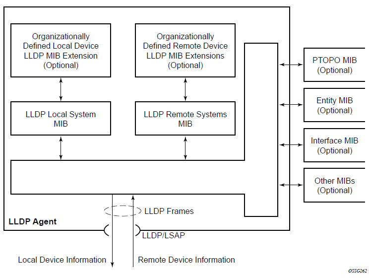
The following figure shows the internal architecture for a network node.
To detect and address network problems and inconsistencies in the configuration, the network operators can discover the topology information using LLDP. The Standard-based tools address the complex network scenarios where multiple devices from different vendors are interconnected using Ethernet interfaces.
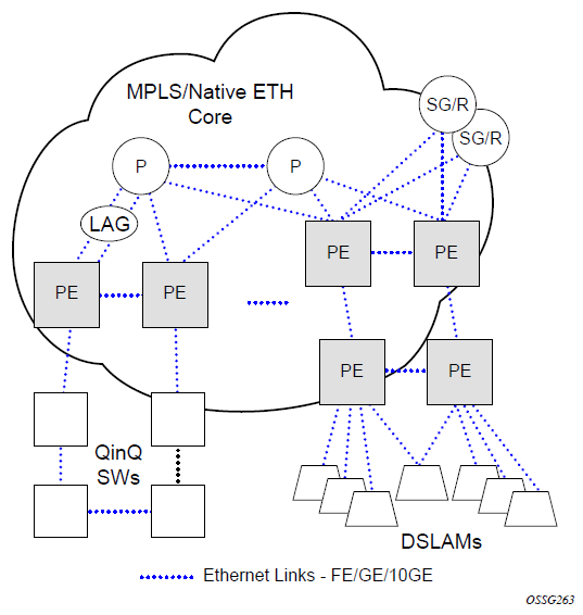
The following figure shows an MPLS network that uses Ethernet interfaces in the core or as an access/handoff interfaces to connect to different kind of Ethernet enabled devices such as service gateway/routers, QinQ switches DSLAMs or customer equipment.
The topology information of the network in the following figure can be discovered if, IEEE 802.1ab LLDP is running on each of the Ethernet interfaces in network.
LLDP protocol features
LLDP is an unidirectional protocol that uses the MAC layer to transmit specific information related to the capabilities and status of the local device. Separately from the transmit direction, the LLDP agent can also receive the same kind of information for a remote device which is stored in the related MIBs.
LLDP does not contain a mechanism for soliciting specific information from other LLDP agents, nor does it provide a specific means of confirming the receipt of information. LLDP allows the transmitter and the receiver to be separately enabled, making it possible to configure an implementation so the local LLDP agent can either transmit only or receive only, or can transmit and receive LLDP information.
The information fields in each LLDP frame are contained in a LLDP Data Unit (LLDPDU) as a sequence of variable length information elements, that each include type, length, and value fields (known as TLVs), where:
type identifies what kind of information is being sent
length indicates the length of the information string in octets
value is the actual information that needs to be sent (for example, a binary bit map or an alphanumeric string that can contain one or more fields)
Each LLDPDU contains four mandatory TLVs and can contain optional TLVs as selected by network management:
Chassis ID TLV
Port ID TLV
Time To Live TLV
Zero or more optional TLVs, as allowed by the maximum size of the LLDPDU
End Of LLDPDU TLV
The chassis ID and the port ID values are concatenated to form a logical identifier that is used by the recipient to identify the sending LLDP agent/port. Both the chassis ID and port ID values can be defined in a number of convenient forms. When selected however, the chassis ID/port ID value combination remains the same as long as the particular port remains operable.
A non-zero value in the TTL field of the Time To Live TLV tells the receiving LLDP agent how long all information pertaining to this LLDPDU identifier will be valid so that all the associated information can later be automatically discarded by the receiving LLDP agent if the sender fails to update it in a timely manner. A zero value indicates that any information pertaining to this LLDPDU identifier is to be discarded immediately.
Note that a TTL value of zero can be used, for example, to signal that the sending port has initiated a port shutdown procedure. The End Of LLDPDU TLV marks the end of the LLDPDU.
The implementation defaults to setting the port-id field in the LLDP OAMPDU to tx-local. This encodes the port-id field as ifIndex (sub-type 7) of the associated port. This is required to support some releases of SAM. SAM may use the ifIndex value to correctly build the Layer Two Topology Network Map. However, this numerical value is difficult to interpret or readily identify the LLDP peer when reading the CLI or MIB value without SAM. Including the port-desc option as part of the tx-tlv configuration allows an ALU remote peer supporting port-desc preferred display logic to display the value in the port description TLV instead of the port-id field value. This does not change the encoding of the port-id field. That value continues to represent the ifIndex. In some environments, it may be important to select the specific port information that is carried in the port-id field. The operator has the ability to control the encoding of the port-id information and the associated sub-type using the port-id-sub-type option. Three options are supported for the port-idsub-type:
tx-if-alias
Transmit the ifAlias String (sub-type 1) that describes the port as stored in the IFMIB, either user configured description or the default entry (ie 10/100/Gig Ethernet SFP)
tx-if-name
Transmits the ifName string (sub-type 5) that describes the port as stored in the IFMIB, ifName info
tx-local
The interface ifIndex value (sub-type 7)
IPv6 (address sub-type 2) and IPv4 (address sub-type 1) LLDP System Management addresses are supported.
LLDP tunneling for Epipe service
Customers who subscribe to Epipe service consider the Epipe as a wire, and run LLDP between their devices which are located at each end of the Epipe. To facilitate this, the 7210 SAS devices support tunneling of LLDP frames that use the nearest bridge destination MAC address.
If enabled using the command tunnel-nearest-bridge-dest-mac, all frames received with the matching LLDP destination MAC address are forwarded transparently to the remote end of the Epipe service. To forward these frames transparently, the port on which tunneling is enabled must be configured with NULL SAP and the NULL SAP must be configured in an Epipe service. Tunneling is not supported for any other port encapsulation or other services.
Additionally, before enabling tunneling, admin status for LLDP dest-mac nearest-bridge must be set to disabled or Tx only, using the command admin-status available under configure>port>ethernet>lldp>destmac-nearest-bridge. If admin-status for dest-mac nearest-bridge is set to receive and process nearest-bridge LLDPDUs (that is, if either rx or tx-rx is set) then it overrides the tunnel-nearest-bridge-dest-mac command.
The following table describes the behavior for LLDP with different values set in use for admin-status and when tunneling is enabled or disabled.
Nearest-bridge-mac admin status |
Tunneling enabled |
Tunneling disabled |
|---|---|---|
Rx |
Process/Peer |
Process/Peer |
Tx |
Tunnel |
Drop |
Rx-Tx |
Process/Peer |
Process/Peer |
Disabled |
Process/Peer |
Drop |
Transparent forwarding of LLDP frames can be achieved using the standard defined mechanism when using the either nearest-non-tmpr or the nearest-customer as the destination MAC address in the LLDP frames. Nokia recommends that the customers use these MAC address where possible to conform to standards. This command allows legacy LLDP implementations that do not support these additional destinations MAC addresses to tunnel LLDP frames that use the nearest-bridge destination MAC address.
LLDP media endpoint discovery
This feature is only supported on the 7210 SAS-Sx/S 1/10GE operating in the standalone or standalone-VC mode.
The IEEE standard 802.1AB is designed to provide a multivendor solution for the discovery of elements on an Ethernet Layer 2 data network. The LLDP standard allows nodes attached to an Ethernet LAN/WAN to advertise functionalities provided by that node to other nodes attached to the same LAN segment. See Link Layer Discovery Protocol for more information about IEEE 802.1AB.
The ANSI/TIA-1057 standard, Link Layer Discovery Protocol for Media Endpoint Devices, provides extensions to IEEE 802.1AB that are specific to media endpoint devices (MEDs), for example, voice phone and video terminal, in an IEEE 802 LAN environment. This standard defines specific usage of the IEEE 802.1AB LLDP base specification and interaction behavior between MEDs and LAN infrastructure elements.
LLDP media endpoint discovery (LLDP-MED) is an extension of LLDP that provides basic provisioning information to connected media endpoint devices. LLDP-MED extends LLDP protocol messages with more information to support voice over IP (VoIP) applications.
On the 7210 SAS, LLDP-MED supports the exchange of network policy information to provide the VLAN ID, dot1p bits, and IP DSCP value to media endpoint devices such as a VoIP phone.
The following TLVs are supported for LLDP-MED:
LLDP-MED Capabilities TLV
Network Policy TLV
LLDP-MED reference model
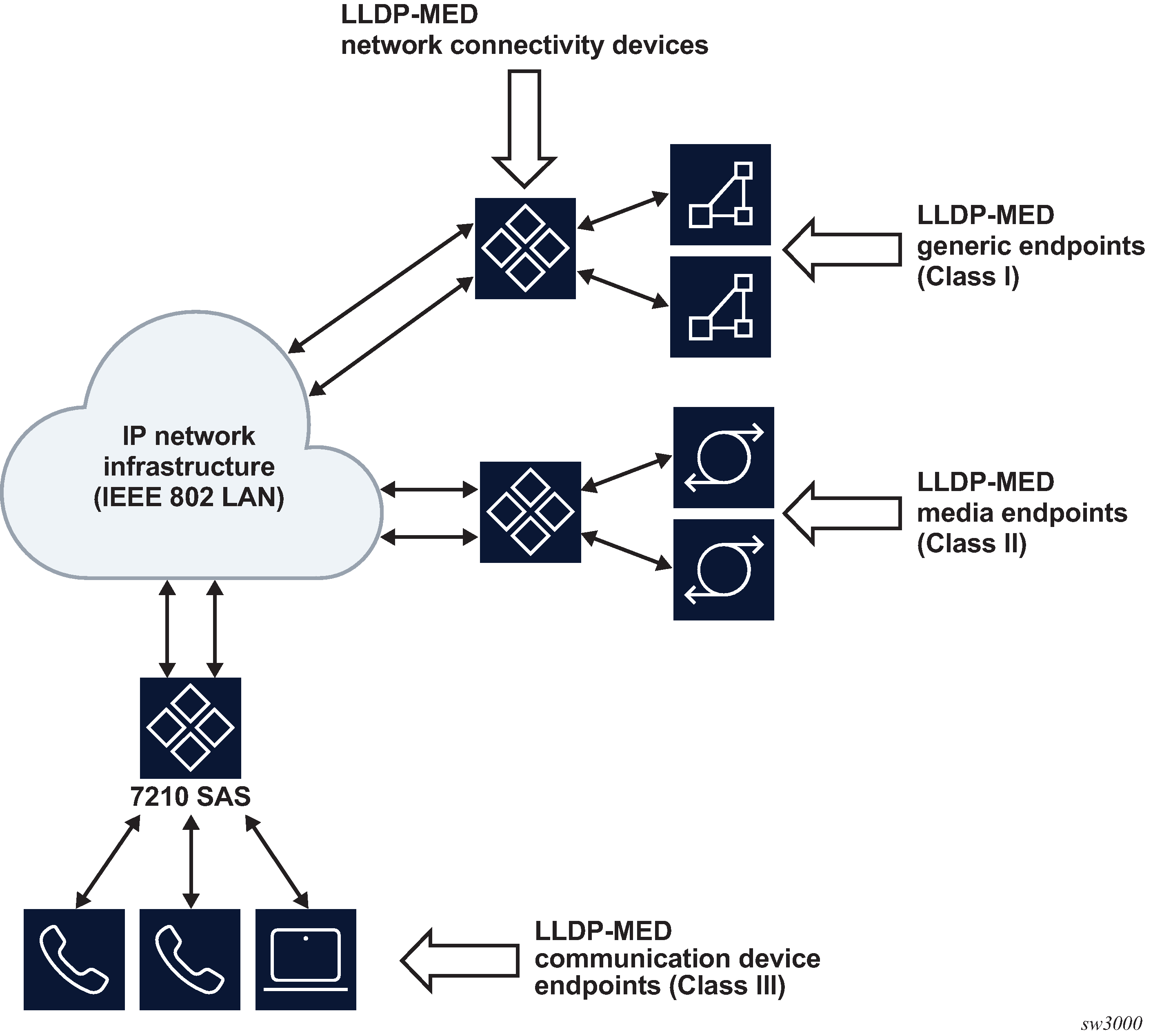
LLDP-MED devices are composed of two primary device types: network connectivity devices and endpoint devices.
LLDP-MED network connectivity devices provide access to the IEEE 802 LAN infrastructure for LLDP-MED endpoint devices. An LLDP-MED network connectivity device is a LAN access device based on any of the following technologies:
LAN switch or router
IEEE 802.1 bridge
IEEE 802.3 repeater
IEEE 802.11 wireless access point
any device that supports the IEEE 802.1AB and MED extensions defined by the standard and that can relay IEEE 802 frames using any method
Endpoint devices are composed of three sub-types, as defined in ANSI/TIA-1057:
generic endpoints (Class I)
This endpoint device class is for basic endpoints in LLDP-MED (for example, IP communications controllers).
media endpoints (Class II)
This endpoint device class supports IP media streams (for example, media gateways and conference bridges).
communication device endpoints (Class III)
This endpoint device class support the IP communication system end user (for example, IP telephones and softphones).
The following figure shows the LLDP-MED reference model.
Acting as the network connectivity device, the 7210 SAS only supports the configuration of LLDP-MED communication device endpoints (Class III), such as VoIP phone, using the Network Policy TLV.
LLDP-MED network connectivity device functions
To enable LLDP-MED network connectivity device functions, configure the config port ethernet lldp dest-mac lldp-med admin-status command. When this command is configured, the behavior of the node is as follows:
If admin-status is set to rx-tx, the LLDP agent transmits and receives LLDP-MED TLVs on the port. The 7210 SAS node includes the LLDP-MED Capabilities TLV and the Network Policy TLV (if configured) in the LLDP message that is generated in response to an LLDP message with the LLDP-MED Capabilities TLV received on the port.
If admin-status is set to disabled, the 7210 SAS ignores and does not process the LLDP-MED Capabilities TLV in the LLDP message received on the port.
The configure port ethernet lldp admin-status command must be enabled for LLDP-MED TLV processing. The admin-status configuration in the lldp context must not conflict with the admin-status configuration in the lldp-med context.
When LLDP-MED is enabled on the port, the Network Policy TLV is sent out of the port using the parameters configured for the network policy that is associated with the port.
See the 7210 SAS-Mxp, R6, R12, S, Sx, T Basic System Configuration Guide for more information about configuring network policy parameters using commands in the config>system>lldp>lldp-med context.
LLDP-MED endpoint device move notification
The endpoint move detection notification enables VoIP management systems to track the movement of VoIP phones. On the 7210 SAS, the user has the option to generate the lldpXMedTopologyChangeDetected event on detection of movement of the endpoint device. By default, the event is disabled. To enable the event, configure the config>log>event-control lldp generate and config>port>ethernet>lldp> dest-mac>nearest-bridge>notification commands.
Modified use of TLVs defined in LLDP
LLDP-MED modifies the usage of some LLDP base TLVs for network connectivity devices. Specifically, the 7210 SAS supports the transmission of the MAC/PHY Configuration Status TLV when LLDP-MED is enabled. The transmission of this TLV is enabled using the config>port>ethernet>lldp>dest-mac>lldp-med>tx-tlvs mac-phy-config-status CLI command option.
Port loopback for Ethernet ports
7210 SAS devices support port loopback for Ethernet ports. There are two flavors of port loopback commands - port loopback without mac-swap and port loopback with mac-swap. Both these commands are helpful for testing the service configuration and measuring performance parameters such as throughput, delay, and jitter on service turn-up. Typically, a third-party external test device is used to inject packets at desired rate into the service at a central office location.
The following sections describe the port loopback functionality.
Port loopback without MAC swap
When the port loopback command is enabled, the system enables PHY/MAC loopback on the specified port. All the packets are sent out the port configured for loopback and received back by the system. On ingress to the system after the loopback, the node processes the packets as per the service configuration for the SAP.
This is recommended for use with only VLL services. This command affects all the services configured on the port, therefore the user is advised to ensure all the configuration guidelines mentioned for this feature in the command description are followed.
Port loopback with MAC swap
Port loopback with MAC swap is not supported on100GE IMM-c cards for the 7210 SAS-R6 and 7210 SAS-R12.
The 7210 SAS provides port loop back support with MAC swap. When the port loopback command is enabled, the system enables PHY/MAC loopback on the specified port. All the packets are sent out the port configured for loopback and received back by the system. On ingress to the system after the loopback, the node swaps the MAC addresses for the specified SAP and the service. It only processes packets that match the specified source MAC address and destination MAC address, while dropping packets that do not match. It processes these packets as per the service configuration for the SAP.
This is recommended for use with only VPLS and VLL services. This command affects all the services configured on the port, therefore the user is advised to ensure all the configuration guidelines mentioned for this feature in the command description are followed.
LAG
Based on the IEEE 802.3ax standard (formerly 802.3ad), Link Aggregation Groups (LAGs) can be configured to increase the bandwidth available between two network devices, depending on the number of links installed. LAG also provides redundancy when one or more links participating in the LAG fail. All physical links in a specific LAG links combine to form one logical interface.
Packet sequencing must be maintained for any specific session. The hashing algorithm deployed by Nokia routers is based on the type of traffic transported to ensure that all traffic in a flow remains in sequence while providing effective load sharing across the links in the LAG.
LAGs must be statically configured or formed dynamically with Link Aggregation Control Protocol (LACP). The optional marker protocol described in IEEE 802.3ax is not implemented. LAGs can be configured on network and access ports.
For details on LAG scale per platform, contact your Nokia technical support representative.
LAG features
This section describes hardware and software LAG capabilities.
Hardware capabilities
The LAG load sharing is executed in hardware, which provides line rate forwarding for all port types.
Software capabilities
The Nokia solution conforms to the IEEE LAG implementation, including dynamic costing and LAG port threshold features. The dynamic cost and LAG port threshold features can be enabled even if the second node is not a Nokia router.
Dynamic cost
Dynamic cost can be enabled with the config>lag dynamic-costcommand or by the action specified in the config>lag>port-threshold command.
If dynamic cost is enabled and the number of active links is greater than the port threshold value (0-7 or 0-15), depending on chassis-mode and IOM type), then the path cost is dynamically calculated whenever there is a change in the number of active links regardless of the specified port threshold action. If the port-threshold is met and the action is set to dynamic cost, then the path cost is dynamically recalculated regardless of the global dynamic cost configuration.
Enabling dynamic costing causes the physical link metrics used by OSPF to be applied based on the operational or aggregate link bandwidth in the LAG that is available at the time, providing the number of links that are up exceeds the configured LAG port threshold value. If the number of available links falls below the configured threshold, the configured threshold action determines if and at what cost this LAG will be advertised.
For example, assume a single link in OSPF has an associated cost of 100 and the LAG consists of four physical links. The cost associated with the logical link is 25. If one link fails then the cost would automatically be adjusted to 33.
If dynamic cost is not configured then costing is applied based on the total number of links configured. The cost would be calculated at 25. This will remain static provided the number of links that are up exceeds the configured LAG threshold.
LAG port threshold
The LAG port threshold feature allows configuration of the behavior, when the number of available links in a LAG falls below or is equal to the specified threshold. Two options are available:
If the number of links available (up) in a LAG is less than the configured threshold, then the LAG is regarded as operationally down. For example, assume a LAG consists of four physical links. The threshold is set to two and dynamic costing is not configured. If the operational links is equal to or drops below two, the link is regarded as operationally down until the number of operational links is two or more.
When the number of links available in a LAG is less than the configured threshold, the LAG starts using the dynamic-cost allowing other nodes to adjust their routing tables according to the revised costs. In this case, when the threshold is not crossed, a fixed metric (all links operational) is advertised.
Configuring LAGs
The following are guidelines for configuring LAGs:
Ports can be added or removed from the LAG while the LAG and its ports (other than the port being removed) remain operational. When ports to or from the LAG are added or removed, the hashing algorithm is adjusted for the new port count.
The show commands display physical port statistics on a port-by-port basis or the entire LAG can be displayed.
LAG is supported on Ethernet ports.
Ports of a particular LAG can be of different types but they must be the same speed and duplex. To guarantee the same port speed is used for all ports in a LAG, auto-negotiation must be disabled or in limited mode to ensure only a specific speed is advertised.
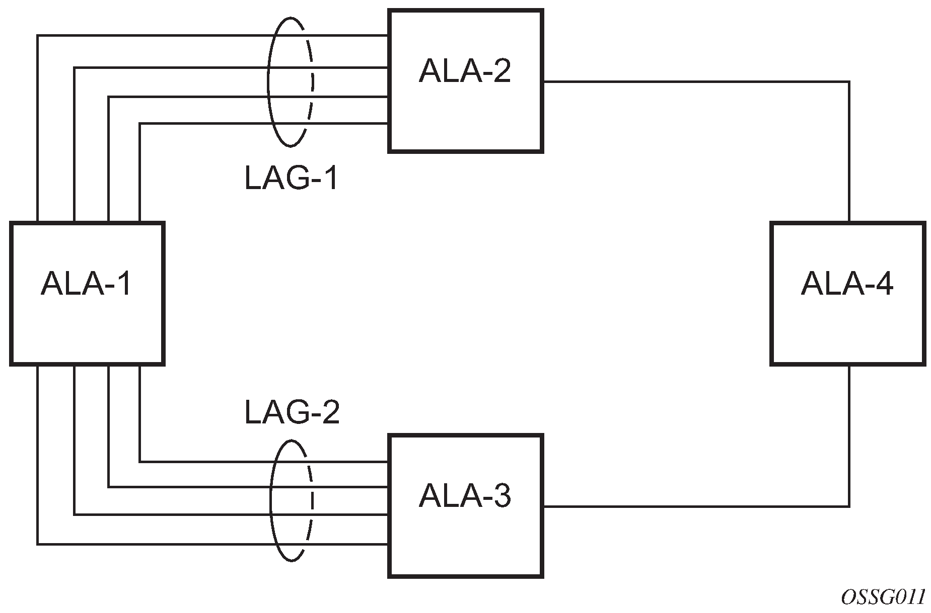
The following figure shows traffic routed between ALA-1 and ALA-2 as a LAG consisting of four ports.
LAG on access
Link Aggregation Groups (LAG) is supported on access ports and access-uplink ports. This is treated the same as LAG on network ports which provides a standard method to aggregate Ethernet links. The difference lies in how QoS is handled.
LAG and QoS policies on 7210 SAS-T, 7210 SAS-Sx/S 1/10GE, and 7210 SAS-Sx 10/100GE
In the 7210 SAS-T, 7210 SAS-Sx/S 1/10GE, and 7210 SAS-Sx 10/100GE an ingress QoS policy is applied to the aggregate traffic that is received on all the member ports of the LAG. For example, if an ingress policy is configured with a policer of PIR 100 Mbps, for a SAP configured on a LAG with two ports, then the policer limits the traffic received through the two ports to a maximum of 100 Mbps.
In the 7210 SAS-T, 7210 SAS-Sx/S 1/10GE, and 7210 SAS-Sx 10/100GE an egress QoS policy parameters are applied to all the ports that are members of the LAG (all ports get the full SLA). For example, if an egress policy is configured with a queue shaper rate of PIR 100 Mbps, and applied to an access-uplink or access LAG configured with two port members, then each port would send out 100 Mbps of traffic for a total of 200 Mbps of traffic out of the LAG. The advantage of this method over a scheme where the PIR is divided equally among all the member ports of the LAG is that, a single flow can use the entire SLA. The disadvantage is that, the overall SLA can be exceeded if the flows span multiple ports.
LAG and QoS policies on 7210 SAS-Mxp
In 7210 SAS-Mxp, a SAP ingress QoS policy or network port ingress QoS policy or network IP interface ingress QoS policy is applied to the aggregate traffic that enters the traffic through all the ports of the system. For example, if an ingress policy is configured with a policer of PIR 100 Mbps, for a SAP configured on a LAG with two ports, then the policer limits the traffic entering the system through the two ports to a maximum of 100 Mbps.
In 7210 SAS-Mxp, SAP egress QoS policy shaper parameters are applied to all the ports that are members of the LAG (all ports get the full SLA). For example, if an SAP egress policy is configured with a shaper of PIR 100 Mbps, each port would get a PIR of 100 Mbps. The advantage of this method over a scheme where the PIR is divided equally among all the member ports of the LAG is that, a single flow can uses the entire SLA. The disadvantage is that the overall SLA can be exceeded if the flows span multiple ports.
In 7210 SAS-Mxp, network port egress QoS policy shaper parameters are applied to all the ports that are members of the LAG (all ports get the full SLA). For example, if an network port egress policy is configured with a shaper of PIR 100 Mbps, each port would get a PIR of 100 Mbps. The advantage of this method over a scheme where the PIR is divided equally among all the member ports of the LAG is that, a single flow can uses the entire SLA. The disadvantage is that the overall SLA can be exceeded if the flows span multiple ports.
In 7210 SAS-Mxp, when operating in port-based queuing mode, the access egress QoS policy is applied to access ports and the policy parameters are applied to all the ports that are members of the LAG (all access ports get the full SLA). For example, if an access egress policy is configured with a shaper of PIR 100 Mbps, each port gets a PIR of 100 Mbps. The advantage of this method over a scheme where the PIR is divided equally among all the member ports of the LAG is that a single flow can use the entire SLA. The disadvantage is that the overall SLA can be exceeded if the flows span multiple ports. Access egress policy override parameters configured for the primary port of the LAG are applied to all the member ports of the LAG.
LAG and QoS policies on 7210 SAS-R6 and 7210 SAS-R12
In 7210 SAS-R6 and 7210 SAS-R12, a SAP ingress QoS policy or network port ingress QoS policy or network IP interface ingress QoS policy is applied to the aggregate traffic that enters through all the ports on a IMM. If the LAG has member ports on different IMMs, then the policy is created for each IMM and is applied to the aggregate traffic that enters through all the ports on a specific IMM. For example, if an ingress policy is configured with a policer of PIR 100 Mbps, for a SAP configured on a LAG with two ports, then the policer limits the traffic entering through the two ports of the IMM to a maximum of 100 Mbps. If the LAG has two ports on 2 different IMMs, then policy is applied each IMM individually, and the policer on each IMM allows a maximum of 100 Mbps for a total of 200 Mbps.
In 7210 SAS-R6 and 7210 SAS-R12, SAP egress QoS policy shaper parameters are applied to all the ports that are members of the LAG (all ports get the full SLA), irrespective of whether they are located on a single IMM or two different IMMs. For example, if an SAP egress policy is configured with a shaper of PIR 100 Mbps, each port would get a PIR of 100 Mbps. The advantage of this method over a scheme where the PIR is divided equally among all the member ports of the LAG is that, a single flow can uses the entire SLA. The disadvantage is that the overall SLA can be exceeded if the flows span multiple ports.
In 7210 SAS-R6 and 7210 SAS-R12, network port egress QoS policy shaper parameters are applied to all the ports that are members of the LAG (all ports get the full SLA), irrespective of whether they are located on a single IMM or two different IMMs. For example, if an network port egress policy is configured with a shaper of PIR 100 Mbps, each port would get a PIR of 100 Mbps. The advantage of this method over a scheme where the PIR is divided equally among all the member ports of the LAG is that, a single flow can uses the entire SLA. The disadvantage is that the overall SLA can be exceeded if the flows span multiple ports.
In 7210 SAS-R6 and 7210 SAS-R12, when operating in port-based queuing mode, the access egress QoS policy is applied to access ports and the policy parameters are applied to all the ports that are members of the LAG (all access ports get the full SLA). For example, if an access egress policy is configured with a shaper of PIR 100 Mbps, each port gets a PIR of 100 Mbps. The advantage of this method over a scheme where the PIR is divided equally among all the member ports of the LAG is that a single flow can use the entire SLA. The disadvantage is that the overall SLA can be exceeded if the flows span multiple ports. Access egress policy override parameters configured for the primary port of the LAG are applied to all the member ports of the LAG.
Port link damping
Hold time controls enable port link damping timers that reduce the number of link transitions reported to upper layer protocols.
The 7210 SAS OS port link damping feature guards against excessive port transitions. Any initial port transition is immediately advertised to upper layer protocols, but any subsequent port transitions are not advertised to upper layer protocols until a configured timer has expired.
An ‟up” timer controls the dampening timer for link up transitions, and a ‟down” timer controls the dampening timer for link down transitions.
LACP
Generally, link aggregation is used for two purposes: provide an increase in bandwidth and provide redundancy. Both aspects are addressed by aggregating several Ethernet links in a single LAG.
Under normal operation, all non-failing links in a specific LAG will become active and traffic is load balanced across all active links. In some circumstances, however, this is not wanted. Instead, it may be wanted that only some of the links are active and the other links be kept in stand-by condition.
LACP enhancements allow active lag-member selection based on particular constrains. The mechanism is based on the IEEE 802.3ax standard so interoperability is ensured.
Active-standby LAG operation without LACP
Active/standby LAG is used to provide redundancy while keeping consistency of QOS enforcement. Some devices do not support LACP and therefore an alternative solution is required.
The active/standby decision for LAG member links is local decision driven by preconfigured selection-criteria. This decision was communicated to remote system using LACP signaling.
As an alternative, the operator can disable the signal transmitted by using the power-off option for standby-signaling in the CLI command at the LAG level at the port member level. The transmit laser is switched off for all LAG members in standby mode. On switch over (active-links failed), the laser is switched on and all LAG members become active.
This mode of operation cannot detect physical failures on the standby link, which means that the network operator cannot be certain that the standby links are capable to take over in case of active-links failure. This is an inherent limitation of this operational mode.
When LACP goes down on a standby link, a warning message announcing that LACP has expired on the corresponding member port is printed in log 99 at the other end.
The operation where standby ports are powered down is mutually exclusive with LACP and, therefore, is modeled as a separate mode of LACP operation of power-off. For this mode, the best-port selection criteria can be used. This criteria ensures that a subgroup with the best-port (the highest priority port) is always chosen to be used as the active subgroup.
It is not possible to have an active LACP in the power-off mode before the correct selection criteria is selected.
LAG subgroups
LACP is used to make a selection of active links predictable and compatible with any vendor equipment. See IEEE STD 802.3-2002, Section 3, Clause 43.6.1, which describes how LACP allows standby and active signaling.
The 7210 SAS-T, 7210 SAS-R6, 7210 SAS-R6, 7210 SAS-Mxp, 7210 SAS-Sx/S 1/10GE (operating in standalone and standalone-VC mode), and 7210 SAS-Sx 10/100GE (operating in standalone mode) implementation of LACP supports the following:
A specific LAG member can be assigned to subgroups. The selection algorithm then assures that only members of a single subgroup are selected as active links.
The selection algorithm is effective only if LACP is enabled on a specific LAG. At the same time, it is assumed that the connected system also has LACP enabled (active or passive mode).
The algorithm selects active links based on following criteria:
Depending on the selection-criteria settings either the subgroup with the highest number of eligible links or the subgroup with the highest aggregate weight of all eligible members is selected first.
If multiple groups satisfy the selection criteria, the currently active subgroup remains active. Initially, the subgroup containing the highest priority eligible link is selected.
Only links pertaining to a single subgroup are active at any time.
An eligible member refers to a LAG member link that can potentially become active; that is, it is operationally up. If the slave-to-partner flag is set, the remote system does not disable its use (by signaling the ‟Standby” bit using LACP).
The selection algorithm works in a reverting mode. Each time the configuration or status of any link in a LAG changes, the selection algorithm is rerun. In case of a tie between two groups (one of them being currently active), the active group remains active (no reverting).
LAG and ECMP hashing
See the 7210 SAS-Mxp, R6, R12, S, Sx, T Router Configuration Guide for more information about ECMP support for 7210 SAS platforms.
When a requirement exists to increase the available bandwidth for a logical link that exceeds the physical bandwidth or add redundancy for a physical link, typically one of the methods is applied; equal cost multi-path (ECMP) or LAG. A 7210 SAS can deploy both at the same time, meaning, using ECMP of two or more LAGs or single links.The Nokia implementation supports per flow hashing used to achieve uniform loadspreading and per service hashing designed to provide consistent per service forwarding. Depending on the type of traffic that needs to be distributed into an ECMP or a LAG, different variables are used as input to the hashing algorithm.
An option is provided per LAG to select the hashing function to be used for load-balancing flows on the member ports of the LAG. Users can use one of the available options based on the flows they have in their network and select an option that helps improve the load-balancing of flows in their network. The packets fields selected by the hashing function is different for some flows with the two hashing functions and is provided in the following tables.
LAG hashing for the 7210 SAS-T (network mode)
The following table describes the packet fields used for hashing for services configured on the 7210 SAS-T in network mode.
The following notes apply to LAG hashing algorithm for services and traffic flows configured on the 7210 SAS-T configured in the network operating mode.
In the case of LSR, incoming labels are used for hashing.
The term ‟learned” corresponds to destination MAC.
The term ‟source and destination MAC” refers to customer source and destination MACs unless otherwise specified.
Traffic type |
Hashing options |
Packet fields used |
||||||||||||
|---|---|---|---|---|---|---|---|---|---|---|---|---|---|---|
|
Hash-1 |
Hash-2 |
BDA |
BSA |
CDA |
CSA |
EtherType |
Ingress Port-ID |
ISID |
MPLS label stack |
Source and destination |
VLAN |
|||
|
MAC |
IP |
L4 ports |
||||||||||||
VPLS service SAP to SAP |
||||||||||||||
IP traffic (learned) |
✓ |
✓ |
✓ |
|||||||||||
✓ |
✓ |
✓ |
✓ |
|||||||||||
IP traffic (unlearned) |
✓ |
✓ |
✓ |
✓ |
||||||||||
✓ |
✓ |
✓ |
✓ |
|||||||||||
PBB traffic (learned) |
✓ |
✓ |
✓ |
✓ |
||||||||||
✓ |
✓ |
✓ |
✓ |
✓ |
||||||||||
PBB traffic (unlearned) |
✓ |
✓ |
✓ |
✓ |
✓ |
|||||||||
✓ |
✓ |
✓ | ✓ |
✓ |
||||||||||
MPLS traffic (learned) |
✓ |
✓ 8 |
✓ |
|||||||||||
✓ |
✓ |
✓ 9 |
✓ |
|||||||||||
MPLS traffic (unlearned) |
✓ |
✓ |
✓ 9 |
✓ |
||||||||||
✓ |
✓ |
✓ 9 |
✓ |
|||||||||||
Non-IP traffic (learned) |
✓ |
✓ |
✓ |
✓ |
||||||||||
✓ |
✓ |
✓ | ✓ | ✓ |
||||||||||
Non-IP traffic (unlearned) |
✓ |
✓ |
✓ |
✓ |
✓ |
|||||||||
✓ |
✓ |
✓ |
✓ |
✓ |
||||||||||
VPLS service SAP to SDP |
||||||||||||||
IP traffic (learned) |
✓ |
✓ |
✓ |
|||||||||||
✓ |
✓ |
✓ |
✓ |
|||||||||||
IP traffic (unlearned) |
✓ |
✓ |
✓ |
✓ |
||||||||||
✓ |
✓ | ✓ |
✓ |
|||||||||||
PBB traffic (learned) |
✓ |
✓ |
✓ |
✓ |
||||||||||
✓ |
✓ |
✓ |
✓ |
✓ |
||||||||||
PBB traffic (unlearned) |
✓ |
✓ |
✓ |
✓ |
✓ |
|||||||||
✓ |
✓ |
✓ |
✓ |
✓ |
||||||||||
MPLS traffic (learned) |
✓ |
✓ |
✓ |
|||||||||||
✓ |
✓ |
✓ 9 |
✓ |
|||||||||||
MPLS traffic (unlearned) |
✓ |
✓ |
✓ 9 |
✓ |
||||||||||
✓ |
✓ |
✓ 9 |
✓ |
|||||||||||
Non-IP traffic (learned) |
✓ |
✓ |
✓ |
✓ |
||||||||||
✓ |
✓ |
✓ |
✓ |
✓ |
||||||||||
Non-IP traffic (unlearned) |
✓ |
✓ |
✓ |
✓ |
✓ |
|||||||||
✓ |
✓ |
✓ |
✓ |
✓ |
||||||||||
VPLS service SDP to SAP |
||||||||||||||
IP traffic (learned) |
✓ |
✓ 10 |
✓ |
✓ |
||||||||||
— |
||||||||||||||
PBB traffic (learned) |
✓ |
✓ 10 |
||||||||||||
— |
||||||||||||||
Non-IP traffic (learned) |
✓ |
✓ |
✓ 10 |
|||||||||||
— |
||||||||||||||
All traffic (learned) |
— |
|||||||||||||
✓ |
✓ |
✓ 10 |
||||||||||||
All traffic (unlearned) |
✓ |
✓ |
✓ 10 |
|||||||||||
✓ |
✓ |
✓ 10 |
||||||||||||
VPLS service SDP to SDP |
||||||||||||||
All traffic (learned) |
✓ |
✓ 10 |
||||||||||||
✓ |
✓ |
✓ 10 |
||||||||||||
All traffic (unlearned) |
✓ |
✓ |
✓ 10 |
|||||||||||
✓ |
✓ |
✓ 10 |
||||||||||||
Epipe service SAP to SAP |
||||||||||||||
IP traffic |
✓ |
✓ |
✓ |
|||||||||||
✓ |
✓ |
✓ |
✓ |
|||||||||||
PBB traffic |
✓ |
✓ |
✓ |
✓ |
||||||||||
✓ |
✓ |
✓ |
✓ |
✓ |
||||||||||
MPLS traffic |
✓ |
✓8 |
✓ |
|||||||||||
✓ |
✓ |
✓ 9 |
✓ |
|||||||||||
Non-IP traffic |
✓ |
✓ |
✓ |
✓ |
||||||||||
✓ |
✓ |
✓ |
✓ |
✓ |
||||||||||
Epipe service SAP to SDP |
||||||||||||||
IP traffic |
✓ |
✓ |
✓ |
|||||||||||
✓ |
✓ |
✓ |
✓ |
|||||||||||
PBB traffic |
✓ |
✓ |
✓ |
✓ |
||||||||||
✓ |
✓ |
✓ |
✓ |
✓ |
||||||||||
MPLS traffic |
✓ |
✓ |
✓ |
|||||||||||
✓ |
✓ |
✓ 9 |
✓ |
|||||||||||
Non-IP traffic |
✓ |
✓ |
✓ |
✓ |
||||||||||
✓ |
✓ |
✓ |
✓ |
✓ |
||||||||||
Epipe service SDP to SAP |
||||||||||||||
IP traffic |
✓ |
✓ 10 |
✓ |
✓ |
||||||||||
— |
||||||||||||||
PBB traffic |
✓ |
✓ 10 |
||||||||||||
— |
||||||||||||||
Non-IP traffic |
✓ |
✓ |
✓ 10 |
|||||||||||
— |
||||||||||||||
All traffic |
— |
|||||||||||||
✓ |
✓ |
✓ 10 |
||||||||||||
MPLS – LSR |
||||||||||||||
All traffic |
✓ |
✓ 8 |
||||||||||||
✓ |
✓ |
✓ 9 |
✓11 |
|||||||||||
PBB VPLS service B-SAP to B-SAP (PBB BCB traffic) |
||||||||||||||
IP traffic (learned) |
✓ |
✓ |
✓ |
|||||||||||
✓ |
✓ |
✓ |
✓ |
|||||||||||
IP traffic (unlearned) |
✓ |
✓ |
✓ |
✓ |
||||||||||
✓ |
✓ |
✓ |
✓ |
|||||||||||
L2 and non-IP traffic (learned) |
✓ |
✓ |
✓ |
|||||||||||
✓ |
✓ |
✓ |
✓ |
✓ |
||||||||||
L2 and non-IP traffic (unlearned) |
✓ |
✓ |
✓ |
✓ |
✓ |
|||||||||
✓ |
✓ |
✓ |
✓ |
✓ |
||||||||||
PBB VPLS service I-SAP to B-SAP (originating PBB BEB traffic) |
||||||||||||||
IP traffic (learned) |
✓ |
✓ |
✓ |
|||||||||||
✓ |
✓ |
✓ |
✓ |
|||||||||||
IP traffic (unlearned) |
✓ |
✓ |
✓ |
✓ |
||||||||||
✓ |
✓ |
✓ |
✓ |
|||||||||||
L2 and non-IP traffic (learned) |
✓ |
✓ |
✓ |
✓ |
✓ |
|||||||||
✓ |
✓ |
✓ |
✓ |
✓ |
✓ |
|||||||||
L2 and non-IP traffic (unlearned) |
✓ |
✓ |
✓ |
✓ |
✓ |
✓ |
||||||||
✓ |
✓ |
✓ |
✓ |
✓ |
✓ |
|||||||||
PBB VPLS service B-SAP to I-SAP (terminating PBB BEB traffic) |
||||||||||||||
IP traffic (learned) |
✓ |
✓ |
✓ |
|||||||||||
✓ |
✓ |
✓ |
✓ |
|||||||||||
IP traffic (unlearned) |
✓ |
✓ |
✓ |
✓ |
||||||||||
✓ |
✓ |
✓ |
✓ |
|||||||||||
L2 and non-IP traffic (learned) |
✓ |
✓ |
✓ |
✓ |
||||||||||
✓ |
✓ |
✓ |
✓ |
✓ |
||||||||||
L2 and non-IP traffic (unlearned) |
✓ |
✓ |
✓ |
✓ |
✓ |
|||||||||
✓ |
✓ |
✓ |
✓ |
✓ |
||||||||||
PBB Epipe service PBB Epipe I-SAP to B-SAP (originating PBB BEB traffic) |
||||||||||||||
IP traffic |
✓ |
✓ |
✓ |
✓ |
||||||||||
✓ |
✓ |
✓ |
✓ |
|||||||||||
L2 and non-IP traffic |
✓ |
✓ |
✓ |
✓ |
✓ |
✓ |
||||||||
✓ |
✓ |
✓ |
✓ |
✓ |
✓ |
|||||||||
PBB Epipe service PBB Epipe SAP to B-SAP (terminating PBB BEB traffic) |
||||||||||||||
IP traffic |
✓ |
✓ |
✓ |
|||||||||||
✓ |
✓ |
✓ |
||||||||||||
L2 and non-IP traffic |
✓ |
✓ |
✓ |
✓ |
||||||||||
✓ |
✓ |
✓ |
✓ |
|||||||||||
VPRN service SAP to SAP SAP to SDP SDP to SAP |
||||||||||||||
— |
✓ |
✓ |
✓ |
|||||||||||
✓ |
✓ |
✓ |
✓ |
|||||||||||
IES service (IPv4) IES SAP to IES SAP |
||||||||||||||
— |
✓ |
✓ |
✓ |
|||||||||||
✓ |
✓ |
✓ |
✓ |
|||||||||||
IES service (IPv4) IES SAP to IPv4 network port interface |
||||||||||||||
— |
✓ |
✓ |
✓ |
|||||||||||
✓ |
✓ |
✓ |
✓ |
|||||||||||
Network port IPv4 interface IPv4 network interface to IPv4 network interface |
||||||||||||||
— |
✓ |
✓ |
✓ |
|||||||||||
✓ |
✓ |
✓ |
✓ |
|||||||||||
Network port IPv6 interface IPv6 network interface to IPv6 network interface |
||||||||||||||
— |
✓ |
✓ 12 |
✓ |
|||||||||||
✓ |
✓ |
✓ 12 |
✓ |
|||||||||||
LAG hashing for the 7210 SAS-T (access-uplink mode)
The following table describes the packet fields used for hashing for services configured on the 7210 SAS-T in access-uplink mode.
The following notes apply to LAG hashing algorithm for services configured on the 7210 SAS-T in the access-uplink operating mode:
The term ‟Learned” corresponds to destination MAC.
Source/destination MAC refers to customer source/destination MACs unless otherwise specified.
VLAN ID is considered for Learned - PBB, MPLS, Non-IP traffic in VPLS service only for traffic ingressing at dot1q, Q.*, Q1.Q2 SAPs.
Only outer VLAN tag is used for hashing.
Traffic type |
Packet fields used |
|||||||||
|---|---|---|---|---|---|---|---|---|---|---|
|
BDA |
BSA |
EtherType |
Ingress Port-ID |
ISID |
MPLS Label Stack |
Source and destination |
VLAN |
|||
|
MAC |
IP |
L4 Ports |
||||||||
VPLS service SAP to SAP |
||||||||||
IP traffic (learned) |
✓ |
✓ |
||||||||
IP traffic (unlearned) |
✓ |
✓ |
✓ |
|||||||
PBB traffic (learned) |
✓ |
✓ |
||||||||
PBB traffic (unlearned) |
✓ |
✓ |
✓ |
✓ |
||||||
MPLS traffic (learned) |
✓13 |
|||||||||
IP MPLS traffic (unlearned) |
✓ |
✓14 |
✓ |
|||||||
L2 MPLS traffic (unlearned) |
✓ |
✓ 14 |
||||||||
Non-IP traffic (learned) |
✓ |
✓ |
✓ |
|||||||
Non-IP traffic (unlearned) |
✓ |
✓ |
✓ |
✓ |
||||||
Epipe service SAP to SAP |
||||||||||
IP traffic |
✓ |
✓ |
✓ |
|||||||
PBB traffic |
✓ |
✓ |
✓ |
✓ |
||||||
IP MPLS traffic |
✓ |
✓ 14 |
✓ |
|||||||
L2 MPLS traffic |
✓ |
✓ 14 |
||||||||
Non-IP traffic |
✓ |
✓ |
✓ |
✓ |
||||||
IES service (IPv4) IES SAP to IES SAP |
||||||||||
IPv4 unicast traffic |
✓ |
✓ |
||||||||
LAG Hashing for the 7210 SAS-R6 and 7210 SAS-R12
The following table describes the packet fields used for hashing for services configured on the 7210 SAS-R6 and 7210 SAS-R12.
The following notes apply to LAG hashing algorithm for services and traffic flows configured on the 7210 SAS-R6 and 7210 SAS-R12:
The term ‟service_id” refers to the service ID of the egressing VPLS, Epipe, IES, or VPRN service.
The term ‟lag_index” refers to the Lag-IfIndex of the egressing lag.
the terms ‟encap_value” and ‟service_vlan” are based on the inner and outer VLAN values of the egressing LAG SAP.
The term ‟sap_index” is a value assigned uniquely for each SAP internally.
Parameters used for LAG hashing are the same in both SAP egress queue mode (SAP-based egress scheduling) or port egress queue mode (port-based egress scheduling), unless otherwise specified.
The term ‟learned” corresponds to the destination MAC.
The term ‟source and destination MAC” refers to customer source and destination MACs, unless otherwise specified.
In the case of a LAG with two ports at egress, different ingress port IDs may result in the same hash index, which causes traffic to always get hashed to only one of the ports. Load balancing is expected to occur when there are more than 2 ports in the lag.
The term ‟mgid” is the multicast group ID and is a software-allocated number. A unique number is allocated for each Layer-2 multicast MAC address.
The 7210 SAS supports Layer-2 multicast in a VPLS service. A group of 32 multicast IP addresses map to a single Layer-2 multicast MAC address. The ‟mgid” parameter remains the same for all IP multicast addresses that map to the same Layer-2 multicast MAC address.
Traffic type |
Hashing options |
Packet fields used |
|||||||||||
|---|---|---|---|---|---|---|---|---|---|---|---|---|---|
|
Hash-1 Version 1 |
Hash-1 Version 2 |
Hash-2 |
BDA |
BSA |
EtherType |
Ingress Port-ID |
ISID |
MPLS Label Stack |
Source and destination |
VLAN |
|||
|
MAC |
IP |
L4 Ports |
|||||||||||
VPLS service SAP to SAP |
|||||||||||||
IP traffic (learned) |
✓ |
✓ |
✓ |
||||||||||
✓ |
✓ |
✓ |
|||||||||||
✓ |
✓ |
✓ |
✓ |
||||||||||
PBB traffic (learned) |
✓ |
✓ |
✓ |
✓ |
|||||||||
✓ |
✓ |
✓ |
✓ |
||||||||||
✓ |
✓ |
✓ |
✓ |
✓ |
|||||||||
MPLS traffic (learned) |
✓ |
✓ 15 |
✓ |
||||||||||
✓ |
✓ 15 |
✓ |
|||||||||||
✓ |
✓ |
✓ 16 |
|||||||||||
Non-IP traffic (learned) |
✓ |
✓ |
✓ |
✓ |
|||||||||
✓ |
✓ |
✓ |
✓ |
||||||||||
✓ |
✓ |
✓ |
✓ |
✓ |
|||||||||
All traffic (unlearned) |
See note 17 |
|
|
|
|
|
|
|
|
|
|
||
|
|
|
|
|
|
|
|
|
|
||||
|
|
|
|
|
|
|
|
|
|
||||
VPLS service SAP to SDP |
|||||||||||||
IP traffic (learned) |
✓ |
✓ |
✓ |
||||||||||
✓ |
✓ |
✓ |
|||||||||||
✓ |
✓ |
✓ |
✓ |
||||||||||
IP traffic (unlearned) |
✓ |
✓ |
✓ |
✓ |
|||||||||
✓ |
✓ |
✓ |
✓ |
||||||||||
✓ |
✓ |
✓ |
✓ |
||||||||||
PBB traffic (learned) |
✓ |
✓ |
✓ |
✓ |
|||||||||
✓ |
✓ |
✓ |
✓ |
||||||||||
✓ |
✓ |
✓ |
✓ |
✓ |
|||||||||
PBB traffic (unlearned) |
✓ |
✓ |
✓ |
✓ |
✓ |
||||||||
✓ |
✓ |
✓ |
✓ |
✓ |
|||||||||
✓ |
✓ |
✓ |
✓ |
✓ |
|||||||||
MPLS traffic (learned) |
✓ |
✓ |
✓ |
||||||||||
✓ |
✓ |
✓ |
|||||||||||
✓ |
✓ |
✓ 16 |
✓ 18 |
||||||||||
MPLS traffic (unlearned) |
✓ |
✓ |
✓ 16 |
✓ 18 |
|||||||||
✓ |
✓ |
✓ 16 |
✓ 18 |
||||||||||
✓ |
✓ |
✓ 16 |
✓ 18 |
||||||||||
Non-IP traffic (learned) |
✓ |
✓ |
✓ |
✓ |
|||||||||
✓ |
✓ |
✓ |
✓ |
||||||||||
✓ |
✓ |
✓ |
✓ |
✓ |
|||||||||
Non-IP traffic (unlearned) |
✓ |
✓ |
✓ |
✓ |
✓ |
||||||||
— |
|||||||||||||
✓ |
✓ |
✓ |
✓ |
✓ |
|||||||||
VPLS service SDP to SAP |
|||||||||||||
IP traffic (learned) |
✓ |
✓ 16 |
✓ |
✓ |
✓ |
||||||||
✓ |
✓ |
✓ |
|||||||||||
— |
|||||||||||||
All traffic, excluding IP traffic (learned) |
✓ |
✓ |
✓ 19 |
||||||||||
✓ |
✓ |
✓ 19 |
|||||||||||
— |
|||||||||||||
All traffic (learned) |
— |
||||||||||||
— |
|||||||||||||
✓ |
✓ |
✓ 19 |
|||||||||||
All traffic (unlearned) |
See note 17 |
|
|
|
|
|
|
|
|
|
|
||
|
|
|
|
|
|
|
|
|
|
||||
VPLS service SDP to SDP |
|||||||||||||
All traffic (learned) |
✓ |
✓ 19 |
|||||||||||
✓ |
✓ 19 |
||||||||||||
✓ |
✓ |
✓ 19 |
|||||||||||
All traffic (unlearned) |
✓ |
✓ |
✓ 19 |
||||||||||
✓ |
✓ |
✓ 19 |
|||||||||||
✓ |
✓ |
✓ 19 |
|||||||||||
Epipe service SAP to SAP |
|||||||||||||
IP traffic |
✓ |
✓ |
✓ |
||||||||||
✓ |
✓ |
✓ |
|||||||||||
✓ |
✓ |
✓ |
✓ |
||||||||||
PBB traffic |
✓ |
✓ |
✓ |
✓ |
|||||||||
✓ |
✓ |
✓ |
✓ |
||||||||||
✓ |
✓ |
✓ |
✓ |
✓ |
|||||||||
MPLS traffic |
✓ |
✓ 15 |
✓ |
||||||||||
✓ |
✓ 15 |
✓ |
|||||||||||
✓ |
✓ |
✓ 16 |
|||||||||||
Non-IP traffic |
✓ |
✓ |
✓ |
✓ |
|||||||||
✓ |
✓ |
✓ |
✓ |
||||||||||
✓ |
✓ |
✓ |
✓ |
✓ |
|||||||||
Epipe service SAP to SDP |
|||||||||||||
IP traffic |
✓ |
✓ |
✓ |
||||||||||
✓ |
✓ |
✓ |
|||||||||||
✓ |
✓ |
✓ |
✓ |
||||||||||
PBB traffic |
✓ |
✓ |
✓ |
✓ |
|||||||||
✓ |
✓ |
✓ |
✓ |
||||||||||
✓ |
✓ |
✓ |
✓ |
✓ |
|||||||||
MPLS traffic |
✓ |
✓ |
✓ |
||||||||||
✓ |
✓ |
✓ |
|||||||||||
✓ |
✓ |
✓ 16 |
✓ 18 |
||||||||||
Non-IP traffic |
✓ |
✓ |
✓ |
✓ |
|||||||||
✓ |
✓ |
✓ |
✓ |
||||||||||
✓ |
✓ |
✓ |
✓ |
✓ |
|||||||||
Epipe service SDP to SAP |
|||||||||||||
IP traffic |
✓ |
✓ 16 |
✓ |
✓ |
✓ |
||||||||
✓ |
✓ |
✓ |
|||||||||||
— |
|||||||||||||
All other traffic |
✓ |
✓ |
✓ 19 |
||||||||||
✓ |
✓ |
✓ 19 |
|||||||||||
— |
|||||||||||||
All traffic |
— |
||||||||||||
— |
|||||||||||||
✓ |
✓ |
✓ 19 |
|||||||||||
MPLS – LSR |
|||||||||||||
All traffic |
✓ |
✓ 15 |
|||||||||||
✓ |
✓ 15 |
||||||||||||
✓ |
✓ |
✓ 20 |
✓ 21 |
||||||||||
VPLS (Multicast traffic with IGMP snooping enabled) SAP to SAP SDP to SAP |
|||||||||||||
— |
See note 22 |
|
|
|
|
|
|
|
|
|
|
||
|
|
|
|
|
|
|
|
|
|
||||
|
|
|
|
|
|
|
|
|
|
||||
VPRN service SAP to SAP SAP to SDP SDP to SAP |
|||||||||||||
— |
✓ |
✓ |
✓ |
||||||||||
✓ |
✓ |
✓ |
|||||||||||
✓ |
✓ |
✓ |
✓ |
||||||||||
IES service (IPv4) IES SAP to IES SAP |
|||||||||||||
— |
✓ |
✓ |
✓ |
||||||||||
✓ |
✓ |
✓ |
|||||||||||
✓ |
✓ |
✓ |
✓ |
||||||||||
IES service (IPv4) IES SAP to IPv4 network port interface |
|||||||||||||
— |
✓ |
✓ |
✓ |
||||||||||
✓ |
✓ |
✓ |
|||||||||||
✓ |
✓ |
✓ |
✓ |
||||||||||
Network port IPv4 interface IPv4 network interface to IPv4 network interface |
|||||||||||||
— |
✓ |
✓ |
✓ |
||||||||||
✓ |
✓ |
✓ |
|||||||||||
✓ |
✓ |
✓ |
✓ |
||||||||||
Network port IPv6 interface IPv6 network interface to IPv6 network interface |
|||||||||||||
— |
✓ |
✓ 23 |
✓ |
||||||||||
✓ |
✓ 23 |
✓ |
|||||||||||
✓ |
✓ |
✓ 23 |
✓ |
||||||||||
LAG hashing for the 7210 SAS-Mxp
The following table describes the packet fields used for hashing for services configured on the 7210 SAS-Mxp.
The following notes apply to LAG hashing algorithm for services and traffic flows configured on the 7210 SAS-Mxp :
In the case of LSR, incoming labels are used for hashing.
The term ‟learned” corresponds to the destination MAC.
The term ‟source and destination MAC” refers to customer source and destination MACs unless otherwise specified.
The term ‟service_id” refers to the service ID of the egressing VPLS, Epipe, IES, or VPRN service.
The term ‟lag_index” refers to the Lag-IfIndex of the egressing lag.
The terms ‟encap_value” and ‟service_vlan” are based on the inner/outer VLAN values of the egressing LAG SAP.
The term ‟sap_index” is a value assigned uniquely for each SAP internally.
Parameters used for LAG hashing are the same in both SAP egress queue mode (SAP-based egress scheduling) or port egress queue mode (port-based egress scheduling mode), unless otherwise specified previously.
The term ‟mgid” is the multicast group ID and is a software-allocated number. A unique number is allocated for each Layer-2 multicast MAC address.
The 7210 SAS supports Layer-2 multicast in a VPLS service. A group of 32 multicast IP addresses map to a single Layer-2 multicast MAC address. The ‟mgid” parameter remains the same for all IP multicast addresses that map to the same Layer-2 multicast MAC address.
|
Traffic type |
Hashing options |
Packet fields used |
|||||||||||
|---|---|---|---|---|---|---|---|---|---|---|---|---|---|
|
Hash-1 Version 1 |
Hash-1 Version 2 |
Hash-2 |
BDA |
BSA |
EtherType |
Ingress Port-ID |
ISID |
MPLS Label Stack |
Source and destination |
VLAN |
|||
|
MAC |
IP |
L4 Ports |
|||||||||||
|
VPLS and Epipe services SAP to SAP |
|||||||||||||
|
IP traffic (VPLS learned and Epipe; port-based egress scheduling) |
✓ |
✓ |
✓ |
||||||||||
|
✓ |
✓ |
✓ |
|||||||||||
|
✓ |
✓ |
✓ |
✓ |
||||||||||
|
MPLS traffic (VPLS learned and Epipe; port-based egress scheduling) |
✓ |
✓ |
✓ |
||||||||||
|
✓ |
✓ |
✓ |
|||||||||||
|
✓ |
✓ |
✓ 24 |
|||||||||||
|
Non-IP traffic (VPLS learned and Epipe; port-based egress scheduling) |
✓ |
✓ |
✓ |
✓ |
|||||||||
|
✓ |
✓ |
✓ |
✓ |
||||||||||
|
✓ |
✓ |
✓ |
✓ |
✓ |
|||||||||
|
All traffic (learned and unlearned; SAP-based egress scheduling) |
See note 25 |
|
|
|
|
|
|
||||||
|
|
|
|
|
|
|
|
|
|
|
||||
|
|
|
|
|
|
|
|
|
|
|
||||
|
All traffic (VPLS unlearned; port-based egress scheduling) |
See note 25 |
|
|
|
|
|
|
|
|
|
|
||
|
|
|
|
|
|
|
|
|
|
|
||||
|
|
|
|
|
|
|
|
|
|
|
||||
|
VPLS service SAP to SDP |
|||||||||||||
|
IP traffic (learned; SAP-based and port-based egress sheduling) |
✓ |
✓ |
✓ |
||||||||||
|
✓ |
✓ |
✓ |
|||||||||||
|
✓ |
✓ |
✓ |
✓ |
||||||||||
|
IP traffic (unlearned; SAP-based and port-based egress sheduling) |
✓ |
✓ |
✓ |
✓ |
|||||||||
|
✓ |
✓ |
✓ |
✓ |
||||||||||
|
✓ |
✓ |
✓ |
✓ |
||||||||||
|
MPLS traffic (learned; SAP-based and port-based egress sheduling) |
✓ |
✓ |
✓ |
||||||||||
|
✓ |
✓ |
✓ |
|||||||||||
|
✓ |
✓ |
✓ 24 |
|||||||||||
|
MPLS traffic (unlearned; SAP-based and port-based egress sheduling) |
✓ |
✓ |
✓ 24 |
||||||||||
|
✓ |
✓ |
✓ 24 |
|||||||||||
|
✓ |
✓ |
✓ 24 |
|||||||||||
|
Non-IP traffic (learned; SAP-based and port-based egress sheduling) |
✓ |
✓ |
✓ |
✓ |
|||||||||
|
✓ |
✓ |
✓ |
✓ |
||||||||||
|
✓ |
✓ |
✓ |
✓ |
✓ |
|||||||||
|
Non-IP traffic (unlearned; SAP-based and port-based egress sheduling) |
✓ |
✓ |
✓ |
✓ |
✓ |
||||||||
|
✓ |
✓ |
✓ |
✓ |
✓ |
|||||||||
|
✓ |
✓ |
✓ |
✓ |
✓ |
|||||||||
|
Epipe service SAP to SDP |
|||||||||||||
|
IP traffic (SAP-based and port-based egress sheduling) |
✓ |
✓ |
✓ |
||||||||||
|
✓ |
✓ |
✓ |
|||||||||||
|
✓ |
✓ |
✓ |
✓ |
||||||||||
|
MPLS traffic (SAP-based and port-based egress sheduling) |
✓ |
✓ |
✓ |
||||||||||
|
✓ |
✓ |
✓ |
|||||||||||
|
✓ |
✓ |
✓ 24 |
|||||||||||
|
Non-IP traffic (SAP-based and port-based egress sheduling) |
✓ |
✓ |
✓ |
✓ |
|||||||||
|
✓ |
✓ |
✓ |
✓ |
||||||||||
|
✓ |
✓ |
✓ |
✓ |
✓ |
|||||||||
|
VPLS and Epipe services SDP to SAP |
|||||||||||||
|
All traffic (including VPLS learned and unlearned; SAP-based egress scheduling) |
See note 25 |
|
|
|
|
|
|
|
|
|
|
||
|
|
|
|
|
|
|
|
|
|
|
||||
|
|
|
|
|
|
|
|
|
|
|
||||
|
All traffic (VPLS unlearned; port-based egress scheduling) |
See note 25 |
|
|
|
|
|
|
|
|
|
|
||
|
|
|
|
|
|
|
|
|
|
|
||||
|
|
|
|
|
|
|
|
|
|
|
||||
|
All other traffic (VPLS learned and Epipe; port-based egress scheduling) |
✓ |
✓26 |
|||||||||||
|
✓ |
✓ |
✓ |
|||||||||||
|
✓ |
✓ |
✓26 |
|||||||||||
|
VPLS service SDP to SDP |
|||||||||||||
|
All traffic (learned; SAP-based and port-based egress sheduling) |
✓ |
✓26 |
|||||||||||
|
✓ |
✓26 |
||||||||||||
|
✓ |
✓ |
✓26 |
|||||||||||
|
All traffic (unlearned; SAP-based and port-based egress sheduling) |
✓ |
✓ |
✓26 |
||||||||||
|
✓ |
✓ |
✓26 |
|||||||||||
|
✓ |
✓ |
✓26 |
|||||||||||
|
MPLS – LSR |
|||||||||||||
|
All traffic (SAP-based and port-based egress sheduling) |
✓ |
✓26 |
|||||||||||
|
✓ |
✓26 |
||||||||||||
|
✓ |
✓ |
✓ 27 |
✓ 28 |
||||||||||
|
VPLS (Multicast traffic with IGMP snooping enabled) SAP to SAP SDP to SAP |
|||||||||||||
|
— (SAP-based and port-based egress sheduling) |
See note 29 |
|
|
|
|
|
|
|
|
|
|
||
|
|
|
|
|
|
|
|
|
|
|
||||
|
|
|
|
|
|
|
|
|
|
|
||||
|
VPRN service SAP to SAP SDP to SAP |
|||||||||||||
|
All traffic (SAP-based egress scheduling) |
See note 25 |
|
|
|
|
|
|
|
|
|
|
||
|
|
|
|
|
|
|
|
|
|
|
||||
|
|
|
|
|
|
|
|
|
|
|
||||
|
All traffic (Port-based egress scheduling) |
✓ |
✓ |
✓ |
||||||||||
|
✓ |
✓ |
✓ |
|||||||||||
|
✓ |
✓ |
✓ |
✓ |
||||||||||
|
VPRN service SAP to SDP |
|||||||||||||
|
All traffic (SAP-based and port-based egress sheduling) |
✓ |
✓ |
✓ |
||||||||||
|
✓ |
✓ |
✓ |
|||||||||||
|
✓ |
✓ |
✓ |
✓ |
||||||||||
|
IES service (IPv4) IES SAP to IES SAP |
|||||||||||||
|
All traffic (SAP-based egress scheduling) |
See note 25 |
|
|
|
|
|
|
|
|
|
|
||
|
|
|
|
|
|
|
|
|
|
|
||||
|
|
|
|
|
|
|
|
|
|
|
||||
|
All traffic (Port-based egress scheduling) |
✓ |
✓ |
✓ |
||||||||||
|
✓ |
✓ |
✓ |
|||||||||||
|
✓ |
✓ |
✓ |
✓ |
||||||||||
|
IES service (IPv4) IES SAP to IPv4 network port interface |
|||||||||||||
|
— (SAP-based and port-based egress sheduling) |
✓ |
✓ |
✓ |
||||||||||
|
✓ |
✓ |
✓ |
|||||||||||
|
✓ |
✓ |
✓ |
✓ |
||||||||||
|
Network port IPv4 interface IPv4 network interface to IPv4 network interface |
|||||||||||||
|
— (SAP-based and port-based egress sheduling) |
✓ |
✓ |
✓ |
||||||||||
|
✓ |
✓ |
✓ |
|||||||||||
|
✓ |
✓ |
✓ |
✓ |
||||||||||
|
Network port IPv6 interface IPv6 network interface to IPv6 network interface |
|||||||||||||
|
— (SAP-based and port-based egress sheduling) |
✓ |
✓ |
✓ |
||||||||||
|
✓ |
✓ |
✓ |
|||||||||||
|
✓ |
✓ |
✓ |
✓ |
||||||||||
LAG hashing algorithm for the 7210 SAS-Sx/S 1/10GE and 7210 SAS-Sx 10/100GE in standalone and standalone-VC mode
The following table describes the packet fields used for hashing for services configured on the 7210 SAS-Sx/S 1/10GE and 7210 SAS-Sx 10/100GE operating in the standalone and standalone-VC modes.
The following terms are use in LAG hashing algorithm for services and traffic flows configured on the 7210 SAS-Sx/S 1/10GE and 7210 SAS-Sx 10/100GE in standalone and standalone-VC Mode:
The term ‟learned” corresponds to the destination MAC.
The term ‟source and destination MAC” refers to the customer source and destination MACs unless otherwise specified.
Traffic type |
Hashing options |
Packet fields used |
|||||||||||
|---|---|---|---|---|---|---|---|---|---|---|---|---|---|
|
Hash-1 Version 1 |
Hash-1 Version 2 |
Hash-2 |
BDA |
BSA |
EtherType |
Ingress Port-ID |
ISID |
MPLS Label Stack |
Source and destination |
VLAN |
|||
|
MAC |
IP |
L4 Ports |
|||||||||||
VPLS service SAP to SAP |
|||||||||||||
IP traffic (learned) |
✓ |
✓ |
✓ |
||||||||||
✓ |
✓ |
✓ |
|||||||||||
✓ |
✓ |
✓ |
✓ |
||||||||||
IP traffic (unlearned) |
✓ |
✓ |
✓ |
✓ |
|||||||||
✓ |
✓ |
✓ |
✓ |
||||||||||
✓ |
✓ |
✓ |
✓ |
||||||||||
PBB traffic (learned) |
✓ |
✓ |
✓ |
✓ |
✓ |
||||||||
✓ |
✓ |
✓ |
✓ |
✓ |
|||||||||
✓ |
✓ |
✓ |
✓ |
✓ |
✓ |
||||||||
PBB traffic (unlearned) |
✓ |
✓ |
✓ |
✓ |
✓ |
✓ |
|||||||
✓ |
✓ |
✓ |
✓ |
✓ |
✓ |
||||||||
✓ |
✓ |
✓ |
✓ |
✓ |
✓ |
||||||||
MPLS traffic (learned) |
✓ |
✓ |
✓ 30 |
✓ |
|||||||||
✓ |
✓ |
✓ 30 |
✓ |
||||||||||
✓ |
✓ |
✓ 31 |
✓ 32 |
||||||||||
MPLS traffic (unlearned) |
✓ |
✓ |
✓ 31 |
✓ 32 |
|||||||||
✓ |
✓ |
✓ 31 |
✓ 32 |
||||||||||
✓ |
✓ |
✓ 31 |
✓ 32 |
||||||||||
Non-IP traffic (learned) |
✓ |
✓ |
✓ |
✓ |
|||||||||
✓ |
✓ |
✓ |
✓ |
||||||||||
✓ |
✓ |
✓ |
✓ |
✓ |
|||||||||
Non-IP traffic (unlearned) |
✓ |
✓ |
✓ |
✓ |
✓ |
||||||||
✓ |
✓ |
✓ |
✓ |
✓ |
|||||||||
✓ |
✓ |
✓ |
✓ |
✓ |
|||||||||
Epipe service SAP to SAP |
|||||||||||||
IP traffic |
✓ |
✓ |
✓ |
||||||||||
✓ |
✓ |
✓ |
|||||||||||
✓ |
✓ |
✓ |
✓ |
||||||||||
PBB traffic |
✓ |
✓ |
✓ |
✓ |
✓ |
||||||||
✓ |
✓ |
✓ |
✓ |
✓ |
|||||||||
✓ |
✓ |
✓ |
✓ |
✓ |
✓ |
||||||||
MPLS traffic |
✓ |
✓ |
✓ 30 |
✓ |
|||||||||
✓ |
✓ |
✓ 30 |
✓ |
||||||||||
✓ |
✓ |
✓ 31 |
✓ 32 |
||||||||||
Non-IP traffic |
✓ |
✓ |
✓ |
✓ |
|||||||||
✓ |
✓ |
✓ |
✓ |
||||||||||
✓ |
✓ |
✓ |
✓ |
✓ |
|||||||||
VPLS service SAP to SDP |
|||||||||||||
IP traffic (learned) |
✓ |
✓ |
✓ |
||||||||||
✓ |
✓ |
✓ |
|||||||||||
✓ |
✓ |
✓ |
✓ |
||||||||||
IP traffic (unlearned) |
✓ |
✓ |
✓ |
✓ |
|||||||||
✓ |
✓ |
✓ |
✓ |
||||||||||
✓ |
✓ |
✓ |
✓ |
||||||||||
PBB traffic (learned) |
✓ |
✓ |
✓ |
✓ |
|||||||||
✓ |
✓ |
✓ |
✓ |
||||||||||
✓ |
✓ |
✓ |
✓ |
✓ |
✓ |
||||||||
PBB traffic (unlearned) |
✓ |
✓ |
✓ |
✓ |
✓ |
✓ |
|||||||
✓ |
✓ |
✓ |
✓ |
✓ |
✓ |
||||||||
✓ |
✓ |
✓ |
✓ |
✓ |
✓ |
||||||||
MPLS traffic (learned) |
✓ |
✓ |
✓ |
||||||||||
✓ |
✓ |
✓ |
|||||||||||
✓ |
✓ |
✓ 31 |
✓ 32 |
||||||||||
MPLS traffic (unlearned) |
✓ |
✓ |
✓ 31 |
✓ 32 |
|||||||||
✓ |
✓ |
✓ 31 |
✓ 32 |
||||||||||
✓ |
✓ |
✓ 31 |
✓ 32 |
||||||||||
Non-IP traffic (learned) |
✓ |
✓ |
✓ |
✓ |
|||||||||
✓ |
✓ |
✓ |
✓ |
||||||||||
✓ |
✓ |
✓ |
✓ |
✓ |
|||||||||
Non-IP traffic (unlearned) |
✓ |
✓ |
✓ |
✓ |
✓ |
||||||||
✓ |
✓ |
✓ |
✓ |
✓ |
|||||||||
✓ |
✓ |
✓ |
✓ |
✓ |
|||||||||
Epipe service SAP to SDP |
|||||||||||||
IP traffic |
✓ |
✓ |
✓ |
||||||||||
✓ |
✓ |
✓ |
|||||||||||
✓ |
✓ |
✓ |
✓ |
||||||||||
PBB traffic |
✓ |
✓ |
✓ |
✓ |
|||||||||
✓ |
✓ |
✓ |
✓ |
||||||||||
✓ |
✓ |
✓ |
✓ |
✓ |
✓ |
||||||||
MPLS traffic |
✓ |
✓ |
✓ |
||||||||||
✓ |
✓ |
✓ |
|||||||||||
✓ |
✓ |
✓ 31 |
✓ 32 |
||||||||||
Non-IP traffic |
✓ |
✓ |
✓ |
✓ |
|||||||||
✓ |
✓ |
✓ |
✓ |
||||||||||
✓ |
✓ |
✓ |
✓ |
✓ |
|||||||||
VPLS service SDP to SAP |
|||||||||||||
IP traffic (learned) |
✓ 33 |
✓ 34 |
✓ |
✓ |
✓ |
||||||||
✓ 33 |
✓ |
✓ |
|||||||||||
— |
|||||||||||||
PBB traffic (learned) |
✓ |
✓ |
✓ |
✓ |
|||||||||
✓ |
✓ |
✓ |
✓ |
||||||||||
— |
|||||||||||||
Non-IP traffic (learned) |
✓ 35 |
✓ |
✓ |
||||||||||
✓ 35 |
✓ |
✓ |
|||||||||||
— |
|||||||||||||
All traffic (learned) |
— |
||||||||||||
— |
|||||||||||||
✓ |
✓ |
✓ 36 |
|||||||||||
All traffic (unlearned) |
✓ |
✓ |
✓ 36 |
||||||||||
✓ |
✓ |
✓ 36 |
|||||||||||
✓ |
✓ |
✓ 36 |
|||||||||||
Epipe service SDP to SAP |
|||||||||||||
IP traffic |
✓ 33 |
✓ 34 |
✓ |
✓ |
✓ |
||||||||
✓ 33 |
✓ |
✓ |
|||||||||||
— |
|||||||||||||
PBB traffic |
✓ |
✓ |
✓ |
✓ |
|||||||||
✓ |
✓ |
✓ |
✓ |
||||||||||
— |
|||||||||||||
Non-IP traffic |
✓ 35 |
✓ |
✓ |
||||||||||
✓ 35 |
✓ |
✓ |
|||||||||||
— |
|||||||||||||
All traffic |
— |
||||||||||||
— |
|||||||||||||
✓ |
✓ |
✓ 36 |
|||||||||||
VPLS service SDP to SDP |
|||||||||||||
All traffic (learned) |
✓ |
✓ 36 |
|||||||||||
✓ |
✓ 36 |
||||||||||||
✓ |
✓ |
✓ 36 |
|||||||||||
All traffic (unlearned) |
✓ |
✓ |
✓ 36 |
||||||||||
✓ |
✓ |
✓ 36 |
|||||||||||
✓ |
✓ |
✓ 36 |
|||||||||||
MPLS – LSR |
|||||||||||||
All traffic |
✓ |
✓ 30 |
|||||||||||
✓ |
✓ 30 |
||||||||||||
✓ |
✓ |
✓ 31 |
✓ 37 |
||||||||||
VPLS IGMP snooping VPLS (Multicast traffic with IGMP snooping enabled): SAP to SAP SAP to SDP |
|||||||||||||
IP multicast traffic |
✓ |
✓ |
✓ |
✓ |
|||||||||
✓ |
✓ |
✓ |
✓ |
||||||||||
✓ |
✓ |
✓ |
✓ |
||||||||||
L2 multicast traffic |
✓ |
✓ |
✓ |
✓ |
|||||||||
✓ |
✓ |
✓ |
✓ |
||||||||||
✓ |
✓ |
✓ |
✓ |
||||||||||
VPLS IGMP snooping VPLS (Multicast traffic with IGMP snooping enabled): SDP to SAP, SDP to SDP |
|||||||||||||
— |
✓ |
✓ |
✓ |
||||||||||
✓ |
✓ |
✓ |
|||||||||||
✓ |
✓ |
✓ |
|||||||||||
VPRN service SAP to SAP SAP to SDP SDP to SAP |
|||||||||||||
— |
✓ |
✓ |
✓ |
||||||||||
✓ |
✓ |
✓ |
|||||||||||
✓ |
✓ |
✓ |
✓ |
||||||||||
IES service (IPv4): IES SAP to IES SAP |
|||||||||||||
— |
✓ |
✓ |
✓ |
||||||||||
✓ |
✓ |
✓ |
|||||||||||
✓ |
✓ |
✓ |
✓ |
||||||||||
IES service (IPv4): IES SAP to IPv4 network port interface |
|||||||||||||
— |
✓ |
✓ |
✓ |
||||||||||
✓ |
✓ |
✓ |
|||||||||||
✓ |
✓ |
✓ |
✓ |
||||||||||
Network port IPv4 interface: IPv4 network interface to IPv4 network interface |
|||||||||||||
— |
✓ |
✓ |
✓ |
||||||||||
✓ |
✓ |
✓ |
|||||||||||
✓ |
✓ |
✓ |
✓ |
||||||||||
Network port IPv6 interface: IPv6 network interface to IPv6 network interface |
|||||||||||||
— |
✓ |
✓ 38 |
✓ |
||||||||||
✓ |
✓ 38 |
✓ |
|||||||||||
✓ |
✓ |
✓ 38 |
✓ |
||||||||||
PW hash-label generation for 7210 SAS-R6 and 7210 SAS-R12
The following table describes the packet fields used to generate the hash label for different services and traffic types.
The following notes apply to Packet fields used for PW hash-label generation on the 7210 SAS-R6 and 7210 SAS-R12:
Source and destination MAC addresses are from the outermost Ethernet header.
MPLS and PBB traffic always use a fixed hash value. MPLS and PBB traffic encapsulation is identified by the system, only if the outermost Ethernet has two or fewer VLAN tags. If there are more VLAN tags, the system identifies the traffic as ‟Any other traffic”.
For IP traffic with two or more VLAN tags, source and destination MAC and VLAN are used to generate the hash label.
Any other traffic with three or more VLAN tags uses source and destination MAC and VLAN to generate the hash label.
The value of a hash label generated for the packet is the same and is not influenced by the configuration of the load-balancing algorithm using the command configure>lag>load-balancing.
Traffic identified as ‟All Other Traffic” have Ethertype or may not have Ethertype (for example, xSTP traffic does not have Ethertype). Ethertype is used only if available in the outermost Ethernet header for packets with two or fewer VLAN tags.
Traffic type |
Packet fields used |
|||||
|---|---|---|---|---|---|---|
|
EtherType |
Fixed Label Value |
Source and destination |
VLAN |
|||
|
MAC |
IP |
L4 Ports |
||||
VPLS and Epipe services SAP to SDP |
||||||
IP traffic |
✓ |
✓ |
||||
PBB traffic |
✓ |
|||||
MPLS traffic |
✓ |
|||||
Any other traffic |
✓ |
✓ |
✓ |
|||
VPLS service SDP to SDP |
||||||
IP traffic |
✓ |
✓ |
||||
PBB traffic |
✓ |
|||||
MPLS traffic |
✓ |
|||||
Any other traffic |
✓ |
✓ 39 |
✓ |
|||
PW hash-label – packet fields used for PW Hash-label generation for 7210 SAS-Mxp
The following table describes the packet fields used for different services and different traffic types, to generate the hash-label.
The following notes apply to Packet fields used for PW hash-label generation on the 7210 SAS-Mxp :
Source and destination MAC addresses are from the outermost Ethernet header.
MPLS and PBB traffic encapsulation is identified by the system only if the outermost Ethernet header has two or fewer VLAN tags.
Any traffic with three or more VLAN tags uses source and destination MAC and VLAN to generate the hash label.
The value of the hash label generated for the packet is the same and is not influenced by the configuration of the load-balancing algorithm using the command configure>lag>load-balancing.
Traffic identified as ‟All other traffic” may or may not have the Ethertype packet field (for example: xSTP traffic does not have Ethertype). Ethertype is used only if available in the outermost Ethernet header for packets with two or fewer VLAN tags.
Traffic type |
Packet fields used |
|||||||||
|---|---|---|---|---|---|---|---|---|---|---|
|
BDA |
BSA |
EtherType |
Ingress Port-ID |
ISID |
MPLS Label Stack |
Source and destination |
VLAN |
|||
|
MAC |
IP |
L4 Ports |
||||||||
VPLS and Epipe services SAP to SDP |
||||||||||
IP traffic |
✓ |
✓ |
✓ |
|||||||
PBB traffic |
✓ |
✓ |
✓ |
✓ |
||||||
MPLS traffic |
✓ |
✓ 40 |
✓ 41 |
|||||||
All other traffic |
✓ |
✓ |
✓ |
✓ |
||||||
VPLS service SDP to SDP |
||||||||||
All traffic |
✓ |
✓ 42 |
||||||||
PW Hash-label – packet fields used for PW hash-label generation for 7210 SAS-Sx/S 1/10GE
The following table describes the packet fields used for different services and different traffic types, to generate the hash-label.
The following notes apply to table Packet fields used for PW hash-label generation on the 7210 SAS-Sx/S 1/10GE :
Source and destination MAC addresses are from the outermost Ethernet header.
MPLS and PBB traffic encapsulation is identified by the system only if the outermost Ethernet has two or fewer VLAN tags.
Any traffic with three or more VLAN tags uses source and destination MAC and VLAN to generate the hash label.
The value of the hash label generated for the packet is the same and is not influenced by the configuration of the load-balancing algorithm using the command configure>lag>load-balancing.
Traffic identified as ‟All other traffic” may or may not have the Ethertype packet field (for example: xSTP traffic does not have Ethertype). Ethertype is used only if available in the outermost Ethernet header for packets with two or fewer VLAN tags.
Traffic type |
Packet fields used |
||||||
|---|---|---|---|---|---|---|---|
|
EtherType |
Ingress Port-ID |
MPLS Label Stack |
Source and destination |
VLAN |
|||
|
MAC |
IP |
L4 Ports |
|||||
VPLS and Epipe services SAP to SDP |
|||||||
IP traffic |
✓ |
✓ |
✓ |
||||
PBB traffic |
✓ |
||||||
MPLS traffic |
✓ |
✓ 43 |
✓ 44 |
||||
All other traffic |
✓ |
✓ |
✓ |
✓ |
|||
VPLS service SDP to SDP |
|||||||
All traffic |
✓ |
✓ 45 |
|||||
ECMP hashing for 7210 SAS devices in network mode
The following table describes the packet fields used for different services and different traffic types, to generate the hash-label.
Traffic type |
Packet fields used |
||||||
|---|---|---|---|---|---|---|---|
|
EtherType |
Ingress Port-ID |
MPLS Label Stack |
Source and destination |
VLAN |
|||
|
MAC |
IP |
L4 Ports |
|||||
Network port IPv4 interface |
|||||||
IPv4 traffic |
✓ |
✓ |
✓ |
||||
IES service SAP to SAP |
|||||||
IPv4 traffic |
✓ |
✓ |
✓ |
||||
Bidirectional Forwarding Detection over LAG links
The 7210 SAS-Mxp, 7210 SAS-R6, 7210 SAS-R12, 7210 SAS-T, and 7210 SAS-Sx/S 1/10GE and 7210 SAS-Sx 10/100GE operating in standalone mode support bidirectional forwarding detection (BFD) to monitor individual LAG link members, which speeds up the detection of link failures. When BFD is associated with an Ethernet LAG, BFD sessions are established over each link member; sessions are called micro-BFD (uBFD) sessions. A link is not operational in the associated LAG until the associated micro-BFD session is fully established. The link member is also removed from the operational state in the LAG if the BFD session fails.
If BFD over LAG links is configured before the LAG is active, a link will not become operational in the associated LAG until the associated BFD session is fully established. If a LAG link is already in a forwarding state when BFD over LAG links is enabled, the forwarding state of the LAG link is not influenced until the uBFD session is fully established. A setup timer is started to remove the link from the LAG in the case where the uBFD session is not set up in time. By default, the setup timer value is set to never expire.
When configuring the local and remote IP addresses for BFD over LAG link sessions, the local-ip parameter must match an IP address associated with the IP interface to which this LAG is bound. In addition, the remote-ip parameter must match an IP address on the remote system, and should also be in the same subnet as the local IP address. If the LAG bundle is reassociated with a different IP interface, the local-ip and remote-ip parameters should be modified to match the new IP subnet.
Configuration guidelines and restrictions for BFD over LAG links
The following guidelines apply for BFD over LAG links:
The local address used for BFD sessions over LAG links cannot be an IP interface address that is associated with R-VPLS services.
When a micro-BFD session is established, resources are allocated per member port of the LAG. These resources are taken from the pool that is used to map packets to SAPs. Therefore, adding ports to the LAG on which the micro-BFD session is configured reduces the number of SAPs.
When configuring a micro-BFD session with dot1q encapsulation, an IP interface with dot1q explicit null SAP (:0 SAP) must be configured on the port for the BFD session to be operational. The local IP address of the BFD session can inherit the IP address of the IP interface that is configured with dot1q explicit null SAP or any other IP interface with the LAG.
The local IP interface address used for micro-BFD sessions must match the address of an IP interface configured on the LAG. If an IP interface is configured with an encapsulation of dot1q explicit null SAP configured on the LAG (lag:0), the uBFD session is not established unless one of the following occurs:
The interface using lag:0 also has the same source IP address as the uBFD configuration.
There is an operationally up interface with the same source IP address in the same routing instance.
Micro-BFD sessions share the resources from the pool used to identify MAC addresses belonging to the node, and the sessions must be processed by the applications on the node. Establishing a micro-BFD session results in one less resource available for other applications that use the pool, such as an IP interface, which is explicitly configured with a MAC address. On the 7210 SAS-R6 and 7210 SAS-R12, the MAC address resource is allocated per card, and is only allocated on cards with a LAG member port configured.
A remote IP address configured for a micro-BFD session must be the same IP address used to configure the micro-BFD session in the peer node.
The local IP address configured for micro-BFD should belong to the same routing instance as the IP interface configured for :0 LAG.
Multi-chassis LAG
This section describes the Multi-Chassis LAG (MC-LAG) concept. MC-LAG is an extension of a LAG concept that provides node-level redundancy in addition to link-level redundancy provided by ‟regular LAG”.
MC-LAG is supported on all 7210 SAS platforms as described in this document, except those operating in access-uplink mode.
Typically, MC-LAG is deployed in a network-wide scenario and provides redundant connection between different end points. The whole scenario is then built by a combination of different mechanisms (for example, MC-LAG and redundant pseudowire to provide end-to-end (e2e) redundant point-to-point (p2p) connection or dual homing of CPE devices in Layer 2/3 VPNs).
The 7210 SAS platforms configured in access-uplink mode cannot peer with an MC-LAG-enabled node because it does not implement MC-LAG protocol; a 7210 SAS-T in access-uplink mode cannot provide MC-LAG server functionality. Instead they can be used as MC-LAG clients, with the platforms connected to a head-end node that support MC-LAG server functionality. These platforms connect to the head-end node using LAG.
Overview
MC-LAG is a method of providing redundant Layer 2/3 access connectivity that extends beyond link level protection by allowing two systems to share a common LAG end point.
The CPE/access node is connected with multiple links toward a redundant pair of Layer 2/3 access aggregation nodes such that both link and node level redundancy is provided. By using a multi-chassis LAG protocol, the paired Layer 2/3 aggregation nodes (referred to as the redundant-pair) appear to be a single node that is utilizing LACP toward the access node. The multi-chassis LAG protocol between the redundant-pair ensures a synchronized forwarding plane to and from the CPE/access node. It is used to synchronize the link state information between the redundant-pair nodes and provide correct LACP messaging to the CPE/access node from both redundant-pair nodes.
To ensure SLAs and deterministic forwarding characteristics between the CPE/access and the redundant-pair node, the multi-chassis LAG function provides an active/standby operation toward/from the CPE/access node. LACP is used to manage the available LAG links into active and standby states so that only links from one aggregation node are active at a time to and from the CPE/access node.
MC-LAG has the following characteristics:
Selection of the common system ID, system-priority, and administrative-key are used in LACP messages to ensure that partner systems consider all links part of the same LAG.
The selection algorithm is extended to allow the selection of the active subgroup.
The subgroup definition in the LAG context is still local to the single box. Consequently, even when subgroups configured on two different systems have the same subgroup-id, they are still considered two separate subgroups within the specific LAG.
The configuration of multiple subgroups per PE in an MC-LAG is supported.
If there is a tie in the selection algorithm, for example, two subgroups with identical aggregate weight (or number of active links), the group that is local to the system with lower system LACP priority and LAG system ID is selected.
Providing an inter-chassis communication channel allows the inter-chassis communication to support LACP on both systems. The communication channel enables the following functionality:
It supports connections at the IP level that do not require a direct link between two nodes. The IP address configured at the neighbor system is one of the addresses of the system (interface or loop-back IP address).
The communication protocol provides heartbeat mechanism to enhance robustness of the MC-LAG operation and detect node failures.
It supports operator actions that force an operational change on nodes.
The LAG group-ids do not have to match between neighbor systems. At the same time, multiple LAG groups between the same pair of neighbors is also allowed.
It verifies that the physical characteristics, such as speed and auto-negotiation are configured and initiates operator notifications (traps) if errors exist. Consistency of MC-LAG configuration (system-id, administrative-key and system-priority) is provided. Load-balancing must be consistently configured on both nodes.
Traffic over the signaling link is encrypted using a user-configurable message digest key.
The MC-LAG function provides active/standby status to other software applications to build reliable solutions.
MC-LAG L2 dual homing to remote PE pairs and MC-LAG L2 dual homing to local PE pairs show different combinations of supported MC-LAG attachments. The supported configurations can be divided into the following subgroups:
dual-homing to remote PE pairs
both end-points attached with MC-LAG
one end-point attached
dual-homing to local PE pair
both end-points attached with MC-LAG
one end-point attached with MC-LAG
both end-points attached with MC-LAG to two overlapping pairs
The following figure shows dual homing to remote PE pairs.
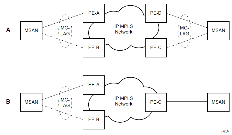
The following figure shows dual homing to local PE pairs.
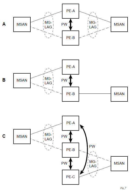
The forwarding behavior of the nodes is governed by the following principles. Note that the logical destination (actual forwarding decision) is primarily determined by the service (VPLS or VLL), and the following principle apply only if the destination or source is based on MC-LAG:
Packets received from the network will be forwarded to all local active links of the specific destination-sap based on conversation hashing. If there are no local active links, the packets will be cross-connected to the inter-chassis pseudowire.
Packets received from the MC-LAG sap will be forwarded to the active destination pseudowire or active local links of destination-sap. If no such objects are available at the local node, the packets will be cross-connected to inter-chassis pseudowire.
Point-to-point redundant connection across Layer 2/3 VPN network
The following figure shows the connection between two CPE/access nodes across network based on Layer 2/3 VPN pseudowires. The connection between a CPE/access node and a pair of access aggregation PE routers is realized by MC-LAG. From the CPE/access node perspective, a redundant pair of access aggregation PE routers acts as a single partner in LACP negotiation. At any point in time, only one of the routers has active links in a specific LAG. The status of LAG links is reflected in the status signaling of pseudowires set between all participating PEs. The combination of active and standby states across LAG links and pseudowires give only one unique path between a pair of MSANs.
Note that the configuration in the following figure shows an example configuration of VLL connections based on MC-LAG. Specifically, it shows a VLL connection where the two ends (SAPs) are located on two different redundant-pairs. However, additional configurations are possible, for example:
both ends of the same VLL connections are local to the same redundant-pair
one end of the VLL endpoint is on a redundant-pair and the other on a single (local or remote) node
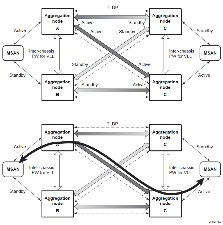
DSLAM dual homing in Layer 2 network
The following figure shows a network configuration where DSLAM is dual homed to a pair of redundant PEs by using MC-LAG. Inside the aggregation network, a redundant-pair of PEs is connecting to VPLS service, which provides a reliable connection to single or pair of Broadband Service Routers (BSRs).
PE-A and PE-B implement MC-LAG toward access. The active node synchronizes the IGMP snooping state with the standby node, allowing the standby node to forward multicast streams to receivers on the access side, if the active node fails.
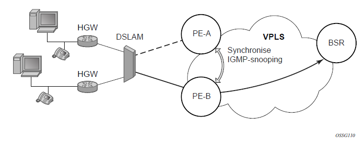
Configuration guidelines
The following guidelines apply to MC-LAG configurations:
MC-LAG peer nodes must be of the same platform type. For example, 7210 SAS-Sx/S 1/10GE can only peer with another 7210 SAS-Sx/S 1/10GE. 7210 SAS-Sx/S 1/10GE cannot be configured with 7210 SAS-Sx 10/100GE.
MC-LAG is only supported in network mode on 7210 SAS-T, 7210 SAS-Mxp, 7210 SAS-Sx/S 1/10GE, and 7210 SAS-Sx 10/100GE. For example, if two MC-LAG peers are set up using 7210 SAS-T, both need to be configured in network mode. It is not possible to have a node operating in network mode to be an MC-LAG peer with a node operating in access-uplink mode. This is true of standalone and standalone-VC modes, as well.
7210 SAS-T access-uplink mode supports active/standby LAG, which allows it to be used as client in an MC-LAG solution.
Configuring multi-chassis redundancy
When configuring associated LAG ID parameters, the LAG must be in access mode and LACP must be enabled.
Use the following syntax to configure multi-chassis redundancy features.
config>redundancy
  multi-chassis
     peer ip-address
        authentication-key [authentication-key | hash-key][hash | hash2]
        description description-string
        mc-lag
           hold-on-neighbor-failure duration
           keep-alive-interval interval
           lag lag-id lacp-key admin-key system-id system-id [remotelag lag-
id] system-priority system-priority
           no shutdown
        no shutdown
        source-address ip-address
        sync
           igmp-snooping
           port [port-id | lag-id] [sync-tag]range encap-range sync-tag
           no shutdown
config>redundancy# multi-chassis
config>redundancy>multi-chassis# peer 10.10.10.2 create
config>redundancy>multi-chassis>peer# description "Mc-Lag peer 10.10.10.2"
config>redundancy>multi-chassis>peer# mc-lag
config>redundancy>mc>peer>mc-lag# lag 1 lacp-key 32666 system-
id 00:00:00:33:33:33 system-priority 32888
config>redundancy>mc>peer>mc-lag# no shutdown
config>redundancy>mc>peer>mc-lag# exit
config>redundancy>multi-chassis>peer# no shutdown
config>redundancy>multi-chassis>peer# exit
config>redundancy>multi-chassis# exit
config>redundancy#
The following is a sample configuration output.
*7210-SAS>config>redundancy# info
----------------------------------------------
        multi-chassis
            peer 1.1.1.1 create
                shutdown
                sync
                    shutdown
                    port 1/1/1 create
                    exit
                exit
            peer 10.20.1.3 create
                mc-lag
                    lag 3 lacp-key 1 system-id 00:00:00:aa:bb:cc remote-
lag 1 system-priority 1
                    no shutdown
                exit
                no shutdown
            exit
        exit
----------------------------------------------
*7210-SAS>config>redundancy#
G.8032 protected Ethernet rings
Ethernet ring protection switching provides ITU-T G.8032 specification compliance to achieve resiliency for Ethernet Layer 2 networks. The G.8032 (Eth-ring) specification is built on Ethernet OAM and often referred to as Ring Automatic Protection Switching (R-APS).
See ‟G.8032 Ethernet Ring Protection Switching” in the 7210 SAS-Mxp, S, Sx, T Services Guide and the 7210 SAS-R6, R12 Services Guide.
802.1x network access control
The 7210 SAS supports network access control of client devices (PCs, STBs, and others) on an Ethernet network in accordance with the IEEE 802.1x standard (Extensible Authentication Protocol (EAP) over a LAN network or EAPOL).
Layer 2 control protocols affect 802.1x authentication behavior differently depending on the protocol in use; see Layer 2 control protocol interaction with authentication methods for more information.
802.1x modes
The 7210 SAS supports port-based network access control for Ethernet ports only. Every Ethernet port can be configured to operate in one of three different operation modes, controlled by the port-control parameter:
force-auth
Disables 802.1x authentication and causes the port to transition to the authorized state without requiring any authentication exchange. The port transmits and receives normal traffic without requiring 802.1x-based host authentication. This is the default setting.
force-unauth
Causes the port to remain in the unauthorized state, ignoring all attempts by the hosts to authenticate. The switch cannot provide authentication services to the host through the interface.
auto
Enables 802.1x authentication. The port starts in the unauthorized state, allowing only EAPOL frames to be sent and received through the port. Both the router and the host can initiate an authentication procedure, described as follows. The port will remain in an unauthorized state (no traffic except EAPOL frames is allowed) until the first client is authenticated successfully. After this, traffic is allowed on the port for all connected hosts.
802.1x basics
The IEEE 802.1x standard defines three participants in an authentication conversation:
supplicant
This is the end-user device that requests access to the network.
authenticator
This participant controls access to the network. Both the supplicant and the authenticator are referred to as Port Authentication Entities (PAEs).
authentication server
This participant performs the actual processing of the user information.
The authentication exchange is carried out between the supplicant and the authentication server, the authenticator acts only as a bridge. The communication between the supplicant and the authenticator is done through the Extended Authentication Protocol (EAP) over LANs (EAPOL). On the back end, the communication between the authenticator and the authentication server is done with the RADIUS protocol. The authenticator is therefore a RADIUS client, and the authentication server a RADIUS server.
The following figure shows the 802.1x architecture.
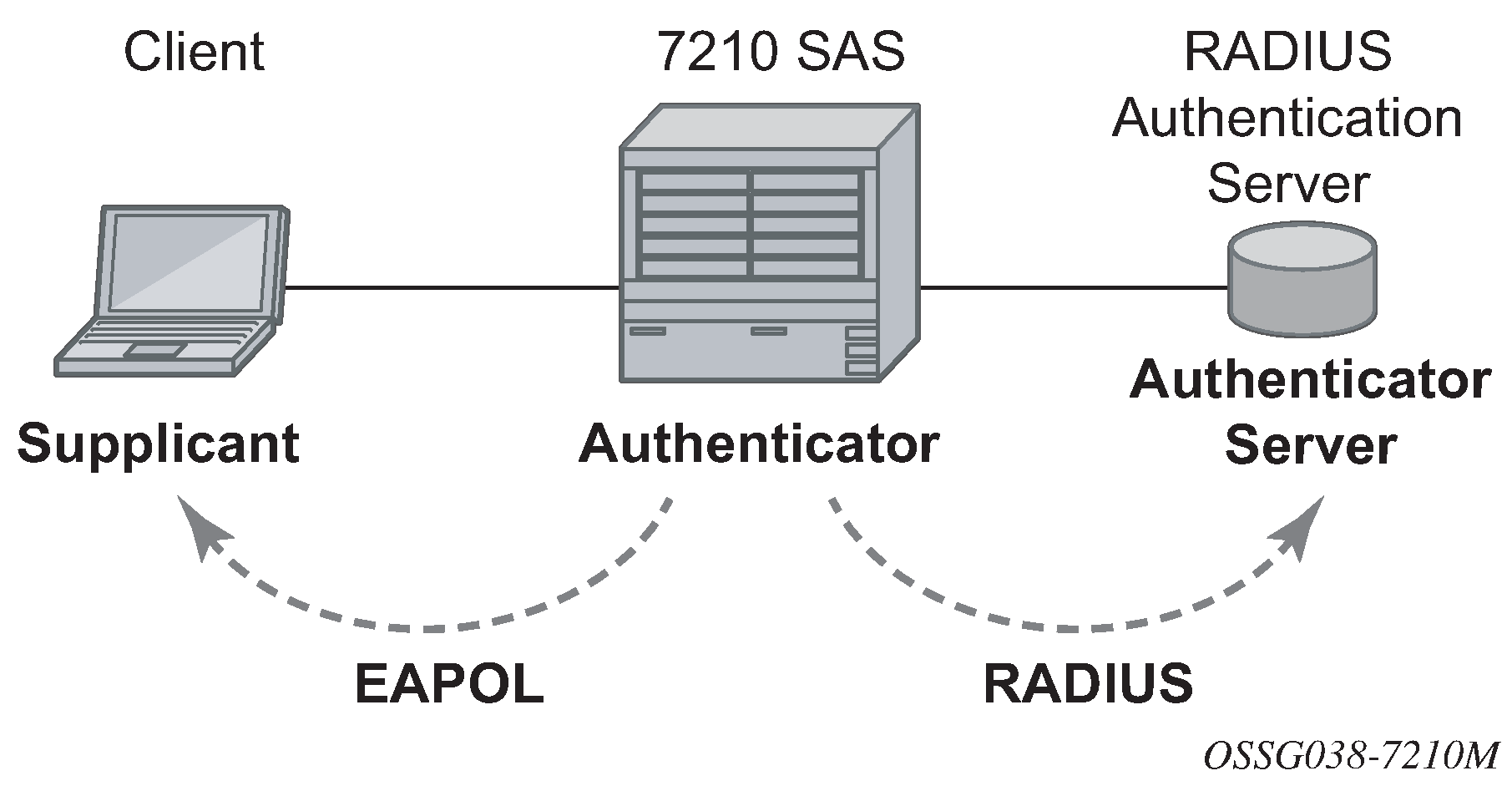
The following figure shows the messages involved in the authentication procedure.
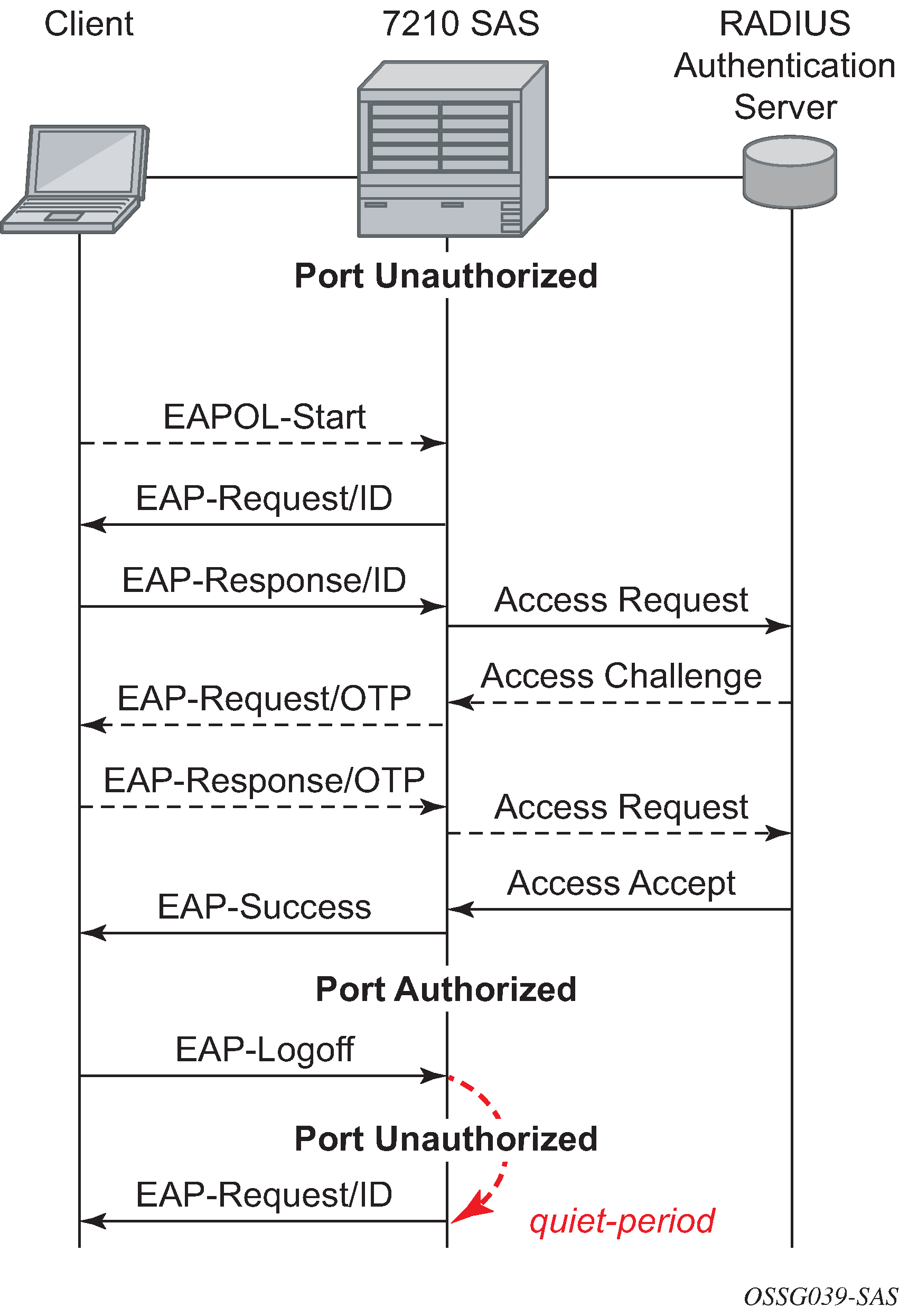
The router will initiate the procedure when the Ethernet port becomes operationally up, by sending a special PDU called EAP-Request/ID to the client. The client can also initiate the exchange by sending an EAPOL-start PDU, if it does not receive the EAP-Request/ID frame during bootup. The client responds on the EAP-Request/ID with a EAP-Response/ID frame, containing its identity (typically username + password).
After receiving the EAP-Response/ID frame, the router will encapsulate the identity information into a RADIUS AccessRequest packet, and send it off to the configured RADIUS server.
The RADIUS server checks the supplied credentials, and if approved will return an Access Accept message to the router. The router notifies the client with an EAP-Success PDU and puts the port in authorized state.
802.1x timers
The 802.1x authentication procedure is controlled by a number of configurable timers and scalars. There are two separate sets, one for the EAPOL message exchange and one for the RADIUS message exchange.
EAPOL timers:
transit-period
Indicates how many seconds the Authenticator will listen for an EAP-Response/ID frame. If the timer expires, a new EAP-Request/ID frame will be sent and the timer restarted. The default value is 60. The range is 1 to 3600 seconds.
supplicant-timeout
This timer is started at the beginning of a new authentication procedure (transmission of first EAP-Request/ID frame). If the timer expires before an EAP-Response/ID frame is received, the 802.1x authentication session is considered as having failed. The default value is 30. The range is 1 to 300.
quiet-period
Indicates number of seconds between authentication sessions It is started after logout, after sending an EAP-Failure message or after expiry of the supplicant-timeout timer. The default value is 60. The range is 1 to 3600.
RADIUS timer and scaler:
max-auth-req
Indicates the maximum number of times that the router will send an authentication request to the RADIUS server before the procedure is considered as having failed. The default value is value 2. The range is 1 to 10.
server-timeout
Indicates how many seconds the authenticator will wait for a RADIUS response message. If the timer expires, the access request message is sent again, up to max-auth-req times. The default value is 60. The range is 1 to 3600 seconds.
The following figure shows sample EAPOL and RADIUS timers on the 7210 SAS.
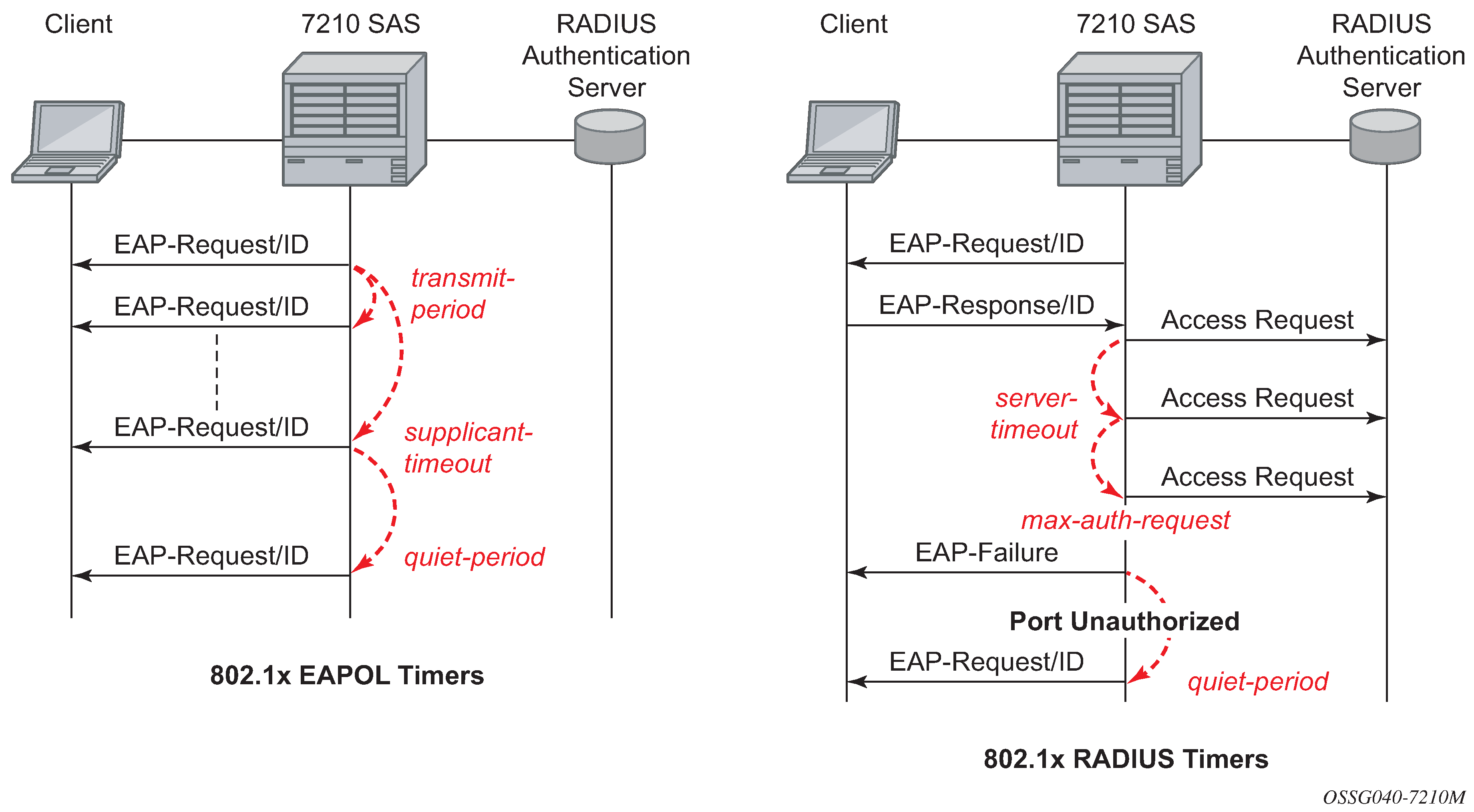
The router can also be configured to periodically trigger the authentication procedure automatically. This is controlled by the enable re-authentication and reauth-period parameters. Reauth-period indicates the period in seconds (since the last time that the authorization state was confirmed) before a new authentication procedure is started. The range of reauth-period is 1 to 9000 seconds (the default is 3600 seconds, one hour). Note that the port stays in an authorized state during the re-authentication procedure.
802.1x configuration and limitations
Configuration of 802.1x network access control on the router consists of two parts:
generic parameters, which are configured under config>security>dot1x
port-specific parameters, which are configured under config>port>ethernet>dot1x
801.x authentication:
Provides access to the port for any device, even if only a single client has been authenticated.
Can only be used to gain access to a predefined Service Access Point (SAP). It is not possible to dynamically select a service (such as a VPLS service) depending on the 802.1x authentication information.
802.1x tunneling for Epipe service
Customers who subscribe to Epipe service considers the Epipe as a wire, and run 802.1x between their devices which are located at each end of the Epipe.
This feature only applies to port-based Epipe SAPs because 802.1x runs at port level not VLAN level. Therefore such ports must be configured as null encapsulated SAPs.
When 802.1x tunneling is enabled, the 802.1x messages received at one end of an Epipe are forwarded through the Epipe. When 802.1x tunneling is disabled (by default), 802.1x messages are dropped or processed locally according to the 802.1x configuration (shutdown or no shutdown).
Enabling 802.1x tunneling requires the 802.1x mode to be set to force-auth. Enforcement is performed on the CLI level.
MAC authentication
MAC authentication is only supported on 7210 SAS-Mxp, 7210 SAS-R6, 7210 SAS-Sx/S 1/10GE, and 7210 SAS-T.
The 7210 SAS supports the 802.1x EAP standard for authenticating Ethernet devices before they can access the network. However, if a client device does not support 802.1x EAP, MAC authentication can be used to prevent unauthorized traffic from being transmitted through the 7210 SAS.
Because MAC authentication is a fallback mechanism, the user must first enable 802.1x EAP to use MAC authentication on the 7210 SAS. To authenticate a port using MAC authentication, first configure 802.1x authentication on the 7210 SAS by enabling port-control auto, and then configure mac-auth on the 7210 SAS to enable MAC authentication.
Layer 2 control protocols affect MAC authentication behavior differently depending on the protocol in use; see Layer 2 control protocol interaction with authentication methods for more information.
MAC authentication basics
When a port becomes operationally up with MAC authentication enabled, the 7210 SAS (as the authenticator) performs the following steps:
After transmission of the first EAP-Request/ID PDU, the 7210 SAS starts the mac-auth-wait timer and begins listening on the port for EAP-Response/ID PDUs. At this point, the 7210 SAS only listens to EAPOL frames. If EAPOL frames are received, 802.1x authentication is chosen.
Note:If it is known that the attached equipment does not support EAP, you can configure no mac-auth-wait so that MAC authentication is used as soon as the port is operationally up.
If the mac-auth-wait timer expires, and no EAPOL frames have been received, the 7210 SAS begins listening on the port for any Ethernet frames.
If the 7210 SAS receives an Ethernet frame, the 7210 SAS scans the client source MAC address in the frame and transmits the MAC address to the configured RADIUS server for comparison against the MAC addresses configured in its database.
The following attributes are contained in the RADIUS message:
User-Name
This attribute specifies the source MAC address of the client device.
User-Password
This attribute specifies the source MAC address of the client device in an encrypted format.
Service-Type
This attribute specifies the type of service that the client has requested; the value is set to 10 (call-check) for MAC authentication requests.
Calling-Station-Id
This attribute specifies the source MAC address of the client device.
NAS-IP-Address
This attribute specifies the IP address of the device acting as the authenticator.
NAS-Port
This attribute specifies the physical port of the device acting as the authenticator.
Message-Authenticator
This attribute is used to authenticate and protect the integrity of Access Request messages to prevent spoofing attacks.
If the MAC address is approved by the RADIUS server, the 7210 SAS enables the port for traffic transmission by that particular MAC address, which is successfully authenticated.
If the MAC address is rejected by the RADIUS server, the 7210 SAS will not authenticate the port using either 802.1x or MAC authentication. If an Ethernet frame with the same MAC address is received, the 7210 SAS returns to step3 and reattempts approval of the MAC address.
If a port that was previously authenticated with MAC authentication receives an EAPOL-Start frame, the port will not reauthenticate using 802.1x EAPOL.
While the port is unauthenticated, the port will be down to all upper layer protocols or services.
When a MAC address is authenticated, only packets whose source MAC address matches the authenticated MAC address are forwarded when the packets are received on the port, and only packets whose destination MAC address matches the authenticated MAC address are forwarded out of the port.
Broadcast and multicast packets at ingress are sent for source MAC address authentication. Broadcast and multicast packets at egress are forwarded as normal.
Unknown destination packets at ingress are copied to the CPU and MAC authentication is attempted. Unknown destination packets at egress are dropped.
MAC authentication limitations
MAC authentication is subject to the following limitations:
If MAC authentication is configured on ports that are part of a LAG, the authenticated MAC address is forwarded in the egress direction out of any port in the LAG.
If MAC authentication is configured on a port and the port is added to or removed from a LAG, all previously authenticated MACs are reauthenticated by the system.
Caution:A small amount of traffic loss may occur while MAC reauthentication is in progress.
VLAN authentication
VLAN authentication is only supported on 7210 SAS-Mxp, 7210 SAS-R6, 7210 SAS-Sx/S 1/10GE, and 7210 SAS-T.
The 7210 SAS supports VLAN authentication, which operates similarly to 802.1x network access control but only uses VLAN-tagged EAPOL frames to trigger the authentication process on a per-VLAN basis, or uses null-tagged EAPOL frames to authenticate and authorize processing of service traffic received in the context of a Dot1q explicit null SAP. See 802.1x network access control for information about 802.1x network access control and authentication.
To authenticate a port using VLAN authentication, you must first configure 802.1x authentication on the 7210 SAS by enabling port-control auto, and then configure vlan-auth on the 7210 SAS to enable VLAN authentication and allow VLAN authentication functionality to supersede that of basic 802.1x authentication.
VLAN authentication and MAC authentication are mutually exclusive. MAC authentication cannot be configured on a port while VLAN authentication is already configured on the same port. See MAC authentication for information about MAC authentication.
Layer 2 control protocols affect VLAN authentication behavior differently depending on the protocol in use; see Layer 2 control protocol interaction with authentication methods for more information.
VLAN authentication basics
When a port becomes operationally up with VLAN authentication enabled, the 7210 SAS (as the authenticator) performs the following steps:
After transmission of the first EAP-Request/ID PDU, the 7210 SAS begins listening on the port for VLAN-tagged EAPOL Start, Request-Identity frames from the access device connected to the port. Null-tagged EAPOL frames also trigger the authentication process if a Dot1q explicit null SAP is configured.
If the 7210 SAS receives a VLAN-tagged EAPOL frame (or a null-tagged EAPOL frame if a Dot1q explicit null SAP is configured), the 7210 SAS transmits the frame to the configured RADIUS server for comparison of the VLAN against the usernames configured in its database.
The User-Name attribute is contained in the RADIUS message. This attribute specifies the username received in the EAPOL frame from the client device.
If the VLAN is approved by the RADIUS server, the 7210 SAS maps all traffic received from the VLAN to a SAP and processes it in the context of the configured service.
If the VLAN is rejected by the RADIUS server, all traffic from the VLAN is dropped. The 7210 SAS enters a quiet period, configured using the quiet-period command, and will not authenticate the port using VLAN authentication. After the quiet period expires, the 7210 SAS returns to step1.
While the port is unauthenticated, the port will be down to all upper layer protocols or services.
VLAN authentication limitations
VLAN authentication is subject to the following limitations:
VLAN authentication is only supported on Dot1q-encapsulated ports. It is not supported on NULL or QinQ-encapsulated ports.
VLAN authentication only uses the outermost VLAN tag received in the packets. Packets with more than one tag are processed only if the outermost tag matches the SAP tag.
Restrictions on processing of SAP tags also apply to VLAN authenticated frames. VLAN authentication does not change the current behavior for frames mapped to different SAPs and services.
VLAN range SAPs are not supported on a port with VLAN authentication enabled.
Dot1q default SAPs configured on a port with Dot1q encapsulation do not support VLAN authentication.
Dot1q explicit null SAPs can be configured on a port with Dot1q encapsulation, which requires authentication of null-tagged EAPOL frames.
Layer 2 control protocol interaction with authentication methods
The following table describes the interactions of Layer 2 control protocols with 802.1x authentication, MAC authentication, and VLAN authentication.
Layer 2 control protocol |
802.1x port authentication enabled |
MAC authentication enabled |
VLAN authentication enabled |
|
|---|---|---|---|---|
Dot1q explicit null SAP not configured |
Dot1q explicit null SAP configured |
|||
EFM OAM |
Allow |
Allow |
Allow |
Allow |
LLDP |
Block if port is unauthenticated Allow if port is authenticated |
Block if MAC is unauthenticated Allow if MAC is authenticated |
Allow |
Allow |
LACP |
Block if port is unauthenticated Allow if port is authenticated |
Block if MAC is unauthenticated Allow if MAC is authenticated |
LAG and LACP are not supported on ports with VLAN authentication enabled |
LAG and LACP are not supported on ports with VLAN authentication enabled |
CFM |
Block if port is unauthenticated Allow if port is authenticated |
Block if MAC is unauthenticated Allow if MAC is authenticated |
Block if VLAN (SAP) is unauthenticated Allow only if specific VLAN is authenticated |
Block if null SAP is unauthenticated Allow if null SAP is authenticated |
xSTP (STP/RSTP/MSTP) |
Block if port is unauthenticated Allow if port is authenticated |
Block if MAC is unauthenticated Allow if MAC is authenticated |
Block if VLAN (SAP) is unauthenticated Allow if VLAN (SAP) is authenticated |
Block if null SAP is unauthenticated Allow if null SAP is authenticated |
802.3ah OAM
802.3ah Clause 57 (EFM OAM) defines the Operations, Administration, and Maintenance (OAM) sublayer, which provides mechanisms useful for monitoring link operation such as remote fault indication and remote loopback control. In general, OAM provides network operators the ability to monitor the health of the network and quickly determine the location of failing links or fault conditions. EFM OAM described in this clause provides data link layer mechanisms that complement applications that may reside in higher layers.
OAM information is conveyed in slow protocol frames called OAM protocol data units (OAMPDUs). OAMPDUs contain the appropriate control and status information used to monitor, test, and troubleshoot OAM-enabled links. OAMPDUs traverse a single link being passed between peer OAM entities, and therefore, are not forwarded by MAC clients (like bridges or switches).
The following EFM OAM functions are supported:
EFM OAM capability discovery
active and passive modes
remote failure indication mechanism to handle critical link events, including link fault and dying gasp
dying gasp support; EFM OAM dying gasp messages and SNMP dying gasp messages are mutually exclusive and are generated on power failure. See the 7210 SAS-Mxp, R6, R12, S, Sx, T System Management Guide for more information about support for SNMP dying gasp.
All 7210 SAS platforms process the EFM OAM dying gasp message received on a port enabled for EFM and generate an SNMP trap. Support for generation of dying gasp messages on 7210 SAS platforms is listed in the following table.
Table 16. Dying gasp message support on 7210 SAS platforms 7210 SAS platform
Dying gasp message support 46
7210 SAS-Mxp
✓
7210 SAS-R6
7210 SAS-R12
7210 SAS-Sx/S 1/10GE
✓
7210 SAS-Sx 10/100GE
✓
7210 SAS-T
✓
loopback, a mechanism provided to support a data link layer frame-level loopback mode. Both remote and local loopback modes are supported.
EFM OAMPDU tunneling
high resolution timer for EFM OAM in 500ms interval (minimum)
OAM events
-
link fault
The PHY has determined a fault has occurred in the receive direction of the local DTE.
-
dying gasp
An unrecoverable local failure condition has occurred.
-
critical event
An unspecified critical event has occurred.
These critical link events are signaled to the remote DTE by the flag field in OAM PDUs.
The 7210 SAS does not generate EFM OAM PDUs with these flags except for the dying gasp flag. However, it supports processing of these flags in EFM OAM PDUs received from the peer.
Remote loopback
EFM OAM provides a link-layer frame loopback mode that can be remotely controlled.
To initiate remote loopback, the local EFM OAM client sends a loopback control OAM PDU by enabling the OAM remote-loopback command. After receiving the loopback control OAM PDU, the remote OAM client puts the remote port into local loopback mode.
To exit remote loopback, the local EFM OAM client sends a loopback control OAM PDU by disabling the OAM remote-loopback command. After receiving the loopback control OAM PDU, the remote OAM client puts the port back into normal forwarding mode.
Note that during remote loopback test operation, all frames except EFM OAM PDUs are dropped at the local port for the receive direction, where remote loopback is enabled. If local loopback is enabled, then all frames except EFM OAM PDUs are dropped at the local port for both the receive and transmit directions. This behavior may result in many protocols (such as STP or LAG) resetting their state machines.
802.3ah OAM PDU tunneling for Epipe service
The 7210 SAS routers support 802.3ah. Customers who subscribe to Epipe service treat the Epipe as a wire, so they demand the ability to run 802.3ah between their devices which are located at each end of the Epipe.
This feature only applies to port-based Epipe SAPs because 802.3ah runs at the port level, not at the VLAN level. Therefore, such ports must be configured as null encapsulated SAPs.
When OAM PDU tunneling is enabled, 802.3ah OAM PDUs received at one end of an Epipe are forwarded through the Epipe. 802.3ah can run between devices that are located at each end of the Epipe. When OAM PDU tunneling is disabled (by default), OAM PDUs are dropped or processed locally according to the efm-oam configuration (shutdown or no shutdown).
Note that by enabling 802.3ah for a specific port and enabling OAM PDU tunneling for the same port are mutually exclusive.
MTU configuration guidelines
The 7210 SAS devices provide the option to configure MTU limitations at many service points. The physical (access and network) port, service, and SDP MTU values must be individually defined.
MTU values must conform to both of the following conditions:
The service MTU must be less than or equal to the SDP path MTU.
The service MTU must be less than or equal to the access port (SAP) MTU.
Default MTU values
The following table describes the default MTU values that are dependent upon the (sub-) port type, mode, and encapsulation.
Port type |
Mode |
Encap type |
Default (bytes) |
|---|---|---|---|
Ethernet |
access |
null |
1514 |
Ethernet |
access |
dot1q |
1518 |
Port mode |
access |
qinq |
1522 |
Fast Ethernet |
network |
— |
1514 |
Other Ethernet |
network |
— |
9212 |
Ethernet |
hybrid |
— |
9212 |
Notes:
The no service-mtu-check command disables service MTU check. Disabling the service MTU check allows packets to pass to the egress if the packet length is less than or equal to the MTU configured on the port. The length of the packet sent from a SAP is limited only by the access port MTU. In case of a pseudowire, the length of the packet is limited by the network port MTU (including the MPLS encapsulation).
In 7210 SAS, length of the SAP tag (or service-delimiting tag, for a packet received over a pseudowire) is included in the computation of the packet length before comparing it with the service-MTU configured for the service. Packet length= Length of IP packet + L2 header + length of SAP tag
For example, if the IP packet received over a dot1q SAP is 1500 and the service-MTU configured is 1514, the service MTU validation check fails as:
Packet length=1500 (Length of IP packet) +14 (L2 header) +4 (length of SAP tag) =1518. The packet is dropped as packet length is greater than the service MTU configured.
See the 7210 SAS release notes for other restrictions with regards to MTU checking and processing on each of the platforms.
Deploying preprovisioned components on 7210 SAS
This section describes the deployment of preprovisioned components on 7210 SAS platforms.
Deploying preprovisioned components for 7210 SAS-T, 7210 SAS-Mxp, 7210 SAS-Sx/S 1/10GE, and 7210 SAS-Sx 10/100GE.
Appropriate MDAs are auto-provisioned on the 7210 SAS-T, 7210 SAS-Mxp, 7210 SAS-Sx/S 1/10GE, and 7210 SAS-Sx 10/100GE. The user is not required to provision the slots or MDA on these platforms.
Deploying preprovisioned components for 7210 SAS-R6 and 7210 SAS-R12
When a line card or MDA is installed in a preprovisioned slot, the device detects discrepancies between the preprovisioned card and MDA type configurations and the types actually installed. Error messages display if there are inconsistencies and the card does not initialize.
When the correct preprovisioned cards are installed in the appropriate chassis slot, alarm, status, and performance details display.
The 7210 SAS-R6 has 6 IMM slots and 2 SF/CPM slots, which are not auto-provisioned and need to be provisioned by the user.
The 7210 SAS-R12 has 12 IMM slots and 2 SF/CPM slots, which are not auto-provisioned and need to be provisioned by the user.
The 7210 SAS-R6 and 7210 SAS-R12 allow the user to preprovision the chassis to accept either IMMv2 or IMM-c cards. By default, without any configuration, the chassis accepts IMMv2 cards. Use the configure>system>allow-imm-family command to configure the type of card the chassis can accept and reboot the device for the value to take effect. See the 7210 SAS-Mxp, R6, R12, S, Sx, T Basic System Configuration Guide for more information about this command.
Configuration process overview
The following figure shows the process to provision chassis slots (if any), line cards (if any), MDAs (if any), and ports.
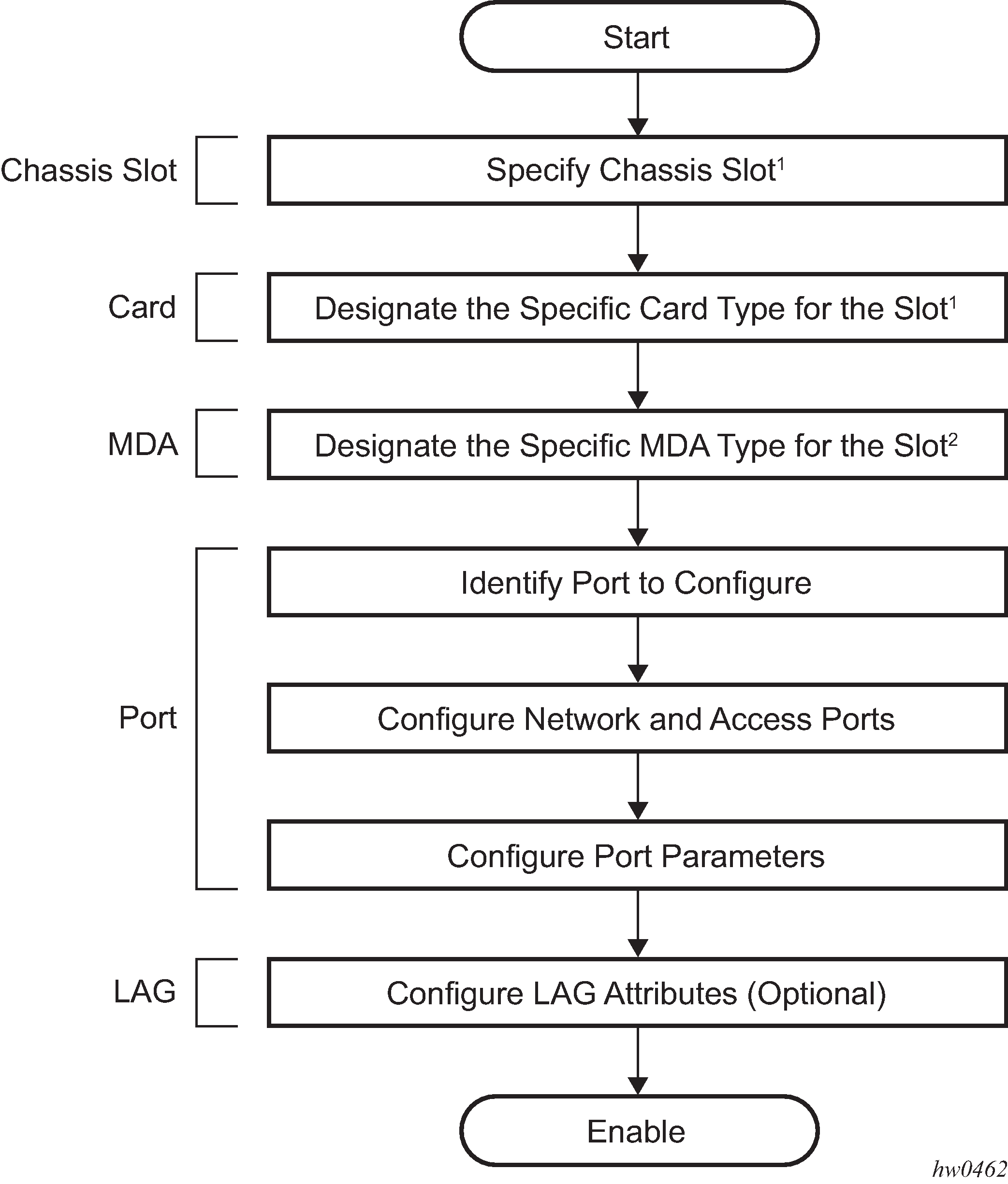
Specifying the chassis slot and card type is not needed for fixed platforms such as 7210 SAS-T, 7210 SAS-Mxp, 7210 SAS-Sx/S 1/10GE and 7210 SAS-Sx 10/100GE; these platforms do not support removable cards. On fixed platforms, the card type is auto-provisioned. It is typically used only on chassis-based platforms that support slots for inserting cards, such as the 7210 SAS-R6 and 7210 SAS-R12.
Specifying the MDA type is not required on platforms that do not support an MDA, such as 7210 SAS-T, 7210 SAS-Sx/S 1/10GE, 7210 SAS-Sx 10/100GE, 7210 SAS-R6, and 7210 SAS-R12. 7210 SAS-Mxp does not have a expansion slot and therefore does not support MDAs.
Configuring physical ports with CLI
This section provides information to configure ports.
Preprovisioning guidelines
The 7210 SAS platforms have a console port to connect terminals to the device. The Ethernet management port is supported.
Configure parameters from a system console connected to a console port, using Telnet to access the device remotely or SSH to open a secure shell connection.
Predefining entities
On 7210 SAS platforms, where cards/MDAs are not auto-provisioned, to initialize a card, the chassis slot, line card type, and MDA type must match the preprovisioned parameters. In this context, preprovisioning means to configure the entity type (such as the line card type, MDA type, port, and interface) that is planned for a chassis slot, line card, or MDA. Preprovisioned entities can be installed but not enabled or the slots can be configured but remain empty until populated. Provisioning means that the preprovisioned entity is installed and enabled.
You can:
provision the chassis to accept specific IMM cards on the 7210 SAS-R6 and 7210 SAS-R12
preprovision ports and interfaces after the line card and MDA types are specified.
install line cards in slots with no preconfiguration parameters specified. When the card is installed, the card and MDA types must be specified. This is required on 7210 SAS chassis-based platforms (7210 SAS-R6 and 7210 SAS-R12). On 7210 SAS platforms that do not support any removable cards or MDAs, the cards are preprovisioned for fixed ports.
install a line card in a slot provisioned for a different card type (the card will not initialize). The existing card and MDA configuration must be deleted and replaced with the current information. This is required on 7210 SAS chassis-based platforms (7210 SAS-R6 and 7210 SAS-R12). On 7210 SAS platforms that do not support any removable cards or MDAs, the MDAs are preprovisioned for all fixed ports.
Preprovisioning a port
On 7210 SAS chassis-based platforms (7210 SAS-R6 and 7210 SAS-R12), before a port can be configured, the slot must be preprovisioned with an allowed card type or the MDA must be preprovisioned with an allowed MDA type.
Some recommendations to configure a port include:
Ethernet
Configure an access port for customer facing traffic on which services are configured.
An encapsulation type may be specified to distinguish services on the port or channel. Encapsulation types are not required for network ports.
To configure an Ethernet access port, see Ethernet access port.
Configure a network port to participate in the service provider transport or infrastructure network.
To configure an Ethernet network port, see Ethernet network port.
Accounting policies can only be associated with network ports and Service Access Points (SAPs). Accounting policies are configured in the config>log>accounting-policy context.
When ports are preprovisioned, Link Aggregation Groups (LAGs) can be configured to increase the bandwidth available between two nodes. All physical links in a specific LAG combine to form one logical connection. A LAG also provides redundancy in case one or more links that participate in the LAG fail. For command syntax, see Configuring LAG parameters.
Basic configuration
For 7210 SAS platforms that do not support any removable cards or MDAs (7210 SAS-T, 7210 SAS-Mxp, 7210 SAS-Sx/S 1/10GE, and 7210 SAS-Sx 10/100GE), the card and MDA is auto-provisioned and operators can directly start with identifying and configuring the ports as follows.
On 7210 SAS chassis-based platforms, (7210 SAS-R6 and 7210 SAS-R12), the card type must be provisioned and operators need to start from identifying the chassis slot and configuration of the slot and card type, as shown below.
The most basic configuration must have the following:
identify chassis slot (if applicable)
specify line card type (must be an allowed card type).
identify MDA slot (if applicable)
specify MDA (must be an allowed MDA type) – if applicable
identify specific port to configure
Configuring cards and MDAs
Card configurations include a chassis slot designation.
The following is a sample of card configuration output for the 7210 SAS-R6.
A:SASR6>config>card# info
----------------------------------------------
        card-type imm-sas-2xfp
        mda 1
            no shutdown
        exit
        no shutdown
----------------------------------------------
A:SASR6>config>card#
Configuration notes for provisioning of cards
The following provisioning guidelines and restrictions apply:
On 7210 SAS systems that require provisioning of the card type (7210 SAS-R6 and 7210 SAS-R12), if a card type is installed in a slot provisioned for a different type, the card will not initialize.
On 7210 SAS systems that require provisioning of a card (7210 SAS-R6 and 7210 SAS-R12), if the card is installed in an unprovisioned slot, it will remain administratively and operationally down until the card type is specified.
Ports cannot be provisioned until the slot and card type are specified, on systems that require provisioning of the card. Ports can be provisioned on bootup on systems that auto-provision the cards (7210 SAS-T, 7210 SAS-Sx/S 1/10GE, and 7210 SAS-Sx 10/100GE).
Configuration notes for provisioning of 7210 SAS-R6 IMMv2 (IMM-b) cards
The 7210 SAS-R6 platform supports IMM version-2 cards (imm-sas-b variants). To use IMMv2 cards, you must provision the chassis using the config>system>chassis>allow-imm-family CLI command as shown below. This command allows the software know which version of cards will be used in the system and allows it to initialize the system appropriately with the correct set of parameters. A change to this value requires a reboot of the chassis.
 config>system>chassis#
         allow-imm-family imm-family
where:
imm-family = imm-sas-r-b | imm-sas-r-c
imm-sas-r-b: use for IMMv2
imm-sas-r-c: use for IMM-c
For the list of IMMs supported in a particular release, see the release notes.
The user can change the value of allow-imm-family at any time. It does not change the operational state of the chassis. For the value to take effect, the user must reboot. If the software detects a mismatch in the cards specified by allow-imm-family and the IMM cards provisioned/equipped in the chassis, it will generate an error as shown below.
*A:NS140500018# /configure system chassis allow-imm-family ?
  - allow-imm-family <imm-family>
  - no allow-imm-family

<imm-family>         : imm-sas-r-b|imm-sas-r-c
*A:NS140500018# /configure system chassis allow-imm-family imm-sas-r-b
INFO: CHMGR #4004 Configuration changes successful. Reboot the chassis for configura
tion to take effect.
Use the following command to display a list of supported cards per family.
*A:sasr_dutb>show>system# chassis imm-family all

===============================================================================
IMM FAMILY INFORMATION
===============================================================================
IMM-TYPE                      IMM-FAMILY          SUPPORTED
-------------------------------------------------------------------------------
imm-sas-b-4sfp+               imm-sas-r-b         ----
imm-sas-b-2sfp+               imm-sas-r-b         ----
imm-sas-b-10sfp-1sfp+         imm-sas-r-b         ----
imm-sas-b-11csfp              imm-sas-r-b         ----
imm-sas-b-16tx                imm-sas-r-b         ----
===============================================================================
*A:sasr_dutb>show>system#
Use the following command to display the list of IMM cards allowed in the chassis based on the configured value of allow-imm-family .
*A:sasr_dutb>show>system# chassis imm-family configured

===============================================================================
IMM FAMILY INFORMATION
===============================================================================
IMM-TYPE                      IMM-FAMILY          SUPPORTED
-------------------------------------------------------------------------------
imm-sas-b-4sfp+               imm-sas-r-b         ----
imm-sas-b-2sfp+               imm-sas-r-b         ----
imm-sas-b-10sfp-1sfp+         imm-sas-r-b         ----
===============================================================================
*A:sasr_dutb>show>system#
For more information about upgrading the chassis to use IMMv2 cards, see the 7210 SAS-R6 Chassis Installation Guide.
Configuration notes for provisioning of 7210 SAS-R6 IMM-c cards
The user has the option to aggregate 1G and 10G customer services to 100GE uplinks to meet the increasing bandwidth needs in access networks by provisioning 7210 SAS-R6 IMM-c cards. Both the QSFP28 (named imm-sas-c-1qsfp28) and CFP4 (named imm-sas-c-1cfp4) variants are supported, providing the flexibility of using optics based on needs.
Before using the card, the command config>system>chassis>allow-imm-family imm-sas-r-c must be used, followed by a reboot of the node to allow the system to initialize correctly when using the new card.
On both the 7210 SAS-R6 and 7210 SAS-R12, imm-b and imm-c can be used simultaneously (that is, some slots can be populated with imm-b and some slots can be populated with imm-c). To achieve that, configure both imm-sas-r-b and imm-sas-r-c using the CLI command config>system>chassis>allow-imm-family. The system scaling of the functions supported when a mix of IMM-b and IMM-c are in use in the chassis is the lower of the scaling supported by each of the cards. See the scaling guide or contact your Nokia representative for more information.
 config>system>chassis#
         allow-imm-family imm-family
where:
imm-family = imm-sas-r-b | imm-sas-r-c
imm-sas-r-b: use for IMMv2
imm-sas-r-c: use for IMM-c
The following guidelines and restrictions apply:
IMM-c supports hot-swapping (after one-time configuration of the node).
On the 7210 SAS-R6, only two 100GE IMM-c cards in specified slots can be used. On the 7210 SAS-R12, all slots can be populated with 100GE IMM-c cards.
SyncE (as a reference and for distribution of frequency) and PTP (IEEE default and G.8265.1 profile) are available for use with the 100GE port.
Supports eight egress queues per network port for egress queuing and scheduling, along with MPLS EXP based marking, for prioritizing service traffic on network uplinks. Supports network port ingress classification with policing and network IP interface ingress classification with policing to differentiate and prioritize service traffic.
100GE QSFP28 IMM-c variant does not provide a breakout option.
Common configuration tasks
This section describes common configuration tasks.
Configuring ports
*A:7210SAS_duth>config>port# info detail
----------------------------------------------
        description "10/100/Gig Ethernet TX"
        access
            egress
                pool default
                    resv-cbs default
                    slope-policy "default"
                exit
            exit
        exit
        network
            egress
                pool default
                    no amber-alarm-threshold
                    no red-alarm-threshold
                    resv-cbs default
                    slope-policy "default"
                exit
            exit
        exit
----------------------------------------------
*A:7210_SAS_duth>config>port#
Configuring Ethernet port parameters
This section describes Ethernet port configuration.
Ethernet network port
A network port is network-facing and participates in the service provider transport or infrastructure network processes.
The following is a sample network port configuration output.
A:ALA-B>config>port# info
----------------------------------------------
   description "Ethernet network port"
   ethernet
      mode network
   exit
   no shutdown
----------------------------------------------
A:ALA-B>config>port#
Ethernet access-uplink port
Access-uplink ports are network-facing and transport customer services. Only QinQ encapsulation can be used.
The following is a sample access-uplink port configuration output.
A:ALA-B>config>port# info
----------------------------------------------
   description "Ethernet network port"
   ethernet
      mode access uplink
   exit
   no shutdown
----------------------------------------------
A:ALA-B>config>port#
Ethernet access port
Services are configured on access ports used for customer-facing traffic. If a SAP is to be configured on a port, it must be configured in access mode. When a port is configured for access mode, the appropriate encapsulation type can be specified to distinguish the services on the port. When a port has been configured for access mode, multiple services may be configured on the port.
The following is a sample Ethernet access port configuration output.
*A:7210-SAS>config>port# info
----------------------------------------------
        ethernet
            mode access
            access
                egress
                exit
                ingress
                exit
            exit
            encap-type dot1q
            mtu 9212
        exit
        no shutdown
----------------------------------------------
*A:7210-SAS>
Configuring 802.1x authentication port parameters
The following is a sample 802.1x port configuration output.
A:ALA-A>config>port>ethernet>dot1x# info detail
----------------------------------------------
                port-control auto
                radius-plcy dot1xpolicy
                re-authentication
                re-auth-period 3600
                max-auth-req 2
                transmit-period 30
                quiet-period 60
                supplicant-timeout 30
                server-timeout 30
----------------------------------------------
Configuring MAC authentication port parameters
MAC authentication is only supported on 7210 SAS-Mxp, 7210 SAS-R6, 7210 SAS-Sx/S 1/10GE, and 7210 SAS-T.
The 7210 SAS supports a fallback MAC authentication mechanism for client devices (for example, PCs and cameras) on an Ethernet network that do not support 802.1x EAP.
MAC authentication provides protection against unauthorized access by forcing the device connected to the 7210 SAS to have its MAC address authenticated by a RADIUS server before the device is able to transmit packets through the 7210 SAS.
Use the following CLI syntax to configure MAC authentication for an Ethernet port.
 port port-id ethernet
         dot1x
             mac-auth
             mac-auth-wait seconds
             port-control auto
             quiet-period seconds
             radius-plcy name
The following example shows the command usage to configure MAC authentication for an Ethernet port.
     config# port 1/1/2 ethernet dot1x
     config>port>ethernet>dot1x# mac-auth
     config>port>ethernet>dot1x# mac-auth-wait 20
     config>port>ethernet>dot1x# port-control auto
     config>port>ethernet>dot1x# quiet-period 60
     config>port>ethernet>dot1x# radius-plcy dot1xpolicy
Port configuration output
Use the info detail command to display port configuration information.
SAS-T>config>port>ethernet>dot1x# info detail
----------------------------------------------
             port-control auto
             radius-plcy dot1xpolicy
             re-authentication
             re-auth-period 3600
             max-auth-req 2
             transmit-period 30
             quiet-period 60
             supplicant-timeout 30
             server-timeout 30
             mac-auth
             mac-auth-wait 20
----------------------------------------------
SAS-T>config>port>ethernet>dot1x#
Configuring VLAN authentication port parameters
VLAN authentication is only supported on 7210 SAS-Mxp, 7210 SAS-R6, 7210 SAS-Sx/S 1/10GE, and 7210 SAS-T.
The 7210 SAS supports VLAN authentication for client devices (for example, PCs and STBs) on an Ethernet network.
VLAN authentication provides protection against unauthorized access by forcing the device connected to the 7210 SAS to be authenticated by a RADIUS server before the device is able to transmit packets through the 7210 SAS.
Use the following CLI syntax to configure VLAN authentication for an Ethernet port.
 port port-id ethernet
         dot1x
             vlan-auth
             port-control auto
             quiet-period seconds
             radius-plcy name
The following example shows the command usage to configure VLAN authentication for an Ethernet port.
     config# port 1/1/2 ethernet dot1x
     config>port>ethernet>dot1x# vlan-auth
     config>port>ethernet>dot1x# port-control auto
     config>port>ethernet>dot1x# quiet-period 60
     config>port>ethernet>dot1x# radius-plcy dot1xpolicy
Port configuration output
Use the info detail command to display port configuration information.
SAS-T>config>port>ethernet>dot1x# info detail
----------------------------------------------
             port-control auto
             radius-plcy dot1xpolicy
             re-authentication
             re-auth-period 3600
             max-auth-req 2
             transmit-period 30
             quiet-period 60
             supplicant-timeout 30
             server-timeout 30
             vlan-auth
----------------------------------------------
SAS-T>config>port>ethernet>dot1x#
Configuring LAG parameters
The following guidelines and restrictions apply for LAG configurations:
LAG configurations must include at least two ports.
Up to eight ports can be included in a LAG, depending on the platform. All ports in the LAG must share the same characteristics (speed, duplex, hold-timer, and so on). The port characteristics are inherited from the primary port.
Autonegotiation must be disabled or set to limited mode for ports that are part of a LAG to guarantee a specific port speed.
Ports in a LAG must be configured as full duplex.
The 7210 SAS-Mxp, 7210 SAS-R6, and 7210 SAS-R12 support IP DSCP table-based classification for LAG. See ‟Service Ingress QoS Policies” in the 7210 SAS-Mxp, R6, R12, S, Sx, T Quality of Service Guide for more information.
LAG configuration output
*A:7210SAS>config>lag# info detail
----------------------------------------------
        no mac
        mode hybrid
        encap-type dot1q
        no enable-dei
        no enable-table-classification
        port 6/1/1 priority 32768 sub-group 1
        no dynamic-cost
        lacp active administrative-key 32770
        port-threshold 0 action down
        lacp-xmit-interval fast
        lacp-xmit-stdby
        no selection-criteria
        no hold-time
        standby-signaling lacp
        no shutdown
----------------------------------------------
*A:7210SAS>config>lag#
Configuring BFD Over LAG links
After the LAG and associated links are configured, you can configure BFD in the LAG context to create and establish the micro-BFD session per link. Before micro-BFD can be established, an IP interface must be associated with the LAG or a VLAN within the LAG, if dot1q encapsulation is used.
Perform the following to enable and configure BFD over individual LAG links.
Within the lag context, enter the bfd context and enable BFD.
Configure the address family for the micro-BFD sessions. Only one address family per LAG can be configured. On the 7210 SAS-T, 7210 SAS-R6, and 7210 SAS-R12, only the IPv4 address family can be configured.
Configure the local IP address for the BFD sessions.
Configure the remote IP address for the BFD sessions.
When configuring the local and remote IP address for the BFD over LAG link sessions, ensure that the local-ip parameter should always match an IP address associated with the IP interface to which the LAG is bound. In addition, the remote-ip parameter must match an IP address on the remote system and should also be in the same subnet as the local-ip address. If the LAG bundle is reassociated with a different IP interface, modify the local-ip and remote-ip parameters to match the new IP subnet. The local-ip and remote-ip values do not have to match a configured interface in the case of tagged LAG or ports.
The following optional parameters can be configured for BFD over LAG links:
transmit interval
receive interval
multiplier
max-wait-for-up-time — This parameter controls how long a link will remain active if BFD is enabled after the LAG and associated links are active and in a forwarding state.
max-time-admin-down — This parameter controls how long the system will wait before bringing the associated link out of service if an admin down message is received from the far end.
The following is a sample configuration output.
*A:Dut-C>config>lag# info
----------------------------------------------
        bfd
            family ipv4
                local-ip-address 10.120.1.2
                receive-interval 1000
                remote-ip-address 10.120.1.1
                transmit-interval 1000
                no shutdown
            exit
        exit
        no shutdown
Configuring access egress queue overrides
Queue override support on an access port in the egress direction allows users to override queue parameters such as adaptation rule, percent CIR and PIR rates, queue management policy, queue mode, CIR and PIR rates, and queue weight.
When the queue override feature is not used, queue parameters for the port are taken from the access egress QoS policy assigned to the port.
The following is a sample queue override configuration output.
*A:dut-g>config>port>ethernet>access>egr>queue-override# info
----------------------------------------------
     queue "1" create
        queue-mgmt default
        queue-mode strict
        weight 7
        rate cir 3000 pir 90000
        adaptation-rule cir min pir max
        exit
     queue "5" create
        queue-mgmt 200
        queue-mode weighted
        weight 1
        percent-rate cir 5.00 pir 10.00
        adaptation-rule cir min pir closest
        exit
     queue "8" create
     exit
----------------------------------------------
*A:dut-g>config>port>ethernet>access>egr>queue-override#
CRC error monitoring
This feature allows the user to track CRC (cyclic redundancy check) errors received on a specific port. The detection mechanism is based around a configurable threshold specified by the administrator. Two thresholds are configurable, one for CRC degrade and one for CRC signal fail. The first threshold crossing generates an alarm, log entry, and trap, but does not bring the physical port down, while the second (signal fail) threshold crossing logs an alarm, generates a trap, and brings the port operationally down.
The thresholds are configurable with the CLI command config>port>ethernet crc-monitor.
This behavior is enabled on a per-port basis. By default, the command and functionality is disabled for signal degrade and signal fail.
The user can configure different values for the sf-threshold and the sd-threshold. However, the sf-threshold value must be less than or equal to the sd-threshold value.
The values provided by the user for threshold and multiplier are used to compute the error ratio as (multiplier * (10 ^ - (threshold value)). Port statistics are collected once per second and accumulated over the configured window size. Each second, the oldest sample is discarded and the new sample is added to a running total. If the error ratio exceeds the configured threshold (as computed previously) over the window size for 2 consecutive seconds, appropriate actions are taken as follows.
If the number of CRC errors exceeds the signal degrade threshold value, a log warning message, syslog event and SNMP trap with the message ‟CRC errors in excess of the configured degrade threshold <M>*10e-<N> Set” is raised.
If the CRC error rate increases further and exceeds the configured signal fail threshold value, an alarm log message, syslog event, and SNMP trap are raised, and the port is brought operationally down.
When the condition is cleared, a SNMP trap message to clear the event is generated.
Service management tasks
This section describes the service management tasks.
Modifying or deleting an MDA
To change an MDA type already provisioned for a specific slot/card, the slot/MDA/port configuration must be shut down and then the MDA must be deleted from the configuration. Modify and delete operations can be performed only on the MDAs that are not auto-equipped or auto-provisioned.
Use the following syntax to modify an MDA.
     config> port port-id
     shutdown
     config> card slot-number
     shutdown
     [no] mda mda-number
     [no] mda-type mda-type
     shutdown
Modifying a card type
The modify operation cannot be performed on an IOM card that is auto-equipped and auto-provisioned during bootup and is fixed.
     config> port port-id
     [no] shutdown
     config> card slot-number
     mda mda-number
     [no] mda-type mda-type
     [no] shutdown
Deleting a card
The delete operation cannot be performed on an IOM card that is auto-equipped and auto-provisioned during bootup and is fixed.
     config> port port-id
     shutdown
     config> card slot-number
     card-type card-type
     mda mda-number
     no mda-type mda-type
     no shutdown
Deleting port parameters
Use the following syntax to delete a port provisioned for a specific card.
     config>port port-id
     shutdown
     no port port-id
Card, MDA, and port command reference
Command hierarchies
Configuration commands
Hardware commands
config
    - [no] card slot-number
        - card-type card-type
        - sys-res-profile policy-id
        - no sys-res-profile
MDA commands
Port configuration commands for PTP port-based timestamp
config
    - port
    - no port
        - [no] ptp-hw-timestamp
Port-based split horizon group configuration commands
config
    - port
    - no port
        - split-horizon-group group-name
        - no split-horizon-group
config
    - [no] lag [lag-id]
        - [no] split-horizon-group group-name
Port configuration commands for DWDM Optics
config
    - port {port-id}
    - no port
        - description long-description-string
        - no description
        - dwdm
            - channel channel
Port loopback commands
configure
    - system
        - loopback-no-svc-port [mac-swap mac-swap port-id] [mirror mirror-port-id] [testhead testhead port-id] [p2mpbud p2mpbud-port-id [p2mp-bud-classification]]
        - no loopback-no-svc-port [mac-swap mac-swap port-id] [mirror mirror-port-id] [testhead testhead port-id] [p2mpbud p2mpbud-port-id]
Port QoS slope policy commands
config
    - port
    - no port
        - access
            - egress
                - [no] pool [name]
                    -  slope-policy name
                    -  no slope-policy
            - uplink
                - egress
                    - [no] pool [name]
                        -  slope-policy name
                        -  no slope-policy
        - network
            - egress
                - [no] pool [name]
                    -  slope-policy name
                    -  no slope-policy
Port Ethernet commands
General Port Ethernet commands
config
    - [no] port {port-id}
        - ethernet
            - autonegotiate [limited]
            - [no] autonegotiate
            - connection-type connection-type
            - down-on-internal-error
            - no down-on-internal-error
            - duplex {full | half}
            - encap-type {dot1q | null | qinq}
            - [no] eth-bn-egress-rate-changes
            - eth-cfm
                - [no] mep mep-id domain md-index association ma-index
                    - eth-bn
                        - [no] receive
                        - rx-update-pacing seconds
            - hold-time {[up hold-time up] [down hold-time down] [seconds| centiseconds]}
            - no hold-time
            - [no] lacp-tunnel
            - mac ieee-address
            - no mac
            - mode {access [uplink] network| hybrid}
            - no mode
            - monitor-oper-group name
            - no monitor-oper-group
            - mtu mtu-bytes
            - no mtu
            - multicast-egress {l2-switch | l3-fwd}
            - no multicast-egress
            - multicast-ingress {l2-mc | ip-mc}
            - no multicast-ingress
            - no loopback {internal} [service svc-id sap sap-id src-mac SA dst-mac DA]
            - no oper-group
            - oper-group name
            - no poe
            - poe [plus]
            - qinq-etype 0x0600..0xffff
            - no qinq-etype
            - rs-fec-mode rs-fec-mode
            - no rs-fec-mode
            - [no] report-alarm [signal-fail] [remote] [local]
            - speed {10 | 100 | 1000 | 10000}
            - [no] shutdown
Port Ethernet QoS commands
config
    - [no] port {port-id}
        - ethernet
            - access-ingress-qos-mode {sap-mode | port-mode}
            - access
                - accounting-policy acct-policy-id
                - no accounting-policy
                - [no] collect-stats
                - egress
                    - qos policy-id
                    - no qos
                    - [no] queue-override
                        - [no] queue queue-id [create]
                            - adaptation-rule cir {max | min | closest} [pir {max | min | closest}]
                            - no adaptation-rule
                            - percent-rate cir cir-percent [pir pir-percent]
                            - no percent-rate
                            - queue-mgmt name
                            - no queue-mgmt
                            - queue-mode queue-mode
                            - no queue-mode
                            - rate cir cir-rate [pir pir-rate]
                            - no rate
                            - weight weight
                            - no weight
                - ingress
                    - dot1p-classification policy-id
                    - no dot1p-classification
                    - dscp-classification policy-id
                    - no dscp-classification
                    - untagged-fc fc
                    - no untagged-fc
                    - qos policy-id
                    - no qos
                - uplink
                    - accounting-policy acct-policy-id
                    - no accounting-policy
                    - [no] collect-stats
                    - qos policy-id
                    - no qos
                    - queue-policy name
                    - no queue-policy
            - egress-rate sub-rate [max-burst size-in-kbits]
            - no egress-rate
            - egress-scheduler-policy port-scheduler-policy-name
            -  no egress-scheduler-policy
            - enable-dei
            - no enable-dei
            - enable-table-classification
            - no enable-table-classification
            - network
                - accounting-policy policy-id
                - no accounting-policy
                - [no] collect-stats
                - qos policy-id
                - no qos
                - queue-policy name
                - no queue-policy
Port Ethernet CRC Monitoring commands
config
    - [no] port {port-id}
        - ethernet
            - crc-monitor
                - [no] sd-threshold threshold [multiplier multiplier]
                - [no] sf-threshold threshold [multiplier multiplier]
                - [no] window-size seconds
Port Ethernet 802.1x commands
config
    - [no] port {port-id}
        - ethernet
            - dot1x
                - [no] mac-auth
                - mac-auth-wait seconds
                - no mac-auth-wait
                - max-auth-req max-auth-request
                - port-control {auto | force-auth | force-unauth}
                - quiet-period seconds
                - no quiet-period
                - [no] radius-plcy name
                - re-auth-period seconds
                - [no] re-authentication
                - server-timeout seconds
                - no server-timeout
                - supplicant-timeout seconds
                - no supplicant-timeout
                - transmit-period seconds
                - no transmit-period
                - [no] tunneling
                - [no] vlan-auth
Port Ethernet Down-when-Looped commands
config
    - [no] port {port-id}
        - ethernet
            - down-on-internal-error
            - no down-on-internal-error
            - down-when-looped
                - keep-alive timer
                - no keep-alive
                - retry-timeout timer
                - no retry-timeout
                - [no] shutdown
Port Ethernet EFM OAM commands
config
    - [no] port {port-id}
        - ethernet
            - efm-oam
                - [no] accept-remote-loopback
                - mode {active | passive}
                - [no] shutdown
                - [no] transmit-interval interval [multiplier multiplier]
                - [no] tunneling
Port Ethernet LLDP commands
config
    - [no] port {port-id}
        - ethernet
            - lldp
                - [no] tunnel-nearest-bridge-dest-mac
                - dest-mac {nearest-bridge | nearest-non-tpmr | nearest-customer}
                    - admin-status {rx | tx | tx-rx | disabled}
                    - lldp-med
                        - admin-status {tx-rx | disabled}
                        - no admin-status
                        - network-policy policy-id [policy-id...(up to 4 max)]
                        - no network-policy
                        - tx-tlvs [network-policy] [mac-phy-config-status]
                        - no tx-tlvs
                    - [no] notification
                    - port-id-subtype {tx-if-alias | tx-if-name | tx-local}
                    - no port-id-subtype
                    - tx-mgmt-address [system] [system-ipv6]
                    - no tx-mgmt-address
                    - tx-tlvs [port-desc] [sys-name] [sys-desc] [sys-cap]
                    - no tx-tlvs
Port Ethernet sync commands
config
    - [no] port {port-id}
        - ethernet
            - no port-clock
            - port-clock {master|slave|automatic}
            - ssm
                - [no] shutdown
                - [no] code-type sonet | sdh
                - [no] tx-dus
LAG commands
config
    - [no] lag [lag-id]
        - access-ingress-qos-mode {sap-mode | port-mode}
        - bfd
            - [no] disable-soft-reset-extension
            - family {ipv4}
                - [no] bfd-on-distributing-only
                - local-ip-address ip-address
                - no local-ip-address
                - max-admin-down-time [down-interval]
                - max-admin-down-time infinite
                - no max-admin-down-time
                - max-setup-time [up-interval]
                - max-setup-time infinite
                - no max-setup-time
                - multiplier [multiplier]
                - no multiplier
                - receive-interval interval
                - no receive-interval
                - remote-ip-address ip-address
                - no remote-ip-address
                - [no] shutdown
                - transmit-interval interval
                - no transmit-interval
        - description long-description-string
        - no description
        - [no] dynamic-cost
        - enable-table-classification
        - no enable-table-classification
        - enable-dei
        - no enable-dei
        - encap-type {dot1q | null | qinq}
        - no encap-type
        - hold-time down hold-down-time
        - no hold-time
        - lacp [mode] [administrative-key admin-key] [system-id system-id] [system-priority priority]
        - lacp-xmit-interval {slow | fast}
        - no lacp-xmit-interval
        - [no] lacp-xmit-stdby
        - load-balancing hash parameters
        - mac ieee-address
        - no mac
        - mode access [uplink]
        - no mode
        - no oper-group
        - oper-group name
        - port port-id [port-id …] [priority priority] [sub-group sub-group-id]
        - no port port-id [port-id …]
        - port-threshold value [action {dynamic-cost | down}]
        - port-threshold
        - selection-criteria [{highest-count | highest-weight | best-port}] [slave-to-partner]
        - no selection-criteria
        - standby-signaling {lacp | power-off}
        - no standby-signaling
        - [no] shutdown
    - system
        - lag
            - lb-hash-1-version version
            - no lb-hash-1-version
Multi-chassis redundancy commands
config
    - redundancy
        - multi-chassis
            - [no] peer ip-address [create]
                - authentication-key [authentication-key | hash-key] [hash | hash2]
                - no authentication-key
                - description description-string
                - no description
                - [no] mc-lag
                    - hold-on-neighbor-failure multiplier
                    - no hold-on-neighbor-failure
                    - keep-alive-interval interval
                    - no keep-alive-interval
                    - lag lag-id lacp-key admin-key system-id system-id [remote-lag remote-lag-id] system-priority system-priority
                    - lag remote-lag remote-lag-id]
                    - no lag lag-id
                    - [no] shutdown
                - peer-name
                - no peer-name
                - [no] shutdown
                - source-address ip-address
                - no source-address
                - [no] sync
                    - [no] igmp-snooping
                    - port [port-id | lag-id] [sync-tag sync-tag] [create]
                    - no port [port-id | lag-id]
                    - range encap-range [sync-tag sync-tag]
                    - no range encap-range
                    - [no] shutdown
Ethernet ring commands
config
    - eth-ring ring-id
    - no eth-ring
        - [no] ccm-hold-time {down down-timeout | up up-timeout}
        - [no] compatible-version version
        - description description-string
        - no description
        - [no] guard-time time
        - [no] revert-time time
        - [no] rpl-node {owner | nbr}
        - [no] node-id mac
        - [no] sub-ring {virtual-link | non-virtual-link}
            - [no] interconnect {ring-id ring-id | vpls}
                - [no] propagate-topology-change
        - [no] path {a | b} [{port-id} raps-tag qtag[.qtag]]
            - description description-string
            - [no] rpl-end
            - eth-cfm
                - [no] mep mep-id domain md-index association ma-index
                    - [no] ccm-enable
                    - [no] ccm-ltm-priority priority
                    - [no] control-mep
                    - [no] control-sap-tag tag-range
                    - [no] description description-string
                    - [no] eth-test-enable
                        - [no] test-pattern {all-zeros | all-ones} [crc-enable]
                        - bit-error-threshold bit-errors
                    - low-priority-defect {allDef | macRemErrXcon | remErrXcon | errXcon | xcon | noXcon}
                    - mac-address mac-address
                    - one-way-delay-threshold seconds
                    - [no] shutdown
            - [no] shutdown
Show commands
show
    - chassis [environment] [power-supply]
    - card state
    - card [slot-number]
    - card [slot-number] [detail]
    - card [slot-number] active-resource-profile
    - card [slot-number] fabric-port-status
    - pools mda-id[/port] [access-app [pool-name]]
    - pools mda-id[/port] [network-app [pool-name]]
    - lag [lag-id] [detail] [statistics]
    - lag lag-id associations
    - lag [lag-id] description
    - lag [lag-id] port
    - port port-id [detail]
    - port port-id description
    - port port-id associations
    - port port-id dot1x [detail]
    - port port-id ethernet [efm-oam | detail]
    - port port-id optical
    - port [A1] [detail] [statistics] [description]
    - port port-id acr [detail]
    - port port-id ptp-hw-timestamp
        - ethernet
            - lldp [nearest-bridge | nearest-non-tpmr | nearest-customer] [remote-info] [detail] [lldp-med]
    - poe [detail]
    - redundancy
        - multi-chassis all
            - mc-lag peer ip-address [lag lag-id]
            - mc-lag [peer ip-address [lag lag-id]] statistics
            - sync peer [ip-address]
            - sync peer [ip-address] detail
    - sync peer [ip-address] statistics
    - system
        - internal-loopback-ports [detail]
        - lldp
        - lldp neighbor
Monitor commands
monitor
    - port port-id [port-id...(up to 5 max)] [interval seconds] [repeat repeat] [absolute | rate] [multiclass]
Clear commands
Debug commands
Command descriptions
Configuration commands
Generic commands
description
Syntax
description long description-string
no description
Context
config>port
config>lag
Platforms
Supported on all 7210 SAS platforms as described in this document, including platforms configured in the access-uplink operating mode
Description
This command creates a text description for a configuration context to help identify the content in the configuration file.
The no form of this command removes any description string from the context.
Parameters
- long-description-string
Specifies the description character string. Strings can be up to 160 characters composed of printable, 7-bit ASCII characters. If the string contains special characters (#, $, spaces, and so on), the entire string must be enclosed within double quotes.
shutdown
Syntax
[no] shutdown
Context
config>card
config>card>mda
config>port
config>port>ethernet
config>lag
config>port>ethernet>efm-oam
config>port>ethernet>ssm
config>redundancy>multi-chassis>peer>mc-lag
Platforms
Supported on all 7210 SAS platforms as described in this document, including platforms configured in the access-uplink operating mode
Description
This command administratively disables an entity. When disabled, an entity does not change, reset, or remove any configuration settings or statistics.
The operational state of the entity is disabled as well as the operational state of any entities contained within.
The no form of this command administratively enables an entity.
Default
card — no shutdown
mda — no shutdown
lag — shutdown
mc-lag — shutdown
port — shutdown
Special Cases
- MC-LAG Protocol Handling for 7210 SAS-Mxp
When the no shutdown command is issued in the config>redundancy>multi-chassis>peer>mc-lag context, resources are allocated to enable the node to process the protocol.
The resources are deallocated when you issue the config>redundancy>multi-chassis>peer>mc-lag>shutdown command.
Card commands
card
Syntax
card slot-number
Context
config
Platforms
Supported on all 7210 SAS platforms as described in this document.
Description
This mandatory command enables the chassis card Input/Output Module (IOM), slot, and MDA CLI context.
The no form of this command cannot be used on fixed IOM and MDA cards that are auto equipped and auto provisioned.
Default
the IOM card is equipped and provisioned for slot 1
Parameters
- slot-number
Specifies the slot number of the card in the chassis.
card-type
Syntax
card-type card-type
Context
config>card
Platforms
Supported on all 7210 SAS platforms as described in this document.
Description
This command configures the card slot. The card type can be preprovisioned, meaning that the card does not need to be installed in the chassis.
A card must be provisioned before an MDA or port can be configured.
A card can only be provisioned in a slot that is vacant, meaning no other card can be provisioned (configured) for that particular slot.
A card can only be provisioned in a slot if the card type is allowed in the slot. An error message is generated if an attempt is made to provision a card type that is not allowed.
A high severity alarm is raised if an administratively enabled card is removed from the chassis. The alarm is cleared when the correct card type is installed or the configuration is modified. A low severity trap is issued when a card is removed that is administratively disabled.
An appropriate alarm is raised if a partial or complete card failure is detected. The alarm is cleared when the error condition ceases.
This command is not required for 7210 SAS-T, 7210 SAS-Sx/S 1/10GE (standalone), 7210 SAS-Sx 10/100GE, and 7210 SAS-Mxp devices as the cards are preprovisioned.
In a virtual chassis (VC), when the TiMOS image boots up on the CPM-IMM and the IMM-only cards/nodes, users must provision the card type on each member node so that the software knows which hardware platforms are members of the VC. The software can then determine the logical IMM types that are part of the VC. Provisioning the card type is a mandatory step in the bring up of virtual chassis system in order for all the member nodes to be fully functional.
The no form of this command cannot be used as the IOM card is fixed.
Default
the IOM card is equipped and preprovisioned for slot 1
Parameters
- card-type
Specifies the type of card to be configured and installed in that slot.
sys-res-profile
Syntax
[no] sys-res-profile policy-id
Context
config>card
Platforms
7210 SAS-R6, 7210 SAS-12, and 7210 SAS-Sx/S 1/10GE (standalone-VC)
Description
This command attaches the system resource-profile policy. The system resource profile parameters are defined as a policy. The user must configure the system resource profile policy and associate it with the IMM card. The software reads the configured policy and allocates resources appropriately per IMM card. It allows users to allocate resources to different features per IMM card.
On 7210 SAS-R6 and 7210 SAS-R12, some of the system resource profile parameters are applicable to the entire node and not per IMM card.
For more information about the CLI descriptions for System Resource Profile parameters, see the 7210 SAS-Mxp, R6, R12, S, Sx, T Basic System Configuration Guide.
Default
system attaches the default system resource-profile to each IMM when it is booted up
Parameters
- policy-id
Specifies the system resource profile policy to use for this card.
MDA commands
mda
Syntax
mda mda-slot
no mda mda-slot
Context
config>card
Platforms
Supported on all 7210 SAS platforms as described in this document, including platforms configured in the access-uplink operating mode
Description
This command enables the MDA CLI context to configure MDAs.
All 7210 SAS platforms auto-provision MDAs and do not require this command to be configured.
Parameters
- mda-slot
Specifies the MDA slot number to be configured. Fixed ports on the panel of the chassis belong to MDA 1.
mda-type
Syntax
mda-type mda-type
no mda-type
Context
config>card>mda
Platforms
Supported on all 7210 SAS platforms as described in this document.
Description
This command configures a specific MDA type to the device configuration for the slot. The MDA can be preprovisioned but an MDA must be provisioned before ports can be configured. Ports can be configured after the MDA is correctly provisioned.
All 7210 SAS platforms (unless noted otherwise) support a fixed MDA. The fixed MDA (addressed as mda 1) is auto-equipped and auto-provisioned on boot up. It cannot be deleted. An error message is shown in case a no mda-type command is executed on a fixed MDA.
All 7210 SAS platforms auto-provision MDAs and do not require this command to be configured.
The no form of this command deletes the MDA from the configuration.
Default
MDA 1 is auto-equipped and auto-provisioned by default during boot up
Parameters
- mda-type
Specifies the type of MDA selected for the slot position.
sync-e
Syntax
[no] sync-e
Context
config>card>mda
Platforms
7210 SAS-T, 7210 SAS-Sx/S 1/10GE (standalone), 7210 SAS-Sx 10/100GE, 7210 SAS-Mxp, 7210 SAS-R6, and 7210 SAS-R12
Description
This command enables Synchronous Ethernet on the Ethernet ports that support Synchronous Ethernet. When Synchronous Ethernet is enabled, the timing information is derived from the Ethernet ports.
Synchronous Ethernet is supported for both Ethernet SFP ports and fixed copper ports. It is highly recommended to use copper port only for distribution of synchronous Ethernet and not as a reference.
See the 7210 SAS-Mxp, R6, R12, S, Sx, T Basic System Configuration Guide for more information about Synchronous Ethernet.
The no form of this command disables Synchronous Ethernet on the MDA.
Default
no sync-e
Interface QoS commands
access
Syntax
access
Context
config>port
Platforms
Supported on all 7210 SAS platforms as described in this document.
Description
Commands in this context configure egress and ingress pool policy parameters.
network
Syntax
network
Context
config>port
Platforms
Supported on all 7210 SAS platforms as described in this document.
Description
Commands in this context configure egress and ingress pool policy parameters.
uplink
Syntax
uplink
Context
config>port>access
Platforms
7210 SAS-T
Description
Commands in this context configure access pool parameters.
egress
Syntax
egress
Context
config>port>access
config>port>network
config>port>uplink
Platforms
Supported on all 7210 SAS platforms as described in this document.
Description
Commands in this context specify the slope policy that is configured in the config>qos>slope-policy context.
ingress
Syntax
ingress
Context
config>port>ethernet>access
Platforms
7210 SAS-Mxp, 77210 SAS-R6, and 7210 SAS-R12.
Description
This command configures Ethernet access ingress port QoS parameters.
pool
Syntax
[no] pool [name]
Context
config>port>access>egress
config>port>network>egress
config>port>access>uplink>egress
Platforms
7210 SAS-T, 7210 SAS-Sx/S 1/10GE (standalone and standalone-VC), and 7210 SAS-Sx 10/100GE
Description
Commands in this context configure the slope policy for the queues associated with this port.
Default
default
Parameters
- name
Specifies the pool name, a string up to 32 characters composed of printable, 7-bit ASCII characters. If the string contains special characters (#, $, spaces, and so on), the entire string must be enclosed within double quotes
slope-policy
Syntax
slope-policy name
no slope-policy
Context
config>port>access>egress>pool
config>port>access>uplink>pool
config>port>network>egress
Platforms
7210 SAS-T, 7210 SAS-Sx/S 1/10GE (standalone and standalone-VC), and 7210 SAS-Sx 10/100GE
Description
The config>port>access>uplink>pool context is only supported on 7210 SAS platforms operating in the access-uplink mode.
This command specifies an existing slope policy which defines high and low priority RED slope parameters and the time average factor. The policy is defined in the config>qos>slope-policy context.
Parameters
- name
Specifies the policy name, a string up to 32 characters.
qos
Syntax
qos policy-id
no qos
Context
config>port>ethernet>access>egress
Platforms
Supported on all 7210 SAS platforms as described in this document, including platforms configured in the access-uplink operating mode
Description
This command associates a access-egress QoS policy to the access port.
On 7210 SAS-T operating in access uplink mode, this policy is used to enable port-based marking and configuring port-based queue parameters. For more information, see the 7210 SAS-Mxp, R6, R12, S, Sx, T Quality of Service Guide.
On 7210 SAS-T operating in network mode, this policy is used to enable port-based marking and configuring port-based queue parameters. For more information, see the 7210 SAS-Mxp, R6, R12, S, Sx, T Quality of Service Guide.
On 7210 SAS-Mxp, 7210 SAS-R6, 7210 SAS-R12, when SAP based egress queuing is configured, this policy is to used configure only marking values for packets sent out of access ports. For more information, see the 7210 SAS-Mxp, R6, R12, S, Sx, T Quality of Service Guide and the 7210 SAS-Mxp, R6, R12, S, Sx, T Quality of Service Guide.
On 7210 SAS-Mxp, 7210 SAS-R6, 7210 SAS-R12, when port-based queues are used on access ports, this policy is used to configure marking values and to configure the port-based queue parameters. For more information, see the 7210 SAS-Mxp, R6, R12, S, Sx, T Quality of Service Guide and the 7210 SAS-Mxp, R6, R12, S, Sx, T Quality of Service Guide.
On 7210 SAS-Sx/S 1/10GE(standalone and standalone-VC) and 7210 SAS-Sx 10/100GE, this policy is used to enable port-based marking and configuring port-based queue parameters. For more information, see the 7210 SAS-Mxp, R6, R12, S, Sx, T Quality of Service Guide.
The no form of this command removes the explicit association of a user configured QoS policy and associates a default QoS policy with the port.
Parameters
- policy-id
Specifies an existing QoS policy to be assigned to the port.
qos
Syntax
qos policy-id
no qos
Context
config>port>ethernet>access>uplink
Platforms
Only supported on 7210 SAS platforms configured in the access-uplink operating mode
Description
This command associates a network QoS policy to the access-uplink port.
On 7210 SAS-T operating in access uplink mode, this policy is used to enable marking on egress and classification and metering/policing on port ingress. For more information, see the 7210 SAS-Mxp, R6, R12, S, Sx, T Quality of Service Guide.
The no form of this command removes the explicit association of a user configured QoS policy and associates a default QoS policy with the port.
Parameters
- policy-id
Specifies an existing QoS policy to be assigned to the port.
qos
Syntax
qos policy-id
no qos
Context
config>port>ethernet>network
Platforms
Supported on all 7210 SAS platforms as described in this document.
Description
This command associates a network QoS policy to a network port.
Parameters
- policy-id
Specifies an existing QoS policy to be assigned to the network port.
queue-override
Syntax
[no] queue-override
Context
config>port>ethernet>access>egress
Platforms
7210 SAS-Mxp, 7210 SAS-R6, and 7210 SAS-R12
Description
Commands in this context configure override values for the specified queue. These values will override the values specified in the associated access egress QoS policy.
The no form of this command removes all existing queue override commands.
queue
Syntax
[no] queue queue-id [create]
Context
config>port>ethernet>access>egress>queue-override
Platforms
7210 SAS-Mxp, 7210 SAS-R6, and 7210 SAS-R12
Description
Commands in this context modify the queue parameters associated with a particular queue.
The no form of this command removes the queue override commands for this queue.
Parameters
- queue-id
Specifies the ID of the queue.
adaptation-rule
Syntax
adaptation-rule cir {max | min | closest} [pir {max | min | closest}]
no adaptation-rule
Context
config>port>ethernet>access>egress>queue-override>queue
Platforms
7210 SAS-Mxp, 7210 SAS-R6, and 7210 SAS-R12
Description
This command overrides the adaptation-rule CIR and PIR values defined in the access egress QoS policy assigned to the port.
This command defines the method used by the system to derive the operational CIR and PIR settings when the queue is provisioned in hardware. For the CIR and PIR parameters individually, the system attempts to derive the best operational rate depending on the defined constraint.
The no form of this command removes adaptation-rule override parameters on the queue and applies the adaptation-rule defined for the queue in the access egress QoS policy.
Default
no adaptation-rule
Parameters
- pir
Specifies the constraints enforced when adapting the PIR defined within the queue queue-id rate command. The pir parameter requires a qualifier that defines the constraint used when deriving the operational PIR for the queue. When the rate command is not specified, the default constraint applies.
- cir
Specifies the constraints enforced when adapting the CIR defined within the queue queue-id rate command. The cir parameter requires a qualifier that defines the constraint used when deriving the operational CIR for the queue. When the cir parameter is not specified, the default constraint applies.
- max | min | closest
Specifies the criteria to use to compute the operational CIR and PIR values for this queue, while maintaining a minimum offset.
percent-rate
Syntax
percent-rate [cir cir-percent] [pir pir-percent]
no percent-rate
Context
config>port>ethernet>access>egress>queue-override>queue
Platforms
7210 SAS-Mxp, 7210 SAS-R6, and 7210 SAS-R12
Description
This command overrides the percent-rate or rate CIR and PIR values defined in the access egress QoS policy assigned to the port.
The percent-rate command enables support for configuring a queue PIR and CIR as a percentage of the egress port line rate (that is, the port limit). When the rates are expressed as a port limit, the actual rates used per instance of the queue will vary based on the port speed or the configured port egress rate. For example, when the same QoS policy is used on a 1 Gigabit and a 10 Gigabit Ethernet port, the queue rates will be 10 times greater on the 10 Gigabit port because of the difference in port speeds.
If the port speed changes after the queue is created, the queue PIR and CIR will be recalculated based on the defined percentage value.
The rate and percent-rate commands override one another. If the current rate for a queue is defined using the percent-rate command and the rate command is executed, the percent-rate values are deleted. Similarly, the percent-rate command causes any rate command values to be deleted. A queue rate may dynamically be changed back and forth from a percentage to an explicit rate at anytime.
The no form of this command, when defined within an egress queue-override command, reverts to the defined PIR and CIR within the access egress QoS policy associated with the queue.
Default
no percent-rate
Parameters
- cir cir-percent
Specifies the queue CIR as a percentage that is dependent on the use of the port-limit.
- pir pir-percent
Specifies the queue PIR as a percentage that is dependent on the use of the port-limit.
queue-mgmt
Syntax
queue-mgmt name
no queue-mgmt
Context
config>port>ethernet>access>egress>queue-override>queue
Platforms
7210 SAS-Mxp, 7210 SAS-R6, and 7210 SAS-R12
Description
This command overrides the queue management policy defined in the access egress QoS policy assigned to the port.
This command associates the specified queue management policy with this queue.
The queue management policy specifies the queue buffer parameters and queue slope policy parameters.
The no form of this command associates the queue management policy for this queue as defined in the access egress QoS policy.
Default
no queue-mgmt
Parameters
- name
Specifies the name of the queue management policy, up to 32 characters.
queue-mode
Syntax
queue-mode queue-mode
no queue-mode
Context
config>port>ethernet>access>egress>queue-override>queue
Platforms
7210 SAS-Mxp, 7210 SAS-R6, and 7210 SAS-R12
Description
This command overrides the queue mode defined in the access egress QoS policy assigned to the port.
This command determines whether the queue operates in strict or weighted mode.
The no form of this command associates the queue-mode for this queue as defined in access egress QoS policy.
Default
no queue-mode
Parameters
- queue-mode
Specifies the queue mode.
rate
Syntax
rate [cir cir-rate] [pir pir-rate]
no rate
Context
config>port>ethernet>access>egress>queue-override>queue
Platforms
7210 SAS-Mxp, 7210 SAS-R6, and 7210 SAS-R12
Description
This command overrides the CIR and PIR values defined in the access egress QoS policy assigned to the port.
This command defines the administrative PIR and the administrative CIR parameters for the queue. The PIR defines the maximum rate at which the queue can transmit packets through the port. Defining a PIR does not necessarily guarantee that the queue can transmit at the intended rate. The actual rate sustained by the queue can be limited by oversubscription factors or available egress bandwidth. The CIR defines the rate at which the system prioritizes the queue over other queues competing for the same bandwidth.
The rate command can be executed at anytime, altering the PIR and CIR for all queues created on the access ports.
The rate and percent-rate commands override one another. If the current rate for a queue is defined using the percent-rate command and the rate command is executed, the percent-rate values are deleted. Similarly, the percent-rate command causes any rate command values to be deleted. A queue rate may dynamically be changed back and forth from a percentage to an explicit rate at anytime.
The no form of this command removes the percent-rate parameter and applies the rate or percent-rate as specified for the queue in access egress QoS policy.
Default
no rate
Parameters
- cir cir-rate
Specifies that the cir parameter overrides the default administrative CIR used by the queue. If the rate command is not executed or the cir parameter is not explicitly specified, the default CIR value is used.
- pir pir-rate
Specifies the administrative PIR rate, in kilobits, for the queue. When the rate command is executed, a PIR setting is optional. If the rate command is not executed, the default PIR of maximum value is used.
weight
Syntax
weight weight
no weight
Context
config>port>ethernet>access>egress>queue-override>queue
Platforms
7210 SAS-Mxp, 7210 SAS-R6, and 7210 SAS-R12
Description
This command overrides the weight defined in the access egress QoS policy assigned to the port.
For queues configured with queue-mode in weighted mode, weight values are considered only in the PIR loop. That is, in the CIR loop the CIR of the queues are met if bandwidth is available, and in the PIR loop the configured weight values determine the proportion of available bandwidth allocated to this queue relative to other queues configured in weighted mode.
The no form of this command removes the configured queue-override weight value and applies the weight value as defined in access-egress QoS policy for that queue.
Default
no weight
Parameters
- weight
Specifies the weight value. The value is an integer that specifies the proportion of available bandwidth to be allocated to this queue relative to other queues.
dot1p-classification
Syntax
dot1p-classification policy-id
no dot1p-classification
Context
config>port>ethernet>access>ingress
Platforms
7210 SAS-Mxp, 7210 SAS-R6, and 7210 SAS-R12
Description
This command associates a dot1p classification policy with an Ethernet port.
The dot1p classification policy is applicable only when table-based classification is enabled on the access port. It is used to classify only bridged packets received on this port and processed in the context of an RVPLS service with a SAP configured on this port. The dot1p classification policy defines the mapping of IP dot1p values to forwarding class (FC) and profile (in-profile or out-profile).
The no form of this command removes the dot1p classification policy from its association with the Ethernet port.
Default
no dot1p-classification
Parameters
- policy-id
Specifies the policy ID.
dscp-classification
Syntax
dscp-classification policy-id
no dscp-classification
Context
config>port>ethernet>access>ingress
Platforms
7210 SAS-Mxp, 7210 SAS-R6, and 7210 SAS-R12
Description
This command associates a DSCP classification policy with an Ethernet port.
The DSCP classification policy is applicable only when table-based classification is enabled on the access port. It is used to classify only bridged packets received on this port and processed in the context of an RVPLS service with a SAP configured on this port. The DSCP classification policy defines the mapping of IP DSCP values to forwarding class (FC) and profile (in-profile or out-profile).
The no form of this command removes the DSCP classification policy from its association with the Ethernet port.
Default
no dscp-classification
Parameters
- policy-id
Specifies the policy ID.
untagged-fc
Syntax
untagged-fc fc
no untagged-fc
Context
config>port>ethernet>access>ingress
Platforms
7210 SAS-Mxp, 7210 SAS-R6, and 7210 SAS-R12
Description
This command assigns a default FC and profile to non-IP Ethernet packets received on this port and processed in the context of an RVPLS service that has a SAP configured on this port.
Non-IP tagged and untagged packets are assigned the untagged-fc fc because they do not have a DSCP field available to match in the DSCP classification policy.
All tagged bridged non-IP packets received on this port are processed in the context of an RVPLS service with a SAP configured on this port. FC is assigned as per the value configured using this command and profile is assigned using the DEI bit in the packet. Untagged bridged traffic will also match the untagged-fc fc and are treated as out of profile.
The no form of this command reverts the assigned FC to the default value.
Default
be
Parameters
- fc
Specifies the fc value.
qos
Syntax
qos policy-id
no qos
Context
config>port>ethernet>access>ingress
Platforms
7210 SAS-Mxp, 7210 SAS-R6, 7210 SAS-R12, 7210 SAS-Sx/S 1/10GE (standalone), and 7210 SAS-Sx 10/100GE (standalone)
Description
This command associates an access ingress policy with an access port configured to use the port-mode option in the configure port ethernet access-ingress-qos-mode command.
The qos command is ignored if the configure port ethernet access-ingress-qos-mode command is configured to use the sap-mode option.
The no form of this command reverts to the default value.
Default
qos 1
Parameters
- policy-id
Specifies the access ingress QoS policy ID.
General port commands
port
Syntax
port port-id
no port port-id
Context
config
Platforms
Supported on all 7210 SAS platforms as described in this document.
Description
This command configures ports. Before a port can be configured, the chassis slot must be provisioned with a valid card type and the MDA parameter must be provisioned with a valid MDA type. (See card and mda commands.)
Parameters
- port-id
Specifies the physical port ID in the slot/mda/port format.
dwdm
Syntax
dwdm
Context
config>port
Platforms
Supported on all 7210 SAS platforms as described in this document.
Description
This command configures the Dense Wavelength Division Multiplexing (DWDM) parameters.
channel
Syntax
channel channel
Context
config>port>dwdm
Platforms
Supported on all 7210 SAS platforms as described in this document.
Description
This command configures the Dense Wavelength Division Multiplexing (DWDM) ITU channel at which a tunable MDA optical interface will be configured to operate. It is expressed in a form that is derived from the laser's operational frequency. For example, 193.40 THz corresponds to DWDM ITU channel 34 in the 100 GHz grid and 193.45 THz corresponds to DWDM ITU channel 345 in the 50 GHz grid. A provisioned MDA type must have DWDM tunable optics (m1-10gb-dwdm-tun).
The DWDM channel must set to a non-zero value before the port is set to no shutdown.
The port must be shut down before changing the DWDM channel.
The DWDM channel must be on a physical port.
Parameters
- channel
Specifies the channel.
enable-dei
Syntax
enable-dei
no enable-dei
Context
config>port>ethernet
config>lag
Platforms
Supported on all 7210 SAS platforms as described in this document, including platforms configured in the access-uplink operating mode
Description
This command enables DEI based classification on access ports, network ports, access-uplink or hybrid ports.
If enabled, DEI value in the Ethernet packet header is used to determine the initial profile/color of the packet when the meter/policer used to police the FC is configured in color-aware mode. If the meter used to police the FC is configured in color-blind mode, then the DEI value of the packet has no effect. When in color-aware mode, DEI value of 0 is interpreted as in-profile or green packet and DEI value of 1 is interpreted as out-of-profile or yellow packet. In color-aware mode, the following behavior is accorded to packets classified with initial profile/color as in-profile/green and out-of-profile/yellow:
If a green packet is received and the color-aware meter is within the CIR rate, then packet is assigned a final profile of green and it is assigned a final profile of yellow if the meter exceeds the CIR rate and is within the PIR rate.
If a yellow packet is received and the color-aware meter is above the CIR rate and within the PIR rate, then the packet is assigned a final profile of yellow.
That is, in color-aware mode, yellow/out-of-profile packets cannot eat into the CIR bandwidth. It is exclusively reserved for green/in-profile packets.
The final profile assigned at ingress is used by egress to determine the WRED slope to use. The WRED slope determines whether the packet is eligible to be assigned a buffer and can be queued up on egress queue for transmission.
For more information, see the 7210 SAS-Mxp, R6, R12, S, Sx, T Quality of Service Guide.
Default
no enable-dei
egress-scheduler-policy
Syntax
egress-scheduler-policy port-scheduler-policy-name
no egress-scheduler-policy
Context
config>port>ethernet
Platforms
7210 SAS-T, 7210 SAS-Sx/S 1/10GE (standalone and standalone-VC), and 7210 SAS-Sx 10/100GE
Description
This command enables the provisioning of an existing port-scheduler-policy to a port or channel.
The default scheduling done for a port is strict scheduling. When a port-scheduler-policy is applied to the port, the scheduling behavior changes to the one specified in the policy (Strict, RR, WRR, WDRR, WRR/WDRR + Strict).
The no form of this command removes the associated default port scheduler policy from an egress port.
Parameters
- port-scheduler-policy-name
Specifies an existing port-scheduler-policy configured in the config>qos context.
mode
Syntax
mode {access [uplink]| network | hybrid}
no mode
Context
config>port>ethernet
config>lag
Platforms
Supported on all 7210 SAS platforms as described in this document, including platforms configured in the access-uplink operating mode
Description
Access: An access port is used for customer facing traffic on which services are configured. A Service Access Point (SAP) can only be configured on an access port. When a port is configured for access mode, the appropriate encap-type must be specified to distinguish the services on the port. Once an Ethernet port has been configured for access mode, multiple services can be configured on the Ethernet port.
Access-uplink: Access-uplink ports are used to provide native Ethernet connectivity in service provider transport or infrastructure network. This can be achieved by configuring port mode as access uplink. With this option, the encap-type can be configured to only qinq. Access-uplink SAPs, which are QinQ SAPs, can only be configured on an access uplink port to allow the operator to differentiate multiple services being carried over a single access uplink port. It is supported only on 7210 SAS-T configured in access-uplink mode.
Network: A network port participates in the service provider transport or infrastructure network when a network mode is selected. When the network option is configured, the encap-type can be configured to either null or dot1q.
Hybrid: A hybrid Ethernet port allows the combination of network and access modes of operation on a per-VLAN basis and must be configured as either dot1q or QinQ encapsulation. When the hybrid port is configured to the dot1q encapsulation, the user configures a SAP inside a service by providing the SAP ID which must include the port-id value of the hybrid mode port and an unused VLAN tag value. The format is <port-id>:qtag1. A SAP of format <port-id>:* is also supported. The user configures a network IP interface under config>router>interface>port by providing the port name which consists of the port-id of the hybrid mode port and an unused VLAN tag value. The format is <portid>:qtag1.
The user must explicitly enter a valid value for qtag1. The <port-id>:* value is not supported on a network IP interface. The 4096 VLAN tag space on the port is shared among VLAN SAPs and VLAN network IP interfaces. When the hybrid port is configured to QinQ encapsulation, the user configures a SAP inside a service by providing the SAP ID which must include the port-id value of the hybrid mode port and the outer and inner VLAN tag values.
The format is <port-id>:qtag1.qtag2. A SAP of format <port-id>: qtag1.* is also supported. The outer VLAN tag value must not have been used to create an IP network interface on this port. In addition, the qtag1.qtag2 value combination must not have been used by another SAP on this port. The user configures a network IP interface under config>router>interface>port by providing the port name which consists of the port-id of the hybrid mode port and a VLAN tag value. The format is <portid>:qtag1.*. An outer VLAN tag qtag2 of * is used to create an IP network interface. In addition, the qtag1.qtag2 value combination must not have been used on another SAP or IP network interface on this port.
The no form of this command reverts to the default.
Default
network
Parameters
- network
Specifies that the Ethernet port is configured as service access (available only in network mode).
- access
Specifies that the Ethernet port is configured for transport network use.
- access uplink
Specifies that the Ethernet port is configured for transport (Ethernet uplinks available only in access-uplink mode).
- hybrid
Specifies that the Ethernet port is configured for hybrid use (available only in network mode).
monitor-oper-group
Syntax
monitor-oper-group name
no monitor-oper-group
Context
config>port>ethernet
Platforms
7210 SAS-T (access-uplink), 7210 SAS-Sx/S 1/10GE (standalone), and 7210 SAS-Sx 10/100GE (standalone)
Description
This command specifies the operational group to be monitored by the object under which it is configured. The oper-group name must be already configured in the config>system context before its name is referenced in this command.
The no form of this command removes the association from the configuration.
Default
no monitor-oper-group
Parameters
- name
Specifies a character string of maximum 32 ASCII characters identifying the existing group instance.
mac
Syntax
mac ieee-address
no mac
Context
config>port>ethernet
config>lag
Platforms
Supported on all 7210 SAS platforms as described in this document, including platforms configured in the access-uplink operating mode
Description
This command assigns a specific MAC address to an Ethernet port, Link Aggregation Group (LAG), or Ethernet tunnel.
Only one MAC address can be assigned to a port. When multiple mac commands are entered, the last command overwrites the previous command. When the command is issued while the port is operational, IP will issue an ARP, if appropriate, and BPDUs are sent with the new MAC address.
The no form of this command reverts the MAC address to the default value.
Default
a default MAC address is assigned by the system from the chassis MAC address pool
Parameters
- ieee-address
Specifies the 48-bit MAC address in the form aa:bb:cc:dd:ee:ff or aa-bb-cc-dd-ee-ff where aa, bb, cc, dd, ee and ff are hexadecimal numbers. Allowed values are any non-broadcast, non-multicast MAC and non-IEEE reserved MAC addresses.
mtu
Syntax
mtu mtu-bytes
no mtu
Context
config>port>ethernet
Platforms
Supported on all 7210 SAS platforms as described in this document, including platforms configured in the access-uplink operating mode
Description
This command configures the maximum payload MTU size for an Ethernet port. The Ethernet port level MTU parameter indirectly defines the largest physical packet the port can transmit or the far-end Ethernet port can receive. Packets received larger than the MTU will be discarded. Packets that cannot be fragmented at egress and exceed the MTU are discarded.
The value specified for the MTU includes the destination MAC address, source MAC address, the Ethertype or Length field and the complete Ethernet payload. The MTU value does not include the preamble, start of frame delimiter or the trailing CRC.
The no form of this command reverts to the default values.
Default
The default MTU value depends on the (sub-)port type, mode, and encapsulation. Default MTU values lists the default MTU values.
Type |
Mode |
Encap type |
Default (bytes) |
|---|---|---|---|
10/100, Gig, or 10GigE |
Access |
null |
1514 |
10/100, Gig, or 10GigE |
Access |
dot1q |
1518 |
10/100, Gig, or 10GigE |
Access |
q-in-q |
1522 |
10/100 or 100FX Ethernet |
Network |
null |
1514 |
10/100 or 100FX Ethernet |
Network |
dot1q |
1518 |
Parameters
- mtu-bytes
Sets the maximum allowable size of the MTU, expressed as an integer.
multicast-egress
Syntax
multicast-egress {l2-switch | l3-fwd}
no multicast-egress
Context
config>port>ethernet
Platforms
Supported on all 7210 SAS platforms as described in this document
Description
This command configures Layer 2 or Layer 3 multicast egress replication on a port. That is, with RVPLS IGMPv3 snooping-based multicast, a port on which receivers are present can be configured to do either Layer 2 multicast replication—where IP TTL is not decremented and the source MAC address is not replaced with the 7210 SAS chassis MAC or IP interface MAC address—or Layer 3 multicast replication—where IP TTL is decremented and the source MAC address is replaced.
This command is supported in network mode
All SAPs on the specified port have the same behavior, therefore the reference to port instead of SAP in the following behavior description:
If the l3-fwd keyword is used, then for both IP multicast and RVPLS IGMP snooping multicast traffic forwarded out of the specified port, the following processing is done:
For IP multicast traffic processed in the context of RVPLS service, the source MAC address is replaced with the chassis MAC address if no IP interface is associated with the RVPLS service. If there is an IES IP interface associated with RVPLS service, the IES interface MAC address is used. In addition, the IP TTL value is decremented by one.
For IP multicast traffic processed in the context of IES or VPRN IP interface, the source MAC address is replaced with the MAC address of the IP interface. In addition, the IP TTL value is decremented by 1. If the IP TTL is not greater than 0, the packet is dropped.
If the l2-switch keyword is used, then for both IP multicast and RVPLS IGMP snooping multicast traffic forwarded out of the specified port, the following processing is done:
For IP multicast traffic processed in the context of RVPLS service, the source MAC address is not replaced. Instead, the original MAC address in the packet is retained. In addition, the IP TTL value is not decremented.
Users must not enable IP multicast on this port.
Default
l3-fwd
Parameters
- l2-switch
Specifies that IGMP snooping on the port (egress) with Layer 2 multicast lookup is enabled.
- l3-fwd
Specifies that IP multicast (Layer 3) lookups on the port (egress) is enabled.
multicast-ingress
Syntax
multicast-ingress {l2-mc | ip-mc}
no multicast-ingress
Context
config>port>ethernet
Platforms
Supported on all 7210 SAS platforms as described in this document.
Description
This command turns on either IP multicast or IGMP snooping on a port. The l2-mc and ip-mc options are mutually exclusive.On 7210 SAS port ingress, either IGMP snooping Layer 2 multicast lookup can be enabled or IP multicast Layer 3 multicast lookup can be enabled.
The ip-mc keyword must be enabled on ports where multicast sources are located and an RVPLS SAP is configured to receive the multicast streams.
The restriction of either configuring a VPLS SAP as a receiver for processing Layer 2 multicast traffic on ingress or configuring an IP interface as a receiver for processing Layer 3 multicast traffic on ingress (on a port) does not restrict the ability to configure both a VPLS SAP and an IP interface on a port with receivers connected downstream (that is, in the egress direction). Typically, the ports used for ingress and the ports used for egress are not the same.
Default
l2-mc
Parameters
- l2-mc
Specifies that IGMP snooping on the port (ingress) with Layer 2 multicast lookup is enabled.
- ip-mc
Specifies that IP multicast (Layer-3) lookups on the port (ingress) is enabled. This parameter is not supported on 7210 SAS-Sx 10/100GE platforms.
ptp-hw-timestamp
Syntax
[no] ptp-hw-timestamp
Context
config>port
Platforms
7210 SAS-T, 7210 SAS-Mxp, 7210 SAS-R6, 7210 SAS-R12, 7210 SAS-Sx 1/10GE, and 7210 SAS-Sx 10/100GE
Description
This command enables Precision Time Protocol (PTP) port-based hardware timestamping on the port in both egress and ingress directions. For more information about PTP port-based hardware timestamping, including configuration guidelines, see the 7210 SAS-Mxp, R6, R12, S, Sx, T Basic System Configuration Guide.
The no version of this command disables PTP port-based hardware timestamping on the port.
Default
ptp-hw-timestamp
Port loopback commands
loopback-no-svc-port
Syntax
loopback-no-svc-port [mac-swap mac-swap port-id] [mirror mirror-port-id] [testhead testhead-port-id] [p2mpbud p2mpbud-port-id [p2mp-bud-classification]]
[no] loopback-no-svc-port [mac-swap mac-swap port-id] [mirror mirror-port-id] [testhead testhead-port-id] [p2mpbud p2mpbud-port-id]
Context
config>system
Platforms
Supported on all 7210 SAS platforms as described in this document.
Description
The p2mpbud p2mpbud-port-id parameter is supported only on the 7210 SAS-R6 and 7210 SAS-R12. It reserves a loopback port for use with the NG-MVPN P2MP LSP feature.
This command specifies the port to assign for system use when using port loopback with the following tools: mac-swap, mirroring, testhead OAM, and NG-MVPN, when the node is acting as a P2MP bud router on the 7210 SAS-R6 or 7210 SAS-R12. When configured, the system uses the resources of the port, and the port is not available for configuring services.
A single port cannot be shared among these tools simultaneously. The system displays an error if users attempt to configure the same port for use with multiple OAM tools or use the tool without first configuring the port resources for the tool.
To use these OAM tools simultaneously, this command must be executed once for each OAM tool with a different port ID. For example, users can dedicate two ports for use by executing the loopback-no-svc-port mirror 1/1/1 command for use with the mirroring OAM tool, followed by the loopback-no-svc-port mac-swap 1/1/2 command for use by the mac-swap OAM tool.
Alternatively, users can dedicate two ports by executing the loopback-no-svc-port testhead 1/1/1 command for use by the testhead OAM tool, followed by executing the loopback-no-svc-port mac-swap 1/1/2 command for use by the mac-swap OAM tool.
The system verifies whether any services are configured on the port specified using this command; if services are configured, the command fails.
The no form of this command disables the use of this port by the specified OAM tool.
On the 7210 SAS-T, the two available internal ports (that is, port 1/1/27 and 1/1/28) can be used with the mac-swap, mirroring, or testhead OAM tool. To use the OAM tools simultaneously, an additional front-panel port must be configured for use with each of the tools.
On the 7210 SAS-R6 and 7210 SAS-R12, a fixed number of internal ports are available for use with OAM tools (such as, the testhead, mac-swap, and dot1q or remote mirroring OAM tool) that need the resources of a loopback port. The number of internal virtual port resources that are available on different types of IMMs can be obtained using the show system internal-loopback-ports detail command. If all the internal port resources are in use, users may need to configure the resources of a front-panel port for use with OAM tools that need loopback port resources. To use the OAM tools simultaneously, an additional front-panel port must be configured for use with each of the tools.
When configuring internal port resources or front-panel port resources for testhead and mac-swap OAM tools, the port must be on the same IMM as the test SAP.
On the 7210 SAS-Mxp, one internal port (that is, port 1/1/29) is available for use with the mac-swap, mirroring, or testhead OAM tool. To use the OAM tools simultaneously, an additional front-panel port must be configured for use with each of the tools.
Parameters
- mac-swap-port-id
Specifies that the loopback port (in the slot/mda/port format) is dedicated for use by the mac-swap OAM tool.
- mirror-port-id
Specifies that the loopback port (in the slot/mda/port format) is dedicated for use by the mirroring OAM tool.
- testhead-port-id
Specifies that the loopback port (in the slot/mda/port format) is dedicated for use by the testhead OAM tool.
- p2mpbud-port-id
Specifies the loopback port (in the slot/mda/port format) to use for P2MP LSP, which is used with NG-MVPN feature. Applicable only to 7210 SAS-R6 and 7210 SAS-R12 devices.
- p2mp-bud-classification
Keyword to enable ingress FC classification for packets that are received on a P2MP LSP on a network port IP interface and that are replicated to IP multicast receivers. This keyword allows users to prioritize multicast traffic to IP receivers in the service. In addition, it enables the capability to mark the packet with IP DSCP values while sending the multicast stream out of the IP interface. Applicable only to 7210 SAS-R6 and 7210 SAS-R12 devices.
Note:Before using this keyword, users must ensure that sufficient resources are available in the network ingress CAM resource pool and MPLS EXP ingress profile map resource pool. Use the tools>dump>system-resources command to check resource availability.
Ethernet port commands
ethernet
Syntax
ethernet
Context
config>port
Platforms
Supported on all 7210 SAS platforms as described in this document.
Description
Commands in this context configure Ethernet port attributes.
This context can only be used when configuring Fast Ethernet, gigabit, or 10Gig Ethernet LAN ports on an appropriate MDA.
mode
Syntax
mode {access | network | hybrid}
no mode
Context
config>port>ethernet
Platforms
Supported on all 7210 SAS platforms as described in this document.
Description
This command configures an Ethernet port for access, network, or hybrid mode of operation.
An access port or channel is used for customer facing traffic on which services are configured. A Service Access Point (SAP) can only be configured on an access port or channel. When a port is configured for access mode, the appropriate encap-type must be specified to distinguish the services on the port. Once an Ethernet port has been configured for access mode, multiple services can be configured on the Ethernet port.
ATM, frame relay, and cHDLC port parameters can only be configured in the access mode.
A network port or channel participates in the service provider transport or infrastructure network when a network mode is selected. When the network option is configured, the encap-type cannot be configured for the port/channel.
When network mode is selected on a SONET/SDH path, the appropriate control protocols are activated when the need arises. For example, configuring an IP interface on the SONET path activates IPCP while the removal of the IP interface causes the IPCP to be removed. The same applies for MPLS, MPLSCP, and OSICP. When configuring a SONET/SDH port, the mode command must be entered in the channel context or an error message is generated.
The no form of this command reverts to the default.
Default
network
Parameters
- access
Specifies that the Ethernet port is configured as service access.
- network
Specifies that the Ethernet port is configured for transport network use.
- hybrid
Specifies that the Ethernet port is configured for hybrid use.
access-ingress-qos-mode
Syntax
access-ingress-qos-mode {sap-mode | port-mode}
Context
config>port>ethernet
config>lag
Platforms
7210 SAS-Mxp, 7210 SAS-R6, 7210 SAS-R12, 7210 SAS-Sx/S 1/10GE (standalone), and 7210 SAS-Sx 10/100GE (standalone)
Description
This command configures either a per-SAP ingress QoS policy or a per-port access ingress QoS policy on the access port.
This command is supported only in the high SAP scale mode, which is configured using the config>system>resource-profile>sap-scale-mode high command on the 7210 SAS-Mxp, 7210 SAS-Sx/S 1/10GE, and 7210 SAS-Sx 10/100GE, and the config>system>global-res-profile>sap-scale-mode high command on the 7210 SAS-R6 and 7210 SAS-R12.
When the access-ingress-qos-mode command is configured on the access port with the sap-mode option specified, per-SAP ingress QoS policies are used for SAPs configured on the port. Attempts to attach an access ingress QoS policy fail.
When the access-ingress-qos-mode command is configured with the port-mode option specified, access ingress QoS policies associated with the port are used for ingress classification and metering and policing. If a user-defined access ingress QoS policy is associated with the port, the user must reset the access ingress policy ID to 1 before changing access-ingress-qos-mode to sap-mode; otherwise, the change fails.
When the user enables the access-ingress-qos-mode command with the port-mode option, the IP DSCP and dot1p classification policies configured in the context of the access port ingress QoS are used. See the 7210 SAS-Mxp, R6, R12, S, Sx, T Quality of Service Guide and 7210 SAS-Mxp, R6, R12, S, Sx, T Quality of Service Guide for more information about the config qos access-ingress command.
LAG member ports can be configured to use either the sap-mode or port-mode; a mix of the two modes is not allowed. When operating in port-mode, all LAG members have the same access ingress QoS policy as the primary LAG member. The policy defines the classification and policing rates for all traffic received on all ports of the LAG. For example, if the user configures the classification entry dot1p 7 to FC nc and the meter 1 CIR and PIR to 100 Mb/s and 2 Gb/s respectively, traffic received on the LAG member ports with a dot1p value of 7 are assigned FC nc at ingress and are rate-limited to 2 Gb/s. For inter-card LAG scenarios, each card is programmed separately for 2 Gb/s.
A node can have a mix of ports configured as access, hybrid, and network ports, where some access ports are configured to use sap-mode access ingress QoS and other access ports are configured to use port-mode access ingress QoS.
SAPs configured on ports in hybrid port mode cannot be configured to use per-port access ingress QoS policies.
Before configuring the access-ingress-qos-mode command with the port-mode option specified, use the configure system resource-profile ingress-internal-tcam qos-access-port-ingress-resource command to allocate the appropriate resources from the ingress-internal-tcam resource pool for use by the access ingress QoS policies. If no resources are allocated, changing the existing access ingress QoS mode to port-mode will fail. In addition, if access ports are currently configured to use port-mode access ingress QoS, setting the qos-access-port-ingress-resource command to 0 is not allowed.
In addition, before executing this command, the user must ensure that access port scheduling is configured using the configure system resource-profile qos port-scheduler-mode command on the 7210 SAS-Mxp, and the configure system global-res-profile qos port-scheduler-mode command on the 7210 SAS-R6 and 7210 SAS-R12, after which high SAP scale mode can be configured using the sap-scale-mode high command. This is a per-node configuration and requires a node reboot for the change to take effect. The node must be rebooted in the high SAP scale mode and qos-access-port-ingress-resource must have enough resources to change the access-ingress-qos-mode command to port-mode.
The user must change the access-ingress-qos-mode command to sap-mode before changing the sap-scale-mode command to low. Otherwise, the configuration will fail on reboot and the saved configuration will attempt to change the access-ingress-qos-mode to port-mode while in low SAP scale mode
On the 7210 SAS-Mxp, 7210 SAS-R6, and 7210 SAS-R12, when the port-scheduler-mode command and high SAP scale mode are configured, the user has the option to use either per-access SAP ingress QoS policies or per-access port ingress QoS policies for the access port.
Default
access-ingress-qos-mode sap-mode
Parameters
- sap-mode
Keyword to enable the access ingress QoS SAP mode; that is, per-SAP ingress QoS policies are used for SAPs configured on the access port.
- port-mode
Keyword to enable the access ingress QoS port mode; that is, access ingress QoS policies associated with the access port are used for ingress classification and metering and policing.
access
Syntax
access
Context
config>port>ethernet
Platforms
Supported on all 7210 SAS platforms as described in this document.
Description
This command configures Ethernet access port QoS parameters.
egress
Syntax
egress
Context
config>port>ethernet>access
Platforms
Supported on all 7210 SAS platforms as described in this document.
Description
This command configures Ethernet access egress port QoS parameters.
autonegotiate
Syntax
autonegotiate [limited]
[no] autonegotiate
Context
config>port>ethernet
Platforms
Supported on all 7210 SAS platforms as described in this document, including platforms configured in the access-uplink operating mode
Description
This command enables speed and duplex autonegotiation on Fast Ethernet ports and enables far-end fault indicator support on Gigabit ports.
There are three possible settings for autonegotiation:
‟on” or enabled with full port capabilities advertised
‟off” or disabled where there are no autonegotiation advertisements
‟limited” where a single speed/duplex is advertised.
When autonegotiation is enabled on a port, the link attempts to automatically negotiate the link speed and duplex parameters. If autonegotiation is enabled, the configured duplex and speed parameters are ignored.
When autonegotiation is disabled on a port, the port does not attempt to autonegotiate and will only operate at the speed and duplex settings configured for the port.
Disabling autonegotiation on gigabit ports is not allowed as the IEEE 802.3 specification for gigabit Ethernet requires autonegotiation be enabled for far end fault indication.
If the autonegotiate limited keyword option is specified the port will autonegotiate but will only advertise a specific speed and duplex. The speed and duplex advertised are the speed and duplex settings configured for the port. One use for limited mode is for multispeed gigabit ports to force gigabit operation while keeping autonegotiation enabled for compliance with IEEE 801.3.
7210 SAS requires that autonegotiation be disabled or limited for ports in a Link Aggregation Group to guarantee a specific port speed.
The no form of this command disables autonegotiation on this port.
Default
autonegotiate
Parameters
connection-type
Syntax
connection-type connection-type
Context
config>port>ethernet
Platforms
7210 SAS-Mxp and 7210 SAS-Sx 1/10GE (fiber variants only)
Description
This command configures the connection type on the Ethernet combo port. The combo port provides two physical interface options to the user, SFP or copper. This command allows the user specify the physical interface to use.
When configured as an SFP port, the combo port allows for fiber-based connectivity with the flexibility of using suitable optics for longer reach. When configured as a fixed copper port, it provides cheaper connectivity for shorter reach. The SFP port supports speeds of 100/1000 Mb/s and the copper port can support speeds of 10/100/1000 Mb/s.
The combo port can be configured either as an SFP port or a copper port. That is, both the interfaces cannot be used simultaneously.
Default
connection-type sfp
Parameters
- connection-type
Specifies the type of Ethernet combo port.
crc-monitor
Syntax
crc-monitor
Context
config>port>ethernet
Platforms
Supported on all 7210 SAS platforms as described in this document, including platforms configured in the access-uplink operating mode
Description
This command configures Ethernet CRC Monitoring parameters.
sd-threshold
Syntax
[no] sd-threshold threshold [multiplier multiplier]
Context
config>port>ethernet>crc-monitor
Platforms
Supported on all 7210 SAS platforms as described in this document, including platforms configured in the access-uplink operating mode
Description
This command specifies the error rate at which to declare the Signal Failure condition on an Ethernet interface.
The value represents a ratio of errored frames over total frames received over seconds of the sliding window. The CRC errors on the interface are sampled once per second. A default of 10 seconds is used when there is no additional window-size configured. The multiplier keyword is optional.
The no form of this command reverts to the default value of 1. If the multiplier keyword is omitted, the multiplier will revert to the default value of 1.
Default
no sd-threshold
Parameters
- threshold
Specifies the rate of CRC errored Ethernet frames.
- multiplier
Specifies the multiplier used to scale the CRC error ratio.
sf-threshold
Syntax
[no] sf-threshold threshold [multiplier multiplier]
Context
config>port>ethernet>crc-monitor
Platforms
Supported on all 7210 SAS platforms as described in this document, including platforms configured in the access-uplink operating mode
Description
This command specifies the error rate at which to declare the Signal Degrade condition on an Ethernet interface.
The value represents a ratio of errored frames over total frames received over seconds of the sliding window. The CRC errors on the interface are sampled once per second. A default of 10 seconds is used when there is no additional window-size configured. The multiplier keyword is optional.
The no form of this command reverts to the default value of 1. If the multiplier keyword is omitted, the multiplier will revert to the default value of 1.
Default
no sf-threshold
Parameters
- threshold
Represents the rate of CRC errored Ethernet frames.
- multiplier
Represents the multiplier used to scale the CRC error ratio.
window-size
Syntax
[no] window-size seconds
Context
config>port>ethernet>crc-monitor
Platforms
Supported on all 7210 SAS platforms as described in this document, including platforms configured in the access-uplink operating mode
Description
This command specifies sliding window size over which the Ethernet frames are sampled to detect signal fail or signal degrade conditions. The command is used jointly with the sf-threshold and the sd-threshold to configure the sliding window size.
Default
10
Parameters
- seconds
Specifies the size of the sliding window in seconds over which the errors are measured.
down-on-internal-error
Syntax
[no] down-on-internal-error
Context
config>port>ethernet
Platforms
Supported on all 7210 SAS platforms as described in this document, including platforms configured in the access-uplink operating mode
Description
This command configures the system to allow to bring a port operationally down in the event the systems has detected internal max transmit errors.
Default
no down-on-internal-error
dot1q-etype
Syntax
dot1q-etype value
no dot1q-etype
Context
config>port>ethernet
Platforms
Supported on all 7210 SAS platforms as described in this document.
Description
This command specifies the Ethertype expected when the port's encapsulation type is dot1q. Dot1q encapsulation is supported only on Ethernet interfaces.
When the dot1-etype is configured to a value other than 0x8100 (the default value) on a port, the outermost tag in the received packet is matched against the configured value and if there is a match then it is treated as a Dot1q packet and the VLAN ID is used to match against the configured Dot1q SAPs on the port to find the Dot1q SAP the packet should be matched to.
This command does not change the etype used to match the inner tag for a QinQ SAP. The 7210 SAS devices always uses 0x8100 for matching the inner tag etype. That is, if this command is configured on a port configured for QinQ encapsulation, then it is ignored and 0x8100 is used always.
This command takes effect only for access ports and hybrid ports. On hybrid ports, it applies to all traffic (that is, traffic mapped to SAPs and network IP interfaces). It is not supported for network ports.
Dot1q-preserve SAPs cannot be configured on dot1q encap ports configured to use Ethertype other than 0x8100.
Priority tagged packet received with etype 0x8100 on a dot1q port configured with etype 0x9100 is classified as a priority tagged packet and mapped to a dot1q:0 SAP (if configured) and the priority tag is removed.
Priority tagged packets received with etype 0x6666 (any value other than 0x8100) on a dot1q port configured with etype 0x9100 is classified as null-tagged packet and mapped to a dot1q:0 SAP (if configured) and the priority tag is retained and forwarded as expected.
The maximum number of unique dot1q-etypes configurable per node is limited. The resources needed for configuration of dot1q-etype is shared by the default dot1q-etype, default qinq-etype and user configured values for qinq-etype. That is, the number of unique dot1q-etypes allowed decreases, if the number of unique qinq-etype configured is more. The converse is also true.
The no form of this command reverts the dot1q-etype value to the default.
Default
0x8100
Parameters
- value
Specifies the Ethertype to expect.
duplex
Syntax
duplex {full | half}
Context
config>port>ethernet
Platforms
Supported on all 7210 SAS platforms as described in this document, including platforms configured in the access-uplink operating mode
Description
This command configures the duplex of a Fast Ethernet port when autonegotiation is disabled. If the port is configured to autonegotiate this parameter is ignored.
Default
full
Parameters
- full
Sets the link to full duplex mode
- half
Sets the link to half duplex mode
efm-oam
Syntax
efm-oam
Context
config>port>ethernet
Platforms
Supported on all 7210 SAS platforms as described in this document, including platforms configured in the access-uplink operating mode
Description
This command configures EFM-OAM attributes.
accept-remote-loopback
Syntax
[no] accept-remote-loopback
Context
config>port>ethernet>efm-oam
Platforms
Supported on all 7210 SAS platforms as described in this document, including platforms configured in the access-uplink operating mode
Description
This command enables reactions to loopback control OAM PDUs from peers.
The no form of this command disables reactions to loopback control OAM PDUs.
Default
no accept-remote-loopback
mode
Syntax
mode {active | passive}
Context
config>port>ethernet>efm-oam
Platforms
Supported on all 7210 SAS platforms as described in this document, including platforms configured in the access-uplink operating mode
Description
This command configures the mode of OAM operation for this Ethernet port. These two modes differ in that active mode causes the port to continually send out efm-oam info PDUs while passive mode waits for the peer to initiate the negotiation process. A passive mode port cannot initiate monitoring activities (such as loopback) with the peer.
Default
active
Parameters
- active
Provides capability to initiate negotiation and monitoring activities.
- passive
Relies on peer to initiate negotiation and monitoring activities.
transmit-interval
Syntax
[no] transmit-interval interval [multiplier multiplier]
Context
config>port>ethernet>efm-oam
Platforms
Supported on all 7210 SAS platforms as described in this document, including platforms configured in the access-uplink operating mode
Description
This command configures the transmit interval of OAM PDUs.
The minimum efm-oam session time-out value supported is 300 milliseconds. That is, user can configure "transmit-interval 1 multiplier 3" as the minimum value.
Default
transmit-interval 10 multiplier 5
Parameters
- interval
Specifies the transmit interval in 100s of milliseconds.
- multiplier multiplier
Specifies the multiplier for transmit-interval to set local link down timer.
tunneling
Syntax
[no] tunneling
Context
config>port>ethernet>efm-oam
Platforms
Supported on all 7210 SAS platforms as described in this document, including platforms configured in the access-uplink operating mode
Description
This command enables EFM OAM PDU tunneling. Enabling tunneling will allow a port mode Epipe SAP to pass OAM frames through the pipe to the far end.
The no form of this command disables tunneling.
Default
no tunneling
egress-rate
Syntax
egress-rate sub-rate [max-burst size-in-kbits]
no egress-rate
Context
config>port>ethernet
Platforms
Supported on all 7210 SAS platforms as described in this document, including platforms configured in the access-uplink operating mode
Description
This command configures the rate of traffic leaving the network.
The no form of this command reverts the value to the default.
The max-burst size in kbits keyword configures a maximum-burst (in kilobits) associated with the egress-rate. This is an optional parameter and if not explicitly configured then by default it is set to 64 kbits for both 1G and 10G ports. Users cannot configure max-burst size in kbits without configuring egress-rate. The value should be between 32 and 16384, or default. For more information, see the 7210 SAS-Mxp, R6, R12, S, Sx, T Quality of Service Guide.
Default
no egress-rate
Parameters
- sub-rate
Specifies the egress rate, in kilobits per second (kbps).
- max-burst size-in-kbits
Specifies the maximum egress burst, in kilobits (Kbits).
enable-table-classification
Syntax
[no] enable-table-classification
Context
config>port>ethernet
config>lag
Platforms
7210 SAS-Mxp, 7210 SAS-R6, and 7210 SAS-R12.
Description
This command enables the use of a table-based IP DSCP classification policy to assign FC and profile to RVPLS bridged IP packets received on access port ingress. This command works in conjunction with the SAP ingress QoS policy associated with the RVPLS service. The match-criteria entries from the RVPLS SAP ingress policy are ignored and instead the IP DSCP classification is used to assign the FC and profile. Only meters from the SAP ingress policy are used to rate-limit the traffic mapped to different FCs.
The DSCP classification policy that is enabled by the enable-table-classification command is specified in the config>port>ethernet>access>ingress context, using the dscp-classification command.
The enable-table-classification command—as well as the DSCP classification policy—takes effect only if enable-table-classification is enabled in the respective RVPLS SAP and in the context of the IP interface associated with the RVPLS service.
This command has no effect on a network port.
The no form of this command disables the use of a DSCP classification policy for RVPLS bridged packets.
Default
no enable-table-classification
encap-type
Syntax
encap-type {dot1q | null|qinq}
no encap-type
Context
config>port>ethernet
Platforms
Supported on all 7210 SAS platforms as described in this document, including platforms configured in the access-uplink operating mode
Description
This command configures the encapsulation method used to distinguish customer traffic on an Ethernet access port, or different VLANs on a network port.
The no form of this command reverts to the default.
Default
null
Parameters
- dot1q
Specifies that ingress frames carry 802.1Q tags where each tag signifies a different service.
- null
Specifies that ingress frames will not use any tags to delineate a service. As a result, only one service can be configured on a port with a null encapsulation type.
- qinq
Specifies QinQ encapsulation for QinQ access SAPs.
eth-bn-egress-rate-changes
Syntax
[no] eth-bn-egress-rate-changes
Context
config>port>ethernet
Platforms
7210 SAS-Mxp, 7210 SAS-R6, and 7210 SAS-R12
Description
This command allows rate changes received in ETH-BN messages on a port-based MEP to update the egress rate used on the port. The egress rate is capped by the minimum of the configured egress-rate and the maximum port rate.
The no form of this command reverts to the default value.
Default
no eth-bn-egress-rate-changes
eth-cfm
Syntax
eth-cfm
Context
config>port>ethernet
Platforms
7210 SAS-Mxp, 7210 SAS-R6, and 7210 SAS-R12
Description
Commands in this context configure 802.1ag CFM parameters.
mep
Syntax
[no] mep mep-id domain md-index association ma-index
Context
config>port>ethernet>eth-cfm
Platforms
7210 SAS-Mxp, 7210 SAS-R6, and 7210 SAS-R12
Description
This command provisions the maintenance endpoint (MEP).
The no form of this command removes the configuration.
Default
no mep
Parameters
- mep-id
Specifies the maintenance association endpoint identifier.
- md-index
Specifies the maintenance domain (MD) index value.
- ma-index
Specifies the MA index value.
eth-bn
Syntax
eth-bn
Context
config>port>ethernet>eth-cfm>mep
Platforms
7210 SAS-Mxp, 7210 SAS-R6, and 7210 SAS-R12
Description
Commands in this context configure ETH-BN message handling.
receive
Syntax
[no] receive
Context
config>port>ethernet>eth-cfm>mep>eth-bn
Platforms
7210 SAS-Mxp, 7210 SAS-R6, and 7210 SAS-R12
Description
This command enables the reception and processing of ETH-BN messages, and the retrieval and processing of the current bandwidth field for inclusion in dynamic egress rate adjustments.
The received rate is a Layer 2 rate, and is expected to be in Mb/s. If this rate is a link rate (including preamble, start frame delimiter, and inter-frame gap), it requires the configuration of frame-based accounting in the config>port>ethernet context.
The no form of this command disables the reception and processing of ETH-BN messages.
Default
no receive
rx-update-pacing
Syntax
rx-update-pacing seconds
Context
config>port>ethernet>eth-cfm>mep>eth-bn
Platforms
7210 SAS-Mxp, 7210 SAS-R6, and 7210 SAS-R12
Description
This command sets the pace for update messages to and from the ETH-CFM subsystem to the QoS subsystem. The most recent update messages are held by the ETH-CFM subsystem, but the most recent update is held until the expiration of the pacing timer.
Default
rx-update-pacing 5
Parameters
- seconds
Specifies the time to wait before sending subsequent updates (in seconds).
hold-time
Syntax
hold-time {[up hold-time up] [down hold-time down] [seconds | centiseconds]}
no hold-time
Context
config>port>ethernet
Platforms
Supported on all 7210 SAS platforms as described in this document, including platforms configured in the access-uplink operating mode
Description
This command configures port link dampening timers, which reduce the number of link transitions reported to upper layer protocols. The hold-time value is used to dampen interface transitions.
When an interface transitions from an up state to a down state, it is immediately advertised to the rest of the system if the hold-time down interval is 0, but if the hold-time down interval is greater than 0, interface down transitions are not advertised to upper layers until the hold-time down interval has expired. When an interface transitions from a down state to an up state, it immediately advertised to the rest of the system if the hold-time up interval is 0, but if the hold-time up interval is greater than 0 interface, up transitions are not advertised until the hold-time up interval has expired.
The no form of this command reverts to the default values.
Default
down 0 seconds — No port link down dampening is enabled, link down transitions are immediately reported to upper layer protocols
up 0 seconds — No port link up dampening is enabled, link up transitions are immediately reported to upper layer protocols
Parameters
- up hold-timeup
Specifies the interval, in seconds or centiseconds, before an interface transitions from a down state to an up state is reported to upper layer protocols.
- down hold-time down
Specifies the interval, in seconds or centiseconds, before an interface transitions from an up state to a down state is reported to upper layer protocols.
- seconds | centiseconds
Specifies the unit of measurement for the hold time.
lacp-tunnel
Syntax
[no] lacp-tunnel
Context
config>port>ethernet
Platforms
Supported on all 7210 SAS platforms as described in this document, including platforms configured in the access-uplink operating mode
Description
This command enables LACP packet tunneling for the Ethernet port. When tunneling is enabled, the port will not process any LACP packets but will tunnel them instead. The port cannot be added as a member to a LAG group.
The no form of this command disables LACP packet tunneling for the Ethernet port.
Default
no lacp-tunnel
poe
Syntax
poe [plus]
no poe
Context
config>port>ethernet
Platforms
7210 SAS-T ETR, 7210 SAS-Mxp, 7210 SAS-Sx 1/10GE fiber variants (standalone mode), and 7210 SAS-Sx/S 1/10GE copper PoE variants (standalone mode)
Description
This command enables PoE on this port and allows only 802.3af (Type 1) low-power devices to be connected to the port.
Using the plus parameter enables users to connect Type 2 devices (that is, high-powered devices) compliant to 802.3at standards to the port.
This command must be used to enable PoE on a port before connecting a PoE device to the port. After a port is enabled for PoE, software attempts to detect the type of PoE device (that is, PoE or PoE+ device) connected to the port and the power it is requesting when a PoE device is connected to the port. If the detection is successful and the power request is within the budget that the platform supports, then power is supplied to the connected device. If not, power is not supplied to the port.
The no form of this command disables PoE and PoE+ on this port. If PoE is disabled, the software does not attempt to detect the characteristics of the PoE device connected to the port and not supply power to the port.
Parameters
- plus
Specifies the parameter poe-plus to allow support of 802.3at (Type-2) high power devices to be connected to the port.
oper-group
Syntax
oper-group name
no oper-group
Context
config>port>ethernet
config>lag
Platforms
Only supported on 7210 SAS platforms configured in the access-uplink operating mode
Description
This command associates the context to the operational group specified in the group-name. The oper-group group-name must be already configured under config>system context before its name is referenced in this command.
The no form of this command removes the association.
Parameters
- name
Specifies a character string of maximum 32 ASCII characters identifying the group instance.
qinq-etype
Syntax
qinq-etype value
no qinq-etype
Context
config>port>ethernet
Platforms
Supported on all 7210 SAS platforms as described in this document, including platforms configured in the access-uplink operating mode
Description
This command configures the Ethertype used for Q-in-Q encapsulation.
When the qinq-etype is configured on a port with a value other than the default, the outermost tag in the received packet is matched against the configured value and the inner tag's etype is matched against the default. If there is a match then it is treated as a QinQ packet and the outer VLAN ID and inner VLAN ID is used to match against the configured Q1.Q2 SAPs on the port to find the QinQ SAP the packet should be matched to. If only the outermost tag's etype matches the qinq-etype configured on the port and the VLAN ID matches any of the Q1.* SAP configured on the port, the packet is processed in the context of that SAP. If the outermost tag's etype does not match the configured qinq-etype, then the packet is considered to be a untagged packet.
This command takes effect only for access ports and hybrid ports. On hybrid ports, it applies to all traffic (that is, traffic mapped to SAPs and network IP interfaces). It is not supported for network ports.
The maximum number of unique qinq-etypes configurable per node is limited. The resources needed for configuration of qinq-etype is shared by the default dot1q-etype, default qinq-etype and user configured values for qinq-etype. That is, the number of unique dot1q-etypes allowed decreases if the number of unique qinq-etype configured is more. The converse is also true.
The qinq-etype change is not allowed on hybrid port, if there is an interface or a SAP configured on the port.
The no form of this command reverts the qinq-etype value to the default. The default value is not user configurable.
Default
0x8100
Parameters
- value
Specifies the qinq-etype to expect.
rs-fec-mode
Syntax
rs-fec-mode rs-fec-mode
no rs-fec-mode
Context
config>port>ethernet
Platforms
7210 SAS-R6 and 7210 SAS-R12 with IMM-c QSFP28 card, and 7210 SAS-Sx 10/100GE QSFP28
Description
This command enables Reed–Solomon Forward Error Correction (RS-FEC) on the Ethernet port.
The no form of this command disables RS-FEC.
Default
no rs-fec-mode
Parameters
- rs-fec-mode
Specifies the RS-FEC mode to support.
report-alarm
Syntax
[no] report-alarm [signal-fail] [remote] [local]
Context
config>port>ethernet
Platforms
Supported on all 7210 SAS platforms as described in this document, including platforms configured in the access-uplink operating mode
Description
This command specifies when and if to generate alarms and alarm clear notifications for this port.
The report-alarm command is only supported for 10G ports on applicable platforms.
Parameters
- signal-fail
Specifies an Ethernet signal lost alarm.
- remote
Specifies remote faults.
- local
Specifies local faults.
port-clock
Syntax
port-clock {master | slave | automatic}
Context
config>port>ethernet
Platforms
7210 SAS-T (network and access-uplink), 7210 SAS-R6 and 7210 SAS-R12 (16-port copper IMM-sas-r-b (IMMv2), Combo ports of 7210 SAS-Mxp, Combo ports on 7210 SAS-Sx 1/10GE fiber variant (standalone), and all copper variants of 7210 SAS-Sx/S 1/10GE (standalone)
Description
This command forces the copper port to be a master or slave. Using a value of master ensures that the local node is the syncE master. A syncE master port, distributes the system timing over the copper port to the remote peer node. Using a value of slave ensures that the local node is a syncE slave. A syncE slave port uses the incoming timing information.
With copper ports using 1G speed, the nodes need to determine who will be the master and slave with respect to clock used for transmission and reception. The master-slave relationship between the two ports of the nodes is determined during auto-negotiation of the link parameters and is automated; there is no management intervention in this process. Once this process is complete, the master port transmit clock will be used for receiving the packets on the slave port. However, when syncE is in use, to maintain clock distribution hierarchy (for example, master will be synchronized to a stable reference and will distribute this clock to the slave) one needs to make sure that one of the ports behave as a master while the remote port of the link in question behaves as a slave.
The following conditions must be met before using syncE on the fixed port copper ports:
Auto-negotiation (or auto-negotiation limited) must be turned on.
This command is required only when the copper port speed is set to 1Gbps.
This CLI command is not supported for fiber ports or for fiber ports that use Copper SFPs.
The no form of this command allows the node to automatically determine the master or slave status for the copper port based on the nodes capabilities exchanged during auto-negotiation. That is, depending on the peer setting, the local end could end up as either a master or a slave when the no form of the command is used.
For 7210 SAS-Mxp and 7210 SAS-Sx/S 1/10GE (standalone and standalone-VC), the user must first configure the combo port connection-type to copper before using the port-clock command. The port-clock command cannot be configured without first configuring connection-type copper.
Parameters
- master
Specifies that the local node is the synchronous Ethernet master. A synchronous Ethernet master port distributes the system timing over the copper port to the remote peer node.
- slave
Specifies that the local node is a synchronous Ethernet slave. A synchronous Ethernet slave port uses the incoming timing information.
speed
Syntax
speed {10 | 100 | 1000 | 10000}
Context
config>port>ethernet
Platforms
Supported on all 7210 SAS platforms as described in this document, including platforms configured in the access-uplink operating mode
Description
This command configures the port speed of an Ethernet port when autonegotiation is disabled. If the port is configured to autonegotiate, this parameter is ignored.
Speed cannot be configured for ports that are part of a Link Aggregation Group (LAG).
Supported values depend on the speed of the Ethernet interface supported on the platform.
On the 7210 SAS-S 1/10GE and 7210 SAS-Sx 1/10GE (copper variants), and on the 7210 SAS-Sx 10/100GE, if 1GE fiber-optic SFPs are used in SFP+ ports, the SFP+ ports must be set to 1000 Mb/s.
SFP+ ports that support SFPs do not support speeds of 10 Mb/s or 100 Mb/s.
Default
varies depending on platform
Parameters
- 10
Sets the link to 10 Mb/s.
- 100
Sets the link to 100 Mb/s.
- 1000
Sets the link to 1000 Mb/s.
- 10000
Sets the link to 10 000 Mb/s.
loopback
Syntax
[no] loopback {internal} [service svc-id sap sap-id src-mac SA dst-mac DA]
Context
config>port>ethernet
Platforms
Supported on all 7210 SAS platforms as described in this document, including platforms configured in the access-uplink operating mode
Description
This command configures simple port loopback and port loopback with MAC swap. The command when the optional parameter 'internal' is specified, provides the port loopback without the mac-swap functionality. It enables physical layer loopback of the packets that egress on the SAPs created on a Ethernet port. The packets that egress are looped back into the node instead of being transmitted on to the line. After loopback, the packets ingress the system and are mapped to the same SAP from which they were egressed. The packets that are looped back are processed as per the service configuration of the SAP.
The command when used with service-id and MAC address, provides the port loopback with mac-swap functionality. It enables a physical layer loopback, so that packets which egress on the SAPs created on an Ethernet port are looped back into the system. After loopback, on ingress to the system, the MAC addresses in the Ethernet header are swapped (that is, the source MAC address and destination MAC address is exchanged with each other) by the system before being processed as per the service configuration of the SAP.
On 7210 SAS platforms, use of port loopback with mac-swap, requires resources of another port to be assigned for system use. Users need to assign the resources of either internal virtual port or the resource of the front panel port for use with this OAM tool using the command configure> system> loopback-no-svc-port {mirror | mac-swap| testhead} port-id. The number of internal virtual port resources available for use in different for different platforms and can be obtained using the command show> system> internal-loopback-ports detail. Based on the number of internal virtual port resources and the use of other OAM tool that require the resources of another port, the user may need to assign the resources of a front-panel port if the internal virtual port resources are not available.
Port loopback without mac-swap does not require another port to be assigned for system use on any of the 7210 platforms.
Physical layer loopback is used with external third-party Ethernet test devices to diagnose provisioning issues and test end-to-end performance metrics of a service.
For Port loopback without mac-swap:
Use this command for testing VLL services.
Enabling this command for testing VPLS services leads to rapid MAC address movement to another port, as source or destination MAC address swap is not performed.
This command affects all services provisioned on the port.
Before enabling this command, turn off all layer 2 and IP control protocols (such as LACP, EFM, 802.1x and so on) on the device and its peer to prevent errors such as protocol flaps resulting from timeout and so on.When port loopback feature is to be used for multicast traffic with IGMP snooping enabled in the service, the corresponding datapath has to be statically created using static IGMP groups.
For loop back to be functional, the following are not required:
SFP or XFPs need not be inserted into the device.
Ethernet cables need not be plugged in for copper ports.
When the loop back command is enabled, ensure that Ethernet parameters such as, speed, duplex, auto-negotiation and so on are not modified.
For port loopback with mac-swap:
This command is available for testing VLL services and VPLS services only.
When enabled, the command affects all services provisioned on the port.
Before enabling this command, turn off all layer 2 and IP control protocols (such as LACP, EFM, 802.1x and so on) on the device and its peer to prevent errors such as protocol flaps because of timeout and so on.When port loopback feature is to be used for multicast traffic with IGMP snooping enabled in the service, the corresponding datapath has to be statically created using static IGMP groups.
When using port loopback with mac-swap enabled, for unicast and unknown-unicast packets, if the packet matches the configured source and destination MAC address it will be swapped and looped back in the service. For broadcast and multicast packets, if the packet matches the configured source MAC address, its source MAC address will be used as the destination MAC address and the system MAC address will be the source MAC address. The packet is looped back in the service as a unicast packet. All other packets sent to the loopback port will be dropped since forwarding of these packets after loopback can potentially cause network wide problems.
For loop back to be functional, the following are not required:
SFP or XFPs need not be inserted into the device.
Ethernet cables need not be plugged in for copper ports.
When the loop back is enabled, ensure that Ethernet parameters such as, speed, duplex, auto-negotiation and so on are not modified.
When the loopback is enabled, ensure that service parameter and attributes such as ingress qos policy, accounting records, ingress/egress ACLs, and so on are not modified.
With port loopback in use, the SAP ingress ACLs with IP-criteria is not recommended for use, since only MAC addresses are swapped.
The recommended procedure for using port loopback with mac-swap is:
Configure the service and SAP on which loopback is to be enabled.
Configure the assigned loopback port to be used.
Send bidirectional learning frames on the SAP under test and spoke or uplink from a traffic tester or one can install static MAC for this purpose. Installing a static MAC is highly recommended because the recommended procedure for enabling port loopback is to shutdown the port –> enable loopback and then execute no shutdown the port.
Enable port loopback and specify the service, SAP, and the source MAC address (SA) and the destination MAC address (DA). All packets with source MAC matching SA are the only ones processed in the context of the SAP on ingress after the loopback. Any other traffic is dropped on ingress to avoid issues resulting from MAC movement and flooding issues in other services/SAPs because the whole port is in loopback.
When the port is in loopback, software disable learning and aging on the specified SAP. After the loopback configuration is removed for the port, then the software enables learning and aging for specified SAP. Therefore, port loopback with mac-swap cannot be used for learning or aging.
It is not recommend to change the service parameters for the SAP and the service when loopback is active. Additionally use of commands which clears the FDB, and so on is highly discouraged.
Remove the loopback on the SAP port to bring the sap out of MAC swap with loopback mode
The no form of this command disables physical layer loopback on the Ethernet port.
The loop back command is not saved in the configuration file across a reboot.
Listed below is the recommended sequence of commands to be executed to perform loop back:
Disable the port, execute the command config>port>shutdown.
Enable loop back, execute the command config>port>ethernet>loopback internal
Enable the port, execute the command config>port>no shutdown.
Perform the required tests.
Disable the port, execute the command config>port>shutdown.
Disable loop back, execute the command config>port>ethernet>no loopback internal
Enable the port, execute the command config>port>no shutdown.
Enable the required services.
Listed below is the recommended sequence of commands to be executed to perform loop back when SFP or XFPs are inserted into the device:
-
Insert SFP or XFPs. SFP or XFPs are not required in case of fixed copper ports.
-
Enable the port and execute the command config>port>[no] shutdown.
-
Disable the port and execute the command config>port>shutdown.
-
Enable loop back and execute the command config>port>ethernet>loopback internal.
-
Enable the port and execute the command config>port>no shutdown.
-
Perform the required tests.
-
Disable the port and execute the command config>port>shutdown.
-
Disable loop back and execute the command config>port>ethernet>no loopback internal
-
Enable the port and execute the command config>port>no shutdown.
-
Enable the required services.
Listed below is the sequence of commands to be executed to perform loop back when SFP or XFPs are changed:
Disable the port, execute the command config>port>shutdown.
Insert the new SFP or XFP.
Enable the port and execute the command config>port>no shutdown.
Disable the port and execute the command config>port>shutdown.
Enable loop back and execute the command config>port>ethernet>loopback internal.
Enable the port and execute the command config>port>no shutdown.
Perform the required tests.
Disable the port and execute the command config>port>shutdown.
Disable loop back and execute the command config>port>ethernet>no loopback internal.
Enable the port and execute the command config>port>no shutdown.
Enable the required services.
Parameters
- service svc-id
Specifies the unique service identification number or string identifying the service in the service domain. This ID must be unique to this service and may not be used for any other service of any type. The service-id must be the same number used for every on which this service is defined.
- sap <sap-id>
Specifies the physical port identifier portion of the SAP.
- src-mac <SA>
Specifies the source MAC address.
- dst-mac <DA>
Specifies the destination MAC address.
ssm
Syntax
ssm
Context
config>port>ethernet
Platforms
Supported on all 7210 SAS platforms as described in this document, including platforms configured in the access-uplink operating mode
Description
This command enables Ethernet Synchronous Status Message (SSM).
code-type
Syntax
code-type [sonet | sdh]
Context
config>port>ethernet>ssm
Platforms
Supported on all 7210 SAS platforms as described in this document, including platforms configured in the access-uplink operating mode
Description
This command configures the encoding of synchronous status messages, that is, to select either SDH or SONET set of values. Configuring the code-type is only applicable to Synchronous Ethernet ports. For the code-type, SDH refers to ITU-T G.781 Option-1,while SONET refers to G.781 Option 2 (equivalent to Telcordia GR-253-CORE).
Default
sdh
Parameters
- sdh
Specifies the values used on a G.781 Option 1 compliant network.
- sonet
Specifies the values used on a G.781 Option 2 compliant network.
tx-dus
Syntax
[no] tx-dus
Context
config>port>ethernet>ssm
config>port>sonet-sdh
Platforms
Supported on all 7210 SAS platforms as described in this document, including platforms configured in the access-uplink operating mode
Description
This command configures the QL value, transmitted from the SSM channel of the SONET/SDH port or the Synchronous Ethernet port, to be set to QL-DUS/QL-DNU. This capability is provided to block the use of the interface from the SR/ESS for timing purposes.
Default
no tx-dus
802.1x port commands
dot1x
Syntax
dot1x
Context
config>port>ethernet
Platforms
Supported on all 7210 SAS platforms as described in this document, including platforms configured in the access-uplink operating mode
Description
Commands in this context configure port-specific 802.1x authentication attributes. This context can only be used when configuring a Fast Ethernet, Gigabit or 10Gig Ethernet or Gigabit Ethernet LAN ports on an appropriate MDA.
mac-auth
Syntax
[no] mac-auth
Context
config>port>ethernet>dot1x
Platforms
7210 SAS-Mxp, 7210 SAS-R6, 7210 SAS-Sx/S 1/10GE, 7210 SAS-T
Description
This command enables MAC-based authentication. To use MAC-based authentication, 802.1x authentication must first be enabled using the port-control auto command.
When MAC-based authentication is enabled, and the mac-auth-wait timer expires, the 7210 SAS begins listening on the port for valid Ethernet frames. The source MAC address of a received frame is used for MAC-based authentication.
MAC authentication and Dot1x authentication or VLAN authentication are mutually exclusive and cannot be configured on the same port.
The no form of this command disables MAC-based authentication.
Default
no mac-auth
mac-auth-wait
Syntax
mac-auth-wait seconds
no mac-auth-wait
Context
config>port>ethernet>dot1x
Platforms
7210 SAS-Mxp, 7210 SAS-R6, 7210 SAS-Sx/S 1/10GE, 7210 SAS-T
Description
This command configures the delay period before MAC authentication is activated.
The no form of this command disables the delay and allows MAC authentication to be used immediately.
Default
no mac-auth-wait
Parameters
- seconds
Specifies the MAC authentication delay period, in seconds.
max-auth-req
Syntax
max-auth-req max-auth-request
Context
config>port>ethernet>dot1x
Platforms
Supported on all 7210 SAS platforms as described in this document, including platforms configured in the access-uplink operating mode
Description
This command configures the maximum number of times that the 7210 SAS will send an access request RADIUS message to the RADIUS server. If a reply is not received from the RADIUS server after the specified number of attempts, the 802.1x authentication procedure is considered to have failed.
Default
2
Parameters
- max-auth-request
Specifies the maximum number of RADIUS retries.
port-control
Syntax
port-control [auto | force-auth | force-unauth]
Context
config>port>ethernet>dot1x
Platforms
Supported on all 7210 SAS platforms as described in this document, including platforms configured in the access-uplink operating mode
Description
This command configures the 802.1x authentication mode.
The no form of this command reverts the value to the default.
Default
force-auth
Parameters
- force-auth
Specifies that 802.1x authentication will be disabled and causes the port to transition to the authorized state without requiring any authentication exchange. The port transmits and receives normal traffic without requiring 802.1x-based host authentication.
- force-unauth
Specifies that the port will remain in the unauthorized state, ignoring all attempts by the hosts to authenticate. The switch cannot provide authentication services to the host through the interface.
- auto
Specifies that 802.1x authentication will be enabled. The port starts in the unauthorized state, allowing only EAPOL frames to be sent and received through the port. Both the 7210 SAS and the host can initiate an authentication procedure. The port will remain in the unauthorized state (no traffic except EAPOL frames is allowed) until the first client is authenticated successfully. After this, traffic is allowed on the port for all connected hosts.
quiet-period
Syntax
quiet-period seconds
no quiet-period
Context
config>port>ethernet>dot1x
Platforms
Supported on all 7210 SAS platforms as described in this document, including platforms configured in the access-uplink operating mode
Description
This command configures the period between two authentication sessions during which no EAPOL frames are sent by the 7210 SAS.
The no form of this command reverts the value to the default.
Default
30
Parameters
- seconds
Specifies the quiet period, in seconds.
radius-plcy
Syntax
radius-plcy name
no radius-plcy
Context
config>port>ethernet>dot1x
Platforms
Supported on all 7210 SAS platforms as described in this document, including platforms configured in the access-uplink operating mode
Description
This command configures the RADIUS policy to be used for 802.1x authentication. An 802.1x RADIUS policy must be configured (under config>security>dot1x) before it can be associated with a port. If the RADIUS policy-id does not exist, an error is returned. Only one 802.1x RADIUS policy can be associated with a port at a time.
The no form of this command removes the RADIUS policy association.
Default
no radius-plcy
Parameters
- name
Specifies an existing 802.1x RADIUS policy name.
re-auth-period
Syntax
re-auth-period seconds
no re-auth-period
Context
config>port>ethernet>dot1x
Platforms
Supported on all 7210 SAS platforms as described in this document, including platforms configured in the access-uplink operating mode
Description
This command configures the period after which re-authentication is performed. This value is only relevant if re-authentication is enabled.
The no form of this command reverts the value to the default.
Default
3600
Parameters
- seconds
Specifies the re-authentication delay period, in seconds.
re-authentication
Syntax
[no] re-authentication
Context
config>port>ethernet>dot1x
Platforms
Supported on all 7210 SAS platforms as described in this document, including platforms configured in the access-uplink operating mode
Description
This command enables and disables periodic 802.1x reauthentication.
When re-authentication is enabled, the 7210 SAS will reauthenticate clients on the port every re-auth-period seconds.
The no form of this command reverts the value to the default.
Default
re-authentication
server-timeout
Syntax
server-timeout seconds
no server-timeout
Context
config>port>ethernet>dot1x
Platforms
Supported on all 7210 SAS platforms as described in this document, including platforms configured in the access-uplink operating mode
Description
This command configures the period during which the 7210 SAS waits for the RADIUS server to responds to its access request message. When this timer expires, the 7210 SAS will resend the access request message, up to the specified number times.
The no form of this command reverts the value to the default.
Default
30
Parameters
- seconds
Specifies the server timeout period, in seconds.
supplicant-timeout
Syntax
supplicant-timeout seconds
no supplicant-timeout
Context
config>port>ethernet>dot1x
Platforms
Supported on all 7210 SAS platforms as described in this document, including platforms configured in the access-uplink operating mode
Description
This command configures the period during which the 7210 SAS waits for a client to respond to its EAPOL messages. When the supplicant-timeout expires, the 802.1x authentication session is considered to have failed.
The no form of this command reverts the value to the default.
Default
30
Parameters
- seconds
Specifies the server timeout period, in seconds.
transmit-period
Syntax
transmit-period seconds
no transmit-period
Context
config>port>ethernet>dot1x
Platforms
Supported on all 7210 SAS platforms as described in this document, including platforms configured in the access-uplink operating mode
Description
This command configures the period after which the 7210 SAS sends a new EAPOL request message.
The no form of this command reverts the value to the default.
Default
30
Parameters
- seconds
Specifies the server transmit period, in seconds.
tunneling
Syntax
[no] tunneling
Context
config>port>ethernet>dot1x
Platforms
Supported on all 7210 SAS platforms as described in this document, including platforms configured in the access-uplink operating mode
Description
This command enables the tunneling of dot1x frames. With dot1x tunneling enabled, dot1x frames received on the port are transparently forwarded to the remote end of the service. To forwards dot1x frames transparently, the port on which tunneling is enabled must be configured with NULL SAP and the NULL SAP must be configured in an Epipe service. Tunneling is not supported for any other port encapsulation or when using any other service.
Additionally, dot1x protocol must be disabled on the port (using the configure>port>ethernet>dot1x>port-control force-auth command) before dot1x tunneling can be enabled using this command. If dot1x is configured to use either force-unauath or auto, then dot1x tunneling cannot be enabled. Conversely, if dot1x tunneling is enabled, then port-control force-unauth or port-control auto cannot be configured.
The no form of this command disables dot1x tunneling.
Default
no tunneling
vlan-auth
Syntax
[no] vlan-auth
Context
config>port>ethernet>dot1x
Platforms
7210 SAS-Mxp, 7210 SAS-R6, 7210 SAS-Sx/S 1/10GE, 7210 SAS-T
Description
This command enables VLAN-based authentication. To use VLAN-based authentication, 802.1x authentication must first be enabled using the port-control auto command.
When VLAN-based authentication is enabled, all traffic for all VLANs on the port is blocked. VLAN-tagged EAPOL messages are forwarded to the RADIUS server for authentication. If authentication is successful, the VLAN corresponding to the successfully authenticated VLAN-tagged EAPOL message is unblocked and traffic is processed for the configured service. If authentication fails, the VLAN continues to be blocked.
VLAN authentication and MAC authentication are mutually exclusive and cannot be configured on the same port.
The no form of this command disables VLAN-based authentication.
Default
no vlan-auth
down-when-looped
Syntax
down-when-looped
Context
config>port>ethernet
Platforms
Supported on all 7210 SAS platforms as described in this document, including platforms configured in the access-uplink operating mode
Description
This command configures Ethernet loop detection attributes.
keep-alive
Syntax
keep-alive timer
no keep-alive
Context
config>port>ethernet>dwl
Platforms
Supported on all 7210 SAS platforms as described in this document, including platforms configured in the access-uplink operating mode
Description
This command configures the time interval between keep-alive PDUs.
Default
no keep-alive
Parameters
- timer
Specifies the time interval, in seconds, between keep-alive PDUs.
retry-timeout
Syntax
retry-timeout timer
no retry-timeout
Context
config>port>ethernet>dwl
Platforms
Supported on all 7210 SAS platforms as described in this document, including platforms configured in the access-uplink operating mode
Description
This command configures the minimum wait time before reenabling port after loop detection.
Default
no retry-timeout
Parameters
- timer
Specifies the minimum wait time, in seconds, before reenabling port after loop detection.
LLDP Ethernet port commands
lldp
Syntax
lldp
Context
config>port>ethernet
Platforms
Supported on all 7210 SAS platforms as described in this document, including platforms configured in the access-uplink operating mode
Description
Commands in this context configure Link Layer Discovery Protocol (LLDP) parameters on the specified port.
tunnel-nearest-bridge-dest-mac
Syntax
[no] tunnel-nearest-bridge-dest-mac
Context
config>port>ethernet>lldp
Platforms
Supported on all 7210 SAS platforms as described in this document, including platforms configured in the access-uplink operating mode
Description
This command configures tunneling for LLDP frames that use the nearest-bridge-dest-mac as destination MAC address. If enabled using the command tunnel-nearest-bridge-dest-mac, all frames received with the appropriate destination mac address are forwarded transparently to the remote end of the service. To forward these frames transparently, the port on which tunneling is enabled must be configured with NULL SAP and the NULL SAP must be configured in an Epipe service. Tunneling is not supported for any other port encapsulation or when using any other service.
Additionally, before enabling tunneling, admin status for LLDP dest-mac nearest-bridge must be set to disabled or Tx only, using the command admin-status available under configure> port>ethernet>lldp>dest-mac nearest-bridge. If admin-status for dest-mac nearest-bridge is set to receive and process nearest-bridge LLDPDUs (that is, if either rx or tx-rx is set) then it overrides the tunnel-nearest-bridge-dest-mac command.
The following table lists the behavior for LLDP with different values set in use for admin-status and when tunneling is enabled or disabled:
Nearest-bridge mac admin status |
Tunneling enabled |
Tunneling disabled |
|---|---|---|
Rx |
Process/Peer |
Process/Peer |
Tx |
Tunnel |
Drop |
Rx-Tx |
Process/Peer |
Process/Peer |
Disabled |
Tunnel |
Drop |
Transparent forwarding of LLDP frames can be achieved using the standard defined mechanism when using the either nearest-non-tmpr or the nearest-customer as the destination MAC address in the LLDP frames. Nokia recommends that the customers use these MAC address where possible to conform to standards. This command allows legacy LLDP implementations that do not support these additional destinations MAC addresses to tunnel LLDP frames that use the nearest-bridge destination MAC address.
The no form of this command disable LLDP tunneling for frames using nearest-bridge destination MAC address.
Default
no tunnel-nearest-bridge-dest-mac
dest-mac
Syntax
dest-mac {bridge-mac}
Context
config>port>ethernet>lldp
Platforms
Supported on all 7210 SAS platforms as described in this document, including platforms configured in the access-uplink operating mode
Description
This command configures destination MAC address parameters.
Parameters
- bridge-mac
Specifies destination bridge MAC type to use by LLDP.
admin-status
Syntax
admin-status {rx | tx | tx-rx | disabled}
Context
config>port>ethernet>lldp>dstmac
Platforms
Supported on all 7210 SAS platforms as described in this document, including platforms configured in the access-uplink operating mode
Description
This command specifies the desired administrative status of the local LLDP agent.
Parameters
- rx
Specifies the LLDP agent will receive, but will not transmit LLDP frames on this port.
- tx
Specifies that the LLDP agent will transmit LLDP frames on this port and will not store any information about the remote systems connected.
- tx-rx
Specifies that the LLDP agent transmits and receives LLDP frames on this port.
- disabled
Specifies that the LLDP agent does not transmit or receive LLDP frames on this port. If there is remote systems information which is received on this port and stored in other tables, before the port's admin status becomes disabled, then the information will naturally age out.
lldp-med
Syntax
lldp-med
Context
config>port>ethernet>lldp>dest-mac
Platforms
7210 SAS-Sx 1/10GE: standalone and standalone-VC
Description
Commands in this context configure the administrative status of the local LLDP-MED agent.
admin-status
Syntax
admin-status {tx-rx | disabled}
no admin-status
Context
config>port>ethernet>lldp>dest-mac>lldp-med
Platforms
7210 SAS-Sx 1/10GE: standalone and standalone-VC
Description
This command configures the administrative status of the local LLDP-MED agent.
The no form of this command disables the ability to specify the administrative status of the local LLDP-MED agent.
Default
admin-status disabled
Parameters
- tx-rx
Keyword that configures the LLDP agent to transmit and receive LLDP-MED TLVs on the configured port.
- disabled
Keyword to indicate that the LLDP-MED agent does not transmit or receive LLDP frames with LLDP-MED TLVs on the configured port. If no remote systems information is received on the configured port and stored in other tables before the port administrative status becomes disabled, the information ages out.
network-policy
Syntax
network-policy policy-id [policy-id...(up to 4 max)]
no network-policy
Context
config>port>ethernet>lldp>dest-mac>lldp-med
Platforms
7210 SAS-Sx 1/10GE: standalone and standalone-VC
Description
This command configures the network policy information that the node transmits in the Network Policy TLV.
Up to four policies can be configured, as long as the configured application-type for each policy is different. The system includes multiple Network Policy TLVs (if multiple policies are configured), with the policy for each application-type included in its own Network Policy TLV. The Network Policy TLV order in the LLDP message will match the policy order configured in the CLI. If the system cannot fit all configured Network Policy TLVs into the LLDP frame because of size constraints, a log message is generated for the last network policy that exceeds the frame size. The error notification allows the user to adjust the configuration appropriately.
The user must explicitly configure a network policy (with values assigned to the endpoint device) before the transmission and reception of LLDP-MED TLVs on the port is allowed. If a port is configured to transmit the LLDP-MED Network Policy TLV but the user has not configured a network policy, the node will not transmit the Network Policy TLV. The node processes the received Network Policy TLV and displays the TLV values in the LLDP message received from the peer provided that the LLDP-MED receiving processing and Network Policy TLV processing is enabled, regardless of whether network-policy is configured.
The no form of this command removes the association of all network policies with the port.
Default
no network-policy
Parameters
- policy-id
Specifies network policy ID.
tx-tlvs
Syntax
tx-tlvs [network-policy] [mac-phy-config-status]
no tx-tlvs
Context
config>port>ethernet>lldp>dest-mac>lldp-med
Platforms
7210 SAS-Sx 1/10GE: standalone and standalone-VC
Description
This command configures the specific transmit TLV from the network connectivity TLV set to be transmitted on the port if LLDP-MED TLV transmission is enabled on the port.
The no form of this command removes the configuration.
Default
no tx-tlvs
Parameters
- network-policy
Keyword to enable the transmission of the network policy TLV.
- mac-phy-config-status
Keyword to enable the transmission of the MAC-PHY Configuration and Status TLV.
notification
Syntax
[no] notification
Context
config>port>ethernet>lldp>dstmac
Platforms
Supported on all 7210 SAS platforms as described in this document, including platforms configured in the access-uplink operating mode
Description
This command enables LLDP notifications.
The no form of this command disables LLDP notifications.
port-id-subtype
Syntax
port-id-subtype {tx-if-alias | tx-if-name | tx-local}
no port-id-subtype
Context
config>port>ethernet>lldp>dest-mac
Platforms
Supported on all 7210 SAS platforms as described in this document, including platforms configured in the access-uplink operating mode
Description
This command specifies how to encode the PortID TLV transmit to the peer. Some versions of the NSP NFM-P require the default tx-local (ifIndex value) setting to properly build the Layer Two topology map using LLDP. Changing this setting to transmit the ifName (tx-if-name) or ifAlias (tx-if-alias), instead of the ifIndex (tx-local), may affect the ability of the NSP NFM-P to build the Layer 2 topology map using LLDP.
The no form of this command reverts to the default value.
Default
portid-subtype tx-local
Parameters
- tx-if-alias
Keyword to transmit the ifAlias String (subtype 1) that describes the port as stored in the IF-MIB, either user configured or the default entry (for example, 10/100/Gig Ethernet SFP).
- tx-if-name
Keyword to transmit the ifName string (subtype 5) that describes the port as stored in the IF-MIB ifName information.
- tx-local
Keyword to specify the interface ifIndex value (subtype 7) as the PortID.
tx-mgmt-address
Syntax
tx-mgmt-address [system] [system-ipv6]
no tx-mgmt-address
Context
config>port>ethernet>lldp>dstmac
Platforms
Supported on all 7210 SAS platforms as described in this document, including platforms configured in the access-uplink operating mode
Description
This command specifies which management address to transmit. The operator can choose to send the system IPv4 IP Address, system IPv6 address, or both.
The system address is sent only once. When both options are configured, both system addresses are sent. The system address must be configured for the specific version of the protocol to send the management address.
Default
no tx-mgmt-address
Parameters
- system
Keyword to transmit the system IPv4 address.
- system-ipv6
Keyword to transmit the system IPv6 address. This parameter can only be used on platforms that support IPv6.
tx-tlvs
Syntax
tx-tlvs [port-desc] [sys-name] [sys-desc] [sys-cap]
no tx-tlvs
Context
config>port>ethernet>lldp>dstmac
Platforms
Supported on all 7210 SAS platforms as described in this document, including platforms configured in the access-uplink operating mode
Description
This command specifies which LLDP TLVs to transmit.
The no form of this command reverts the value to the default.
no tx-tlvs
Parameters
- port-desc
Specifies that the LLDP agent should transmit port description TLVs.
- sys-name
Specifies that the LLDP agent should transmit system name TLVs.
- sys-desc
Specifies that the LLDP agent should transmit system description TLVs.
- sys-cap
Specifies that the LLDP agent should transmit system capabilities TLVs.
Port commands
network
Syntax
network
Context
config>port>ethernet
Platforms
Supported on all 7210 SAS platforms as described in this document.
Description
Commands in this context configure network port parameters.
uplink
Syntax
uplink
Context
config>port>access
config>port>ethernet>access>uplink
Platforms
Supported on all 7210 SAS platforms as described in this document, including platforms configured in the access-uplink operating mode
Description
Commands in this context configure access uplink port parameters.
accounting-policy
Syntax
accounting-policy policy-id
no accounting-policy
Context
config>port>ethernet>network
config>port>ethernet>access>uplink
Platforms
Supported on all 7210 SAS platforms as described in this document, including platforms configured in the access-uplink operating mode
Description
This command configures an accounting policy that can apply to an interface.
An accounting policy must be configured before it can be associated with an interface. If the accounting policy-id does not exist, an error is returned.
Accounting policies associated with service billing can only be applied to SAPs. Accounting policies associated with network ports can only be associated with interfaces. Only one accounting policy can be associated with an interface at a time.
The no form of this command removes the accounting policy association from the network interface, and the accounting policy reverts to the default.
Parameters
- policy-id
Specifies the accounting policy-id of an existing policy. Accounting policies record either service (access) or network information. A network accounting policy can only be associated with the network port configurations. Accounting policies are configured in the config>log>accounting-policy context.
collect-stats
Syntax
[no] collect-stats
Context
config>port>ethernet>network
config>port>ethernet>access>uplink
Platforms
Supported on all 7210 SAS platforms as described in this document, including platforms configured in the access-uplink operating mode
Description
This command enables the collection of accounting and statistical data for the network interface. When applying accounting policies, the data, by default, is collected in the appropriate records and written to the designated billing file.
The no form of this command ensures that the statistics are still accumulated by the cards, however, the CPU does not obtain the results and write them to the billing file. If the collect-stats command is issued again (enabled), then the counters written to the billing file will include the traffic collected while the no collect-stats command was in effect.
Default
no collect-stats
queue-policy
Syntax
queue-policy name
no queue-policy
Context
config>port>ethernet>access>uplink
config>port>ethernet>access>network
Platforms
Supported on all 7210 SAS platforms as described in this document, including platforms configured in the access-uplink operating mode
Description
This command associates a network queue policy with access-uplink port in access-uplink mode or a network port or hybrid port in network mode of operation.
This command specifies the existing network queue policy which defines queue parameters such as CIR and PIR rates, as well as forwarding-class to queue mappings. The network-queue policy is defined in the config>qos>network-queue context.
Parameters
- name
Specifies an existing network-queue policy name.
LAG commands
lag
Syntax
[no] lag [lag-id]
Context
config
Platforms
Supported on all 7210 SAS platforms as described in this document.
Description
This command configures Link Aggregation Group (LAG) attributes.
A LAG can be used to group two or more ports into one logical link. The number of ports supported in a LAG depends on the platform. The aggregation of multiple physical links allows for load sharing and provides seamless redundancy. If one of the links fails, traffic is redistributed over the remaining links.
The no form of this command deletes the LAG from the configuration. Deleting a LAG is only allowed while the LAG is administratively shut down. Any dependencies, such as IP interface configurations, must be removed from the configuration before the no lag command can be issued.
Parameters
- lag-id
Specifies the LAG identifier, expressed as a decimal integer.
bfd
Syntax
bfd
Context
config>lag
Platforms
7210 SAS-Mxp, 7210 SAS-R6, 7210 SAS-R12, 7210 SAS-Sx/S 1/10GE (standalone), 7210 SAS-Sx 10/100GE (standalone), and 7210 SAS-T
Description
This command enables the context to configure BFD over the associated LAG links.
disable-soft-reset-extension
Syntax
[no] disable-soft-reset-extension
Context
config>lag>bfd
Platforms
7210 SAS-Mxp, 7210 SAS-R6, 7210 SAS-R12, 7210 SAS-Sx/S 1/10GE (standalone), 7210 SAS-Sx 10/100GE (standalone), and 7210 SAS-T
Description
This command enables BFD over LAG links; additional parameter configuration is required to make the links operational.
BFD session timers are automatically extended during a soft-reset operation on IOMs and IMMs to prevent BFD sessions from timing out and causing protocol events. However, in some cases this behavior is not wanted because it can delay fast reroute transitions, if they are in place. The optional disable-soft-reset-extension command disables the behavior so that the BFD timers are not automatically extended.
The no form of this command disables the automatic extension of BFD timers during an IOM/IMM soft-reset.
Default
no disable-soft-reset-extension
family
Syntax
family {ipv4}
Context
config>lag>bfd
Platforms
7210 SAS-Mxp, 7210 SAS-R6, 7210 SAS-R12, 7210 SAS-Sx/S 1/10GE (standalone), 7210 SAS-Sx 10/100GE (standalone), and 7210 SAS-T
Description
This command configures the address family for the micro-BFD session over the associated LAG links.
Default
family ipv4
Parameters
- ipv4
Keyword to configure IPv4 encapsulation for the micro-BFD session.
bfd-on-distributing-only
Syntax
[no] bfd-on-distributing-only
Context
config>lag>bfd>family
Platforms
7210 SAS-Mxp, 7210 SAS-R6, 7210 SAS-R12, 7210 SAS-Sx/S 1/10GE (standalone), 7210 SAS-Sx 10/100GE (standalone), and 7210 SAS-T
Description
This command enables restricting micro-BFD sessions to links in Link Aggregation Control Protocol (LACP) state distributing.
The no form of this command disables restricting micro-BFD sessions.
Default
no bfd-on-distributing-only
local-ip-address
Syntax
local-ip-address ip-address
no local-ip-address
Context
config>lag>bfd>family
Platforms
7210 SAS-Mxp, 7210 SAS-R6, 7210 SAS-R12, 7210 SAS-Sx/S 1/10GE (standalone), 7210 SAS-Sx 10/100GE (standalone), and 7210 SAS-T
Description
This command specifies the IPv4 address of the BFD source.
The no form of this command removes this address from the configuration.
Default
no local-ip-address
Parameters
- ip-address
Specifies the IP address.
max-admin-down-time
Syntax
max-admin-down-time [down-interval]
max-admin-down-time infinite
no max-admin-down-time
Context
config>lag>bfd>family
Platforms
7210 SAS-Mxp, 7210 SAS-R6, 7210 SAS-R12, 7210 SAS-Sx/S 1/10GE (standalone), 7210 SAS-Sx 10/100GE (standalone), and 7210 SAS-T
Description
This command specifies the maximum interval of time the router will continue to forward traffic over a link after the micro-BFD sessions have transitioned to a down state because the router received an ADMIN-DOWN state from the far end. The timer provides the administrator the configured amount of time to disable or deprovision the micro-BFD session on the local node before forwarding is halted over the associated links.
The no form of this command removes the time interval from the configuration.
Default
max-admin-down-time 0
Parameters
- down-interval
Specifies the amount of time, in seconds.
- infinite
Keyword to specify that there is no end time to forward traffic.
max-setup-time
Syntax
max-setup-time [up-interval]
max-setup-time infinite
no max-setup-time
Context
config>lag>bfd>family
Platforms
7210 SAS-Mxp, 7210 SAS-R6, 7210 SAS-R12, 7210 SAS-Sx/S 1/10GE (standalone), 7210 SAS-Sx 10/100GE (standalone), and 7210 SAS-T
Description
This command specifies the maximum interval of time the router will forward traffic over a link that has transitioned from standby to active state before the micro-BFD session must be fully established (up state).
The no form of this command reverts the up-interval parameter to the default, which indicates that forwarding will not start until the BFD session is established.
Default
max-setup-time infinite
Parameters
- up-interval
Specifies the amount of time, in milliseconds.
- infinite
Keyword to specify that there is no end time to forward traffic over the link; the router will continue to forward traffic over the link infinitely after the micro-BFD session transitions to the down state.
multiplier
Syntax
multiplier [multiplier]
no multiplier
Context
config>lag>bfd>family
Platforms
7210 SAS-Mxp, 7210 SAS-R6, 7210 SAS-R12, 7210 SAS-Sx/S 1/10GE (standalone), 7210 SAS-Sx 10/100GE (standalone), and 7210 SAS-T
Description
This command specifies the detect multiplier used for a micro-BFD session over the associated LAG links. The session is declared administratively down if a BFD control packet is not received for a period determined by the following equation:
The no form of this command removes the multiplier from the configuration.
Default
multiplier 3
Parameters
- multiplier
Specifies the multiplier value.
receive-interval
Syntax
receive-interval interval
no receive-interval
Context
config>lag>bfd>family
Platforms
7210 SAS-Mxp, 7210 SAS-R6, 7210 SAS-R12, 7210 SAS-Sx/S 1/10GE (standalone), 7210 SAS-Sx 10/100GE (standalone), and 7210 SAS-T
Description
This command specifies the receive timer used for micro-BFD sessions over the associated LAG links.
The no form of this command removes the receive timer from the configuration.
Default
receive-interval 100
Parameters
- interval
Specifies the interval value, in milliseconds.
remote-ip-address
Syntax
remote-ip-address ip-address
no remote-ip-address
Context
config>lag>bfd>family
Platforms
7210 SAS-Mxp, 7210 SAS-R6, 7210 SAS-R12, 7210 SAS-Sx/S 1/10GE (standalone), 7210 SAS-Sx 10/100GE (standalone), and 7210 SAS-T
Description
This command configures the IPv4 address of the BFD destination.
The no form of this command removes this address from the configuration.
Default
no remote-ip-address
Parameters
- ip-address
Specifies the IP address.
shutdown
Syntax
shutdown
no shutdown
Context
config>lag>bfd>family
Platforms
7210 SAS-Mxp, 7210 SAS-R6, 7210 SAS-R12, 7210 SAS-Sx/S 1/10GE (standalone), 7210 SAS-Sx 10/100GE (standalone), and 7210 SAS-T
Description
This command disables micro-BFD sessions for this address family.
The no form of this command re-enables micro-BFD sessions for this address family.
Default
shutdown
transmit-interval
Syntax
transmit-interval transmit-interval
no transmit-interval
Context
config>lag>bfd>family
Platforms
7210 SAS-Mxp, 7210 SAS-R6, 7210 SAS-R12, 7210 SAS-Sx/S 1/10GE (standalone), 7210 SAS-Sx 10/100GE (standalone), and 7210 SAS-T
Description
This command specifies the transmit timer used for a micro-BFD session over the associated LAG links.
The no form of this command removes the transmit timer from the configuration.
Default
transmit-interval 100
Parameters
- transmit-interval
Specifies the transmit interval value, in milliseconds.
dynamic-cost
Syntax
[no] dynamic-cost
Context
config>lag
Platforms
Supported on all 7210 SAS platforms as described in this document.
Description
This command enables OSPF costing of a Link Aggregation Group (LAG) based on the available aggregated, operational bandwidth.
The path cost is dynamically calculated based on the interface bandwidth. OSPF path cost can be changed through the interface metric or the reference bandwidth.
If dynamic cost is configured, then costing is applied based on the total number of links configured and the cost advertised is inversely proportional to the number of links available at the time. This is provided that the number of links that are up exceeds the configured LAG threshold value at which time the configured threshold action determines if, and at what cost, this LAG will be advertised.
For example:
Assume a physical link in OSPF has a cost associated with it of 100, and the LAG consists of four physical links. The cost associated with the logical link is 25. If one link fails then the cost would automatically be adjusted to 33.
If dynamic cost is not configured and OSPF autocost is configured, then costing is applied based on the total number of links configured. This cost will remain static provided the number of links that are up exceeds the configured LAG threshold value at which time the configured threshold action determines if and at what cost this LAG will be advertised.
If dynamic-cost is configured and OSPF autocost is not configured, the cost is determined by the cost configured on the OSPF metric provided the number of links available exceeds the configured LAG threshold value at which time the configured threshold action determines if this LAG will be advertised.
If neither dynamic-cost nor OSPF autocost are configured, the cost advertised is determined by the cost configured on the OSPF metric. This is provided that the number of links available exceeds the configured LAG threshold value, at which time the configured threshold action determines if this LAG will be advertised.
The no form of this command removes dynamic costing from the LAG.
Default
no dynamic-cost
encap-type
Syntax
encap-type {dot1q | null | qinq}
no encap-type
Context
config>lag
Platforms
Supported on all 7210 SAS platforms as described in this document, including platforms configured in the access-uplink operating mode
Description
This command configures the encapsulation method used to distinguish customer traffic on a LAG. The encapsulation type is configurable on a LAG port. The LAG port and the port member encapsulation types must match when adding a port member.
If the encapsulation type of the LAG port is changed, the encapsulation type on all the port members will also change. The encapsulation type can be changed on the LAG port only if there is no interface associated with it. If the MTU is set to a non default value, it will be reset to the default value when the encap type is changed.All traffic on the port belongs to a single service or VLAN.
The no form of this command reverts to the default.
Default
null
Parameters
- dot1q
Specifies that ingress frames carry 802.1Q tags where each tag signifies a different service.
- null
Specifies that ingress frames will not use any tags to delineate a service. As a result, only one service can be configured on a port with a null encapsulation type.
- qinq
Specifies QinQ encapsulation for QinQ access SAPs.
hold-time
Syntax
hold-time down hold-down-time
no hold-time
Context
config>lag
Platforms
Supported on all 7210 SAS platforms as described in this document, including platforms configured in the access-uplink operating mode
Description
This command specifies the timer, in tenths of seconds, which controls the delay between detecting that a LAG is down (all active ports are down) and reporting it to the higher levels.
A non-zero value can be configured, for example, when active/standby signaling is used in a 1:1 fashion to avoid informing higher levels during the small time interval between detecting that the LAG is down and the time needed to activate the standby link.
Default
0
Parameters
- down hold-down-time
Specifies the hold-time for event reporting.
lacp
Syntax
lacp [mode] [administrative-key admin-key][system-id system-id] [system-priority priority]
Context
config>lag
Platforms
Supported on all 7210 SAS platforms as described in this document, including platforms configured in the access-uplink operating mode
Description
This command specifies the Link Aggregation Control Protocol (LACP) mode for aggregated Ethernet interfaces only. Per the IEEE 802.3ax standard (formerly 802.3ad), the LACP provides a standardized means for exchanging information between Partner Systems on a link. This allow their Link Aggregation Control instances to reach agreement on the identity of the Link Aggregation Group to which the link belongs, move the link to that Link Aggregation Group, and enable its transmission and reception functions in an orderly manner.
Default
no lacp
Parameters
- mode
Specifies the mode in which LACP will operate.
- administrative-key admin-key
Specifies an administrative key value to identify the channel group on each port configured to use LACP. This value should be configured only in exceptional cases. If it is not specified, a random key is assigned.
- system-id
Specifies a 6 byte value expressed in the same notation as MAC address.
- priority
Specifies the system priority to be used for the LAG in the context of the MC-LAG.
lacp-xmit-interval
Syntax
[no] lacp-xmit-interval {slow | fast}
Context
config>lag
Platforms
Supported on all 7210 SAS platforms as described in this document, including platforms configured in the access-uplink operating mode
Description
This command specifies the interval signaled to the peer and tells the peer at which rate it should transmit.
Default
fast
Parameters
- slow
Specifies that packets are transmitted every 30 seconds.
- fast
Specifies that packets are transmitted every second.
lacp-xmit-stdby
Syntax
[no] lacp-xmit-stdby
Context
config>lag
Platforms
Supported on all 7210 SAS platforms as described in this document, including platforms configured in the access-uplink operating mode
Description
This command enables LACP message transmission on standby links.
The no form of this command disables LACP message transmission. This command should be disabled for compatibility when using active/standby groups. This forces a timeout of the standby links by the peer. Use the no form if the peer does not implement the correct behavior regarding the lacp sync bit.
Default
lacp-xmit-stdby
lag
Syntax
lag
Context
config>system
Platforms
7210 SAS-Mxp, 7210 SAS-R6, 7210 SAS-R12, 7210 SAS-Sx/S 1/10GE (standalone and standalone-VC), and 7210 SAS-Sx 10/100GE (standalone)
Description
Commands in this context configure the system-wide LAG hashing algorithm version.
lb-hash-1-version
Syntax
lb-hash-1-version version
no lb-hash-1-version
Context
config>system>lag
Platforms
7210 SAS-Mxp, 7210 SAS-R6, 7210 SAS-R12, 7210 SAS-Sx/S 1/10GE (standalone and standalone-VC), and 7210 SAS-Sx 10/100GE (standalone)
Description
This command configures the LAG load-balancing hash-1 algorithm version.
The no form of this command reverts to the default value.
Default
lb-hash-1-version v1
Parameters
- version
Specifies the version of the hash-1 algorithm. The v1 and v2 options are supported only when configure>lag>load-balancing is set to hash-1. If load-balancing is set to hash-2, the system ignores the v1 or v2 configuration.
load-balancing
Syntax
load-balancing hash parameters
Context
config>lag
Platforms
Supported on all 7210 SAS platforms as described in this document
Description
This command provides an option per LAG to select the load-balancing hash function to use. For more details about the packet header fields used when the hash function is set to one of these values, see LAG and ECMP hashing.
For non-unicast traffic, the hashing parameters are used as an input to the hash-2 algorithm regardless of the setting for this value on platforms that support use of packet fields and perform hash computation in hardware.
Default
default
Parameters
- hash parameters
Specifies the load-balancing hashing options.
port
Syntax
port port-id [port-id...] [priority priority] [subgroup sub-group-id]
no port port-id [port-id...]
Context
config>lag
Platforms
Supported on all 7210 SAS platforms as described in this document, including platforms configured in the access-uplink operating mode
Description
This command adds ports to a Link Aggregation Group (LAG).
Multiple ports can be added in one command as long as the limit is not exceeded. On the 7210 SAS-Mxp and 7210 SAS-T, up to four ports can be added to a LAG. On the 7210 SAS-R6, 7210 SAS-R12, 7210 SAS-Sx/S 1/10GE (standalone and standalone-VC) and 7210 SAS-Sx 10/100GE, up to eight ports can be added.
The port configuration of the first port added to the LAG is used as a basis to compare with subsequently added ports. If a discrepancy is found with a newly added port, that port will not added to the LAG.
All ports added to a LAG must share the same characteristics (speed, duplex mode, and so on). An error message is displayed when adding ports that do not share the same characteristics.
All ports in a LAG group must have autonegotiation disabled or set to limited mode to guarantee a specific port speed. Autonegotiation is configured using the autonegotiate command under the config>port>ethernet context.
The no form of this command removes ports from the LAG.
Parameters
- port-id
Specifies the physical port ID in the slot/mda/port format.
- priority priority
Specifies the port priority used by LACP. The port priority is also used to determine the primary port. The port with the lowest priority is the primary port. In the event of a tie, the lowest port ID becomes the primary port.
- subgroup sub-group-id
Specifies the LAG subgroup identifier. When using subgroups in a LAG, they should only be configured on one side of the LAG, not both. Only having one side perform the active/standby selection will guarantee a consistent selection and fast convergence. The active/standby selection will be signaled through LACP to the other side. The hold time should be configured when using subgroups to prevent the LAG going down when switching between active and standby links in case no links are usable for a short time, especially if a subgroup consists of one member.
port-threshold
Syntax
port-threshold value [action {dynamic-cost | down}]
no port-threshold
Context
config>lag
Platforms
Supported on all 7210 SAS platforms as described in this document, including platforms configured in the access-uplink operating mode
Description
This command configures the behavior for the Link Aggregation Group (LAG) if the number of operational links is equal to or below a threshold level.
The no form of this command reverts to the default values.
Default
‟0” action down
Parameters
- value
Specifies the decimal integer threshold number of operational links for the LAG at or below which the configured action will be invoked. If the number of operational links exceeds the port-threshold value, any action taken for being below the threshold value will cease.
- action [{dynamic-cost | down}]
Specifies the action to take if the number of active links in the LAG is at or below the threshold value.
When the dynamic-cost action is specified, then dynamic costing will be activated. As a result the LAG will remain operationally up with a cost relative to the number of operational links. The link will only be regarded as operationally down when all links in the LAG are down.
When the down action is specified, then the LAG will be brought operationally down if the number of operational links is equal to or less than the configured threshold value. The LAG will only be regarded as up once the number of operational links exceeds the configured threshold value.
Note:The down parameter is supported on all 7210 SAS platforms as described in this document, including those operating in access-uplink mode.
The dynamic-cost parameter is only supported on 7210 SAS platforms operating in network mode.
selection-criteria
Syntax
selection-criteria [{highest-count | highest-weight | best-port}] [slave-to-partner]
no selection-criteria
Context
config>lag
Platforms
Supported on all 7210 SAS platforms as described in this document, including platforms configured in the access-uplink operating mode
Description
This command specifies which selection criteria should be used to select the active sub-group.
Default
highest-count
Parameters
- highest-count
Specifies sub-group with the highest number of eligible members.
- highest-weight
Specifies sub-group with the highest aggregate weight.
- best-port
Specifies the selection criteria used with power-off mode of operation. The sub-group containing the port with highest priority port. In case of equal port priorities the sub-group containing the port with the lowest port-id is taken
- slave-to-partner
Specifies that, together with the selection criteria, the slave-to-partner keyword should be used to select the active sub-group. An eligible member is a lag-member link which can potentially become active. This means it is operationally up (not disabled) for use by the remote side. The slave-to-partner parameter can be used to control whether this latter condition is taken into account.
standby-signaling
Syntax
standby-signaling {lacp | power-off}
no standby-signaling
Context
config>lag
Platforms
Supported on all 7210 SAS platforms as described in this document, including platforms configured in the access-uplink operating mode
Description
This command specifies how the state of a member port is signaled to the remote side when the status corresponding to this member port has the standby value.
Default
lacp
Parameters
- lacp
Specifies that LACP protocol is used to signal standby links of the LAG.
- power-off
Specifies that the lasers of the standby links in the LAG are shutoff to indicate standby status. It allows user to use LAG standby link feature without LACP, if the peer node does not support LACP. This parameter is not supported on 7210 SAS platforms configured in the access-uplink operating mode.
Ethernet ring commands
eth-ring
Syntax
eth-ring ring-id
no eth-ring
Context
config
Platforms
Supported on all 7210 SAS platforms as described in this document, including platforms configured in the access-uplink operating mode
Description
This command configures a G.8032 protected Ethernet ring. G.8032 Rings may be configured as major rings with two paths (a&b).
The no form of this command deletes the Ethernet ring specified by the ring ID.
Default
no eth-ring
Parameters
- ring-id
Specifies the ring ID.
description
Syntax
description description-string
no description
Context
config>eth-ring
Platforms
Supported on all 7210 SAS platforms as described in this document, including platforms configured in the access-uplink operating mode
Description
This command adds a text description for the ring.
The no form of this command removes the text description.
Parameters
- string
Specifies the text description up to 160 characters.
guard-time
Syntax
guard-time time
no guard-time
Context
config>eth-ring
Platforms
Supported on all 7210 SAS platforms as described in this document, including platforms configured in the access-uplink operating mode
Description
This command configures the guard time for an Eth-Ring. The guard timer is standard and is configurable from ‟x”ms to 2 seconds
The no form of this command reverts to the default guard-time.
Default
5
Parameters
- value
Specifies the guard-time in deciseconds.
revert-time
Syntax
revert-time time
no revert-time
Context
config>eth-ring
Platforms
Supported on all 7210 SAS platforms as described in this document, including platforms configured in the access-uplink operating mode
Description
This command configures the revert time for an Eth-Ring. It ranges from 60 seconds to 720 second by 1 second intervals.
The no form of this command means non-revertive mode and revert time essentially is 0 meaning the revert timers are not set.
Default
300 seconds
Parameters
- value
Specifies the guard-time, in seconds.
ccm-hold-time
Syntax
ccm-hold-time {down down-timeout | up up-timeout}
no ccm-hold-time
Context
config>eth-ring
Platforms
Supported on all 7210 SAS platforms as described in this document, including platforms configured in the access-uplink operating mode
Description
This command configures Eth-ring dampening timers.
The no form of this command sets the up and down timers to the default values.
down
Syntax
down down-timeout
Context
config>eth-ring>ccm-hold-time
Platforms
Supported on all 7210 SAS platforms as described in this document, including platforms configured in the access-uplink operating mode
Description
This command specifies the timer, which controls the delay between detecting that ring path is down and reporting it to the G.8032 protection module. If a non-zero value is configured, the CPM will wait for the time specified in the value parameter before reporting it to the G.8032 protection module.
This parameter applies only to ring path CCM. It does NOT apply to the ring port link state. To damp ring port link state transitions, use hold-time parameter from the physical member port.
Default
0
Parameters
- value
Specifies the down timeout in deciseconds.
up
Syntax
up up-timeout
Context
config>eth-ring>ccm-hold-time
Platforms
Supported on all 7210 SAS platforms as described in this document, including platforms configured in the access-uplink operating mode
Description
This command specifies the timer, which controls the delay between detecting that ring path is up and reporting it to the G.8032 protection module. If a non-zero value is configured, the CPM will wait for the time specified in the value parameter before reporting it to the G.8032 protection module.
This parameter applies only to ring path CCM. It does NOT apply to the member port link state. To damp member port link state transitions, use hold-time parameter from the physical member port.
Default
20 deciseconds
Parameters
- value
Specifies the hold-time, in deciseconds, for reporting the recovery.
rpl-node
Syntax
rpl-node <owner | nbr>
no rpl-node
Context
config>eth-ring
Platforms
Supported on all 7210 SAS platforms as described in this document, including platforms configured in the access-uplink operating mode
Description
This command configures the G.8032 Ring Protection Link (RPL) type as owner or neighbor. When RPL owner or neighbor is specified either the a or b path must be configured with the RPL end command. An owner is responsible for operation of the RPL link. Configuring the RPL as neighbor is optional (can be left as no rpl-node) but if the command is used the nbr is mandatory.
The no form of this command removes the connection to the RPL link.
Default
no rpl-node
node-id
Syntax
node-id mac
no node-id
Context
config>eth-ring
Platforms
Supported on all 7210 SAS platforms as described in this document, including platforms configured in the access-uplink operating mode
Description
This optional command configures the MAC address of the RPL control. The default is to use the chassis MAC for the ring control. This command allows the chassis MAC to be overridden with another MAC address.
The no form of this command removes the RPL link.
Default
no node-id
Parameters
- mac
<xx:xx:xx:xx:xx:xx or xx-xx-xx-xx-xx-xx>
sub-ring
Syntax
sub-ring {virtual-link | non-virtual-link}
[no] sub-ring
Context
config>eth-ring
Platforms
Supported on all 7210 SAS platforms as described in this document, including platforms configured in the access-uplink operating mode
Description
This command specifies this ring-id to be sub-ring as defined in G.8032. By declaring the ring as a sub-ring object, the ring will only have one valid path and the sub-ring will be connected to a major ring or a VPLS instance.
The virtual-link parameter declares that a sub-ring is connected to another ring and that control messages can be sent over the attached ring to the other side of the sub-ring. The non-virtual channel parameter declares that a sub-ring may be connected to a another ring or to a VPLS instance but that no control messages from the sub-ring use the attached ring or VPLS instance. The non-virtual channel behavior is standard G.8032 capability.
The no form of this command deletes the sub-ring and its virtual channel associations.
Default
no sub-ring
Parameters
- virtual-link
Specifies the interconnection is to a ring and a virtual link will be used.
- non-virtual-link
Specifies the interconnection is to a ring or a VPLS instance and a virtual link will not be used.
compatible-version
Syntax
compatible-version version
[no] compatible-version
Context
config>eth-ring
Platforms
Supported on all 7210 SAS platforms as described in this document, including platforms configured in the access-uplink operating mode
Description
This command configures the backward compatibility logic for the Ethernet rings.
Default
2
Parameters
- version
Specifies the Ethernet ring version.
interconnect
Syntax
interconnect {ring-id ring-index | vpls}
[no] interconnect
Context
config>eth-ring>sub-ring
Platforms
Supported on all 7210 SAS platforms as described in this document, including platforms configured in the access-uplink operating mode
Description
This command links the G.8032 sub-ring to a ring instance or to a VPLS instance. The ring instance must be a complete ring with two paths but may be a sub-ring or a major ring (declared by its configuration on another node). When the interconnection is to another node, the sub-ring may have a virtual link or a non-virtual-link. When the sub-ring has been configured with a non-virtual link, the sub ring may be alternatively be connected to a VPLS service. This command is only valid on the interconnection node where a single sub-ring port connects to a major ring or terminates on a VPLS service.
The no form of this command removes interconnect node.
Default
no interconnect
Parameters
- ring-index
Specifies the ring index of the connection ring for this sub-ring on this node.
- vpls
Specifies that the sub- ring is connected to the VPLS instance that contains the sub-ring SAP. This parameter is not supported on 7210 SAS platforms configured in the access-uplink operating mode.
propagate-topology-change
Syntax
propagate-topology-change
[no] propagate-topology-change
Context
config>eth-ring>sub-ring>interconnect
Platforms
Supported on all 7210 SAS platforms as described in this document, including platforms configured in the access-uplink operating mode
Description
This command configures the G.8032 sub-ring to propagate topology changes. From the sub-ring to the major ring as specified in the G.8032 interconnection flush logic. This command is only valid on the sub-ring and on the interconnection node. Because this command is only valid on a Sub-ring, a virtual link or non-virtual link must be specified for this command to be configured. The command is blocked on major rings (when both path a and b are specified on a ring).
The no form of this command sets propagate to the default
Default
no propagate-topology-change
path
Syntax
path {a | b} [{port-id} raps-tag qtag[.qtag]]
[no] path {a | b}
Context
config>eth-ring
Platforms
Supported on all 7210 SAS platforms as described in this document, including platforms configured in the access-uplink operating mode
Description
This command assigns the ring (major or sub-ring) path to a port and defines the Ring APS tag. Rings typically have two paths, a and b.
The no form of this command removes the path a or b.
Default
no path
Parameters
- path
Specifies the path.
- port-id
Specifies the port ID.
- qtag [.qtag]
Specifies the qtag. For Dot1q, only the first qtag is used. For QinQ, both qtags can be used.
description
Syntax
description long-description-string
no description
Context
config>eth-ring>path
config>eth-ring>path>eth-cfm>mep
Platforms
Supported on all 7210 SAS platforms as described in this document, including platforms configured in the access-uplink operating mode
Description
This command adds a text description for the ring path.
The no form of this command removes the text description.
Default
‟”
Parameters
- string
Specifies the text description up to 160 characters.
rpl-end
Syntax
rpl-end
no rpl-end
Context
config>eth-ring>path
Platforms
Supported on all 7210 SAS platforms as described in this document, including platforms configured in the access-uplink operating mode
Description
This command configures the G.8032 path as a Ring Protection Link (RPL) end. The ring should be declared as either a RPL owner or RPL neighbor for this command to be allowed. Only path a or path b can be declared an RPL-end.
The no form of this command reverts to default.
Default
no rpl-end
eth-cfm
Syntax
eth-cfm
Context
config>eth-ring>path
Platforms
Supported on all 7210 SAS platforms as described in this document, including platforms configured in the access-uplink operating mode
Description
Commands in this context configure ETH-CFM parameters.
mep
Syntax
[no] mep mep-id domain md-index association ma-index
Context
config>eth-ring>path>eth-cfm
Platforms
Supported on all 7210 SAS platforms as described in this document, including platforms configured in the access-uplink operating mode
Description
This command provisions an 802.1ag maintenance endpoint (MEP).
The no form of this command reverts to the default values.
Parameters
- mep-id
Specifies the maintenance association (MA) end point identifier.
- md-index
Specifies the maintenance domain (MD) index value.
- ma-index
Specifies the MA index value.
ccm-enable
Syntax
[no] ccm-enable
Context
config>eth-ring>path>eth-cfm>mep
Platforms
Supported on all 7210 SAS platforms as described in this document, including platforms configured in the access-uplink operating mode
Description
This command enables the generation of CCM messages.
The no form of this command disables the generation of CCM messages.
ccm-ltm-priority
Syntax
ccm-ltm-priority priority
no ccm-ltm-priority
Context
config>eth-ring>path>eth-cfm>mep
Platforms
Supported on all 7210 SAS platforms as described in this document, including platforms configured in the access-uplink operating mode
Description
This command specifies the priority value for CCMs and LTMs transmitted by the MEP.
The no form of this command removes the priority value from the configuration.
Default
the highest priority on the bridge-port
Parameters
- priority
Specifies the priority of CCM and LTM messages.
control-mep
Syntax
[no] control-mep
Context
config>eth-ring>path>eth-cfm>mep
Platforms
Supported on all 7210 SAS platforms as described in this document, including platforms configured in the access-uplink operating mode
Description
This command enables the usage of the CC state by the Ethernet ring for consideration in the protection algorithm. The use of control-mep command is recommended if fast failure detection is required, especially when Link Layer OAM does not provide the required detection time.
The no form of this command disables the use of the CC state by the Ethernet ring.
Default
no control-mep
control-sap-tag
Syntax
control-sap-tag tag-range
no control-sap-tag
Context
config>eth-ring>path>eth-cfm>mep
Platforms
7210 SAS-T, 7210 SAS-Sx/S 1/10GE (standalone and standalone-VC), 7210 SAS-Mxp, 7210 SAS-R6 and 7210 SAS-R12
Description
To support sub-second CCM timers in hardware for G.8032 MEPs, users must reserve a VLAN tag value for exclusive use by G.8032 MEPs configured for a particular ring port (for the MEP configured under the path command). This command tells the system which VLAN tag is reserved for use with this G.8032 MEP. This value can be the same one as configured with raps-tag value. This command turns on the sub-second CCM timers for this MEP. The system checks that the configured value is not in use by any SAP (as a SAP tag) configured on the port and not in use as a control-sap-tag by any other G.8032 instance on that port. A maximum of four hardware-based control MEPs can be configured on a port.
The VLAN should be reserved for all port encapsulation type. NULL encapsulated port, dot1q encapsulated port, and QinQ encapsulated ports that need to use G.8032 MEPs with sub-second CCM timers need to reserve a VLAN for use. Every G.8032 instance configured for the port needs a VLAN value reserved for its use. Each G.8032 ring instance must use a different VLAN value, not in use currently by any other G.8032 instance on the same port.
Users must ensure that the VLAN value specified as control-sap-tag must not be received as the outermost VLAN tag on any of the SAPs in use on the same port. For example, if control-sap-tag is configured as 550, then any SAP (NULL, dot1q, dot1q Default SAP, Q1.Q2 SAP, Q1.* SAP) configured on the port cannot receive any CFM packet that matches the VLAN tag 550.
Configuration of the control-sap-tag command is interoperable with other devices. This is an internal tag used for processing CCMs in the fastpath. This tag is not sent on the wire.
The no form of this command reverts the ring port to use the raps-tag value configured for the path and use of 1-second CCM timers.
Parameters
- tag-range
Specifies the tag range.
eth-test-enable
Syntax
[no] eth-test-enable
Context
config>eth-ring>path>eth-cfm>mep
Platforms
Supported on all 7210 SAS platforms as described in this document, including platforms configured in the access-uplink operating mode
Description
This command enables eth-test functionality on MEP. For this test to work, operators need to configure ETH-test parameters on both sender and receiver nodes. The ETH-test then can be done using the following OAM commands:
oam eth-cfm eth-test mac-address mep mep-id domain md-index association ma-index [priority priority] [data-length data-length]A check is done for both the provisioning and test to ensure the MEP is an Y.1731 MEP (MEP provisioned with domain format none, association format icc-based). If not, the operation fails. An error message in the CLI and SNMP will indicate the problem.
test-pattern
Syntax
test-pattern {all-zeros | all-ones} [crc-enable]
no test-pattern
Context
config>eth-ring>path>eth-cfm>mep>eth-test-enable
Platforms
Supported on all 7210 SAS platforms as described in this document, including platforms configured in the access-uplink operating mode
Description
This command configures the test pattern for Eth-test frames.
The no form of this command removes the values from the configuration.
Default
all-zeros
Parameters
- all-zeros
Specifies to use all zeros in the test pattern.
- all-ones
Specifies to use all ones in the test pattern.
- crc-enable
Specifies that a CRC checksum is generated.
bit-error-threshold
Syntax
bit-error-threshold bit-errors
Context
config>eth-ring>path>eth-cfm>mep
Platforms
Supported on all 7210 SAS platforms as described in this document, including platforms configured in the access-uplink operating mode
Description
This command specifies the lowest priority defect that is allowed to generate a fault alarm.
Default
1
Parameters
- bit-errors
Specifies the lowest priority defect.
low-priority-defect
Syntax
low-priority-defect {allDef | macRemErrXcon | remErrXcon | errXcon | xcon | noXcon}
Context
config>eth-tunnel>path>eth-cfm>mep
Platforms
Supported on all 7210 SAS platforms as described in this document, including platforms configured in the access-uplink operating mode
Description
This command specifies the lowest priority defect that is allowed to generate a fault alarm.
Default
remErrXcon
Parameters
- allDef
Specifies that the lowest priority defects allowed to generate a fault alarm are DefRDICCM, DefMACstatus, DefRemoteCCM, DefErrorCCM, and DefXconCCM.
- macRemErrXcon
Specifies that the lowest priority defects allowed to generate a fault alarm are DefMACstatus, DefRemoteCCM, DefErrorCCM, and DefXconCCM.
- remErrXcon
Specifies that the lowest priority defects allowed to generate a fault alarm are DefRemoteCCM, DefErrorCCM, and DefXconCCM.
- errXcon
Specifies that the lowest priority defects allowed to generate a fault alarm are DefErrorCCM and DefXconCC.
- xcon
Specifies that the lowest priority defect allowed to generate a fault alarm is DefXconCCM.
- noXcon
Specifies that no defects DefXcon or lower are to be reported.
mac-address
Syntax
mac-address mac-address
no mac-address
Context
config>eth-ring>path>eth-cfm>mep
Platforms
Supported on all 7210 SAS platforms as described in this document, including platforms configured in the access-uplink operating mode
Description
This command specifies the MAC address of the MEP.
The no form of this command reverts the MAC address of the MEP back to that of the port (if the MEP is on a SAP) or the bridge (if the MEP is on a spoke-SDP).
Parameters
- mac-address
Specifies the 6-byte unicast MAC address of the MEP.
one-way-delay-threshold
Syntax
one-way-delay-threshold seconds
Context
config>eth-ring>path>eth-cfm>mep
Platforms
Supported on all 7210 SAS platforms as described in this document, including platforms configured in the access-uplink operating mode
Description
This command enables one way delay threshold time limit.
Default
3 seconds
Parameters
- priority
Specifies the value for the threshold, in seconds.
shutdown
Syntax
[no] shutdown
Context
config>eth-ring>path>eth-cfm>mep
Platforms
Supported on all 7210 SAS platforms as described in this document, including platforms configured in the access-uplink operating mode
Description
This command administratively enables or disables the MEP.
The no form of this command disables or enables the MEP.
Default
shutdown
shutdown
Syntax
[no] shutdown
Context
config>eth-ring>path
config>eth-ring
Platforms
Supported on all 7210 SAS platforms as described in this document, including platforms configured in the access-uplink operating mode
Description
This command administratively enables or disables the path.
The no form of this command disables or enables the path.
Default
shutdown
resource-profile
Syntax
resource-profile
Context
config>system
Platforms
Supported on all 7210 SAS platforms as described in this document.
Description
This command configures the system resource profile.
g8032-fast-flood-enable
Syntax
g8032-fast-flood-enable
no g8032-fast-flood-enable
Context
config>system>resource-profile
Platforms
7210 SAS-T
Description
This command enables the G.8032 fast-flood feature.When this command is executed it is stored in the configuration file after admin save is executed. A system reboot is required for this command to take effect.
Nokia recommends to enable this command to improve service failover time due to failures in the ring path. When fast flood is enabled, on a failure detection in one of the paths of the eth-ring, along with MAC flush the system starts to flood the traffic onto the available path.
If this command is present in the configuration file, on reboot the system allocates resources for G.8032, by reducing the amount of resources available for use with ACLs. When this command is used, G.8032 fast-flood needs an entire chunk with ‟512” entries; therefore, the amount of resources available for use with ACLs is reduced by ‟512”. The user needs to free up resources used by ACLs and make them available for use by G.8032, before enabling this command.The user should ensure that the resource usage of ACLs has been appropriately modified before reboot, to make way for use of this feature.User can free up resources either disabling the use of ACLs with a SAP or deleting a SAP, so that an entire chunk of 512 entries is available.
Before enabling the g8032-fast-flood-enable command the user must check if sufficient resources are available.The tools>dump>system-resources command is available to check if sufficient resources are available.The field 'Ingress Shared CAM Entries' shown in the output below of tools>dump>system-resources command, must be more than or equal to 512 (free column in the output shown below).
                           | Total | Allocated | Free
-------------------------------+-----------+-----------+------------
Ingress Shared CAM Entries | 0     | 0         | 512
If the configuration file contains a no form of this command, then the system does not allocate any resources for use by G.8032.The entire resource pool is available for use by ACLs.
The no form of this command takes effect only on reboot.
Default
no g8032-fast-flood-enable
Ethernet tunnel commands
split-horizon-group
Syntax
split-horizon-group group-name
no split-horizon-group
Context
config>lag
config>port
Platforms
7210 SAS-Sx/S 1/10GE (standalone), 7210 SAS-Sx 10/100GE, 7210 SAS-T
Description
This command associates a split horizon group to which this port or LAG belongs. For LAGs, all the member ports of the LAG are added to the split horizon group. The split-horizon-group must be configured in the config context.
Configuring or removing the association of the port requires the following conditions to be satisfied.
There are no applications associated with the port/lag (like SAPs on the port, and so on).
The port or LAG should be administratively shutdown.
The port should not be part of a LAG.
To change split horizon group of a port or LAG, the old split horizon group should be first removed from the port or LAG, and then the new split horizon group can be configured.
The no form of this command removes the port or all member ports of the LAG from the split horizon group.
Parameters
- group-name
Specifies the name of the split horizon group up to 32 characters. The string must be composed of printable, 7-bit ASCII characters. If the string contains special characters (#, $, spaces, and so on.), the entire string must be enclosed within double quotes.
Multi-chassis redundancy commands
redundancy
Syntax
redundancy
Context
config
Platforms
Supported on all 7210 SAS platforms as described in this document.
Description
Commands in this context configure redundancy operations.
multi-chassis
Syntax
multi-chassis
Context
config>redundancy
Platforms
Supported on all 7210 SAS platforms as described in this document.
Description
Commands in this context configure multi-chassis parameters.
peer
Syntax
[no] peer ip-address create
Context
config>redundancy>multi-chassis
Platforms
Supported on all 7210 SAS platforms as described in this document.
Description
This command configures the MC-LAG peer.
This command only applies for mc-lag (20), not for mc-sync (4).
Parameters
- ip-address
Specifies the IP address.
- create
Specifies to create the peer.
authentication-key
Syntax
authentication-key [authentication-key | hash-key] [hash | hash2]
no authentication-key
Context
config>redundancy>multi-chassis>peer
Platforms
Supported on all 7210 SAS platforms as described in this document.
Description
This command configures the authentication key used between this node and the multi-chassis peer. The authentication key can be any combination of letters or numbers.
Parameters
- authentication-key
Specifies the authentication key. Allowed values are any string up to 20 characters composed of printable, 7-bit ASCII characters. If the string contains special characters (#, $, spaces, and so on), the entire string must be enclosed within double quotes.
- hash-key
Specifies the hash key. The key can be any combination of ASCII characters up to 33 (hash1-key) or 55 (hash2-key) characters (encrypted). If spaces are used in the string, enclose the entire string in quotation marks.
- hash
Specifies that the key is entered in an encrypted form. If the hash or hash2 parameter is not used, the key is assumed to be in a non-encrypted, clear text form. For security, all keys are stored in encrypted form in the configuration file with the hash or hash2 parameter specified.
- hash2
Specifies that the key is entered in a more complex encrypted form that involves more variables then the key value alone, this means that the hash2 encrypted variable cannot be copied and pasted. If the hash or hash2 parameter is not used, the key is assumed to be in a non-encrypted, clear text form. For security, all keys are stored in encrypted form in the configuration file with the hash or hash2 parameter specified.
MC Endpoint commands
hold-on-neighbor-failure
Syntax
hold-on-neighbor-failure multiplier
no hold-on-neighbor-failure
Context
config>redundancy>multi-chassis>peer>mc-ep
Platforms
Supported on all 7210 SAS platforms as described in this document.
Description
This command specifies the number of keep-alive intervals that the local node waits for packets from the MC-EP peer before assuming failure. After this time interval, all the mc-endpoints configured in the service revert to single chassis behavior, activating the best local pseudowire.
The no form of this command reverts the multiplier to the default value.
Default
3
Parameters
- multiplier
Specifies the hold time applied on neighbor failure.
MC LAG commands
mc-lag
Syntax
[no] mc-lag
Context
config>redundancy>multi-chassis>peer>mc-lag
Platforms
Supported on all 7210 SAS platforms as described in this document.
Description
Commands in this context configure multi-chassis LAG operations and related parameters.
The no form of this command administratively disables multi-chassis LAG. MC-LAG can be issued only when mc-lag is shutdown.
hold-on-neighbor-failure
Syntax
hold-on-neighbor-failure multiplier
no hold-on-neighbor-failure
Context
config>redundancy>multi-chassis>peer>mc-lag
Platforms
Supported on all 7210 SAS platforms as described in this document.
Description
This command specifies the standby node wait interval to receive packets from the active node before assuming a redundant-neighbor node failure. This delay in switchover operation is required to accommodate different factors influencing node failure detection rate, such as IGP convergence or HA switchover times, and to prevent the standby node from taking action prematurely.
The no form of this command reverts the multiplier to the default value.
Default
3
Parameters
- multiplier
Specifies the time interval that the standby node will wait for packets from the active node before assuming a redundant-neighbor node failure.
keep-alive-interval
Syntax
keep-alive-interval interval
no keep-alive-interval
Context
config>redundancy>multi-chassis>peer>mc-lag
Platforms
Supported on all 7210 SAS platforms as described in this document.
Description
This command sets the interval at which keep-alive messages are exchanged between two systems participating in MC-LAG. These keep-alive messages are used to determine remote-node failure and the interval is set in deci-seconds.
The no form of this command reverts the interval to the default value.
Default
10
Parameters
- interval
Specifies the time interval expressed, in deciseconds.
lag
Syntax
lag lag-id lacp-key admin-key system-id system-id [remote-lag remote-lag-id] system-priority system-priority
lag [remote-lag remote-lag-id]
no lag lag-id
Context
config>redundancy>multi-chassis>peer>mc-lag
Platforms
Supported on all 7210 SAS platforms as described in this document.
Description
This command defines a LAG that forms a redundant-pair for MC-LAG with a LAG configured on the specific peer. The same LAG group can be defined only in the scope of 1 peer. In order for MC-LAG to become operational, all configured parameters (lacp-key, system-id, system-priority) must be the same on both nodes of the same redundant pair.
In the partner system (the system connected to all links forming MC-LAG), all ports using the same lacp-key, system-id, system-priority are considered part of the same LAG. To achieve this in MC operation, both redundant-pair nodes must be configured with the same values. In case of a mismatch, MC-LAG is kept in the oper-down state.
The no form of this command disables MC-LAG for the specific LAG (regardless of the mode).
The correct CLI command to enable MC-LAG for a LAG in standby-signaling power-off mode is lag lag-id [remote-lag remote-lag-id]. In the CLI help output, the first three forms are used to enable MC-LAG for a LAG in LACP mode.
Parameters
- lag-id
Specifies the LAG identifier, expressed as a decimal integer. Specifying the lag-id allows mismatch between lag-id on a redundant-pair. If no lag-id is specified, it is assumed that the neighbor system uses the same lag-id as a part of the specific MC-LAG. If no matching MC-LAG group can be found between neighbor systems, the individual LAGs will operate as usual (no MC-LAG operation is established).
- lacp-key admin-key
Specifies a 16 bit key that needs to be configured in the same manner on both sides of the MC-LAG in order for the MC-LAG to come up.
- system-id system-id
Specifies a 6 byte value expressed in the same notation as MAC address.
- remote-lag lag-id
Specifies the LAG ID on the remote system.
- system-priority system-priority
Specifies the system priority to be used in the context of the MC-LAG. The partner system will consider all ports using the same lacp-key, system-id, and system-priority as part of the same LAG.
source-address
Syntax
source-address ip-address
no source-address
Context
config>redundancy>multi-chassis>peer
Platforms
Supported on all 7210 SAS platforms as described in this document.
Description
This command specifies the source address used to communicate with the multi-chassis peer.
Parameters
- ip-address
Specifies the source address used to communicate with the multi-chassis peer.
peer-name
Syntax
peer-name name
no peer-name
Context
config>redundancy>multi-chassis>peer
Platforms
Supported on all 7210 SAS platforms as described in this document.
Description
This command specifies the peer name used to communicate with the multi-chassis peer.
Parameters
- name
Specifies the name used to communicate with the multi-chassis peer.
sync
Syntax
[no] sync
Context
config>redundancy>multi-chassis>peer
Platforms
Supported on all 7210 SAS platforms as described in this document.
Description
Commands in this context configure synchronization parameters.
igmp-snooping
Syntax
[no] igmp-snooping
Context
config>redundancy>multi-chassis>peer>sync
Platforms
Supported on all 7210 SAS platforms as described in this document.
Description
This command specifies whether IGMP snooping information should be synchronized with the multi-chassis peer.
Default
no igmp-snooping
port
Syntax
port [port-id | lag-id] [sync-tag sync-tag]
no port [port-id | lag-id]
Context
config>redundancy>multi-chassis>peer>sync
Platforms
Supported on all 7210 SAS platforms as described in this document.
Description
This command specifies the port when synchronized with the multi-chassis peer and the synchronization tag to be use when synchronizing the port with the multi-chassis peer.
Parameters
- port-id
Specifies the port to synchronize with the multi-chassis peer.
- lag-id
Specifies the LAG ID to synchronize with the multi-chassis peer.
- sync-tag sync-tag
Specifies the synchronization tag to use while synchronizing this port with the multi-chassis peer.
range
Syntax
range encap-range sync-tag sync-tag
no range encap-range
Context
config>redundancy>multi-chassis>peer>sync>port
Platforms
Supported on all 7210 SAS platforms as described in this document.
Description
This command configures a range of encapsulation values.
Parameters
- encap-range
Specifies a range of encapsulation values on a port to be synchronized with a multi-chassis peer.
- sync-tag sync-tag
Specifies a synchronization tag, up to 32 characters, to be used when synchronizing this encapsulation value range with the multi-chassis peer.
Show commands
Hardware commands
chassis
Syntax
chassis [environment] [power-supply]
Context
show
Platforms
Supported on all 7210 SAS platforms as described in this document, including platforms configured in the access-uplink operating mode
Description
This command displays general chassis status information.
For a virtual chassis (VC), this command displays information about the entire VC. Hardware information can be displayed for individual CPMs, IMMs, power supplies, and fans.
Default
displays all chassis information
Parameters
- environment
Displays chassis environmental status information.
- power-supply
Displays chassis power supply status information.
Output
The following output is an example of chassis status information, and Output fields: chassis describes the output fields.
Sample output for a 7210 SAS in standalone-VC modeA:NS1# show chassis
===============================================================================
Chassis Information
===============================================================================
Name : NS1
Type : 7210 SAS-VC
HW Type : SAS-S 48F4SFP+
Location :
Coordinates :
CLLI code :
Number of slots : 10
Number of ports : 216
System LED state : Red
Over Temperature state : OK
VC Stack name : VCmix
Number of VC Nodes : 6
Number of IMM-only Nodes : 5
Number of CPM-IMM Nodes : 1
VC Chassis MAC address (active) : ab:cd:ef:ab:cd:ef
Number of MAC addresses (active) : 10
VC Chassis MAC address (config) : ab:cd:ef:ab:cd:ef
Number of MAC addresses (config) : 10
Temperature : 67C
Current alarm state : alarm active
Fan Status : Ok
Power Status : Failed(Slots:7)
===============================================================================
Label |
Description |
|---|---|
Name |
The system name for the router. |
Type |
Displays the model number. |
Location |
The system location for the device. |
Coordinates |
A user-configurable string that indicates the Global Positioning System (GPS) coordinates for the location of the chassis. For example: N 45 58 23, W 34 56 12 N37 37' 00 latitude, W122 22' 00 longitude N36*39.246' W121*40.121' |
CLLI Code |
The Common Language Location Identifier (CLLI) that uniquely identifies the geographic location of places and specific functional categories of equipment unique to the telecommunications industry. |
Number of slots |
The number of slots in this chassis that are available for plug-in cards. The total number includes the IOM slots and the CPM slots. |
Number of ports |
The total number of ports currently installed in this chassis. This count does not include the Ethernet ports on the CPMs that are used for management access. |
Critical LED state |
The current state of the Critical LED in this chassis. |
Major LED state |
The current state of the Major LED in this chassis. |
Minor LED state |
The current state of the Minor LED in this chassis |
Base MAC address |
The base chassis Ethernet MAC address |
Admin chassis mode |
The configured chassis mode |
Oper chassis mode |
The current chassis mode |
Part number |
The CPM part number |
CLEI code |
The code used to identify the router |
Serial number |
The CPM part number Not user modifiable |
Manufacture date |
The chassis manufacture date Not user modifiable |
Manufacturing string |
Factory-inputted manufacturing text string Not user modifiable |
Administrative state |
Up — The card is administratively up Down — The card is administratively down |
Operational state |
Up — The card is operationally up |
Down — The card is operationally down |
|
Time of last boot |
The date and time the most recent boot occurred |
Current alarm state |
Displays the alarm conditions for the specific board |
Number of fan trays |
The total number of fan trays installed in this chassis |
Number of fans |
The total number of fans installed in this chassis |
Operational status |
Current status of the fan tray |
Fan speed |
Half speed — The fans are operating at half speed |
Full speed — The fans are operating at full speed |
|
Number of power supplies |
The number of power supplies installed in the chassis |
Power supply number |
The ID for each power supply installed in the chassis |
AC power |
Within range — AC voltage is within range |
Out of range — AC voltage is out of range |
|
DC power |
Within range — DC voltage is within range |
Out of range — DC voltage is out of range |
|
Over temp |
Within range — The current temperature is within the acceptable range |
Out of range — The current temperature is above the acceptable range |
|
Status |
Up — The specified power supply is up |
Down — The specified power supply is down |
card
Syntax
card state
card [slot-number]
card [slot-number] [detail]
card [slot-number] active-resource-profile
card [slot-number] fabric-port-status
Context
show
Platforms
Supported on all 7210 SAS platforms as described in this document, including platforms configured in the access-uplink operating mode
Description
The card [slot-number] active-resource-profile and card [slot-number] fabric-port-status commands are supported only on the 7210 SAS-R6 and 7210 SAS-R12.
This command displays card information.
If no command line parameters are specified, a card summary for all cards is displayed.
For a 7210 SAS-Sx 1/10GE or 7210 SAS-S 1/10GE configured for standalone-vc, this command shows a summary status of the nodes in the virtual chassis (VC) when no optional command parameters have been specified; see Sample output — show card: 7210 SAS virtual chassis (VC).
IMM-only nodes that are preprovisioned show as provisioned but not equipped.
When a slot number is specified along with the detail keyword, this command displays more information about a specific node in a VC; see Sample output — show card (detail): 7210 SAS virtual chassis (VC).
VC-Stack information appears only when the node chassis-role parameter is configured as standalone-vc.
Parameters
- slot-number
Displays information for the specified card slot.
- detail
Displays detailed card information.
- state
Displays provisioned and equipped card and MDA information.
- active-resource-profile
Displays the active resource profile currently in use by the system. This keyword is supported only on the 7210 SAS-R6 and 7210 SAS-R12.
- fabric-port-status
Displays the status of the fabric port. This keyword can be used only with slot A or B. This keyword is supported only on the 7210 SAS-R6 and 7210 SAS-R12.
Output
The following outputs are examples of card information, and the corresponding tables describe the output fields.
Sample output — show card: 7210 SAS-R6, IMM-SAS-R and IMM-SAS-R-b
Sample output — show card (detail): 7210 SAS virtual chassis (VC), Output fields: card detail
Sample output — show card: 7210 SAS in standalone VC mode, power supply
Sample output — show card: 7210 SAS in standalone VC mode, environment
Sample output — show card (detail): 7210 SAS in standalone VC mode
Sample output — show card (detail): 7210 SAS-R6 and 7210 SAS-R12
Sample output — active resource profile, Output fields: card active resource profile
Sample output — fabric port status, Output fields: card fabric port status
*A:MTU-A# show card
===============================================================================
Card Summary
===============================================================================
Slot      Provisioned         Equipped            Admin      Operational
          Card-type           Card-type           State      State
-------------------------------------------------------------------------------
1         iom-24g             iom-24g             up         up
A         sfm-24g             sfm-24g             up         up/active
===============================================================================
*A:MTU-A#

*A:ces-A# show card

===============================================================================
Card Summary
===============================================================================
Slot      Provisioned         Equipped            Admin      Operational
          Card-type           Card-type           State      State
-------------------------------------------------------------------------------
1         iom-sas             iom-sas             up         up
A         sfm-sas             sfm-sas             up         up/active
===============================================================================
Label |
Description |
|---|---|
Slot |
Displays the slot number of the card in the chassis |
Provisioned Card-type |
Displays the card type that is configured for the slot |
Equipped Card-type |
Displays the card type that is actually populated in the slot |
Admin State |
Up — the card is administratively up Down — the card is administratively down |
Operational State |
Up — the card is operationally up Down — the card is operationally down |
*A:dut-b>show# card

===============================================================================
Card Summary
===============================================================================
Slot   Provisioned Type                            Admin Operational   Comments
           Equipped Type (if different)            State State
-------------------------------------------------------------------------------
1      imm-sas-b-10sfp-1sfp+                       up    up
2      imm-sas-b-11csfp                            up    up
3      imm-sas-b-11csfp                            up    up
4      imm-sas-b-11csfp                            up    up
5      imm-sas-b-10sfp-1sfp+                       up    up
6      imm-sas-b-10sfp-1sfp+                       up    up
A      cpm-sf-b-sas-R6                             up    up/active
B      cpm-sf-b-sas-R6                             up    up/standby
===============================================================================
*A:dut-b>show#
*A:sas-vc-dutb>show# card
=============================================================================
Card Summary
=============================================================================
Slot      Provisioned Type                         Admin Operational   Comments
              Equipped Type (if different)         State State
-------------------------------------------------------------------------------
1         sas-s-24t-4sfpp                          up    up            CPMA-IMM
2         sas-s-24sfp-4sfpp                        up    up            CPMB-IMM
3         sas-sx-24sfp-4sfpp                       up    up            IMM-ONLY
A         sfm-sas                                  up    up/active
B         sfm-sas                                  up    up/standby
=============================================================================
*A:sas-vc-dutb>show#
A:NS1653T0051# show card  1  detail
=============================================================================
Card 1
=============================================================================
Slot      Provisioned Type                         Admin Operational   Comments
              Equipped Type (if different)         State State
-----------------------------------------------------------------------------
1         sas-s-48t-4sfpp                          up    up
IOM Card Specific Data
    Clock source                  : none
    Named Pool Mode               : Disabled
    Available MDA slots           : 1
    Installed MDAs                : 1
    System Resource Profile       : 1
Hardware Data
    Platform type                 : N/A
    Part number                   : 3HE10535AARA01
    CLEI code                     :
    Serial number                 : NS1653T0051
    Manufacture date              : 01032017
    Manufacturing deviations      : (Not Specified)
    Manufacturing assembly number :
    Administrative state          : up
    Operational state             : up
    Temperature                   : 63C
    Temperature threshold         : 85C
    Software boot (rom) version   : X-9.0.S249 on Thu Mar 23 03:33:30 IST 2017
                                    by builder
    Software version              : TiMOS-B-0.0.private both/hops Nokia SAS-S
                                    48T4SFP+ 7210 Copyright (c) 2000-2017
                                    Nokia.
                                    All rights reserved. All use subject to
                                    applicable license agreements.
                                    Built on Tue Oct 24 16:40:11 IST 2017 by
                                    sch001 in /home/sch001/ws/GitWs/00/panos/
                                    main
    Time of last boot             : 2000/01/01 00:52:34
    Current alarm state           : alarm cleared
    Base MAC address              : d0:99:d5:92:70:41
    Firmware revision status      : acceptable
    Last bootup reason            : hard boot
    Memory capacity               : 2,048 MB
-----------------------------------------------------------------------------
VC-Stack Information
    VC Stack Name                 : VCpoeMix
    VC Stack Node Type            : imm-only
    VC Stack Node Slot Number     : 1
    VC Stack Node Description     :
    VC Stack Port#1 Oper State    : Up
    VC Stack Port#2 Oper State    : Down
    Neighbor to VC Stack Port#1   : 6
    Neighbor to VC Stack Port#2   : None
-----------------------------------------------------------------------------
Environment Information
  Number of fans                    : 3
    Speed                           : half speed
    Status                          : up or failed (Fan #1 failed)
-----------------------------------------------------------------------------
Power Supply Information
  Number of power supplies          : 2
  Power supply number               : 1
    Configured power supply type    : dc
    Status                          : failed
    DC power                        : out of range
  Power supply number               : 2
    Configured power supply type    : ac single
    Status                          : up
    DC power                        : within range
=============================================================================
A:NS1653T0051#
A:NS1# show card
===============================================================================
Card Summary
===============================================================================
Slot      Provisioned Type                         Admin Operational   Comments
              Equipped Type (if different)         State State
-------------------------------------------------------------------------------
1         sas-s-24sfp-4sfpp                        up    up            IMM-ONLY
2         sas-s-48sfp-4sfpp                        up    up            CPMA-IMM
3         sas-s-24t-4sfpp                          up    up            IMM-ONLY
4         sas-s-24t-4sfpp                          up    provisioned   Unknown
              (not equipped)
5         sas-sx-48sfp-4sfpp                       up    up            IMM-ONLY
6         sas-sx-24t-4sfpp                         up    up            IMM-ONLY
7         sas-s-24t-4sfpp                          up    up            IMM-ONLY
A         sfm-sas                                  up    up/active
B         sfm-sas                                  up    down/standby  Unknown
              (not equipped)
===============================================================================
A:NS1#
A:NS1# show card 1 power-supply
===============================================================================
Power Supply Information - Card 1
===============================================================================
Power Supply Information
  Number of power supplies          : 2

  Power supply number               : 1
    Configured power supply type    : ac single
    Status                          : up
    AC power                        : within range

  Power supply number               : 2
    Configured power supply type    : dc
    Status                          : up
    DC power                        : within range
===============================================================================
A:NS1#
A:NS1# show card 2 environment
===============================================================================
Environment Information - Card 2
===============================================================================
Environment Information
  Number of fan trays               : 1
  Number of fans                    : 2

  Fan tray number                   : 1
    Speed                           : half speed
    Status                          : up
===============================================================================
A:NS1#
A:NS1# show card 1 detail
===============================================================================
Card 1
===============================================================================
Slot      Provisioned Type                         Admin Operational   Comments
              Equipped Type (if different)         State State
-------------------------------------------------------------------------------
1         sas-s-24sfp-4sfpp                        up    up            IMM-ONLY
IOM Card Specific Data
    Clock source                  : none
    Named Pool Mode               : Disabled
    Available MDA slots           : 1
    Installed MDAs                : 1
    System Resource Profile       : 1
Hardware Data
    Platform type                 : N/A
    Part number                   : 3HE10000AAAA01
    CLEI code                     : INM0000ERA
    Serial number                 : NS0000A0000
    Manufacture date              : 07182017
    Manufacturing deviations      : (Not Specified)
    Manufacturing assembly number :
    Administrative state          : up
    Operational state             : up
    Temperature                   : 58C
    Temperature threshold         : 85C
    Software boot (rom) version   : X-10.0.R5 on Fri Jun 29 12:20:22 IST 2018
                                    by sasbuild
    CPU Control FPGA version      : 0x8
    Software version              : TiMOS-B-10.0.R5 both/hops Nokia SAS-S
                                    24F4SFP+ 7210 Copyright (c) 2000-2018
                                    Nokia.
                                    All rights reserved. All use subject to
                                    applicable license agreements.
                                    Built on Fri Jun 29 12:21:09 IST 2018 by
                                    sasbuild in /test/sasbuild/
    Time of last boot             : 2018/07/10 16:04:03
    Current alarm state           : alarm cleared
    Base MAC address              : d0:99:d5:9c:98:41
    Firmware revision status      : acceptable
    Last bootup reason            : hard boot
    Memory capacity               : 2,048 MB
-------------------------------------------------------------------------------

VC-Stack Information
    VC Stack Name                 : VCmix
    VC Stack Node Type            : imm-only
    VC Stack Node Slot Number     : 1
    VC Stack Node Description     :
    VC Stack Port#1 Oper State    : Up
    VC Stack Port#2 Oper State    : Up
    Neighbor to VC Stack Port#1   : 3
    Neighbor to VC Stack Port#2   : 6
-------------------------------------------------------------------------------
Power Supply Information
    Number of power supplies      : 2

    Power supply number           : 1
        Configured power supply t*: ac single
        Status                    : up
        AC power                  : within range

    Power supply number           : 2
        Configured power supply t*: dc
        Status                    : up
        DC power                  : within range
-------------------------------------------------------------------------------
Environment Information
    Number of fan trays           : 1
    Number of fans                : 2

    Fan tray number               : 1
        Speed                     : half speed
        Status                    : up
* indicates that the corresponding row element may have been truncated.
===============================================================================
A:NS1#


A:NS1#  show card 7 detail
===============================================================================
Card 7
===============================================================================
Slot      Provisioned Type                         Admin Operational   Comments
              Equipped Type (if different)         State State
-------------------------------------------------------------------------------
7         sas-s-24t-4sfpp                          up    up            IMM-ONLY
IOM Card Specific Data
    Clock source                  : none
    Named Pool Mode               : Disabled
    Available MDA slots           : 1
    Installed MDAs                : 1
    System Resource Profile       : 1
Hardware Data
    Platform type                 : N/A
    Part number                   : 3HE10000AAAA01
    CLEI code                     : INM3A00AAA
    Serial number                 : NS1000A0000
    Manufacture date              : 06052017
    Manufacturing deviations      : (Not Specified)
    Manufacturing assembly number :
    Administrative state          : up
    Operational state             : up
    Temperature                   : 65C
    Temperature threshold         : 85C
    Software boot (rom) version   : X-10.0.R5 on Fri Jun 29 12:20:22 IST 2018
                                    by sasbuild
    CPU Control FPGA version      : 0x8
    Software version              : TiMOS-B-10.0.R5 both/hops Nokia SAS-S
                                    24T4SFP+ 7210 Copyright (c) 2000-2018
                                    Nokia.
                                    All rights reserved. All use subject to
                                    applicable license agreements.
                                    Built on Fri Jun 29 12:21:09 IST 2018 by
                                    sasbuild in /test/sasbuild/
    Time of last boot             : 2018/07/10 16:11:06
    Current alarm state           : alarm cleared
    Base MAC address              : d0:99:d5:9a:64:41
    Firmware revision status      : acceptable
    Last bootup reason            : hard boot
    Memory capacity               : 2,048 MB
-------------------------------------------------------------------------------

VC-Stack Information
    VC Stack Name                 : VCmix
    VC Stack Node Type            : imm-only
    VC Stack Node Slot Number     : 7
    VC Stack Node Description     :
    VC Stack Port#1 Oper State    : Up
    VC Stack Port#2 Oper State    : Down
    Neighbor to VC Stack Port#1   : 6
    Neighbor to VC Stack Port#2   : None
-------------------------------------------------------------------------------
Power Supply Information
    Number of power supplies      : 2

    Power supply number           : 1
        Defaulted power supply ty*: ac single
        Status                    : failed
        AC power                  : out of range

    Power supply number           : 2
        Defaulted power supply ty*: dc
        Status                    : up
        DC power                  : within range
-------------------------------------------------------------------------------
Environment Information
    Number of fan trays           : 1
    Number of fans                : 2

    Fan tray number               : 1
        Speed                     : half speed
        Status                    : up
* indicates that the corresponding row element may have been truncated.
===============================================================================
A:NS1#
*A:A6144909484>show# card

===============================================================================
Card Summary
===============================================================================
Slot   Provisioned Type                            Admin Operational   Comments
           Equipped Type (if different)            State State
-------------------------------------------------------------------------------
8      (not provisioned)                           up    unprovisioned
           imm-sas-b-4sfp+
A      cpm-sf-sas-R12                              up    up/active
B      cpm-sf-sas-R12                              up    up/standby
===============================================================================
*A:A6144909484>show#
*A:7210SAS>show# card

===============================================================================
Card Summary
===============================================================================
Slot      Provisioned Type                         Admin Operational   Comments
              Equipped Type (if different)         State State
-------------------------------------------------------------------------------
1         iom-sas                                  up    up
A         sfm-sas                                  up    up/active
===============================================================================
*A:7210SAS>show#
*A:MTU-A# show card state
===============================================================================
Card State
===============================================================================
Slot/  Provisioned      Equipped         Admin Operational   Num   Num Comments
Id     Type             Type             State State         Ports MDA
-------------------------------------------------------------------------------
1      iom-24g          iom-24g          up    up                  2
1/1    m24-100fx-1gb-s* m24-100fx-1gb-s* up    up            24
A      sfm-24g          sfm-24g          up    up                      Active
===============================================================================
* indicates that the corresponding row element may have been truncated.
Label |
Description |
|---|---|
Slot/MDA |
Displays the slot number of the card in the chassis |
Provisioned Type |
Displays the card type that is configured for the slot |
Equipped Type |
Displays the card type that is actually populated in the slot |
Admin State |
Up — the card is administratively up |
Down — the card is administratively down |
|
Operational State |
Up — the card is operationally up |
provisioned — there is no card in the slot but it is preconfigured |
|
Num Ports |
Displays the number of ports available on the MDA |
Num MDA |
Displays the number of MDAs installed |
Comments |
Indicates whether the SF/CPM is active or standby |
*A:SAS# show card detail
===============================================================================
Card 1
===============================================================================
Slot      Provisioned         Equipped            Admin      Operational
          Card-type           Card-type           State      State
-------------------------------------------------------------------------------
1         iom-24g             iom-24g             up         up


IOM Card Specific Data
    Clock source                  : none
    Available MDA slots           : 2
    Installed MDAs                : 1

Hardware Data
    Part number                   :
    CLEI code                     :
    Serial number                 : MTUSN107210
    Manufacture date              :
    Manufacturing string          :
    Manufacturing deviations      :
    Administrative state          : up
    Operational state             : up
    Temperature                   : 40C
    Temperature threshold         : 50C
    Software boot (rom) version   : 7
    Software version              : TiMOS-B-1.1.S29 both/mpc NOKIA SAS 721*
    Time of last boot             : 2001/06/27 11:15:07
    Current alarm state           : alarm cleared
    Base MAC address              : 00:11:00:22:bc:11
    Memory capacity               : 1,024 MB
===============================================================================
*A:SAS#
*A:SAS# show card A detail
===============================================================================
Card A
===============================================================================
Slot      Provisioned         Equipped            Admin      Operational
          Card-type           Card-type           State      State
-------------------------------------------------------------------------------
A         sfm-24g             sfm-24g             up         up/active


BOF last modified                 : N/A
Config file version               : WED JUN 27 11:12:21 2008 UTC
Config file last modified         : 2008/06/27 11:42:06
Config file last saved            : N/A
M/S clocking ref state            : primary

Flash - cf1:
    Administrative State          : up
    Operational state             : up
    Serial number                 : serial-1
    Firmware revision             : v1.0
    Model number                  : Flash 1
    Size                          : 110,984 KB
    Free space                    : 103,264 KB

Hardware Data
    Part number                   :
    CLEI code                     :
    Serial number                 : MTUSN107210
    Manufacture date              :
    Manufacturing string          :
    Manufacturing deviations      :
    Administrative state          : up
    Operational state             : up
    Temperature                   : 40C
    Temperature threshold         : 50C
    Software boot (rom) version   : 7
    Software version              : TiMOS-B-1.1.S29 both/mpc NOKIA SAS 721*
    Time of last boot             : 2008/06/27 11:14:43
    Current alarm state           : alarm cleared
    Base MAC address              : 00:11:00:22:bc:11
    Memory capacity               : 1,024 MB
===============================================================================
*A:SAS#
A:NS1653C0258# show card detail
===============================================================================
Card 1
===============================================================================
Slot      Provisioned Type                         Admin Operational   Comments
              Equipped Type (if different)         State State
-------------------------------------------------------------------------------
1         imm-sas-b-16tx                           up    up
IOM Card Specific Data
    Clock source                  : none
    Named Pool Mode               : Disabled
    Available MDA slots           : 1
    Installed MDAs                : 1
    System Resource Profile       : 1
Hardware Data
    Platform type                 : N/A
    Part number                   :
    CLEI code                     :
    Serial number                 : 01144600022
    Manufacture date              :
    Manufacturing deviations      : (Not Specified)
    Manufacturing assembly number : 82-0723-01
    Administrative state          : up
    Operational state             : up
    Temperature                   : 36C
    Temperature threshold         : 96C
    Software boot (rom) version   : X-11.0.B1-213 on Mon Feb 3 15:36:59 IST
                                    2020 by sasbuild
    CPU Control FPGA version      : 0x4
    Software version              : TiMOS-I-11.0.B1-213 iom/arc Nokia SAS-R
                                    7210 Copyright (c) 2000-2020 Nokia.
                                    All rights reserved. All use subject to
                                    applicable license agreements.
                                    Built on Mon Feb 3 15:45:58 IST 2020 by
                                    sasbuild in /home/sasbuild/11.0B1/panos/
                                    main
    Time of last boot             : 2020/02/04 14:32:56
    Current alarm state           : alarm cleared
    Base MAC address              : e4:81:84:24:1a:1d
    Firmware revision status      : acceptable
    Last bootup reason            : hard boot
    Memory capacity               : 1,024 MB
    Port Status to CPM-A Fabric   : up
    Port Status to CPM-B Fabric   : up
Label |
Description |
|---|---|
Available MDA slots |
Displays the number of MDA slots available on the IOM |
Installed MDAs |
Displays the number of MDAs installed on the IOM |
Part number |
Displays the IOM part number |
CLEI code |
Displays the Common Language Location Identifier (CLLI) code string for the router |
Serial number |
Displays the serial number Not user modifiable |
Manufacture date |
Displays the chassis manufacture date Not user modifiable |
Manufacturing string |
Displays a factory-inputted manufacturing text string Not user modifiable |
Manufacturing deviations |
Displays a record of changes by manufacturing to the hardware or software, which is outside the normal revision control process |
Administrative state |
Up — the card is administratively up |
Down — the card is administratively down |
|
Operational state |
Up — the card is operationally up |
Down — the card is operationally down |
|
Temperature |
Displays the internal chassis temperature |
Temperature threshold |
Displays the value above which the internal temperature must rise to indicate that the temperature is critical |
Software boot version |
Displays the version of the boot image |
Software version |
Displays the software version number |
Time of last boot |
Displays the date and time the most recent boot occurred |
Current alarm state |
Displays the alarm conditions for the specific board |
Base MAC address |
Displays the base MAC address of the hardware component |
Memory Capacity |
Displays the memory capacity of the card |
A:NS1653C0258# show card "A" detail
===============================================================================
Card A
===============================================================================
Slot      Provisioned Type                         Admin Operational   Comments
              Equipped Type (if different)         State State
-------------------------------------------------------------------------------
A         cpm-sf-sas-R12                           up    up/active
BOF last modified                 : N/A
Config file version               : FRI NOV 08 15:09:44 2019 UTC
Config file last modified         : N/A
Config file last saved            : N/A
M/S clocking ref state            : primary
Flash - cf1:
    Type                          : Flash
    Administrative State          : up
    Operational state             : up
    Serial number                 : AA00000000014324
    Firmware revision             : 1100
    Model number                  : Flash 1
    Size                          : 1,964 MB
    Free space                    : 1,493 MB
Flash - cf2:
    Type                          : Compact Flash
    Administrative State          : up
    Operational state             : up
    Serial number                 : 000060069995A600005A
    Firmware revision             : 110301a
    Model number                  : SFCF4096H1BO2TO-I-D1-543-ALU
    Size                          : 3,904 MB
    Free space                    : 3,795 MB
Flash - uf1:
    Type                          : USB
    Administrative State          : up
    Operational state             : up
    Serial number                 : 4C530300241020122174
    Firmware revision             : 1.27
    Model number                  : Cruzer Switch
    Size                          : 7,481 MB
    Free space                    : 7,372 MB
Hardware Data
    Platform type                 : N/A
    Part number                   : 82-0840-01
    CLEI code                     :
    Serial number                 : 01153100011
    Manufacture date              : 09182015
    Manufacturing deviations      : (Not Specified)
    Manufacturing assembly number :
    Administrative state          : up
    Operational state             : up
    Temperature                   : 67C
    Temperature threshold         : 96C
    Software boot (rom) version   : X-11.0.B1-213 on Mon Feb 3 15:43:37 IST
                                    2020 by sasbuild
    CPU Control FPGA version      : 0x7
    Peripheral Control FPGA versi*: 0x3
    Software version              : TiMOS-C-11.0.B1-213 cpm/hops Nokia SAS-R
                                    7210 Copyright (c) 2000-2020 Nokia.
                                    All rights reserved. All use subject to
                                    applicable license agreements.
                                    Built on Mon Feb 3 15:46:13 IST 2020 by
                                    sasbuild in /home/sasbuild/11.0B1/panos/
                                    main
    Time of last boot             : 2020/02/04 14:29:31
    Current alarm state           : alarm cleared
    Base MAC address              : a4:7b:2c:07:49:87
    Firmware revision status      : acceptable
    Last bootup reason            : hard boot
    Memory capacity               : 2,048 MB
    System timing oscillator type : OCXO
    Port Status to CPM-A Fabric   : up
    Port Status to CPM-B Fabric   : up
* indicates that the corresponding row element may have been truncated.
===============================================================================
A:NS1653C0258# show card "B" detail
===============================================================================
Card B
===============================================================================
Slot      Provisioned Type                         Admin Operational   Comments
              Equipped Type (if different)         State State
-------------------------------------------------------------------------------
B         cpm-sf-sas-R12                           up    up/standby
BOF last modified                 : N/A
Config file version               :
Config file last modified         : N/A
Config file last saved            : N/A
M/S clocking ref state            : secondary
Flash - cf1:
    Type                          : Flash
    Administrative State          : up
    Operational state             : up
    Serial number                 : AA00000000014325
    Firmware revision             : 1100
    Model number                  : Flash 1
    Size                          : 1,964 MB
    Free space                    : 1,726 MB
Flash - cf2:
    Type                          : Compact Flash
    Administrative State          : up
    Operational state             : up
    Serial number                 : 000060093464B00000FF
    Firmware revision             : 110301a
    Model number                  : SFCF32GBH1BO4TO-I-NC-543-ALU
    Size                          : 31,248 MB
    Free space                    : 31,137 MB
Flash - uf1:
    Type                          : USB
    Administrative State          : up
    Operational state             : up
    Serial number                 : 4C532000070108113102
    Firmware revision             : 1.26
    Model number                  : Cruzer Blade
    Size                          : 3,811 MB
    Free space                    : 3,772 MB
Hardware Data
    Platform type                 : N/A
    Part number                   :
    CLEI code                     :
    Serial number                 :
    Manufacture date              :
    Manufacturing deviations      : (Not Specified)
    Manufacturing assembly number :
    Administrative state          : up
    Operational state             : up
    Temperature                   : 88C
    Temperature threshold         : 96C
    Software boot (rom) version   : X-11.0.B1-213 on Mon Feb 3 15:43:37 IST
                                   2020 by sasbuild
    CPU Control FPGA version      : 0x7
    Peripheral Control FPGA versi*: 0x3
    Software version              : TiMOS-C-11.0.B1-213 cpm/hops Nokia SAS-R
                                    7210 Copyright (c) 2000-2020 Nokia.
                                    All rights reserved. All use subject to
                                    applicable license agreements.
                                    Built on Mon Feb 3 15:46:13 IST 2020 by
                                    sasbuild in /home/sasbuild/11.0B1/panos/
                                    main
    Time of last boot             : 2020/02/14 16:03:57
    Current alarm state           : alarm cleared
    Base MAC address              : a4:7b:2c:07:49:9f
    Firmware revision status      : acceptable
    Last bootup reason            : hard boot
    Memory capacity               : 2,048 MB
    System timing oscillator type : OCXO
    Port Status to CPM-A Fabric   : up
    Port Status to CPM-B Fabric   : up
* indicates that the corresponding row element may have been truncated.
===============================================================================
A:NS1653C0258#
Label |
Description |
|---|---|
Slot |
Displays the slot of the card in the chassis |
Card Provisioned |
Displays the SF/CPM type that is configured for the slot |
Card Equipped |
Displays the SF/CPM type that is actually populated in the slot |
Admin State |
Up — the SF/CPM is administratively up |
Down — the SF/CPM is administratively down |
|
Operational State |
Up — the SF/CPM is operationally up |
Down — the SF/CPM is operationally down |
|
BOF last modified |
Displays the date and time of the most recent BOF modification |
Config file version |
Displays the configuration file version |
Config file last modified |
Displays the date and time of the most recent config file modification |
Config file last modified |
Displays the date and time of the most recent config file modification |
Config file last saved |
Displays the date and time of the most recent config file save |
CPM card status |
active — the card is acting as the primary (active) CPM in a redundant system |
standby — the card is acting as the standby (secondary) CPM in a redundant system |
|
Administrative state |
Up — the CPM is administratively up |
Down — the CPM is administratively down |
|
Operational state |
Up — the CPM is operationally up |
Down — the CPM is operationally down |
|
Serial number |
Displays the compact flash part number Not user modifiable |
Firmware revision |
Displays the firmware version Not user modifiable |
Model number |
Displays the compact flash model number Not user modifiable |
Size |
Displays the amount of space available on the compact flash card |
Free space |
Displays the amount of space remaining on the compact flash card |
Part number |
Displays the SF/CPM part number |
CLEI code |
Displays the code used to identify the router |
Serial number |
Displays the SF/CPM part number Not user modifiable |
Manufacture date |
Displays the chassis manufacture date Not user modifiable |
Manufacturing string |
Displays the factory-inputted manufacturing text string Not user modifiable |
Administrative state |
Up — the card is administratively up |
Down — the card is administratively down |
|
Operational state |
Up — the card is operationally up |
Down — the card is operationally down |
|
Time of last boot |
Displays the date and time the most recent boot occurred |
Current alarm state |
Displays the alarm conditions for the specific board |
Status |
Displays the current status |
Temperature |
Displays the internal chassis temperature |
Temperature threshold |
Displays the value above which the internal temperature must rise to indicate that the temperature is critical |
Software boot version |
Displays the version of the boot image |
Memory capacity |
Displays the total amount of memory |
7210SAS>show# card 1 active-resource-profile

===============================================================================
Active System Resource Profile For Card : 1
===============================================================================
-------------------------------------------------------------------------------
Configured System Resource Profile Policy Id : 1
-------------------------------------------------------------------------------
G8032 Control Sap Tags     : 0-0
-------------------------------------------------------------------------------
Ingress Internal CAM       : 9
-------------------------------------------------------------------------------
Sap Ingress Qos resource   : 3 (def)    Sap  Aggregate Meter (#)   : 2 (def)
-------------------------------------------------------------------------------
IPv4 Resource              : max        Mac  Resource              : max
IPv4-IPv6 Resource         : max        IPv4-Mac Resource          : max

-------------------------------------------------------------------------------
Net Ingress Qos resource   : 2 (def)
-------------------------------------------------------------------------------

-------------------------------------------------------------------------------
Sap Ingress ACL resource   : 2 (def)
-------------------------------------------------------------------------------
IPv4 Resource              : max        Mac  Resource              : max
IPv4-IPv6 128 bit Resource : max        IPv6 64 bit Resource       : max

-------------------------------------------------------------------------------
-------------------------------------------------------------------------------
Eth CFM                    : 1 (def)
-------------------------------------------------------------------------------
down-mep                   : 1          up-mep                     : disable
-------------------------------------------------------------------------------
Sap Egress QoS resource    : 1 (def)
-------------------------------------------------------------------------------

-------------------------------------------------------------------------------
Egress Internal CAM        : 0
-------------------------------------------------------------------------------
-------------------------------------------------------------------------------
Sap Egress ACL resource    : 2 (def)
-------------------------------------------------------------------------------
Mac and IPv4 Resource      : 2          Mac-only Resource          : disable
IPv6 128 bit Resource      : disable    Mac and IPv6 64 bit Resour*: disable

-------------------------------------------------------------------------------
===============================================================================
* indicates that the corresponding row element may have been truncated.
# indicates that the value will take effect only after reboot or clear card.
7210SAS>show#
Label |
Description |
|---|---|
Active System Resource Profile For Card |
Policy ID: The policy ID of the active system resource profile |
Configured System Resource Profile Policy ID |
Policy ID of the configured system resource profile. This takes affect after a reboot or reset of the card. |
G8032 Control Sap Tags |
Displays the Control VLANs reserved for use by G8032 |
Ingress Internal CAM |
Resources allocated toward the Ingress internal TCAM pool |
Sap Ingress Qos resource |
Resources allocated toward SAP ingress classification and SAP ingress policing |
SAP Aggregate Meter |
Resources allocated toward SAP aggregate meter support |
IPv4 Resource |
Resources allocated toward SAP ingress IPv4-IPv6 classification. See the 7210 SAS-Mxp, R6, R12, S, Sx, T Quality of Service Guide. |
IPv4-IPv6 Resource |
Resources allocated toward SAP ingress IPv4-IPv6 classification. See the 7210 SAS-Mxp, R6, R12, S, Sx, T Quality of Service Guide. |
Mac Resource |
Resources allocated toward SAP ingress MAC classification. See the 7210 SAS-Mxp, R6, R12, S, Sx, T Quality of Service Guide. |
IPv4-Mac Resource |
Resources allocated toward SAP ingress IPv4 and MAC classification. See the 7210 SAS-Mxp, R6, R12, S, Sx, T Quality of Service Guide. |
Net Ingress Qos resource |
Resources allocated toward Network Ingress Qos classification (both port-based and IP -interface based). See the 7210 SAS-Mxp, R6, R12, S, Sx, T Quality of Service Guide. |
Sap Ingress ACL resource |
Resources allocated toward ingress ACLs (both SAP and network ingress). See the 7210 SAS-Mxp, R6, R12, S, Sx, T Router Configuration Guide. |
IPv4-IPv6 128 bit Resource |
Resources allocated toward ingress ACLs using IPv4 or IPv6 (with 128-bit IP addresses) classification. See the 7210 SAS-Mxp, R6, R12, S, Sx, T Router Configuration Guide. |
IPv6 64 bit Resource |
Resources allocated toward ingress ACLs using IPv4 or IPv6 (with 64-bit IP addresses) classification. See the 7210 SAS-Mxp, R6, R12, S, Sx, T Router Configuration Guide. |
Eth CFM |
Resources allocated toward Ethernet CFM (UP MEP, Down MEP, MIPs, and so on) |
down-mep |
Resources allocated toward ETH-CFM Down MEP |
Sap Egress QoS resource |
Resources allocated toward SAP Egress queues |
Egress Internal CAM |
Resources allocated toward egress internal tcam pool |
Sap Egress ACL resource |
Resources allocated for egress ACLs (SAP and IP interface) |
MAC and IPv4 Resource |
Resources allocated toward egress ACLs with IPv4 or MAC criteria |
Mac-only Resource |
Resources allocated toward egress ACLs with MAC criteria |
IPv6 128 bit Resource |
Resources allocated toward egress ACLs with IPv6 (with 128-bit IP addresses) criteria |
MAC and IPv6 64 bit Resource |
Resources allocated toward egress ACLs with IPv6 (with 64-bit IP addresses) criteria or MAC criteria |
A:NS1653C0258# show card "A" fabric-port-status
===============================================================================
Fabric Connectivity Information
===============================================================================
Slot No   Equipped Type                      Fabric Port State
-------------------------------------------------------------------------------
1         imm-sas-b-16tx                     up
2         imm-sas-b-11csfp                   up
3         imm-sas-b-11csfp                   up
4         imm-sas-b-16tx                     up
5         imm-sas-b-16tx                     up
6         imm-sas-b-4sfp+                    up
7         imm-sas-b-2sfp+                    up
8         imm-sas-b-10sfp-1sfp+              up
9         imm-sas-b-10sfp-1sfp+              up
10        imm-sas-b-2sfp+                    up
11        imm-sas-b-11csfp                   up
12        imm-sas-b-10sfp-1sfp+              up
A         cpm-sf-sas-R12                     up
B         cpm-sf-sas-R12                     up
-------------------------------------------------------------------------------
Entries found: 14
===============================================================================

A:NS1653C0258# show card "B" fabric-port-status
===============================================================================
Fabric Connectivity Information
===============================================================================
Slot No   Equipped Type                      Fabric Port State
-------------------------------------------------------------------------------
1         imm-sas-b-16tx                     up
2         imm-sas-b-11csfp                   up
3         imm-sas-b-11csfp                   up
4         imm-sas-b-16tx                     up
5         imm-sas-b-16tx                     up
6         imm-sas-b-4sfp+                    up
7         imm-sas-b-2sfp+                    up
8         imm-sas-b-10sfp-1sfp+              up
9         imm-sas-b-10sfp-1sfp+              up
10        imm-sas-b-2sfp+                    up
11        imm-sas-b-11csfp                   up
12        imm-sas-b-10sfp-1sfp+              up
A         cpm-sf-sas-R12                     up
B         cpm-sf-sas-R12                     up
-------------------------------------------------------------------------------
Entries found: 14
===============================================================================
Label |
Description |
|---|---|
Slot No |
Displays the slot number of the card in the chassis |
Equipped Type |
Displays the card type that is actually populated in the slot |
Fabric Port State |
Displays the state of the fabric port: up or down |
mda
Syntax
mda [slot [/mda]] [detail]
Context
show
Platforms
Supported on all 7210 SAS platforms as described in this document.
Description
This command displays MDA information.
Default
a summary output of all MDAs is displayed in table format
Parameters
- slot
Specifies the slot number for which to display MDA information.
- mda
Specifies the MDA number in the slot for which to display MDA information.
- detail
Displays detailed MDA information.
Output
The following output is an example of MDA information, and Output Fields: MDA Detailed and Output Fields: MDA describe the output fields.
Sample output —7210 SAS-TA:SAST>show# mda detail
===============================================================================
MDA 1/1 detail
===============================================================================
Slot Mda Provisioned Type Admin Operational
Equipped Type (if different) State State
-------------------------------------------------------------------------------
1 1 m12-sfp+10-tx+4-xfp up up
MDA Specific Data
Maximum port count : 26
Number of ports equipped : 26
Network ingress queue policy : default
Capabilities : Ethernet
Hardware Data
Platform type : N/A
Part number : 3HE08117AAAA01
CLEI code :
Serial number : NS1310C2059
Manufacture date : 03252013
Manufacturing string : (Not Specified)
Manufacturing deviations : (Not Specified)
Manufacturing assembly number :
Administrative state : up
Operational state : up
Temperature : 41C
Temperature threshold : 68C
Low Temperature threshold : -20C
Software version : N/A
Time of last boot : 2015/02/16 08:20:58
Current alarm state : alarm cleared
Base MAC address : 4c:5f:d2:7c:fa:30
Firmware version : N/A
===============================================================================
A:SAST>show#
Label |
Description |
|---|---|
Slot |
The chassis slot number |
Slot |
The MDA slot number |
Provisioned Provisioned-type |
The provisioned MDA type |
Equipped Mda-type |
The MDA type that is physically inserted into this slot in this chassis |
Admin State |
Up — The MDA is administratively up |
Down — The MDA is administratively down |
|
Operational State |
Up — The MDA is operationally up |
Down — The MDA is operationally down |
|
Maximum port count |
The maximum number of ports that can be equipped on the MDA card |
Number of ports equipped |
The number of ports that are actually equipped on the MDA |
Transmit timing selected |
Indicates the source for the timing used by the MDA |
Sync interface timing status |
Indicates whether the MDA has qualified one of the timing signals from the CPMs |
Transmit timing selected |
The transmit timing method which is presently selected and being used by this MDA |
Sync Interface timing status |
Indicates the status of the synchronous equipment timing subsystem |
Network Ingress Queue Policy |
Specifies the network queue policy applied to the MDA to define the queuing structure for this object |
Capabilities |
Specifies the minimum size of the port that can exist on the MDA. |
Part number |
The hardware part number. |
CLEI code |
The code used to identify the MDA. |
Serial number |
The MDA part number Not user modifiable |
Manufacture date |
The MDA manufacture date Not user modifiable |
Manufacturing string |
Factory-inputted manufacturing text string Not user modifiable |
Administrative state |
Up — The MDA is administratively up. |
Down — The MDA is administratively down. |
|
Operational state |
Up — The MDA is operationally up. |
Down — The MDA is operationally down. |
|
Time of last boot |
The date and time the most recent boot occurred. |
Current alarm state |
Displays the alarm conditions for the specific MDA. |
Base MAC address |
The base chassis Ethernet MAC address. Special purpose MAC addresses used by the system software are constructed as offsets from this base address. |
*7210SAS>show# mda detail

===============================================================================
MDA 1/1 detail
===============================================================================
Slot  Mda   Provisioned Type                            Admin     Operational
                Equipped Type (if different)            State     State
-------------------------------------------------------------------------------
1     1     s48-t4-sfpp                                 up        up


MDA Specific Data
    Maximum port count            : 52
    Number of ports equipped      : 52
    Network ingress queue policy  : default
    Capabilities                  : Ethernet
    Fail On Error                 : Disabled
    Egress XPL error threshold    : 1000
    Egress XPL error window       : 60
    Ingress XPL error threshold   : 1000
    Ingress XPL error window      : 60

Hardware Data
    Platform type                 : N/A
    Part number                   : 1160400046
    CLEI code                     :
    Serial number                 : 01160400046
    Manufacture date              :
    Manufacturing deviations      : (Not Specified)
    Manufacturing assembly number : 82-0827-01
    Administrative state          : up
    Operational state             : up
    Temperature                   : 59C
    Temperature threshold         : 96C
    Software version              : N/A
    Time of last boot             : 2000/01/19 08:59:27
    Current alarm state           : alarm cleared
    Base MAC address              : a4:7b:2c:c6:69:d5
    Firmware version              : N/A
===============================================================================
*A:hw_sass_duth>show#
*A:NS1633T0067>show# mda

===============================================================================
MDA Summary
===============================================================================
Slot  Mda   Provisioned Type                            Admin     Operational
                Equipped Type (if different)            State     State
-------------------------------------------------------------------------------
1     1     s64-sfpp+4-cfp                              up        up
===============================================================================
*A:NS1633T0067>show#
*A:NS1633T0067>show# mda detail

===============================================================================
MDA 1/1 detail
===============================================================================
Slot  Mda   Provisioned Type                            Admin     Operational
                Equipped Type (if different)            State     State
-------------------------------------------------------------------------------
1     1     s64-sfpp+4-cfp                              up        up


MDA Specific Data
    Maximum port count            : 68
    Number of ports equipped      : 68
    Network ingress queue policy  : default
    Capabilities                  : Ethernet
    Fail On Error                 : Disabled
    Egress XPL error threshold    : 1000
    Egress XPL error window       : 60

Hardware Data
    Platform type                 : N/A
    Part number                   : AABBCCDD-11
    CLEI code                     :
    Serial number                 : NS1633T0067
    Manufacture date              :
    Manufacturing deviations      : (Not Specified)
    Manufacturing assembly number :
    Administrative state          : up
    Operational state             : up
    Temperature                   : 29C
    Temperature threshold         : 85C
    Software boot (rom) version   : (Not Specified)
    Software version              : (Not Specified)
    Time of last boot             : 2000/01/01 00:33:20
    Current alarm state           : alarm cleared
    Base MAC address              : d0:99:d5:8f:5e:43
    Firmware version              : N/A
===============================================================================
*A:NS1633T0067>show#
Label |
Description |
|---|---|
Slot |
The chassis slot number |
MDA |
The MDA slot number |
Provisioned MDA-type |
The MDA type provisioned |
Equipped MDA-type |
The MDA type actually installed |
Admin State |
Up — Administratively up |
Down — Administratively down |
|
Ops State |
Up — Operationally up |
Down — Operationally down |
A:dut-a>show# mda detail

===============================================================================
MDA 1/1 detail
===============================================================================
Slot  Mda   Provisioned Type                            Admin     Operational
                Equipped Type (if different)            State     State
-------------------------------------------------------------------------------
1     1     imm-sas-10sfp+1xfp                          up        up


MDA Specific Data
    Maximum port count            : 11
    Number of ports equipped      : 11
    Network ingress queue policy  : default
    Capabilities                  : Ethernet

Hardware Data
    Platform type                 : N/A
    Part number                   : 3HE05029AA
    CLEI code                     : Sim CLEI
    Serial number                 : mda-1
    Manufacture date              : 01012003
    Manufacturing string          : Sim MfgString mda-1
    Manufacturing deviations      : Sim MfgDeviation mda-1
    Manufacturing assembly number : 01-2345-67
    Administrative state          : up
    Operational state             : up
    Temperature                   : -128C
    Temperature threshold         : 74C
    Software version              : N/A
    Time of last boot             : 2015/01/30 07:37:12
    Current alarm state           : alarm cleared
    Base MAC address              : 20:89:01:01:00:01
    Firmware version              : N/A

===============================================================================
MDA 2/1 detail
===============================================================================
Slot  Mda   Provisioned Type                            Admin     Operational
                Equipped Type (if different)            State     State
-------------------------------------------------------------------------------
2     1     imm-sas-10sfp+1xfp                          up        up


MDA Specific Data
    Maximum port count            : 11
    Number of ports equipped      : 11
    Network ingress queue policy  : default
    Capabilities                  : Ethernet

Hardware Data
    Platform type                 : N/A
    Part number                   : 3HE05029AA
    CLEI code                     : Sim CLEI
    Serial number                 : mda-1
    Manufacture date              : 01012003
    Manufacturing string          : Sim MfgString mda-1
    Manufacturing deviations      : Sim MfgDeviation mda-1
    Manufacturing assembly number : 01-2345-67
    Administrative state          : up
    Operational state             : up
    Temperature                   : -128C
    Temperature threshold         : 74C
    Software version              : N/A
    Time of last boot             : 2015/01/30 07:37:12
    Current alarm state           : alarm cleared
    Base MAC address              : 20:8a:02:01:00:01
    Firmware version              : N/A
===============================================================================
A:dut-a>show#
pools
Syntax
pools mda-id [/port] [access-app pool-name]
pools mda-id [/port] [network-app pool-name]
Context
show
Platforms
Supported on all 7210 SAS platforms as described in this document, including platforms configured in the access-uplink operating mode
Description
This command displays pool information.
Parameters
- mda-id[/port]
Displays the pool information of the specified MDA.
- access-app pool-name
Displays the pool information of the specified QoS policy.
- network-app pool-name
Displays the pool information of the specified QoS policy.
Output
The following output is an example of pool information, and Output fields: pool describes the output fields.
Sample output — 7210 SAS-MxpA:Dut-A# show pools 1/1/1 network-egress
===============================================================================
Pool Information
===============================================================================
Port : 1/1/1
Application : System
MMU Configured CBS : 28728 KB
-------------------------------------------------------------------------------
ID FC-MAPS/ CBS (B) Depth A.CIR A.PIR
Queue MBS (B) O.CIR O.PIR
-------------------------------------------------------------------------------
Sap Egress Queues:
No Match Found
Network/Access Queues:
1/1/1 be 131328 0 0 1000000
262656 0 1000448
1/1/1 l2 131328 0 100000 1000000
262656 100032 1000448
1/1/1 af 131328 0 100000 1000000
262656 100032 1000448
1/1/1 l1 131328 0 100000 1000000
262656 100032 1000448
1/1/1 h2 131328 0 200000 1000000
262656 200064 1000448
1/1/1 ef 131328 0 200000 1000000
262656 200064 1000448
1/1/1 h1 131328 0 50000 1000000
262656 50016 1000448
1/1/1 nc 131328 0 50000 1000000
262656 50016 1000448
=======================================================================
*A:7210SAS>show# pools 1/1/1 access-egress
===============================================================================
Pool Information
===============================================================================
Port                 : 1/1/1
Application          : System

MMU Configured CBS   : 20382 KB


-------------------------------------------------------------------------------
ID                         FC-MAPS/      CBS (B)     Depth  A.CIR     A.PIR
                           Queue         MBS (B)            O.CIR     O.PIR
-------------------------------------------------------------------------------
Sap Egress Queues:

No Match Found
Network/Access Queues:

1/1/1                           be       131328    0        0         1000000
                                         131328             0         1000448
1/1/1                           l2       131328    0        100000    1000000
                                         131328             100032    1000448
1/1/1                           af       131328    0        100000    1000000
                                         131328             100032    1000448
1/1/1                           l1       131328    0        100000    1000000
                                         131328             100032    1000448
1/1/1                           h2       131328    0        200000    1000000
                                         131328             200064    1000448
1/1/1                           ef       131328    0        200000    1000000
                                         131328             200064    1000448
1/1/1                           h1       131328    0        50000     1000000
                                         131328             50016     1000448
1/1/1                           nc       131328    0        50000     1000000
                                         131328             50016     1000448
===============================================================================
*A:7210SAS>show#
Label |
Description |
|---|---|
Type |
Specifies the pool type |
ID |
Specifies the card/mda or card/MDA/port designation |
Application/Type |
Specifies the nature of usage the pool would be used for. The pools could be used for access or network traffic at either ingress or egress |
Pool Name |
Specifies the name of the pool being used |
Resv CBS |
Specifies the percentage of pool size reserved for CBS |
Utilization |
Specifies the type of the slope policy |
State |
The administrative status of the port |
Start-AvgThreshold |
Specifies the percentage of the buffer used after which the drop probability starts to rise above 0 |
Max-Avg |
Specifies the percentage of the buffer used after which the drop probability is 100 percent. This implies that all packets beyond this point will be dropped |
Time Avg Factor |
Specifies the time average factor the weighting between the previous shared buffer average utilization result and the new shared buffer utilization in determining the new shared buffer average utilization |
Actual ResvCBS |
Specifies the actual percentage of pool size reserved for CBS |
Admin ResvCBS |
Specifies the percentage of pool size reserved for CBS |
PoolSize |
Specifies the size in percentage of buffer space. The value '-1' implies that the pool size should be computed as per fair weighting between all other pools. |
Pool Total |
Displays the total pool size |
Pool Shared |
Displays the amount of the pool which is shared. |
Pool Resv |
Specifies the percentage of reserved pool size. |
Pool Total In Use |
Displays the total amount of the pool which is in use. |
Pool Shared In Use |
Displays the amount of the shared pools that is in use. |
MMU Configured CBS |
Displays the total amount of CBS buffers configured on the IMM across all the queues on the IMM. |
Port Show commands
port
Syntax
port port-id [detail]
port port-id description
port port-id associations
port port-id ethernet [efm-oam | detail]
port port-id optical
port port-id acr [detail]
port port-id dot1x [detail]
port port-id ptp-hw-timestamp
port port-id vport [vport-name] associations
port [A1] [detail] [statistics] [description]
Context
show
Platforms
Supported on all 7210 SAS platforms as described in this document, including platforms configured in the access-uplink operating mode
Description
This command displays port information.
Default
the command port displays summary information for all ports on provisioned MDAs
Parameters
- port-id
Specifies the physical port ID in the form slot/mda/port.
- associations
Displays a list of current router interfaces to which the port is associated.
- description
Displays port description strings.
- dot1x
Displays information.about 802.1x status and statistics.
- ethernet
Displays Ethernet port information.
efm-oam — Displays EFM OAM information.
detail — Displays detailed information about the Ethernet port.
A1 — Displays the out-of-band Ethernet port information.
- optical
Displays optical port DDM information retrieved from the cache, which is updated periodically only for ports that are operationally up or operationally down because of loss of Rx signal.
- ptp-hw-timestamp
Specifies that the 7210 SAS-Mxp, 7210 SAS-R6, 7210 SAS-R12, 7210 SAS-Sx 1/10GE, and 7210 SAS-Sx 10/100GE will display the current status of Precision Time Protocol (PTP) port-based hardware timestamping per port in a tabular format, similar to the show port statistics command.
Output
The following outputs are example of port information. The associated tables describe the output fields.
Sample output — general port output fields, Output fields: port
Sample output — specific port output, Output fields: specific port
Sample output — detailed port output, Output fields: detailed port
Sample output — access egress queue override, Output fields: Ethernet access egress queue override
Sample output — Ethernet statistics, Output fields: Ethernet statistics
Sample output — Ethernet-like medium statistics, Output fields: Ethernet-like medium statistics
Sample output — Port associations , Output fields: port associations
Sample output — port PTP hardware timestamp , Output fields: port PTP hardware timestamp
*A:ALU-211# show port 1/1/2
===============================================================================
Ethernet Interface
===============================================================================
Description        : 10/100 Ethernet TX
Interface          : 1/1/2                      Oper Speed       : 100 mbps
Link-level         : Ethernet                   Config Speed     : 100 mbps
Admin State        : up                         Oper Duplex      : full
Oper State         : up - Active in LAG 10      Config Duplex    : full
Physical Link      : Yes                        MTU              : 1514
Single Fiber Mode  : No                                          : Internal
IfIndex            : 35717120                   Hold time up     : 0 seconds
Last State Change  : 12/16/2008 19:31:40        Hold time down   : 0 seconds
Last Cleared Time  : 12/16/2008 19:31:48
IP MTU             : 1000
===============================================================================
*A:ALU-211#


*A:ALU-211# show port 1/1/2
===============================================================================
Ethernet Interface
===============================================================================
Description        : 10/100 Ethernet TX
Interface          : 1/1/2                      Oper Speed       : 100 mbps
Link-level         : Ethernet                   Config Speed     : 100 mbps
Admin State        : up                         Oper Duplex      : full
Oper State         : down - Standby in LAG 10   Config Duplex    : full
Physical Link      : Yes                        MTU              : 1514
Single Fiber Mode  : No                                          : None
IfIndex            : 35717120                   Hold time up     : 0 seconds
Last State Change  : 12/16/2008 18:28:52        Hold time down   : 0 seconds
Last Cleared Time  : 12/16/2008 18:28:51
IP MTU             : 1000
===============================================================================
*A:ALU-211#


A:SASR-12-A-Ring># show port 1/1/1
===============================================================================
Ethernet Interface
===============================================================================
Description        : 10/100/Gig Ethernet SFP
Interface          : 1/1/1                      Oper Speed       : 1 Gbps
Link-level         : Ethernet                   Config Speed     : 1 Gbps
Admin State        : up                         Oper Duplex      : full
Oper State         : up                         Config Duplex    : full
Physical Link      : Yes                        MTU              : 9212
Single Fiber Mode  : No                         LoopBack Mode    : None
IfIndex            : 35684352                   Hold time up     : 0 seconds
Last State Change  : 12/04/2017 16:06:54        Hold time down   : 0 seconds
Last Cleared Time  : N/A                        DDM Events       : Enabled
Phys State Chng Cnt: 3
Ptp timestamp      : enabled
Configured Mode    : network                    Encap Type       : null


*A:7210SAS>show# port

==============================================================================
Ports on Slot 1
==============================================================================
Port        Admin Link Port    Cfg  Oper LAG/ Port Port Port   SFP/XFP/
Id          State      State   MTU  MTU  Bndl Mode Encp Type   MDIMDX
------------------------------------------------------------------------------
1/1/1       Down  No   Down    9212 9212    - netw null xcme
1/1/2       Down  No   Down    9212 9212    - netw null xcme   GIGE-SX
1/1/3       Down  No   Down    9212 9212    - netw null xcme
1/1/4       Down  No   Down    9212 9212    - netw null xcme
1/1/5       Down  No   Down    9212 9212    - netw null xcme   GIGE-T
1/1/6       Down  No   Down    9212 9212    - netw null xcme
1/1/7       Down  No   Down    9212 9212    - netw null xcme
1/1/8       Down  No   Down    9212 9212    - netw null xcme
1/1/9       Up    Yes  Up      1522 1522    - accs qinq xcme   MDI GIGE-T
1/1/10      Down  No   Down    9212 9212    - netw null xcme
1/1/11      Down  No   Down    9212 9212    - netw null xcme
1/1/12      Up    Yes  Up      9212 9212    - accs null xcme   MDI GIGE-SX
1/1/13      Down  No   Down    9212 9212    - netw null xcme
1/1/14      Down  No   Down    9212 9212    - netw null xcme
1/1/15      Down  No   Down    9212 9212    - netw null xcme
1/1/16      Down  No   Down    9212 9212    - netw null xcme
1/1/17      Down  No   Down    9212 9212    - netw null xcme   GIGE-SX
1/1/18      Down  No   Down    9212 9212    - netw null xcme   GIGE-LX  10KM
1/1/19      Up    Yes  Up      9212 9212    - accs null xcme   None(loopback)
1/1/20      Down  No   Down    9212 9212    - netw null xcme
1/1/21      Down  No   Down    9212 9212    - netw null xcme
1/1/22      Down  No   Down    9212 9212    - netw null xcme
1/1/23      Down  No   Down    9212 9212    - netw null xcme   GIGE-LX  10KM
1/1/24      Down  No   Down    9212 9212    - netw null xcme
1/1/25      Down  No   Down    9212 9212    - netw null xgige
1/1/26      Down  No   Down    9212 9212    - netw null xgige

==============================================================================
Ports on Slot A
==============================================================================
Port        Admin Link Port    Cfg  Oper LAG/ Port Port Port   SFP/XFP/
Id          State      State   MTU  MTU  Bndl Mode Encp Type   MDIMDX
------------------------------------------------------------------------------
A/1         Up    Yes  Up      1514 1514    - netw null faste  MDI
==============================================================================
*A:7210SAS>show#
Label |
Description |
|---|---|
Port ID |
The port ID configured or displayed in the slot/mda/port format |
Admin State |
Up — The administrative state is up |
Down — The administrative state is down |
|
Phy Link |
Yes — A physical link is present |
No — A physical link is not present |
|
Port State |
Up — The port is physically present and has physical link present |
Down — The port is physically present but does not have a link. |
|
Ghost — A port that is not physically present |
|
None — The port is in its initial creation state or about to be deleted |
|
Link Up — A port that is physically present and has physical link present |
|
Link Down — A port that is physically present but does not have a link |
|
Cfg MTU |
The configured MTU |
Oper MTU |
The negotiated size of the largest packet which can be sent on the port specified in octets |
LAG ID |
The LAG or multi-link trunk (MLT) that the port is assigned to |
Port Mode |
network — The port is configured for transport network use |
access — The port is configured for service access |
|
Port Encap |
Null — Ingress frames will not use tags or labels to delineate a service |
dot1q — Ingress frames carry 802.1Q tags where each tag signifies a different service |
|
QinQ — Encapsulation type specified for QinQ Access SAPs |
|
Port Type |
The type of port or optics installed |
SFP/MDI MDX |
GIGE — Indicates the GigE SFP type |
FASTE — Indicates the FastE SFP type |
|
MDI — Indicates that the Ethernet interface is of type MDI (Media Dependent Interface) |
|
MDX — Indicates that the Ethernet interface is of type MDX (Media Dependent Interface with crossovers) |
|
IP MTU |
Displays the configured IP MTU value |
The following table describes port output fields for a specific port.
Label |
Description |
|---|---|
Description |
A text description of the port |
Interface |
The port ID displayed in the slot/mda/port format |
Speed |
The speed of the interface |
Link-level |
Ethernet — The port is configured as Ethernet |
MTU |
The size of the largest packet which can be sent/received on the Ethernet physical interface, specified in octets |
LoopBack Mode |
Indicates if the port is in use by loopback mac-swap application. If 'None' is displayed, the port is not enabled for loopback testing. If 'Internal' is displayed, the port is in use by port loopback mac-swap application and no services can be configured on this port. |
Admin State |
Up — The port is administratively up |
Down — The port is administratively down |
|
Oper State |
Up — The port is operationally up |
Down— The port is operationally down Additionally, the lag-id of the LAG it belongs to in addition to the status of the LAG member (active or standby) is specified. |
|
Duplex |
Full — The link is set to full duplex mode |
Half — The link is set to full duplex mode |
|
Hold time up |
The link up dampening time, in seconds. The port link dampening timer value which reduces the number of link transitions reported to upper layer protocols. |
Hold time down |
The link down dampening time, in seconds. The down timer controls the dampening timer for link down transitions. |
Physical Link |
Yes — A physical link is present |
No — A physical link is not present |
|
IfIndex |
Displays the interface's index number which reflects its initialization sequence |
Last State chg |
Displays the system time moment that the peer is up |
Configured Mode |
network — The port is configured for transport network use |
access — The port is configured for service access |
|
Dot1Q Ethertype |
Indicates the Ethertype expected when the port's encapsulation type is Dot1Q |
QinQ Ethertype |
Indicates the Ethertype expected when the port's encapsulation type is QinQ |
Net. Egr. Queue Pol |
Specifies the network egress queue policy or that the default policy is used |
Access Egr. Qos |
Specifies the access egress policy or that the default policy 1 is in use |
Egr. Sched. Pol |
Specifies the port scheduler policy or that the default policy default is in use |
Encap Type |
Null — Ingress frames will not use any tags or labels to delineate a service |
dot1q — Ingress frames carry 802.1Q tags where each tag signifies a different service |
|
QinQ — Encapsulation type specified for QinQ Access SAPs |
|
Active Alarms |
The number of alarms outstanding on this port |
Auto-negotiate |
True — The link attempts to automatically negotiate the link speed and duplex parameters. |
False — The duplex and speed values are used for the link |
|
Alarm State |
The current alarm state of the port |
Collect Stats |
Enabled — The collection of accounting and statistical data for the network Ethernet port is enabled When applying accounting policies the data, by default, will be collected in the appropriate records and written to the designated billing file |
Disabled — Collection is disabled. Statistics are still accumulated by the IOM cards, however, the CPU will not obtain the results and write them to the billing file |
|
OTU |
OTU encapsulation status |
Configured Address |
The base chassis Ethernet MAC address |
Hardware Address |
The interface's hardware or system assigned MAC address at its protocol sublayer |
Transceiver Type |
Type of the transceiver |
Model Number |
The model number of the transceiver |
Transceiver Code |
The code for the transmission media |
Laser Wavelength |
The light wavelength transmitted by the transceiver's laser |
Connector Code |
The vendor organizationally unique identifier field (OUI) contains the IEEE company identifier for the vendor |
Diag Capable |
Indicates if the transceiver is capable of doing diagnostics |
Vendor OUI |
The vendor-specific identifier field (OUI) contains the IEEE company identifier for the vendor |
Manufacture date |
The manufacturing date of the hardware component in the mmddyyyy ASCII format |
Media |
The media supported for the SFP |
Serial Number |
The vendor serial number of the hardware component |
Part Number |
The vendor part number contains ASCII characters, defining the vendor part number or product name |
Input/Output |
When the collection of accounting and statistical data is enabled, then octet, packet, and error statistics are displayed |
Description |
A text description of the port |
Interface |
The port ID displayed in the slot/mda/port format |
Speed |
The speed of the interface |
Link-level |
Ethernet — The port is configured as Ethernet |
SONET — The port is configured as SONET-SDH |
|
MTU |
The size of the largest packet which can be sent/received on the Ethernet physical interface, specified in octets |
Admin State |
Up — The port is administratively up |
Down — The port is administratively down |
|
Oper State |
Up — The port is operationally up |
Down — The port is operationally down |
|
Duplex |
Full — The link is set to full duplex mode |
Half — The link is set to half duplex mode |
|
Hold time up |
The link up dampening time, in seconds The port link dampening timer value which reduces the number of link transitions reported to upper layer protocols. |
Hold time down |
The link down dampening time, in seconds The down timer controls the dampening timer for link down transitions. |
IfIndex |
Displays the interface's index number which reflects its initialization sequence |
Phy Link |
Yes — A physical link is present |
No — A physical link is not present |
|
Ptp timestamp |
The status of the Precision Time Protocol (PTP) timestamp; applicable to 7210 SAS-R6, 7210 SAS-R12, and 7210 SAS-Sx 10/100GE only. enabled — PTP port-based timestamping is enabled disabled — PTP port-based timestamping is disabled |
Configured Mode |
network — The port is configured for transport network use |
access — The port is configured for service access |
|
Network Qos Pol |
The network QoS policy ID applied to the port |
Encap Type |
Null — Ingress frames will not use any tags or labels to delineate a service. |
dot1q — Ingress frames carry 802.1Q tags where each tag signifies a different service |
|
QinQ — Encapsulation type specified for QinQ Access SAPs. |
|
Active Alarms |
The number of alarms outstanding on this port |
Auto-negotiate |
True — The link attempts to automatically negotiate the link speed and duplex parameters. |
False — The duplex and speed values are used for the link |
|
Alarm State |
The current alarm state of the port |
Collect Stats |
Enabled — The collection of accounting and statistical data for the network Ethernet port is enabled. When applying accounting policies the data by default will be collected in the appropriate records and written to the designated billing file. |
Disabled — Collection is disabled. Statistics are still accumulated by the IOM cards, however, the CPU will not obtain the results and write them to the billing file |
|
Down-When-Looped |
Shows whether the feature is enabled or disabled |
Down On Int. Error |
Indicates if down-on-internal-error is enabled or not |
CRC Mon SD Thresh |
Indicates if signal-degrade threshold is configured or not |
CRC Mon SF Thresh |
Indicates if signal-fail threshold is configured or not |
CRC Mon Window |
Displays the value of window size used for CRC error monitoring when the signal-degrade or signal-fail thresholds are configured |
Egress Buf (Acc) |
The access-buffer policy for the egress buffer |
Egress Buf (Net) |
The network-buffer policy for the egress buffer |
Ingress Buf (Acc) |
The access-buffer policy for the ingress buffer |
Ingress Pool Size |
The amount of ingress buffer space, expressed as a percentage of the available buffer space, that will be allocated to the port for ingress buffering. |
Configured Address |
The base chassis Ethernet MAC address |
Hardware Address |
The interface's hardware or system assigned MAC address at its protocol sublayer |
Errors Input/Output |
For packet-oriented interfaces, the number of inbound packets that contained errors preventing them from being deliverable to a higher-layer protocol. For character-oriented or fixed-length interfaces, the number of inbound transmission units that contained errors preventing them from being deliverable to a higher-layer protocol. For packet-oriented interfaces, the number of outbound packets that could not be transmitted because of errors. For character-oriented or fixed-length interfaces, the number of outbound transmission units that could not be transmitted because of errors. |
Unicast Packets Input/Output |
The number of packets, delivered by this sublayer to a higher (sub)layer, which were not addressed to a multicast or broadcast address at this sublayer. The total number of packets that higher-level protocols requested be transmitted, and which were not addressed to a multicast or broadcast address at this sublayer, including those that were discarded or not sent. |
Multicast Packets Input/Output |
The number of packets, delivered by this sublayer to a higher (sub)layer, which were addressed to a multicast address at this sublayer. For a MAC layer protocol, this includes both group and functional addresses. The total number of packets that higher-level protocols requested be transmitted, and which were addressed to a multicast address at this sublayer, including those that were discarded or not sent. For a MAC layer protocol, this includes both Group and Functional addresses. |
Broadcast Packets Input/Output |
The number of packets, delivered by this sublayer to a higher (sub)layer, which were addressed to a broadcast address at this sublayer. The total number of packets that higher-level protocols requested be transmitted, and which were addressed to a multicast address at this sublayer, including those that were discarded or not sent. For a MAC layer protocol, this includes both Group and Functional addresses. |
Discards Input/Output |
The number of inbound packets chosen to be discarded to possibly free up buffer space |
Unknown Proto Discards Input/Output |
For packet-oriented interfaces, the number of packets received through the interface which were discarded because of an unknown or unsupported protocol. For character-oriented or fixed-length interfaces that support protocol multiplexing the number of transmission units received via the interface which were discarded because of an unknown or unsupported protocol. For any interface that does not support protocol multiplexing, this counter will always be 0. |
Errors |
This field displays the number of cells discarded because of uncorrectable HEC errors Errors do not show up in the raw cell counts |
Sync. Status Msg |
Whether synchronization status messages are enabled or disabled |
Tx DUS/DNU |
Whether the QL value is forcibly set to QL-DUS/QL-DNU |
Rx Quality Level |
Indicates which QL value has been received from the interface |
Tx Quality Level |
Indicates which QL value is being transmitted out of the interface |
SSM Code Type |
Indicates the SSM code type in use on the port |
The following table describes detailed port output fields.
Label |
Description |
|---|---|
Description |
A text description of the port |
Interface |
The port ID displayed in the slot/mda/port format |
Speed |
The speed of the interface |
Link-level |
Ethernet — The port is configured as Ethernet |
MTU |
The size of the largest packet which can be sent/received on the Ethernet physical interface, specified in octets |
Admin State |
Up — The port is administratively up |
Down — The port is administratively down |
|
Oper State |
Up — The port is operationally up |
Down — The port is operationally down |
|
Duplex |
Full — The link is set to full duplex mode |
Half — The link is set to half duplex mode |
|
Hold time up |
The link up dampening time, in seconds. The port link dampening timer value which reduces the number of link transitions reported to upper layer protocols |
Hold time down |
The link down dampening time, in seconds. The down timer controls the dampening timer for link down transitions |
IfIndex |
Displays the interface's index number which reflects its initialization sequence |
Phy Link |
Yes — A physical link is present |
No — A physical link is not present |
|
Configured Mode |
network — The port is configured for transport network use |
access — The port is configured for service access |
|
Network Qos Pol |
The QoS policy ID applied to the port |
Table-based |
Indicates whether the table-based resource allocation is enabled or disabled |
DSCP Class Pol Id |
The policy ID for the DSCP classification policy associated with the Ethernet interface used to classify IP packets |
Untagged-Fc |
The default forwarding class assigned to untagged non-IP packets that do not meet any match criteria for the DSCP classification policy |
Access Egr. Qos |
Specifies the access egress policy or that the default policy 1 is in use |
Egr. Sched. Pol |
Specifies the port scheduler policy or that the default policy default is in use |
Encap Type |
Null — Ingress frames will not use any tags or labels to delineate a service |
dot1q — Ingress frames carry 802.1Q tags where each tag signifies a different service |
|
Active Alarms |
The number of alarms outstanding on this port |
Auto-negotiate |
True — The link attempts to automatically negotiate the link speed and duplex parameters |
False — The duplex and speed values are used for the link |
|
Alarm State |
The current alarm state of the port |
Collect Stats |
Enabled — The collection of accounting and statistical data for the network Ethernet port is enabled. When applying accounting policies the data by default will be collected in the appropriate records and written to the designated billing file. |
Disabled — Collection is disabled. Statistics are still accumulated by the IOM cards, however, the CPU will not obtain the results and write them to the billing file. |
|
Down-When-Looped |
Shows whether the feature is enabled or disabled |
Down On Int. Error |
Indicates if down-on-internal-error is enabled or not |
CRC Mon SD Thresh |
Indicates if signal-degrade threshold is configured or not |
CRC Mon SF Thresh |
Indicates if signal-fail threshold is configured or not |
CRC Mon Window |
Displays the value of window size used for CRC error monitoring when the signal-degrade or signal-fail thresholds are configured |
Egress Rate |
The maximum amount of egress bandwidth (in kilobits per second) that this Ethernet interface can generate |
Egress Buf (Acc) |
The access-buffer policy for the egress buffer |
Egress Buf (Net) |
The network-buffer policy for the egress buffer |
Egress Pool Size |
The amount of egress buffer space, expressed as a percentage of the available buffer space that will be allocated to the port for egress buffering |
Ingress Buf (Acc) |
The access-buffer policy for the ingress buffer |
Ingress Pool Size |
The amount of ingress buffer space, expressed as a percentage of the available buffer space, that will be allocated to the port for ingress buffering |
Configured Address |
The base chassis Ethernet MAC address |
Hardware Address |
The interface's hardware or system assigned MAC address at its protocol sublayer |
Errors Input/Output |
For packet-oriented interfaces, the number of inbound packets that contained errors preventing them from being deliverable to a higher-layer protocol. For character-oriented or fixed-length interfaces, the number of inbound transmission units that contained errors preventing them from being deliverable to a higher-layer protocol. For packet-oriented interfaces, the number of outbound packets that could not be transmitted because of errors. For character-oriented or fixed-length interfaces, the number of outbound transmission units that could not be transmitted because of errors. |
Unicast Packets Input/Output |
The number of packets, delivered by this sublayer to a higher (sub)layer, which were not addressed to a multicast or broadcast address at this sublayer. The total number of packets that higher-level protocols requested be transmitted, and which were not addressed to a multicast or broadcast address at this sublayer, including those that were discarded or not sent. |
Multicast Packets Input/Output |
The number of packets, delivered by this sublayer to a higher (sub)layer, which were addressed to a multicast address at this sublayer. For a MAC layer protocol, this includes both Group and Functional addresses. The total number of packets that higher-level protocols requested be transmitted, and which were addressed to a multicast address at this sublayer, including those that were discarded or not sent. For a MAC layer protocol, this includes both Group and Functional addresses. |
Broadcast Packets Input/Output |
The number of packets, delivered by this sublayer to a higher (sub)layer, which were addressed to a broadcast address at this sublayer. The total number of packets that higher-level protocols requested be transmitted, and which were addressed to a multicast address at this sublayer, including those that were discarded or not sent. For a MAC layer protocol, this includes both Group and Functional addresses. |
Discards Input/Output |
The number of inbound packets chosen to be discarded to possibly free up buffer space |
Unknown Proto Discards Input/Output |
For packet-oriented interfaces, the number of packets received through the interface which were discarded because of an unknown or unsupported protocol. For character-oriented or fixed-length interfaces that support protocol multiplexing the number of transmission units received via the interface which were discarded because of an unknown or unsupported protocol. For any interface that does not support protocol multiplexing, this counter will always be 0. |
LLF Admin State |
Displays the Link Loss Forwarding administrative state |
LLF Oper State |
Displays the Link Loss Forwarding operational state |
Rx S1 Byte |
Displays the received S1 byte and its decoded QL value |
Tx DUS/DNU |
Displays whether the QL value is forcibly set to QL-DUS/QL-DNU |
Qinq etype |
Displays the Ethertype used for qinq packet encapsulation |
Reason down |
Indicates the reason for an operation state Down |
Acc Egr Sch Mode |
Displays the port egress scheduler mode |
Sync. Status Msg. |
Enabled — If SSM is enabled |
Disabled — If SSM is disabled |
|
Code-Type |
Displays the encoding type of SSM messages as SONET or SDH |
*A:7210# show port 1/1/1
===============================================================================
Ethernet Interface
===============================================================================
Description        : 10/100/Gig Ethernet SFP
Interface          : 1/1/1                      Oper Speed       : 1 Gbps
Link-level         : Ethernet                   Config Speed     : 1 Gbps
Admin State        : up                         Oper Duplex      : full
Oper State         : up                         Config Duplex    : full
Physical Link      : Yes                        MTU              : 1578
Single Fiber Mode  : No                                          : Internal
IfIndex            : 35684352                   Hold time up     : 0 seconds
Last State Change  : 06/27/2001 11:15:22        Hold time down   : 0 seconds
Last Cleared Time  : 06/27/2001 11:14:44

Configured Mode    : network                    Encap Type       : 802.1q
Dot1Q Ethertype    : 0x8100                     QinQ Ethertype   : 0x8100
Net. Egr. Queue Pol: default                    Acc Egr Sch Mode : Fc-Based
Egr. Sched. Pol    : default                    Access Egr. Qos *: n/a
Auto-negotiate     : limited                    Network Qos Pol  : n/a
Accounting Policy  : None                       MDI/MDX          : MDI
                                                Collect-stats    : Disabled

Down-when-looped   : Disabled                   Keep-alive       : 10
Loop Detected      : False                      Retry            : 120
Down On Int. Error : Disabled

CRC Mon SD Thresh  : Enabled                   CRC Mon Window   : 10 seconds
CRC Mon SF Thresh  : Enabled
Configured Address : 00:11:00:22:bc:13
Hardware Address   : 00:11:00:22:bc:13
Cfg Alarm          :
Alarm Status       :

Transceiver Data

Transceiver Type   : SFP
Model Number       : 3HE00027AAAA02  ALA  IPUIAELDAB2
TX Laser Wavelength: 850 nm                     Diag Capable     : yes
Connector Code     : LC                         Vendor OUI       : 00:90:65
Manufacture date   : 2008/09/29                 Media            : Ethernet
Serial Number      : PEC5184
Part Number        : FTRJ8519P2BNL-A5
Optical Compliance : GIGE-SX
Link Length support: 300m for 50u MMF; 150m for 62.5u MMF;
===============================================================================
Traffic Statistics
===============================================================================
                                                   Input                 Output
-------------------------------------------------------------------------------
Octets                                           1556859                1766709
Packets                                            18523                   5849
Errors                                                 0                      0
===============================================================================
* indicates that the corresponding row element may have been truncated.
===============================================================================
Port Statistics
===============================================================================
                                                   Input                 Output
-------------------------------------------------------------------------------
Unicast Packets                                     3324                   5847
Multicast Packets                                  15199                      0
Broadcast Packets                                      0                      2
Discards                                               0                      0
Unknown Proto Discards                                 0
===============================================================================
Ethernet-like Medium Statistics
===============================================================================
Alignment Errors :                   0  Sngl Collisions  :                   0
FCS Errors       :                   0  Mult Collisions  :                   0
SQE Test Errors  :                   0  Late Collisions  :                   0
CSE              :                   0  Excess Collisns  :                   0
Too long Frames  :                   0  Int MAC Tx Errs  :                   0
Symbol Errors    :                   0  Int MAC Rx Errs  :                   0
===============================================================================
*7210#
*A:7210>config>port# /show port 1/1/1
===============================================================================
Ethernet Interface
===============================================================================
Description        : 10/100/Gig Ethernet SFP
Interface          : 1/1/1                      Oper Speed       : 100 mbps
Link-level         : Ethernet                   Config Speed     : 1 Gbps
Admin State        : up                         Oper Duplex      : full
Oper State         : up                         Config Duplex    : full
Physical Link      : Yes                        MTU              : 9212
Single Fiber Mode  : No                                          : None
IfIndex            : 35684352                   Hold time up     : 0 seconds
Last State Change  : 05/31/2010 11:54:16        Hold time down   : 0 seconds
Last Cleared Time  : N/A                        DDM Events       : Enabled

Configured Mode    : access                     Encap Type       : null
Dot1Q Ethertype    : 0x8100                     QinQ Ethertype   : 0x8100
PBB Ethertype      : 0x88e7
Ing. Pool % Rate   : 100                        Egr. Pool % Rate : 100
Ing. Pool Policy   : n/a
Egr. Pool Policy   : n/a
Net. Egr. Queue Pol: default                    Access Egr. Qos *: 1
Egr. Sched. Pol    : default                    Network Qos Pol  : n/a
Auto-negotiate     : true                       MDI/MDX          : MDI
Accounting Policy  : None                       Collect-stats    : Disabled
Egress Rate        : Default                    Max Burst        : Default
LACP Tunnel        : Enabled

Uplink             : No
Split Horizon Group: (Not Specified)
Down-when-looped   : Disabled                   Keep-alive       : 10
Loop Detected      : False                      Retry            : 120
Use Broadcast Addr : False

Sync. Status Msg.  : Disabled                   Rx Quality Level : N/A
Down On Int. Error : Disabled

CRC Mon SD Thresh  : Enabled                   CRC Mon Window   : 10 seconds
CRC Mon SF Thresh  : Enabled
Configured Address : 00:25:ba:01:b7:f2
Hardware Address   : 00:25:ba:01:b7:f2
Cfg Alarm          :
Alarm Status       :

Transceiver Data

Transceiver Type   : SFP
Model Number       : 3HE00062AAAA01  ALA  IPUIAEHDAA
TX Laser Wavelength: 0 nm                       Diag Capable     : no
Connector Code     : Unknown                    Vendor OUI       : 00:90:65
Manufacture date   : 2008/09/11                 Media            : Ethernet
Serial Number      : PEB2WPD
Part Number        : FCMJ-8521-3-A5
Optical Compliance : GIGE-T
Link Length support: 100m for copper
===============================================================================
Traffic Statistics
===============================================================================
                                                   Input                 Output
-------------------------------------------------------------------------------
Octets                                             72974                  20243
Packets                                              482                     10
Errors                                                 0                      0
===============================================================================
* indicates that the corresponding row element may have been truncated.
===============================================================================
Port Statistics
===============================================================================
                                                   Input                 Output
-------------------------------------------------------------------------------
Unicast Packets                                        9                      6
Multicast Packets                                    469                      2
Broadcast Packets                                      4                      2
Discards                                               0                      0
Unknown Proto Discards                                 0
===============================================================================
===============================================================================
Ethernet-like Medium Statistics
===============================================================================
Alignment Errors :                   0  Sngl Collisions  :                   0
FCS Errors       :                   0  Mult Collisions  :                   0
SQE Test Errors  :                   0  Late Collisions  :                   0
CSE              :                   0  Excess Collisns  :                   0
Too long Frames  :                   0  Int MAC Tx Errs  :                   0
Symbol Errors    :                   0  Int MAC Rx Errs  :                   0
===============================================================================
*7210>config>port#
*7210>config>port# /show port 1/1/1 detail
===============================================================================
Ethernet Interface
===============================================================================
Description        : 10/100/Gig Ethernet SFP
Interface          : 1/1/1                      Oper Speed       : 100 mbps
Link-level         : Ethernet                   Config Speed     : 1 Gbps
Admin State        : up                         Oper Duplex      : full
Oper State         : up                         Config Duplex    : full
Physical Link      : Yes                        MTU              : 9212
Single Fiber Mode  : No                                          : Internal
IfIndex            : 35684352                   Hold time up     : 0 seconds
Last State Change  : 05/31/2010 11:54:16        Hold time down   : 0 seconds
Last Cleared Time  : N/A                        DDM Events       : Enabled

Configured Mode    : access                     Encap Type       : null
Dot1Q Ethertype    : 0x8100                     QinQ Ethertype   : 0x8100
PBB Ethertype      : 0x88e7
Ing. Pool % Rate   : 100                        Egr. Pool % Rate : 100
Ing. Pool Policy   : n/a
Egr. Pool Policy   : n/a
Net. Egr. Queue Pol: default                    Access Egr. Qos *: 1
Egr. Sched. Pol    : default                    Network Qos Pol  : n/a
Auto-negotiate     : true                       MDI/MDX          : MDI
Accounting Policy  : None                       Collect-stats    : Disabled
Egress Rate        : Default                    Max Burst        : Default
LACP Tunnel        : Enabled

Uplink             : No
Split Horizon Group: (Not Specified)
Down-when-looped   : Disabled                   Keep-alive       : 10
Loop Detected      : False                      Retry            : 120
Use Broadcast Addr : False

Sync. Status Msg.  : Disabled                   Rx Quality Level : N/A
Down On Int. Error : Disabled

CRC Mon SD Thresh  : Enabled                   CRC Mon Window   : 10 seconds
CRC Mon SF Thresh  : Enabled
Configured Address : 00:25:ba:01:b7:f2
Hardware Address   : 00:25:ba:01:b7:f2
Cfg Alarm          :
Alarm Status       :

Transceiver Data

Transceiver Type   : SFP
Model Number       : 3HE00062AAAA01  ALA  IPUIAEHDAA
TX Laser Wavelength: 0 nm                       Diag Capable     : no
Connector Code     : Unknown                    Vendor OUI       : 00:90:65
Manufacture date   : 2008/09/11                 Media            : Ethernet
Serial Number      : PEB2WPD
Part Number        : FCMJ-8521-3-A5
Optical Compliance : GIGE-T
Link Length support: 100m for copper
===============================================================================
Traffic Statistics
===============================================================================
                                                   Input                 Output
-------------------------------------------------------------------------------
Octets                                             72974                  20243
Packets                                              482                     10
Errors                                                 0                      0
===============================================================================
Ethernet Statistics
===============================================================================
Broadcast Pckts  :                   6  Drop Events      :                   0
Multicast Pckts  :                 471  CRC/Align Errors :                   0
Undersize Pckts  :                   0  Fragments        :                   0
Oversize Pckts   :                   0  Jabbers          :                   0
Collisions       :                   0

Octets                         :               93217
Packets                        :                 492
Packets of 64 Octets           :                   0
Packets of 65 to 127 Octets    :                   2
Packets of 128 to 255 Octets   :                 567
Packets of 256 to 511 Octets   :                   2
Packets of 512 to 1023 Octets  :                  16
Packets of 1024 to 1518 Octets :                   7
Packets of 1519 or more Octets :                   0
===============================================================================
* indicates that the corresponding row element may have been truncated.
===============================================================================
Port Statistics
===============================================================================
                                                   Input                 Output
-------------------------------------------------------------------------------
Unicast Packets                                        9                      6
Multicast Packets                                    469                      2
Broadcast Packets                                      4                      2
Discards                                               0                      0
Unknown Proto Discards                                 0
===============================================================================
===============================================================================
Ethernet-like Medium Statistics
===============================================================================
Alignment Errors :                   0  Sngl Collisions  :                   0
FCS Errors       :                   0  Mult Collisions  :                   0
SQE Test Errors  :                   0  Late Collisions  :                   0
CSE              :                   0  Excess Collisns  :                   0
Too long Frames  :                   0  Int MAC Tx Errs  :                   0
Symbol Errors    :                   0  Int MAC Rx Errs  :                   0
===============================================================================
===============================================================================
Queue Statistics
===============================================================================

-------------------------------------------------------------------------------
                                Packets                 Octets
-------------------------------------------------------------------------------
Egress Queue  1 (be)
Fwd Stats            :          112                     20243
Drop Stats           :          0                       0
Egress Queue  2 (l2)
Fwd Stats            :          0                       0
Drop Stats           :          0                       0
Egress Queue  3 (af)
Fwd Stats            :          0                       0
Drop Stats           :          0                       0
Egress Queue  4 (l1)
Fwd Stats            :          0                       0
Drop Stats           :          0                       0
Egress Queue  5 (h2)
Fwd Stats            :          0                       0
Drop Stats           :          0                       0
Egress Queue  6 (ef)
Fwd Stats            :          0                       0
Drop Stats           :          0                       0
Egress Queue  7 (h1)
Fwd Stats            :          0                       0
Drop Stats           :          0                       0
Egress Queue  8 (nc)
Fwd Stats            :          0                       0
Drop Stats           :          0                       0
===============================================================================
*A:7210>config>port#
*A:7210>config>port# /show port 1/1/1 detail
===============================================================================
Ethernet Interface
===============================================================================
Description        : 10/100/Gig Ethernet SFP
Interface          : 1/1/1                      Oper Speed       : 100 mbps
Link-level         : Ethernet                   Config Speed     : 1 Gbps
Admin State        : up                         Oper Duplex      : full
Oper State         : up                         Config Duplex    : full
Physical Link      : Yes                        MTU              : 9212
Single Fiber Mode  : No                                          : None
IfIndex            : 35684352                   Hold time up     : 0 seconds
Last State Change  : 05/31/2010 11:54:16        Hold time down   : 0 seconds
Last Cleared Time  : N/A                        DDM Events       : Enabled

Configured Mode    : access                     Encap Type       : null
Dot1Q Ethertype    : 0x8100                     QinQ Ethertype   : 0x8100
PBB Ethertype      : 0x88e7
Ing. Pool % Rate   : 100                        Egr. Pool % Rate : 100
Ing. Pool Policy   : n/a
Egr. Pool Policy   : n/a
Net. Egr. Queue Pol: default                    Access Egr. Qos *: 1
Egr. Sched. Pol    : default                    Network Qos Pol  : n/a
Auto-negotiate     : true                       MDI/MDX          : MDI
Accounting Policy  : None                       Collect-stats    : Disabled
Egress Rate        : Default                    Max Burst        : Default
LACP Tunnel        : Enabled

Uplink             : No
Split Horizon Group: (Not Specified)
Down-when-looped   : Disabled                   Keep-alive       : 10
Loop Detected      : False                      Retry            : 120
Use Broadcast Addr : False

Sync. Status Msg.  : Disabled                   Rx Quality Level : N/A
Down On Int. Error : Disabled

CRC Mon SD Thresh  : Enabled                   CRC Mon Window   : 10 seconds
CRC Mon SF Thresh  : Enabled
Configured Address : 00:25:ba:01:b7:f2
Hardware Address   : 00:25:ba:01:b7:f2
Cfg Alarm          :
Alarm Status       :

Transceiver Data

Transceiver Type   : SFP
Model Number       : 3HE00062AAAA01  ALA  IPUIAEHDAA
TX Laser Wavelength: 0 nm                       Diag Capable     : no
Connector Code     : Unknown                    Vendor OUI       : 00:90:65
Manufacture date   : 2008/09/11                 Media            : Ethernet
Serial Number      : PEB2WPD
Part Number        : FCMJ-8521-3-A5
Optical Compliance : GIGE-T
Link Length support: 100m for copper
===============================================================================
Traffic Statistics
===============================================================================
                                                   Input                 Output
-------------------------------------------------------------------------------
Octets                                             72974                  20243
Packets                                              482                     10
Errors                                                 0                      0
===============================================================================
Ethernet Statistics
===============================================================================
Broadcast Pckts  :                   6  Drop Events      :                   0
Multicast Pckts  :                 471  CRC/Align Errors :                   0
Undersize Pckts  :                   0  Fragments        :                   0
Oversize Pckts   :                   0  Jabbers          :                   0
Collisions       :                   0

Octets                         :               93217
Packets                        :                 492
Packets of 64 Octets           :                   0
Packets of 65 to 127 Octets    :                   2
Packets of 128 to 255 Octets   :                 567
Packets of 256 to 511 Octets   :                   2
Packets of 512 to 1023 Octets  :                  16
Packets of 1024 to 1518 Octets :                   7
Packets of 1519 or more Octets :                   0
===============================================================================
* indicates that the corresponding row element may have been truncated.
===============================================================================
Port Statistics
===============================================================================
                                                   Input                 Output
-------------------------------------------------------------------------------
Unicast Packets                                        9                      6
Multicast Packets                                    469                      2
Broadcast Packets                                      4                      2
Discards                                               0                      0
Unknown Proto Discards                                 0
===============================================================================
===============================================================================
Ethernet-like Medium Statistics
===============================================================================
Alignment Errors :                   0  Sngl Collisions  :                   0
FCS Errors       :                   0  Mult Collisions  :                   0
SQE Test Errors  :                   0  Late Collisions  :                   0
CSE              :                   0  Excess Collisns  :                   0
Too long Frames  :                   0  Int MAC Tx Errs  :                   0
Symbol Errors    :                   0  Int MAC Rx Errs  :                   0
===============================================================================
===============================================================================
Queue Statistics
===============================================================================

-------------------------------------------------------------------------------
                               Packets                 Octets
-------------------------------------------------------------------------------
Egress Queue  1 (be)
Fwd Stats            :          112                     20243
Drop Stats           :          0                       0
Egress Queue  2 (l2)
Fwd Stats            :          0                       0
Drop Stats           :          0                       0
Egress Queue  3 (af)
Fwd Stats            :          0                       0
Drop Stats           :          0                       0
Egress Queue  4 (l1)
Fwd Stats            :          0                       0
Drop Stats           :          0                       0
Egress Queue  5 (h2)
Fwd Stats            :          0                       0
Drop Stats           :          0                       0
Egress Queue  6 (ef)
Fwd Stats            :          0                       0
Drop Stats           :          0                       0
Egress Queue  7 (h1)
Fwd Stats            :          0                       0
Drop Stats           :          0                       0
Egress Queue  8 (nc)
Fwd Stats            :          0                       0
Drop Stats           :          0                       0
===============================================================================

*7210#
*7210# show port 1/1/1
===============================================================================
Ethernet Interface
===============================================================================
Description        : 10/100/Gig Ethernet SFP
Interface          : 1/1/1                      Oper Speed       : 1 Gbps
Link-level         : Ethernet                   Config Speed     : 1 Gbps
Admin State        : up                         Oper Duplex      : full
Oper State         : up                         Config Duplex    : full
Physical Link      : Yes                        MTU              : 1578
Single Fiber Mode  : No                                          : Internal
IfIndex            : 35684352                   Hold time up     : 0 seconds
Last State Change  : 06/27/2001 11:15:22        Hold time down   : 0 seconds
Last Cleared Time  : 06/27/2001 11:14:44

Configured Mode    : network                    Encap Type       : 802.1q
Dot1Q Ethertype    : 0x8100                     QinQ Ethertype   : 0x8100
Net. Egr. Queue Pol: default                    Access Egr. Qos *: n/a
Egr. Sched. Pol    : default                    Network Qos Pol  : n/a
Auto-negotiate     : limited                    MDI/MDX          : MDI
Accounting Policy  : None                       Collect-stats    : Disabled

Down-when-looped   : Disabled                   Keep-alive       : 10
Loop Detected      : False                      Retry            : 120
Down On Int. Error : Disabled

CRC Mon SD Thresh  : Enabled                   CRC Mon Window   : 10 seconds
CRC Mon SF Thresh  : Enabled
Configured Address : 00:11:00:22:bc:13
Hardware Address   : 00:11:00:22:bc:13
Cfg Alarm          :
Alarm Status       :

Transceiver Data

Transceiver Type   : SFP
Model Number       : 3HE00027AAAA02  ALA  IPUIAELDAB2
TX Laser Wavelength: 850 nm                     Diag Capable     : yes
Connector Code     : LC                         Vendor OUI       : 00:90:65
Manufacture date   : 2008/09/29                 Media            : Ethernet
Serial Number      : PEC5184
Part Number        : FTRJ8519P2BNL-A5
Optical Compliance : GIGE-SX
Link Length support: 300m for 50u MMF; 150m for 62.5u MMF;
===============================================================================
Traffic Statistics
===============================================================================
                                                   Input                 Output
-------------------------------------------------------------------------------
Octets                                           1556859                1766709
Packets                                            18523                   5849
Errors                                                 0                      0
===============================================================================
* indicates that the corresponding row element may have been truncated.
===============================================================================
Port Statistics
===============================================================================
                                                   Input                 Output
-------------------------------------------------------------------------------
Unicast Packets                                     3324                   5847
Multicast Packets                                  15199                      0
Broadcast Packets                                      0                      2
Discards                                               0                      0
Unknown Proto Discards                                 0
===============================================================================
Ethernet-like Medium Statistics
===============================================================================
Alignment Errors :                   0  Sngl Collisions  :                   0
FCS Errors       :                   0  Mult Collisions  :                   0
SQE Test Errors  :                   0  Late Collisions  :                   0
CSE              :                   0  Excess Collisns  :                   0
Too long Frames  :                   0  Int MAC Tx Errs  :                   0
Symbol Errors    :                   0  Int MAC Rx Errs  :                   0
===============================================================================
*7210#
*A:7210-SAS>show# port 1/1/1 detail

===============================================================================
Ethernet Interface
===============================================================================
Description        : 10/100/Gig Ethernet SFP
Interface          : 1/1/1                      Oper Speed       : N/A
Link-level         : Ethernet                   Config Speed     : 1 Gbps
Admin State        : down                       Oper Duplex      : N/A
Oper State         : down                       Config Duplex    : full
Physical Link      : No                         MTU              : 9212
Single Fiber Mode  : No                                          : Internal
IfIndex            : 35684352                   Hold time up     : 0 seconds
Last State Change  : 03/03/2011 04:34:26        Hold time down   : 0 seconds
Last Cleared Time  : N/A                        DDM Events       : Enabled

Configured Mode    : network                    Encap Type       : null
Dot1Q Ethertype    : 0x8100                     QinQ Ethertype   : 0x8100
PBB Ethertype      : 0x88e7
Ing. Pool % Rate   : 100                        Egr. Pool % Rate : 100
Ing. Pool Policy   : n/a
Egr. Pool Policy   : n/a
Net. Egr. Queue Pol: default                    Network Qos Pol  : 1
Egr. Sched. Pol    : default                    Access Egr. Qos *: n/a
Auto-negotiate     : true                       MDI/MDX          : unknown
Accounting Policy  : None                       Collect-stats    : Disabled
Egress Rate        : Default                    Max Burst        : Default
LACP Tunnel        : Disabled

Split Horizon Group: (Not Specified)
Down-when-looped   : Disabled                   Keep-alive       : 10
Loop Detected      : False                      Retry            : 120
Use Broadcast Addr : False

Sync. Status Msg.  : Disabled                   Rx Quality Level : N/A
Code-Type          : SDH                        Tx Quality Level : N/A
Tx DUS/DNU         : Disabled
Down On Int. Error : Disabled

CRC Mon SD Thresh  : Enabled                   CRC Mon Window   : 10 seconds
CRC Mon SF Thresh  : Enabled
Configured Address : 00:25:ba:02:bd:62
Hardware Address   : 00:25:ba:02:bd:62
Cfg Alarm          :
Alarm Status       :

Transceiver Data

Transceiver Type   : SFP
Model Number       : 3HE00062AAAA01  ALA  IPUIAEHDAA
TX Laser Wavelength: 0 nm                       Diag Capable     : no
Connector Code     : Unknown                    Vendor OUI       : 00:90:65
Manufacture date   : 2010/01/06                 Media            : Ethernet
Serial Number      : PH22J35
Part Number        : FCMJ-8521-3-A5
Optical Compliance : GIGE-T
Link Length support: 100m for copper

===============================================================================
Traffic Statistics
===============================================================================
                                                   Input                 Output
-------------------------------------------------------------------------------
Octets                                                 0                      0
Packets                                                0                      0
Errors                                                 0                      0

===============================================================================
Ethernet Statistics
===============================================================================

Broadcast Pckts  :                   0  Drop Events      :                   0
Multicast Pckts  :                   0  CRC/Align Errors :                   0
Undersize Pckts  :                   0  Fragments        :                   0
Oversize Pckts   :                   0  Jabbers          :                   0
Collisions       :                   0

Octets                         :                   0
Packets                        :                   0
Packets of 64 Octets           :                   0
Packets of 65 to 127 Octets    :                   0
Packets of 128 to 255 Octets   :                   0
Packets of 256 to 511 Octets   :                   0
Packets of 512 to 1023 Octets  :                   0
Packets of 1024 to 1518 Octets :                   0
Packets of 1519 or more Octets :                   0
===============================================================================
* indicates that the corresponding row element may have been truncated.

===============================================================================
Port Statistics
===============================================================================
                                                   Input                 Output
-------------------------------------------------------------------------------
Unicast Packets                                        0                      0
Multicast Packets                                      0                      0
Broadcast Packets                                      0                      0
Discards                                               0                      0
Unknown Proto Discards                                 0
===============================================================================

===============================================================================
Ethernet-like Medium Statistics
===============================================================================

Alignment Errors :                   0  Sngl Collisions  :                   0
FCS Errors       :                   0  Mult Collisions  :                   0
SQE Test Errors  :                   0  Late Collisions  :                   0
CSE              :                   0  Excess Collisns  :                   0
Too long Frames  :                   0  Int MAC Tx Errs  :                   0
Symbol Errors    :                   0  Int MAC Rx Errs  :                   0
===============================================================================

===============================================================================
Meter Statistics
===============================================================================

-------------------------------------------------------------------------------
                        Packets                 Octets
-------------------------------------------------------------------------------
Ingress Meter  1 (Unicast)
For. InProf           :         0                       0
For. OutProf          :         0                       0

-------------------------------------------------------------------------------

===============================================================================
Queue Statistics
===============================================================================

-------------------------------------------------------------------------------
                        Packets                 Octets
-------------------------------------------------------------------------------
Egress Queue  1 (be)
Fwd Stats            :          0                       0
Drop Stats           :          0                       0
Egress Queue  2 (l2)
Fwd Stats            :          0                       0
Drop Stats           :          0                       0
Egress Queue  3 (af)
Fwd Stats            :          0                       0
Drop Stats           :          0                       0
Egress Queue  4 (l1)
Fwd Stats            :          0                       0
Drop Stats           :          0                       0
Egress Queue  5 (h2)
Fwd Stats            :          0                       0
Drop Stats           :          0                       0
Egress Queue  6 (ef)
Fwd Stats            :          0                       0
Drop Stats           :          0                       0
Egress Queue  7 (h1)
Fwd Stats            :          0                       0
Drop Stats           :          0                       0
Egress Queue  8 (nc)
Fwd Stats            :          0                       0
Drop Stats           :          0                       0
===============================================================================
*A:7210-SAS>
*7210>show# port 1/1/6 detail

===============================================================================
Ethernet Interface
===============================================================================
Description        : 10/100/Gig Ethernet SFP
Interface          : 1/1/6                      Oper Speed       : N/A
Link-level         : Ethernet                   Config Speed     : 1 Gbps
Admin State        : down                       Oper Duplex      : N/A
Oper State         : down                       Config Duplex    : full
Physical Link      : No                         MTU              : 9212
Single Fiber Mode  : No                                          : None
IfIndex            : 35848192                   Hold time up     : 0 seconds
Last State Change  : 04/06/2001 07:30:45        Hold time down   : 0 seconds
Last Cleared Time  : N/A                        DDM Events       : Enabled

Configured Mode    : network                    Encap Type       : null
Dot1Q Ethertype    : 0x8100                     QinQ Ethertype   : 0x8100
PBB Ethertype      : 0x88e7
Ing. Pool % Rate   : 100                        Egr. Pool % Rate : 100
Ing. Pool Policy   : n/a
Egr. Pool Policy   : n/a
Net. Egr. Queue Pol: default                    Network Qos Pol  : 1
Egr. Sched. Pol    : default                    Access Egr. Qos *: n/a
Auto-negotiate     : true                       MDI/MDX          : unknown
Accounting Policy  : None                       Collect-stats    : Disabled
Egress Rate        : Default                    Max Burst        : Default
LACP Tunnel        : Disabled

Split Horizon Group: (Not Specified)
Down-when-looped   : Disabled                   Keep-alive       : 10
Loop Detected      : False                      Retry            : 120
Use Broadcast Addr : False

Sync. Status Msg.  : Disabled                   Rx Quality Level : N/A
Down On Int. Error : Disabled

CRC Mon SD Thresh  : Enabled                   CRC Mon Window   : 10 seconds
CRC Mon SF Thresh  : Enabled
Configured Address : 00:25:ba:03:92:77
Hardware Address   : 00:25:ba:03:92:77
Cfg Alarm          :
Alarm Status       :

Transceiver Data

Transceiver Type   : SFP
Model Number       : 3HE00027AAAA02  ALA  IPUIAELDAB
TX Laser Wavelength: 850 nm                     Diag Capable     : yes
Connector Code     : LC                         Vendor OUI       : 00:90:65
Manufacture date   : 2010/05/28                 Media            : Ethernet
Serial Number      : PHN661L
Part Number        : FTRJ8519P2BNL-A6
Optical Compliance : GIGE-SX
Link Length support: 550m for 50u MMF; 300m for 62.5u MMF

===============================================================================
Transceiver Digital Diagnostic Monitoring (DDM), Internally Calibrated
===============================================================================
                              Value High Alarm  High Warn   Low Warn  Low Alarm
-------------------------------------------------------------------------------
Temperature (C)               +26.2     +95.0      +90.0      -20.0     -25.0
Supply Voltage (V)             3.25      3.90       3.70       2.90      2.70
Tx Bias Current (mA)            1.0      17.0       14.0        2.0       1.0
Tx Output Power (dBm)        -23.77     -2.00      -2.00     -11.02    -11.74
Rx Optical Power (avg dBm)   -35.23      1.00      -1.00     -18.01    -20.00
===============================================================================

===============================================================================
Traffic Statistics
===============================================================================
                                                   Input                 Output
-------------------------------------------------------------------------------
Octets                                               128                    640
Packets                                                2                     10
Errors                                                 0                      0

===============================================================================
Ethernet Statistics
===============================================================================

Broadcast Pckts  :                   0  Drop Events      :                   0
Multicast Pckts  :                   0  CRC/Align Errors :                   0
Undersize Pckts  :                   0  Fragments        :                   0
Oversize Pckts   :                   0  Jabbers          :                   0
Collisions       :                   0

Octets                         :                 768
Packets                        :                  12
Packets of 64 Octets           :                  12
Packets of 65 to 127 Octets    :                   0
Packets of 128 to 255 Octets   :                   0
Packets of 256 to 511 Octets   :                   0
Packets of 512 to 1023 Octets  :                   0
Packets of 1024 to 1518 Octets :                   0
Packets of 1519 or more Octets :                   0
===============================================================================
* indicates that the corresponding row element may have been truncated.

===============================================================================
Port Statistics
===============================================================================
                                                   Input                 Output
-------------------------------------------------------------------------------
Unicast Packets                                        2                     10
Multicast Packets                                      0                      0
Broadcast Packets                                      0                      0
Discards                                               0                      0
Unknown Proto Discards                                 0
===============================================================================

===============================================================================
Ethernet-like Medium Statistics
===============================================================================

Alignment Errors :                   0  Sngl Collisions  :                   0
FCS Errors       :                   0  Mult Collisions  :                   0
SQE Test Errors  :                   0  Late Collisions  :                   0
CSE              :                   0  Excess Collisns  :                   0
Too long Frames  :                   0  Int MAC Tx Errs  :                   0
Symbol Errors    :                   0  Int MAC Rx Errs  :                   0
===============================================================================

===============================================================================
Meter Statistics
===============================================================================

-------------------------------------------------------------------------------
                        Packets                 Octets
-------------------------------------------------------------------------------
Ingress Meter  1 (Unicast)
For. InProf           :         0                       0
For. OutProf          :         0                       0
Ingress Meter  9 (Multipoint)
For. InProf           :         0                       0
For. OutProf          :         0                       0

-------------------------------------------------------------------------------

===============================================================================
Queue Statistics
===============================================================================

-------------------------------------------------------------------------------
                        Packets                 Octets
-------------------------------------------------------------------------------
Egress Queue  1 (be)
Fwd Stats            :          0                       0
Drop Stats           :          0                       0
Egress Queue  2 (l2)
Fwd Stats            :          0                       0
Drop Stats           :          0                       0
Egress Queue  3 (af)
Fwd Stats            :          0                       0
Drop Stats           :          0                       0
Egress Queue  4 (l1)
Fwd Stats            :          0                       0
Drop Stats           :          0                       0
Egress Queue  5 (h2)
Fwd Stats            :          0                       0
Drop Stats           :          0                       0
Egress Queue  6 (ef)
Fwd Stats            :          0                       0
Drop Stats           :          0                       0
Egress Queue  7 (h1)
Fwd Stats            :          0                       0
Drop Stats           :          0                       0
Egress Queue  8 (nc)
Fwd Stats            :          0                       0
Drop Stats           :          0                       0
===============================================================================
*A:MTU-T1>show#
A:7210-SAS># show port 1/1/2 detail

===============================================================================
Ethernet Interface
===============================================================================
Description        : 10/100/Gig Ethernet SFP
Interface          : 1/1/2                      Oper Speed       : N/A
Link-level         : Ethernet                   Config Speed     : 1 Gbps
Admin State        : down                       Oper Duplex      : N/A
Oper State         : down                       Config Duplex    : full
Reason Down        : noServicePort
Physical Link      : No                         MTU              : 9212
Single Fiber Mode  : No                                          : Internal
IfIndex            : 35717120                   Hold time up     : 0 seconds
Last State Change  : 12/20/2010 20:51:55        Hold time down   : 0 seconds
Last Cleared Time  : N/A                        DDM Events       : Enabled

Configured Mode    : network                    Encap Type       : null
Dot1Q Ethertype    : 0x8100                     QinQ Ethertype   : 0x8100
PBB Ethertype      : 0x88e7
Ing. Pool % Rate   : 100                        Egr. Pool % Rate : 100
Ing. Pool Policy   : n/a
Egr. Pool Policy   : n/a
Net. Egr. Queue Pol: default                    Network Qos Pol  : 1
Egr. Sched. Pol    : default                    Access Egr. Qos *: n/a
Auto-negotiate     : true                       MDI/MDX          : unknown
Accounting Policy  : None                       Collect-stats    : Disabled
Egress Rate        : Default                    Max Burst        : Default
LACP Tunnel        : Disabled

Split Horizon Group: (Not Specified)
Down-when-looped   : Disabled                   Keep-alive       : 10
Loop Detected      : False                      Retry            : 120
Use Broadcast Addr : False

Sync. Status Msg.  : Disabled                   Rx Quality Level : N/A
Down On Int. Error : Disabled

CRC Mon SD Thresh  : Enabled                   CRC Mon Window   : 10 seconds
CRC Mon SF Thresh  : Enabled
Configured Address : 00:25:ba:00:5e:34
Hardware Address   : 00:25:ba:00:5e:34
Cfg Alarm          :
Alarm Status       :

Transceiver Data

Transceiver Type   : SFP
Model Number       : 3HE00867CAAA01  ALA  IPUIBD9DAA
TX Laser Wavelength: 1310 nm                    Diag Capable     : yes
Connector Code     : LC                         Vendor OUI       : 00:00:5f
Manufacture date   : 2010/03/10                 Media            : Ethernet
Serial Number      : 9ZT500000163
Part Number        : SCP6G14-A8-AWE
Optical Compliance : GIGE-LX
Link Length support: 40km for SMF

===============================================================================
Transceiver Digital Diagnostic Monitoring (DDM), Externally Calibrated
===============================================================================
                              Value High Alarm  High Warn   Low Warn  Low Alarm
-------------------------------------------------------------------------------
Temperature (C)               +32.3     +98.0      +88.0      -43.0     -45.0
Supply Voltage (V)             3.29      4.12       3.60       3.00      2.80
Tx Bias Current (mA)            0.0      70.0       60.0        0.1       0.0
Tx Output Power (dBm)        -40.00      3.00       1.00      -5.50     -7.50
Rx Optical Power (avg dBm)   -40.00      0.00      -1.00     -21.49    -22.44
===============================================================================

===============================================================================
Traffic Statistics
===============================================================================
                                                   Input                 Output
-------------------------------------------------------------------------------
Octets                                                 0                      0
Packets                                                0                      0
Errors                                                 0                      0

===============================================================================
Ethernet Statistics
===============================================================================

Broadcast Pckts  :                   0  Drop Events      :                   0
Multicast Pckts  :                   0  CRC/Align Errors :                   0
Undersize Pckts  :                   0  Fragments        :                   0
Oversize Pckts   :                   0  Jabbers          :                   0
Collisions       :                   0

Octets                         :                   0
Packets                        :                   0
Packets of 64 Octets           :                   0
Packets of 65 to 127 Octets    :                   0
Packets of 128 to 255 Octets   :                   0
Packets of 256 to 511 Octets   :                   0
Packets of 512 to 1023 Octets  :                   0
Packets of 1024 to 1518 Octets :                   0
Packets of 1519 or more Octets :                   0
===============================================================================
* indicates that the corresponding row element may have been truncated.

===============================================================================
Port Statistics
===============================================================================
                                                   Input                 Output
-------------------------------------------------------------------------------
Unicast Packets                                        0                      0
Multicast Packets                                      0                      0
Broadcast Packets                                      0                      0
Discards                                               0                      0
Unknown Proto Discards                                 0
===============================================================================

===============================================================================
Ethernet-like Medium Statistics
===============================================================================

Alignment Errors :                   0  Sngl Collisions  :                   0
FCS Errors       :                   0  Mult Collisions  :                   0
SQE Test Errors  :                   0  Late Collisions  :                   0
CSE              :                   0  Excess Collisns  :                   0
Too long Frames  :                   0  Int MAC Tx Errs  :                   0
Symbol Errors    :                   0  Int MAC Rx Errs  :                   0
===============================================================================

===============================================================================
Meter Statistics
===============================================================================

-------------------------------------------------------------------------------
                        Packets                 Octets
-------------------------------------------------------------------------------
Ingress Meter  1 (Unicast)
For. InProf           :         0                       0
For. OutProf          :         0                       0
Ingress Meter  9 (Multipoint)
For. InProf           :         0                       0
For. OutProf          :         0                       0

-------------------------------------------------------------------------------

===============================================================================
Queue Statistics
===============================================================================

-------------------------------------------------------------------------------
                        Packets                 Octets
-------------------------------------------------------------------------------
Egress Queue  1 (be)
Fwd Stats            :          0                       0
Drop Stats           :          0                       0
Egress Queue  2 (l2)
Fwd Stats            :          0                       0
Drop Stats           :          0                       0
Egress Queue  3 (af)
Fwd Stats            :          0                       0
Drop Stats           :          0                       0
Egress Queue  4 (l1)
Fwd Stats            :          0                       0
Drop Stats           :          0                       0
Egress Queue  5 (h2)
Fwd Stats            :          0                       0
Drop Stats           :          0                       0
Egress Queue  6 (ef)
Fwd Stats            :          0                       0
Drop Stats           :          0                       0
Egress Queue  7 (h1)
Fwd Stats            :          0                       0
Drop Stats           :          0                       0
Egress Queue  8 (nc)
Fwd Stats            :          0                       0
Drop Stats           :          0                       0
===============================================================================
*A:dut-g>config>port>ethernet>access>egr>queue-override# show port 1/1/1 detail
===============================================================================
Ethernet Interface
===============================================================================
Description        : 10-Gig Ethernet
Interface          : 1/1/1                      Oper Speed       : 10 Gbps
Link-level         : Ethernet                   Config Speed     : N/A
Admin State        : up                         Oper Duplex      : full
Oper State         : down                       Config Duplex    : N/A
Physical Link      : No                         MTU              : 1518
Single Fiber Mode  : No                         LoopBack Mode    : None
IfIndex            : 35684352                   Hold time up     : 0 seconds
Last State Change  : 01/01/2000 00:10:14        Hold time down   : 0 seconds
Last Cleared Time  : N/A                        DDM Events       : Enabled
Phys State Chng Cnt: 0
Ptp timestamp      : enabled
Configured Mode    : access                     Encap Type       : 802.1q
Dot1Q Ethertype    : 0x8100                     QinQ Ethertype   : 0x8100
PBB Ethertype      : 0x88e7
Ing. Pool % Rate   : 100                        Egr. Pool % Rate : 100
Net. Egr. Queue Pol: default                    Network Qos Pol  : n/a
Table-based        : disabled
DSCP Class Pol Id  : n/a                        Untagged-Fc      : n/a
Acc Egr Policy ID  : 1
Auto-negotiate     : N/A                        MDI/MDX          : N/A
Accounting Policy  : None                       Collect-stats    : Disabled
Acct Plcy Eth Phys : None                       Collect Eth Phys : Disabled
Egress Rate        : Default                    Max Burst        : Default
LACP Tunnel        : Disabled                   DEI Classificati*: Disabled
Split Horizon Group: (Not Specified)
Down-when-looped   : Disabled                   Keep-alive       : 10
Loop Detected      : False                      Retry            : 120
Use Broadcast Addr : False
Sync. Status Msg.  : Disabled                   Rx Quality Level : N/A
Tx DUS/DNU         : Disabled                   Tx Quality Level : N/A
SSM Code Type      : sdh
Down On Int. Error : Disabled
CRC Mon SD Thresh  : Disabled                   CRC Mon Window   : 10 seconds
CRC Mon SF Thresh  : Disabled
EFM OAM            : Disabled                   EFM OAM Link Mon : Disabled
Configured Address :
Hardware Address   :
Cfg Alarm          : remote local
Transceiver Data
Transceiver Status : not-equipped
===============================================================================
* indicates that the corresponding row element may have been truncated.
===============================================================================
Traffic Statistics
===============================================================================
                                                   Input                 Output
-------------------------------------------------------------------------------
Octets                                                 0                      0
Packets                                                0                      0
Errors                                                 0                      0
===============================================================================
Interface
===============================================================================
===============================================================================
Ethernet Statistics
===============================================================================
Broadcast Pckts  :                   0  Drop Events      :                   0
Multicast Pckts  :                   0  CRC/Align Errors :                   0
Undersize Pckts  :                   0  Fragments        :                   0
Oversize Pckts   :                   0  Jabbers          :                   0
Collisions       :                   0
Octets                         :                   0
Packets                        :                   0
Packets of 64 Octets           :                   0
Packets of 65 to 127 Octets    :                   0
Packets of 128 to 255 Octets   :                   0
Packets of 256 to 511 Octets   :                   0
Packets of 512 to 1023 Octets  :                   0
Packets of 1024 to 1518 Octets :                   0
Packets of 1519 or more Octets :                   0
===============================================================================
-------------------------------------------------------------------------------
Egress Queue Override details
-------------------------------------------------------------------------------
Queue Id : 1
queue-mgmt         : default
queue-mode         : strict
weight             : 7
rate cir           : 3000 (kbps)
rate pir           : 90000 (kbps)
adaptation-rule cir: min
adaptation-rule pir: max

Queue Id : 5
queue-mgmt         : 200
queue-mode         : weighted
weight             : 1
rate cir           : 5.00% (percent)
rate pir           : 10.00% (percent)
adaptation-rule cir: min
adaptation-rule pir: closest

Queue Id : 8

===============================================================================
Port Statistics
===============================================================================
                                                   Input                 Output
-------------------------------------------------------------------------------
Unicast Packets                                        0                      0
Multicast Packets                                      0                      0
Broadcast Packets                                      0                      0
Discards                                               0                      0
Unknown Proto Discards                                 0
===============================================================================
===============================================================================
Ethernet-like Medium Statistics
===============================================================================
Alignment Errors :                   0  Sngl Collisions  :                   0
FCS Errors       :                   0  Mult Collisions  :                   0
SQE Test Errors  :                   0  Late Collisions  :                   0
CSE              :                   0  Excess Collisns  :                   0
Too long Frames  :                   0  Int MAC Tx Errs  :                   0
Symbol Errors    :                   0  Int MAC Rx Errs  :                   0
===============================================================================

===============================================================================
Queue Statistics
===============================================================================

-------------------------------------------------------------------------------
                        Packets                 Octets
-------------------------------------------------------------------------------
Egress Queue  1 (be)
Fwd Stats            :          0                       0
Drop Stats           :          0                       0
Egress Queue  2 (l2)
Fwd Stats            :          0                       0
Drop Stats           :          0                       0
Egress Queue  3 (af)
Fwd Stats            :          0                       0
Drop Stats           :          0                       0
Egress Queue  4 (l1)
Fwd Stats            :          0                       0
Drop Stats           :          0                       0
Egress Queue  5 (h2)
Fwd Stats            :          0                       0
Drop Stats           :          0                       0
Egress Queue  6 (ef)
Fwd Stats            :          0                       0
Drop Stats           :          0                       0
Egress Queue  7 (h1)
Fwd Stats            :          0                       0
Drop Stats           :          0                       0
Egress Queue  8 (nc)
Fwd Stats            :          0                       0
Drop Stats           :          0                       0
===============================================================================
*A:dut-g>config>port>ethernet>access>egr>queue-override#
*A:SAS-M2>show# port 1/1/1 ethernet

===============================================================================
Ethernet Interface
===============================================================================
Description        : 10/100/Gig Ethernet SFP
Interface          : 1/1/1                      Oper Speed       : 1 Gbps
Link-level         : Ethernet                   Config Speed     : 1 Gbps
Admin State        : up                         Oper Duplex      : full
Oper State         : up                         Config Duplex    : full
Physical Link      : Yes                        MTU              : 9212
Config Conn Type   : SFP                        Oper Conn Type   : SFP
Single Fiber Mode  : No                         LoopBack Mode    : None
IfIndex            : 35684352                   Hold time up     : 0 seconds
Last State Change  : 09/03/2015 06:28:58        Hold time down   : 0 seconds
Last Cleared Time  : N/A                        DDM Events       : Enabled
Phys State Chng Cnt: 1

Configured Mode    : network                    Encap Type       : null
Dot1Q Ethertype    : 0x8100                     QinQ Ethertype   : 0x8100
PBB Ethertype      : 0x88e7
Ing. Pool % Rate   : 100                        Egr. Pool % Rate : 100
Net. Egr. Queue Pol: default                    Network Qos Pol  : 1
Egr. Remark        : False                      Egr. Remark Plcy : N/A

Acc Egr Policy ID  : N/A

Auto-negotiate     : true                       MDI/MDX          : MDX
Accounting Policy  : None                       Collect-stats    : Disabled
Acct Plcy Eth Phys : None                       Collect Eth Phys : Disabled
Egress Rate        : Default                    Max Burst        : Default
LACP Tunnel        : Disabled                   DEI Classificati*: Disabled

Split Horizon Group: (Not Specified)
Down-when-looped   : Disabled                   Keep-alive       : 10
Loop Detected      : False                      Retry            : 120
Use Broadcast Addr : False

Sync. Status Msg.  : Enabled                    Rx Quality Level : failed
Tx DUS/DNU         : Disabled                   Tx Quality Level : 0x2(prc)
SSM Code Type      : sdh

Down On Int. Error : Disabled

CRC Mon SD Thresh  : Disabled                   CRC Mon Window   : 10 seconds
CRC Mon SF Thresh  : Disabled

Configured Address : c4:08:4a:7a:ad:e3
Hardware Address   : c4:08:4a:7a:ad:e3

Transceiver Data

Transceiver Type   : SFP
Model Number       : 3HE00062CBAA01  ALA  IPUIBDYDAA
TX Laser Wavelength: 0 nm                       Diag Capable     : no
Connector Code     : Unknown                    Vendor OUI       : 00:90:65
Manufacture date   : 2013/08/02                 Media            : Ethernet
Serial Number      : PQ547A3
Part Number        : FCLF8521P2BTL-A5
Optical Compliance : GIGE-T
Link Length support: 100m for copper

===============================================================================
Traffic Statistics
===============================================================================
                                                   Input                 Output
-------------------------------------------------------------------------------
Octets                                               586               57661376
Packets                                                7                 450481
Errors                                                 0                      0
===============================================================================
* indicates that the corresponding row element may have been truncated.

===============================================================================
Port Statistics
===============================================================================
                                                   Input                 Output
-------------------------------------------------------------------------------
Unicast Packets                                        0                      0
Multicast Packets                                      7                 450479
Broadcast Packets                                      0                      3
Discards                                               0                      0
Unknown Proto Discards                                 0
===============================================================================

===============================================================================
Ethernet-like Medium Statistics
===============================================================================

Alignment Errors :                   0  Sngl Collisions  :                   0
FCS Errors       :                   0  Mult Collisions  :                   0
SQE Test Errors  :                   0  Late Collisions  :                   0
CSE              :                   0  Excess Collisns  :                   0
Too long Frames  :                   0  Int MAC Tx Errs  :                   0
Symbol Errors    :                   0  Int MAC Rx Errs  :                   0
===============================================================================
*A:SAS-M2>show
*A:Dut-A#  show port 5/1/1
===============================================================================
Ethernet Interface
===============================================================================
Description        : 10/100/Gig Ethernet SFP
Interface          : 5/1/1                      Oper Speed       : N/A
Link-level         : Ethernet                   Config Speed     : 1 Gbps
Admin State        : up                         Oper Duplex      : N/A
Oper State         : down                       Config Duplex    : full
Physical Link      : No                         MTU              : 1518
Single Fiber Mode  : No                         LoopBack Mode    : None
IfIndex            : 169902080                  Hold time up     : 0 seconds
Last State Change  : 11/07/2017 05:02:44        Hold time down   : 0 seconds
Last Cleared Time  : N/A                        DDM Events       : Enabled
Phys State Chng Cnt: 0
Ptp timestamp      : enabled
Configured Mode    : access                     Encap Type       : 802.1q
Dot1Q Ethertype    : 0x8100                     QinQ Ethertype   : 0x8100
PBB Ethertype      : 0x88e7
Ing. Pool % Rate   : 100                        Egr. Pool % Rate : 100
Net. Egr. Queue Pol: default                    Network Qos Pol  : n/a
Table-based        : enabled
DSCP Class Pol Id  : 1                          Untagged-Fc      : be
Acc Egr Policy ID  : 1
Auto-negotiate     : true                       MDI/MDX          : unknown
Accounting Policy  : None                       Collect-stats    : Disabled
Acct Plcy Eth Phys : None                       Collect Eth Phys : Disabled
Egress Rate        : Default                    Max Burst        : Default
LACP Tunnel        : Disabled                   DEI Classificati*: Enabled
Split Horizon Group: (Not Specified)
Down-when-looped   : Disabled                   Keep-alive       : 10
Loop Detected      : False                      Retry            : 120
Use Broadcast Addr : False
Sync. Status Msg.  : Disabled                   Rx Quality Level : N/A
Tx DUS/DNU         : Disabled                   Tx Quality Level : N/A
SSM Code Type      : sdh
Down On Int. Error : Disabled
CRC Mon SD Thresh  : Disabled                   CRC Mon Window   : 10 seconds
CRC Mon SF Thresh  : Disabled
EFM OAM            : Disabled                   EFM OAM Link Mon : Disabled
Configured Address : c4:08:4a:31:b6:f3
Hardware Address   : c4:08:4a:31:b6:f3
Transceiver Data
Transceiver Status : operational
Transceiver Type   : SFP
Model Number       : 3HE00027AAAA02  ALA  IPUIAELDAB
TX Laser Wavelength: 850 nm                     Diag Capable     : yes
Connector Code     : LC                         Vendor OUI       : 00:90:65
Manufacture date   : 2010/05/28                 Media            : Ethernet
Serial Number      : PHN1DWU
Part Number        : FTRJ8519P2BNL-A6
Optical Compliance : GIGE-SX
Link Length support: 550m for OM2 50u MMF; 300m for OM1 62.5u MMF
===============================================================================
Transceiver Digital Diagnostic Monitoring (DDM), Internally Calibrated
===============================================================================
                              Value High Alarm  High Warn   Low Warn  Low Alarm
-------------------------------------------------------------------------------
Temperature (C)               +24.6     +95.0      +90.0      -20.0      -25.0
Supply Voltage (V)             3.26      3.90       3.70       2.90       2.70
Tx Bias Current (mA)            6.1      17.0       14.0        2.0        1.0
Tx Output Power (dBm)         -4.39     -2.00      -2.00     -11.02     -11.74
Rx Optical Power (avg dBm)   -36.99      1.00      -1.00     -18.01!    -20.00!
===============================================================================
===============================================================================
* indicates that the corresponding row element may have been truncated.
===============================================================================
Traffic Statistics
===============================================================================
                                                   Input                 Output
-------------------------------------------------------------------------------
Octets                                                 0                      0
Packets                                                0                      0
Errors                                                 0                      0
===============================================================================
Port Statistics
===============================================================================
                                                   Input                 Output
-------------------------------------------------------------------------------
Unicast Packets                                        0                      0
Multicast Packets                                      0                      0
Broadcast Packets                                      0                      0
Discards                                               0                      0
Unknown Proto Discards                                 0
===============================================================================
===============================================================================
Ethernet-like Medium Statistics
===============================================================================
Alignment Errors :                   0  Sngl Collisions  :                   0
FCS Errors       :                   0  Mult Collisions  :                   0
SQE Test Errors  :                   0  Late Collisions  :                   0
CSE              :                   0  Excess Collisns  :                   0
Too long Frames  :                   0  Int MAC Tx Errs  :                   0
Symbol Errors    :                   0  Int MAC Rx Errs  :                   0
===============================================================================
*A:Dut-A#
The following table describes Ethernet access egress queue override output fields.
Label |
Description |
|---|---|
Queue ID |
The queue ID of the queue having queue overrides |
queue-mgmt |
The name of the queue management policy that overrides the queue management policy configured in the access egress QoS policy assigned to the port |
queue-mode |
The queue mode that overrides the queue mode configured in the access egress QoS policy assigned to the port. The values are strict or weighted |
weight |
The weight value that overrides the value configured in the access egress QoS policy assigned to the port |
rate cir |
The rate-cir value that overrides the value configured in the access egress QoS policy assigned to the port The displayed CIR value is specified in kilobits per second (kbps) when the rate command is used or as a percentage of egress port line rate (that is, the port limit) when the percent-rate command is used |
rate pir |
The rate-pir value that overrides the value configured in the access egress QoS policy assigned to the port The displayed PIR value is specified in kilobits per second (kbps) when the rate command is used or as a percentage of egress port line rate (that is, the port limit) when the percent-rate command is used |
adaptation-rule cir |
The adaptation rule CIR setting (min, max, or closest) that overrides the setting configured in the access egress QoS policy assigned to the port |
adaptation-rule pir |
The adaptation rule PIR setting (min, max, or closest) that overrides the setting configured in the access egress QoS policy assigned to the port |
-------------------------------------------------------------------------------
Egress Queue Override details
-------------------------------------------------------------------------------
Queue Id : 1
queue-mgmt         : default
queue-mode         : strict
weight             : 7
rate cir           : 3000 (kbps)
rate pir           : 90000 (kbps)
adaptation-rule cir: min
adaptation-rule pir: max

Queue Id : 5
queue-mgmt         : 200
queue-mode         : weighted
weight             : 1
rate cir           : 5.00% (percent)
rate pir           : 10.00% (percent)
adaptation-rule cir: min
adaptation-rule pir: closest

Queue Id : 8

===============================================================================
*A:dut-g>config>port>ethernet>access>egr>queue-override#
The following table describes Ethernet statistics output fields.
Label |
Description |
|---|---|
Broadcast Pckts |
The number of packets, delivered by this sublayer to a higher (sub)layer, which were addressed to a broadcast address at this sublayer. The total number of packets that higher-level protocols requested be transmitted, and which were addressed to a multicast address at this sublayer, including those that were discarded or not sent. For a MAC layer protocol, this includes both Group and Functional addresses. |
Multicast Pckets |
The number of packets, delivered by this sublayer to a higher (sub)layer, which were addressed to a multicast address at this sublayer. For a MAC layer protocol, this includes both Group and Functional addresses. The total number of packets that higher-level protocols requested be transmitted, and which were addressed to a multicast address at this sublayer, including those that were discarded or not sent. For a MAC layer protocol, this includes both Group and Functional addresses. |
Undersize Pckets |
The total number of packets received that were less than 64 octets long (excluding framing bits, but including FCS octets) and were otherwise well formed |
Oversize Pckts |
The total number of packets received that were longer than can be accepted by the physical layer of that port (9900 octets excluding framing bits, but including FCS octets for GE ports) and were otherwise well formed |
Collisions |
The best estimate of the total number of collisions on this Ethernet segment |
Drop Events |
The total number of events in which packets were dropped by the probe because of lack of resources This number is not necessarily the number of packets dropped; it is just the number of times this condition has been detected. |
CRC Align Errors |
The total number of packets received that had a length (excluding framing bits, but including FCS octets) of between 64 and 1518 octets, inclusive, but had either a bad Frame Check Sequence (FCS) with an integral number of octets (FCS Error) or a bad FCS with a non-integral number of octets (Alignment Error) |
Fragments |
The total number of packets received that were less than 64 octets (excluding framing bits but including FCS octets) and had either a bad Frame Check Sequence (FCS) with an integral number of octets (FCS Error) or a bad FCS with a non-integral number of octets (Alignment Error) |
Jabbers |
The total number of packets received that were longer than 1518 octets (excluding framing bits, but including FCS octets), and had either a bad Frame Check Sequence (FCS) with an integral number of octets (FCS Error) or a bad FCS with a non-integral number of octets (Alignment Error) |
Ingress Pool Size |
The amount of ingress buffer space, expressed as a percentage of the available buffer space that will be allocated to the port for ingress buffering. |
Octets |
The total number of octets received |
Packets |
The total number of packets received |
Packets to |
The number of packets received that were equal to or less than the displayed octet limit |
===============================================================================
Ethernet Statistics
===============================================================================
Broadcast Pckts  :                   2  Drop Events      :                   0
Multicast Pckts  :               15863  CRC/Align Errors :                   0
Undersize Pckts  :                   0  Fragments        :                   0
Oversize Pckts   :                   0  Jabbers          :                   0
Collisions       :                   0

Octets                         :             3468749
Packets                        :               25439
Packets of 64 Octets           :               25370
Packets of 65 to 127 Octets    :                4987
Packets of 128 to 255 Octets   :               10937
Packets of 256 to 511 Octets   :                   0
Packets of 512 to 1023 Octets  :                   0
Packets of 1024 to 1518 Octets :                   0
Packets of 1519 or more Octets :                   0
===============================================================================
The following table describe Ethernet-like Medium Statistics fields.
Label |
Description |
|---|---|
Alignment Errors |
The total number of packets received that had a length (excluding framing bits, but including FCS octets) of between 64 and 1518 octets, inclusive, but that had either a bad Frame Check Sequence (FCS) with an integral number of octets (FCS Error) or a bad FCS with a non-integral number of octets |
FCS Errors |
The number of frames received that are an integral number of octets but do not pass the FCS check |
SQE Errors |
The number of times that the SQE TEST ERROR is received |
CSE |
The number of times that the carrier sense condition was lost or never asserted when attempting to transmit a frame |
Too long Frames |
The number of frames received that exceed the maximum permitted frame size |
Symbol Errors |
For an interface operating at 100 Mb/s, the number of times there was an invalid data symbol when a valid carrier was present |
Sngl Collisions |
The number of frames that are involved in a single collision, and are subsequently transmitted successfully |
Mult Collisions |
The number of frames that are involved in more than one collision and are subsequently transmitted successfully |
Late Collisions |
The number of times that a collision is detected later than one slot time into the transmission of a packet |
Excess Collisions |
The number of frames for which a transmission fails because of excessive collisions |
Int MAC Tx Errs |
The number of frames for which a transmission fails because of an internal MAC sublayer transmit error |
Int MAC Rx Errs |
The number of frames for which a reception fails because of an internal MAC sublayer receive error |
Multicast Pckts |
The number of packets, delivered by this sublayer to a higher (sub)layer, which were not addressed to a unicast or broadcast address at this sublayer. The total number of packets that higher-level protocols requested be transmitted, and which were not addressed to a unicast or broadcast address at this sublayer, including those that were discarded or not sent. |
Undersize Pckts |
The total number of packets received that were shorter than 64 octets (excluding framing bits, but including FCS octets) but were otherwise well formed |
Oversize Pckts |
The total number of packets received that were longer than 1518 octets (excluding framing bits, but including FCS octets) but were otherwise well formed |
Collisions |
The best estimate of the total number of collisions on this Ethernet segment. |
Drop Events |
The total number of times that packets were detected as being dropped because of a lack of resources (not necessarily the total number of packets dropped). |
CRC Align Errors |
The total number of packets received that were between 64 and 1518 octets (excluding framing bits but including FCS octets) that had either a bad Frame Check Sequence (FCS) with an integral number of octets (FCS Error) or a bad FCS with a non-integral number of octets (Alignment Error). |
Fragments |
The total number of packets received that were shorter than 64 octets (excluding framing bits but including FCS octets) that had either a bad Frame Check Sequence (FCS) with an integral number of octets (FCS Error) or a bad FCS with a non-integral number of octets (Alignment Error). |
Jabbers |
The total number of packets received that were longer than 1518 octets (excluding framing bits but including FCS octets) that had either a bad Frame Check Sequence (FCS) with an integral number of octets (FCS Error) or a bad FCS with a non-integral number of octets (Alignment Error) |
Octets |
Total number of octets received |
Packets |
The number of packets received, broken down by size Port Statistics |
Unicast packets input/output |
The number of packets, delivered by this sublayer to a higher (sub)layer, which were not addressed to a multicast or broadcast address at this sublayer. The total number of packets that higher-level protocols requested be transmitted, and which were not addressed to a multicast or broadcast address at this sublayer, including those that were discarded or not sent. |
Multicast packets input/output |
The number of packets, delivered by this sublayer to a higher (sub)layer, which were not addressed to a unicast or broadcast address at this sublayer. The total number of packets that higher-level protocols requested be transmitted, and which were not addressed to a unicast or broadcast address at this sublayer, including those that were discarded or not sent. |
Broadcast packets input/output |
The number of packets, delivered by this sublayer to a higher (sub)layer, which were not addressed to a unicast or multicast address at this sublayer. The total number of packets that higher-level protocols requested be transmitted, and which were not addressed to a unicast or multicast address at this sublayer, including those that were discarded or not sent. |
Discards input/output |
The number of inbound packets chosen to be discarded to possibly free up buffer space |
Unknown proto discards input/output |
For packet-oriented interfaces, the number of packets received via the interface that were discarded because of an unknown or unsupported protocol. For character-oriented or fixed-length interfaces that support protocol multiplexing, the number of transmission units received via the interface that were discarded because of an unknown or unsupported protocol. For any interface that does not support protocol multiplexing, this counter will always be 0. |
Unknown proto |
Discards do not show up in the packet counts |
*7210#
===============================================================================
Ethernet-like Medium Statistics
===============================================================================

Alignment Errors :                   0  Sngl Collisions  :                   0
FCS Errors       :                   0  Mult Collisions  :                   0
SQE Test Errors  :                   0  Late Collisions  :                   0
CSE              :                   0  Excess Collisns  :                   0
Too long Frames  :                   0  Int MAC Tx Errs  :                   0
Symbol Errors    :                   0  Int MAC Rx Errs  :                   0
===============================================================================
*7210#
The following table describes port associations output fields.
Label |
Description |
|---|---|
Svc ID |
The service identifier |
Name |
The name of the IP interface |
Encap Value |
The dot1q or qinq encapsulation value on the port for this IP interface |
*7210>config# show port 1/1/23 associations
===============================================================================
Interface Table
===============================================================================
Router/ServiceId                Name                            Encap Val
-------------------------------------------------------------------------------
Router: Base                    one                             0
-------------------------------------------------------------------------------
Interfaces
===============================================================================
*7210>config#
The following table describes A1 detailed output fields.
Label |
Description |
|---|---|
Description |
A text description of the port |
Interface |
The port ID displayed in the slot/mda/port format |
Oper Speed |
The operating speed of the interface |
Link-level |
Ethernet — The port is configured as Ethernet |
Config Speed |
The configured speed of the interface |
Admin State |
Up — The port is administratively up |
Down — The port is administratively down |
|
Oper Duplex |
The operating duplex mode of the interface |
Oper State |
Up — The port is operationally up |
Down — The port is operationally down |
|
Config Duplex |
Full — The link is configured to full duplex mode |
Half — The link is configured to half duplex mode |
|
Physical Link |
Yes — A physical link is present |
No — A physical link is not present |
|
MTU |
The size of the largest packet that can be sent/received on the Ethernet physical interface, specified in octets |
IfIndex |
The interface index number that reflects its initialization sequence |
Hold time up |
The link-up dampening time, in seconds. The port link dampening timer value that reduces the number of link transitions reported to upper layer protocols |
Last State Change |
The last time that the operational status of the port changed state |
Hold time down |
The link-down dampening time, in seconds. The down timer controls the dampening timer for link down transitions |
Configured Mode |
Network — The port is configured for transport |
Network use access — The port is configured for service access |
|
Encap Type |
null — Ingress frames will not use any tags or labels to delineate a service |
dot1q — Ingress frames carry 802.1Q tags where each tag signifies a different service |
|
Dot1Q Ethertype |
The protocol carried in an Ethernet frame |
Net.Egr. Queue Pol. |
The number of the associated network egress queue QoS policy, or default if the default policy is used |
Auto-negotiate |
True — The link attempts to automatically negotiate the link speed and duplex parameters |
False — The duplex and speed values are used for the link |
|
Egress Rate |
The maximum amount of egress bandwidth (in kilobits per second) that this Ethernet interface can generate |
Loopback |
The type of loopback configured on the port, either line, internal, or none |
Loopback Time Left |
The number of seconds left in a timed loopback. If there is no loopback configured or the configured loopback is latched, the value is unspecified |
Configured Address |
The base chassis Ethernet MAC address |
Hardware Address |
The interface hardware or system assigned MAC address at its protocol sublayer |
Traffic Statistics |
Octets input/output – The total number of octets received and transmitted on the port Packets input/output – the number of packets, delivered by this sublayer to a higher (sub)layer, which were not addressed to a multicast or broadcast address at this sublayer. The total number of packets that higher-level protocols requested be transmitted, and which were not addressed to a multicast or broadcast address at this sublayer, including those that were discarded or not sent. Errors input/output – For packet-oriented interfaces, the number of inbound packets that contained errors preventing them from being deliverable to a higher-layer protocol. For character-oriented or fixed-length interfaces, the number of inbound transmission units that contained errors preventing them from being deliverable to a higher-layer protocol. For packet-oriented interfaces, the number of outbound packets that could not be transmitted because of errors. For character-oriented or fixed length interfaces, the number of outbound transmission units that could not be transmitted because of errors. |
Ethernet Statistics |
Broadcast Pckts — The number of packets, delivered by this sublayer to a higher (sub)layer, which were not addressed to a unicast or multicast address at this sublayer. The total number of packets that higher-level protocols requested be transmitted, and which were not addressed to a unicast or multicast address at this sublayer, including those that were discarded or not sent. |
A:7210>show# port A/1

===============================================================================
Ethernet Interface
===============================================================================
Description        : 10/100 Ethernet TX
Interface          : A/1                        Oper Speed       : 10 mbps
Link-level         : Ethernet                   Config Speed     : 100 mbps
Admin State        : up                         Oper Duplex      : half
Oper State         : up                         Config Duplex    : full
Physical Link      : Yes                        MTU              : 1514
Single Fiber Mode  : No
IfIndex            : 67141632                   Hold time up     : 0 seconds
Last State Change  : 07/12/2010 14:26:43        Hold time down   : 0 seconds
Last Cleared Time  : N/A

Configured Mode    : network                    Encap Type       : null
Dot1Q Ethertype    : 0x8100                     QinQ Ethertype   : 0x8100
PBB Ethertype      : 0x88e7
Ing. Pool % Rate   : 100                        Egr. Pool % Rate : 100
Ing. Pool Policy   : n/a
Egr. Pool Policy   : n/a
Net. Egr. Queue Pol:                            Access Egr. Qos *: n/a
Egr. Sched. Pol    : default                    Network Qos Pol  : n/a
Auto-negotiate     : true                       MDI/MDX          : MDI
Accounting Policy  : None                       Collect-stats    : Disabled
Egress Rate        : Default                    Max Burst        : Default
LACP Tunnel        : Disabled

Split Horizon Group: (Not Specified)
Down-when-looped   : N/A                        Keep-alive       : N/A
Loop Detected      : N/A                        Retry            : N/A
Use Broadcast Addr : N/A

Sync. Status Msg.  : Disabled                   Rx Quality Level : N/A
Down On Int. Error : Disabled

CRC Mon SD Thresh  : Enabled                   CRC Mon Window   : 10 seconds
CRC Mon SF Thresh  : Enabled
Configured Address : 00:0a:0b:0a:0d:01
Hardware Address   : 00:0a:0b:0a:0d:01
Cfg Alarm          :
Alarm Status       :

===============================================================================
Traffic Statistics
===============================================================================
                                                   Input                 Output
-------------------------------------------------------------------------------
Octets                                            185674                      0
Packets                                             2256                      0
Errors                                                 0                      0
===============================================================================
* indicates that the corresponding row element may have been truncated.

===============================================================================
Port Statistics
===============================================================================
                                                   Input                 Output
-------------------------------------------------------------------------------
Unicast Packets                                        0                      0
Multicast Packets                                      0                      0
Broadcast Packets                                   2256                      0
Discards                                               0                      0
Unknown Proto Discards                                 0
===============================================================================

===============================================================================
Ethernet-like Medium Statistics
===============================================================================

Alignment Errors :                   0  Sngl Collisions  :                   0
FCS Errors       :                   0  Mult Collisions  :                   0
SQE Test Errors  :                   0  Late Collisions  :                   0
CSE              :                   0  Excess Collisns  :                   0
Too long Frames  :                   0  Int MAC Tx Errs  :                   0
Symbol Errors    :                   0  Int MAC Rx Errs  :                   0
===============================================================================
A:7210>show#
A:7210SAS>show# port 1/1/2 dot1x detail
===============================================================================
802.1x Port Status
===============================================================================

Port control            : force-auth
Port status             : authorized
Authenticator PAE state : force-auth
Backend state           : idle
Reauth enabled          : no           Reauth period         : N/A
Max auth requests       : 2            Transmit period       : 30
Supplicant timeout      : 30           Server timeout        : 30
Quiet period            : 60
Radius-plcy             : N/A
Dot1x-Tunnel            : Disabled

===============================================================================
802.1x Session Statistics
===============================================================================

authentication method   : remote-radius
last session id         : PAC-02210000-C28294A4
last session time       : 49213d07h
last session username   : N/A
last session term cause : N/A
user tx octets          : 0            user tx frames        : 0
user rx octets          : 2648353056   user rx frames        : 247852776

===============================================================================
802.1x Authentication Statistics
===============================================================================

tx frames               : 0           rx frames             : 0
tx req/id frames        : 0           rx resp/id frames     : 0
tx request frames       : 0           rx response frames    : 0
rx start frames         : 0           rx logoff frames      : 0
rx unknown frame type   : 0           rx bad eap length     : 0
rx last version         : 0           rx last source mac    :

===============================================================================
802.1x Authentication Diagnostics
===============================================================================

Enters Connecting                     : 0
EapLogoffs While Connecting           : 0
Logoffs While Connecting              : 0
Success While Authenticating          : 0
Timeouts While Authenticating         : 0
Failures While Authenticating         : 0
Reauths While Authenticating          : 0
EapStarts While Authenticating        : 0
EapLogoffs While Authenticating       : 0
Reauths While Authenticated           : 0
EapStarts While Authenticated         : 0
EapLogoffs While Authenticated        : 0
Backend Responses                     : 0
Backend Access Challenges             : 0
Backend Requests To Supplicant        : 0
Backend Access Challenges             : 0
Backend Non Nak Responses             : 0
Backend Auth Successes                : 0
Backend Auth Failures                 : 0
*A:NS1633T0067>show# port 1/1/1 detail

===============================================================================
Ethernet Interface
===============================================================================
Description        : 1-Gig/10-Gig Ethernet
Interface          : 1/1/1                      Oper Speed       : 0 mbps
Link-level         : Ethernet                   Config Speed     : 10 Gbps
Admin State        : down                       Oper Duplex      : full
Oper State         : down                       Config Duplex    : N/A
Physical Link      : No                         MTU              : 9212
Config Conn Type   : N/A                        Oper Conn Type   : N/A
Single Fiber Mode  : No                         LoopBack Mode    : None
Single Fiber Mode  :                            Decommissioned   : No
IfIndex            : 35684352                   Hold time up     : 0 seconds
Last State Change  : 01/01/2000 00:29:06        Hold time down   : 0 seconds
Last Cleared Time  : N/A                        DDM Events       : Enabled
Phys State Chng Cnt: 0

Configured Mode    : network                    Encap Type       : null
Dot1Q Ethertype    : 0x8100                     QinQ Ethertype   : 0x8100
PBB Ethertype      : 0x88e7
Ing. Pool % Rate   : 100                        Egr. Pool % Rate : 100
Net. Egr. Queue Pol: default                    Network Qos Pol  : 1
Egr. Sched. Pol    : default                    Access Egr. Qos *: n/a
Auto-negotiate     : N/A                        MDI/MDX          : N/A
Accounting Policy  : None                       Collect-stats    : Disabled
Acct Plcy Eth Phys : None                       Collect Eth Phys : Disabled
Egress Rate        : Default                    Max Burst        : Default
LACP Tunnel        : Disabled                   DEI Classificati*: Disabled

Split Horizon Group: (Not Specified)
Down-when-looped   : Disabled                   Keep-alive       : 10
Loop Detected      : False                      Retry            : 120
Use Broadcast Addr : False

Sync. Status Msg.  : Disabled                   Rx Quality Level : N/A
Tx DUS/DNU         : Disabled                   Tx Quality Level : N/A
SSM Code Type      : sdh

Down On Int. Error : Disabled

CRC Mon SD Thresh  : Disabled                   CRC Mon Window   : 10 seconds
CRC Mon SF Thresh  : Disabled

EFM OAM            : Disabled                   EFM OAM Link Mon : Disabled

Configured Address : d0:99:d5:8f:5e:43
Hardware Address   : d0:99:d5:8f:5e:43
Cfg Alarm          : remote local
Alarm Status       : local

Transceiver Data

Transceiver Status : unsupported
Transceiver Type   : SFP
Model Number       : 3HE00062CBAA01  ALA  IPUIBDYDAA
TX Laser Wavelength: 0 nm                       Diag Capable     : no
Connector Code     : Unknown                    Vendor OUI       : 00:90:65
Manufacture date   : 2011/11/21                 Media            : Ethernet
Serial Number      : PLN0YCV
Part Number        : FCLF8521P2BTL-A5
Optical Compliance : GIGE-T
Link Length support: 100m for copper
===============================================================================
* indicates that the corresponding row element may have been truncated.

===============================================================================
Traffic Statistics
===============================================================================
                                                   Input                 Output
-------------------------------------------------------------------------------
Octets                                                 0                      0
Packets                                                0                      0
Errors                                                 0                      0

===============================================================================
Ethernet Statistics
===============================================================================

Broadcast Pckts  :                   0  Drop Events      :                   0
Multicast Pckts  :                   0  CRC/Align Errors :                   0
Undersize Pckts  :                   0  Fragments        :                   0
Oversize Pckts   :                   0  Jabbers          :                   0
Collisions       :                   0

Octets                         :                   0
Packets                        :                   0
Packets of 64 Octets           :                   0
Packets of 65 to 127 Octets    :                   0
Packets of 128 to 255 Octets   :                   0
Packets of 256 to 511 Octets   :                   0
Packets of 512 to 1023 Octets  :                   0
Packets of 1024 to 1518 Octets :                   0
Packets of 1519 or more Octets :                   0
===============================================================================

===============================================================================
Port Statistics
===============================================================================
                                                   Input                 Output
-------------------------------------------------------------------------------
Unicast Packets                                        0                      0
Multicast Packets                                      0                      0
Broadcast Packets                                      0                      0
Discards                                               0                      0
Unknown Proto Discards                                 0
===============================================================================

===============================================================================
Ethernet-like Medium Statistics
===============================================================================

Alignment Errors :                   0  Sngl Collisions  :                   0
FCS Errors       :                   0  Mult Collisions  :                   0
SQE Test Errors  :                   0  Late Collisions  :                   0
CSE              :                   0  Excess Collisns  :                   0
Too long Frames  :                   0  Int MAC Tx Errs  :                   0
Symbol Errors    :                   0  Int MAC Rx Errs  :                   0
===============================================================================

===============================================================================
Per Port Threshold Statistics
===============================================================================
                                                 Packets                 Octets
-------------------------------------------------------------------------------
High Fifo Dropped                                      0                      0
Low  Fifo Dropped                                      0                      0
===============================================================================

===============================================================================
Meter Statistics
===============================================================================

-------------------------------------------------------------------------------
                        Packets                 Octets
-------------------------------------------------------------------------------
Ingress Meter  1 (Unicast)
For. InProf           :         0                       0
For. OutProf          :         0                       0

-------------------------------------------------------------------------------

===============================================================================
Queue Statistics
===============================================================================

-------------------------------------------------------------------------------
                        Packets                 Octets
-------------------------------------------------------------------------------
Egress Queue  1 (be)
Fwd Stats            :          0                       0
Drop Stats           :          0                       0
Fwd Stats  (uc)      :          0                       0
Drop Stats (uc)      :          0                       0
Fwd Stats  (mc)      :          0                       0
Drop Stats (mc)      :          0                       0
Egress Queue  2 (l2)
Fwd Stats            :          0                       0
Drop Stats           :          0                       0
Fwd Stats  (uc)      :          0                       0
Drop Stats (uc)      :          0                       0
Fwd Stats  (mc)      :          0                       0
Drop Stats (mc)      :          0                       0
Egress Queue  3 (af)
Fwd Stats            :          0                       0
Drop Stats           :          0                       0
Fwd Stats  (uc)      :          0                       0
Drop Stats (uc)      :          0                       0
Fwd Stats  (mc)      :          0                       0
Drop Stats (mc)      :          0                       0
Egress Queue  4 (l1)
Fwd Stats            :          0                       0
Drop Stats           :          0                       0
Fwd Stats  (uc)      :          0                       0
Drop Stats (uc)      :          0                       0
Fwd Stats  (mc)      :          0                       0
Drop Stats (mc)      :          0                       0
Egress Queue  5 (h2)
Fwd Stats            :          0                       0
Drop Stats           :          0                       0
Fwd Stats  (uc)      :          0                       0
Drop Stats (uc)      :          0                       0
Fwd Stats  (mc)      :          0                       0
Drop Stats (mc)      :          0                       0
Egress Queue  6 (ef)
Fwd Stats            :          0                       0
Drop Stats           :          0                       0
Fwd Stats  (uc)      :          0                       0
Drop Stats (uc)      :          0                       0
Fwd Stats  (mc)      :          0                       0
Drop Stats (mc)      :          0                       0
Egress Queue  7 (h1)
Fwd Stats            :          0                       0
Drop Stats           :          0                       0
Fwd Stats  (uc)      :          0                       0
Drop Stats (uc)      :          0                       0
Fwd Stats  (mc)      :          0                       0
Drop Stats (mc)      :          0                       0
Egress Queue  8 (nc)
Fwd Stats            :          0                       0
Drop Stats           :          0                       0
Fwd Stats  (uc)      :          0                       0
Drop Stats (uc)      :          0                       0
Fwd Stats  (mc)      :          0                       0
Drop Stats (mc)      :          0                       0
===============================================================================
*A:NS1633T0067>show#
The following table describes PTP hardware timestamp output fields.
Label |
Description |
|---|---|
Port Ptp Hw Timestamp Details |
|
Port ID |
The port ID |
Ptp Hw Timestamp state |
The current state of the PTP HW Timestamp on the port: enabled or disabled |
A:SASR-12-A-Ring># show port 1/1/1 ptp-hw-timestamp
======================================================================
Port Ptp Hw Timestamp Details
======================================================================
Port Id        Ptp Hw Timestamp state
----------------------------------------------------------------------
1/1/1          enabled
======================================================================
A:SASR-12-A-Ring>#
The following output is an example of optical information, and Output fields: optical describes the optical output fields.
A:SAS# show port 1/1/1 optical force
===============================================================================
Optical Interface
===============================================================================
Transceiver Data
Transceiver Status : operational
Transceiver Type   : SFP
Model Number       : 3HE04824AAAA01  ALA  IPU3ANLEAA
TX Laser Wavelength: 850 nm                 Diag Capable         : yes
Connector Code     : LC                     Vendor OUI           : 00:01:9c
Manufacture date   : 2016/04/10             Media                : Ethernet
Serial Number      : CG15KT0TF
Part Number        : PLRXPLSCS43AL1
Optical Compliance : 10GBASE-SR
Link Length support: 80m for OM2 50u MMF; 30m for OM1 62.5u MMF; 300m for OM3*
===============================================================================
Transceiver Digital Diagnostic Monitoring (DDM), Internally Calibrated
===============================================================================
                              Value High Alarm  High Warn   Low Warn  Low Alarm
-------------------------------------------------------------------------------
Temperature (C)               +41.1     +80.0      +75.0       -5.0      -10.0
Supply Voltage (V)             3.30      3.70       3.63       2.97       2.85
Tx Bias Current (mA)            5.0      10.0        8.5        3.0        2.6
Tx Output Power (dBm)         -2.15     -1.00      -1.30      -7.50      -8.00
Rx Optical Power (avg dBm)   -26.02      1.50       1.00     -12.00!    -14.00!
===============================================================================
Label |
Description |
|---|---|
Transceiver Data |
|
Transceiver Status |
The status of the transceiver |
Transceiver Type |
The type of the transceiver |
Model Number |
The model number of the transceiver. |
TX Laser Wavelength |
Indicates the transceiver laser wavelength |
Connector Code |
The vendor Organizationally Unique Identifier field (OUI) contains the IEEE company identifier for the vendor |
Manufacture date |
The manufacturing date of the hardware component in the mmddyyyy ASCII format |
Serial Number |
The vendor serial number of the hardware component |
Part Number |
The vendor part number contains ASCII characters, defining the vendor part number or product name |
Optical Compliance |
Specifies the optical compliance code of the transceiver |
Link Length support |
Specifies the link length support for the transceiver |
Transceiver Digital Diagnostic Monitoring (DDM), Internally Calibrated |
|
Temperature (C) |
The temperature of the transceiver |
Supply Voltage (V) |
The supply voltage of the transceiver |
Tx Bias Current (mA) |
The transmitted bias current of the transceiver |
Tx Output Power (dBm) |
The transmitted output power of the transceiver |
Rx Optical Power (avg dBm) |
The received optical power of the transceiver |
lldp
Syntax
lldp [nearest-bridge | nearest-non-tpmr | nearest-customer] [remote-info] [detail] [lldp-med]
Context
show>port>ethernet
Platforms
Supported on all 7210 SAS platforms as described in this document, including platforms configured in the access-uplink operating mode
Description
This command displays Link Layer Discovery Protocol (LLDP) information.
Parameters
- nearest-bridge
Displays nearest bridge information.
- nearest-non-tpmr
Displays nearest Two-Port MAC Relay (TPMR) information.
- nearest-customer
Displays nearest customer information.
- remote-info
Displays remote information about the bridge MAC.
- detail
Displays detailed information.
- lldp-med
Displays LLDP-MED information. This keyword is supported only on the 7210 SAS-Sx/S 1/10GE (standalone and standalone-VC).
Output
The following output is an example of LLDP information, and Output fields: port Ethernet LLDP describes the output fields.
Sample output*A:7210>show# port 1/1/1 ethernet lldp
==============================================================================
Link Layer Discovery Protocol (LLDP) Port Information
==============================================================================
Port 1/1/1 Bridge nearest-bridge
-------------------------------------------------------------------------------
Admin State : disabled Notifications : Disabled
Tunnel Nearest Bridge : Disabled
Transmit TLVs : None
PortID TLV Subtype : tx-local
Management Address Transmit Configuration:
Index 1 (system) : Disabled Address : 0.0.0.0
Index 2 (IPv6 system) : Disabled Address : ::
Port 1/1/1 Bridge nearest-non-tpmr
-------------------------------------------------------------------------------
Admin State : disabled Notifications : Disabled
Transmit TLVs : None
PortID TLV Subtype : tx-local
Management Address Transmit Configuration:
Index 1 (system) : Disabled Address : 0.0.0.0
Index 2 (IPv6 system) : Disabled Address : ::
Port 1/1/1 Bridge nearest-customer
-------------------------------------------------------------------------------
Admin State : disabled Notifications : Disabled
Transmit TLVs : None
PortID TLV Subtype : tx-local
Management Address Transmit Configuration:
Index 1 (system) : Disabled Address : 0.0.0.0
Index 2 (IPv6 system) : Disabled Address : ::
==============================================================================
*A:7210>show#
*A:7210>show# port 1/1/1 ethernet lldp nearest-bridge
==============================================================================
Link Layer Discovery Protocol (LLDP) Port Information
==============================================================================
Port 1/1/1 Bridge nearest-bridge
-------------------------------------------------------------------------------
Admin State : disabled Notifications : Disabled
Tunnel Nearest Bridge : Disabled
Transmit TLVs : None
PortID TLV Subtype : tx-local
Management Address Transmit Configuration:
Index 1 (system) : Disabled Address : 0.0.0.0
Index 2 (IPv6 system) : Disabled Address : ::
==============================================================================
*A:7210>show#
*A:7210-SAS# show port 1/1/3 ethernet lldp remote-info detail
===============================================================================
Link Layer Discovery Protocol (LLDP) Port Information
===============================================================================
Port 1/1/3 Bridge nearest-bridge Remote Peer Information
-------------------------------------------------------------------------------
No remote peers found
Port 1/1/3 Bridge nearest-non-tpmr Remote Peer Information
-------------------------------------------------------------------------------
Remote Peer Index 142 at timestamp 06/10/2010 00:23:22:
Supported Caps : bridge router
Enabled Caps : bridge router
Chassis Id Subtype : 4 (macAddress)
Chassis Id : 0a:a5:ff:00:00:00
PortId Subtype : 7 (local)
Port Id : 35749888
Port Description : 10/100/Gig Ethernet SFP
System Name : Dut-B
System Description : TiMOS-B-0.0.I927 both/i386 NOKIA SAS 7210
Copyright (c) 2000-2010 Nokia.
All rights reserved. All use subject to applicable
license agreements.
Built on Wed Dec 1 22:23:12 IST 2010 by builder in
/builder/0.0/panos/main
Remote Peer Index 142 management addresses at time 06/10/2010 00:23:22:
No remote management addresses found
Port 1/1/3 Bridge nearest-customer Remote Peer Information
-------------------------------------------------------------------------------
Remote Peer Index 143 at timestamp 06/10/2010 00:23:22:
Supported Caps : bridge router
Enabled Caps : bridge router
Chassis Id Subtype : 4 (macAddress)
Chassis Id : 0a:a7:ff:00:00:00
PortId Subtype : 7 (local)
Port Id : 35782656
Port Description : 10/100 Ethernet TX
System Name : Dut-G
System Description : TiMOS-B-8.0.R5 both/i386 NOKIA SR 7750 Copyright (c)
2000-2010 Nokia.
All rights reserved. All use subject to applicable
license agreements.
Built on Tue Sep 28 18:24:07 PDT 2010 by builder in
/rel8.0/b1/R5/panos/main
Remote Peer Index 143 management addresses at time 06/10/2010 00:23:22:
*A:Dut-A# /show port 1/1/11 ethernet lldp lldp-med remote-info detail
==============================================================================
Link Layer Discovery Protocol (LLDP) Port Information
==============================================================================
Port 1/1/11 Bridge nearest-bridge Remote Peer Information
-------------------------------------------------------------------------------
Remote Peer Index 2 at timestamp 08/06/2020 11:08:52:
Supported Caps : bridge telephone
Enabled Caps : bridge telephone
Chassis Id Subtype : 5 (networkAddress)
Chassis Id : 01:C0:A8:02:02
PortId Subtype : 3 (macAddress)
Port Id : C0:74:AD:09:C1:4C
Port Description : eth0
System Name : GXP1625_c0:74:ad:09:c1:4c
System Description : GXP1625 1.0.4.138
Remote Peer Index 2 management addresses at time 08/06/2020 11:08:52:
No remote management addresses found
Enabled Caps : capabilities network-policy location extended-pd
inventory
LLDP Med Rem Device Type: Endpoint Class III
LLDP Med Rem App Type*: 1
LLDP Med Rem vlan-tag*: True LLDP Med Rem Vlan Tag*: 444
LLDP Med Rem Dot1p 1 : 4 LLDP Med Rem Ip Dscp 1: 44
Label |
Description |
|---|---|
Admin State |
Displays the LLDP transmission/reception frame handling |
Notifications |
Displays whether LLDP notifications are enabled |
Tunnel Nearest Bridge |
n/a |
Transmit TLVs |
Displays the optional TLVs that are transmitted by this port |
PortID TLV Subtype |
Displays the setting for the port ID subtype: tx-if-alias, tx-fi-name, or tx-local |
Management Address Transmit Configuration |
|
Index 1 (system) Index 2 (IPv6 system) |
Displays details of the management address configuration. The 7705 SAR can only be configured to send or not send the system address Enabled — the management address TLV is included in LLDPDUs sent by the port Disabled — the management address TLV is not included in LLDPDUs sent by the port |
Address |
Displays the address transmitted by the port when tx-mgmt-address command is enabled |
Supported Caps |
Displays the system capabilities supported by the remote peer |
Enabled Caps |
Displays the system capabilities enabled on the remote peer |
Chassis ID Subtype |
Displays an integer value and text definition that indicates the basis for the chassis ID entity listed in the chassis ID field |
Chassis ID |
Displays the chassis identifier of the chassis containing the Ethernet port that sent the LLDPDU |
PortId Subtype |
Displays an integer value and text definition that indicates the basis for the port ID entity listed in the port ID field |
Port ID |
Displays the port identifier of the Ethernet port that sent the LLDPDU |
Port Description |
Displays a description of the port that sent the LLDPDU and indicates that the description is the ifDescr object text string from RFC 2863 - IF MIB |
System Name |
Displays the name of the system that sent the LLDPDU |
System Description |
Displays the description of the system that sent the LLDPDU |
LLDP Med Rem Device Type |
Displays the LLDP-MED remote device type (endpoint Class III) |
LLDP Med Rem App Type |
Displays the application-type value in the Network Policy TLV of the LLDP-MED message received from the remote device |
LLDP Med vlan-tag-present |
Displays the value of the vlan-tag-present flag in the Network Policy TLV of the LLDP-MED message received from the remote device True — The VLAN tag is present False — The VLAN tag is not present |
LLDP Med Rem Vlan Tag |
Displays the VLAN value in the LLDP-MED message received from the remote device |
LLDP Med Rem Dot1p |
Displays the dot1p value in the Network Policy TLV of the LLDP-MED message received from the remote device |
LLDP Med Rem IP DSCP |
Displays the IP DSCP value in the Network Policy TLV of the LLDP-MED message received from the remote device |
poe
Syntax
poe [detail]
Context
show>port>ethernet
Platforms
7210 SAS-T ETR (network and access-uplink), 7210 SAS-Mxp, 7210 SAS-Sx/S 1/10GE (standalone), and 7210 SAS-Sx 10/100GE variants
Description
This command displays the PoE support status.
Parameters
- detail
Displays detailed information.
Output
The following output is an example of detailed PoE support status information, and Output fields: PoE detailed describes the output fields.
Sample outputA:7210SAST>show>system# poe detail
============================================================
PoE Information
============================================================
PSE Maximum Power Budget : 60 watts
PSE Power Committed : 0 watts
PSE Power Available : 60 watts
============================================================
PoE Port Information
============================================================
Port-Id PoE Admin/ PoE Oper/ Class
State State
------------------------------------------------------------
1/1/19 Disabled NotApplicable None (0 W)
1/1/20 Disabled NotApplicable None (0 W)
1/1/21 Disabled NotApplicable None (0 W)
1/1/22 Disabled NotApplicable None (0 W)
============================================================
*A:SAST>show>system#
============================================================
PoE Information
============================================================
PSE Maximum Power Budget : 60 watts
PSE Power Consumed : 0 watts
PSE Power Available : 60 watts
============================================================
PoE Port Information
============================================================
Port-Id PoE Admin/ PoE Oper/ Class
State State
------------------------------------------------------------
1/1/19 Enabled Off None (0 W)
1/1/20 Enabled Off None (0 W)
1/1/21 Enabled Off None (0 W)
1/1/22 Enabled Off None (0 W)
============================================================
A:7210SAST>show>system#
Label |
Description |
|---|---|
PSE Maximum Power Budget |
The maximum PSE power budget available for the system |
PSE Power Committed |
Sum of the power supplied to all ports as determined by class |
PSE Power Available |
Maximum Power Budget – Power Consumed |
Port-ID |
Displays the port ID |
PoE Admin/state |
Indicates whether PoE/PoE+ is enabled on the port |
PoE Oper/state |
Indicates whether power is supplied to the port or not |
Class |
Displays the Class of the PoE device connected to the port. Class of the device is classified by software as per standard, based on the power consumed by the device |
internal-loopback-ports
Syntax
internal-loopback-ports [detail]
Context
show>system
Platforms
Supported on all 7210 SAS platforms as described in this document, including platforms configured in the access-uplink operating mode
Description
This command displays information about internal loopback ports.
Parameters
- Detail
Displays application information.
Output
The following outputs are examples of internal loopback port information, and Output fields: internal loopback ports describes the output fields.
Sample output — 7210 SAS-TA:SAST-1# show system internal-loopback-ports detail
===============================================================================
Internal Loopback Port Status
===============================================================================
Port Loopback Application Service
Id Type Enabled
-------------------------------------------------------------------------------
1/1/27 Virtual Not-In-Use No
1/1/28 Virtual Not-In-Use No
========================================
Mac-swap Application Status
========================================
Enabled : No
Test Service Id : None
Test Sap Id : None
========================================
*A:7210SAS>show>system# internal-loopback-ports

===========================================================================
Internal Loopback Port Status
===========================================================================
Port           Loopback       Application    Service        Speed Type
Id             Type                          Enabled        1G/10G
---------------------------------------------------------------------------
2/1/7          Physical       Dot1q-Mirror   No             1G
3/1/1          Physical       P2mpbud        No             10G
1/1/12         Virtual        Not-In-Use     No             1G
1/1/13         Virtual        Not-In-Use     No             10G
2/1/11         Virtual        Not-In-Use     No             1G
2/1/12         Virtual        Not-In-Use     No             10G
3/1/3          Virtual        Not-In-Use     No             1G
3/1/4          Virtual        Not-In-Use     No             1G
===========================================================================
*A:7210SAS-C>show>system##
*A:7210SAS>show>system# internal-loopback-ports

===========================================================================
Internal Loopback Port Status
===========================================================================
Port           Loopback       Application    Service        Speed Type
Id             Type                          Enabled        1G/10G/40G/
                                                            100G
---------------------------------------------------------------------------
1/1/69         Virtual        Not-In-Use     No             10G
1/1/70         Virtual        Not-In-Use     No             10G
1/1/71         Virtual        Not-In-Use     No             40G
===========================================================================
*A:7210SAS>show>system#
Label |
Description |
|---|---|
LoopBack Type |
Indicates whether the port is in Physical Front panel port or Internal Virtual port |
Application |
Application mentions the application in use of the port |
Service enabled |
The Service enabled displays, if services can be configured over this port |
Enabled |
Displays the current status |
Test Service ID |
The service ID that is used in the configuration of Mac-swap test |
Test Sap ID |
The SAP ID that is used to configure the loopback SAP for the Mac-swap application |
Loopback Src Addr |
The source MAC address that is used in the configuration of port loopback mac-swap test |
Loopback Dst Addr |
The destination MAC address that is used in the configuration of port loopback mac-swap test |
lldp
Syntax
lldp
lldp neighbor
Context
show>system
Platforms
Supported on all 7210 SAS platforms as described in this document, including platforms configured in the access-uplink operating mode
Description
This command displays local Link Layer Discovery Protocol (LLDP) information at the system level. This includes an option keyword to display summary information for all known peers.
Parameters
- neighbor
Display all peer summary information.
Output
The following output is an example of system-level LLDP information.
Sample output*A:7210>show>system# lldp
===============================================================================
LLDP Configuration
===============================================================================
Transmit Interval : 30
Hold Multiplier : 4
Reinit Delay : 2
Notification Interval : 5
Tx Credit Max : 5
Message Fast Tx : 1
Message Fast Tx Init : 4
Admin Enabled : True
-------------------------------------------------------------------------------
LLDP System Information
-------------------------------------------------------------------------------
Chassis Id Subtype : 4
Chassis Id : 00:12:cf:b4:71:b8
System Name : SAS
System Description : TiMOS-B-9.0.B1-12 both/mpc Nokia 7210 SAS Copyright
(c) 2000-2016 Nokia.
All rights reserved. All use subject to applicable
license agreements.
Built on Tue Oct 18 15:22:40 IST 2016 by builder in /
home/builder/9.0B1/panos/main
Capabilities Supported : bridge router
Capabilities Enabled : bridge router
-------------------------------------------------------------------------------
LLDP Destination Addresses
-------------------------------------------------------------------------------
Index 1 : 01:80:c2:00:00:0e
Index 2 : 01:80:c2:00:00:03
Index 3 : 01:80:c2:00:00:00
-------------------------------------------------------------------------------
LLDP Remote Statistics
-------------------------------------------------------------------------------
Last Change Time : 10/21/2016 00:08:29
Rem Table Inserts : 0
Rem Table Deletes : 0
Rem Table Drops : 0
Rem Table Ageouts : 0
-------------------------------------------------------------------------------
LLDP System Management Addresses
-------------------------------------------------------------------------------
===============================================================================
*A:hw_sas_duta>show>system#
show system lldp neighbor
Link Layer Discovery Protocol (LLDP) System Information
===============================================================================
NB = nearest-bridge NTPMR = nearest-non-tpmr NC = nearest-customer
===============================================================================
Lcl Port Scope Remote Chassis ID Index Remote Port Remote System Name
-------------------------------------------------------------------------------
1/1/2 NB D8:1D:FF:00:00:00 1 1/2/2 cses-v29
1/1/5 NB D8:1E:FF:00:00:00 2 1/1/4 cses-v30
1/1/7 NB D8:1E:FF:00:00:00 3 1/1/6 cses-v30
1/1/4 NB D8:20:FF:00:00:00 5 1/1/5 cses-v32
1/1/6 NB D8:20:FF:00:00:00 6 1/1/7 cses-v32
1/1/1 NB D8:1C:FF:00:00:00 9 1/2/2 cses-V28
===============================================================================
LAG commands
lag
Syntax
lag [lag-id] [detail] [statistics]
lag lag-id associations
lag [lag-id] description
lag [lag-id] port
Context
show
Platforms
Supported on all 7210 SAS platforms as described in this document, including platforms configured in the access-uplink operating mode
Description
This command displays Link Aggregation Group (LAG) information.
Default
a summary listing of all LAGs is displayed
Parameters
- lag-id
Displays only information about the specified LAG ID.
- detail
Displays detailed LAG information.
- statistics
Displays LAG statistics information.
- associations
Displays a list of current router interfaces to which the LAG is assigned.
- description
Displays LAG description strings.
- port
Display the LAG ports.
Output
The following outputs are examples of LAG information, and the associated tables describe the output fields.
Sample output — LAG statistics, Output fields: LAG statistics detailed
Sample output — LAG associations, Output fields: LAG associations
Sample output — detailed statistics, Output fields: LAG statistics detailed
A:ALA-48# show lag
===============================================================================
Lag Data
===============================================================================
Lag-id         Adm     Opr     Port-Threshold   Up-Link-Count   MC Act/Stdby
-------------------------------------------------------------------------------
1                 up      up      0                2               N/A
2                 up      up      0                2               N/A
3                 up      up      0                2               N/A
4                 up      up      0                2               N/A
5                 up      up      0                2               N/A
6                 up      up      0                2               N/A
-------------------------------------------------------------------------------
Total Lag-ids: 6       Single Chassis: 6        MC Act: 0       MC Stdby: 0
===============================================================================
A:ALA-48#
Label |
Description |
|---|---|
LAG ID |
The LAG ID that the port is assigned to |
Adm |
Up — The LAG is administratively up |
Down — The LAG is administratively down |
|
Opr |
Up — The LAG is operationally up |
Down — The LAG is operationally down |
|
Port-Threshold |
The number of operational links for the LAG at or below which the configured action will be invoked |
Up-Link-Count |
The number of ports that are physically present and have physical links present |
MC Act/Stdby |
Member port is selected as active or standby link |
*A:PE4-M2>show# lag 1 detail

===============================================================================
LAG Details
===============================================================================
Description        : N/A
-------------------------------------------------------------------------------
Details
-------------------------------------------------------------------------------
Lag-id              : 1                     Mode                 : network
Adm                 : up                    Opr                  : up
Thres. Exceeded Cnt : 10                    Port Threshold       : 0
Thres. Last Cleared : 11/03/2016 18:38:22   Threshold Action     : down
Dynamic Cost        : false                 Encap Type           : null
Configured Address  : c4:08:41:61:61:bf     Lag-IfIndex          : 1342177281
Hardware Address    : c4:08:41:61:61:bf     Load Balancing       : default
Hold-time Down      : 0.0 sec
LACP                : enabled               Mode                 : active
LACP Transmit Intvl : fast                  LACP xmit stdby      : enabled
Selection Criteria  : highest-count         Slave-to-partner     : disabled
MUX control         : coupled
Subgrp hold time    : 0.0 sec               Remaining time       : 0.0 sec
Subgrp selected     : 1                     Subgrp candidate     : -
Subgrp count        : 1
System Id           : c4:08:41:61:61:a3     System Priority      : 32768
Admin Key           : 31776                 Oper Key             : 31776
Prtr System Id      : 4c:5f:d2:c1:5d:3a     Prtr System Priority : 32768
Prtr Oper Key       : 31776
Standby Signaling   : lacp                  DEI Classification   : Disabled

-------------------------------------------------------------------------------
Port-id    Adm     Act/Stdby Opr     Primary Sub-group    Forced   Prio
-------------------------------------------------------------------------------
1/1/1      up      active    up      yes     1          -      32768
1/1/7      up      active    up              1          -      32768

-------------------------------------------------------------------------------
Port-id        Role      Exp   Def   Dist  Col   Syn   Aggr  Timeout  Activity
-------------------------------------------------------------------------------
1/1/1      actor     No    No    Yes   Yes   Yes   Yes   Yes      Yes
1/1/1      partner   No    No    Yes   Yes   Yes   Yes   Yes      No
1/1/7      actor     No    No    Yes   Yes   Yes   Yes   Yes      Yes
1/1/7      partner   No    No    Yes   Yes   Yes   Yes   Yes      No
===============================================================================
*A:PE4-M2>show#
Label |
Description |
|---|---|
LAG ID |
The LAG or multi-link trunk (MLT) that the port is assigned to |
Adm |
Up — The LAG is administratively up |
Down — The LAG is administratively down |
|
Port Threshold |
If the number of available links is equal or below this number, the threshold action is executed |
Thres. Last Cleared |
The last time that keepalive statistics were cleared |
Dynamic Cost |
The OSPF costing of a link aggregation group based on the available aggregated, operational bandwidth |
Configured Address |
The base chassis Ethernet MAC address |
Hardware Address |
The hardware address |
Load Balancing |
Load-balancing function configured for this LAG |
Hold-Time Down |
The timer, in tenths of seconds, which controls the delay between detecting that a LAG is down and reporting it to the higher levels |
LACP |
Enabled — LACP is enabled |
Down — LACP is disabled |
|
LACP Transmit Intvl |
LACP timeout signaled to peer |
Selection Criteria |
Configured subgroup selection criteria |
Number of subgroups |
Total subgroups in LAG |
System ID |
System ID used by actor in LACP messages |
Admin Key |
Configured LAG key |
Oper Key |
Key used by actor in LACP messages |
System Priority |
System priority used by actor in LACP messages |
Prtr System ID |
System ID used by partner in LACP messages |
Prtr Oper Key |
Key used by partner in LACP messages |
Prtr System Priority |
System priority used by partner in LACP messages |
Mode |
LAG in access or network mode |
Opr |
Up — The LAG is operationally up Down — The LAG is operationally down |
Port Threshold |
Configured port threshold |
Thres. Exceeded Cnt |
The number of times that the drop count was reached |
Threshold Action |
Action to take when the number of available links is equal or below the port threshold |
Encap Type |
The encapsulation method used to distinguish customer traffic on a LAG |
Lag-IFIndex |
A box-wide unique number assigned to this interface |
Port ID |
The specific slot/MDA/port ID |
(LACP) Mode |
LACP active or passive mode |
LACP xmit standby |
LACP transmits on standby links enabled / disabled |
Slave-to-partner |
Configured enabled/disabled |
Port-id |
Displays the member port ID |
Adm |
Displays the member port administrative state |
Active/stdby |
Indicates that the member port is selected as the active or standby link |
Opr |
Indicates that the member port operational state |
Primary |
Indicates that the member port is the primary port of the LAG |
Sub-group |
Displays the member subgroup where the member port belongs to |
Priority |
Displays the member port priority |
ALA-1# show lag statistics
===============================================================================
LAG Statistics
===============================================================================
Description:
Lag-id Port-id   Input     Input      Output    Output     Input     Output
                 Bytes     Packets    Bytes     Packets    Errors    Errors
-------------------------------------------------------------------------------
1      1/1/3     0         1006       0         2494       0         0
       1/1/4     0         435        0         401        0         0
       1/1/5     0         9968       0         9833       0         0
-------------------------------------------------------------------------------
Totals           0         11409      0         12728      0         0
===============================================================================
ALA-1#
Label |
Description |
|---|---|
LAG ID |
The LAG or multi-link trunk (MLT) that the port is assigned to |
Port ID |
The port ID configured or displayed in the slot/mda/port format |
Input Bytes |
The number of incoming bytes for the LAG on a per-port basis |
Input Packets |
The number of incoming packets for the LAG on a per-port basis |
Output Bytes |
The number of outbound bytes for the LAG on a per-port basis |
Output Packets |
The number of outbound packets for the LAG on a per-port basis |
Input/Output Errors |
For packet-oriented interfaces, the number of inbound packets that contained errors preventing them from being deliverable to a higher-layer protocol. For character- oriented or fixed-length interfaces, the number of inbound transmission units that contained errors preventing them from being deliverable to a higher-layer protocol. For packet-oriented interfaces, the number of outbound packets that could not be transmitted because of errors. For character-oriented or fixed-length interfaces, the number of outbound transmission units that could not be transmitted because of errors. |
Totals |
Displays the column totals for bytes, packets, and errors |
A:ALA-1# show lag 5 associations
==============================================================================
Interface Table
==============================================================================
Router/ServiceId                Name                            Encap Val
------------------------------------------------------------------------------
Router: Base                    LAG2West                        0
------------------------------------------------------------------------------
Interfaces
==============================================================================
A:ALA-1#
Label |
Description |
|---|---|
Service ID |
Displays the service associated with the LAG |
Name |
Displays the name of the IP interface |
Encap Val |
Displays the values of the port for the IP interface |
*A:dut-c# show lag 2 detail
===============================================================================
LAG Details
-------------------------------------------------------------------------------
Details
-------------------------------------------------------------------------------
Lag-id              : 2                     Mode                 : network
Adm                 : up                    Opr                  : up
Thres. Exceeded Cnt : 85                    Port Threshold       : 0
Thres. Last Cleared : 05/17/2009 07:56:24   Threshold Action     : down
Dynamic Cost        : false                 Encap Type           : null
Configured Address  : 00:ab:00:5a:01:1d     Lag-IfIndex          : 1342177282
Hardware Address    : 00:ab:00:5a:01:1d
LACP                : enabled               Mode                 : active
LACP Transmit Intvl : fast                  LACP xmit stdby      : enabled
Selection Criteria  : highest-count         Slave-to-partner     : disabled
Number of sub-groups: 1                     Forced               : -
System Id           : 00:ab:00:5a:01:01     System Priority      : 32768
Admin Key           : 32769                 Oper Key             : 32769
Prtr System Id      : 00:9a:9a:ba:ba:60     Prtr System Priority : 32768
Prtr Oper Key       : 32769

-------------------------------------------------------------------------------
Port-id        Adm    Act/Stdby Opr    Primary   Sub-group     Forced   Prio
-------------------------------------------------------------------------------
1/1/5          up     active    up     yes       1             -        32768
1/1/6          up     active    up               1             -        32768

-------------------------------------------------------------------------------
Port-id        Role      Exp   Def   Dist  Col   Syn   Aggr  Timeout  Activity
-------------------------------------------------------------------------------
1/1/5          actor     No    No    Yes   Yes   Yes   Yes   Yes      Yes
1/1/5          partner   No    No    Yes   Yes   Yes   Yes   Yes      Yes
1/1/6          actor     No    No    Yes   Yes   Yes   Yes   Yes      Yes
1/1/6          partner   No    No    Yes   Yes   Yes   Yes   Yes      Yes
===============================================================================
*A:dut-c#
*A:7210SAS>show# lag description

===============================================================================
Lag Port States
LACP Status: e - Enabled, d - Disabled
===============================================================================
Lag-id Port-id   Adm   Act/Stdby Opr   Description
-------------------------------------------------------------------------------
1(e)             up              up    N/A
       6/1/1     up    active    up    10-Gig Ethernet
15(e)            up              up    N/A
       3/1/2     up    active    up    10/100/Gig Ethernet SFP
       4/1/1     up    active    up    10/100/Gig Ethernet SFP
25(d)            up              up    N/A
       3/1/1     down  active    down  10/100/Gig Ethernet SFP
       5/1/4     up    active    up    10/100/Gig Ethernet SFP

===============================================================================
*A:7210SAS>show#
Initial output without subgroups:

-------------------------------------------------------------------------------
Port-id    Adm     Act/Stdby Oper    Primary Sub-grp    Forced Prio   Fld-Port
-------------------------------------------------------------------------------
1/1/3      up      active    up      yes     1          32768         yes
1/1/5      up      active    up      1       -          32768         no
2/1/3      up      active    up      1       -          32768         no
2/1/4      up      active    up      1       -          32768         no

-------------------------------------------------------------------------------

Once subgroups are configured:

-------------------------------------------------------------------------------
Port-id    Adm     Act/Stdby Oper    Primary Sub-grp    Forced Prio   Fld-Port
-------------------------------------------------------------------------------
1/1/3      up      standby   down    yes     2          32768         no
1/1/5      up      standby   down    2       -          32768         no
2/1/3      up      active    up      1       -          32768         no
2/1/4      up      active    up      1       -          32768         yes

-------------------------------------------------------------------------------
After forcing:

-------------------------------------------------------------------------------
Port-id    Adm     Act/Stdby Oper    Primary Sub-grp    Forced Prio   Fld-Port
-------------------------------------------------------------------------------
1/1/3      up      active    up       yes    2          32768         no
1/1/5      up      active    up       2      -          32768         yes
2/1/3      up      standby   down     1      -          32768         no
2/1/4      up      standby   down     1      -          32768         no

-------------------------------------------------------------------------------
Label |
Description |
|---|---|
LACP Status |
Displays the service associated with the LAG |
Lag-id |
Displays the LAG or multi-link trunk (MLT) that the port is assigned to |
Port-id |
Displays the port ID configured or displayed in the slot/mda/port format |
Adm |
Displays the administrative state of the port/KAG. Displays up to indicate LAG/port is administratively up (no shutdown) state and displays Down to indicate LAG/port is administratively Down (shutdown) state |
Act/Stdby |
Indicates whether the member port of the LAG is an active link or standby link |
Opr |
Displays the operational state of the LAG/port |
Primary |
Indicates whether the port is a primary member port of the LAG |
Sub-group |
Displays the subgroup the port belongs to |
Forced |
Indicates whether the ports of the subgroup were forced to be the active/standby member ports by the user |
Priority |
Displays the user-configured priority for the port |
Fld-port |
Indicates the active member port of the LAG that is used for flooding BUM traffic. On 7210 SAS-R6 and 7210 SAS-R12, in a VPLS service, while egressing on a LAG SAP, a single active member port of the LAG is used to flood the BUM traffic received in the service |
redundancy
Syntax
redundancy
Context
show
Platforms
Supported on all 7210 SAS platforms as described in this document
Description
Commands in this context display multi-chassis redundancy information.
multi-chassis
Syntax
all
mc-lag peer ip-address [lag lag-id]
mc-lag [peer ip-address [lag lag-id]] statistics
sync peer [ip-address]
sync peer [ip-address] detail
sync peer [ip-address] statistics
Context
show>redundancy
Platforms
Supported on all 7210 SAS platforms as described in this document.
Description
This command displays multi-chassis redundancy information.
Parameters
- all
Displays all multi-chassis information.
- mc-lag
Displays multi-chassis LAG information.
- peer ip-address
Displays the address of the multi-chassis peer.
- lag lag-id
Displays the specified LAG ID on this system that forms an multi-chassis LAG configuration with the indicated peer.
- statistics
Displays statistics for the multi-chassis peer.
- sync
Displays synchronization information.
- detail
Displays detailed information.
Output
The following output is an example of multi-chassis redundancy information, and Output fields: multi-chassis describes the output fields.
Sample output*A:SAS# show redundancy multi-chassis mc-lag peer 3.3.3.3
===============================================================================
Multi-Chassis MC-Lag Peer 3.3.3.3
===============================================================================
Last State chg : 08/31/2014 07:07:48
Admin State : Up Oper State : Up
KeepAlive : 10 deci-seconds Hold On Ngbr Failure : 3
-------------------------------------------------------------------------------
Lag Id Lacp Remote System Id Sys Last State Changed
Key Lag Id Prio
-------------------------------------------------------------------------------
25 0 1 0 08/31/2014 07:20:10
-------------------------------------------------------------------------------
Number of LAGs : 1
*A:SAS# show redundancy multi-chassis all
===============================================================================
Multi-Chassis Peers
===============================================================================
Peer IP Peer Admin Client Admin Oper State
Src IP Auth
-------------------------------------------------------------------------------
3.3.3.3 Enabled MC-Sync: -- -- --
2.2.2.2 hash2 MC-Ring: -- -- --
MC-Endpt: -- -- --
MC-Lag: Enabled Enabled --
*A:SAS# show redundancy multi-chassis sync peer 10.3.3.3
===============================================================================
Multi-chassis Peer Table
===============================================================================
Peer
-------------------------------------------------------------------------------
Peer IP Address : 10.3.3.3
Description : (Not Specified)
Authentication : Enabled
Source IP Address : 10.2.2.2
Admin State : Enabled
-------------------------------------------------------------------------------
Sync: Not-configured
-------------------------------------------------------------------------------
===============================================================================
*A:SAS# show redundancy multi-chassis sync peer 3.3.3.3 detail
===============================================================================
Multi-chassis Peer Table
===============================================================================
Peer
-------------------------------------------------------------------------------
Peer IP Address : 10.3.3.3
Description : (Not Specified)
Authentication : Enabled
Source IP Address : 10.2.2.2
Admin State : Enabled
-------------------------------------------------------------------------------
Sync: Not-configured
-------------------------------------------------------------------------------
===============================================================================
Ports synced on peer 10.3.3.3
===============================================================================
Port/Encap Tag
-------------------------------------------------------------------------------
===============================================================================
===============================================================================
DHCP Server instances synced on peer 10.3.3.3
===============================================================================
Router-Name Server-Name
Tag
-------------------------------------------------------------------------------
No instances found
===============================================================================
Label |
Description |
|---|---|
Peer IP |
Displays the multi-chassis redundancy peer IP address |
Src IP |
Displays the source IP address used to communicate with the multi-chassis peer |
Auth |
If configured, displays the authentication key used between this node and the multi-chassis peer |
mc-lag
Syntax
mac-lag peer ip-address [lag lag-id]
mac-lag [peer ip-address [lag lag-id]] statistics
Context
show>redundancy>multi-chassis
Platforms
Supported on all 7210 SAS platforms as described in this document
Description
This command displays multi-chassis LAG information.
Parameters
- peer ip-address
Specifies the peer IP address for which to display multi-chassis LAG information.
- lag lag-id
Displays information about the specified LAG ID
- statistics
Displays LAG statistics information.
Output
The following output is an example of multi-chassis LAG information, and Output fields: MC-LAG describes the output fields.
Sample output*7210-SAS>show>redundancy>multi-chassis# mc-lag peer 1.1.1.1
===============================================================================
Multi-Chassis MC-Lag Peer 1.1.1.1
===============================================================================
Last State chg : 08/13/2011 09:02:31
Admin State : Down Oper State : Down
KeepAlive : 10 deci-seconds Hold On Ngbr Failure : 3
-------------------------------------------------------------------------------
Lag Id Lacp Remote System Id Sys Last State Changed
Key Lag Id Prio
-------------------------------------------------------------------------------
-------------------------------------------------------------------------------
No LAGs found
===============================================================================
*7210-SAS>show>redundancy>multi-chassis# ^C
*A:SAS# show redundancy multi-chassis mc-lag peer 3.3.3.3 statistics
===============================================================================
Multi-Chassis Statistics, Peer 3.3.3.3
===============================================================================
Packets Rx : 8333
Packets Rx Keepalive : 8321
Packets Rx Config : 1
Packets Rx Peer Config : 2
Packets Rx State : 9
Packets Dropped State Disabled : 0
Packets Dropped Packets Too Short : 0
Packets Dropped Tlv Invalid Size : 0
Packets Dropped Tlv Invalid LagId : 0
Packets Dropped Out of Seq : 0
Packets Dropped Unknown Tlv : 0
Packets Dropped MD5 : 0
Packets Tx : 9229
Packets Tx Keepalive : 8705
Packets Tx Peer Config : 509
Packets Tx Failed : 1
============================================================================
Label |
Description |
|---|---|
Last State chg |
Displays date and time of the last state change for the MC-LAG peer |
Admin State |
Displays the administrative state of the MC-LAG peer |
KeepAlive |
Displays the time interval between keepalive messages exchanged between peers |
Oper State |
Displays the operational state of the MC-LAG peer |
Hold On Ngbr Failure |
Displays how many keep alive intervals the standby 7705 SAR will wait for packets from the active node before assuming a redundant neighbor node failure |
Lag ID |
Displays the LAG identifier, expressed as a decimal integer |
Lacp Key |
Displays the 16-bit Lacp key |
Remote system ID |
Displays the LAG identifier of the remote system, expressed as a decimal integer |
Multi-Chassis Statistics |
|
Packets Rx |
Displays the number of MC-LAG packets received from the peer |
Packets Rx Keepalive |
Displays the number of MC-LAG keepalive packets received from the peer |
Packets Rx Config |
Displays the number of MC-LAG configured packets received from the peer |
Packets Rx Peer Config |
Displays the number of MC-LAG packets configured by the peer |
Packets Rx State |
Displays the number of received MC-LAG ‟lag” state packets received from the peer |
Packets Dropped State Disabled |
Displays the number of packets that were dropped because the peer was administratively disabled |
Packets Dropped Packets Too Short |
Displays the number of packets that were dropped because the packet was too short |
Packets Dropped Tlv Invalid Size |
Displays the number of packets that were dropped because the packet size was invalid |
Packets Dropped Tlv Invalid LagId |
Displays the number of packets that were dropped because the packet referred to an invalid or non-multi-chassis LAG |
Packets Dropped Out of Seq |
Displays the number of packets that were dropped because the packet was out of sequence |
Packets Dropped Unknown Tlv |
Displays the number of packets that were dropped because the packet contained an unknown TLV |
Packets Dropped MD5 |
Displays the number of packets that were dropped because the packet failed MD5 authentication |
Packets Tx |
Displays the number of packets transmitted from this system to the peer |
Packets Tx Keepalive |
Displays the number of keepalive packets transmitted from this system to the peer |
Packets Tx Peer Config |
Displays the number of configured packets transmitted from this system to the peer |
Packets Tx Failed |
Displays the number of packets that failed to be transmitted from this system to the peer |
Port monitor commands
port
Syntax
port port-id [port-id...(up to 5 max)] [interval seconds] [repeat repeat] [absolute | rate] [multiclass]
Context
monitor
Platforms
Supported on all 7210 SAS platforms as described in this document, including platforms configured in the access-uplink operating mode
Description
This command enables port traffic monitoring. The specified ports statistical information displays at the configured interval until the configured count is reached.
The first screen displays the current statistics related to the specified ports. The subsequent statistical information listed for each interval is displayed as a delta to the previous display.
When the keyword rate is specified, the rate per second for each statistic is displayed instead of the delta.
Monitor commands are similar to show commands but only statistical information displays. Monitor commands display the selected statistics according to the configured number of times at the interval specified.
Parameters
- port port-id
Specifies up to 5 port IDs in slot/mda/port format.
- interval seconds
Specifies the interval for each display in seconds.
- repeat repeat
Specifies how many times the command is repeated.
- absolute
Displays the raw statistics are displayed, without processing. No calculations are performed on the delta or rate statistics.
- rate
Displays the rate-per-second for each statistic instead of the delta.
Output
The following output is an example of port traffic monitoring information.
Sample outputA:ALA-12>monitor# port 1/4 interval 3 repeat 3 absolute
===============================================================================
Monitor statistics for Port 1/4
===============================================================================
Input Output
-------------------------------------------------------------------------------
At time t = 0 sec (Base Statistics)
-------------------------------------------------------------------------------
Octets 0 0
Packets 39 175
Errors 0 0
-------------------------------------------------------------------------------
At time t = 3 sec (Mode: Absolute)
-------------------------------------------------------------------------------
Octets 0 0
Packets 39 175
Errors 0 0
-------------------------------------------------------------------------------
At time t = 6 sec (Mode: Absolute)
-------------------------------------------------------------------------------
Octets 0 0
Packets 39 175
Errors 0 0
-------------------------------------------------------------------------------
At time t = 9 sec (Mode: Absolute)
-------------------------------------------------------------------------------
Octets 0 0
Packets 39 175
Errors 0 0
===============================================================================
A:ALA-12>monitor#
A:ALA-12>monitor# port 1/4 interval 3 repeat 3 rate
===============================================================================
Monitor statistics for Port 1/4
===============================================================================
Input Output
-------------------------------------------------------------------------------
At time t = 0 sec (Base Statistics)
-------------------------------------------------------------------------------
Octets 0 0
Packets 39 175
Errors 0 0
-------------------------------------------------------------------------------
At time t = 3 sec (Mode: Rate)
-------------------------------------------------------------------------------
Octets 0 0
Packets 0 0
Errors 0 0
-------------------------------------------------------------------------------
At time t = 6 sec (Mode: Rate)
-------------------------------------------------------------------------------
Octets 0 0
Packets 0 0
Errors 0 0
-------------------------------------------------------------------------------
At time t = 9 sec (Mode: Rate)
-------------------------------------------------------------------------------
Octets 0 0
Packets 0 0
Errors 0 0
===============================================================================
A:ALA-12>monitor#
*A:ces-A# monitor port 1/2/1
===============================================================================
Monitor statistics for Port 1/2/1
===============================================================================
Input Output
-------------------------------------------------------------------------------
-------------------------------------------------------------------------------
At time t = 0 sec (Base Statistics)
-------------------------------------------------------------------------------
Octets 3828256704 338593536
Packets 19938837 1763508
Errors 0 0
-------------------------------------------------------------------------------
At time t = 10 sec (Mode: Delta)
-------------------------------------------------------------------------------
Octets 1929984 1929984
Packets 10052 10052
Errors 0 0
*A:ces-A# monitor port 1/2/1 rate
===============================================================================
Monitor statistics for Port 1/2/1
===============================================================================
Input Output
-------------------------------------------------------------------------------
-------------------------------------------------------------------------------
At time t = 0 sec (Base Statistics)
-------------------------------------------------------------------------------
Octets 3831865920 342202752
Packets 19957635 1782306
Errors 0 0
-------------------------------------------------------------------------------
At time t = 10 sec (Mode: Rate)
-------------------------------------------------------------------------------
Octets 192998 192998
Packets 1005 1005
Errors 0 0
Utilization (% of port capacity) 99.99 99.99
-------------------------------------------------------------------------------
At time t = 20 sec (Mode: Rate)
-------------------------------------------------------------------------------
Octets 192998 192998
Packets 1005 1005
Errors 0 0
Utilization (% of port capacity) 99.99 99.99
^C
*A:ces-A# monitor port 1/2/1 absolute
===============================================================================
Monitor statistics for Port 1/2/1
===============================================================================
Input Output
-------------------------------------------------------------------------------
-------------------------------------------------------------------------------
At time t = 0 sec (Base Statistics)
-------------------------------------------------------------------------------
Octets 3836382144 346718976
Packets 19981157 1805828
Errors 0 0
-------------------------------------------------------------------------------
At time t = 10 sec (Mode: Absolute)
-------------------------------------------------------------------------------
Octets 3838312128 348648960
Packets 19991209 1815880
Errors 0 0
-------------------------------------------------------------------------------
At time t = 20 sec (Mode: Absolute)
-------------------------------------------------------------------------------
Octets 3840242304 350578944
Packets 20001262 1825932
Errors 0 0
Clear commands
lag
Syntax
lag lag-id statistics
Context
clear
Platforms
Supported on all 7210 SAS platforms as described in this document, including platforms configured in the access-uplink operating mode
Description
This command clears statistics for the specified LAG ID.
Parameters
- lag-id
Specifies the LAG ID to clear statistics.
- statistics
Specifies to clear statistics for the specified LAG ID.
mda
Syntax
mda mda-id
Context
clear
Platforms
Supported on all 7210 SAS platforms as described in this document, including platforms configured in the access-uplink operating mode
Description
This command reinitializes the specified MDA in a particular slot.
Parameters
- mda-id
Specifies the slot and MDA/CMA to clear
port
Syntax
port port-id statistics
Context
clear
Platforms
Supported on all 7210 SAS platforms as described in this document, including platforms configured in the access-uplink operating mode
Description
This command clears port statistics for the specified ports.
Parameters
- port-id
Specifies the port identifier.
- statistics
Specifies that port statistics will be cleared.
- slot
Specifies the slot number.
- mda
Specifies the MDA number.
Debug commands
lag
Syntax
lag [lag-id lag-id [port port-id]] [all]
lag [lag-id lag-id [port port-id]] [sm] [pkt] [cfg] [red] [iom-upd] [port-state] [timers] [sel-logic] [mc] [mc-pkt]
no lag [lag-id lag-id]
Context
debug
Platforms
Supported on all 7210 SAS platforms as described in this document.
Description
This command enables debugging for LAG.
Parameters
- lag-id lag-id
Specifies the link aggregation group ID.
- port-id port-id
Specifies the physical port ID.
- sm
Specifies to display trace LACP state machine.
- pkt
Specifies to display trace LACP packets.
- cfg
Specifies to display trace LAG configuration.
- red
Specifies to display trace LAG high availability.
- iom-upd
Specifies to display trace LAG IOM updates.
- port-state
Specifies to display trace LAG port state transitions.
- timers
Specifies to display trace LAG timers.
- sel-logic
Specifies to display trace LACP selection logic.
- mc
Specifies to display multi-chassis parameters.
- mc-pkt
Specifies to display the MC-LAG control packets with valid authentication were received on this system.