VLL services
This chapter provides information about Virtual Leased Line (VLL) services and implementation notes.
Epipe
This section provides information about the Epipe service and implementation notes.
Epipe service overview
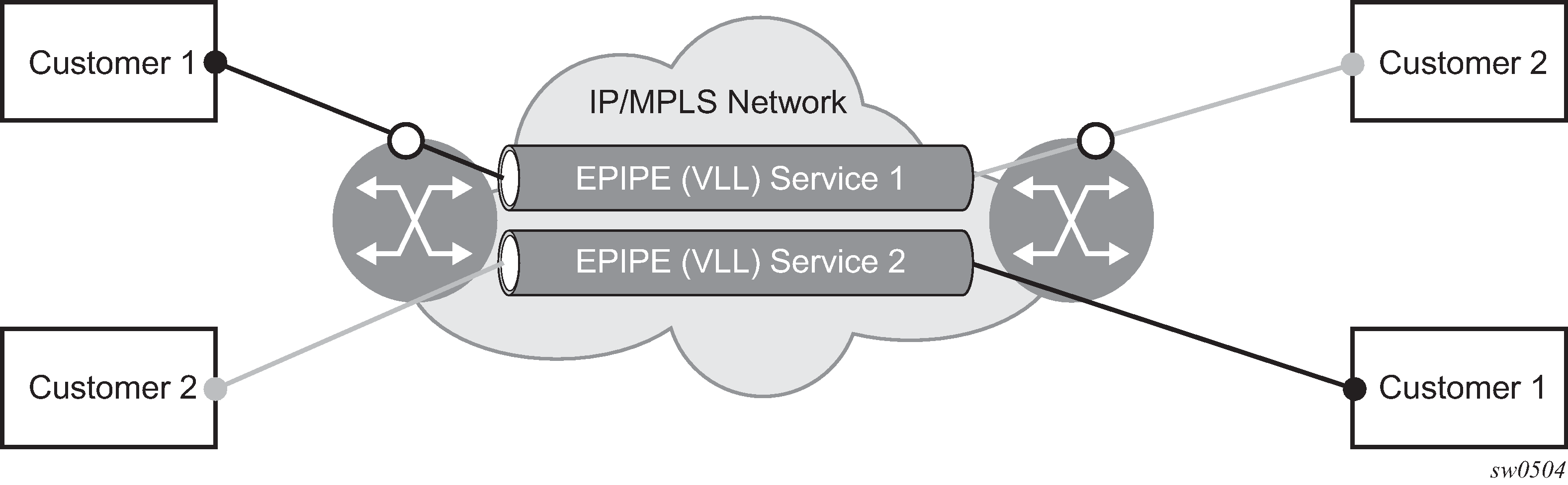
An Epipe service is a Layer 2 point-to-point service where the customer data is encapsulated and transported across a service provider's network. An Epipe service is completely transparent to the subscriber's data and protocols. The 7210 SAS Epipe service does not perform any MAC learning. A local Epipe service consists of two SAPs on the same node, whereas a distributed Epipe service consists of two SAPs on different nodes.
The following support is available on different platforms:
The 7210 SAS-D, 7210 SAS-Dxp, and 7210 SAS-K 2F1C2T support only local Epipe services. The 7210 SAS-D provide null, QinQ SAPs and dot1q SAPs to provide point-point Layer 2 local services.
The 7210 SAS-K 2F6C4T and 7210 SAS-K 3SFP+ 8C support both local and distributed Epipe services. The platforms provide null, QinQ SAPs and dot1q SAPs to provide a point-point Layer 2 local and distributed service. The platforms support the use of MPLS tunnels for distributed services.
Each SAP configuration includes a specific port on which service traffic enters the 7210 SAS router from the customer side (also called the access side). Each port is configured with an encapsulation type. If a port is configured with an IEEE 802.1Q (referred to as dot1q) encapsulation, a unique encapsulation value (ID) must be specified.
Local Epipe/VLL service using access or access-uplink ports on the 7210 SAS shows a local Epipe (VLL) service using access or access-uplink ports on a 7210 SAS. Distributed Epipe/ VLL service using network ports on 7210 SAS-K 2F6C4T and 7210 SAS-K 3SFP+ 8C shows a distributed Epipe (VLL) service using network ports on a 7210 SAS-K 2F6C4T or 7210 SAS-K 3SFP+ 8C.

Epipe oper state decoupling on 7210 SAS-K 2F1C2T, 7210 SAS-K 2F6C4T, and 7210 SAS-K 3SFP+ 8C
An Epipe service transitions to an operational state of down when only a single entity SAP or binding is active and the operational state of the mate is down or displays an equivalent state. The default behavior does not allow operators to validate the connectivity and measure performance metrics. With this feature an option is provided to allow operators to validate the connectivity and measure performance metrics of an Epipe service before the customer hand-off. The operator can also maintain performance and continuity measurement across their network regardless of the connectivity between the terminating node and the customer.
If the SAP between the operator and the customer enters a Oper Down state, the Epipe remains operationally up, so the results can continue to be collected uninterrupted. The operator receives applicable port or SAP alerts/alarms. This option is available only for the customer-facing SAP failures. If a network-facing SAP or spoke-SDP fails, the operational state of the Epipe service is set to down. That is, there is no option to hold the service in an UP state, if a network component fails.
The following functionality is supported:
Configuration under SAP is required to change the default behavior of the Epipe service in response to the SAP failure.
The user can create a SAP on a LAG where the LAG has no port members. In this case, the operator configures the ‟ignore-oper-state” on the SAP and the service remains operational. However, because no ports exist in the LAG member group, there is no extraction function that can be created. This feature protects against an established working configuration with full forwarding capabilities from failing to collect PM data. The user should shutdown their equipment and place the Epipe SAP in an operationally down state.
The SAP connecting the provider equipment to the customer is configured to hold the Epipe service status UP when the customer-facing SAP enters any failed state. Only one SAP per Epipe is allowed to be configured.
Any failure of the network entity (network SAP or SDP-binding) still causes the Epipe service to transition to operationally down.
As the service remains operationally up, all bindings should remain operationally up and should be able to receive and transmit data. The PW status represents the failed SAP in the LDP status message, but this does not prevent the data from using the PW as a transport, in or out. This is the same as LDP status messaging.
The SAP failure continues to trigger normal reactions, except the operational state of the service.
ETH-CFM PM measurement tools (DMM/SLM) can be used with the Up MEP on the failed SAP to collect performance metric. Additionally, CFM troubleshooting tools and connectivity (LBM, LTM, AIS, CCM) can be used and will function regularly.
ETH-CFM CCM processing and fault propagation does not change. Even when a SAP fails with the hold service UP configuration, CCM sets the interface status TLV to down.
VPLS services remain operationally UP until the final entity in the service enters a failed operational state. There are no changes to VPLS services and the change is specific to Epipe.
Dynamic Multi-Segment Pseudowire routing
The 7210 SAS-K 2F6C4T and 7210 SAS-K 3SFP+ 8C can only be configured as a T-PE node and not as an S-PE node.
The following sections describe the end-to-end solution with BGP PW-routing, assuming appropriate platforms are used for various functions.
Dynamic Multi-Segment Pseudowire (MS-PW) routing enables a complete MS-PW to be established, while only requiring per-pseudowire configuration on the T-PEs. No per-pseudowire configuration is required on the S-PEs. End-to-end signaling of the MS-PW is achieved using T-LDP, while multi-protocol BGP is used to advertise the T-PEs, allowing dynamic routing of the MS-PW through the intervening network of S-PEs. Dynamic MS-PWs are described in IETF draft-ietf-pwe3-dynamic-ms-pw-13.txt.
The following figure shows the operation of dynamic MS-PWs.
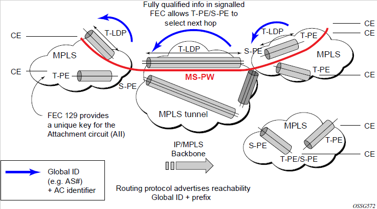
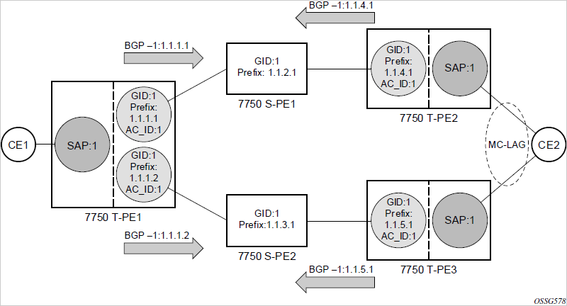
The FEC 129 AII Type 2 structure depicted in the following figure is used to identify each individual pseudowire endpoint.

A 4-byte global ID followed by a 4-byte prefix and a 4-byte attachment circuit ID are used to provide for hierarchical, independent allocation of addresses on a per service provider network basis. The first 8 bytes (global ID + prefix) may be used to identify each individual T-PE or S-PE as a loopback Layer 2 address.
This new AII type is mapped into the MS-PW BGP NLRI (a new BGP AFI of Layer 2 VPN, and SAFI for network layer reachability information for dynamic MS-PWs. As soon as a new T- PE is configured with a local prefix address of global id:prefix, pseudowire routing will proceed to advertise this new address to all the other T- PEs and S-PEs in the network, as shown in the following figure.

In step 1, a new T-PE (T-PE2) is configured with a local prefix.
Next, in steps 2 to 5, MP-BGP will use the NLRI for the MS-PW routing SAFI to advertise the location of the new T-PE to all the other PEs in the network. Alternatively, static routes may be configured on a per T-PE/S-PE basis to accommodate non-BGP PEs in the solution.
As a result, pseudowire routing tables for all the S-PEs and remote T-PEs are populated with the next hop to be used to reach T-PE2.
VLL services can then be established, as shown in the following figure.
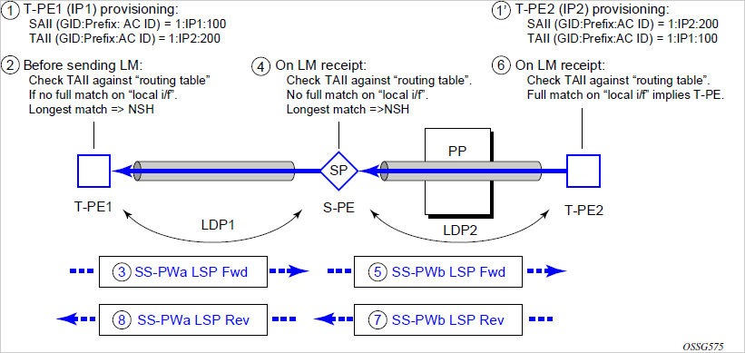
In step 1 and 1', the T-PEs are configured with the local and remote endpoint information, Source AII (SAII), Target AII (TAII). On the 7210 SAS, the AIIs are locally configured for each spoke-SDP, according to the model shown in Mapping of AII to SAP. Therefore, the 7210 SAS provides for a flexible mapping of AII to SAP. That is, the values used for the AII are through local configuration, and it is the context of the spoke-SDP that binds it to a specific SAP.

Before T-LDP signaling starts, the two T-PEs determine an active and passive relationship using the highest AII (comparing the configured SAII and TAII) or the configured precedence. Next, the active T-PE (in the IETF draft this is referred to as the source T-PE or ST-PE) checks the PW routing table to determine the next signaling hop for the configured TAII, using the longest match between the TAII and the entries in the PW routing table.
This signaling hop is then used to choose the T-LDP session to the chosen next-hop S-PE. Signaling proceeds through each subsequent S-PE using similar matching procedures to determine the next signaling hop. Otherwise, if a subsequent S-PE does not support dynamic MS-PW routing, and therefore uses a statically configured PW segment, the signaling of individual segments follows the procedures already implemented in the PW switching feature.
BGP can install a PW AII route in the PW routing table with ECMP next hops. However, when LDP needs to signal a PW with matching TAII, it will choose only one next hop from the available ECMP next hops. PW routing supports up to four ECMP paths for each destination.
The signaling of the forward path ends when the PE matches the TAII in the label mapping message with the SAII of a spoke-SDP bound to a local SAP. The signaling in the reverse direction can now be initiated, which follows the entries installed in the forward path. The PW routing tables are not consulted for the reverse path. This ensures that the reverse direction of the PW follows exactly the same set of S-PEs as the forward direction.
This solution can be used in either a MAN-WAN environment or in an inter-AS/inter-provider environment, as shown in the following figure.
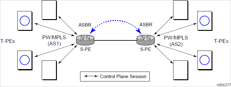
Data plane forwarding at the S-PEs uses pseudowire service label switching, as per the pseudowire switching feature.
MS-PW routing — pseudowire routing
The 7210 SAS-K 2F6C4T and 7210 SAS-K 3SFP+ 8C can only be configured as a T-PE node and not as an S-PE node.
The following sections describe the end-to-end solution with BGP PW-routing, assuming appropriate platforms are used for various functions.
Each S-PE and T-PE has a pseudowire routing table that contains a reference to the T-LDP session to use to signal to a set of next-hop S-PEs to reach a specific T-PE (or the T-PE if that is the next hop). For VLLs, this table contains aggregated AII Type 2 FECs and may be populated with routes that are learned through MP-BGP or that are statically configured.
MP-BGP is used to automatically distribute T-PE prefixes using the new MS-PW NLRI, or static routes can be used. The MS-PW NLRI is composed of a length, an 8-byte RD, a 4-byte global ID, a 4-byte local prefix, and (optionally) a 4-byte AC ID. Support for the MS-PW address family is configured in CLI under config>router>bgp>family ms-pw.
MS-PW routing parameters are configured in the config>service>pw-routing context.
To enable support for dynamic MS-PWs on a 7210 SAS node to be used as a T-PE or S-PE, a single, globally unique, S-PE ID, known as the S-PE address, is first configured under config>service>pw-routing on each 7210 SAS to be used as a T-PE or S-PE. The S-PE address has the format global-id:prefix. It is not possible to configure any local prefixes used for pseudowire routing or to configure spoke-SDPs using dynamic MS-PWs at a T-PE unless an S-PE address has already been configured. The S-PE address is used as the address of a node used to populate the switching point TLV in the LDP label mapping message and the pseudowire status notification sent for faults at an S-PE.
Each T-PE is also be configured with the following parameters:
Global ID
This is a 4-byte identifier that uniquely identifies an operator or the local network.
Local prefix
One or more local (Layer 2) prefixes (up to a maximum of 16), which are formatted in the style of a 4-octet IPv4 address. A local prefix identifies a T-PE or S-PE in the PW routing domain.
For each local prefix, at least one 8-byte route distinguisher (RD) can be configured. It is also possible to configure an optional BGP community attribute.
For each local prefix, BGP then advertises each global-id:prefix and unique RD and community pseudowire using the MS-PW NLRI, based on the aggregated FEC129 AII Type 2 and the Layer 2 VPN/PW routing AFI/SAFI 25/6, to each T-PE/S-PE that is a T-LDP neighbor, subject to local BGP policies.
The dynamic advertisement of each of these pseudowire routes is enabled for each prefix and RD, using the advertise-bgp command.
An export policy is also required to export MS-PW routes in MP-BGP. This can be done using a default policy, such as the following:
*A:lin-123>config>router>policy-options# info
----------------------------------------------
            policy-statement "ms-pw"
                default-action accept
                exit
            exit
----------------------------------------------
However, the preceding would export all routes. Nokia recommends enabling filtering per-family, as follows:
*A:lin-123>config>router>policy-options# info
----------------------------------------------
            policy-statement "to-mspw"
                entry 1
                    from
                        family ms-pw
                    exit
                    action accept
                    exit
                exit
            exit
----------------------------------------------
The following command is then added in the config>router>bgp context:
export "to-mspw"
The local-preference parameter for iBGP and BGP communities can be configured under such a policy.
MS-PW routing — static routing
In addition to support for BGP routing, static MS-PW routes may also be configured using the config>services>pw-routing>static-route command. Each static route comprises the target T-PE global ID and prefix, and the IP address of the T-LDP session to the next-hop S-PE or T-PE that should be used.
If a static route is set to 0, this represents the default route. If a static route exists to a specific T-PE, this is used in preference to any BGP route that may exist.
MS-PW routing — explicit paths
A set of default explicit routes to a remote T-PE or S-PE prefix may be configured on a T-PE under config>services>pw-routing using the path name command. Explicit paths are used to populate the explicit route TLV used by MS-PW T-LDP signaling. Only strict (fully qualified) explicit paths are supported.
It is possible to configure explicit paths independently of the configuration of BGP or static routing.
MS-PW routing — configuring VLLs using dynamic MS-PWs
One or more spoke-SDPs may be configured for distributed Epipe VLL services. Dynamic MS-PWs use FEC129 (also known as the Generalized ID FEC) with Attachment Individual Identifier (AII) Type 2 to identify the pseudowire, as opposed to FEC128 (also known as the PW ID FEC) used for traditional single segment pseudowires and for pseudowire switching. FEC129 spoke-SDPs are configured under the spoke-sdp-fec command in the CLI.
FEC129 AII Type 2 uses a Source Attachment Individual Identifier (SAII) and a Target Attachment Individual Identifier (TAII) to identify the end of a pseudowire at the T-PE. The SAII identifies the local end, while the TAII identifies the remote end. The SAII and TAII are each structured as follows:
global ID - a 4-byte identifier that uniquely identifies an operator or the local network
prefix - a 4-byte prefix, which should correspond to one of the local prefixes assigned under pw-routing
AC ID - a 4-byte identifier for this end of the pseudowire. This should be locally unique within the scope of the global-id:prefix
MS-PW routing — active/passive T-PE selection
Dynamic MS-PWs use single-sided signaling procedures with double-sided configuration; a fully qualified FEC must be configured at both endpoints. That is, one T-PE (the source T-PE: ST-PE) of the MS-PW initiates signaling for the MS-PW, while the other end (the terminating T-PE: TT-PE) passively waits for the label mapping message from the far-end. The TT-PE only responds with a label mapping message to set up the opposite direction of the MS-PW when it receives the label mapping from the ST-PE. By default, the 7210 SAS will determine which T-PE is the ST-PE (the active T-PE) and which is the TT-PE (the passive T-PE) automatically, based on comparing the SAII with the TAII as unsigned integers. The T-PE with SAII>TAII assumes the active role. However, it is possible to override this behavior using the signaling {master | auto} command under the spoke-sdp-fec. If master is selected at a specific T-PE, it will assume the active role. If a T-PE is at the endpoint of a spoke-SDP that is bound to an VLL SAP, and single-sided autoconfiguration is used, that endpoint is always passive. Therefore, signaling master should only be used when it is known that the far end will assume a passive behavior.
MS-PW routing — automatic endpoint configuration
Automatic endpoint configuration allows the configuration of an endpoint without specifying the TAII associated with that spoke-sdp-fec. It allows a single-sided provisioning model where an incoming label mapping message with a TAII that matches the SAII of that spoke-SDP can be automatically bound to that endpoint. This is useful in scenarios where a service provider needs to separate service configuration from the service activation phase.
Automatic endpoint configuration is supported required for Epipe VLL spoke-sdp-fec endpoints bound to a VLL SAP. It is configured using the spoke-sdp-fec>auto-config command, and excludes the TAII from the configuration. When autoconfiguration is used, the node assumes passive behavior from a point of view of T-LDP signaling. Therefore, the far-end T-PE must be configured for signaling master for that spoke-sdp-fec.
MS-PW routing — selecting a path for an MS-PW
Path selection for signaling occurs in the outbound direction (ST-PE to TT-PE) for an MS-PW. In the TT-PE to ST-PE direction, a label mapping message follows the reverse of the path of the outgoing label mapping.
A node can use explicit paths, static routes, or BGP routes to select the next hop S-PE or T-PE. The order of preference used in selecting these routes is:
explicit path
static route
BGP route
To use an explicit path for an MS-PW, an explicit path must have been configured in the config>services>pw-routing>path path-name context. The user must then configure the corresponding path path-name under the spoke-sdp-fec context.
If an explicit path name is not configured, the TT-PE or S-PE will perform a longest match lookup for a route (static if it exists, and BGP if not) to the next-hop S-PE or T-PE to reach the TAII.
Pseudowire routing chooses the MS-PW path in terms of the sequence of S-PEs to use to reach a specific T-PE. It does not select the SDP to use on each hop, which is instead determined at signaling time. When a label mapping is sent for a specific pseudowire segment, an LDP SDP will be used to reach the next-hop S-PE/T-PE if such an SDP exists. If not, and an RFC 3107 labeled BGP SDP is available, then that will be used. Otherwise, the label mapping will fail and a label release will be sent.
MS-PW routing — pseudowire templates
Dynamic MS-PWs support the use of the pseudowire template for specifying generic pseudowire parameters at the T-PE. The pseudowire template to use is configured in the spoke-sdp-fec>pw-template-bind policy-id context. Dynamic MS-PWs do not support the provisioned SDPs specified in the pseudowire template.
MS-PW routing — pseudowire redundancy
Pseudowire redundancy is supported on dynamic MS-PWs used for VLLs. It is configured in a similar manner to pseudowire redundancy on VLLs using FEC128, whereby each spoke-sdp FEC within an endpoint is configured with a unique SAII/TAII.
The following figure shows the use of pseudowire redundancy.
The following is a summary of the key points to consider in using pseudowire redundancy with dynamic MS-PWs:
Each MS-PW in the redundant set must have a unique SAII/TAII set and is signaled separately. The primary pseudowire is configured in the spoke-sdp-fec>primary context.
Each MS-PW in the redundant set should use a diverse path (from the point of view of the S-PEs traversed) from every other MS-PW in that set, if path diversity is possible in a specific network topology. There are a number of possible ways to achieve this:
Configure an explicit path for each MS-PW.
Allow BGP routing to automatically determine diverse paths using BGP policies applied to different local prefixes assigned to the primary and standby MS-PWs.
Provide path diversity for each primary pseudowire through the use of a BGP RD.
If the primary MS-PW fails, fail-over to a standby MS-PW, as per the normal pseudowire redundancy procedures. A configurable retry timer for the failed primary MS-PW is then started. When the timer expires, attempt to reestablish the primary MS-PW using its original path, up to a maximum number of attempts as per the retry count parameter. The T-PE may then optionally revert to the primary MS-PW on successful reestablishment.
Since the SDP ID is determined dynamically at signaling time, it cannot be used as a tie breaker to choose the primary MS-PW between multiple MS-PWs of the same precedence. The user should therefore explicitly configure the precedence values to determine which MS-PW is active in the final selection.
MS-PW routing — VCCV OAM for dynamic MS-PWs
The primary difference between dynamic MS-PWs and those using FEC128 is support for FEC129 AII type 2. As in PW switching, VCCV on dynamic MS-PWs requires the use of the VCCV control word on the pseudowire. Both the vccv-ping and vccv-trace commands support dynamic MS-PWs.
MS-PW routing — VCCV-ping on dynamic MS-PWs
VCCV-ping supports the use of FEC129 AII type 2 in the target FEC stack of the ping echo request message. The FEC to use in the echo request message is derived in one of two ways: either the user can explicitly specify the SAII and TAII to use, or the user can specify only the spoke-sdp-fec-id of the MS-PW in the vccv-ping command.
If the SAII:TAII is entered by the user in the vccv-ping command, those values are used for the vccv-ping echo request. However, their order is reversed before being sent, so that they match the order for the downstream FEC element for an S-PE, or the locally configured SAII:TAII for a remote T-PE of that MS-PW.
If SAII:TAII is entered in addition to the spoke-sdp-fec-id, the system will verify the entered values against the values stored in the context for that spoke-sdp-fec-id. The use of spoke-sdp-fec-id in vccv-ping is only applicable at T-PE nodes, because it is not configured for a specific MS-PW at S-PE nodes.
If the SAII:TAII is not entered by the user, and if a switching point TLV was received in the initial label mapping message for the reverse direction of the MS-PW (with respect to the sending PE), the SAII:TAII to use in the target FEC stack of the vccv-ping echo request message is derived by parsing that TLV, based on the user-specified TTL (or a TTL of 255 if none is specified). In this case, the order of the SAII:TAII in the switching point TLV is maintained for the vccv-ping echo request message.
If no pseudowire switching point TLV was received, the SAII:TAII values to use for the vccv-ping echo request are derived from the MS-PW context, but their order is reversed before being sent, so that they match the order for the downstream FEC element for an S-PE, or the locally configured SAII:TAII for a remote T-PE of that MS-PW.
MS-PW routing — VCCV-trace on dynamic MS-PWs
The 7210 SAS supports the MS-PW path trace mode of operation for VCCV-trace, as per pseudowire switching, but using FEC129 AII type 2. As in the case of VCCV-ping, the SAII:TAII used in the vccv-trace echo request message sent from the T-PE or S-PE, from which the vccv-trace command is executed, is specified by the user or derived from the context of the MS-PW.
The use of spoke-sdp-fec-id in vccv-trace is only applicable at T-PE nodes, because it is not configured for a specific MS-PW at S-PE nodes.
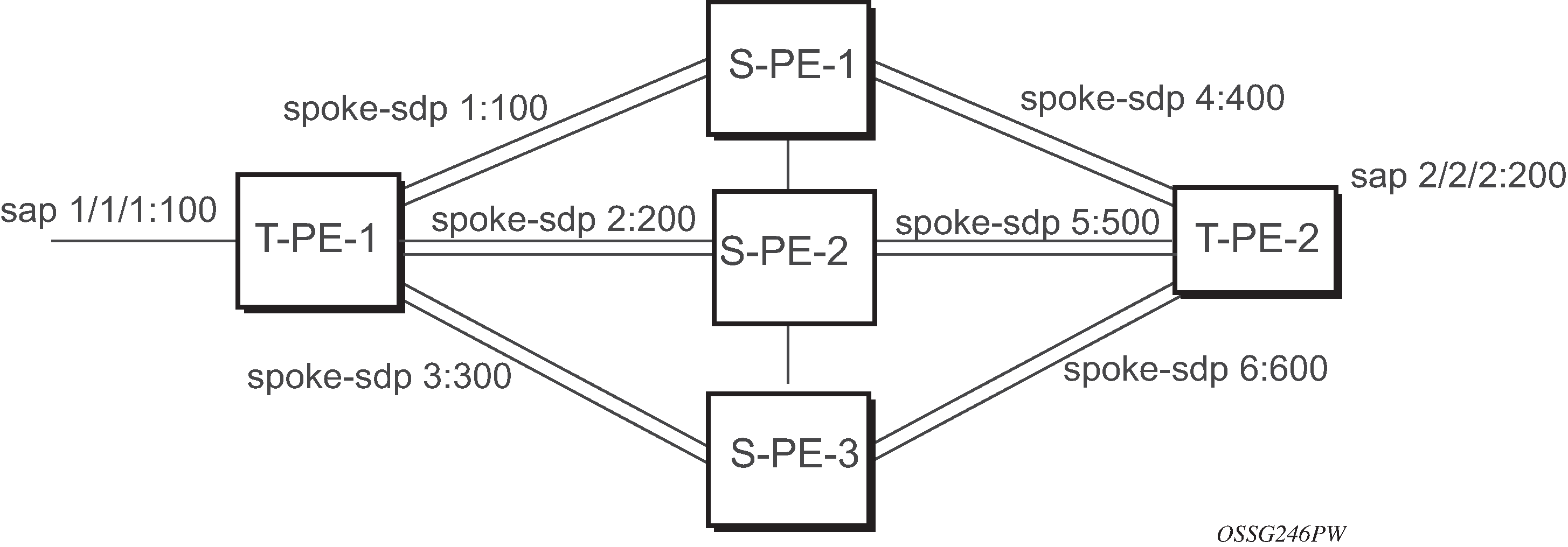
MS-PW routing — example dynamic MS-PW configuration
This section presents an example of how to configure dynamic MS-PWs for a VLL service between a set of 7210 SAS nodes. The network consists of two 7210 SAS T-PEs and two 7210 playing the role of S-PEs, as shown in the following figure. Each 7210 peers with its neighbor using LDP and BGP.
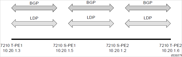
The example uses BGP to route dynamic MS-PWs and T-LDP to signal them. Therefore, each node must be configured to support the MS-PW address family under BGP, and BGP and LDP peerings must be established between the T-PEs. The appropriate BGP export policies must also be configured.
Finally, pseudowire routing must be configured on each node. This includes an S-PE address for every participating node, and one or more local prefixes on the T-PEs. MS-PW paths and static routes may also be configured.
When this routing and signaling infrastructure is established, spoke-sdp-fecs can be configured on each of the T-PEs.
config
   router
      ldp
         targeted-session
            peer 10.20.1.5
            exit
         exit
      policy-options
         begin
         policy-statement "exportMsPw"
            entry 10
               from
                  family ms-pw
               exit
               action accept
               exit
            exit
         exit
         commit
      exit
      bgp
         family ms-pw
         connect-retry 1
         min-route-advertisement 1
         export "exportMsPw"
         rapid-withdrawal
         group "ebgp"
            neighbor 10.20.1.5
               multihop 255
               peer-as 200
            exit
         exit
     exit
config
   service
      pw-routing
         spe-address 3:10.20.1.3
         local-prefix 3:10.20.1.3 create
         exit
         path "path1_to_F" create
            hop 1 10.20.1.5
            hop 2 10.20.1.2
            no shutdown
        exit
     exit
     epipe 1 customer 1 vpn 1 create
        description "Default epipe
             description for service id 1"
        service-mtu 1400
        service-name "XYZ Epipe 1"
        sap 2/1/1:1 create
        exit
        spoke-sdp-fec 1 fec 129 aii-type 2 create
           retry-timer 10
           retry-count 10
           saii-type2 3:10.20.1.3:1
           taii-type2 6:10.20.1.6:1
           no shutdown
        exit
        no shutdown
     exit
config
   router
      ldp
         targeted-session
            peer 10.20.1.2
            exit
         exit
         …
      policy-options
         begin
         policy-statement "exportMsPw"
            entry 10
               from
                  family ms-pw
               exit
               action accept
               exit
            exit
         exit
         commit
      exit

      bgp
         family ms-pw
         connect-retry 1
         min-route-advertisement 1
         export "exportMsPw"
         rapid-withdrawal
         group "ebgp"
            neighbor 10.20.1.2
               multihop 255
               peer-as 300
            exit
         exit
     exit
config
   service
      pw-routing
         spe-address 6:10.20.1.6
         local-prefix 6:10.20.1.6 create
         exit
         path "path1_to_F" create
            hop 1 10.20.1.2
            hop 2 10.20.1.5
            no shutdown
        exit
     exit
     epipe 1 customer 1 vpn 1 create
        description "Default epipe
             description for service id 1"
service-mtu 1400
        service-name "XYZ Epipe 1"
        sap 1/1/3:1 create
        exit
        spoke-sdp-fec 1 fec 129 aii-type 2 create
           retry-timer 10
           retry-count 10
           saii-type2 6:10.20.1.6:1
           taii-type2 3:10.20.1.3:1
           no shutdown
        exit
        no shutdown
     exit
Master-slave operation
7210 SAS devices support only the standby-signaling-master option. The 7210 SAS does not support the CLI command standby-signaling-slave. In the following description, reference to the standby-signaling-slave command is only used to describe the solution. The 7210 SAS can be used only where standby-signaling-master is used in the following example.
This section describes a mechanism in which one end on a pseudowire (the ‟master”) dictates the active PW selection, which is followed by the other end of the PW (the ‟slave”). This mechanism and associated terminology is specified in RFC 6870.
This section describes master-slave pseudowire redundancy. This redundancy adds the ability for the remote peer to react to the pseudowire standby status notification, even if only one spoke-SDP terminates on the VLL endpoint on the remote peer, by blocking the transmit (Tx) direction of a VLL spoke-SDP when the far-end PE signals standby. This solution enables the blocking of the Tx direction of a VLL spoke-SDP at both master and slave endpoints when standby is signaled by the master endpoint. This satisfies a majority of deployments where bidirectional blocking of the forwarding on a standby spoke-SDP is required.
Master-slave pseudowire redundancy shows the operation of master-slave pseudowire redundancy. In this scenario, an Epipe service is provided between CE1 and CE2. CE2 is dual-homed to PE2 and PE3, and therefore PE1 is dual-homed to PE2 and PE3 using Epipe spoke-SDPs. The objective of this feature is to ensure that only one pseudowire is used for forwarding in both directions by PE1, PE2, and PE3, in the absence of a native dual homing protocol between CE2 and PE2/PE3, such as MC-LAG. In normal operating conditions (the SAPs on PE2 and PE3 toward CE2 are both up and there are no defects on the ACs to CE2), PE2 and PE3 cannot choose which spoke-SDP to forward on based on the status of the AC redundancy protocol.

Master-slave pseudowire redundancy adds the ability for the remote peer to react to the pseudowire standby status notification, even if only one spoke-SDP terminates on the VLL endpoint on the remote peer. When the CLI command standby-signaling-slave is enabled at the spoke-SDP or explicit endpoint level in PE2 and PE3, any spoke-SDP for which the remote peer signals PW FWD standby will be blocked in the transmit direction.
This is achieved as follows. The standby-signaling-master state is activated on the VLL endpoint in PE1. In this case, a spoke-SDP is blocked in the transmit direction at this master endpoint if it is either in operDown state, or it has lower precedence than the highest precedence spoke-SDP, or the specific peer PE signals one of the following pseudowire status bits:
Pseudowire not forwarding (0x01)
SAP (ingress) receive fault (0x02)
SAP (egress) transmit fault (0x04)
SDP binding (ingress) receive fault (0x08)
SDP binding (egress) transmit fault (0x10)
That the specific spoke-SDP has been blocked will be signaled to the LDP peer through the pseudowire status bit (PW FWD standby (0x20)). This will prevent traffic being sent over this spoke-SDP by the remote peer, but only in case that remote peer supports and reacts to pseudowire status notification. Previously, this applied only if the spoke-SDP terminated on an IES, VPRN, or VPLS. However, if standby-signaling-slave is enabled at the remote VLL endpoint then the Tx direction of the spoke-SDP will also be blocked, according to the rules in PW redundancy — operation of master-slave pseudowire redundancy with existing scenarios.
Although master-slave operation provides bidirectional blocking of a standby spoke-SDP during steady-state conditions, it is possible that the Tx directions of more than one slave endpoint can be active for transient periods during a fail-over operation. This is due to slave endpoints transitioning a spoke-SDP from standby to active receiving or processing a pseudowire preferential forwarding status message before those transitioning a spoke-SDP to standby.
This transient condition is most likely when a forced switch-over is performed, or the relative preferences of the spoke-SDPs are changed, or the active spoke-SDP is shutdown at the master endpoint. During this period, loops of unknown traffic may be observed. Fail-overs due to common network faults that can occur during normal operation, a failure of connectivity on the path of the spoke-SDP or the SAP, would not result in such loops in the datapath.
PW redundancy — operation of master-slave pseudowire redundancy with existing scenarios
This section describes how master-slave pseudowire redundancy could operate.
PW redundancy — VLL resilience
The following figure shows a VLL resilience path example. An sample configuration follows.

A revert-time value of zero (default) means that the VLL path will be switched back to the primary immediately after it comes back up.
PE1
     configure service epipe 1
     endpoint X
     exit
     endpoint Y
     revert-time 0
     standby-signaling-master
     exit
     sap 1/1/1:100 endpoint X
     spoke-sdp 1:100 endpoint Y
precedence primary
     spoke-sdp 2:200 endpoint Y
precedence 1
PE2
configure service epipe 1
     endpoint X
     exit
     sap 2/2/2:200 endpoint X
     spoke-sdp 1:100
          standby-signaling-slave
PE3
configure service epipe 1
     endpoint X
     exit
     sap 3/3/3:300 endpoint X
     spoke-sdp 2:200
          standby-signaling-slave
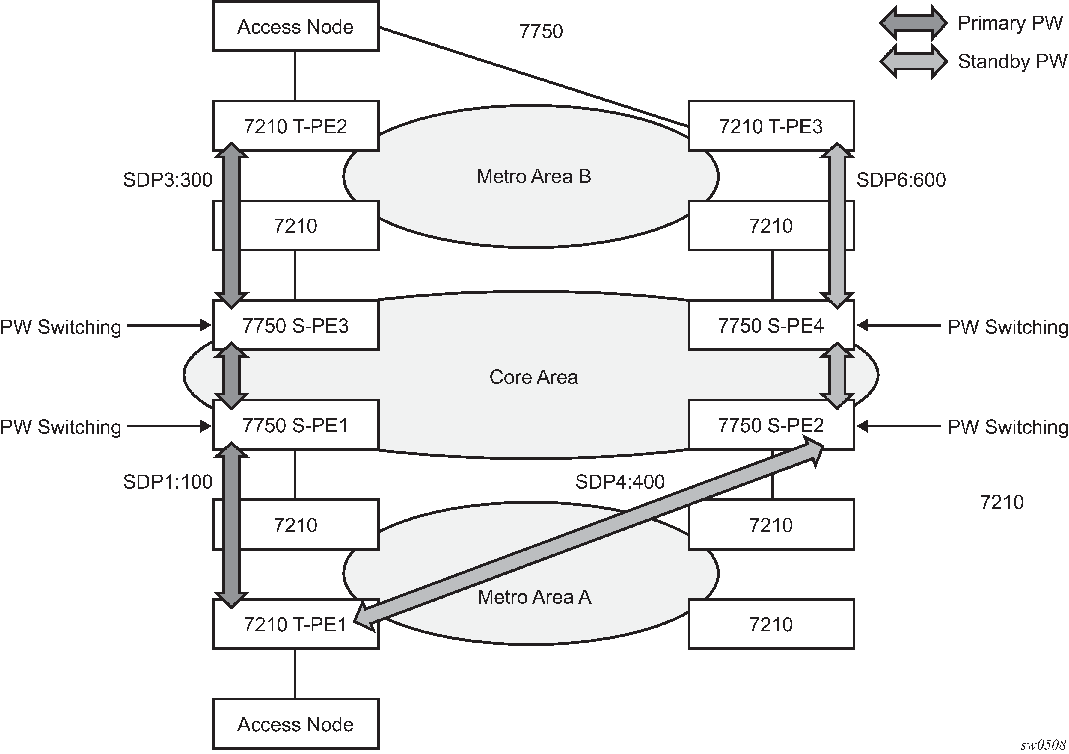
VLL resilience for a switched pseudowire path
The following figure shows the use of both pseudowire redundancy and pseudowire switching to provide a resilient VLL service across multiple IGP areas in a provider network.
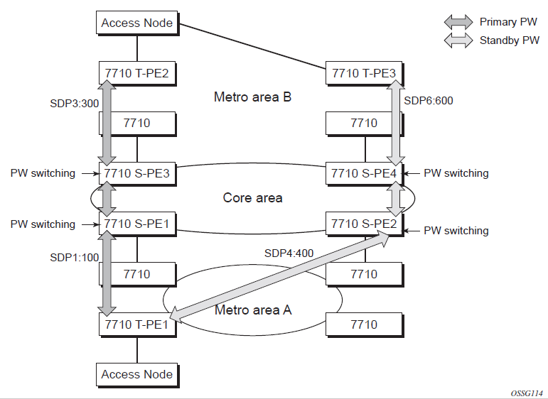
Pseudowire switching is a method for scaling a large network of VLL or VPLS services by removing the need for a full mesh of T-LDP sessions between the PE nodes as the number of these nodes grows over time.
As in the application in VLL resilience with two destination PE nodes, the T-PE1 node switches the path of a VLL to a secondary standby pseudowire, in the case of a network-side failure causing the VLL binding status to be down or if T-PE2 notified it that the remote SAP went down. This application requires that pseudowire status notification messages generated by either a T-PE node or a S-PE node be processed and relayed by the S-PE nodes.
It is possible that the secondary pseudowire path terminates on the same target PE as the primary; for example, T-PE2. This provides protection against network-side failures, but not against a remote SAP failure.
When the target destination PE for the primary and secondary pseudowires is the same, T-PE1 will not switch the VLL path onto the secondary pseudowire upon receipt of a pseudowire status notification indicating that the remote SAP is down. This occurs because the status notification is sent over both the primary and secondary pseudowires. However, the status notification on the primary pseudowire may arrive earlier than the one on the secondary pseudowire due to the differential delay between the paths. This will cause T-PE1 to switch the path of the VLL to the secondary standby pseudowire and remain there until the status notification is cleared. At that time, the VLL path is switched back to the primary pseudowire due to the revertive behavior operation. The path will not switch back to a secondary path when it comes up, even if it has a higher precedence than the currently active secondary path.
PW redundancy — VLL resilience for a switched PW path
The 7210 SAS-K 2F6C4T and 7210 SAS-K 3SFP+ 8C can only be configured as a T-PE node and not as an S-PE node.
VC-switching is not supported on the 7210 SAS-Dxp, 7210 SAS-K 2F1C2T, 7210 SAS-K 2F6C4T, and 7210 SAS-K 3SFP+ 8C.
The following figure shows a VLL resilience for a switched pseudowire path example. A sample configuration follows.

Configuration
T-PE1
     configure service epipe 1
     endpoint X
     exit
     endpoint Y
     revert-time 100
standby-signaling-master
     exit
     sap 1/1/1:100 endpoint X
     spoke-sdp 1:100 endpoint Y
          precedence primary
     spoke-sdp 2:200 endpoint Y
          precedence 1
     spoke-sdp 3:300 endpoint Y
          precedence 1

T-PE2
configure service epipe 1
     endpoint X
     exit
     endpoint Y
     revert-time 100
     standby-signaling-slave
     exit
     sap 2/2/2:200 endpoint X
     spoke-sdp 4:400 endpoint Y
          precedence primary
     spoke-sdp 5:500 endpoint Y
          precedence 1
     spoke-sdp 6:600 endpoint Y
          precedence 1
S-PE1
VC switching indicates a VC cross-connect so that the service manager does not signal the VC label mapping immediately, but will put this into passive mode.
configure service epipe 1 vc-switching
     spoke-sdp 1:100
     spoke-sdp 4:400
Access node resilience using MC-LAG and pseudowire redundancy
The following figure shows the use of both Multi-Chassis Link Aggregation (MC-LAG) in the access network and pseudowire redundancy in the core network to provide a resilient end-to-end VLL service to the customers.
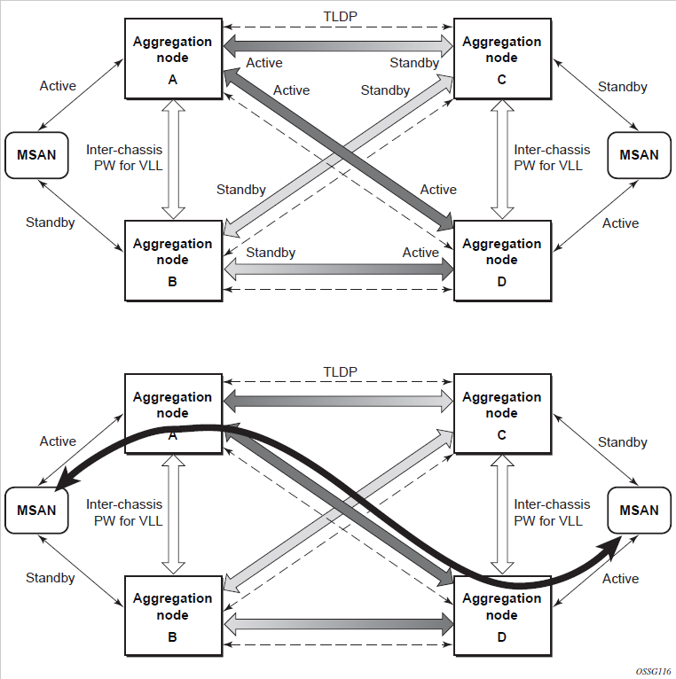
In this application, a pseudowire status bit of active or standby indicates the status of the SAP in the MC-LAG instance in the 7210 SAS aggregation node. All spoke-SDPs are of secondary type and there is no use of a primary pseudowire type in this mode of operation.
Node A is in the active state according to its local MC-LAG instance, and therefore advertises active status notification messages to both its peer pseudowire nodes; for example, nodes C and D. Node D performs the same operation. Node B is in the standby state according to the status of the SAP in its local MC-LAG instance, and therefore advertises standby status notification messages to both nodes C and D. Node C performs the same operation.
The 7210 SAS node selects a pseudowire as the active path for forwarding packets when both the local pseudowire status and the received remote pseudowire status indicate active status. However, a 7210 SAS device in standby status according to the SAP in its local MC-LAG instance is capable of processing packets for a VLL service received over any of the pseudowires that are up. This is to avoid black holing of user traffic during transitions.
The 7210 SAS standby node forwards these packets to the active node via the Inter-Chassis Backup (ICB) pseudowire for this VLL service. An ICB is a spoke-SDP used by an MC-LAG node to back up an MC-LAG SAP during transitions. The same ICB can also be used by the peer MC-LAG node to protect against network failures causing the active pseudowire to go down.
At configuration time, the user specifies a precedence parameter for each of the pseudowires that are part of the redundancy set as described in the application. A 7210 SAS node uses this to select which pseudowire to forward packet to in case both pseudowires show active/active for the local/remote status during transitions.
Only VLL service of type Epipe is supported in this application. Also, ICB spoke-SDP can only be added to the SAP side of the VLL cross-connect if the SAP is configured on an MC-LAG instance.
Epipe pseudowire switching on 7210 SAS-K 2F6C4T and 7210 SAS-K 3SFP+ 8C
The 7210 SAS-K 2F6C4T and 7210 SAS-K 3SFP+ 8C can only be configured as T-PE nodes and not as S-PE nodes. In this section, references to S-PE nodes refer to other products in the Nokia IP product family that support S-PE functionality.
The pseudowire switching feature provides the user with the ability to create a VLL service by cross-connecting two spoke-SDPs. This feature allows the scaling of VLL and VPLS services in a large network in which the otherwise full mesh of PE devices would require thousands of Targeted LDP (T-LDP) sessions per PE node.
Services with one SAP and one spoke-SDP are created on the PE; however, the target destination of the SDP is the pseudowire switching node instead of the remote PE. In addition, the user configures a VLL service on the pseudowire switching node using the two SDPs.
The pseudowire switching node (that is, S-PE node) acts in a passive role with respect to signaling of the pseudowires. It waits until one or both PEs (that is, T-PEs) sends the label mapping message before relaying it to the other PE. This is because it needs to pass the interface parameters of each PE to the other.
A pseudowire switching point TLV is inserted by the switching pseudowire to record its system address when relaying the label mapping message. This TLV is useful in a few situations:
It allows for troubleshooting of the path of the pseudowire, especially if multiple pseudowire switching points exist between the two PEs.
It helps in loop detection of the T-LDP signaling messages where a switching point would receive back a label mapping message it had already relayed.
It is inserted in pseudowire status notification messages when they are sent end-to-end or from a pseudowire switching node toward a destination PE.
Pseudowire OAM is supported for the manual switching pseudowires and allows the pseudowire switching node to relay end-to-end pseudowire status notification messages between the two PEs. The pseudowire switching node can generate a pseudowire status and send it to one or both PEs by including its system address in the pseudowire switching point TLV. This allows a PE to identify the origin of the pseudowire status notification message.
In the following example, the user configures a regular Epipe VLL service PE1 and PE2 (acting as T-PE nodes). These services each consist of a SAP and a spoke-SDP. However, the target destination of the SDP is not the remote PE but the pseudowire switching node. In addition, the user configures an Epipe VLL service on the pseudowire switching node using the two SDPs.
|7210 SAS-K 2F6C4T PE1 [T-PE node] (Epipe)|---sdp 2:10---
|7450 ESS, 7750 SR, and 7950 XRS PW SW [S-PE node] (Epipe)|---sdp 7:15---|7210 SAS-
K12 PE2 [T-PE node] (Epipe)|
Configuration examples can be found in ‟Configuring Two VLL Paths Terminating on T-PE2”.
Pseudowire switching with protection
Pseudowire switching scales VLL and VPLS services over a multi-area network by removing the need for a full mesh of targeted LDP sessions between PE nodes. This illustrates the use of pseudowire redundancy to provide a scalable and resilient VLL service across multiple IGP areas in a provider network.
In the network in VLL resilience with pseudowire redundancy and switching, PE nodes act as leading nodes and pseudowire switching nodes act as followers for the purpose of pseudowire signaling. A switching node must pass the SAP interface parameters of each PE to the other. T-PE1 sends a label mapping message for the Layer 2 FEC to the peer pseudowire switching node; for example, S-PE1.
It will include the SAP interface parameters, such as MTU, in the label mapping message. S-PE1 checks the FEC against the local information and if a match exists, it appends the optional pseudowire switching point TLV to the FEC TLV in which it records its system address. T-PE1 then relays the label mapping message to S-PE2. S-PE2 performs similar operations and forwards a label mapping message to T-PE2.
The same procedures are followed for the label mapping message in the reverse direction; for example, from T-PE2 to T-PE1. S-PE1 and SPE2 will affect the spoke-SDP cross-connect only when both directions of the pseudowire have been signaled and matched.
The pseudowire switching TLV is useful in a few situations. First, it allows for troubleshooting of the path of the pseudowire especially if multiple pseudowire switching points exist between the two T-PE nodes. Second, it helps in loop detection of the T-LDP signaling messages where a switching point receives back a label mapping message it already relayed. Finally, it can be inserted in pseudowire status messages when they are sent from a pseudowire switching node toward a destination PE.
Pseudowire status messages can be generated by the T-PE nodes and/or the S-PE nodes. Pseudowire status messages received by a switching node are processed, then passed on to the next-hop. An S-PE node appends the optional pseudowire switching TLV, with its system address added to it, to the FEC in the pseudowire status notification message, only if it originated the message or the message was received with the TLV in it. Otherwise, the message was originated by a TPE node and the S-PE should process and pass the message without changes except for the VCID value in the FEC TLV.
Pseudowire switching behavior
In the network in VLL resilience with pseudowire redundancy and switching, PE nodes act as leading nodes and pseudowire switching nodes act as followers for the purpose of pseudowire signaling. A switching node will need to pass the SAP interface parameters of each PE to the other. T-PE1 sends a label mapping message for the Layer 2 FEC to the peer pseudowire switching node; for example, S-PE1.
It will include the SAP interface parameters, such as MTU, in the label mapping message. S-PE1 checks the FEC against the local information and if a match exists, it appends the optional pseudowire switching point TLV to the FEC TLV in which it records its system address. TPE1 then relays the label mapping message to S-PE2. S-PE2 performs similar operations and forwards a label mapping message to T-PE2.
The same procedures are followed for the label mapping message in the reverse direction; for example, from T-PE2 to T-PE1. S-PE1 and S-PE2 will affect the spoke-SDP cross-connect only when both directions of the pseudowire have been signaled and matched.
Pseudowire status notification messages can be generated by the T-PE nodes and/ or the S-PE nodes. Pseudowire status notification messages received by a switching node are processed, then passed on to the next hop. An S-PE node appends the optional pseudowire switching TLV, with its system address added to it, to the FEC in the pseudowire status notification message only if it originated the message or the message was received with the TLV in it. Otherwise, it means the message was originated by a T-PE node and the S-PE should process and pass the message without changes except for the VC ID value in the FEC TLV.
The merging of the received T-LDP status notification message and the local status for the spoke-SDPs from the service manager at a PE complies with the following rules:
When the local status for both spoke-SDPs is up, the S-PE passes any received SAP or SDP-binding generated status notification message unchanged; for example, the status notification TLV is unchanged but the VC ID in the FEC TLV is set to the value of the pseudowire segment to the next hop.
When the local operational status for any of the spoke-SDPs is down, the S-PE always sends SDP-binding down status bits, regardless of whether the received status bits from the remote node indicated SAP up/down or SDP-binding up/down.
Pseudowire switching TLV
The following figure shows the format of the pseudowire switching TLV.
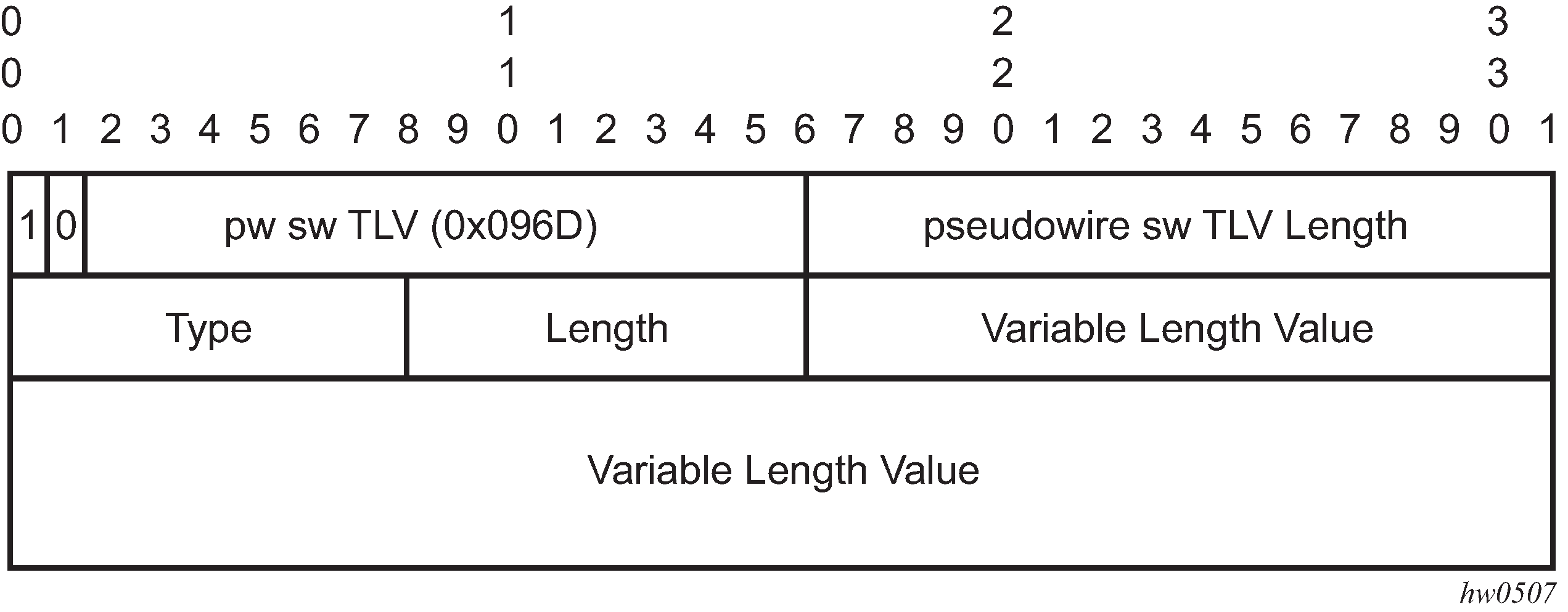
PW sw TLV Length - Specifies the total length of all the following pseudowire switching point TLV fields in octets:
Type - encodes how the value field is to be interpreted
Length - specifies the length of the value field in octets
Value - octet string of length octets that encodes information to be interpreted as specified by the type field
Pseudowire switching point sub-TLVs
The following are details specific to pseudowire switching point sub-TLVs:
pseudowire ID of last pseudowire segment traversed - this sub-TLV type contains a pseudowire ID in the format of the pseudowire ID
pseudowire switching point description string - an optional description string of text up to 80 characters
IP address of pseudowire switching point
The IP V4 or V6 address of the pseudowire switching point. This is an optional sub TLV:
MH VCCV capability indication
Pseudowire redundancy
Pseudowire redundancy provides the ability to protect a pseudowire with a preprovisioned secondary standby pseudowire and to switch traffic over to the secondary standby pseudowire in case of a SAP and/or network failure condition. Pseudowires are redundant due to the SDP redundancy mechanism. For example, if the SDP is an RSVP LSP and is protected by a secondary standby path and/or by Fast Reroute (FRR) paths, the pseudowire is also protected. However, there are a couple of applications in which SDP redundancy does not protect the end-to-end pseudowire path:
There are two different destination PE nodes for the same VLL service. The main use case is the provision of dual-homing of a CPE or access node to two PE nodes located in different POPs. The other use case is the provision of a pair of active and standby BRAS nodes, or active and standby links to the same BRAS node, to provide service resiliency to broadband service subscribers.
The pseudowire path is switched in the middle of the network and the pseudowire switching node fails.
Pseudowire and VPLS link redundancy extends link-level resiliency for pseudowires and VPLS to protect critical network paths against physical link or node failures. These innovations enable the virtualization of redundant paths across the metro or core IP network to provide seamless and transparent fail-over for point-to-point and multi-point connections and services. When deployed with multi-chassis LAG, the path for return traffic is maintained through the pseudowire or VPLS switchover, which enables carriers to deliver ‟always on” services across their IP/MPLS networks.
VLL service resilience with pseudowire on 7210 SAS-K 3SFP+ 8C
The following sections describe VLL resilience.
VLL resilience with two destination PE nodes
The following figure shows the application of pseudowire redundancy to provide Ethernet VLL service resilience for broadband service subscribers accessing the broadband service on the service provider BRAS.
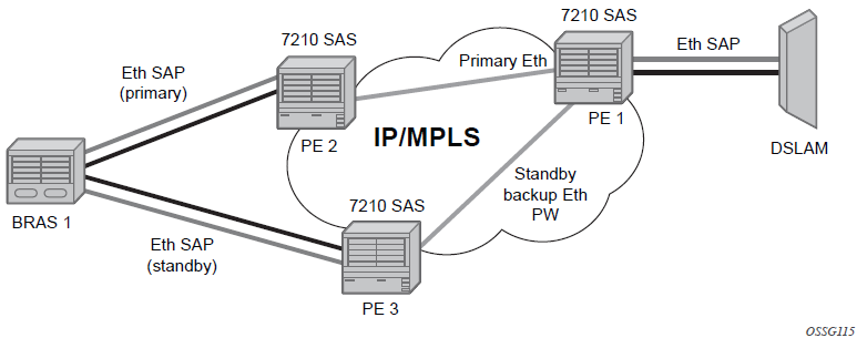
If the Ethernet SAP on PE2 fails, PE2 notifies PE1 of the failure by either withdrawing the primary pseudowire label it advertised or by sending a pseudowire status notification with the code set to indicate a SAP defect. PE1 will receive it and will immediately switch its local SAP to forward over the secondary standby spoke-SDP. To avoid black holing of in-flight packets during the switching of the path, PE1 will accept packets received from PE2 on the primary pseudowire while transmitting over the backup pseudowire. However, in other applications such as those described in Access node resilience using MC-LAG and pseudowire redundancy, it will be important to minimize service outage to end users.
When the SAP on PE2 is restored, PE2 updates the new status of the SAP by sending a new label mapping message for the same pseudowire FEC or by sending a pseudowire status notification message indicating that the SAP is back up. PE1 then starts a timer and reverts back to the primary at the expiry of the timer. By default, the timer is set to 0, which means PE1 reverts immediately. A special value of the timer (infinity) will mean that PE1 should never revert back to the primary pseudowire.
The behavior of the pseudowire redundancy feature is the same if PE1 detects or is notified of a network failure that brought the spoke-SDP operational status to down. The following are the events that will cause PE1 to trigger a switchover to the secondary standby pseudowire:
LDP peer (remote PE) node withdrew the pseudowire label.
T-LDP peer signaled a FEC status indicating a pseudowire failure or a remote SAP failure.
T-LDP session to the peer node times out.
SDP binding and VLL service went down as a result of a network failure condition, such as the SDP to peer node going operationally down.
The SDP type for the primary and secondary pseudowires need not be the same. That is, the user can protect a RSVP-TE based spoke-SDP with a LDP one. This provides the ability to route the path of the two pseudowires over different areas of the network.
The 7210 SAS routers support the ability to configure multiple secondary standby pseudowire paths. For example, PE1 uses the value of the configurable precedence parameter associated with each spoke-SDP to select the next available pseudowire path after the failure of the current active pseudowire (whether it is the primary or one of the secondary pseudowires). However, the revertive operation always switches the path of the VLL back to the primary pseudowire. There is no revertive operation between secondary paths, meaning that the path of the VLL will not be switched back to a secondary pseudowire of higher precedence when the latter comes back up again.
The 7210 SAS routers support the ability for a user-initiated manual switchover of the VLL path to the primary or any of the secondary be supported to divert user traffic in case of a planned outage, such as in node upgrade procedures.
On the 7210 SAS, this application is supported with Epipe Service.
Master-slave operation
This section describes a mechanism in which one end on a pseudowire (the ‟master”) dictates the active PW selection, which is followed by the other end of the PW (the ‟slave”). This mechanism and associated terminology is specified in RFC 6870.
This section describes master-slave pseudowire redundancy. It adds the ability for the remote peer to react to the pseudowire standby status notification, even if only one spoke-SDP terminates on the VLL endpoint on the remote peer, by blocking the transmit (Tx) direction of a VLL spoke-SDP when the far-end PE signals standby. This solution enables the blocking of the Tx direction of a VLL spoke-SDP at both master and slave endpoints when standby is signaled by the master endpoint. This approach satisfies a majority of deployments where bidirectional blocking of the forwarding on a standby spoke-SDP is required.
Master-slave pseudowire redundancy shows the operation of master-slave pseudowire redundancy. In this scenario, an Epipe service is provided between CE1 and CE2. CE2 is dual-homed to PE2 and PE3, and therefore PE1 is dual-homed to PE2 and PE3 using Epipe spoke-SDPs. The objectives of this feature is to ensure that only one pseudowire is used for forwarding in both directions by PE1, PE2 and PE3 in the absence of a native dual homing protocol between CE2 and PE2/PE3, such as MC-LAG. In normal operating conditions (the SAPs on PE2 and PE3 toward CE2 are both up and there are no defects on the ACs to CE2), PE2 and PE3 cannot choose which spoke-SDP to forward on based on the status of the AC redundancy protocol.
Master-slave pseudowire redundancy adds the ability for the remote peer to react to the pseudowire standby status notification, even if only one spoke-SDP terminates on the VLL endpoint on the remote peer. When the CLI command standby-signaling-slave is enabled at the spoke-SDP or explicit endpoint level in PE2 and PE3, then any spoke-SDP for which the remote peer signals PW FWD Standby will be blocked in the transmit direction.
This is achieved as follows. The standby-signaling-master state is activated on the VLL endpoint in PE1. In this case, a spoke-SDP is blocked in the transmit direction at this master endpoint if it is either in operDown state, or it has lower precedence than the highest precedence spoke-SDP, or the specific peer PE signals one of the following pseudowire status bits:
Pseudowire not forwarding (0x01)
SAP (ingress) receive fault (0x02)
SAP (egress) transmit fault (0x04)
SDP binding (ingress) receive fault (0x08)
SDP binding (egress) transmit fault (0x10)
The fact that the specific spoke-SDP has been blocked will be signaled to LDP peer through the pseudowire status bit (PW FWD Standby (0x20)). This will prevent traffic being sent over this spoke-SDP by the remote peer, but obviously only in case that remote peer supports and reacts to pseudowire status notification. Previously, this applied only if the spoke-SDP terminates on an IES, VPRN or VPLS. However, if standby-signaling-slave is enabled at the remote VLL endpoint then the Tx direction of the spoke-SDP will also be blocked, according to the rules in Operation of master-slave pseudowire redundancy with existing scenarios.
Although master-slave operation provides bidirectional blocking of a standby spoke-SDP during steady-state conditions, it is possible that the Tx directions of more than one slave endpoint can be active for transient periods during a fail-over operation. This is due to slave endpoints transitioning a spoke-SDP from standby to active receiving or processing a pseudowire preferential forwarding status message before those transitioning a spoke-SDP to standby. This transient condition is most likely when a forced switch-over is performed, or the relative preferences of the spoke-SDPs is changed, or the active spoke-SDP is shutdown at the master endpoint. During this period, loops of unknown traffic may be observed. Fail-overs due to common network faults that can occur during normal operation, a failure of connectivity on the path of the spoke-SDP or the SAP, would not result in such loops in the datapath.
Operation of master-slave pseudowire redundancy with existing scenarios
This section describes how master-slave pseudowire redundancy could operate.
The following figure shows a VLL resilience path example. An sample configuration follows.

A revert-time value of zero (default) means that the VLL path will be switched back to the primary immediately after it comes back up.
PE1
configure service epipe 1
endpoint X
exit
endpoint Y
   revert-time 0
   standby-signaling-master
   exit
   sap 1/1/1:100 endpoint X
   spoke-sdp 1:100 endpoint Y
precedence primary
   spoke-sdp 2:200 endpoint Y
precedence 1
PE2
configure service epipe 1
   endpoint X
   exit
   sap 2/2/2:200 endpoint X
   spoke-sdp 1:100
      standby-signaling-slave
PE3
configure service epipe 1
   endpoint X
   exit
   sap 3/3/3:300 endpoint X
   spoke-sdp 2:200
      standby-signaling-slave
VLL resilience for a switched pseudowire path
The following figure displays VLL resilience for a switched pseudowire path example. A sample configuration follows.
T-PE-1
configure service epipe 1
   endpoint X
   exit
   endpoint Y
   revert-time 100
   standby-signaling-master
   exit
   sap 1/1/1:100 endpoint X
   spoke-sdp 1:100 endpoint Y
      precedence primary
   spoke-sdp 2:200 endpoint Y
      precedence 1
   spoke-sdp 3:300 endpoint Y
      precedence 1

T-PE-2
configure service epipe 1
   endpoint X
   exit
   endpoint Y
   revert-time 100
   standby-signaling-slave
   exit
   sap 2/2/2:200 endpoint X
   spoke-sdp 4:400 endpoint Y
      precedence primary
   spoke-sdp 5:500 endpoint Y
      precedence 1
   spoke-sdp 6:600 endpoint Y
      precedence 1
S-PE-1
VC switching indicates a VC cross-connect so that the service manager does not signal the VC label mapping immediately but will put S-PE-1 into passive mode, as follows:
configure service epipe 1 vc-switching
   spoke-sdp 1:100
   spoke-sdp 4:400
Pseudowire redundancy service models
This section describes the various pseudowire redundancy scenarios as well as the algorithm used to select the active transmit object in a VLL endpoint.
The redundant VLL service model is described in the following section, Pseudowire redundancy — redundant VLL service model.
Pseudowire redundancy — redundant VLL service model
To implement pseudowire redundancy, a VLL service accommodates more than a single object on the SAP side and on the spoke-SDP side. The following figure shows the model for a redundant VLL service based on the concept of endpoints.

A VLL service supports, by default, two implicit endpoints managed internally by the system. Each endpoint can only have one object: a SAP or a spoke-SDP.
To add more objects, up to two explicitly named endpoints may be created per VLL service. The endpoint name is locally significant to the VLL service. They are referred to as endpoint X and endpoint Y shown in Redundant VLL endpoint objects.
Redundant VLL endpoint objects is just an example and the Y endpoint can also have a SAP or an ICB spoke-SDP. The following describes the four types of endpoint objects supported and the rules used when associating them with an endpoint of a VLL service:
SAP
There can only be a maximum of one SAP per VLL endpoint.
Primary spoke-SDP
The VLL service always uses this pseudowire and only switches to a secondary pseudowire when it is down. The VLL service switches the path to the primary pseudowire when it is back up. The user can configure a timer to delay reverting back to primary or to never revert. There can only be a maximum of one primary spoke-SDP per VLL endpoint.
Secondary spoke-SDP
There can be a maximum of four secondary spoke-SDPs per endpoint. The user can configure the precedence of a secondary pseudowire to indicate the order in which a secondary pseudowire is activated.
Inter-Chassis Backup (ICB) spoke-SDP
This is a special pseudowire used for MC-LAG and pseudowire redundancy application. Forwarding between ICBs is blocked on the same node. The user has to explicitly indicate that the spoke-SDP is an ICB at creation time. There are a few scenarios, as follows, where the user can configure the spoke-SDP as an ICB or as a regular spoke-SDP on a specific node. The CLI for those cases will indicate both options.
A VLL service endpoint can only use one active object to transmit at any specific time, but can receive from all endpoint objects.
An explicitly named endpoint can have a maximum of one SAP and one ICB. When a SAP is added to the endpoint, only one more object of type ICB spoke-SDP is allowed. The ICB spoke-SDP cannot be added to the endpoint if the SAP is not part of an MC-LAG instance. A SAP that is not part of an MC-LAG instance cannot be added to an endpoint that already has an ICB spoke-SDP.
An explicitly named endpoint, which does not have a SAP object, can have a maximum of four spoke-SDPs and can include any of the following:
a single primary spoke-SDP
one or many secondary spoke-SDPs with precedence
a single ICB spoke-SDP
Pseudowire redundancy — T-LDP status notification handling rules
Using Redundant VLL endpoint objects as a reference, the following are the rules for generating, processing, and merging T-LDP status notifications in VLL service with endpoints.
Any allowed combination of objects as specified in Pseudowire redundancy — redundant VLL service model can be used on endpoints X and Y.
The following sections refer to the specific combination objects in Redundant VLL endpoint objects as an example to describe the more general rules.
Processing endpoint SAP active/standby status bits
The advertised admin forwarding status of active/standby reflects the status of the local LAG SAP in the MC-LAG application. If the SAP is not part of an MC-LAG instance, the forwarding status of active is always advertised.
When the SAP in endpoint X is part of an MC-LAG instance, a node must send the T-LDP forwarding status bit of ‟SAP active/standby” over all Y endpoint spoke-SDPs, except the ICB spoke-SDP, whenever this status changes. The status bit sent over the ICB is always zero (active by default).
When the SAP in endpoint X is not part of an MC-LAG instance, the forwarding status sent over all Y endpoint spoke-SDPs should always be set to zero (active by default).
Processing and merging
Endpoint X is operationally up if at least one of its objects is operationally up. It is down if all its objects are operationally down.
If the SAP in endpoint X transitions locally to the down state, or receives a SAP down notification by SAP-specific OAM signal, the node must send T-LDP SAP down status bits on the Y endpoint ICB spoke-SDP only.
Ethernet SAP does not support SAP OAM protocol. All other SAP types cannot exist on the same endpoint as an ICB spoke-SDP since a non-Ethernet SAP cannot be part of an MC-LAG instance.
If the ICB spoke-SDP in endpoint X transitions locally to the down state, the node must send T-LDP SDP-binding down status bits on this spoke-SDP.
If the ICB spoke-SDP in endpoint X receives T-LDP SDP-binding down status bits or pseudowire not forwarding status bits, the node saves this status and takes no further action. The saved status is used for selecting the active transmit endpoint object.
If all objects in endpoint X have any of the following happen, the node must send status bits of SAP down over all Y endpoint spoke-SDPs, including the ICB:
transition locally to down state
receive a SAP down notification by remote T-LDP status bits
receive a SAP down notification by SAP-specific OAM signal
receive status bits of SDP-binding down
receive status bits of pseudowire not forwarding
Endpoint Y is operationally up if at least one of its objects is operationally up. It is down if all its objects are operationally down.
If a spoke-SDP in endpoint Y, including the ICB spoke-SDP, transitions locally to down state, the node must send T-LDP SDP-binding down status bits on this spoke-SDP.
If a spoke-SDP in endpoint Y, including the ICB spoke-SDP, receive any of the following, the node saves this status and takes no further action:
T-LDP SAP down status bits
T-LDP SDP-binding down status bits
status bits of pseudowire not forwarding
The saved status is used for selecting the active transmit endpoint object.
If all objects in endpoint Y, except the ICB spoke-SDP, have any of the following happen, the node must send status bits of SDP-binding down over the X endpoint ICB spoke-SDP only:
transition locally to down state
receive T-LDP SAP down status bits
receive T-LDP SDP-binding down status bits
receive status bits of pseudowire not forwarding
If all objects in endpoint Y have any of the following happen, the node must send status bits of SDP-binding down over the X endpoint ICB spoke-SDP, and must send a SAP down notification on the X endpoint SAP by the SAP-specific OAM signal, if applicable:
transition locally to down state
receive T-LDP SAP down status bits
receive T-LDP SDP-binding down status bits
receive status bits of pseudowire not forwarding
An Ethernet SAP does not support signaling status notifications.
MPLS entropy label and hash label
MPLS entropy label (RFC 6790) and the Flow Aware Transport label (known as the hash label) (RFC 6391) allow LSR nodes in a network to load-balance labeled packets in a much more granular fashion than allowed by hashing on the standard label stack. For more information, see the 7210 SAS-K 2F6C4T, K 3SFP+ 8C MPLS Guide.
The 7210 SAS-K 2F6C4T and 7210 SAS-K 3SFP+ 8C do not support MPLS entropy label or hash label.
VLL service considerations
This section describes various general service features and any special capabilities or considerations as they relate to VLL services.
SDPs
The most basic SDPs must have the following:
locally unique SDP identification (ID) number
system IP address of the originating and far-end routers
SDP encapsulation type, MPLS
SAP encapsulations
The Epipe service is designed to carry Ethernet frame payloads, so it can provide connectivity between any two SAPs that pass Ethernet frames. The following SAP encapsulations are supported on the Epipe service:
Ethernet null
Ethernet dot1q
QinQ
While different encapsulation types can be used, encapsulation mismatch can occur if the encapsulation behavior is not understood by connecting devices and they are unable to send and receive the expected traffic. For example, if the encapsulation type on one side of the Epipe is dot1q and the other is null, tagged traffic received on the null SAP will potentially be double tagged when it is transmitted out of the dot1q SAP.
QoS policies
On the 7210 SAS-D and 7210 SAS-Dxp, when applied to 7210 SAS device Epipe services, service ingress QoS policies only create the unicast meters defined in the policy. The multi-point meters are not created on the service. Egress QoS policies function as with other services where the class-based queues per port are available.
On the 7210 SAS-K 2F1C2T, 7210 SAS-K 2F6C4T and 7210 SAS-K 3SFP+ 8C, when applied to 7210 SAS device Epipe services, service ingress QoS policies only create the unicast queues defined in the policy. The multi-point queues are not created on the service. Service egress QoS policies function as with other services where the class-based queues are created as defined in the policy.
Both Layer 2 or Layer 3 criteria can be used in the QoS policies for traffic classification in a service. For more information, see the 7210 SAS-D, Dxp Quality of Service Guide and the 7210 SAS-K 2F1C2T, K 2F6C4T, K 3SFP+ 8C Quality of Service Guide.
For the 7210 SAS-K 2F1C2T, 7210 SAS-K 2F6C4T, and 7210 SAS-K 3SFP+ 8C, multicast queues are also created for the service ingress QoS policy, but only unicast queues are used for traffic.
Filter policies
The 7210 SAS Epipe services can have a single filter policy associated on both ingress and egress. Both MAC and IP filter policies can be used on Epipe services.
MAC resources
Epipe services are point-to-point Layer 2 VPNs capable of carrying any Ethernet payloads. Although an Epipe is a Layer 2 service, the Epipe implementation does not perform any MAC learning on the service, so Epipe services do not consume any MAC hardware resources.
Configuring a VLL service with CLI
This section describes how to configure Virtual Leased Line (VLL) services using the command line interface.
Basic configurations
Common configuration tasks
This section provides a brief overview of the tasks that must be performed to configure the VLL services and provides the CLI commands:
Associate the service with a customer ID.
Define SAP parameters:
Optional - select ingress QoS policies (configured in the config>qos context)
Optional - select accounting policy (configured in the config>log context)
Enable the service.
Creating an Epipe service for 7210 SAS-D
Use the following syntax to create an Epipe service.
config>service# epipe service-id [customer customer-id] [create] [svc-sap-type {null-star | any | dot1q-preserve}] [customer-vid vlan-id]
The following is a sample Epipe configuration output:
A:ALA-1>config>service# info
-------------------------------------------
...
        epipe 15 customer 40 svc-sap-type any create
            description "Local Epipe Service with ANY SVC_SAP_TYPE"
            no shutdown
        exit
----------------------------------------------
A:ALA-1>config>service#
Creating an Epipe service for 7210 SAS-Dxp
Use the following syntax to create an Epipe service.
config>service# epipe service-id [customer customer-id] [create] [vpn vpn-id] [svc-sap-type {null-star | dot1q | dot1q-preserve | any | dot1q-range | qinq-inner-tag-preserve}] [customer-vid vlan-id] [uplink-type {l2 | mpls}]
The following is a sample Epipe configuration output:
A:ALA-1>config>service# info
-------------------------------------------
...
        epipe 15 customer 40 svc-sap-type any create
            description "Local Epipe Service with ANY SVC_SAP_TYPE"
            no shutdown
        exit
----------------------------------------------
A:ALA-1>config>service#
Creating an Epipe service with range SAPs
The following is a sample connection profile used to configure a range of SAPs and an Epipe configuration using the connection profile:
*A:7210SAS>config>connprof# info
----------------------------------------------
        ethernet
            ranges 0 2804-2805 2810-2811 2813 2832-2839
        exit
----------------------------------------------

*A:7210SAS>config>service>epipe# info
----------------------------------------------
            description "Default epipe description for service id 292"
            sap 1/1/4:292.* create
                description "Default sap description for service id 292"
                exit
            exit
            sap 1/1/9:cp-292 create
                description "Default sap description for service id 292"
                exit
            exit
            no shutdown
----------------------------------------------
Creating an Epipe service for 7210 SAS-K 2F1C2T
Use the following syntax to create an Epipe service.
config>service# epipe service-id [customer customer-id] [create] [svc-sap-type {any|dot1q-range}]
The following is a sample Epipe configuration output:
*A:SAH01-051>config>service>epipe$ info detail
----------------------------------------------
            shutdown
            no description
            service-mtu 1514
            eth-cfm
            exit
            pbb
            exit
----------------------------------------------
*A:SAH01-051>config>service>epipe$

----------------------------------------------
Creating an Epipe service for 7210 SAS-K 2F1C2T with range SAPs
The following is a sample connection profile used to configure a range of SAPs and an Epipe configuration using the connection profile:
*A:SAH01-051>config>connprof$ info detail
----------------------------------------------
        no description
        ethernet
            no ranges
        exit
----------------------------------------------
*A:SAH01-051>config>connprof$


*A:SAH01-051>config>service>epipe$ info detail
----------------------------------------------
            shutdown
            no description
            service-mtu 1514
            eth-cfm
            exit
            pbb
            exit
----------------------------------------------
*A:SAH01-051>config>service>epipe$

----------------------------------------------
Configuring Epipe SAP parameters
A default QoS policy is applied to each ingress SAP. and a default access egress QoS policy is applied on the port where SAP is egressing. The access egress QoS policy is common to all SAPs on that port. Additional QoS policies can be configured in the config>qos context. Filter policies are configured in the config>filter context and explicitly applied to a SAP. There are no default filter policies.
— config>service# epipe service-id [customer customer-id]
    — sap sap-id
    — accounting-policy policy-id
    — collect-stats
    — description description-string
    — no shutdown
    — egress
        — filter {ip ip-filter-name | mac mac-filter-name}
    — ingress
        — filter {ip ip-filter-name | mac mac-filter-name}
        — qos policy-id
Local Epipe SAPs
To configure a basic local Epipe service, enter the sap sap-id command twice with different port IDs in the same service configuration.
By default, QoS policy ID 1 is applied to ingress service SAPS. Existing filter policies or other existing QoS policies can be associated with service SAPs on ingress and egress ports.
Ingress and egress SAP parameters can be applied to local and distributed Epipe service SAPs.
The following is a sample SAP configuration output for local Epipe service 500 on SAP 1/1/2 and SAP 1/1/3 on ALA-1:
A:ALA-1>config>service# epipe 500 customer 5 create
config>service>epipe$ description "Local epipe service
config>service>epipe# sap 1/1/2 create
config>service>epipe>sap? ingress
config>service>epipe>sap>ingress# qos 20
config>service>epipe>sap>ingress# filter ip 1
config>service>epipe>sap>ingress# exit
config>service>epipe>sap# egress
config>service>epipe# sap 1/1/3 create
config>service>epipe>sap# ingress
config>service>epipe>sap>ingress# qos 555
config>service>epipe>sap>ingress# filter ip 1
config>service>epipe>sap>ingress# exit
config>service>epipe>sap# no shutdown
config>service>epipe>sap# exit

A:ALA-1>config>service# info
----------------------------------------------
...
        epipe 500 customer 5 create
            description "Local epipe service"
            sap 1/1/2 create
                ingress
                    qos 20
                    filter ip 1
                exit
            exit
            sap 1/1/3 create
                ingress
                    qos 555
                    filter ip 1
                exit
            exit
            no shutdown
        exit
----------------------------------------------
A:ALA-1>config>service#
The following are sample SAP configurations output for ALA-1 and ALA-2:
A:ALA-1>config>service# info
----------------------------------------------
...
        epipe 5500 customer 5 vpn 5500 create
            description "Distributed epipe service to east coast"
            sap 221/1/3:21 create
                ingress
                    qos 555
                    filter ip 1
                exit

            exit
        exit


        epipe 5500 customer 5 vpn 5500 create
            description "Distributed epipe service to west coast"
            sap 441/1/4:550 create
                ingress
                    qos 654
                    filter ip 1020
                exit

            exit
        exit
Distributed Epipe service
To configure a distributed Epipe service, you must configure service entities on the originating and far-end nodes. You should use the same service ID on both ends (for example, Epipe 5500 on ALA-1 and Epipe 5500 on ALA-2). The spoke-sdp sdp-id:vc-id must match on both sides. A distributed Epipe consists of two SAPs on different nodes.
By default, QoS policy ID 1 is applied to ingress service SAPs. On egress, QoS policies are associated with a port. Existing filter policies can be associated with service SAPs on ingress and egress.
Meters (defined in SAP-ingress policies) can be applied on ingress, which is associated with SAPs. Scheduler policies can be applied on egress, which is associated with a port.
Ingress and egress SAP parameters can be applied to local and distributed Epipe service SAPs.
For SDP configuration information, see Configuring an SDP. For SDP binding information, see Configuring SDP bindings.
The following example shows the command usage to configure a distributed service between ALA-1 and ALA-2:
A:ALA-1>epipe 5500 customer 5 create
config>service>epipe$ description "Distributed epipe service to east coast"
config>service>epipe# sap 221/1/3:21 create
config>service>epipe>sap# ingress
config>service>epipe>sap>ingress# qos 555
config>service>epipe>sap>ingress# filter ip 1
config>service>epipe>sap>ingress# exit
config>service>epipe>sap# no shutdown
config>service>epipe>sap# exit
config>service>epipe#


A:ALA-2>config>service# epipe 5500 customer 5 create
config>service>epipe$ description "Distributed epipe service to west coast"
config>service>epipe# sap 441/1/4:550 create
config>service>epipe>sap# ingress
config>service>epipe>sap>ingress# filter ip 1020
config>service>epipe>sap>ingress# exit
config>service>epipe>sap# egress
config>service>epipe>sap>egress# filter ip 6
config>service>epipe>sap>egress# exit
config>service>epipe>sap# no shutdown
config>service>epipe#
The following are sample SAP configuration outputs for ALA-1 and ALA-2:
A:ALA-1>config>service# info
----------------------------------------------
...
epipe 5500 customer 5 vpn 5500 create
description ‟Distributed epipe service to east coast”
sap 221/1/3:21 create
ingress
qos 555
filter ip 1
exit
exit
exit
...
----------------------------------------------
A:ALA-1>config>service#


A:ALA-2>config>service# info
----------------------------------------------
...
epipe 5500 customer 5 vpn 5500 create
description ‟Distributed epipe service to west coast”
sap 441/1/4:550 create
ingress
qos 654
filter ip 1020
exit
exit
exit
...
----------------------------------------------
A:ALA-2>config>service#
Configuring SDP bindings
SDPs — unidirectional tunnels displays an example of a distributed Epipe service configuration between two routers, identifying the service and customer IDs, and the unidirectional SDPs required to communicate to the far-end routers.
A spoke-SDP is treated like the equivalent of a traditional bridge ‟port” where flooded traffic received on the spoke-SDP is replicated on all other ‟ports” (other spoke and mesh SDPs or SAPs) and not transmitted on the port it was received.
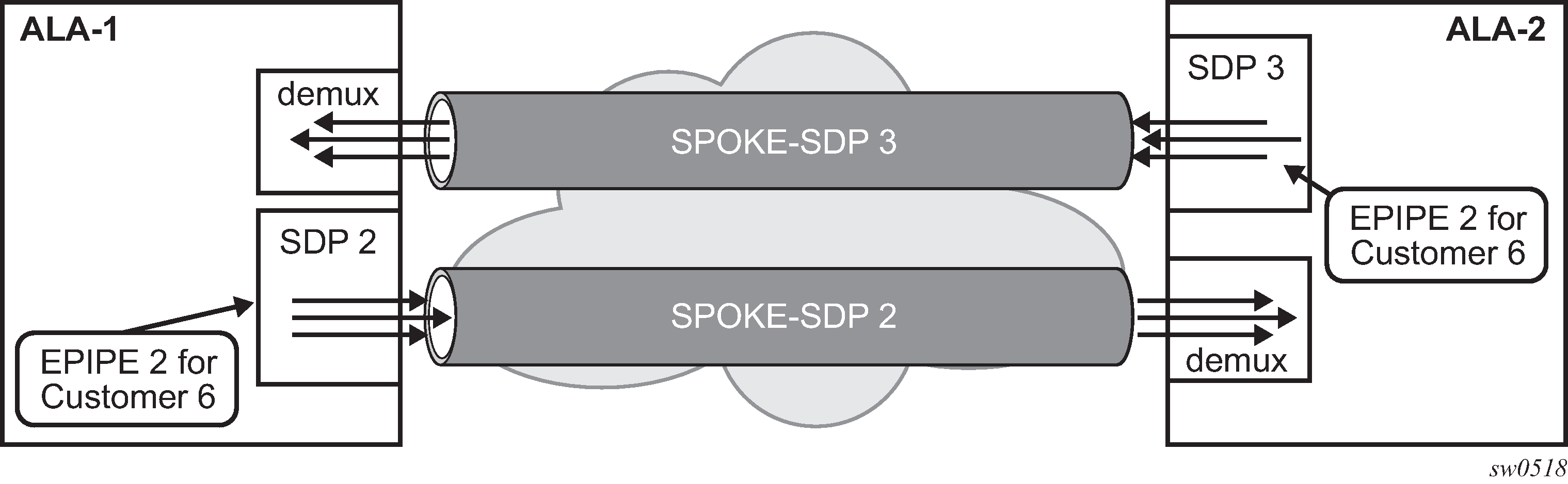
Use the following syntax to create a spoke-SDP binding with an Epipe service.
config>service# epipe service-id [customer customer-id]
    spoke-sdp sdp-id:vc-id [vc-type {ether | vlan}]
        vlan-vc-tag 0..4094
        egress
             filter {ip ip-filter-id}
             vc-label egress-vc-label
        ingress
             filter {ip ip-filter-id}
             vc-label ingress-vc-label
     no shutdown
The following shows the command usage to bind an Epipe service between ALA-1 and ALA-2. This example assumes that the SAPs have already been configured (see Distributed Epipe service).
A:ALA-1>config>service# epipe 5500
     config>service>epipe# spoke-sdp 2:123
     config>service>epipe>spoke-sdp# egress
     config>service>epipe>spoke-sdp>egress# vc-label 5500
     config>service>epipe>spoke-sdp>egress# exit
     config>service>epipe>spoke-sdp# ingress
     config>service>epipe>spoke-sdp>ingress# vc-label 6600
     config>service>epipe>spoke-sdp>ingress# exit
     config>service>epipe>spoke-sdp# no shutdown


ALA-2>config>service# epipe 5500
     config>service>epipe# spoke-sdp 2:456
     config>service>epipe>spoke-sdp# egress
     config>service>epipe>spoke-sdp>egress# vc-label 6600
     config>service>epipe>spoke-sdp>egress# exit
     config>service>epipe>spoke-sdp# ingress
     config>service>epipe>spoke-sdp>ingress# vc-label 5500
     config>service>epipe>spoke-sdp>ingress# exit
     config>service>epipe>spoke-sdp# no shutdown
The following is a sample SDP binding for the Epipe service between ALA-1 and ALA-2:
A:ALA-1>config>service# info
----------------------------------------------
...
     epipe 5500 customer 5 vpn 5500 create
          description ‟Distributed epipe service to east coast”
          sap 1/1/3:21 create
               ingress
                    qos 555
                    filter ip 1
               exit
          exit
          spoke-sdp 2:123 create
               ingress
                    vc-label 6600
               exit
               egress
                    vc-label 5500
               exit
          exit
          no shutdown
     exit
...
----------------------------------------------
A:ALA-1>config>service#


A:ALA-2>config>service# info
----------------------------------------------
...
exit
     epipe 5500 customer 5 vpn 5500 create
          description ‟Distributed epipe service to west coast”
          sap 441/1/4:550 create
               ingress
                    qos 654
               filter ip 1020
               exit
          exit
          spoke-sdp 2:456 create
               ingress
                    vc-label 5500
               exit
               egress
                    vc-label 6600
               exit
          exit
     no shutdown
     exit
...
----------------------------------------------
A:ALA-2>config>service#
Using spoke-SDP control words
The control word command provides the option to add a control word as part of the packet encapsulation for PW types for which the control word is optional. On the 7210 SAS an option is provided to enable it for Ethernet PW (Epipe). The control word might be needed because when ECMP is enabled on the network, packets of a specific PW may be spread over multiple ECMP paths if the hashing router mistakes the PW packet payload for an IPv4 or IPv6 packet. This occurs when the first nibble following the service label corresponds to a value of 4 or 6.
The control word negotiation procedures described in Section 6.2 of RFC 4447 are not supported, and therefore the service will only come up if the same C-bit value is signaled in both directions. If a spoke-SDP is configured to use the control word, but the node receives a label mapping message with a C-bit clear, the node releases the label with an ‟Illegal C-bit” status code per Section 6.1 of RFC 4447. As soon as the user enables control of the remote peer, the remote peer withdraws its original label and sends a label mapping with the C-bit set to 1 and the VLL service is up in both nodes.
When the control word is enabled, VCCV packets also include the VCCV control word. In that case, the VCCV CC type 1 (OAM CW) is signaled in the VCCV parameter in the FEC. If the control word is disabled on the spoke-SDP, the router alert label is used. In that case, VCCV CC type 2 is signaled. For a multi-segment PW (MS-PW), the CC type 1 is the only type supported, and therefore the control word must be enabled on the spoke-SDP to be able to use VCCV ping and VCCV-trace.
The following is a sample spoke-SDP control word configuration output:
-Dut-B>config>service>epipe# info
----------------------------------------------
description "Default epipe description for service id 2100"
sap 1/2/7:4 create
description "Default sap description for service id 2100"
exit
spoke-sdp 1:2001 create
control-word
exit
no shutdown
----------------------------------------------
*A:ALA-Dut-B>config>service>epipe#
Use the following syntax to disable the control word on spoke-sdp 1:2001.
*A:ALA-Dut-B>config>service>epipe# info
----------------------------------------------
description "Default epipe description for service id 2100"
sap 1/2/7:4 create
description "Default sap description for service id 2100"
exit
spoke-sdp 1:2001 create
exit
no shutdown
----------------------------------------------
*A:ALA-Dut-B>config>service>epipe
Configuring ingress and egress SAP parameters
By default, QoS policy ID 1 is applied to ingress service SAPs. Existing filter policies or other existing QoS policies can be associated with service SAPs on ingress and egress ports.
Ingress and egress SAP parameters can be applied to local and distributed Epipe service SAPs.
The following are sample SAP ingress and egress parameters:
ALA-1>config>service# epipe 5500
config>service>epipe# sap 1/1/3:21
config>service>epipe>sap# ingress
config>service>epipe>sap>ingress# qos 555
config>service>epipe>sap>ingress# filter ip 1
config>service>epipe>sap>ingress# exit
config>service>epipe>sap#
The following is a sample Epipe SAP ingress and egress configuration output:
A:ALA-1>config>service#
----------------------------------------------
...
        epipe 5500 customer 5 vpn 5500 create
            description "Distributed epipe service to east coast"
            sap 1/1/3:21 create
                ingress
                    qos 555
                    filter ip 1
                exit
            exit
            no shutdown
        exit
----------------------------------------------
A:ALA-1>config>service#
Configuring VLL resilience
The following figure displays an example to create VLL resilience. The zero revert-time value means that the VLL path will be switched back to the primary immediately after it comes back up.
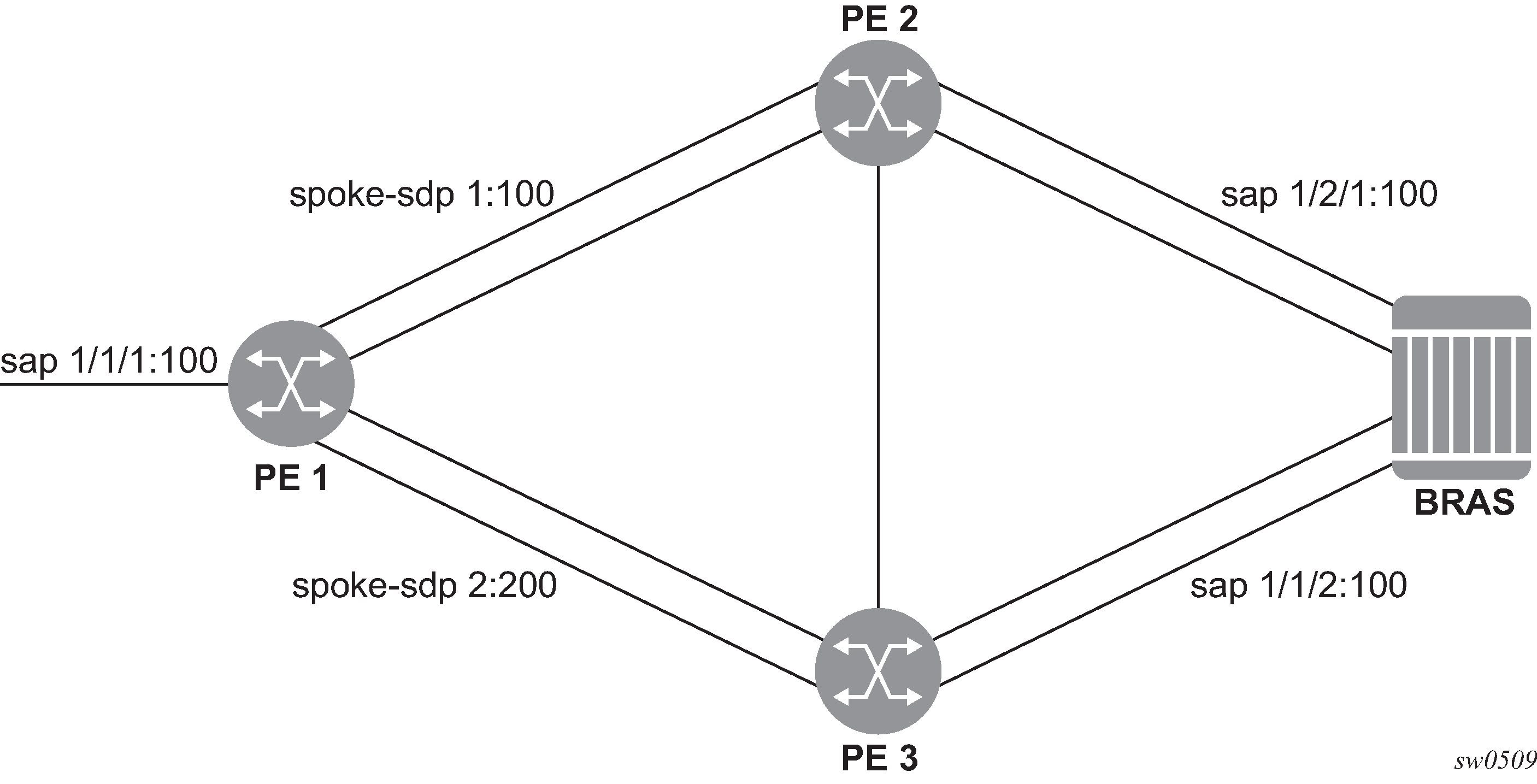
PE1
The following is a sample configuration output on PE1(a 7210 SAS-K 2F6C4T node):
*A:ALA-48>config>service>epipe# info
----------------------------------------------
endpoint "x" create
exit
endpoint "y" create
exit
spoke-sdp 1:100 endpoint "y" create
precedence primary
exit
spoke-sdp 2:200 endpoint "y" create
precedence 1
exit
no shutdown
----------------------------------------------
*A:ALA-48>config>service>epipe#
Configuring VLL resilience for a switched pseudowire path
The following figure shows an example of VLL resilience with pseudowire switching.
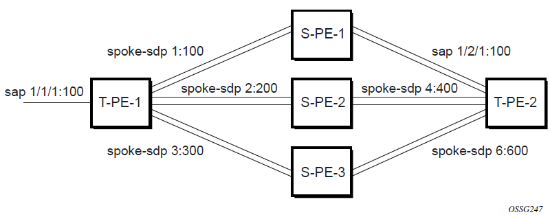
T-PE1
The following is a sample configuration output on TPE1 (which can be a 7210 SAS-K 2F6C4T or 7210 SAS-K 3SFP+ 8C):
*A:ALA-48>config>service>epipe# info
----------------------------------------------
endpoint "x" create
exit
endpoint "y" create
exit
sap 1/1/1:100 endpoint "x" create
exit
spoke-sdp 1:100 endpoint "y" create
precedence primary
exit
spoke-sdp 2:200 endpoint "y" create
precedence 1
exit
spoke-sdp 3:300 endpoint "y" create
precedence 1
exit
no shutdown
----------------------------------------------
*A:ALA-48>config>service>epipe#
T-PE2
The following is a sample configuration output on TPE2:
*A:ALA-49>config>service>epipe# info
----------------------------------------------
endpoint "x" create
exit
endpoint "y" create
revert-time 100
exit
spoke-sdp 4:400 endpoint "y" create
precedence primary
exit
spoke-sdp 5:500 endpoint "y" create
precedence 1
exit
spoke-sdp 6:600 endpoint "y" create
precedence 1
exit
no shutdown
----------------------------------------------
*A:ALA-49>config>service>epipe#
S-PE1
The following is a sample configuration output on S-PE1:
*A:ALA-50>config>service>epipe# info
----------------------------------------------
...
spoke-sdp 1:100 create
exit
spoke-sdp 4:400 create
exit
no shutdown
----------------------------------------------
*A:ALA-49>config>service>epipe#
Configuring default QinQ SAPs for Epipe transit traffic in a ring scenario in access-uplink mode

In the preceding figure, 7210-1 is used to deliver some services to customers connected to the device, and additionally it needs to pass through transit from other nodes on the ring (example – traffic from 7210-2 to 7210-3 OR from 7210-2 to 7750 –SR onto the core network).
Without default QinQ SAPs, the user would need to configure a service on 7210-1, with access-uplink SAPs for each service originating on some other node in the ring. With support for default QinQ SAPs, all traffic that does not need to be delivered to any customer service configured on 7210-1 can be switched using the Epipe service. The following are the sample configuration commands in this scenario:
ALA-1>config>service# epipe 8 customer 1 svc-sap-type null-star create
            sap 1/1/5:*.* create
                statistics
                    ingress
                    exit
                exit
            exit
            sap 1/1/6:*.* create
                statistics
                    ingress
                    exit
                exit
            exit
            no shutdown
        exit
Service management tasks
This section describes the Epipe service management tasks.
Modifying Epipe service parameters
The following shows the command usage to add an accounting policy to an existing SAP:
- Example:
config>service# epipe 2
    config>service>epipe# sap 1/1/3:21
    config>service>epipe>sap# accounting-policy 14
    config>service>epipe>sap# exit
The following is a sample SAP configuration output:
ALA-1>config>service# info
----------------------------------------------
epipe 2 customer 6 vpn 2 create
            description "Distributed Epipe service to east coast"
            sap 1/1/3:21 create
accounting-policy 14
            exit
            no shutdown
        exit
----------------------------------------------
ALA-1>config>service#
Disabling an Epipe service
Use the following syntax to shut down an Epipe service without deleting the service parameters.
config>service> epipe service-id
    shutdown
- Example:
config>service# epipe 2
    config>service>epipe# shutdown
    config>service>epipe# exit
Re-enabling an Epipe service
Use the following syntax to re-enable an Epipe service that was shut down.
config>service# epipe service-id
    no shutdown
- Example:
config>service# epipe 2
    config>service>epipe# no shutdown
    config>service>epipe# exit
Deleting an Epipe service
Perform the following steps before deleting an Epipe service.
Shut down the SAP.
Delete the SAP.
Shut down the service.
Use the following syntax to delete an Epipe service.
config>service
    [no] epipe service-id
    shutdown
    [no] sap sap-id
shutdown- Example:
config>service# epipe 2
    config>service>epipe# sap 1/1/3:21
    config>service>epipe>sap#
    config>service>epipe>sap# exit
    config>service>epipe# no sap 1/1/3:21
    config>service>epipe# epipe 2
    config>service>epipe# shutdown
    config>service>epipe# exit
    config>service# no epipe 2
VLL services command reference
Command hierarchy
Epipe service configuration commands
Epipe global commands for 7210 SAS-D
config
    - service
        - epipe service-id [customer customer-id] [create] [svc-sap-type {null-star | dot1q-preserve | any | dot1q-range}] [customer-vid vlan-id]
        - no epipe service-id
            - description description-string
            - no description
            - [no] endpoint endpoint-name [create]
            - sap sap-id [create]
            - no sap sap-id
            - service-name service-name
            - no service-name
            - [no] shutdown
Epipe global commands for 7210 SAS-Dxp
config
    - service
        - epipe service-id [customer customer-id] [create] [vpn vpn-id] [svc-sap-type {null-star | dot1q | dot1q-preserve | any | dot1q-range | qinq-inner-tag-preserve}] [customer-vid vlan-id] [uplink-type {l2 | mpls}]
        - no epipe service-id
            - description description-string
            - no description
            - sap sap-id [create]
            - no sap sap-id
            - service-name service-name
            - no service-name
            - [no] shutdown
Epipe global commands for 7210 SAS-K 2F1C2T
config
    - service
        - epipe service-id [customer customer-id] [create]
        - epipe service-id [customer customer-id] [create] [svc-sap-type {any | dot1q-range}]
        - epipe service-id [customer customer-id] [create] [svc-sap-type {any | dot1q-range}]
        - no epipe service-id
            - description description-string
            - no description
            - sap sap-id [create]
            - no sap sap-id
            - service-mtu octets
            - no service-mtu
            - service-name service-name
            - no service-name
            - [no] shutdown
Epipe global commands for 7210 SAS-K 2F6C4T and 7210 SAS-K 3SFP+ 8C
config
    - service
        - epipe service-id [customer customer-id] [create]
        - epipe service-id [customer customer-id] [create] [svc-sap-type {any | dot1q-range}]
        - epipe service-id [customer customer-id] [create] [svc-sap-type {any | dot1q-range}]
        - no epipe service-id
            - description description-string
            - no description
            - [no] endpoint endpoint-name [create]
                - active-hold-delay active-endpoint-delay
                - no active-hold-delay
                - revert-time [revert-time | infinite]
                - no revert-time
                - standby-signaling-master
                - [no] standby-signaling-master
            - sap sap-id [create]
            - no sap sap-id
            - service-mtu octets
            - no service-mtu
            - service-name service-name
            - no service-name
            - [no] shutdown
            - [no] spoke-sdp
Epipe SAP configuration commands
config
    - service
        - epipe service-id
        - no epipe service-id
            - no sap sap-id
                - accounting-policy acct-policy-id
                - no accounting-policy acct-policy-id
                - [no] collect-stats
                - description description-string
                - no description
                - eth-cfm
                    - [no] mep mep-id domain md-index association ma-index [direction {up | down}] primary-vlan-enable
                        - [no] ais-enable
                            - [no] client-meg-level [[level [level ...]]
                            - [no] interval {1 | 60}
                            - [no] priority priority-value
                            - no send-ais-on-port-down
                            - send-ais-on-port-down
                        - [no] ccm-enable
                        - [no] ccm-ltm-priority priority
                        - defect-oper-group name
                        - no defect-oper-group
                        - [no] description
                        - [no] eth-test-enable
                            - [no] bit-error-threshold bit-errors
                            - [no] test-pattern {all-zeros | all-ones} [crc-enable]
                        - [no] fault-propagation-enable {use-if-tlv | suspendccm}
                        - low-priority-defect {allDef | macRemErrXcon | remErrXcon | errXcon | xcon | noXcon}
                        - [no] mac-address mac-address
                        - [no] one-way-delay-threshold seconds
                        - [no] shutdown
                    - [no] squelch-ingress-levels [md-level [md-level]]
                - mac-swap-enable
                - no mac-swap-enable
                - ethernet
                    - [no] ais-enable
                - [no] ignore-oper-down
                - [no] shutdown
Epipe SAP meter override commands
config
    - service
        - epipe service-id
        - no epipe service-id
            - no sap sap-id
                - ingress
                    - meter-override
                        - meter meter-id [create]
                        - no meter meter-id
                            - adaptation-rule [pir adaptation-rule] [cir adaptation-rule]
                            - cbs size [kbits | bytes | kbytes]
                            - no cbs
                            - mbs size [kbits | bytes | kbytes]
                            - no mbs
                            - mode mode
                            - no mode
                            - rate cir cir-rate [pir pir-rate]
                            - no rate
Epipe SAP statistics commands for 7210 SAS-D
config
    - service
        - epipe service-id
        - no epipe service-id
            - no sap sap-id
                - statistics
                    - egress
                        - [no] forwarded-count
                    - ingress
                        - counter-mode {in-out-profile-count | forward-drop-count}
                        - [no] received-count
Epipe SAP statistics commands for 7210 SAS-Dxp
config
    - service
        - epipe service-id
        - no epipe service-id
            - no sap sap-id
                - statistics
                    - ingress
                        - counter-mode {in-out-profile-count | forward-drop-count}
Epipe spoke-SDP configuration commands for 7210 SAS-K 2F6C4T and 7210 SAS-K 3SFP+ 8C
config
    - service]
        - epipe service-id
        - no epipe service-id
            - spoke-sdp sdp-id[:vc-id] [vc-type {ether | vlan}] [create] [no-endpoint]
            - spoke-sdp sdp-id[:vc-id] [vc-type {ether | vlan}] [create] endpoint
            - no spoke-sdp sdp-id[:vc-id]
                - accounting-policy acct-policy-id
                - no accounting-policy
                - adv-service-mtu octets
                - no adv-service-mtu
                - [no] collect-stats
                - [no] control-word
                - [no] description
                - [no] egress
                    - [no] vc-label egress-vc-label
                - eth-cfm
                    - [no] ais-enable
                    - [no] mep mep-id domain md-index association ma-index [direction {up | down}]
                        - [no] ais-enable
                            - [no] client-meg-level [[level [level ...]]
                            - [no] interval {1 | 60}
                            - [no] priority priority-value
                        - [no] ccm-enable
                        - [no] ccm-ltm-priority priority
                        - [no] description
                        - [no] eth-test-enable
                            - [no] bit-error-threshold bit-errors
                            - [no] test-pattern {all-zeros | all-ones} [crc-enable]
                        - [no] fault-propagation-enable {use-if-tlv | suspendccm}
                        - low-priority-defect {allDef | macRemErrXcon | remErrXcon | errXcon | xcon | noXcon}
                        - [no] mac-address mac-address
                        - [no] one-way-delay-threshold seconds
                        - [no] shutdown
                    - mip [mac mac address]
                    - mip default-mac
                    - no mip
                - [no] force-vlan-vc-forwarding
                - hash-label [signal-capability]
                - no hash-label
                - [no] ingress
                    - [no] vc-label egress-vc-label
                - precedence [precedence-value| primary]
                - no precedence
                - no pw-status-signaling
                - pw-status-signaling
                - [no] shutdown
                - suppress-vc-vlan
                - no suppress-vc-vlan
                - vlan-vc-tag 0..4094
                - no vlan-vc-tag [0..4094]
Epipe SAP configuration — QoS and filter commands for 7210 SAS-D and 7210 SAS-Dxp
config
    - service
        - epipe service-id [customer customer-id] [create] [svc-sap-type {null-star | dot1q-preserve | any | dot1q-range}] [customer-vid vlan-id]
        - epipe service-id [customer customer-id] [create] [svc-sap-type {null-star | dot1q-preserve | dot1q}] [customer-vid vlan-id]
        - no epipe service-id
            - no sap sap-id [create]
                - egress
                    - aggregate-meter-rate rate-in-kbps [burst burst-in-kbits] [enable-stats]
                    - no aggregate-meter-rate
                    - filter [ip ip-filter-id]
                    - filter [ipv6 ipv6 -filter-id]
                    - filter [mac mac-filter-id]
                    - no filter [ip ip-filter-id] [ipv6 ipv6 -filter-id] [mac mac-filter-id]
                - ingress
                    - aggregate-meter-rate rate-in-kbps [burst burst-in-kbits]
                    - no aggregate-meter-rate
                    - filter [ip ip-filter-id]
                    - filter [ipv6 ipv6-filter-id]
                    - filter [mac mac-filter-id]
                    - no filter [ip ip-filter-id] [ ipv6 ipv6-filter-id] [mac mac-filter-id]
                    - qos policy-id
                    - no qos
Epipe SAP configuration — QoS and filter commands for 7210 SAS-K 2F1C2T, 7210 SAS-K 2F6C4T, and 7210 SAS-K 3SFP+ 8C
config
    - service
        - epipe service-id [customer customer-id] [create] [svc-sap-type {any | dot1q-range}]
        - no epipe service-id
            - no sap sap-id [create]
                - egress
                    - agg-shaper-rate agg-rate
                    - no agg-shaper-rate
                    - dot1p-inner dot1p-inner
                    -  no dot1p-inner
                    -  no dot1p-outer
                    -  dot1p-outer dot1p-outer
                    - filter [ip ip-filter-id]
                    - filter [ipv6 ipv6 -filter-id]
                    - filter [mac mac-filter-id] (app
                    - no filter [ip ip-filter-id] [ipv6 ipv6 -filter-id] [mac mac-filter-id]
                    - qos policy-id
                    - no qos
                - ingress
                    - agg-shaper-rate agg-rate
                    - no agg-shaper-rate
                    - aggregate-meter-rate rate-in-kbps [burst burst-in-kbits]
                    - no aggregate-meter-rate
                    - filter [ip ip-filter-id]
                    - filter [ ipv6 ipv6-filter-id]
                    - filter [mac mac-filter-id]
                    - no filter [ip ip-filter-id] [ipv6 ipv6-filter-id] [mac mac-filter-id]
                    - qos policy-id
                    - no qos
Connection profile commands
config
    - connection-profile conn-prof-id [create]
    - no connection-profile conn-prof-id
        - description description-string
        - no description
        - ethernet
            - no ranges
        - ranges vlan ranges [vlan ranges...(up to 32 max)]
Show commands
show
    - service
        - id service-id
            - all
            - base
            - sap
            - stp [sap-id] [detail]]
        - sap-using [sap sap-id]
        - sap-using [ingress | egress] filter filter-id
        - sap-using [ingress ] qos-policy qos-policy-id
        - service-using [epipe] [vpls] [mirror] [i-vpls] [m-vpls] [sdp sdp-id] [customer customer-id]
show
    - connection-profile [conn-prof-id] [associations]
Clear commands
clear
    - service
        - id service-id
        - statistics
            - id service-id
            - counters
            - sap sap-id {all | counters | stp | l2pt}
Command descriptions
VLL service configuration commands
Generic commands
shutdown
Syntax
[no] shutdown
Context
config>service>epipe
config>service>epipe>sap
config>service>epipe>sap>eth-cfm>mep
Platforms
Supported on all 7210 SAS platforms as described in this document
Description
This command administratively disables an entity. When disabled, an entity does not change, reset, or remove any configuration settings or statistics.
The operational state of the entity is disabled as well as the operational state of any entities contained within. Many objects must be shut down before they may be deleted.
Services are created in the administratively down (shutdown) state. When a no shutdown command is entered, the service becomes administratively up, then tries to enter the operationally up state.
The no form of this command places the entity into an administratively enabled state.
description
Syntax
description description-string
no description
Context
config>service>epipe
config>service>epipe>sap
config>service>epipe>spoke-sdp
config>connection-profile
Platforms
Supported on all 7210 SAS platforms as described in this document
Description
This command creates a text description stored in the configuration file for a configuration context. The description command associates a text string with a configuration context to help identify the content in the configuration file.
The no form of this command removes the string from the configuration.
Parameters
- description-string
Specifies the description character string. Allowed values are any string up to 80 characters composed of printable, 7-bit ASCII characters. If the string contains special characters (#, $, spaces, and so on), the entire string must be enclosed within double quotes.
eth-cfm
Syntax
eth-cfm
Context
config>service>epipe>sap
Platforms
Supported on all 7210 SAS platforms as described in this document
Description
Commands in this context configure ETH-CFM parameters.
mep
Syntax
mep mep-id domain md-index association ma-index [direction {up | down}] primary-vlan-enable
no mep mep-id domain md-index association ma-index
Context
config>service>epipe>sap>eth-cfm
Platforms
Supported on all 7210 SAS platforms as described in this document
Description
This command provisions the maintenance endpoint (MEP).
The no form of this command reverts to the default values.
For more information about ETH-CFM support for different services, see the 7210 SAS-D, Dxp, K 2F1C2T, K 2F6C4T, K 3SFP+ 8C OAM and Diagnostics Guide.
Parameters
- mep-id
Specifies the maintenance association endpoint identifier.
- md-index
Specifies the maintenance domain (MD) index value.
- ma-index
Specifies the MA index value.
- direction {up | down}
Specifies the direction in which the maintenance association (MEP) faces on the bridge port.
up — Sends ETH-CFM messages toward the MAC relay entity.
down — Sends ETH-CFM messages away from the MAC relay entity.
- primary-vlan-enable
Keyword that provides a method for linking with the primary VLAN configured under the bridge-identifier for the MA. This must be configured as part of the creation step and can only be changed by deleting the MEP and recreating it. Primary VLANs are only supported under Ethernet SAPs. This parameter is only supported on the 7210 SAS-Dxp, 7210 SAS-K 2F1C2T, 7210 SAS-K 2F6C4T, and 7210 SAS-K 3SFP+ 8C.
VLL global commands
epipe
Syntax
epipe service-id [customer customer-id] [create] [svc-sap-type {null-star|dot1q|dot1q-preserve}] [customer-vid vlan-id]
epipe service-id [customer customer-id] [create] [svc-sap-type {null-star|dot1q-preserve|any|dot1q-range}] [customer-vid vlan-id]
epipe service-id [customer customer-id] [create] [svc-sap-type {any|dot1q-range}]
epipe service-id [customer customer-id] [create] [svc-sap-type {null-star|dot1q|dot1q-preserve|any|dot1q-range|qinq-inner-tag-preserve}]
epipe [customer customer-id] [create] [vpn vpn-id] [svc-sap-type {null-star | dot1q | dot1q-preserve | any | dot1q-range | qinq-inner-tag-preserve}] [customer-vid vlan-id] [uplink-type {l2 | mpls}]
no epipe service-id
Context
config>service
Platforms
Supported on all 7210 SAS platforms as described in this document
Description
This command configures an Epipe service instance. This command is used to configure a point-to-point Epipe service. An Epipe connects two endpoints, defined as Service Access Points (SAPs). In a local service, the SAPs may be defined in one 7210 SAS node and in distributed service the SAPs may be defined on two different 7210 SAS nodes.
7210 SAS-D, 7210 SAS-Dxp, and 7210 SAS-K 2F1C2T platforms only support local SAP to SAP service.
7210 SAS-K 2F6C4T and 7210 SAS-K 3SFP+ 8C platforms support both local and distributed service.
No MAC learning or filtering is provided on an Epipe.
When a service is created, the customer keyword and customer-id must be specified and associate the service with a customer. The customer-id must already exist, having been created using the customer command in the service context. When a service has been created with a customer association, it is not possible to edit the customer association. The service must be deleted and recreated with a new customer association.
When a service is created, the use of the customer customer-id is optional for navigating into the service configuration context. Attempting to edit a service with the incorrect customer-id specified results in an error.
By default, no Epipe services exist until they are explicitly created with this command.
The tables in the following links list the allowed SAPs for a particular value of svc-sap-type on different 7210 platforms:
SAP and service combinations for 7210 SAS-D and 7210 SAS-Dxp
SAP and service combinations for 7210 SAS-K 2F1C2T, 7210 SAS-K 2F6C4T, and 7210 SAS-K 3SFP+ 8C
The no form of this command deletes the Epipe service instance with the specified service-id. The service cannot be deleted until the service has been shut down.
Parameters
- service-id
Specifies the unique service identification number or string identifying the service in the service domain. This ID must be unique to this service and may not be used for any other service of any type. The service-id must be the same number used for every 7210 SAS on which this service is defined.
service-id-epipe
- customer customer-id
Specifies the customer ID number to be associated with the service. This parameter is required on service creation and optional for service editing or deletion.
epipe customer
- svc-sap-type
Keyword that specifies the type of access SAPs and access-uplink SAPs allowed in the service.
vpn
- customer-vid vlan-id
Defines the dot1q VLAN ID to be specified while creating the local dot1q SAP for svc-sap-type dot1q-preserve. Applicable only for Access-uplink mode.
- create
Keyword used to create the service instance. The create keyword requirement can be enabled or disabled in the environment>create context.
endpoint
Syntax
[no] endpoint endpoint-name
Context
config>service>epipe
Platforms
7210 SAS-K 2F6C4T and 7210 SAS-K 3SFP+ 8C
Description
This command configures a service endpoint.
Parameters
- endpoint-name
Specifies an endpoint name.
active-hold-delay
Syntax
active-hold-delay active-hold-delay
no active-hold-delay
Context
config>service>epipe>endpoint
Platforms
7210 SAS-K 2F6C4T and 7210 SAS-K 3SFP+ 8C
Description
This command specifies that the node will delay sending the change in the T-LDP status bits for the VLL endpoint when the MC-LAG transitions the LAG subgroup that hosts the SAP for this VLL endpoint from active to standby or when any object in the endpoint. For example, SAP, ICB, or regular spoke-SDP, transitions from up to down operational state.
A value of zero (default) means that when the MC-LAG transitions the LAG subgroup that hosts the SAP for this VLL endpoint from active to standby, the node immediately sends new T-LDP status bits indicating the new value of standby over the spoke-SDPs that are on the mate-endpoint of the VLL. The same applies when any object in the endpoint changes an operational state from up to down.
There is no delay applied to the VLL endpoint status bit advertisement when the MC-LAG transitions the LAG subgroup that hosts the SAP from "standby" to "active", or when any object in the endpoint transitions to an operationally up state.
Default
0
Parameters
- active-hold-delay
Specifies the active hold delay in 100s of milliseconds.
revert-time
Syntax
revert-time [revert-time | infinite]
no revert-time
Context
config>service>epipe>endpoint
Platforms
7210 SAS-K 2F6C4T and 7210 SAS-K 3SFP+ 8C
Description
This command configures the time to wait before reverting back to the primary spoke-SDP defined on this service endpoint, after having failed over to a backup spoke-SDP.
Parameters
- revert-time
Specify the time, in seconds, to wait before reverting to the primary SDP.
- infinite
Keyword that causes the endpoint to be non-revertive.
standby-signaling-master
Syntax
[no] standby-signaling-master
Context
config>service>epipe>endpoint
Platforms
7210 SAS-K 2F6C4T and 7210 SAS-K 3SFP+ 8C
Description
When this command is enabled, the pseudowire standby bit (value 0x00000020) is sent to T-LDP peer for each spoke-SDP of the endpoint that is selected as a standby.
Default
no standby-signaling-master
service-mtu
Syntax
service-mtu octets
no service-mtu
Context
config>service>epipe
Platforms
7210 SAS-K 2F1C2T, 7210 SAS-K 2F6C4T, 7210 SAS-K 3SFP+ 8C
Description
This command configures the service payload Maximum Transmission Unit (MTU), in bytes, for the service. This MTU value overrides the service-type default MTU. The service-mtu defines the payload capabilities of the service. It is used by the system to validate the SAP and SDP binding operational state within the service.
The service MTU and a SAP service delineation encapsulation overhead (that is, 4 bytes for a dot1q tag) is used to derive the required MTU of the physical port or channel on which the SAP was created. If the required payload is larger than the port or channel MTU, the SAP is placed in an inoperative state. If the required MTU is equal to or less than the port or channel MTU, the SAP is able to transition to the operative state.
In the event that a service MTU, port or channel MTU, or path MTU is dynamically or administratively modified, all associated SAP and SDP binding operational states are automatically reevaluated.
The no form of this command reverts to the default service-mtu value for the indicated service type.
Default
epipe: 1514
The following table displays MTU values for specific VC types.
VC-type |
Example service MTU |
Advertised MTU |
|---|---|---|
Ethernet |
1514 |
1500 |
Ethernet (with preserved Dot1q) |
1518 |
1504 |
VPLS |
1514 |
1500 |
VPLS (with preserved Dot1q) |
1518 |
1504 |
VLAN (Dot1p transparent to MTU value) |
1514 |
1500 |
VLAN (QinQ with preserved bottom Qtag) |
1518 |
1504 |
Parameters
- octets
Specifies the size of the MTU in octets, expressed as a decimal integer.
service-name
Syntax
service-name service-name
no service-name
Context
config>service>epipe
Platforms
Supported on all 7210 SAS platforms as described in this document
Description
This command configures an optional service name that adds a name identifier to a specific service to then use that service name in configuration references as well as display and use service names in show commands throughout the system. This helps the service provider or administrator to identify and manage services.
All services are required to assign a service ID to initially create a service. However, either the service ID or the service name can be used to identify and reference a specific service when it is initially created.
Parameters
- service-name
Specifies a unique service name, up to 64 characters, to identify the service. Service names may not begin with an integer (0-9).
VLL SAP commands
sap
Syntax
sap sap-id [create]
no sap sap-id
Context
config>service>epipe
Platforms
Supported on all 7210 SAS platforms as described in this document
Description
This command creates a Service Access Point (SAP) within a service. A SAP is a combination of port and encapsulation parameters that identify the service access point on the interface and within the 7210 device. Each SAP must be unique.
All SAPs must be explicitly created. If no SAPs are created within a service or on an IP interface, a SAP does not exist on that object.
Enter an existing SAP without the create keyword to edit SAP parameters. The SAP is owned by the service in which it was created.
On the 7210 SAS-D and 7210 SAS-Dxp, in a single physical port only one SAP can belong to one service. Multiple SAPs can be defined over a physical port but each of these SAPs should belong to different services. This restriction does not apply to the 7210 SAS-K 2F1C2T, 7210 SAS-K 2F6C4T, or 7210 SAS-K 3SFP+ 8C.
A SAP can be associated with only a single service. A SAP can only be defined on a port that has been configured as an access port. Additionally, in access-uplink mode, SAPs can also be defined on an access-uplink port. Access-uplink SAPs are network-facing SAPs representing dot1q or QinQ tunnels used to transport traffic toward the service nodes.
If a port is shut down, all SAPs on that port become operationally down. When a service is shut down, SAPs for the service are not displayed as operationally down, although all traffic traversing the service is discarded.
The operational state of a SAP is relative to the operational state of the port on which the SAP is defined.
The following encapsulations are supported.
Ethernet access SAPs support null, dot1q, and QinQ.
Ethernet access-uplink SAPs support only QinQ encapsulation.
The no form of this command deletes the SAP with the specified port. When a SAP is deleted, all configuration parameters for the SAP are also be deleted. For IES, the IP interface must be shut down before the SAP on that interface may be removed.
Special Cases
- Default SAPs
A default SAP has the following format: port-id:*. This type of SAP is supported only on Ethernet MDAs, and its creation is only allowed in the scope of Layer 2 services (Epipe and VPLS).
Parameters
- sap-id
Specifies the physical port identifier portion of the SAP. See Common CLI command descriptions for command syntax.
- create
Keyword used to create a SAP instance. The create keyword requirement can be enabled or disabled in the environment>create context.
accounting-policy
Syntax
accounting-policy acct-policy-id
no accounting-policy [acct-policy-id]
Context
config>service>epipe>sap
Platforms
Supported on all 7210 SAS platforms as described in this document
Description
This command enables the accounting policy context that can be applied to a SAP.
An accounting policy must be defined before it can be associated with a SAP. If the policy-id does not exist, an error message is generated.
A maximum of one accounting policy can be associated with a SAP at one time. Accounting policies are configured in the config>log context.
The no form of this command removes the accounting policy association from the SAP, and the accounting policy reverts to the default.
Default
Default accounting policy.
Parameters
- acct-policy-id
Specifies the accounting policy-id, as configured in the config>log> accounting-policy context.
collect-stats
Syntax
[no] collect-stats
Context
config>service>epipe>sap
Platforms
Supported on all 7210 SAS platforms as described in this document
Description
This command enables accounting and statistical data collection for the SAP, network port, or IP interface. When applying accounting policies, by default the data is collected in the appropriate records and written to the designated billing file.
When the no collect-stats command is issued, the statistics are still accumulated by the cards. However, the CPU will not obtain the results and write them to the billing file. If a subsequent collect-stats command is issued, the counters written to the billing file include all the traffic while the no collect-stats command was in effect.
Default
no collect-stats
ethernet
Syntax
ethernet
Context
config>service>epipe>sap
Platforms
Supported on all 7210 SAS platforms as described in this document
Description
This command configures Ethernet properties in this SAP.
ais-enable
Syntax
[no] ais-enable
Context
config>service>epipe>sap>eth-cfm
Platforms
Supported on all 7210 SAS platforms as described in this document
Description
This command enables the generation and the reception of AIS messages.
client-meg-level
Syntax
client-meg-level [[level [level ...]]
no client-meg-level
Context
config>service>epipe>sap>eth-cfm>ais-enable
Platforms
Supported on all 7210 SAS platforms as described in this document
Description
This command configures the client maintenance entity group (MEG) levels to use for AIS message generation. Up to 7 levels can be provisioned, with the restriction that the client MEG level must be higher than the local MEG level.
Parameters
- level
Specifies the client MEG level.
interval
Syntax
interval {1 | 60}
no interval
Context
config>service>epipe>sap>eth-cfm>ais-enable
Platforms
Supported on all 7210 SAS platforms as described in this document
Description
This command specifies the transmission interval of AIS messages.
Parameters
- 1 | 60
Specifies the transmission interval of AIS messages, in seconds.
priority
Syntax
priority priority-value
no priority
Context
config>service>epipe>sap>eth-cfm>ais-enable
Platforms
Supported on all 7210 SAS platforms as described in this document
Description
This command specifies the priority of AIS messages originated by the node.
Parameters
- priority-value
Specifies the priority value of the AIS messages originated by the node.
ccm-enable
Syntax
[no] ccm-enable
Context
config>service>epipe>sap>eth-cfm>mep
Platforms
Supported on all 7210 SAS platforms as described in this document
Description
This command enables the generation of CCM messages.
The no form of this command disables the generation of CCM messages.
ccm-ltm-priority
Syntax
ccm-ltm-priority priority
no ccm-ltm-priority
Context
config>service>epipe>sap>eth-cfm>mep
Platforms
Supported on all 7210 SAS platforms as described in this document
Description
This command specifies the priority value for CCMs and LTMs transmitted by the MEP.
The no form of this command removes the priority value from the configuration.
Default
The highest priority on the bridge-port.
Parameters
- priority
Specifies the priority of CCM and LTM messages.
defect-oper-group
Syntax
defect-oper-group name
no defect-oper-group
Context
config>service>epipe>sap>eth-cfm>mep
Platforms
Supported on all 7210 SAS platforms as described in this document, except 7210 SAS-D
Description
This command configures an operational group for fault propagation.
See the 7210 SAS-D, Dxp, K 2F1C2T, K 2F6C4T, K 3SFP+ 8C OAM and Diagnostics Guide for more information about fault propagation in an Epipe service.
The no form of this command removes the operational group.
Parameters
- name
Specifies the operational group name, up to 32 characters.
llf
Syntax
[no] llf
Context
config>service>epipe>sap>ethernet
Platforms
Supported on all 7210 SAS platforms as described in this document
Description
This command enables Link Loss Forwarding (LLF) on an Ethernet port or an ATM port. This command provides an end-to-end OAM fault notification for Ethernet VLL service. It brings down the Ethernet port (Ethernet LLF) toward the attached CE when there is a local fault on the Pseudowire or service, or a remote fault on the SAP or pseudowire, signaled with label withdrawal or T-LDP status bits. It ceases when the fault disappears.
The Ethernet port must be configured for null encapsulation.
ignore-oper-down
Syntax
[no] ignore-oper-down
Context
config>service>epipe>sap
Platforms
7210 SAS-D, 7210 SAS-Dxp, 7210 SAS-K 2F1C2T, 7210 SAS-K 2F6C4T, 7210 SAS-K 3SFP+ 8C
Description
This command configures the optional command for a specific SAP to ignore the transition of the operational state to down when a SAP fails. Only a single SAP in an Epipe may use this option.
Default
no ignore-oper-down
send-ais-on-port-down
Syntax
[no] send-ais-on-port-down
Context
config>service>epipe>sap>eth-cfm>mep>ais-enable
config>service>vpls>sap>eth-cfm>mep>ais-enable
Platforms
Supported on all 7210 SAS platforms as described in this document
Description
This command specifies that ETH-AIS should be generated for client MEPs immediately when port down event is detected on the port where the server MEP (and the associated SAP) resides. By default, the system generates an ETH-AIS message, if enabled, when CCM messages are not received within the configured time period. On a subsequent port up event, the AIS messages continue to be sent until valid CCMs are received. If there are no remote MEPs configured for the MEP, on a subsequent port up event, the AIS messages are not sent.
The no form of this command reverts to the default value.
Default
no send-ais-on-port-down
eth-test-enable
Syntax
[no] eth-test-enable
Context
config>service>epipe>sap>eth-cfm>mep
Platforms
Supported on all 7210 SAS platforms as described in this document
Description
This command enables the Ethernet test functionality on MEP. For ETH-test to work, users must configure ETH-test parameters on both sender and receiver nodes. The ETH-test can then be performed using the following OAM commands:
oam eth-cfm eth-test mac-address mep mep-id domain md-index association ma-index [priority priority] [data-length data-length]
A check is performed for both the provisioning and test to ensure that the MEP is an Y.1731 MEP (MEP provisioned with domain format none, association format icc-based.) If not, the operation fails. An error message in the CLI and SNMP indicates the problem.
test-pattern
Syntax
test-pattern {all-zeros | all-ones} [crc-enable]
no test-pattern
Context
config>service>epipe>sap>eth-cfm>mep>eth-test-enable
Platforms
Supported on all 7210 SAS platforms as described in this document
Description
This command configures the test pattern for eth-test frames.
The no form of this command removes the values from the configuration.
Parameters
- all-zeros
Keyword that specifies to use all zeros in the test pattern.
- all-ones
Keyword that specifies to use all ones in the test pattern.
- crc-enable
Keyword that generates a CRC checksum.
bit-error-threshold
Syntax
bit-error-threshold errors
no bit-error-threshold
Context
config>service>epipe>sap>eth-cfm>mep>eth-test-enable
Platforms
Supported on all 7210 SAS platforms as described in this document
Description
This command is used to specify the threshold value of bit errors.
one-way-delay-threshold
Syntax
one-way-delay-threshold seconds
Context
config>service>epipe>sap>eth-cfm>mep
Platforms
Supported on all 7210 SAS platforms as described in this document
Description
This command enables eth-test functionality on MEP.
Parameters
- seconds
Specifies the one-way delay threshold in seconds.
squelch-ingress-levels
Syntax
squelch-ingress-levels [md-level [md-level]]
no squelch-ingress-levels
Context
config>service>epipe>sap>eth-cfm
Platforms
7210 SAS-Dxp
Description
This command configures the levels of the ETH-CFM packets that are silently discarded on ingress into the SAP from the wire that matches the service delineation of the SAP.
All ETH-CFM packets inbound to the SAP that match the configured levels are dropped without regard for any other ETH-CFM criteria. No statistical information or drop count is available for any ETH-CFM packet that is silently discarded by this option.
The user must configure a complete contiguous list of MD-levels up to the highest level that are to be dropped. The command must be retyped in complete form to modify a previous configuration if the user does not want to delete it first.
Entering the command with no associated MD-level information is equivalent to the no form of this command.
The no form of this command removes the silent discarding of previously matching ETH-CFM PDUs.
Default
no squelch-ingress-levels
Parameters
- md-level
-
Identifies the level
mac-swap-enable
Syntax
[no] mac-swap-enable
Context
config>service>epipe>sap config>service>vpls>sap
Platforms
7210 SAS-K 2F1C2T, 7210 SAS-K 2F6C4T, 7210 SAS-K 3SFP+ 8C
Description
This command configures that the source and destination MAC address for all the packets to be sent out of the SAP is swapped, then the packets are looped back to ingress of the SAP. SAP loopback is typically used with Y.1564 testhead functionality to loop back packets received on the end that is acting as a reflector, looping back packets received from the testhead generator.
This command is available for testing VLL services and VPLS services only. When enabled, no packets egress the service SAP, and packets received on ingress are not processed.
Before enabling this command, turn off all Layer 2 and IP control protocols (such as LACP, EFM, 802.1x and so on) on the device and its peer to prevent errors such as protocol flaps because of timeout and so on.
When SAP loopback with MAC-swap is enabled for broadcast and multicast packets (that is, packets received with multicast or broadcast destination address), the source MAC address is used as the destination MAC address and the system MAC address is the source MAC address.
The user can enable MAC swap on multiple SAPs in the same service. The user can also configure static MAC on SAPs and traffic to prevent running into the MAC move, relearning issues and unpredictable device behavior.
Default
no mac-swap-enable
mip
Syntax
mip [mac mac-address]
mip default-mac
no mip
Context
config>service>epipe>sap>eth-cfm
config>service>epipe>spoke-sdp>eth-cfm (supported on 7210 SAS-K 2F6C4T and 7210 SAS-K 3SFP+ 8C only)
Platforms
7210 SAS-D, 7210 SAS-Dxp, 7210 SAS-K 2F1C2T, 7210 SAS-K 2F6C4T, 7210 SAS-K 3SFP+ 8C
Description
This command allows Maintenance Intermediate Points (MIPs) to be created if mhf-creation for the MA is configured using the default option.
The no form of this command deletes the MIP.
Parameters
- mac-address
Specifies the MAC address of the MIP.
- default-mac
Using the no command deletes the MIP. If the operator needs to change the mac back to the default mac without having to delete the MIP and reconfiguring this command is useful.
fault-propagation-enable
Syntax
fault-propagation-enable {use-if-tlv | suspend-ccm}
no fault-propagation-enable
Context
config>service>epipe>sap>eth-cfm>mep
Platforms
7210 SAS-D, 7210 SAS-Dxp, 7210 SAS-K 2F1C2T, 7210 SAS-K 2F6C4T, 7210 SAS-K 3SFP+ 8C
Description
This command configures the fault propagation for the MEP.
Parameters
- use-if-tlv
Specifies to use the interface TLV.
- suspend-ccm
Specifies to suspend the continuity check messages.
Connection profile commands
connection-profile
Syntax
connection-profile conn-prof-id [create]
no connection-profile conn-prof-id
Context
config
Platforms
7210 SAS-D, 7210 SAS-Dxp, 7210 SAS-K 2F1C2T, 7210 SAS-K 2F6C4T, 7210 SAS-K 3SFP+ 8C
Description
This command creates a profile to configure the list of VLAN values to be assigned to a dot1q SAP in an Epipe service.
A connection profile can only be applied to a dot1q SAP that is part of an Epipe service.
The no form of this command deletes the profile from the configuration.
Parameters
- conn-prof-id
Specifies the profile number.
- create
Keyword to create a connection profile.
ethernet
Syntax
ethernet
Context
config>connprof
Platforms
7210 SAS-D, 7210 SAS-Dxp, 7210 SAS-K 2F1C2T, 7210 SAS-K 2F6C4T, 7210 SAS-K 3SFP+ 8C
Description
Provides the context to configure the VLAN ranges values.
ranges
Syntax
no ranges
ranges vlan-ranges [vlan-ranges...(up to 32 max)]
Context
config>connprof>ethernet
Platforms
7210 SAS-D, 7210 SAS-Dxp, 7210 SAS-K 2F1C2T, 7210 SAS-K 2F6C4T, 7210 SAS-K 3SFP+ 8C
Description
Specifies the list of VLAN ranges or individual VLAN IDs used for mapping the specific VLANs to the Epipe SAP.
The system validates that the values specified are valid VLAN IDs in the range 0 to 4094 (VLAN ID 4095 is reserved). Ranges are specified in the format ‟a-b”, the expression (a < b) should be true. Up to 32 individual VLAN values or VLAN ranges can be specified. A maximum of 8 VLAN ranges are allowed per connection profile.
Parameters
- vlan-ranges
Specifies the list of VLAN ranges or individual VLAN IDs to be used for mapping the specific VLANs to the Epipe SAP.
A list of space separated values specified as either a-b or individual VLAN IDs. Both the VLAN IDs and the value used for ‟a” and ‟b” must be in the range of 0 to 4094. Additionally, value ‟a” must be less than value ‟b”.
For example:
ranges
100-200 5 6 4000-4020
ranges
4 5 6 10 11 12
ranges
250-350 500-600 1000-1023
Service QoS and filter policy commands
egress
Syntax
egress
Context
config>service>epipe>sap
Platforms
Supported on all 7210 SAS platforms as described in this document
Description
Commands in this context configure egress SAP parameters.
force-vlan-vc-forwarding
Syntax
[no] force-vlan-vc-forwarding
Context
config>service>epipe>spoke-sdp
config>service>vpls>spoke-sdp
Platforms
7210 SAS-K 2F6C4T and 7210 SAS-K 3SFP+ 8C
Description
This command forces VC VLAN-type forwarding in the datapath for spokes that have either VC-type. This command is not allowed on VC VLAN-type SDPs.
The no version of this command reverts to the default value.
ingress
Syntax
ingress
Context
config>service>epipe>sap
Platforms
Supported on all 7210 SAS platforms as described in this document
Description
Commands in this context configure ingress SAP QoS policies.
If no SAP-ingress QoS policy is defined, the system default SAP-ingress QoS policy is used for ingress processing.
agg-shaper-rate
Syntax
agg-shaper-rate agg-rate
no agg-shaper-rate
Context
config>service>epipe>sap>ingress
Platforms
7210 SAS-K 2F1C2T, 7210 SAS-K 2F6C4T, 7210 SAS-K 3SFP+ 8C
Description
This command configures the aggregate rate for the access SAP shaper. The aggregate SAP shaper is available to limit only the unicast traffic and the BUM traffic across all the FCs of the SAP configured to use ingress queues.
The no form of this command disables the use of the SAP aggregate rate shaper. That is, the SAP can use up the maximum bandwidth available.
Default
no agg-shaper-rate
Parameters
- agg-rate
Specifies the rate in kilobits per second.
agg-shaper-rate
Syntax
agg-shaper-rate agg-rate
no agg-shaper-rate
Context
config>service>epipe>sap>egress
Platforms
7210 SAS-K 2F1C2T, 7210 SAS-K 2F6C4T, 7210 SAS-K 3SFP+ 8C
Description
This command configures the aggregate rate for the access SAP shaper. The aggregate SAP shaper is available to limit only the unicast traffic and the BUM traffic across all the FCs of the SAP configured to use egress queues.
The no form of this command disables the use of the SAP aggregate rate shaper. That is, the SAP can use up the maximum bandwidth available.
Default
no agg-shaper-rate
Parameters
- agg-rate
Specifies the rate in kilobits per second.
aggregate-meter-rate
Syntax
aggregate-meter-rate rate-in-kbps [burst burst-in-kbits] [enable-stats]
no aggregate-meter-rate
Context
config>service>epipe>sap>egress
config>service>ies>if>sap>egress
config>service>vpls>sap>egress
Platforms
7210 SAS-D, 7210 SAS-Dxp
Description
This command configures the access SAP egress aggregate policer. The rate (PIR) of the SAP egress aggregate policer must be specified. The user can optionally specify the burst size for the SAP aggregate policer. The aggregate policer monitors the traffic sent out of the SAP and determines the final disposition of the packet, which is either forwarded or dropped.
The user can optionally associate a set of two counters to count total forwarded packets and octets and total dropped packets and octets. When use of this counter is enabled, the amount of resources required increases by twice the amount of resources taken up when the counter is not used. If the enable-stats keyword is specified during the creation of the meter, the counter is allocated by the software, if available. To free up the counter and relinquish its use, use the no aggregate-meter-rate command, then recreate the meter using the aggregate-meter rate command.
If egress frame-based accounting is used, the SAP egress aggregate meter rate accounts for the Ethernet frame overhead. The system accounts for 12 bytes of IFG and 8 bytes of start delimiter. Frame-based accounting does not affect the count of octets maintained by the counter (if in use).
Before enabling this command for a SAP, resources must be allocated to this feature from the egress-internal-tcam resource pool using the config system resource-profile egress-internal-tcam egress-sap-aggregate-meter command. See the 7210 SAS-D, Dxp, K 2F1C2T, K 2F6C4T, K 3SFP+ 8C Basic System Configuration Guide for more information.
The egress aggregate meter is not FC-aware. The forward and drop decisions are made based on the order in which the packets are sent out of the SAP by the egress port scheduler.
The no form of this command removes the egress aggregate policer from use.
Default
no aggregate-meter-rate
Parameters
- rate-in-kbps
Specifies the rate in kilobits per second.
- burst-in-kbits
Specifies the burst size for the policer in kilobits. The burst size cannot be configured without configuring the rate.
- enable-stats
Keyword to specify whether the counter to count forwarded and dropped packets and octets is allocated. If this keyword is used while configuring the meter, the counter is allocated.
aggregate-meter-rate
Syntax
aggregate-meter-rate rate-in-kbps [burst burst-in-kbits]
no aggregate-meter-rate
Context
config>service>epipe>sap>ingress
config>service>ies>if>sap>ingress
config>service>vpls>sap>ingress
config>service>vprn>if>sap>ingress
Platforms
7210 SAS-Dxp, 7210 SAS-K 2F1C2T, 7210 SAS-K 2F6C4T, 7210 SAS-K 3SFP+ 8C
IES contexts apply only to the 7210 SAS-Dxp, 7210 SAS-K 2F6C4T, and 7210 SAS-K 3SFP+ 8C
VPRN contexts apply only to the 7210 SAS-K 2F6C4T and 7210 SAS-K 3SFP+ 8C
Description
This command allows the user to configure the access SAP ingress aggregate policer. The rate of the SAP ingress aggregate policer must be specified by the user. The user can optionally specify the burst size for the SAP aggregate policer. The aggregate policer monitors the ingress traffic on different FCs using policers to rate-limit the flow and determines the final disposition of the packet. The packet is either forwarded to an identified profile or dropped.
The sum of the CIR of the individual FCs configured under the SAP cannot exceed the PIR rate configured for the SAP. Although the 7210 SAS software does not block this configuration, Nokia does not recommend this configuration.
The queued traffic flows are not limited by the aggregate meter. That is, only metered flows can use the aggregate meter. Queue flows can use only the aggregate shaper.
The following table lists the final disposition of the packet based on the operating rate of the per FC policer and the per SAP aggregate policer.
Per FC meter operating rate |
Per FC assigned color |
SAP aggregate meter operating rate |
Final packet color |
|---|---|---|---|
Within CIR |
Green |
Within PIR |
Green or In-profile |
Within CIR |
Green |
Above PIR |
Red and Dropped |
Above CIR, Within PIR |
Yellow |
Within PIR |
Yellow or Out-of-Profile |
Above CIR, Within PIR |
Yellow |
Above PIR |
Red or Dropped |
Above PIR |
Red |
Within PIR |
Red or Dropped |
Above PIR |
Red |
Above PIR |
Red or Dropped |
The SAP ingress meter counters increment the packet or octet counts based on the final disposition of the packet.
The no form of this command removes the aggregate policer from use.
Default
no aggregate-meter-rate
Parameters
- rate-in-kbps
Specifies the rate in kilobits per second.
- burst-in-kbits
Specifies the burst size for the policer in kilobits. The burst size cannot be configured without configuring the rate.
filter
Syntax
filter [ip ip-filter-id]
filter [ipv6 ipv6-filter-id]
filter [mac mac-filter-id]
no filter [ip ip-filter-id]
no filter [ipv6 ipv6-filter-id]
no filter [mac mac-filter-id]
Context
config>service>epipe>sap>egress
config>service>epipe>sap>ingress
Platforms
Supported on all 7210 SAS platforms as described in this document
Description
This command associates an IP filter policy with an ingress or egress SAP or IP interface.
Filter policies control the forwarding and dropping of packets based on IP matching criteria. Only one filter can be applied to a SAP at a time.
The filter command is used to associate a filter policy with a specified filter-id with an ingress or egress SAP. The filter-id must already be defined before the filter command is executed. If the filter policy does not exist, the operation will fail and an error message returned.
IP filters apply only to RFC 2427-routed IP packets. Frames that do not contain IP packets are not subject to the filter and are always passed, even if the filter default action is to drop.
For filter support available on different 7210 SAS platforms, see the 7210 SAS-D, Dxp, K 2F1C2T, K 2F6C4T, K 3SFP+ 8C Router Configuration Guide.
The no form of this command removes any configured filter ID association with the SAP or IP interface. The filter ID is not removed from the system.
Special Cases
- Epipe
Both MAC and IP filters are supported on an Epipe service SAP.
Parameters
- ip ip-filter-id
Specifies IP filter policy. The filter ID must already exist within the created IP filters.
- ipv6 ipv6-filter-id
Specifies the IPv6 filter policy. The filter ID must already exist within the created IPv6 filters.
- mac mac-filter-id
Specifies the MAC filter policy. The specified filter ID must already exist within the created MAC filters. The filter policy must already exist within the created MAC filters.
dot1p-inner
Syntax
dot1p-inner [use-rcvd-outer-dot1p | use-rcvd-inner-dot1p]
no dot1p-inner
Context
config>service>epipe>sap>egress
config>service>vpls>sap>egress
Platforms
7210 SAS-K 2F1C2T, 7210 SAS-K 2F6C4T, 7210 SAS-K 3SFP+ 8C
Description
This command defines the dot1p marking values used per SAP on egress for the inner tag when the SAP encapsulation is QinQ (that is, Q1.Q2 SAP).
This command takes effect only if remarking is enabled in the remark policy associated with this SAP (under the egress context). It overrides the marking values defined in the remark policy associated with this SAP, if any.
The following table describes the dot1p values extracted from the packet on SAP (ingress) when dot1p-inner and dot1p-outer CLI commands are configured.
Ingress SAP type |
Dot1p value extracted from the packet |
|
|---|---|---|
rcvd-inner-dot1p is configured |
use-rcvd-outer-dot1p is configured |
|
Null SAP |
None |
None |
Dot1q SAP |
Dot1p from the outermost VLAN tag |
Dot1p from the outermost VLAN tag |
Dot1q Default SAP (that is, * SAP) |
None |
None |
Dot1q Explicit null SAP (that is,:0 SAP) |
Dot1p from the outermost VLAN tag (if priority-tagged packet), else none. |
Dot1p from the outermost VLAN tag (if priority-tagged packet), else none. |
Dot1q range SAP |
Dot1p from the outermost VLAN tag |
Dot1p from the outermost VLAN tag |
Q1.Q2 SAP |
Dot1p of the inner tag |
Dot1p from the outermost VLAN tag |
Q1.* SAP |
Dot1p from the outermost VLAN tag |
Dot1p from the outermost VLAN tag |
0.* SAP |
Dot1p from the outermost VLAN tag |
Dot1p from the outermost VLAN tag |
Q1.0 SAP |
Dot1p of the inner priority tag, if available, else from outermost VLAN tag |
Dot1p from the outermost VLAN tag |
QinQ Default SAP (that is,. *.* SAP) |
None |
None |
The following table describes the dot1p values marked in the packet on SAP egress when dot1p inner and dot1p-outer CLI commands are configured.
Egress SAP Type |
Dot1p-inner dot1p value marked in the packet sent out from this SAP |
Dot1p-outer dot1p value marked in the packet sent out from this SAP |
||
|---|---|---|---|---|
use-rcvd-inner-dot1p is configured |
use-rcvd-outer-dot1p is configured |
use-rcvd-inner-dot1p is configured |
use-rcvd-outer-dot1p is configured |
|
Null SAP |
NA |
NA |
NA |
NA |
Dot1q SAP |
NA |
NA |
Dot1p bits in the outermost tag |
Dot1p bits in the outermost tag |
Dot1q Default SAP (that is, * SAP) |
NA |
NA |
NA |
NA |
Dot1q Explicit null SAP (that is, :0 SAP) |
NA |
NA |
NA |
NA |
Dot1q range SAP |
NA |
NA |
NA |
NA |
Q1.Q2 SAP |
Dot1p bits from the inner tag |
Dot1p bits from the outermost tag |
Dot1p bits from the inner tag |
Dot1p bits from the outermost tag |
Q1.* SAP |
NA |
NA |
Dot1p bits from the inner tag |
Dot1p bits from the outermost tag |
0.* SAP |
NA |
NA |
NA |
NA |
Q1.0 SAP |
NA |
NA |
Dot1p bits from the inner tag |
Dot1p bits from the outermost tag |
QinQ Default SAP (that is, *.* SAP) |
NA |
NA |
NA |
NA |
The NA entry in the preceding table means egress encapsulation is not done, and neither the remark policy nor the use-rcvd command will be applicable at that level.
When the no form of this command is executed, the values defined in the remark policy associated with this SAP are used, if any. If no remark policy is associated with SAP egress, the default values are used.
Default
no dot1p-inner
Parameters
- use-rcvd-inner-dot1p
For information about this option, see Dot1p values extracted from the packet on SAP (ingress) when dot1p-inner and dot1p-outer commands are configured and Dot1p values marked in the packet on SAP egress when dot1p-inner and dot1p-outer commands configured.
- use-rcvd-outer-dot1p
For information about this option, see Dot1p values extracted from the packet on SAP (ingress) when dot1p-inner and dot1p-outer commands are configured and Dot1p values marked in the packet on SAP egress when dot1p-inner and dot1p-outer commands configured.
dot1p-outer
Syntax
dot1p-outer [use-rcvd-outer-dot1p | use-rcvd-inner-dot1p]
no dot1p-outer
Context
config>service>epipe>sap>egress
config>service>vpls>sap>egress
config>service>ies>if>sap>egress
config>service>vprn>if>sap>egress
Platforms
7210 SAS-K 2F1C2T, 7210 SAS-K 2F6C4T, 7210 SAS-K 3SFP+ 8C; IES and VPRN contexts apply only to the 7210 SAS-K 2F6C4T and 7210 SAS-K 3SFP+ 8C
Description
This command defines the dot1p marking values to be used per SAP on egress for the outer tag when the SAP encapsulation is QinQ or dot1q. The command takes effect only if remarking is enabled in the remark policy associated with this SAP (under the egress context). It overrides the marking values defined in the remark policy associated with this SAP, if any. For more information, see Dot1p values extracted from the packet on SAP (ingress) when dot1p-inner and dot1p-outer commands are configured and Dot1p values marked in the packet on SAP egress when dot1p-inner and dot1p-outer commands configured.
When the no form of this command is executed, the values defined in the remark policy associated with this SAP are used, if any. If no remark policy is associated with SAP egress, the default values are used.
Default
no dot1p-outer
Parameters
- use-rcvd-inner-dot1p
For information about this option, see Dot1p values extracted from the packet on SAP (ingress) when dot1p-inner and dot1p-outer commands are configured and Dot1p values marked in the packet on SAP egress when dot1p-inner and dot1p-outer commands configured.
- user-rcvd-outer-dot1p
For information about this option, see Dot1p values extracted from the packet on SAP (ingress) when dot1p-inner and dot1p-outer commands are configured and Dot1p values marked in the packet on SAP egress when dot1p-inner and dot1p-outer commands configured.
meter-override
Syntax
[no] meter-override
Context
config>service>epipe>sap>ingress
config>service>vpls>sap>ingress
config>service>vprn>if>sap>ingress
Platforms
Supported on all 7210 SAS platforms as described in this document.
Description
The config>service>vprn>if>sap>ingress context is only supported on the 7210 SAS-K 2F6C4T and 7210 SAS-K 3SFP+ 8C.
This command, within the SAP ingress contexts, creates a CLI node for specific overrides to one or more meters created on the SAP through the SAP-ingress QoS policies.
The no form of this command removes any existing meter overrides.
Default
no meter-overrides
meter
Syntax
meter meter-id [create]
no meter meter-id
Context
config>service>epipe>sap>ingress>meter-override
config>service>vpls>sap>ingress>meter-override
config>service>vprn>if>sap>ingress>meter-override
Platforms
Supported on all 7210 SAS platforms as described in this document.
Description
The config>service>vprn>if>sap>ingress>meter-override context is only supported on the 7210 SAS-K 2F6C4T and 7210 SAS-K 3SFP+ 8C.
This command, within the SAP ingress contexts, creates a CLI node for specific overrides to a specific meter created on the SAP through a SAP-ingress QoS policies.
The no form of this command removes any existing overrides for the specified meter ID.
Parameters
- meter-id
Required when executing the meter command within the meter-overrides context. The specified meter-id must exist within the sap-ingress QoS policy applied to the SAP. If the meter is not currently used by any forwarding class or forwarding type mappings, the meter will not actually exist on the SAP. This does not preclude creating an override context for the meter-id.
- create
Keyword that is required when a meter override node is being created and the system is configured to expect explicit confirmation that a new object is being created. When the system is not configured to expect explicit confirmation, the create keyword is not required.
adaptation-rule
Syntax
adaptation-rule [pir adaptation-rule] [cir adaptation-rule]
no adaptation-rule
Context
config>service>epipe>sap>ingress>meter-override>meter
config>service>vpls>sap>ingress>meter-override>meter
config>service>vprn>if>sap>ingress>meter-override>meter
Platforms
Supported on all 7210 SAS platforms as described in this document.
Description
The config>service>vprn>if>sap>ingress>meter-override>meter context is only supported on the 7210 SAS-K 2F6C4T and 7210 SAS-K 3SFP+ 8C.
This command overrides specific attributes of the specified meter adaptation rule parameters. The adaptation rule controls the method used by the system to derive the operational CIR and PIR settings when the meter is provisioned in hardware. For the CIR and PIR parameters individually, the system attempts to find the best operational rate, depending on the defined constraint.
The no form of this command removes any explicitly defined constraints used to derive the operational CIR and PIR created by the application of the policy. When a specific adaptation-rule is removed, the default constraints for rate and cir apply.
Default
no adaptation-rule
Parameters
- pir
Keyword that specifies the constraints enforced when adapting the PIR rate defined within the meter-override meter command. The pir parameter requires a qualifier that defines the constraint used when deriving the operational PIR for the queue. When the meter-override command is not specified, the default applies.
Note:When the meter mode in use is ‟trtcm2”, this parameter is interpreted as the EIR value. See the 7210 SAS-D, Dxp Quality of Service Guide and 7210 SAS-K 2F1C2T, K 2F6C4T, K 3SFP+ 8C Quality of Service Guide for a description and relevant notes about meter modes.
- cir
Keyword that specifies the constraints enforced when adapting the CIR rate defined within the meter-override meter command. The cir parameter requires a qualifier that defines the constraint used when deriving the operational CIR for the queue. When the cir parameter is not specified, the default constraint applies.
- adaptation-rule
Specifies the criteria to use to compute the operational CIR and PIR values for this meter, while maintaining a minimum offset.
cbs
Syntax
cbs size [kbits | bytes | kbytes]
no cbs
Context
config>service>epipe>sap>ingress>meter-override>meter
config>service>vpls>sap>ingress>meter-override>meter
config>service>vprn>if>sap>ingress>meter-override>meter
Platforms
Supported on all 7210 SAS platforms as described in this document.
Description
The config>service>vprn>if>sap>ingress>meter-override>meter context is only supported on the 7210 SAS-K 2F6C4T and 7210 SAS-K 3SFP+ 8C.
This command overrides the default CBS for the meter. The committed burst size parameter specifies the maximum burst size that can be transmitted by the source while still complying with the CIR. If the transmitted burst is lower than the CBS value, the packets are marked as in-profile by the meter to indicate that the traffic is complying with meter-configured parameters.
The no form of this command reverts the CBS size to the default value.
Default
32 kbits
Parameters
- size
Specifies the value in kbits, bytes, or kilobytes.
mbs
Syntax
mbs size [kbits | bytes | kbytes]
no mbs
Context
config>service>epipe>sap>ingress>meter-override>meter
config>service>vpls>sap>ingress>meter-override>meter
config>service>vprn>if>sap>ingress>meter-override>meter
Platforms
Supported on all 7210 SAS platforms as described in this document.
Description
The config>service>vprn>if>sap>ingress>meter-override>meter context is only supported on the 7210 SAS-K 2F6C4T and 7210 SAS-K 3SFP+ 8C.
This command overrides the default MBS for the meter. The maximum burst size parameter specifies the maximum burst size that can be transmitted by the source while still complying with the PIR. If the transmitted burst is lower than the MBS value, the packets are marked as in-profile by the meter to indicate that the traffic is complying with meter-configured parameters.
The no form of this command reverts the MBS size to the default value.
Default
32Kbits
Parameters
- size
Specifies the value in kbits, bytes, or kilobytes.
mode
Syntax
mode mode
no mode
Context
config>service>epipe>sap>ingress>meter-override>meter
config>service>vpls>sap>ingress>meter-override>meter
config>service>vprn>if>sap>ingress>meter-override>meter
Platforms
Supported on all 7210 SAS platforms as described in this document.
Description
The config>service>vprn>if>sap>ingress>meter-override>meter context is only supported on the 7210 SAS-K 2F6C4T and 7210 SAS-K 3SFP+ 8C.
This command overrides the SAP-ingress QoS policy configured mode parameters for the specified meter ID.
The no form of this command reverts the policy defined metering and profiling mode to a meter.
Parameters
- mode
Specifies the rate mode of the meter-override.
rate
Syntax
rate cir cir-rate [pir pir-rate]
no rate
Context
config>service>epipe>sap>ingress>meter-override>meter
config>service>vpls>sap>ingress>meter-override>meter
config>service>vprn>if>sap>ingress>meter-override>meter
Platforms
Supported on all 7210 SAS platforms as described in this document.
Description
The config>service>vprn>if>sap>ingress>meter-override>meter context is only supported on the 7210 SAS-K 2F6C4T and 7210 SAS-K 3SFP+ 8C.
This command within the SAP ingress meter-overrides contexts overrides the SAP-ingress QoS policy configured rate parameters for the specified meter ID.
The no form of this command reverts the policy defined metering and profiling rate to a meter.
Default
max
The max default specifies the amount of bandwidth in kilobits per second (thousand bits per second). The max value is mutually exclusive to the pir-rate value.
Parameters
- pir-rate
Specifies the administrative PIR rate, in kilobits, for the queue. When the rate command is executed, a valid PIR setting must be explicitly defined. When the rate command has not been executed, the default PIR of max is assumed.
Fractional values are not allowed and must be specified as a positive integer.
Note:When the meter mode is set to ‟trtcm2”, the PIR value is interpreted as the EIR value. See the 7210 SAS-D, Dxp Quality of Service Guide and 7210 SAS-K 2F1C2T, K 2F6C4T, K 3SFP+ 8C Quality of Service Guide for more information.
The actual PIR rate is dependent on the queue adaptation-rule parameters and the actual hardware where the queue is provisioned.
- cir-rate
Specifies to override the default administrative CIR used by the queue. When the rate command is executed, a CIR setting is optional. When the rate command has not been executed or the cir parameter is not explicitly specified, the default CIR (0) is assumed. Fractional values are not allowed and must be specified as a positive integer.
qos
Syntax
qos policy-id
no qos
Context
config>service>epipe>sap>ingress
Platforms
Supported on all 7210 SAS platforms as described in this document
Description
This command associates a QoS policy with an ingress SAP.
QoS ingress policies are important for the enforcement of SLA agreements. The policy ID must be defined before associating the policy with a SAP or IP interface. If the policy-id does not exist, an error is returned.
The qos command is used to associate ingress policies. The qos command only allows ingress policies to be associated on SAP ingress. Attempts to associate a QoS policy of the wrong type returns an error.
Only one ingress QoS policy can be associated with a SAP or IP interface at one time. Attempts to associate a second QoS policy of a specific type returns an error.
By default, if no specific QoS policy is associated with the SAP for ingress, the default QoS policy is used.
The no form of this command removes the QoS policy association from the SAP, and the QoS policy reverts to the default.
Parameters
- policy-id
Specifies the ingress policy ID to associate with SAP on ingress. The policy ID must already exist.
statistics
Syntax
statistics
Context
config>service>epipe>sap
Platforms
7210 SAS-D
Description
Commands in this context configure the counters associated with SAP ingress and egress.
egress
Syntax
egress
Context
config>service>epipe>sap>statistics
Platforms
7210 SAS-D
Description
Commands in this context configure the egress SAP statistics counter and set the mode of the counter.
This counter counts the number of packets forwarded through the SAP.
ingress
Syntax
ingress
Context
config>service>epipe>sap>statistics
Platforms
7210 SAS-D and 7210 SAS-Dxp
Description
Commands in this context configure the ingress SAP statistics counter.
The ingress counters are not enabled by default for access-uplink SAPs. For access SAPs, if the ingress counter is enabled by default, it can be disabled.
The types of ingress SAP counters are the following:
a counter that counts the total packets or octets received on the SAP. This counter is supported only on the 7210 SAS-D.
a counter associated with meters defined in the QoS policy of the SAP. This counter counts the in-profile and out-of-profile packets or octets received on the SAP.
forwarded-count
Syntax
[no] forwarded-count
Context
config>service>epipe>sap>statistics>egress
Platforms
7210 SAS-D
Description
This command associates a counter with the SAP. The counter counts the number of packets forwarded through the SAP.
A limited number of such counters are available for use with access SAPs and access-uplink SAPs.
Use this command before enabling applicable accounting record collection on the SAP to associate a counter with the SAP.
The no form of this command disables the packet count.
counter-mode
Syntax
counter-mode {in-out-profile-count | forward-drop-count}
Context
config>service>epipe>sap>statistics>ingress
Platforms
7210 SAS-D and 7210 SAS-Dxp
Description
This command sets the counter mode for counters associated with SAP ingress meters. A pair of counters is available for each meter. These counters count different events based on the configured counter-mode value.
If an accounting policy is associated with a SAP, the counter mode can be changed. In this case, the counters associated with the meter are reset and the counts are cleared. If an accounting policy is in use when the counter mode is changed, a new record is written into the current accounting file.
Perform the following sequence of commands on the specified SAP to ensure that the correct statistics are collected when the counter mode is changed.
Configure the config>service>epipe>sap no collect-stats command to disable writing of accounting records for the SAP.
Change the counter mode option by configuring the config>service>epipe>sap counter-mode {in-out-profile-count | forward-drop-count} command.
Configure the config>service>epipe>sap collect-stats command to enable writing of accounting records for the SAP.
The no form of this command reverts the counter mode to the default value.
Default
counter-mode in-out-profile-count
Parameters
- forward-drop-count
Specifies that one counter counts the forwarded packets and octets received on ingress of a SAP and the other counts the dropped packets. The forwarded count is the sum of in-profile and out-of-profile packets or octets received on SAP ingress. The dropped count is the count of packets or octets dropped by the policer. A packet is determined to be in-profile or out-of-profile based on the meter rate parameters. A packet is dropped by the policer if it exceeds the configured PIR. The in-profile count and out-of-profile count is not individually available when operating in this mode.
- in-out-profile-count
Specifies that one counter counts the total in-profile packets and octets received on ingress of a SAP and the other counts the total out-of-profile packets and octets received on ingress of a SAP. A packet is determined to be in-profile or out-of-profile based on the meter rate parameters. A packet is dropped by the policer if it exceeds the configured PIR rate. Dropped counts are not maintained in hardware when this mode is used. The dropped counts are obtained by subtracting the sum of in-profile count and out-of-profile count from the total SAP ingress received count and displayed.
received-count
Syntax
[no] received-count
Context
config>service>epipe>sap>statistics>ingress
Platforms
7210 SAS-D
Description
This command associates a counter with the SAP. It counts the number of packets and octets received on the SAP (ingress).
A limited number of such counters are available for use with access-uplink SAPs.
Use this command before enabling applicable accounting record collection on the SAP.
The no form of this command disables counter.
Spoke-SDP commands
spoke-sdp
Syntax
spoke-sdp sdp-id[:vc-id] [no-endpoint] [create]
spoke-sdp sdp-id[:vc-id] endpoint endpoint-name
no spoke-sdp sdp-id[:vc-id]
Context
config>service>epipe
Platforms
7210 SAS-K 2F6C4T and 7210 SAS-K 3SFP+ 8C
Description
This command binds a service to an existing Service Distribution Point (SDP).
The SDP has an operational state that determines the operational state of the SDP within the service; for example, if the SDP is administratively or operationally down, the SDP for the service is down.
The SDP must already exist in the config>service>sdp context before it can be associated with an Epipe or VPL service. If the sdp command is not already configured, an error message is generated. If the sdp-id exists, a binding between the specific sdp-id and the service is created.
SDPs must be explicitly associated and bound to a service to allow far end devices to participate in the service.
The no form of this command removes the SDP binding from the service; the SDP configuration is not affected. When the binding is removed, no packets are forwarded to the far-end router.
Special Cases
- Epipe
Only one SDP ID can be bound to an Epipe service. Because an Epipe is a point-to-point service, it can have, at most, two endpoints. The two endpoints can be one SAP and one SDP or two SAPs.
Parameters
- sdp-id
Specifies the SDP identifier. Allowed values are integers for existing SDPs.
- vc-id
Specifies the virtual circuit identifier.
- no endpoint
Keyword that removes the association of a spoke-SDP with an explicit endpoint name.
- endpoint endpoint-name
Specifies the name of the service endpoint.
adv-service-mtu
Syntax
adv-service-mtu octets
no adv-service-mtu
Context
config>service>epipe>spoke-sdp
Platforms
7210 SAS-K 2F6C4T and 7210 SAS-K 3SFP+ 8C
Description
This command configures the MTU value signaled in a targeted LDP for the spoke-SDP and the value used to validate the MTU value signaled by the far-end PE. If configured, this value is used instead of the service MTU. However, the configuration does not affect the locally enforced value, which is still based on the service MTU. This command for the MTU cannot be configured on a spoke-SDP that is bound to an SDP with the config>service>sdp>adv-mtu-override command.
When unconfigured, an adjusted service MTU is used. See the config>service>epipe>service-mtu command for more information.
The no form of this command removes the configuration.
Default
no adv-service-mtu
Parameters
- octets
-
Specifies the MTU size, in octets, expressed as a decimal integer.
control-word
Syntax
[no] control-word
Context
config>service>epipe>spoke-sdp
Platforms
7210 SAS-K 2F6C4T and 7210 SAS-K 3SFP+ 8C
Description
This command adds a control word as part of the packet encapsulation for pseudowire types for which the control word is optional. These are Ethernet pseudowires (Epipe).
The configuration for the two directions of the pseudowire must match because the control word negotiation procedures, as described in Section 6.2 of RFC 4447, are not supported. The C-bit in the pseudowire FEC sent in the label mapping message is set to 1 when the control word is enabled. Otherwise, it is set to 0.
The service comes up only if the same C-bit value is signaled in both directions. If a spoke-SDP is configured to use the control word, but the node receives a label mapping message with a C-bit clear, the node releases the label with the an ‟Illegal C-bit” status code, according to Section 6.1 of RFC 4447. When the user also enables the control the remote peer, the remote peer withdraws its original label and sends a label mapping with the C-bit set to 1; the VLL service is then up in both nodes.
hash-label
Syntax
hash-label [signal-capability]
no hash-label
Context
config>service>epipe>spoke-sdp
Platforms
7210 SAS-K 2F6C4T and 7210 SAS-K 3SFP+ 8C
Description
This command configures the hash label on VLL or VPLS services that are bound to RSVP SDP, 3107 BGP SDP, segment routing, or LDP SDP, using the auto-bind mode with the ldp, rsvp-te, or mpls options. When this command is enabled, the ingress datapath is modified so that the result of the hash on the packet header is communicated to the egress datapath for use as the value of the label field of the hash label. The ingress datapath appends the hash label at the bottom of the stack (BoS) and sets the S-bit to one (1).
On 7210 SAS devices, the hash label is not used on the local node for ECMP and LAG hashing. It is available for use by LSR nodes, through which the traffic flows, that are capable of using the labels for hashing.
Packets generated in the CPM that are forwarded with a label within the context of a service (for example, OAM packets) must also include a hash label at the BoS and set the S-bit accordingly.
The TTL of the hash label is set to 0.
Signaling of the hash label capability is enabled by adding the signal-capability option under the VLL spoke-SDP, VPLS spoke-SDP or mesh SDP interface, or PW template instance. In this case, the decision of the local PE to insert the hash label on the user and control plane packets is determined by the outcome of the signaling process and can override the local PE configuration. The following process flow applies when the hash-label and signal-capability options are enabled on the local PE.
The 7210 SAS local PE inserts the flow label interface parameters sub-TLV with T=1 and R=1 in the PW ID FEC element in the label mapping message for the specific spoke-SDP or mesh SDP.
If a remote PE does not send the flow label sub-TLV in the PW ID FEC element, or sends a flow label sub-TLV in the PW ID FEC element with T=FALSE and R=FALSE, the local node disables the hash label capability. Consequently, the local PE node does not insert a hash label in the user and control plane packets that it forwards on the spoke-SDP or mesh SDP. The local PE also drops user and control plane packets received from a remote PE if they include a hash label. The dropped packets may be caused by the following:
a remote 7210 SAS PE that does not support the hash-label command
a remote 7210 SAS PE that has the hash-label command enabled but does not support the signal-capability option
a remote 7210 SAS PE that supports the hash-label command and the signal-capability option, but the user did not enable them because of a misconfiguration
If the remote PE sends a flow label sub-TLV in the PW ID FEC element with T=TRUE and R=TRUE, the local PE enables the hash label capability. Consequently, the local PE node inserts a hash label in the user and control plane packets that it forwards on the spoke-SDP or mesh SDP. The local PE node also accepts user and control plane packets from the remote PE with a hash label. The local PE node drops user and control plane packets from the remote PE without a hash label.
If the hash-label command is enabled on the local PE with the signal-capability option configured and on the remote PE without the signal-capability option configured on the spoke-SDP or mesh-SDP, the hash label is included in the pseudowire packets received by the local PE. These packets must be dropped. To resolve this situation, you must disable the signal-capability option on the local node, which results in the insertion of the hash label by both PE nodes.
If the hash-label option is not supported or is not enabled on the local configuration of the spoke-SDP or mesh-SDP at the remote PE, the hash label is not included in the pseudowire received by the local PE.
If the signal-capability option is enabled or disabled in the CLI, the router must withdraw the label it sent to its peer and send a new label mapping message with the new value of the F bit in the flow label interface parameters sub-TLV of the PW ID FEC element.
This feature is supported only for VLL and VPLS services. It is not supported for VPRN services. It is also not supported on multicast packets forwarded using RSVP P2MP LPS or mLDP LSP in both the base router instance and in the multicast VPN (mVPN) instance.
In 7750 and possibly other vendor implementations, to allow applications where the egress LER infers the presence of the hash label implicitly from the value of the label, the Most Significant Bit (MSB) of the result of the hash is set before copying into the hash label. This means that the value of the hash label is always in the range [524,288 to 1,048,575] and does not overlap with the signaled/static LSP and signaled/static service label ranges. This also guarantees that the hash label does not match a value in the reserved label range. 7210 SAS devices do not set the MSB in the hash label value for service traffic. Therefore, the user must ensure that both ends are correctly configured to either process hash labels or disable them. The MSB bit is set for MPLS/OAM traffic on 7210 SAS devices.
The cpe-ping, mac-ping, and svc-ping commands are not supported on the 7210 SAS-K 2F6C4T and 7210 SAS-K 3SFP+ 8C when the hash-label command is enabled.
The no form of this command disables the use of the hash label.
Default
no hash-label
Parameters
- signal-capability
Keyword that specifies to enable the signaling and negotiation of the use of the hash label between the local and remote PE nodes.
precedence
Syntax
precedence [precedence-value | primary]
no precedence
Context
no precedence >service>epipe>spoke-sdp
Platforms
7210 SAS-K 2F6C4T and 7210 SAS-K 3SFP+ 8C
Description
This command specifies the precedence of the SDP binding when there are multiple SDP bindings attached to one service endpoint. The value of zero can be assigned to only one SDP bind, making it the primary SDP bind. When an SDP binding goes down, the next highest precedence SDP binding begins to forward traffic.
The no form of this command reverts the precedence to the default value.
Default
4
Parameters
- precedence-value
Specifies the spoke-SDP precedence.
- primary
Specifies to make this the primary spoke-SDP.
pw-status-signaling
Syntax
[no] pw-status-signaling
Context
config>service>epipe>spoke-sdp
Platforms
7210 SAS-K 2F6C4T and 7210 SAS-K 3SFP+ 8C
Description
This command enables pseudowire status signaling for this spoke-SDP binding.
The no form of this command disables the status signaling.
Default
pw-status-signaling
vc-label
Syntax
[no] vc-label vc-label
Context
config>service>epipe>spoke-sdp>egress
Platforms
7210 SAS-K 2F6C4T and 7210 SAS-K 3SFP+ 8C
Description
This command configures the egress VC label.
Parameters
- vc-label
Specifies a VC egress value that indicates a specific connection.
vc-label
Syntax
[no] vc-label vc-label
Context
config>service>epipe>spoke-sdp>ingress
Platforms
7210 SAS-K 2F6C4T and 7210 SAS-K 3SFP+ 8C
Description
This command configures the ingress VC label.
Parameters
- vc-label
Specifies a VC ingress value that indicates a specific connection.
suppress-vc-vlan
Syntax
suppress-vc-vlan
no suppress-vc-vlan
Context
config>service>epipe>spoke-sdp
Platforms
7210 SAS-K 2F6C4T and 7210 SAS-K 3SFP+ 8C
Description
This command suppresses the processing of the vlan-vc-tag value in the dataplane. When this command is enabled, the dataplane does not add a VLAN tag with a value of 0 or the configured vlan-vc-tag value when forwarding the packet out of the PW. When this command is enabled, the dataplane does not remove the outermost VLAN tag in the encapsulated packet received on the PW.
The no form of this command disables the suppression.
Default
no suppress-vc-vlan
vlan-vc-tag
Syntax
vlan-vc-tag vlan-id
no vlan-vc-tag [vlan-id]
Context
config>service>epipe>spoke-sdp
Platforms
7210 SAS-K 2F6C4T and 7210 SAS-K 3SFP+ 8C
Description
This command specifies an explicit dot1q value used when encapsulating to the SDP far end. When signaling is enabled between the near and far end, the configured dot1q tag can be overridden by a received TLV specifying the dot1q value expected by the far end. This signaled value must be stored as the remote signaled dot1q value for the binding. The provisioned local dot1q tag must be stored as the administrative dot1q value for the binding.
When the dot1q tag is not defined, the default value of zero is stored as the administrative dot1q value. Setting the value to zero is equivalent to not specifying the value.
The no form of this command disables the command.
Default
no vlan-vc-tag
Parameters
- vlan-id
Specifies a valid VLAN identifier to bind an 802.1Q VLAN tag ID.
spoke-sdp-fec
Syntax
spoke-sdp-fec
spoke-sdp-fec spoke-sdp-fec-id [fec fec-type] [aii-type aii-type] [create]
spoke-sdp-fec spoke-sdp-fec-id no-endpoint
spoke-sdp-fec spoke-sdp-fec-id [fec fec-type] [aii-type aii-type] [create] endpoint name
Context
config>service>epipe
Platforms
7210 SAS-K 2F6C4T and 7210 SAS-K 3SFP+ 8C
Description
This command binds a service to an existing SDP using a dynamic MS-PW.
A spoke-SDP is treated like the equivalent of a traditional bridge ‟port” where flooded traffic received on the spoke-SDP is replicated on all other ‟ports” (other spoke and mesh SDPs or SAPs) and not transmitted on the port it was received.
The SDP has an operational state that determines the operational state of the SDP within the service; for example, if the SDP is administratively or operationally down, the SDP for the service is down.
When using dynamic MS-PWs, the particular SDP to bind to is automatically selected based on the Target Attachment Individual Identifier (TAII) and the path to use, specified under spoke-SDP FEC. The selected SDP terminates on the first hop S-PE of the MS-PW. Therefore, an SDP must already be defined in the config>service>sdp context that reaches the first hop 7210 of the MS-PW. The 7210 associates an SDP with a service. If an SDP to that service is not already configured, an error message is generated. If the SDP ID exists, a binding between that SDP ID and the service is created.
This command differs from the spoke-sdp command because the spoke-sdp command creates a spoke-SDP binding that uses a PW with the PW ID FEC. However, the spoke-sdp-fec command enables PWs with other FEC types to be used. In Release 9.0, only the Generalized ID FEC (FEC129) may be specified using this command.
The no form of this command removes the SDP binding from the service. The SDP configuration is not affected; only the binding of the SDP to a service. When removed, no packets are forwarded to the far-end router.
Parameters
- spoke-sdp-fec-id
Specifies an unsigned integer value identifying the spoke-SDP.
- fec fec-type
Specifies an unsigned integer value for the type of the FEC used by the MS-PW.
- aii-type aii-type
Specifies an unsigned integer value for the Attachment Individual Identifier (AII) type used to identify the MS-PW endpoints.
- endpoint endpoint-name
Specifies the name of the service endpoint.
- no endpoint
Keyword that adds or removes a spoke-SDP association.
auto-config
Syntax
[no] auto-config
Context
config>service>epipe>spoke-sdp-fec
Platforms
7210 SAS-K 2F6C4T and 7210 SAS-K 3SFP+ 8C
Description
This command enables single-sided automatic endpoint configuration of the spoke-SDP. The 7210 SAS acts as the passive T-PE for signaling this MS-PW.
Automatic endpoint configuration allows the configuration of a spoke-SDP endpoint without specifying the TAII associated with that spoke-SDP. It allows a single-sided provisioning model where an incoming label mapping message with a TAII that matches the SAII of that spoke-SDP to be automatically bound to that endpoint. In this mode, the far end T-PE actively initiates MS-PW signaling and sends the initial label mapping message using T-LDP, while the 7210 T-PE for which auto-config is specified acts as the passive T-PE.
The auto-config command is blocked in CLI if signaling active has been enabled for this spoke-SDP. It it is only applicable to spoke-SDPs configured under the Epipe, IES, and VPRN interface contexts.
The no form of this command means that the 7210 T-PE either acts as the active T-PE (if signaling active is configured) or automatically determines which 7210 SAS initiates MS-PW signaling based on the prefix values configured in the SAII and TAII of the spoke-SDP. If the SAII has the greater prefix value, the 7210 SAS initiates MS-PW signaling without waiting for a label mapping message from the far end. However, if the TAII has the greater value prefix, the 7210 SAS assumes that the far end T-PE initiates MS-PW signaling and waits for that label mapping message before responding with a T-LDP label mapping message for the MS-PW in the reverse direction.
Default
no auto-config
path
Syntax
path name
no path
Context
config>service>epipe>spoke-sdp-fec
Platforms
7210 SAS-K 2F6C4T and 7210 SAS-K 3SFP+ 8C
Description
This command specifies the explicit path, containing a list of S-PE hops, that should be used for this spoke-SDP. The path name value should correspond to the name of an explicit path configured in the config>service>pw-routing context.
If no path is configured, each next hop of the MS-PW used by the spoke-SDP is chosen locally at each T-PE and S-PE.
Parameters
- name
Specifies the name of the explicit path to be used, as configured under the config>service>pw-routing context.
precedence
Syntax
precedence prec-value
precedence primary
no precedence
Context
config>service>epipe>spoke-sdp-fec
Platforms
7210 SAS-K 2F6C4T and 7210 SAS-K 3SFP+ 8C
Description
This command specifies the precedence of the SDP binding when there are multiple SDP bindings attached to one service endpoint. The value of zero can only be assigned to one SDP bind making it the primary SDP bind. When an SDP binding goes down, the next highest precedence SDP binding begins to forward traffic.
The no form of this command reverts the precedence to the default value.
Default
42
Parameters
- prec-value
Specifies the spoke-SDP precedence.
- primary
Keyword that specifies to make this the primary spoke-SDP.
pw-template-bind
Syntax
pw-template-bind policy-id
no pw-template-bind
Context
config>service>epipe>spoke-sdp-fec
Platforms
7210 SAS-K 2F6C4T and 7210 SAS-K 3SFP+ 8C
Description
This command binds a specific PW template to a spoke-SDP.
The no form of this command removes the values from the configuration.
Parameters
- policy-id
Specifies the existing policy ID.
retry-count
Syntax
retry-count retry-count
no retry-count
Context
config>service>epipe>spoke-sdp-fec
Platforms
7210 SAS-K 2F6C4T and 7210 SAS-K 3SFP+ 8C
Description
This optional command specifies the number of attempts that should be made to reestablish the spoke-SDP after it has failed. After each successful attempt, the counter is reset to zero.
When the specified number is reached, no more attempts are made, and the spoke-SDP is put into the shutdown state.
Use the no shutdown command to bring up the path after the retry limit is exceeded.
The no form of this command reverts to the default value.
Default
30
Parameters
- retry-count
Specifies the maximum number of retries before putting the spoke-SDP into the shutdown state.
retry-timer
Syntax
retry-timer retry-timer
no retry-timer
Context
config>service>epipe>spoke-sdp-fec
Platforms
7210 SAS-K 2F6C4T and 7210 SAS-K 3SFP+ 8C
Description
This command specifies a retry-timer for the spoke-SDP. This is a configurable exponential back-off timer that determines the interval between retries to reestablish a spoke-SDP if it fails and a label withdraw message is received with the status code ‟AII unreachable”.
The no form of this command reverts the timer to its default value.
Default
30
Parameters
- retry-timer
Specifies the initial retry-timer value, in seconds.
saii-type2
Syntax
saii-type2 global-id:prefix:ac-id
no saii-type2
Context
config>service>epipe>spoke-sdp-fec
Platforms
7210 SAS-K 2F6C4T and 7210 SAS-K 3SFP+ 8C
Description
This command configures the source attachment individual identifier for the spoke-SDP. This is applicable only to FEC129 AII type 2.
Parameters
- global-id
Specifies the global ID of this 7210 SAS T-PE. This value must correspond to one of the global_id values configured for a local-prefix under the config>service>pw-routing>local-prefix context.
- prefix
Specifies the prefix on this 7210 SAS T-PE that the spoke-SDP is associated with.This value must correspond to one of the prefixes configured under the config>service>pw-routing>local-prefix context.
- ac-id
Specifies an unsigned integer representing a locally unique identifier for the spoke-SDP.
signaling
Syntax
signaling signaling
Context
config>service>epipe>spoke-sdp-fec
Platforms
7210 SAS-K 2F6C4T and 7210 SAS-K 3SFP+ 8C
Description
This command configures this 7210 SAS as the active or passive T-PE for signaling this MS-PW, or to automatically select whether this T-PE is active or passive based on the prefix.
In an active role, this endpoint initiates MS-PW signaling without waiting for a T-LDP label mapping message to arrive from the far end T-PE. In a passive role, the endpoing waits for the initial label mapping message from the far end before sending a label mapping for this end of the PW. In auto mode, if the SAII has the greater prefix value, the 7210 SAS initiates MS-PW signaling without waiting for a label mapping message from the far end. However, if the TAII has the greater value prefix, the 7210 SAS assumes that the far end T-PE initiates MS-PW signaling and will wait for that label mapping message before responding with a T-LDP label mapping message for the MS-PW in the reverse direction.
The no form of this command means that the 7210 T-PE automatically selects the 7210 SAS that will initiate MS-PW signaling based on the prefix values configured in the SAII and TAII of the spoke-SDP.
Default
auto
Parameters
- signaling
Configures this 7210 SAS as the active T-PE for signaling this MS-PW.
taii-type2
Syntax
taii-type2 global-id:prefix:ac-id
no taii-type2
Context
config>service>epipe>spoke-sdp-fec
Platforms
7210 SAS-K 2F6C4T and 7210 SAS-K 3SFP+ 8C
Description
This command configures the target attachment individual identifier for the spoke-SDP. This is only applicable to FEC129 AII type 2.
This command is blocked in CLI if this end of the spoke-SDP is configured for single-sided auto configuration (using the auto-config command).
Parameters
- global-id
Specifies the global ID of this 7210 T-PE. This value must correspond to one of the global_id values configured for a local-prefix under the config>service>pw-routing>local-prefix context.
- prefix
Specifies the prefix on this 7210 T-PE that the spoke-sdp SDP is associated with. This value must correspond to one of the prefixes configured under the config>service>pw-routing>local-prefix context.
- ac-id
Specifies an unsigned integer representing a locally unique identifier for the spoke-SDP.