PCEP
This chapter provides information about the Path Computation Element (PCE) Communication Protocol (PCEP).
Introduction to PCEP
The 7210 SAS operates as a PCE Client (PCC) only, supporting PCC capabilities for RSVP-TE LSPs. References to PCE router operation apply to the Network Services Platform (NSP) or to a virtualized Service Router (VSR) operating in the control and management domain of the NSP, and are included for informational purposes only.
PCEP is one of several protocols used for communication between a wide area network (WAN) software-defined network (SDN) controller and network elements.
The Nokia WAN SDN Controller is known as the Network Services Platform (NSP). The NSP is a set of applications built on a common framework that hosts and integrates them by providing common functions. The applications are developed in a Java environment.
The NSP provides two major functions:
programmable multi-vendor service provisioning
network resource control, including resource management at Layer 0 (optical path), Layer 1 (ODU path), Layer 2 (MPLS tunnel), and at the IP flow level
The network discovery and control function implements a common set of standards-based southbound interfaces to the network elements for both topology discovery and tunnel and flow programming. A virtual SR OS (vSROS) applies the southbound interfaces to the network elements and the adaptation layer to the applications. The southbound interfaces include IGP and the Network Functions Manager - Packet (NFM-P) for topology discovery, PCEP for handling path computation requests and LSP state updates with the network elements, and forwarding plane programming protocols such as Openflow, BGP flowspec, and I2RS.
The above NSP functions are provided in a number of modules that can be used together or separately as shown in the following figure.
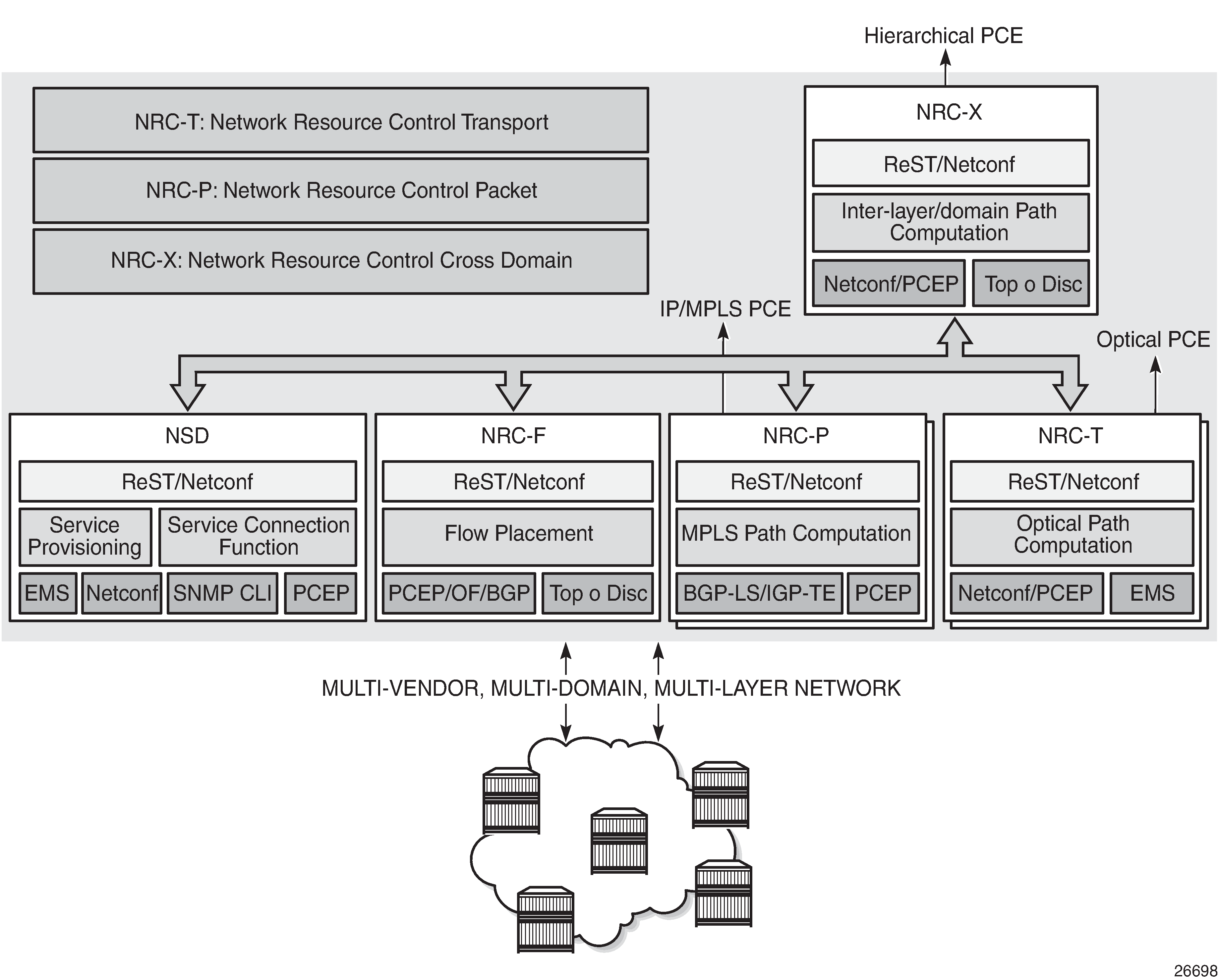
The two main components of the NSP are:
Network Services Director (NSD)
The NSD is a programmable and multi-vendor service provisioning tool that provides a single and simple API to the user and OSS. It implements a service model abstraction and adapts to each vendor-specific service model. It supports provisioning services such as E-Line, E-LAN, E-Tree, Layer 3 VPN, traffic steering, and service chaining.
Network Resource Controller (NRC)
The NRC implements separate modules for computing and managing optimal paths for optical tunnels (NRC-T) and MPLS tunnels (NRC-P), and for computing optimal routing and placement of IP flows (NRC-F). In addition, a resource controller for inter-layer IP and optical path computation and more complex inter-domain MPLS path computation is provided as part of the Network Resource Controller Cross Domain (NRC-X).
The Network Resource Controller - Packet (NRC-P) implements the stateful PCE for packet networks. The following figure shows the NRC-P architecture and its main components.
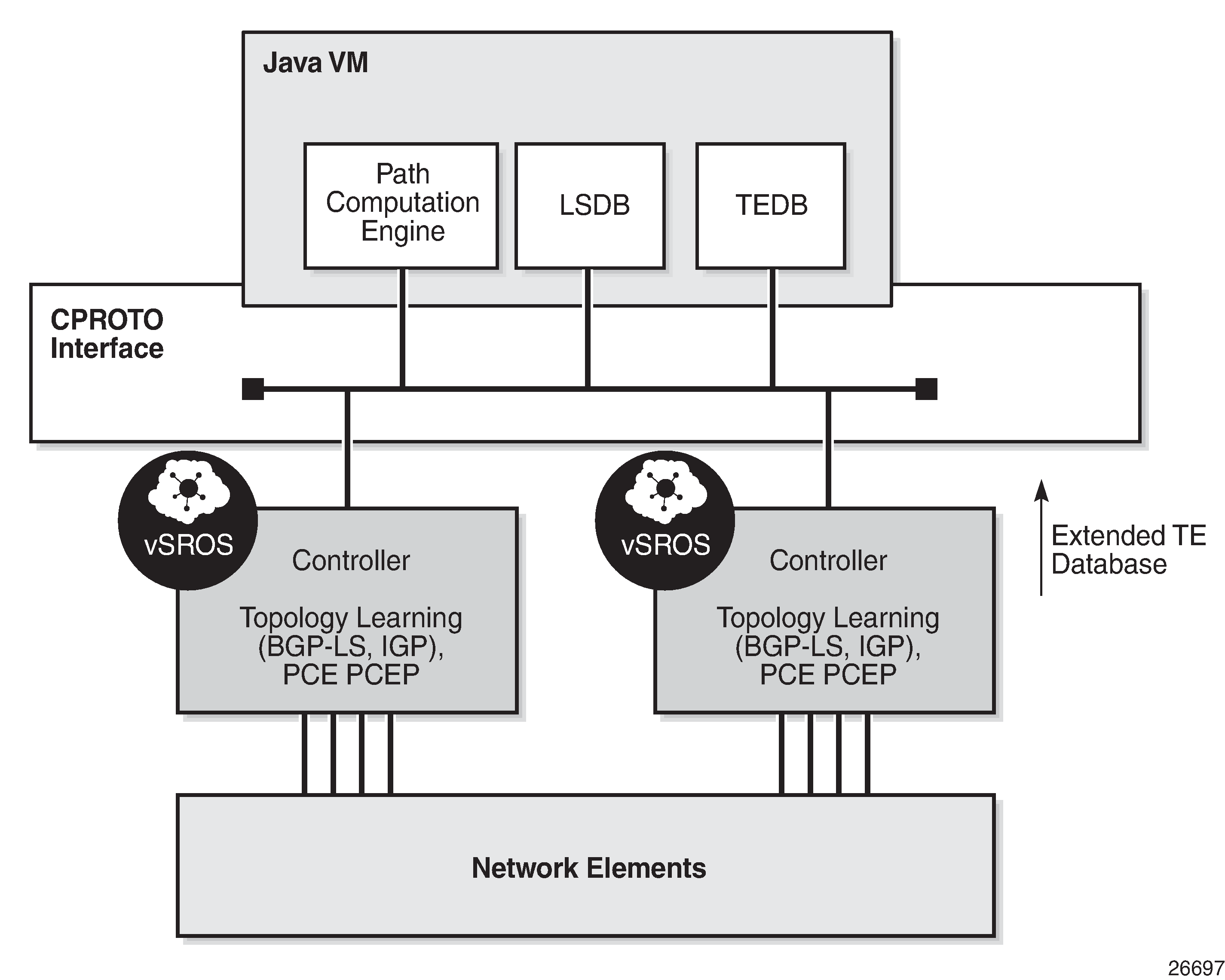
The NRC-P has the following architecture:
a single Virtual Machine (VM) handling the Java implementation of an MPLS path computation engine, a TE graph database, and an LSP database
a plug-in adapter with the Nokia CPROTO interface, providing reliable, TCP-based message delivery between vSROS and Java-VM. The plug-in adapter implements a compact encoding/decoding (codec) function for the message content using Google ProtoBuf. Google ProtoBuf also provides for automatic C++ (vSROS side) and Java (Java-VM side) code generation to process the exchanged message content.
a single VM running a vSROS image that handles the functions of topology discovery of multiple IGP instances and areas via IGP and NFM-P. For larger network domains, one VM running the vSROS image can be dedicated to a specific function.
The PCE module uses PCEP to communicate with its PCCs, and communicates with other PCEs to coordinate inter-domain path computation. Each router acting as a PCC initiates a PCEP session to the PCE in its domain.
When the user enables PCE control for one or more RSVP-TE LSPs, the PCE owns the path updating and periodic reoptimization of the LSPs. In this case, the PCE acts in an active stateful role. The PCE can also act in a passive stateful role for other LSPs on the router by discovering the LSPs and taking into account their resource consumption when computing the path for the LSPs it has control ownership of.
The following is a high-level description of the PCE and PCC capabilities:
base PCEP implementation, as defined in RFC 5440
active and passive stateful PCE LSP update, as defined in draft-ietf-pce-stateful-pce
delegation of LSP control to the PCE
synchronization of the LSP database with network elements for PCE-controlled LSPs and network element-controlled LSPs
support for PCC-initiated LSPs, as defined in draft-ietf-pce-stateful-pce
support for LSP path diversity across different LERs using extensions to the PCE path profile, as defined in draft-alvarez-pce-path-profiles
support for LSP path bidirectionality constraints using extensions to the PCE path profile, as defined in draft-alvarez-pce-path-profiles
Base implementation of PCE
The base implementation of the PCE uses the PCEP extensions defined in RFC 5440.
The main functions of PCEP are:
PCEP session establishment, maintenance, and closing
path computation requests using the PCReq message
path computation replies using the PCRep message
notification messages (PCNtf) by which the PCEP speaker can inform its peer about events, such as path request cancellation by the PCC or path computation cancellation by the PCE
error messages (PCErr) by which the PCEP speaker can inform its peer about errors related to processing requests, message objects, or TLVs
The following table lists the base PCEP TLVs, objects, and messages.
TLV, object, or message |
Contained in object |
Contained in message |
|---|---|---|
OPEN Object |
N/A |
OPEN, PCErr |
Request Parameter (RP) Object |
N/A |
PCReq, PCRep, PCErr, PCNtf |
NO-PATH Object |
N/A |
PCRep |
END-POINTS Object |
N/A |
PCReq |
BANDWIDTH Object |
N/A |
PCReq, PCRep, PCRpt1 |
METRIC Object |
N/A |
PCReq, PCRep, PCRpt1 |
Explicit Route Object (ERO) |
N/A |
PCRep |
Reported Route Object (RRO) |
N/A |
PCRpt1 |
LSPA Object |
N/A |
PCReq, PCRep, PCRpt1 |
Include Route Object (IRO) |
N/A |
PCReq, PCRep |
SVEC Object |
N/A |
PCReq |
NOTIFICATION Object |
N/A |
PCNtf |
PCEP-ERROR Object |
N/A |
PCErr |
LOAD-BALANCING Object |
N/A |
PCReq |
CLOSE Object |
N/A |
CLOSE |
The behavior and limitations of the implementation of the objects in the preceding table are as follows:
The PCE treats all supported objects received in a PCReq message as mandatory, regardless of whether the P-flag in the object’s common header is set (mandatory object) or not (optional object).
The PCC implementation always sets the B-flag (B=1) in the metric object containing the hop metric value, which means that a bound value must be included in PCReq message. The PCE returns the computed value in the PCRep message with flags set identically to the PCReq message.
The PCC implementation always sets flags B=0 and C=1 in the metric object for the IGP or TE metric values in the PCReq message. This means that the request is to optimize (minimize) the metric without providing a bound value. The PCE returns the computed value in the PCRep message with flags set identically to the PCReq message.
The IRO and LOAD-BALANCING objects are not part of the NSP PCE feature. If the PCE receives a PCReq message with one or more of these objects, it ignores them regardless of the setting of the P-flag, and processes the path computations normally.
The LSPA, metric, and bandwidth objects are also included in the PCRpt message. The inclusion of these objects in the PCRpt message is proprietary to Nokia.
The following features are not supported on the 7210 SAS:
PCE discovery using IS-IS, as defined in RFC 5089, and OSPF, as defined in RFC 5088, along with corresponding extensions for discovering stateful PCE, as defined in draft-sivabalan-pce-disco-stateful
security of the PCEP session using MD5 or TLS between PCEP peers
PCEP synchronization optimization as defined in draft-ietf-pce-stateful-sync-optimizations
support of end-to-end secondary backup paths for an LSP. PCE standards do not currently support an LSP container with multiple paths, and the PCE treats each request as a path with a unique PLSP-ID. It is up to the router to tie the two paths together to create 1:1 protection and to request path or SRLG diversity among them when it makes the request to the PCE.
jitter, latency, and packet loss metrics support as defined in RFC 7471 and draft-ietf-isis-te-metric-extensions, and their use in the PCE metric object as defined in draft-ietf-pce-pcep-service-aware
PCEP session establishment and maintenance
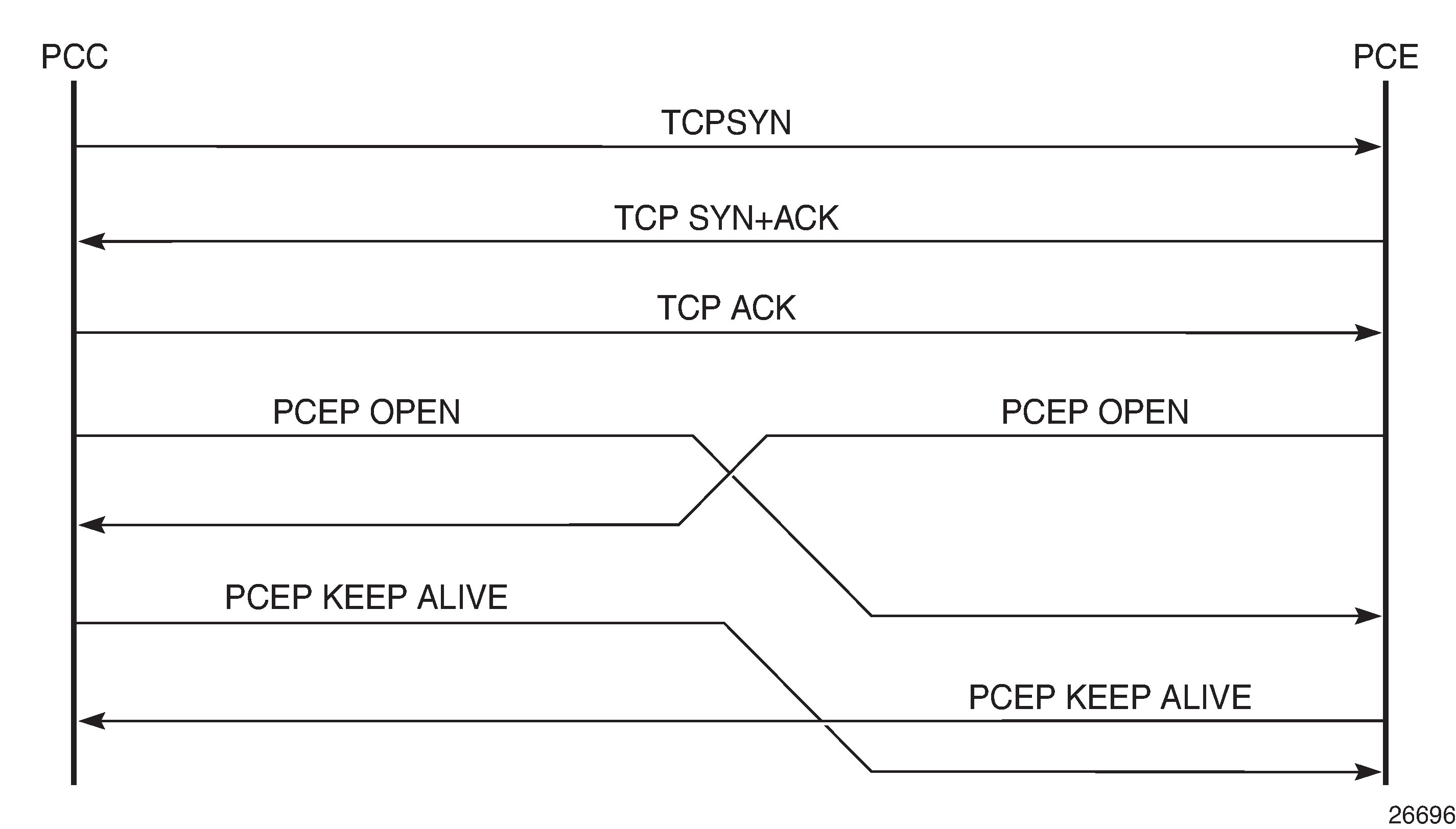
PCEP operates over TCP using destination TCP port 4189. The PCC always initiates the connection. When the user configures the PCEP local address and the peer address on the PCC, the PCC initiates a TCP connection to the PCE. When a connection is established, the PCC and PCE exchange OPEN messages, which initializes the PCEP session and exchanges the session parameters to be negotiated.
The PCC always tries to reach the remote PCE address in-band; the local address configured by the user is used for in-band sessions.
A keepalive mechanism is used as an acknowledgment of the acceptance of the session within the negotiated parameters. It is also used as a maintenance function to detect whether the PCEP peer is still alive.
The negotiated parameters include the keepalive timer and the dead-timer, and one or more PCEP capabilities such as support of stateful PCE and the LSP Path type.
The following figure shows the PCEP session initialization steps.
If the session to the PCE times out, the router acting as a PCC keeps the last successfully programmed path provided by the PCE until the session to the PCE is reestablished. Any subsequent change to the LSP state is synchronized at the time the session is reestablished.
When a PCEP session to a peer times out or closes, the rate at which the PCEP speaker attempts to reestablish the session is subject to an exponential back-off mechanism.
PCEP parameters
The following PCEP parameters are user-configurable on the PCC:
keepalive timer
A PCEP speaker must send a keepalive message if no other PCEP message is sent to the peer at the expiry of this timer. This timer is restarted every time a PCEP message is sent or the keepalive message is sent.
The keepalive mechanism is asymmetric, which allows each peer to use a different keepalive timer value.
The range of this timer is 1 to 255 seconds and the default value is 30 seconds.
dead timer
This timer tracks the amount of time a PCEP speaker waits after the receipt of the last PCEP message before declaring its peer down.
The dead timer mechanism is asymmetric, which allows each PCEP speaker to propose a different dead timer value to its peer to detect session timeouts.
The range of this timer is 1 to 255 seconds and the default value is 120 seconds.
maximum rate of unknown messages
When the rate of received unrecognized or unknown messages reaches the configured limit, the PCEP speaker closes the session to the peer.
The range of this message rate is 1 to 255 messages per minute and the default value is 10 messages per minute.
session reestablishment and state timeout
If the PCEP session to the PCE goes down, all delegated PCC-initiated LSPs have their state maintained in the PCC and are not timed out. The PCC continues to try reestablishing the PCEP session. When the PCEP session is reestablished, the LSP database is synchronized with the PCE database, and any LSP that went down since the last time the PCEP session was up has its path updated by the PCE.
PCC configuration
The following PCC parameters can be modified while the PCEP session is operational:
report-path-constraints
unknown-message-rate
The following PCC parameters cannot be modified while the PCEP session is operational:
local-address
keepalive
dead-timer
peer (regardless of shutdown state)
LSP initiation
An LSP that is configured on the router is referred to as a PCC-initiated LSP. An LSP that is not configured on the router, but is instead created by the PCE at the request of an application or a service instantiation, is referred to as a PCE-initiated LSP.
The 7210 SAS supports three modes of operation for PCC-initiated LSPs, which are configurable on a per-LSP basis:
PCC-initiated and PCC-controlled
When the path of the LSP is computed and updated by the router acting as a PCE Client (PCC), the LSP is referred to as PCC-initiated and PCC-controlled.
A PCC-initiated and PCC-controlled LSP has the following characteristics:
The LSP can contain strict or loose hops, or a combination of both.
CSPF is supported for RSVP-TE LSPs. Local path computation takes the form of hop-to-label translation for LSPs.
LSPs can be reported to synchronize the LSP database of a stateful PCE server using the pce-report option. In this case, the PCE acts in passive stateful mode for this LSP. The LSP path cannot be updated by the PCE. The control of the LSP is maintained by the PCC.
PCC-initiated and PCE-computed
When the path of the LSP is computed by the PCE at the request of the PCC, it is referred to as PCC-initiated and PCE-computed.
A PCC-initiated and PCE-computed LSP has the following characteristics:
The pce-computation option must be enabled for the LSP so that the PCE can perform path computation at the request of the PCC only. The PCC retains control.
LSPs can be reported to synchronize the LSP database of a stateful PCE server using the pce-report option. In this case, the PCE acts in passive stateful mode for this LSP.
PCC-initiated and PCE-controlled
When the path of the LSP is updated by the PCE following a delegation from the PCC, it is referred to as PCC-initiated and PCE-controlled.
A PCC-initiated and PCE-controlled LSP has the following characteristics:
The pce-control option must be enabled for the LSP so that the PCE can perform path updates following a network event without an explicit request from the PCC. The PCC delegates full control.
The pce-report option must be enabled for LSPs that cannot be delegated to the PCE. The PCE acts in active stateful mode for this LSP.
PCC-initiated and PCE-computed or PCE-controlled LSPs
The following is the procedure for configuring and programming a PCC-initiated LSP when control is delegated to the PCE:
The LSP configuration is created on the PE router via CLI or via the OSS/NSP NFM-P.
The configuration dictates which PCE control mode is needed: active (pce-control and pce-report options enabled) or passive (pce-computation enabled and pce-control disabled).
PCC assigns a unique PLSP-ID to the LSP. The PLSP-ID uniquely identifies the LSP on a PCEP session and must remain constant during its lifetime. PCC on the router must keep track of the association of the PLSP-ID to the Tunnel-ID and Path-ID, and use the latter to communicate with MPLS about a specific path of the LSP. PCC also uses the SRP-ID to correlate PCRpt messages for each new path of the LSP.
The PE router does not validate the entered path. However, in the 7210 SAS, the PCE supports the computation of a path for an LSP with empty-hops in its path definition. While PCC will include the IRO objects in the PCReq message to PCE, the PCE will ignore them and compute the path with the other constraints except the IRO.
The PE router sends a PCReq message to the PCE to request a path for the LSP, and includes the LSP parameters in the METRIC object, the LSPA object, and the BANDWIDTH object. The PE router also includes the LSP object with the assigned PLSP-ID. At this point, the PCC does not delegate the control of the LSP to the PCE.
The PCE computes a new path, reserves the bandwidth, and returns the path in a PCRep message with the computed ERO in the ERO object. It also includes the LSP object with the unique PLSP-ID, the METRIC object with any computed metric value, and the BANDWIDTH object.
Note:To enable the PCE to use the SRLG path diversity and admin-group constraints in the path computation, the user must configure the SRLG and admin-group membership against the MPLS interface and enable the traffic-engineering option in IGP. This causes IGP to flood the link SRLG and admin-group membership in its participating area, and for the PCE to learn it in its TE database.
The PE router updates the CPM and the datapath with the new path.
Up to this step, the PCC and PCE are using passive stateful PCE procedures. The next steps will synchronize the LSP database of the PCC and PCE for both PCE-computed and PCE-controlled LSPs. They will also initiate the active PCE stateful procedures for the PCE-controlled LSP only.
The PE router sends a PCRpt message to update the PCE with an Up state, and also sends the RRO as confirmation. It now includes the LSP object with the unique PLSP-ID. For a PCE-controlled LSP, the PE router also sets the delegation control flag to delegate control to the PCE. The state of the LSP is now synchronized between the router and the PCE.
Following a network event or a reoptimization, the PCE computes a new path for a PCE-controlled LSP and returns it in a PCUpd message with the new ERO. It will include the LSP object with the same unique PLSP-ID assigned by the PCC, as well as the Stateful Request Parameter (SRP) object with a unique SRP-ID-number to track error and state messages specific to this new path.
The PE router updates the CPM and the datapath with the new path.
The PE router sends a PCRpt message to inform the PCE that the older path is deleted. It includes the unique PLSP-ID value in the LSP object and the R (Remove) bit set.
The PE router sends a new PCRpt message to update PCE with an Up state, and also sends the RRO to confirm the new path. The state of the LSP is now synchronized between the router and the PCE.
If PCE owns the delegation of the LSP and is making a path update, MPLS will initiate the LSP and update the operational value of the changed parameters while the configured administrative values will not change. Both the administrative and operational values are shown in the details of the LSP path in MPLS.
If the user makes any configuration change to the PCE-computed or PCE-controlled LSP, MPLS requests that the PCC first revoke delegation in a PCRpt message (PCE-controlled only), and then MPLS and PCC follow the above steps to convey the changed constraint to PCE which will result in the programming of a new path into the datapath, the synchronization of the PCC and PCE LSP databases, and the return of delegation to PCE.
The preceding procedure is followed when the user performs a no shutdown command on a PCE-controlled or PCE-computed LSP. The starting point is an LSP which is administratively down with no active path. For an LSP with an active path, the following items may apply:
-
If the user has enabled the pce-computation option on a PCC-controlled LSP with an active path, no action is performed until the next time the router needs a path for the LSP following a network event of a LSP parameter change. At that point, the prior procedure is followed.
-
If the user has enabled the pce-control option on a PCC-controlled or PCE-computed LSP with an active path, the PCC will issue a PCRpt message to the PCE with an Up state, as well as the RRO of the active path. It will set the delegation control flag to delegate control to the PCE. The PCE will keep the active path of the LSP and make no updates to it until the next network event or reoptimization. At that point, the prior procedure is followed.
PCEP support for RSVP-TE LSPs
This section describes the support of PCC-initiated RSVP-TE LSPs. PCEP support of an RSVP-TE LSP is described in LSP initiation with the following differences:
-
each primary and secondary path is assigned its own unique path LSP-ID (PLSP-ID)
-
the PCC indicates to the PCE the state of each path (either up or down) and which path is currently active and carrying traffic (active state)
RSVP-TE LSP configuration for a PCC router
The following MPLS-level and LSP-level CLI commands are used to configure RSVP-TE LSPs in a router acting as a PCEP Client (PCC).
config>router>mpls>
pce-report rsvp-te {enable | disable}
config>router>mpls>lsp>
path-profile profile-id [path-group group-id]
pce-computation
pce-control
pce-report {enable | disable | inherit}
The cspf option must be enabled on the LSP before the pce-computation or pce-control options can be enabled. An attempt to disable the cspf option on an RSVP-TE LSP that has the pce-computation or pce-control options enabled will be rejected.
If the LSP has disabled PCE reporting, either because of inheritance from the MPLS-level configuration or because of LSP-level configuration, enabling the pce-control option for the LSP has no effect. To help troubleshoot this situation, the output of the show commands for the LSP displays the operational values of both the pce-report and pce-control options.
The PCE function implemented in the NSP and referred to as the NRC-P, supports only Shared Explicit (SE) style bandwidth management for RSVP-TE LSPs. The PCEP does not support the ability of the PCC to convey this value to the PCE. Therefore, whether the LSP configuration option rsvp-resv-style is set to se or ff, the PCE will always use the SE style in the CSPF computation of the path for a PCE-computed or PCE-controlled RSVP-TE LSP.
A manual bypass LSP does not support any of the PCE-related commands. Reporting a bypass LSP to the PCE is not required because the bypass LSP does not book bandwidth.
All other MPLS, LSP, and path-level commands are supported, with the exception of the following commands:
least-fill
srlg (on secondary standby path)
For more information about RSVP-TE PCC instantiation modes, see LSP initiation.
Behavior of the LSP path update
When the pce-control option is enabled, the PCC delegates control of the RSVP-TE LSP to the PCE.
The NRC-P sends a path update using the PCUpd message in the following cases:
a failure event that impacts a link or a node in the path of a PCE-controlled LSP
The operation is performed by the PCC as a Make-Before-Break (MBB) if the LSP remained in the up state because of protection provided by FRR or a secondary path. If the LSP went down, the update brings it into the up state. A PCRpt message is sent by the PCC for each change to the state of the LSP during this process. See Behavior of LSP MBB for more information.
a topology change that impacts a link in the path of a PCE-controlled LSP
This topology change can be a change to the IGP metric, the TE metric, admin-group, or SRLG membership of an interface. This update is performed as an MBB by the PCC.
the user has performed a manual resignal of a PCE-controlled RSVP-TE LSP path from the NRC-P
This update is performed as an MBB by the PCC.
the user has performed a Global Concurrent Optimization (GCO) on a set of PCE-controlled RSVP-TE LSPs from the NRC-P
This update is performed as an MBB by the PCC.
The procedures for the path update are described in LSP initiation. However, for an RSVP-TE LSP, the PCUpd message from the PCE contains the interface IP address or system IP address in the computed ERO. The PCC signals the path using the ERO returned by the PCE and, if successful, programs the datapath, then sends the PCRpt message with the resulting RRO and hop labels provided by RSVP-TE signaling.
If the signaling of the ERO fails, the ingress LER returns a PCErr message to the PCE with the LSP Error code field of the LSP-ERROR-CODE TLV set to a value of 8 (RSVP signaling error).
If the no adaptive option is set for the RSVP-TE LSP, the ingress LER cannot perform an MBB for the LSP. A PCUpd message received from the PCE is then failed by the ingress LER, which returns a PCErr message to the PCE with the LSP Error code field of the LSP-ERROR-CODE TLV set to a value of 8 (RSVP signaling error).
Path update with empty ERO
When the NRC-P reoptimizes the path of a PCE-controlled RSVP-TE LSP, it is possible that a path that satisfies the constraints of the LSP no longer exists. In this case, the NRC-P sends a PCUpd message with an empty ERO, which forces the PCC to bring down the path of the RSVP-TE LSP.
The NRC-P sends a PCUpd message with an empty ERO if any of the following cases are true:
The requested bandwidth is the same as the current bandwidth, which avoids bringing down the path because of a resignal during an MBB transition.
Local protection is not currently in use, which avoids bringing down a path that activated an FRR backup path. The LSP can remain on the FRR backup path until a new primary path can be found by the NRC-P.
The links of the current path are all operationally up, which allows the NRC-P to ensure that the RSVP control plane will report the path down when a link is down and not prematurely bring the path down with an empty ERO.
Behavior of LSP MBB
In addition to the MBB support when the PCC receives a path update, as described in Behavior of the LSP path update, an RSVP-TE LSP supports the MBB procedure for any parameter configuration change, including the PCEP-related commands when they result in a change to the path of the LSP.
If the user adds or modifies the path-profile command for an RSVP-TE LSP, a configuration change MBB is only performed if the pce-computation, pce-report, or pce-control options are enabled on the LSP. Otherwise, no action occurs. When pce-computation, pce-report, or pce-control are enabled on the LSP, the path update MBB (tools>perform>router>mpls>update-path) fails, resulting in no operation.
MBB is also supported for the manual resignal MBB type.
If the LSP goes into an MBB state at the ingress LER, the behavior is dependent on the operating mode of the LSP.
PCC-controlled LSPs
All MBB types are supported for PCC-controlled LSPs. The LSP MBB actions for a PCC-controlled LSP (pce-computation and pce-control disabled) are as follows:
MPLS submits a path request, including the updated path constraints, to the local CSPF.
If the local CSPF returns a path, the PCC signals the LSP with the RSVP control plane and moves traffic to the new MBB path. If pce-report is enabled for this LSP, the PCC sends a PCRpt message with the delegation bit clear to retain control and containing the RRO and LSP objects, with the LSP-IDENTIFIERS TLV containing the LSP-ID of the new MBB path. The message includes the metric, LSPA, and bandwidth objects where the P-flag is clear, which indicates the operational values of these parameters. Unless the user disables the report-path-constraints option under the pcc context, the PCC also includes a second set of metric, LSPA, and bandwidth objects with the P-flag set to convey to the PCE the constraints of the path.
If the CSPF returns no path or the RSVP-TE signaling of the returned path fails, MPLS puts the LSP into retry mode and sends a request to the local CSPF every retry-timer seconds and up to the value of retry-count.
When pce-report is enabled for the LSP and the FRR global revertive MBB is triggered following a bypass LSP activation by a PLR in the network, the PCC issues an updated PCRpt message with the new RRO reflecting the PLR and RRO hops. The PCE releases the bandwidth on the links that are no longer used by the LSP path.
PCE-computed LSPs
All MBB types are supported for PCE-computed LSPs. The LSP MBB actions for a PCE-computed LSP (pce-computation enabled and pce-control disabled) are as follows:
The PCC issues a PCReq for the same PLSP-ID and includes the updated constraints in the metric, LSPA, and bandwidth objects.
If the PCE successfully finds a path, it replies with a PCRep message with the ERO.
If the PCE does not find a path, it replies with a PCRep message containing the No-Path object.
If the PCE returns a path, the PCC signals the LSP with the RSVP control plane and moves traffic to the new MBB path. If pce-report is enabled for this LSP, the PCC sends a PCRpt message with the delegation D-bit clear to retain control and containing the RRO and LSP objects, with the LSP-IDENTIFIERS TLV containing the LSP-ID of the new MBB path. The message includes the metric, LSPA, and bandwidth objects where the P-flag is clear, which indicates the operational values of these parameters. Unless the user disables the report-path-constraints option under the pcc context, the PCC also includes a second set of metric, LSPA, and bandwidth objects with the P-flag set to convey to the PCE the constraints of the path.
If the PCE returns no path or the RSVP-TE signaling of the returned path fails, MPLS puts the LSP into retry mode and sends a request to PCE every retry-timer seconds and up to the value of retry-count.
When the pce-report is enabled for the LSP and the FRR global revertive MBB is triggered following a bypass LSP activation by a PLR in the network, the PCC issues an updated PCRpt message with the new RRO reflecting the PLR and RRO hops. The PCE releases the bandwidth on the links that are no longer used by the LSP path.
If the user changes the RSVP-TE LSP configuration from pce-computation to no pce-computation, MBB procedures are not supported. In this case, the LSP path is torn down and is put into retry mode to compute a new path from the local CSPF on the router to signal the LSP.
PCE-controlled LSPs
The LSP MBB actions for a PCE-controlled LSP (pce-control enabled) are as follows:
Items 1 through 5 of the following procedure apply to the config change, and manual resignal MBB types. The delayed retry MBB type used with the SRLG on secondary standby LSP feature is not supported with a PCE-controlled LSP. See Behavior of secondary LSP paths for information about the SRLG on secondary standby LSP feature.
The PCC temporarily removes delegation by sending a PCRpt message for the corresponding path LSP-ID (PLSP-ID) with the delegation D-bit clear.
For an LSP with pce-computation disabled, MPLS submits a path request to the local CSPF, which includes the updated path constraints.
For an LSP with pce-computation enabled, the PCC issues a PCReq for the same PLSP-ID and includes the updated constraints in the metric, LSPA, or bandwidth objects:
If the PCE successfully finds a path, it replies with a PCRep message with the ERO.
If the PCE does not find a path, it replies with a PCRep message containing the No-Path object.
If the local CSPF or the PCE returns a path, the PCC performs the following actions:
The PCC signals the LSP with the RSVP control plane and moves traffic to the new MBB path. It then sends a PCRpt message with the delegation D-bit set to return delegation and containing the RRO and LSP objects, with the LSP-IDENTIFIERS TLV containing the LSP-ID of the new MBB path. The message includes the metric, LSPA, and bandwidth objects where the P-flag is clear, which indicates the operational values of these parameters. Unless the user disabled the report-path-constraints option under the pcc context, the PCC also includes a second set of metric, LSPA, or bandwidth objects with the P-flag set to convey to the PCE the constraints of the path.
The PCC sends a PathTear message to delete the state of the older path in the network. The PCC then sends a PCRpt message to the PCE with the older path LSP (PLSP-ID) and the remove R-bit set to also have the PCE remove the state of that LSP from its database.
If the local CSPF or the PCE returns no path or the RSVP-TE signaling of the returned path fails, the router makes no further requests. That is, there is no retry for the MBB:
The PCC sends a PCErr message to the PCE with the LSP Error code field of the LSP-ERROR-CODE TLV set to a value of 8 (RSVP signaling error) if the MBB failed because of a RSVP-TE signaling error.
The PCC sends a PCRpt message with the delegation D-bit set to return delegation and containing the RRO and LSP objects, with the LSP-IDENTIFIERS TLV containing the LSP-ID of the currently active path. The message includes the metric, LSPA, and bandwidth objects where the P-flag is clear to indicate the operational values of these parameters. Unless the user disabled the report-path-constraints option under the pcc context, the PCC also includes a second set of metric, LSPA, and bandwidth objects with the P-flag set to convey to the PCE the constraints of the path.
The ingress LER takes no action in the case of a network event triggered MBB, such as FRR global revertive or TE graceful shutdown:
The ingress PE keeps the information as required and sets the state of MBB to one of the FRR global revertive or TE graceful shutdown MBB values but does not perform the MBB action.
The NRC-P computes a new path for the global revertive MBB because of a failure event. This computation uses the PCUpd message to update the path using the MBB procedure described in Behavior of the LSP path update. The activation of a bypass LSP by a point of local repair (PLR) in the network causes the PCC to issue an updated PCRpt message with the new RRO reflecting the PLR and RRO hops. The PCE will release the bandwidth on the links that are no longer used by the LSP path.
The NRC-P computes a new path for the TE graceful shutdown MBB if the RSVP-TE is using the TE metric, because the TE metric of the link in TE graceful shutdown is set to infinity. This computation uses the PCUpd message to update the path using the MBB procedure described in Behavior of the LSP path update.
The NRC-P does not act on the TE graceful shutdown MBB if the RSVP-TE is using the IGP metric; however, the user can perform a manual resignal of the LSP path from the NRC-P to force a new path computation, which accounts for the newly available bandwidth on the link that caused the MBB event. This computation uses the PCUpd message to update the path using the MBB procedure described in Behavior of the LSP path update.
The user can perform a manual resignal of the LSP path from the ingress LER, which forces an MBB for the path as per the remove-delegation/MBB/return-delegation procedures described in this section.
If the user performs no pce-control while the LSP still has the state for any of the network event triggered MBBs, the MBB is performed immediately by the PCC as described in the procedures in PCE-computed LSPs for a PCE-computed LSP and as described in the procedures in PCC-controlled LSPs for a PCC-controlled LSP.
The timer-based manual resignal MBB behaves like the TE graceful shutdown MBB. The user can perform a manual resignal of the LSP path from the ingress LER or from the PCE.
The path update MBB (tools>perform>router>mpls>update-path) fails, which results in no operation. This is true in all cases when the RSVP-TE LSP enables the pce-report option.
Behavior of secondary LSP paths
Each of the primary, secondary standby, and secondary non-standby paths of the same LSP must use a separate path LSP-ID (PLSP-ID). The PCE function of the NSP, the NRC-P, checks the LSP-IDENTIFIERS TLV in the LSP object and can identify which PLSP-IDs are associated with the same LSP or the same RSVP-TE session. The parameters are the IPv4 Tunnel Sender Address, the Tunnel ID, the Extended Tunnel ID, and the IPv4 Tunnel Endpoint Address. This approach allows the use of all the PCEP procedures for all three types of LSP paths.
The PCC indicates to the PCE the following states for the path in the LSP object: down, up (signaled but not carrying traffic), or active (signaled and carrying traffic).
The PCE tracks active paths and displays them in the NSP GUI. It also provides only the tunnel ID of an active PLSP-ID to a destination prefix when a request is made by a service or a steering application.
The PCE recomputes the paths of all PLSP-IDs that are affected by a network event. The user can select each path separately on the NSP GUI and trigger a manual resignal of one or more paths of the RSVP-TE LSP.
Enabling the srlg option on a secondary standby path results in no operation. The NRC-P supports link and SRLG disjointedness using the PCE path profile. The user can apply the PCE path profile to the primary and secondary paths of the same LSP. See PCE path profile support for more information.
PCE path profile support
The PCE path profile ID and path group ID are configured at the LSP level (config>router>mpls>lsp>path-profile).
The NRC-P can enforce path disjointedness and bidirectionality among a pair of forward and a pair of reverse LSP paths. Both pairs of LSP paths must use a unique path group ID along with the same path profile ID.
If the user wants to apply path disjointedness and path bidirectionality constraints to RSVP-TE LSP paths, it is important to follow the following guidelines. The user can configure the following sets of LSP paths:
a set consisting of a pair of forward RSVP-TE LSPs and a pair of reverse RSVP-TE LSPs, each with a single primary or secondary path. The pair of forward LSPs can originate and terminate on different routers. The pair of reverse LSPs must mirror the forward pair. In this case, the path profile ID and the path group ID configured for each LSP must match. Because each LSP has a single path, the bidirectionality constraint applies automatically to the forward and reverse LSPs, which share the same originating node and the same terminating routers.
a pair consisting of a forward RSVP-TE LSP and a reverse RSVP-TE LSP, each with a primary path and a single secondary path, or each with two secondary paths. Because the two paths of each LSP inherit the same LSP level path profile ID and path group ID configuration, the NRC-P path computation algorithm cannot guarantee that the primary paths in both directions meet the bidirectionality constraint. That is, it is possible that the primary path for the forward LSP shares the same links as the secondary path of the reverse LSP and the other way around.
LSP path diversity and bidirectionality constraints
The PCE path profile defined in draft-alvarez-pce-path-profiles is used to request path diversity or a disjoint for two or more LSPs originating on the same or different PE routers. It is also used to request that paths of two unidirectional LSPs between the same two routers use the same TE links. This is referred to as the bidirectionality constraint.
Path profiles are defined directly on the NRC-P Policy Manager with a number of LSP path constraints, which are metrics with upper bounds specified, and with an objective, which are metrics optimized with no bounds specified. The NRC-P Policy Manager allows the following PCE constraints to be configured within each PCE path profile:
path diversity, node-disjoint, link-disjoint
path bidirectionality, symmetric reverse route preferred, symmetric reverse route required
maximum path IGP metric (cost)
maximum path TE metric
maximum hop count
The user can also specify the PCE objective used to optimize the path of the LSP in the PCE path profile, one of:
IGP metric (cost)
TE metric
hops (span)
The CSPF algorithm will optimize the objective. If a constraint is provided for the same metric, the CSPF algorithm ensures that the selected path achieves a lower or equal value to the bound value specified in the constraint.
For hop-count metrics, if a constraint is sent in a metric object and is also specified in a PCE profile referenced by the LSP, the constraint in the metric object is used.
For IGP and TE metrics, if an objective is sent in a metric object and is also specified in a PCE profile referenced by the LSP, the objective in the path profile is used.
The constraints in the bandwidth object and the LSPA object, specifically the include and exclude admin-group constraints and setup and hold priorities, are not supported in the PCE profile.
To indicate the path diversity and bidirectionality constraints to the PCE, the user must configure the profile ID and path group ID of the PCE path to which the LSP belongs. The path group ID does not need to be defined in the PCE as part of the path profile configuration and identifies implicitly the set of paths that must have the path diversity constraint applied.
The user can only associate a single path group ID with a specific PCE path profile ID for an LSP. However, the same path group ID can be associated with multiple PCE profile IDs for the same LSP.
The path profiles are inferred using the path ID in the path request by the PCC. When the PE router acting as a PCC wants to request path diversity from a set of other LSPs belonging to a path group ID value, it adds a new PATH-PROFILE object in the PCReq message. The object contains the path profile ID and the path group ID as an extended ID field. In other words, the diversity metric is carried in an opaque way from the PCC to the PCE.
The bidirectionality constraint operates the same way as the diversity constraint. The user can configure a PCE profile with both the path diversity and bidirectionality constraints. The PCE will check if there is an LSP in the reverse direction that belongs to the same path group ID as an originating LSP it is computing the path for, and will enforce the constraint.
To ensure that the PCE is aware of the path diversity and bidirectionality constraints for an LSP that is delegated but for which there is no prior state in the NRC-P LSP database, the PATH-PROFILE object is included in the PCRpt message with the P-flag set in the common header to indicate that the object must be processed. This is proprietary to Nokia.
The following table lists the new objects and TLVs introduced in the PCE path profile.
TLV, object, or message |
Contained in object |
Contained in message |
|---|---|---|
PATH-PROFILE-CAPABILITY TLV |
OPEN |
OPEN |
PATH-PROFILE Object |
N/A |
PCReq, PCRpt2 |
A PATH-PROFILE object can contain multiple TLVs containing each profile ID and extend ID, and should be processed properly. If multiple PATH-PROFILE objects are received, the first object is interpreted and the others are ignored. The PCC and the PCE support all PCEP capability TLVs defined in this document and will always advertise them. If the OPEN object received from a PCEP speaker does not contain one or more of the capabilities, the PCE or PCC will not use them during that PCEP session.
PCEP configuration command reference
Command hierarchies
PCEP commands
config
    - router
        - [no] pcep
            - [no] pcc
                - dead-timer seconds
                - no dead-timer
                - keepalive seconds
                - no keepalive
                - local-address ip-address
                - no local-address
                - [no] peer ip-address
                    - [no] shutdown
                - [no] report-path-constraints
                - [no] shutdown
                - unknown-message-rate msg/min
                - no unknown-message-rate
Show commands
show
    - router
        - pcep
            - pcc
                - detail
                - lsp-db [lsp-type lsp_type] [delegated-pce ip-address]
                - lsp-db [lsp-type lsp_type] from ip-address [delegated-pce ip-address]
                - lsp-db [lsp-type lsp_type] lsp lsp-name [delegated-pce ip-address]
                - lsp-db [lsp-type lsp_type] to ip-address [tunnel-id [tunnel-id]]
                - lsp-db [lsp-type lsp_type] tunnel-id [tunnel-id]
                - path-request [lsp-type {rsvp-p2p}] [dest ip-address] [detail]
                - peer [ip-address] [detail]
                - status
Tools commands
Command descriptions
PCEP commands
pcep
Syntax
[no] pcep
Context
config>router
Platforms
Supported on all 7210 SAS platforms as described in this document
Description
This command enables the Path Computation Element Communication Protocol (PCEP) and enters the context to configure PCEP parameters.
The no form of this command disables PCEP.
pcc
Syntax
[no] pcc
Context
config>router>pcep
Platforms
Supported on all 7210 SAS platforms as described in this document
Description
Commands in this context configure PCC parameters.
The no form of this command disables PCC.
dead-timer
Syntax
dead-timer seconds
no dead-timer
Context
config>router>pcep>pcc
Platforms
Supported on all 7210 SAS platforms as described in this document
Description
This command configures the PCEP session dead-timer value, which is the amount of time a PCEP speaker waits after the receipt of the last PCEP message before declaring its peer down.
The dead-timer mechanism is asymmetric, which means that each PCEP speaker can propose a different dead-timer value to its peer to use to detect session timeout.
The no form of this command reverts to the default value.
Default
120
Parameters
- seconds
Specifies the dead timer value, in seconds.
keepalive
Syntax
keepalive seconds
no keepalive
Context
config>router>pcep>pcc
Platforms
Supported on all 7210 SAS platforms as described in this document
Description
This command configures the PCEP session keepalive value. A PCEP speaker must send a keepalive message if no other PCEP message is sent to the peer at the expiry of this timer. This timer is restarted every time a PCEP message or keepalive message is sent.
The keepalive mechanism is asymmetric, which means that each peer can use a different keepalive timer value at its end.
The no form of this command reverts to the default value.
Default
30
Parameters
- seconds
Specifies the keepalive value, in seconds.
local-address
Syntax
local-address ip-address
no local-address
Context
config>router>pcep>pcc
Platforms
Supported on all 7210 SAS platforms as described in this document
Description
This command configures the local address of the PCEP speaker.
The PCEP protocol operates over TCP using destination TCP port 4189. The PCE client (PCC) always initiates the connection. When the user configures the PCEP local address and the peer address on the PCC, the PCC initiates a TCP connection to the PCE. When the connection is established, the PCC and PCE exchange OPEN messages, which initializes the PCEP session and exchanges the session parameters to be negotiated.
The PCC checks if the remote PCE address is reachable in-band. Out-of-band sessions are not supported.
The no form of this command removes the configured local address of the PCEP speaker.
Parameters
- ip-address
Specifies the IP address of the PCEP speaker to be used for in-band sessions.
peer
Syntax
[no] peer ip-address
Context
config>router>pcep>pcc
Platforms
Supported on all 7210 SAS platforms as described in this document
Description
This command configures the IP address of a peer PCEP speaker. The address is used as the destination address in the PCEP session messages to a PCEP peer.
The no form of this command removes the specified peer PCEP speaker.
Parameters
- ip-address
Specifies the IP address of the PCEP peer to be used as the destination address in the PCEP session.
report-path-constraints
Syntax
[no] report-path-constraints
Context
config>router>pcep>pcc
Platforms
Supported on all 7210 SAS platforms as described in this document
Description
This command enables the inclusion of LSP path constraints in the PCE report messages sent from the PCC to a PCE.
For the PCE to know about the original constraints for an LSP that is delegated but for which there is no prior state in its LSP database (for example, if no PCReq message was sent for the same PLSP-ID), the following proprietary behavior applies:
The PCC appends a duplicate of each of the LSPA, metric, and bandwidth objects in the PCRpt message. The only difference between two objects of the same type is that the P-flag is set in the common header of the duplicate object to indicate that it is a mandatory object for processing by the PCE.
The value of the metric or bandwidth in the duplicate object contains the original constraint value, while the first object contains the operational value. This is applicable to hop metrics in the metric and bandwidth objects only. The 7210 SAS PCC does not support configuring a boundary on the path computation IGP or TE metrics.
The path computation on the PCE must use the first set of objects when updating a path if the PCRpt message contained a single set. If the PCRpt message contained a duplicate set, PCE path computation must use the constraints in the duplicate set.
The no form of this command disables the preceding behavior in case of interoperability issues with third-party PCE implementations.
Default
report-path-constraints
shutdown
Syntax
[no] shutdown
Context
config>router>pcep>pcc
config>router>pcep>pcc>peer
Platforms
Supported on all 7210 SAS platforms as described in this document
Description
This command administratively disables the PCC process.
The following PCC parameters can be modified without shutting down the PCEP session:
report-path-constraints
unknown-message-rate
The following PCC parameters can only be modified when the PCEP session is shut down:
local-address
keepalive
dead-timer
peer
The no form of this command administratively enables the PCC process.
Default
shutdown
unknown-message-rate
Syntax
unknown-message-rate msg/min
no unknown-message-rate
Context
config>router>pcep>pcc
Platforms
Supported on all 7210 SAS platforms as described in this document
Description
This command configures the maximum rate of unknown messages that can be received during a PCEP session.
When the rate of received unrecognized or unknown messages reaches the configured limit, the PCEP speaker closes the session to the peer.
The no form of this command reverts to the default value.
Default
10
Parameters
- msg/min
Specifies the rate of unknown messages, in messages per minute.
Show commands
The following command outputs are examples only; actual displays may differ depending on supported functionality and user configuration.
detail
Syntax
detail
Context
show>router>pcep>pcc
Platforms
Supported on all 7210 SAS platforms as described in this document
Description
This command displays PCEP PCC detailed information.
Output
The following output is an example of PCEP PCC detailed information, and Output fields: PCEP PCC describes the output fields.
Sample output*A:ZBG>show>router>pcep# pcc detail
===============================================================================
Path Computation Element Protocol (PCEP) Path Computation Client (PCC) Info
===============================================================================
Admin Status : Down Oper Status : Down
Unknown Msg Limit : 10 msg/min
Keepalive Interval : 50 seconds DeadTimer Interval : 150 seconds
Capabilities List : stateful-delegate stateful-pce rsvp-path
Address : 10.10.10.10
Report Path Constraints: True
Open Wait Timer : 60 seconds Keep Wait Timer : 60 seconds
Sync Timer : 60 seconds Request Timer : 120 seconds
Connection Timer : 60 seconds Allow Negotiations : False
Max Sessions : 1 Max Unknown Req : 1000
===============================================================================
*A:ZBG>show>router>pcep#
Label |
Description |
|---|---|
Admin Status |
The administrative status of the PCC |
Oper Status |
The operational status of the PCC |
Unknown Msg Limit |
The maximum rate of unknown messages that can be received on a PCEP session |
Keepalive Interval |
The specified keepalive interval for the PCEP session |
DeadTimer Interval |
The specified dead time interval for the PCEP session |
Capabilities List |
The capabilities list for the PCEP session |
Address |
The local IP address of the PCEP speaker |
Report Path Constraints |
Indicates whether to include LSP path constraints in the PCE report messages sent from the PCC to a PCE |
Open Wait Timer |
The value of the open wait timer for the PCEP session |
Keep Wait Timer |
The value of the keep wait timer for the PCEP session |
Sync Timer |
The value of the synchronization timer for the PCEP session |
Request Timer |
The value of the request timer for the PCEP session |
Connection Timer |
The value of the keep wait timer for the PCEP session |
Allow Negotiations |
Indicates where negotiations between PCEP PCC and PCE are allowed |
Max Sessions |
The maximum number of PCEP sessions on the router |
Max Unknown Req |
The maximum number of unknown requests for PCEP sessions on the router |
lsp-db
Syntax
lsp-db [lsp-type lsp_type] [delegated-pce ip-address]
lsp-db [lsp-type lsp_type] from ip-address [delegated-pce ip-address]
lsp-db [lsp-type lsp_type] lsp lsp-name [delegated-pce ip-address]
lsp-db [lsp-type lsp_type] to ip-address [tunnel-id [tunnel-id]]
lsp-db [lsp-type lsp_type] tunnel-id [tunnel-id]
Context
show>router>pcep>pcc
Platforms
Supported on all 7210 SAS platforms as described in this document
Description
This command displays PCEP PCC LSP information.
Parameters
- lsp_type
Specifies the type of LSP to display. The only available option is RSVP-TE point-to-point LSPs (rsvp-p2p).
- tunnel-id
Specifies a tunnel ID.
- ip-address
Specifies an IPv4 address.
Output
The following output is an example of PCEP PCC LSP information, and Output fields: PCEP PCC LSP describes the output fields.
Sample output*A:ZBG# show router pcep pcc lsp-db
===============================================================================
PCEP Path Computation Client (PCC) LSP Update Info
===============================================================================
PCEP-specific LSP ID: 1
LSP ID : 21504 LSP Type : rsvp-p2p
Tunnel ID : 1 Extended Tunnel Id : 10.20.1.3
LSP Name : test_lsp::fully_loose
Source Address : 10.20.1.3 Destination Address : 10.20.1.1
LSP Delegated : True Delegate PCE Address: 10.120.210.36
Oper Status : active
-------------------------------------------------------------------------------
PCEP-specific LSP ID: 2
LSP ID : 21510 LSP Type : rsvp-p2p
Tunnel ID : 1 Extended Tunnel Id : 10.20.1.3
LSP Name : test_lsp::stdby_fully_loose_2
Source Address : 10.20.1.3 Destination Address : 10.20.1.1
LSP Delegated : True Delegate PCE Address: 10.120.210.36
Oper Status : up
===============================================================================
*A:ZBG#
Label |
Description |
|---|---|
PCEP-specific LSP ID |
The PCEP-specific LSP identifier |
LSP ID |
The LSP identifier |
Tunnel ID |
The tunnel identifier for the LSP |
LSP Name |
The configured LSP name |
Source Address |
The source IP address of the LSP |
LSP Delegated |
The delegation status of the LSP |
Oper Status |
The operational status of the LSP |
LSP Type |
The type of the LSP |
Extended Tunnel Id |
The expanded tunnel identifier for the LSP |
Destination Address |
The destination IP address of the LSP |
Delegate PCE Address |
The IP address of the delegate PCE router |
path-request
Syntax
path-request [lsp-type {rsvp-p2p}] [dest ip-address] [detail]
Context
show>router>pcep>pcc
Platforms
Supported on all 7210 SAS platforms as described in this document
Description
This command displays PCEP PCC path request information.
Parameters
- lsp-type
Specifies the type of LSP to display. The only available option is RSVP-TE point-to-point LSPs.
- ip-address
Specifies the destination IPv4 address to display.
- detail
Displays detailed path request information.
Output
The following output is an example of PCEP PCC path request information, and Output fields: PCEP PCC path request describes the output fields.
Sample output*A:ZBG# show router pcep pcc path-request
===============================================================================
PCEP Path Computation Client (PCC) Path Computation Request (PCReq) Info
===============================================================================
Request ID : 4 Message State : sent-for-compute
Tunnel ID : 2 Extended Tunnel Id : 10.20.1.3
LSP ID : 62468 LSP Type : rsvp-p2p
LSP Name : test_lsp::fully_loose
Source Address : 10.20.1.3 Destination Address: 10.20.1.1
SVEC Id : 4 LSP Bandwidth : 0
===============================================================================
*A:ZBG#
Label |
Description |
|---|---|
Request ID |
The PCEP PCC path request identifier |
Tunnel ID |
The tunnel identifier for the LSP |
LSP ID |
The LSP identifier |
LSP Name |
The configured LSP name |
Source Address |
The source IP address of the LSP |
SVEC Id |
The synchronization vector identifier |
Message State |
The current state of the request |
Extended Tunnel Id |
The expanded tunnel identifier for the LSP |
LSP Type |
The type of the LSP |
Destination Address |
The destination IP address of the LSP |
LSP Bandwidth |
The bandwidth of the LSP |
peer
Syntax
peer [ip-address] [detail]
Context
show>router>pcep>pcc
Platforms
Supported on all 7210 SAS platforms as described in this document
Description
This command displays PCEP PCC peer information.
Parameters
- ip-address
Specifies a peer IPv4 address to display.
- detail
Displays detailed peer information.
Output
The following output is an example of a PCEP PCC peer information, and Output fields: PCEP PCC peer describes the output fields.
Sample output*A:ZBG>show>router>pcep>pcc# peer detail
===============================================================================
PCEP Path Computation Client (PCC) Peer Info
===============================================================================
IP Address : 10.10.10.11
Admin Status : Down Oper Status : Down
Peer Capabilities : (Not Specified)
Speaker ID : (Undefined)
Sync State : not-initialized Peer Overloaded : False
Session Establish Time: 0d 00:00:00
Oper Keepalive : N/A Oper DeadTimer : N/A
Session Setup Count : 0 Session Setup Fail Count: 0
-------------------------------------------------------------------------------
Statistics Information
-------------------------------------------------------------------------------
Sent Received
-------------------------------------------------------------------------------
PC Request Message 0 0
PC Reply Message 0 0
PC Error Message 0 0
PC Notification Message 0 0
PC Keepalive Message 0 0
PC Update Message 0 0
PC Report Message 0 0
Path Report 0 0
Path Request 0 0
-------------------------------------------------------------------------------
===============================================================================
*A:ZBG>show>router>pcep>pcc#
Label |
Description |
|---|---|
IP Address |
The IP address of the PCC peer |
Admin Status |
The administrative status of the PCC peer |
Oper Status |
The operational status of the PCC peer |
Peer Capabilities |
The PCEP capabilities of the PCC peer |
Speaker ID |
The IP address of the PCC peer speaker |
Sync State |
The synchronization state of the |
Peer Overloaded |
Indicates whether the PCC peer is overloaded |
Session Establish Time |
The length of time since the PCEP session was established |
Oper Keepalive |
The operational value for the PCC peer keepalive timer |
Oper DeadTimer |
The operational value for the PCC peer dead timer |
Session Setup Count |
The number of times that the PCEP session has been set up |
Session Setup Fail Count |
The number of times that the PCEP session failed to be set up |
Statistics Information |
|
PC Request Message |
The number of path computation (PC) request messages sent the PCC peer and received from the PCC peer |
PC Reply Message |
The number of PC reply messages sent to the PCC peer and received from the PCC peer |
PC Error Message |
The number of PC error messages sent to the PCC peer and received from the PCC peer |
PC Notification Message |
The number of PC notification messages sent to the PCC peer and received from the PCC peer |
PC Keepalive Message |
The number of PC keepalive messages sent to the PCC peer and received from the PCC peer |
PC Update Message |
The number of PC update messages sent to the PCC peer and received from the PCC peer |
PC Report Message |
The number of PC report messages sent to the PCC peer and received from the PCC peer |
Path Report |
The number of path reports sent to the PCC peer and received from the PCC peer |
Path Request |
The path requests sent to the PCC peer and received from the PCC peer |
status
Syntax
status
Context
show>router>pcep>pcc
Platforms
Supported on all 7210 SAS platforms as described in this document
Description
This command displays PCEP PCC status information.
Output
The following output is an example of PCEP PCC status information, and Output fields: PCEP PCC status describes the output fields.
Sample output*A:ZBG>show>router>pcep>pcc# status
===============================================================================
Path Computation Element Protocol (PCEP) Path Computation Client (PCC) Info
===============================================================================
Admin Status : Down Oper Status : Down
Unknown Msg Limit : 10 msg/min
Keepalive Interval : 50 seconds DeadTimer Interval : 150 seconds
Capabilities List : stateful-delegate stateful-pce rsvp-path
Address : 10.10.10.10
Report Path Constraints: True
-------------------------------------------------------------------------------
PCEP Path Computation Client (PCC) Peer Info
-------------------------------------------------------------------------------
Peer Admin State/Oper State Oper Keepalive/Oper DeadTimer
-------------------------------------------------------------------------------
10.10.10.11 Down/Down Not-Applicable/Not-Applicable
-------------------------------------------------------------------------------
===============================================================================
*A:ZBG>show>router>pcep>pcc#
Label |
Description |
|---|---|
Admin Status |
The administrative status of the PCC |
Oper Status |
The operational status of the PCC |
Unknown Msg Limit |
The maximum rate of unknown messages that can be received on a PCEP session |
Keepalive Interval |
The specified keepalive interval for the PCEP session |
DeadTimer Interval |
The specified dead time interval for the PCEP session |
Capabilities List |
The capabilities list for the PCEP session |
Address |
The local IP address of the PCEP speaker |
Report Path Constraints |
Indicates whether to include LSP path constraints in the PCE report messages sent from the PCC to a PCE |
PCEP Path Computation Client (PCC) peer info |
|
Peer |
The IP address of the PCC peer |
Admin State/Oper State |
The administrative and operational states of the PCC peer |
Oper Keepalive/Oper DeadTimer |
The operational keepalive and dead timer intervals of the PCC peer |
Tools commands
pcc
Syntax
pcc lsp [plsp-id plsp-id]
pcc lsp lsp-type lsp-type [tunnel-id tunnel-id]
Context
tools>dump>router>pcep
Platforms
Supported on all 7210 SAS platforms as described in this document
Description
This command displays PCEP PCC LSP information.
Parameters
- lsp
Keyword used to display LSP information.
- plsp-id
Specifies the ID of a PCC LSP. Only information for the PCC LSP with the specified ID is displayed.
- lsp-type
Specifies an LSP type. Only information for LSPs matching the specified type is displayed.
- tunnel-id
Specifies a tunnel ID. Only information for the tunnel with the specified ID is displayed.