QoS policies
This chapter provides information about QoS policies and mechanisms to classify, queue, shape, and mark traffic.
QoS policies overview
The 7210 SAS devices are designed with ingress and egress QoS mechanisms to support multiple services per physical port. The 7210 SAS devices are extensive and flexible capabilities to classify, policy, queue, shape, and mark traffic.
The QoS capabilities supported on different 7210 SAS platforms are different. That is, not all the platforms support all of the capabilities. Please read through the following chapters to know what is available on different 7210 SAS platforms.
In the Nokia service router service model, a service is provisioned on the provider-edge (PE) equipment. Service data is encapsulated and then sent in a service tunnel (for example, QinQ tunnel, dot1q tunnel, IP/MPLS tunnel, and so on) to the far-end Nokia service router where the service data is delivered.
The operational theory of a service tunnel is that the encapsulation of the data between the two Nokia service routers appear as a Layer 2 path to the service data; however, the data is really traversing an QinQ or IP or IP/MPLS core. The tunnel from one edge device to the other edge device is provisioned with an encapsulation, and the services are mapped to the tunnel that most appropriately supports the service needs.
The 7210 SAS supports the following FCs, internally named: Network-Control, High-1, Expedited, High-2, Low-1, Assured, Low-2, and Best-Effort. See FCs for more information about FCs.
The 7210 SAS supports the use of different types of QoS policies to handle the specific QoS needs at each point in the service delivery model within the device. QoS policies are defined in a global context in the 7210 SAS and only take effect when the policy is applied to an entity.
QoS policies are uniquely identified with a policy ID number or name. Typically, Policy ID 1 or Policy ID ‟default” is reserved for the default policy, however, there are a few instances where the default QoS policy uses a different ID. The default QoS policy is used if no policy is explicitly applied.
The QoS policies supported on the 7210 SAS can be divided into the following main types:
policies that are used for classification, defining metering and queuing attributes and defining marking behavior
slope policies that define default buffer allocations and weighted random early detection (WRED) slope definitions
port scheduler policies, SAP-ingress and egress policies, or network and network-queue policies that determine how queues are scheduled
Overview of QoS policies on 7210 SAS-K 2F1C2T
On 7210 SAS-K 2F1C2T, QoS policies are applied on service ingress, service egress and access uplink ports (ingress and egress) and define the following:
classification rules to map traffic to FCs
forwarding class association with queues
queue parameters for shaping, scheduling, and buffer allocation
option to associate FC with meters/policers and configure meter parameters for enforcing rate and control burst
QoS marking in the packet header
There are the following types of QoS policies:
service ingress policies for access SAP-ingress
service egress policies for access SAP-egress
network policies for access-uplink port ingress and egress
network queue policies for access-uplink port egress
slope policies for all queues
remark policies for both access SAP-egress and access-uplink port egress
dot1p and DSCP classification policies for access SAP-ingress and access-uplink port ingress
Service ingress QoS policies are applied to the customer-facing Service Access Points (SAPs) on access ports. Traffic that enters through the access SAP is classified to map it to a forwarding class (FC) and the user has an option to also assign a profile on SAP-ingress. An FC can be associated with either queues or policer/meter on service ingress. That is, service ingress FC can be configured to use queue or a meter allowing for some FCs to use queues and some others to use meters. When the FC is associated with a queue on access SAP-ingress (also known as service ingress), the profile determines the enqueing priority for the packet, with in-profile packets having a higher chance of getting a buffer, than out-of-profile packets. The mapping of traffic to FC/queues can be based on combinations of customer QoS marking in the packet header (for example, IEEE 802.1p bits, IP DSCP bits, MAC address, and so on). The characteristics of the FC queues are defined within the policy with regard to the number of FC queues to use for unicast traffic and BUM (Broadcast, Unknown-unicast, and Multicast) traffic along with the queue rate and buffer parameters (like CIR, PIR, CBS, MBS). Each of the FCs can be associated with different parameters for unicast traffic and different parameters for multipoint (that is, BUM) traffic.
A service ingress QoS policy defines up to eight queues per policy, with up to two queues (that is, Unicast Queue Mapping and Multicast Queue Mapping) per FC. Unicast and multipoint traffic can be mapped to use the same queue or mapped to use different queues per FC with a maximum of up to two queues per FC, one each for unicast and for multicast traffic.
For VPLS, the following types of forwarding are supported:
unicast
multicast
broadcast
unknown
Multicast, broadcast, and unknown forwarding types are flooded to all destinations within the service, while the unicast forwarding type is handled in a point-to-point fashion within the service. Multicast, broadcast, and unknown traffic types use the same multicast-queue mapping defined for FC. That is, a separate queue for multicast, broadcast, and unknown unicast traffic types cannot be defined.
Service ingress policies provide an option to use a policer per FC, instead of a queue. It allows users to classify low-latency less bursty traffic on service ingress to an FC and use a policer to enforce rate. When an FC is associated with policer on access SAP-ingress, the profile determines the ingress color for the packet. It allows in-profile (green) packets to use the available tokens from the CIR rate first while out-of-profile packets use available tokens from the PIR rate first. This allows the user to prioritize in-profile packets over out-profile packets by ensuring that CIR rate is available for in-profile service ingress packets.
The mapping of traffic to FC meter can be based on combinations of customer QoS marking in the packet header (for example, IEEE 802.1p bits, IP DSCP bits, MAC address, and so on). The characteristics of the FC policer are defined within the policy with regard to the number of FC meters to use for unicast traffic and BUM traffic along with the policer rate (like CIR, PIR) and burst parameters (like CBS, MBS). Each FC can be associated with different parameters for unicast traffic and different parameters for multipoint (that is, BUM) traffic.
A service ingress QoS policy defines up to 16 meters per policy, with up to 2 meters per FC. Unicast and multipoint traffic can be mapped to use the same policer or mapped to use different policer per FC with a maximum of up to 2 policer per FC, one each for unicast and for multicast traffic. In the case of VPLS service, four types of forwarding are supported (which is not to be confused with FCs), unicast, multicast, broadcast, and unknown. Multicast, broadcast, and unknown types are flooded to all destinations within the service while the unicast forwarding type is handled in a point-to-point fashion within the service. Multicast, broadcast, and unknown traffic types use the same multicast meter mapping defined for FC. That is, a separate meter for multicast, broadcast, and unknown unicast traffic types cannot be defined.
Service ingress QoS policy also provides an option to configure a mix of meters and queues per policy and per FC. That is, it is possible to use a queue for one of the FC used to forward bursty traffic while using a meter for another FC used to forward low-latency traffic. In addition, it is possible to configure a queue for unicast traffic type while using a meter for BUM traffic types or the other way around.
On service ingress when a combination of queues and meters are used, the option is available to configure the service ingress aggregate rate for queues and meters individually. That is, the service ingress aggregate policer rate enforces the rate across all the FC meters configured in the SAP while the service ingress aggregate shaper rate enforces the rate across all the FC queues configured in the SAP.
Service egress QoS policies are applied to SAPs and map FCs to service egress queues for a service. The system can allocate a maximum of eight queues per SAP for the eight FCs. All traffic types (that is, both unicast and BUM traffic types) share the same queue on service egress. A service egress QoS policy defines the FC queue characteristics and also defines how to remark the FC to priority bits in the packet header (for example, IEEE 802.1p bits in the Ethernet VLAN tag) in the customer traffic.
Network QoS policies are applied to access-uplink ports. Access-uplink ports are typically used to connect to the core network and forward customer traffic toward the core network. A network QoS policy defines both ingress and egress behavior. On access-uplink port ingress, traffic that enters through the access-uplink port is classified to map it to an FC and the user has an option to assign a profile. FC is associated with ingress queues on access uplink port ingress and the profile determines the enqueing priority for the packet, with in-profile packets have a higher chance of getting the buffer, than out-of-profile packets. The mapping of traffic to FC queues is based on QoS marking (for example, IEEE 802.1p bits, IP DSCP bits).
The characteristics of the FC ingress queues are defined within the policy as to the number of FC queues for the unicast traffic type and BUM traffic types, along with the queue rate and buffer parameters (like CIR, PIR, CBS, MBS, and so on). Each of the FCs can be associated with different ingress and ingress queue parameters for unicast traffic type and for multipoint (that is, BUM) traffic type.
A network QoS policy defines up to eight ingress queues per policy, with up to two ingress queues per FC. Unicast and multipoint traffic can be defined to use the same queue or different ingress queues per FC.
For VPLS, the following types of forwarding are supported:
unicast
multicast
broadcast
unknown
Multicast, broadcast, and unknown types are sent to multiple destinations within the service while the unicast forwarding type is handled in a point-to-point fashion within the service. All these traffic types use the same queue (a separate queue for multicast, broadcast, and unknown unicast traffic types cannot be defined).
On access-uplink port egress, the policy maps FC and profile state to dot1p or IP DSCP values for traffic to be transmitted out of the access-uplink port. All the access-uplink SAPs configured on the same access-uplink port use the same policy and the same set of FC queues. Traffic received and transmitted through all the access-uplink SAPs configured on a particular access-uplink port receive similar QoS treatment.
On egress, network queue policies are applied to access-uplink ports and map FCs to network-egress queues on access-uplink ports. The system allocates eight egress queues per access-uplink port for the eight FCs. The policy defines the FC queue characteristics (that is, CIR, PIR, CBS, MBS, and so on). All traffic types (that is, both unicast and BUM traffic types) share the same queue on access-uplink port egress. All the access-uplink SAPs configured on the same access-uplink port use the same policy and the same set of FC queues. Traffic transmitted through all the access-uplink SAPs configured on a specific access-uplink port receive similar QoS treatment.
Slope policies are applied to service ingress queues, service egress queues, access uplink port ingress queues, and access uplink port egress queues. Each of these queuing points allocates buffers from the buffer pool and implements WRED for congestion management. During congestion WRED is used to evaluate how buffers from the pool are allocated to different FCs and to in-profile and out-of-profile traffic within a specific FC. The slope policies define the WRED parameters to use for in-profile/high-priority packets and for out-of-profile/low-priority packets. The high-slope and low-slope define the parameters for in-profile/high-priority packets and for out-of-profile/low-priority packets respectively. In addition, the 7210 SAS-K 2F1C2T introduces the concept of ring and non-ring ports with an option for preferential allocation of traffic for ring ports. The system by default treats access-uplink ports as ring ports.
Remark policies are applied to access SAP-egress and access-uplink port egress. They are not directly associated with the SAP and access-uplink port egress. Instead they are associated with service egress policy and network QoS policy. They define the FC and profile to egress marking values (for example, IEEE 802.1p bits in the Ethernet VLAN tag) to use.
Dot1p classification and DSCP classification allows the user to define the map of dot1p bits and IP DSCP values to FC and assign the profile for the packet on access SAP-ingress and access-uplink port ingress.
One service ingress QoS policy and one service egress QoS policy can be applied to a SAP access. One network QoS can be applied to a specific access-uplink port. One network queue policy can be applied to the access uplink port. If no QoS policy is explicitly applied to a SAP or port, a default QoS policy is applied.
Overview of QoS policies on 7210 SAS-K 2F6C4T and 7210 SAS-K 3SFP+ 8C
On the 7210 SAS-K 2F6C4T and 7210 SAS-K 3SFP+ 8C, QoS policies are applied on service ingress, service egress and access uplink ports (ingress and egress) and define the following:
classification rules to map traffic to FCs
FC association with queues
queue parameters for shaping, scheduling, and buffer allocation
option to associate FC with meters/policers and configure meter parameters for enforcing rate and control burst
QoS marking in the packet header
There are the following types of QoS policies:
service ingress policies for access SAP-ingress
service egress policies for access SAP-egress
network policies for access-uplink port ingress and egress, network port ingress and egress, and hybrid port ingress and egress
network queue policies for access-uplink port egress, network port egress, and hybrid port egress
slope policies for all queues
remark policies for both access SAP-egress, access-uplink port egress, network port egress, and hybrid port egress
dot1p, IP DSCP, and MPLS EXP classification policies (for access SAP-ingress, access-uplink port ingress and network port ingress). Note that MPLS EXP classification policies are only for network ports
Service ingress QoS policies are applied to the customer-facing SAPs on access ports. SAPs that are configured on hybrid ports must use the service ingress policies for ingress classification to an FC and queue. Traffic that enters through the SAP is mapped to an FC, and the user has an option to also assign a profile on SAP-ingress. An FC can be associated with either queues or policers/meters on service ingress. The service ingress FC can be configured to use queues or a policer/meter, allowing for some FCs to use queues and some others to use policers/meters.
When the FC is associated with a queue on access SAP-ingress (also known as service ingress), the profile determines the enqueing priority for the packet, with in-profile packets having a higher chance of getting a buffer, than out-of-profile packets. The mapping of traffic to FC/queues can be based on combinations of customer QoS marking in the packet header (for example, IEEE 802.1p bits, IP DSCP bits, MAC address, and so on). The characteristics of the FC queues are defined within the policy as to the number of FC queues to use for unicast traffic and BUM traffic along with the queue rate and buffer parameters (like CIR, PIR, CBS, MBS). Each of the FCs can be associated with different parameters for unicast traffic and different parameters for multipoint (that is, BUM) traffic.
A service ingress QoS policy defines up to 8 queues per policy, with up to two queues (that is, Unicast Queue Mapping and Multicast Queue Mapping) per FC. Unicast and multipoint traffic can be mapped to use the same queue or mapped to use different queues per FC with a maximum of up to two queues per FC, one each for unicast and for multicast traffic.
For VPLS, the following types of forwarding are supported:
unicast
multicast
broadcast
unknown
Multicast, broadcast, and unknown types are flooded to all destinations within the service while the unicast forwarding type is handled in a point-to-point manner within the service. Multicast, broadcast, and unknown traffic types use the same multicast-queue mapping defined for FC. A separate queue for multicast, broadcast, and unknown unicast traffic types cannot be defined.
Service ingress policies provide an option to use a policer per FC, instead of a queue. It allows users to classify low-latency less bursty traffic on service ingress to an FC and use a policer to enforce rate. When an FC is associated with policer on access SAP-ingress, the profile determines the ingress color for the packet. It allows in-profile (green) packets to use the available tokens from the CIR rate first while out-of-profile packets use available tokens from the PIR rate first. The user can prioritize in-profile packets over out-profile packets by ensuring that CIR rate is available for in-profile service ingress packets. The mapping of traffic to FC meter can be based on combinations of customer QoS marking in the packet header (for example, IEEE 802.1p bits, IP DSCP bits, MAC address, and so on).
The characteristics of the FC policer are defined within the policy as to the number of FC meter to use for unicast traffic and BUM traffic along with the policer rate (like CIR, PIR) and burst parameters (like CBS, MBS). Each of the FCs can be associated with different parameters for unicast traffic and different parameters for multipoint (that is, BUM) traffic. A service ingress QoS policy defines up to 16 meters per policy, with up to two meters per FC. Unicast and multipoint traffic can be mapped to use the same policer or mapped to use different policer per FC with a maximum of up to two policer per FC, one each for unicast and for multicast traffic.
For VPLS, the following types of forwarding are supported:
unicast
multicast
broadcast
unknown
Multicast, broadcast, and unknown types are flooded to all destinations within the service, while the unicast forwarding type is handled in a point-to-point manner within the service. Multicast, broadcast, and unknown traffic types use the same multicast meter mapping defined for FC. A separate meter for multicast, broadcast, and unknown unicast traffic types cannot be defined.
Service ingress QoS policy also provides an option to configure a mix of meters and queues per policy and per FC. It is possible to use a queue for one of the FC used to forward bursty traffic while using a meter for another FC used to forward low-latency traffic. In addition, it is possible to configure a queue for unicast traffic type while using a meter for BUM traffic types or the other way around.
On service ingress, when a combination of queues and meters are used, the option is available to configure the service ingress aggregate rate for queues and meters individually. That is, the service ingress aggregate policer rate enforces the rate across all the FC meters configured in the SAP while the service ingress aggregate shaper rate enforces the rate across all the FC queues configured in the SAP.
Service egress QoS policies are applied to access SAPs and map FCs to service egress queues for a service. The system can allocate a maximum of eight queues per SAP for the eight FCs. All traffic types (that is, both unicast and BUM traffic types) share the same queue on service egress. A service egress QoS policy defines the FC queue characteristics and also defines how to remark the FC to priority bits in the packet header (for example, IEEE 802.1p bits in the Ethernet VLAN tag) in the customer traffic. SAPs configured on hybrid ports must use service egress policies for egress queuing and remarking.
Network QoS policies are applied to access uplink ports, network ports, and hybrid ports. For an overview of the network QoS policy applied to access-uplink ports on 7210 SAS-K 2F6C4T and 7210 SAS-K 3SFP+ 8C platforms, see Overview of network QoS policy applied to access-uplink ports on 7210 SAS-K 2F6C4T and 7210 SAS-K 3SFP+ 8C. For an overview of the network QoS policy applied to network ports and hybrid ports on 7210 SAS-K 2F6C4T and 7210 SAS-K 3SFP+ 8C platforms, see Overview of network QoS policy applied to network and hybrid ports on 7210 SAS-K 2F6C4T and 7210 SAS-K 3SFP+ 8C.
On egress, network queue policies are applied to access-uplink ports, network ports, and hybrid ports. Network queue policies map FCs to network egress queues on access-uplink ports, network ports, and hybrid ports. The system allocates eight egress queues per port (per network, hybrid, or access-uplink port) for the eight FCs. The policy defines the FC queue characteristics (that is, CIR, PIR, CBS, MBS, and so on). All traffic types (that is, both unicast and BUM traffic types) share the same egress queue on access-uplink ports, network ports, and hybrid ports. All the access-uplink SAPs that are configured on the same access-uplink port use the same policy and the same set of FC queues. This means that traffic transmitted through all the access-uplink SAPs configured on a specific access-uplink port receive similar QoS treatment. All network IP interfaces configured on the same network port or hybrid port use the same policy and the same set of FC queues; traffic transmitted through all network IP interfaces configured on a network port or hybrid port receive similar QoS treatment.
Slope policies are applied to service ingress queues, service egress queues, access-uplink port ingress queues, access-uplink port egress queues, network port ingress queues, and network port egress queues. Each of these queuing points allocates buffers from the buffer pool and implements WRED for congestion management. During congestion WRED is used to evaluate how buffers from the pool are allocated to different FCs and to in-profile and out-of-profile traffic within a specific FC. The slope policies define the WRED parameters to use for in-profile/high-priority packets and for out-of-profile/low-priority packets. The high-slope and low-slope define the parameters for in-profile/high-priority packets and for out-of-profile/low-priority packets respectively. In addition, the 7210 SAS-K 2F6C4T and 7210 SAS-K 3SFP+ 8C introduce the concept of ring and non-ring ports with an option for preferential allocation of traffic for ring ports. The system treats network ports and access-uplink ports as ring ports by default.
Remark policies are applied to access SAP-egress, access-uplink port egress, network port egress, and hybrid port egress. They are associated with service egress policy and network qos policy. They define the FC and profile to egress marking values (for example, IEEE 802.1p bits in the Ethernet VLAN tag) to use.
The dot1p classification policy, IP DSCP classification policy, and MPLS EXP classification policy allow the user to define the map of dot1p bits, IP DSCP values, and MPLS EXP values, respectively, to FCs, and assign the profile for the packet. The dot1p classification policy and IP DSCP classification policy are available on access SAP-ingress, access-uplink port ingress, network port ingress, and hybrid port ingress. The MPLS EXP classification policy is available on network port ingress and hybrid port ingress.
One service ingress QoS policy and one service egress QoS policy can be applied to a specific access SAP. One network QoS can be applied to a specific access-uplink port. One network queue policy can be applied to the network port or hybrid port. If no QoS policy is explicitly applied to a SAP or port, a default QoS policy is applied.
Overview of network QoS policy applied to access-uplink ports on 7210 SAS-K 2F6C4T and 7210 SAS-K 3SFP+ 8C
Access-uplink ports are typically used to connect to the core network using QinQ or dot1q links and forward customer traffic toward the core network. A network QoS policy defines both ingress and egress behavior on a access-uplink port. On access-uplink port ingress, traffic that enters through the port is classified to map it to an FC and the user has an option to assign a profile.
FC is associated with ingress queues on access-uplink port ingress and the profile determines the enqueing priority for the packet, with in-profile packets have a higher chance of getting the buffer, than out-of-profile packets. The mapping of traffic to FC ingress queues is based on QoS marking (for example, IEEE 802.1p bits, IP DSCP bits).
The characteristics of the FC ingress queues are defined within the policy with regard to the number of FC queues for unicast traffic type and BUM traffic type, along with the queue rate and buffer parameters (like CIR, PIR, CBS, MBS, and so on). Each of the FCs can be associated with different ingress queue parameters for unicast traffic type and for multipoint (that is BUM) traffic type. A network QoS policy defines up to eight ingress queues per policy, with up to 2 ingress queues per FC. Unicast and multipoint traffic can be defined to use the same ingress queue or different ingress queues per FC.
For VPLS, the following types of forwarding are supported:
unicast
multicast
broadcast
unknown
Multicast, broadcast, and unknown types are sent to multiple destinations within the service, while the unicast forwarding type is handled in a point-to-point manner within the service. All these traffic types use the same queue (a separate queue for multicast, broadcast, and unknown unicast traffic types cannot be defined).
On access-uplink port egress, the policy maps FC and profile state to any combination of dot1p and IP DSCP values for traffic to be transmitted out of the access-uplink port. All the access-uplink SAPs configured on the same access-uplink port use the same policy and the same set of FC queues. That is, traffic received and transmitted through all the access-uplink SAPs configured on a specific access-uplink port receive similar QoS treatment.
Overview of network QoS policy applied to network and hybrid ports on 7210 SAS-K 2F6C4T and 7210 SAS-K 3SFP+ 8C
Network ports are typically used to connect to the core network using IP/MPLS tunnels and forward customer traffic toward the core network. A network QoS policy defines both ingress and egress behavior on a network port. On network port ingress, traffic that enters through the port is classified to map it to an FC and the user has an option to assign a profile.
FC is associated with ingress queues on network port ingress and the profile determines the en-queuing priority for the packet, with in-profile packets have a higher chance of getting the buffer, than out-of-profile packets. The mapping of traffic to FC ingress queues is based on QoS marking (for example, MPLS EXP bits, IEEE 802.1p bits, IP DSCP bits).
The characteristics of the FC ingress queues are defined within the policy as to the number of FC queues for unicast traffic type and BUM traffic type, along with the queue rate and buffer parameters (like CIR, PIR, CBS, MBS, and so on). Each of the FCs can be associated with different ingress and ingress queue parameters for unicast traffic type and for multipoint (that is BUM) traffic type. A network QoS policy defines up to eight ingress queues per policy, with up to two ingress queues per FC. Unicast and multipoint traffic can be defined to use the same ingress queue or different ingress queues per FC.
For VPLS, the following types of forwarding are supported:
unicast
multicast
broadcast
unknown
Multicast, broadcast, and unknown types are sent to multiple destinations within the service while the unicast forwarding type is handled in a point-to-point manner within the service. All these traffic types use the same queue (a separate queue for multicast, broadcast, and unknown unicast traffic types cannot be defined).
On network port egress or hybrid port egress, the policy maps FC and profile state to any combination of MPLS EXP, dot1p, and IP DSCP values for traffic to be transmitted out of the network IP interface that is configured on the network port or hybrid port. All network IP interfaces configured on the same network port or hybrid port use the same policy and the same set of FC queues; traffic received and transmitted through all network IP interfaces configured on a specified network port or hybrid port receive similar QoS treatment.
Summary of major functions of QoS policies
The following tables list a summary of the major functions performed by QoS policies.
Policy type |
Applied at… |
Description |
|---|---|---|
Service ingress |
Access SAP-ingress |
|
Service egress |
Access SAP-egress |
|
Egress rate |
Access port and Access-uplink port |
|
Network QoS |
Access-uplink port |
|
Network queue |
Access-uplink port |
|
Slope policies |
SAP queues (both ingress and egress) and Access-uplink port (both ingress and egress queues) |
|
Remark policies |
SAP-egress, access-uplink port egress |
|
dot1p classification policy and DSCP classification policy |
Access SAP-ingress and access-uplink port ingress |
|
Policy type |
Applied at… |
Description |
|---|---|---|
Service Ingress |
Access SAP-ingress (SAP can be configured on access ports or hybrid ports) |
|
Service egress |
Access SAP-egress (SAP can be configured on access ports or hybrid ports) |
|
Egress rate |
Access port, access-uplink port, network port, and hybrid port |
|
Network QoS |
Network port, hybrid port, and access-uplink port |
|
Network queue |
Network port Hybrid port Access-uplink port |
|
Slope policies |
Access SAP queues (both ingress and egress), Network port and hybrid port queues (both ingress and egress), and access-uplink port (both ingress and egress queues) |
|
Remark policies |
Access SAP-egress, network port egress (SAP can be configured on access ports or hybrid ports), hybrid port egress, and access-uplink port egress |
|
dot1p classification policy and DSCP classification policy |
Access SAP-ingress, network port ingress, hybrid port ingress, and access-uplink port ingress |
|
MPLS EXP classification policy |
Network port ingress and hybrid port ingress |
|
Network and service QoS policies
The QoS mechanism within the 7210 SAS is specialized to cater to the type of traffic on the interface.
The following figure shows that for customer interfaces, there are service ingress and service egress traffic types, and for access-uplink ports and network ports, there are network ingress and network egress traffic types.
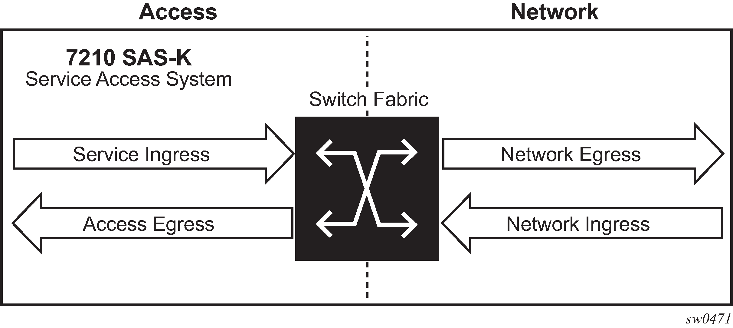
The 7210 SAS uses QoS policies applied to a SAP for a service or to an access uplink port or to a network port to define the queuing, queue attributes, meter attributes, and QoS marking/interpretation.
The 7210 SAS supports the following major types of network and service QoS policies: Network QoS policies on 7210 SAS-K 2F6C4T and 7210 SAS-K 3SFP+ 8C network ports and hybrid ports, Network QoS policies on access-uplink ports, Network queue policies, Service ingress QoS policies, and Service egress QoS policies.
The support of different policies varies across different platforms.
Network QoS policies on 7210 SAS-K 2F6C4T and 7210 SAS-K 3SFP+ 8C network ports and hybrid ports
Network QoS policies define egress QoS marking and ingress QoS interpretation for traffic received on network ports and hybrid ports.
A network QoS policy defines both the ingress and egress handling of QoS on the network ports and hybrid ports. The following functions are defined:
ingress
option to use MPLS EXP value to map traffic to available FCs and profile state
option to use dot1p value to map traffic to available FCs and profile state
option to use IP DSCP value to map traffic to available FCs and profile state
option to use all of three above simultaneously along with DEI for FC determination and assigning profile
defines FC-to-queue mapping
egress
option to define the FC and profile state to MPLS EXP value markings
option to define the FC and profile state to dot1p value markings
option to define the FC and profile state to IP DSCP value marking
remarking of QoS bits can be enabled or disabled
The required network QoS policy definitions are the following:
a unique network QoS policy ID
egress FC to priority bits (for example, 802.1p, and so on) used for marking, for each FC
a default ingress FC and an optional in-profile/out-of-profile state
at least one default unicast FC meter or queue based on the platform. See Meter/policers and policer parameters for information about the parameters that can be configured for a meter
The optional network QoS policy element definitions are the following:
additional queues
MPLS EXP value to FC and profile state mappings for all values received
dot1p value to FC and profile state mappings for all values received
option to use DEI bit along with dot1p classification for profile state mapping
option to use IP DSCP value to FC and profile state mappings for all DSCP values received
Ingress classification support for network ports and hybrid ports on 7210 SAS-K 2F6C4T and 7210 SAS-K 3SFP+ 8C
On ingress of network and hybrid ports, the user has an option to use both MPLS EXP and dot1p bits to map received MPLS packets to an FC. If both MPLS EXP and dot1p bits are configured, then the match order for MPLS packets is to match with MPLS EXP entries first and assign an FC if there is match. If no match exists, MPLS packets are matched with configured dot1p entries and assigned an FC if there is a match. If there is no match with both MPLS EXP and dot1p entries, the default configured FC is assigned. The DEI bit can be used to assign profile state to the MPLS packets on network ingress.
On ingress of network and hybrid ports, the user has an option to use both IP DSCP and dot1p bits to map received IP packets (plain routed packets in the context of network IP interfaces configured on the network port or hybrid port) to FC. If both IP DSCP and dot1p bits are configured, then the match order for IP packets is to match with IP DSCP entries first and dot1p entries next. The FC and profile value configured in the entry that matches first is assigned to the packet. If there is no match with either IP DSCP or dot1p values, the default FC is assigned to the packet. The DEI bit can be used to assign a profile state to the IP packets on network ingress.
MPLS EXP classification entries that map MPLS EXP values to FC, dot1p classification entries that map dot1p bits to FC, and IP DSCP classification entries that map IP DSCP values to FC are defined using MPLS EXP classification policies, dot1p classification policies, and DSCP classification policies, respectively.
Egress marking support for network ports and hybrid ports on 7210 SAS-K 2F6C4T and 7210 SAS-K 3SFP+ 8C
On network port and hybrid port egress, the option to mark MPLS EXP and dot1p values for MPLS packets is provided. For IP packets sent out of network IP interfaces configured on a network port or hybrid port, the option to mark IP DSCP and dot1p values for IP packets is provided. Along with dot1p, the user has an option to mark the DEI bit for both MPLS and IP DSCP packets.
Network policy ID 2 is reserved for the default network QoS policy applied to network and hybrid ports. The default policy cannot be deleted or changed. The default network QoS policy is applied to all network and hybrid ports that do not have another network QoS policy explicitly assigned.
The network QoS policy applied at the network egress (that is, on a network port or hybrid port) determines how or whether the profile state is marked in packets transmitted into the service core network. If the profile state is marked in the service packets, out-of-profile packets are preferentially dropped over in-profile packets at congestion points in the network.
For network egress, traffic remarking in the network QoS policy can be enabled or disabled.
The following table lists the default mapping of FC to dot1p values for egress marking.
FC-ID |
FC name |
FC label |
DiffServ name |
Egress dot1p marking |
MPLS EXP values |
IP DSCP values |
|||
|---|---|---|---|---|---|---|---|---|---|
In-profile |
Out-profile |
In-profile |
Out-profile |
In-profile |
Out-profile |
||||
7 |
Network Control |
nc |
NC2 |
111 - 7 |
111 - 7 |
7 |
7 |
NC2 |
NC2 |
6 |
High-1 |
h1 |
NC1 |
110 - 6 |
110 - 6 |
6 |
6 |
NC1 |
NC1 |
5 |
Expedited |
ef |
EF |
101 - 5 |
101 - 5 |
5 |
5 |
EF |
EF |
4 |
High-2 |
h2 |
AF4 |
100 - 4 |
100 - 4 |
4 |
4 |
AF41 |
AF41 |
3 |
Low-1 |
l1 |
AF2 |
011 - 3 |
010 - 2 |
3 |
3 |
AF21 |
AF22 |
2 |
Assured |
af |
AF1 |
011 - 3 |
010 - 2 |
2 |
2 |
AF11 |
AF12 |
1 |
Low-2 |
l2 |
CS1 |
001 - 1 |
001 - 1 |
1 |
1 |
CS1 |
CS1 |
0 |
Best Effort |
be |
BE |
000 - 0 |
000 - 0 |
0 |
0 |
BE |
BE |
For network ingress, the following figure lists the default mapping of dot1p values to FC and profile state for the default network QoS policy.
dot1p value |
FC |
Profile |
|---|---|---|
0 |
be |
Out |
1 |
l2 |
In |
2 |
af |
Out |
3 |
af |
In |
4 |
h2 |
In |
5 |
ef |
In |
6 |
h1 |
In |
7 |
nc |
In |
For network ingress, the following table lists the default mapping of mpls-lsp-exp-classification values to FC and profile state for the default network QoS policy.
MPLS EXP value |
Ingress FC |
Profile |
|---|---|---|
0 |
be |
Out |
1 |
l2 |
In |
2 |
af |
Out |
3 |
af |
In |
4 |
h2 |
In |
5 |
ef |
In |
6 |
h1 |
In |
7 |
nc |
In |
For network ingress, the following table lists the default mapping of dscp-classification values to FC and profile state for the default network QoS policy.
IP DSCP value |
Ingress FC |
Profile |
|---|---|---|
be |
be |
Out |
ef |
ef |
In |
cs1 |
l2 |
In |
nc1 |
h1 |
In |
nc2 |
nc |
In |
af11 |
af |
In |
af12 |
af |
Out |
af41 |
h2 |
In |
Network QoS policies on access-uplink ports
Network QoS policies define egress QoS marking and ingress QoS interpretation for traffic on received on access-uplink ports.
A network QoS policy defines both the ingress and egress handling of QoS on the access uplink ports. The following functions are defined:
ingress
option to use dot1p value mapping to FCs and profile
option to use IP DSCP value to map traffic to different FCs and profile
defines FC to ingress queue mapping
egress
option to define the FC and profile to dot1p value markings
option to define the FC and profile to IP DSCP value marking
remarking of QoS bits can be enabled or disabled
The required network QoS policy element definitions are the following:
a unique network QoS policy ID
egress - FC and optional profile state to priority bits (for example, 802.1p, and so on) used for marking, for each FC
a default ingress FC and an optional in-profile/out-of-profile state
at least one default unicast FC queue. The parameters that can be configured for a ingress queue are discussed below.
The optional network QoS policy element definitions are the following:
additional queues
dot1p value to FC and profile state mappings for all values received
option to use DEI bit along with dot1p classification for profile state mapping
option to use IP DSCP value to FC and profile state mappings for all DSCP values received
Ingress classification support for access-uplink ports
On ingress of access-uplink ports, users have the option to use both IP DSCP and dot1p bits to map received IP packets to FC. If both IP DSCP and dot1p bits are configured, then the match order for IP packets is to match with IP DSCP entries first and dot1p entries next. The FC and profile value configured in the entry which matches first is assigned to the packet. If there is no match with either IP DSCP and dot1p values, then the default FC is assigned to the packet. DEI bit can be used to assign profile state to the packets of network ingress.
On the 7210 SAS-K 2F6C4T and 7210 SAS-K 3SFP+ 8C, dot1p classification entries that map dot1p bits to FC and IP DSCP classification entries that map IP DSCP values to FC are defined by using dot1p-classification policies and DSCP classification policies respectively.
Network policy ID 1 is reserved for the default network QoS policy applied to access-uplink ports. The default policy cannot be deleted or changed. The default network QoS policy is applied to all access-uplink ports which do not have another network QoS policy explicitly assigned.
The network QoS policy applied at network egress (that is, on an access-uplink port) determines how or whether the profile state is marked in packets transmitted into the service core network. If the profile state is marked in the service packets, out-of-profile packets are preferentially dropped over in-profile packets at congestion points in the network.
For network egress, traffic remarking in the network QoS policy can be enabled or disabled.
For network egress, the following table lists the default mapping of dot1p values to FC and profile state for the default network QoS policy.
dot1p value |
Ingress FC |
Profile |
|---|---|---|
0 |
be |
Out |
1 |
l2 |
In |
2 |
af |
Out |
2 |
l1 |
In |
4 |
h2 |
In |
5 |
ef |
In |
6 |
h1 |
In |
7 |
nc |
In |
For network ingress, the following table lists the default mapping of dot1p values to FC and profile state for the default network QoS policy.
dot1p value |
Ingress FC |
Profile |
|---|---|---|
0 |
be |
Out |
1 |
l2 |
In |
2 |
af |
Out |
3 |
af |
In |
4 |
h2 |
In |
5 |
ef |
In |
6 |
h1 |
In |
7 |
nc |
In |
Network queue policies
Network queue policies are applied on egress of access-uplink ports on the 7210 SAS-K 2F1C2T.
On the 7210 SAS-K 2F6C4T and 7210 SAS-K 3SFP+ 8C, network queue policies are applied on egress for access-uplink ports, network ports, and hybrid ports.
The network egress aggregate shaper rate can be configured for hybrid ports on the 7210 SAS-K 2F6C4T and 7210 SAS-K 3SFP+ 8C using the nw-egr-agg-shaper-rate command. Configuring the command limits the amount of traffic sent out of network IP interfaces configured on the hybrid port.
The network queue policies can be defined with up to a maximum of eight egress queues. The user has an option to define the policies with fewer than eight egress queues.
Queue characteristics configured on a per-FC basis are the following:
committed buffer size (CBS) in Kilobytes
maximum buffer size (MBS) in Kilobytes
peak information rate (PIR) as a percentage of egress port bandwidth
committed information rate (CIR) as a percentage of egress port bandwidth
queue priority and queue weight
Network queue policies are identified with a unique policy name that conforms to the standard 7210 SAS alphanumeric naming conventions. The system default network queue policy is named ‟default” and cannot be edited or deleted. The following table describes the default network queue policy definition in access-uplink mode.
FC |
Queue |
Definition |
|---|---|---|
Network-Control (nc) |
Queue 8 |
PIR = 100% CIR = 10% MBS = 200 Kilobytes CBS = 50 Kilobytes -7210 SAS-K 2F1C2T CBS = 24 Kilobytes -7210 SAS-K 2F6C4T CBS = 24 Kilobytes -7210 SAS-K 3SFP+ 8C priority = 1 weight = 1 |
High-1 (h1) |
Queue 7 |
PIR = 100% CIR = 10% - 7210 SAS-K 2F1C2T and 7210 SAS-K 2F6C4T CIR = 5% - 7210 SAS-K 3SFP+ 8C MBS = 200 Kilobytes CBS = 50 Kilobytes -7210 SAS-K 2F1C2T CBS = 24 Kilobytes -7210 SAS-K 2F6C4T CBS = 24 Kilobytes -7210 SAS-K 3SFP+ 8C priority = 1 weight = 1 |
Expedited (ef) |
Queue 6 |
PIR = 100% CIR = 100% - 7210 SAS-K 2F1C2T and 7210 SAS-K 2F6C4T CIR = 15% - 7210 SAS-K 3SFP+ 8C MBS = 200 Kilobytes CBS = 50 Kilobytes -7210 SAS-K 2F1C2T CBS = 24 Kilobytes -7210 SAS-K 2F6C4T CBS = 24 Kilobytes -7210 SAS-K 3SFP+ 8C priority = 1 weight = 1 |
High-2 (h2) |
Queue 5 |
PIR = 100% CIR = 100% - 7210 SAS-K 2F1C2T and 7210 SAS-K 2F6C4T CIR = 15% - 7210 SAS-K 3SFP+ 8C MBS = 200 Kilobytes CBS = 50 Kilobytes -7210 SAS-K 2F1C2T CBS = 24 Kilobytes -7210 SAS-K 2F6C4T CBS = 24 Kilobytes -7210 SAS-K 3SFP+ 8C priority = 1 weight = 1 |
Low-1 (l1) |
Queue 4 |
PIR = 100% CIR = 25% - 7210 SAS-K 2F1C2T and 7210 SAS-K 2F6C4T CIR = 10% - 7210 SAS-K 3SFP+ 8C MBS = 200 Kilobytes CBS = 50 Kilobytes -7210 SAS-K 2F1C2T CBS = 24 Kilobytes -7210 SAS-K 2F6C4T CBS = 24 Kilobytes -7210 SAS-K 3SFP+ 8C priority = 1 weight = 1 |
Assured (af) |
Queue 3 |
PIR = 100% CIR = 25% - 7210 SAS-K 2F1C2T and 7210 SAS-K 2F6C4T CIR = 10% - 7210 SAS-K 3SFP+ 8C MBS = 200 Kilobytes CBS = 50 Kilobytes -7210 SAS-K 2F1C2T CBS = 24 Kilobytes -7210 SAS-K 2F6C4T CBS = 24 Kilobytes -7210 SAS-K 3SFP+ 8C priority = 1 weight = 1 |
Low-2 (l2) |
Queue 2 |
PIR = 100% CIR = 25% - 7210 SAS-K 2F1C2T and 7210 SAS-K 2F6C4T CIR = 10% - 7210 SAS-K 3SFP+ 8C MBS = 200 Kilobytes CBS = 50 Kilobytes -7210 SAS-K 2F1C2T CBS = 24 Kilobytes -7210 SAS-K 2F6C4T CBS = 24 Kilobytes -7210 SAS-K 3SFP+ 8C priority = 1 weight = 1 |
Best-Effort (be) |
Queue 1 |
PIR = 100% CIR = 0% MBS = 200 Kilobytes CBS = 50 Kilobytes -7210 SAS-K 2F1C2T CBS = 24 Kilobytes -7210 SAS-K 2F6C4T CBS = 24 Kilobytes -7210 SAS-K 3SFP+ 8C priority = 1 weight = 1 |
Service ingress QoS policies
Service ingress QoS policies define ingress service FC queues or meters and map traffic flows to FC on access SAP-ingress. A SAP can be configured on both access ports and hybrid ports. The service ingress QoS policy support for SAPs is the same for access ports and hybrid ports.
Not all 7210 SAS platforms support queues and meters on service ingress. The support varies across different platforms. See to subsequent chapters and sections for more information.
On 7210 SAS platforms, when a service ingress QoS policy is created, it always has one queue defined that cannot be deleted. The queue is used to queue all the traffic, both the unicast traffic and the multipoint traffic. These queues exist within the definition of the policy. The queues only get instantiated in hardware when the policy is applied to a SAP. Multipoint queues are instantiated only if the SAP-ingress policy defines a multipoint queue. By default, software does not allocate any multipoint queues.
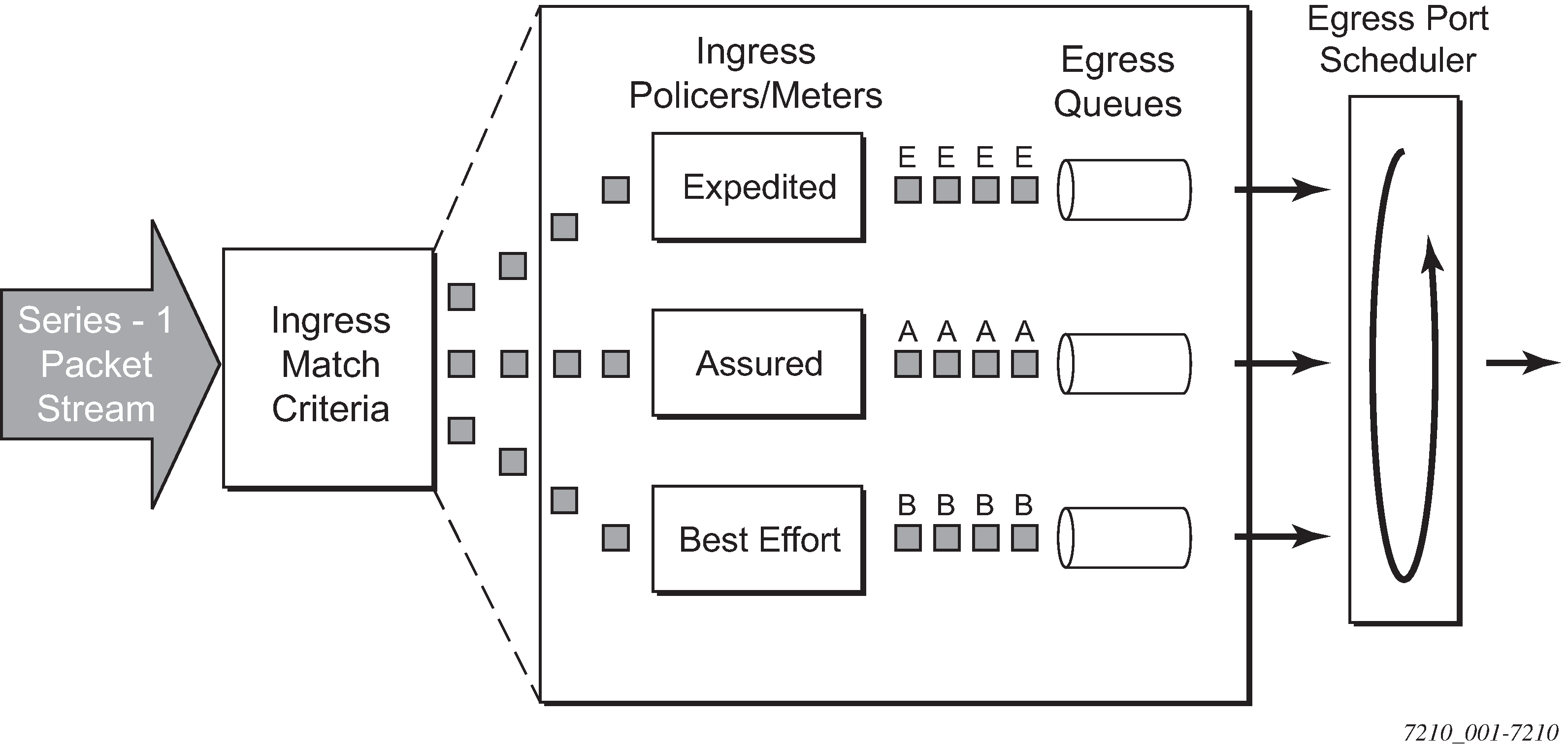
In the simplest service ingress QoS policy, all traffic is handled as a single flow and mapped to a single queue, including all flooded traffic.
The required elements to define a service ingress QoS policy are the following:
a unique service ingress QoS policy ID
a QoS policy scope of template or exclusive
at least one default FC queue. See Queues and queue parameters for more information about the parameters that can be configured for a queue.
Optional service ingress QoS policy elements for 7210 SAS platforms include the following:
additional unicast queues or multicast queues, up to eight
additional unicast meters or multicast meters, up to 16
QoS policy match criteria to map packets to an FC
Each meter or queue can have unique meter or queue parameters to allow individual shaping or rate limiting of the flow mapped to the FC. The following figure shows service traffic being classified into three different FCs.
Default service ingress policy
Service ingress QoS policy ID 1 is reserved for the default service ingress policy. The default policy cannot be deleted or changed. The default service ingress policy is implicitly applied to all SAPs that do not explicitly have another service ingress policy assigned. In the default policy, all traffic is mapped to the default FC which uses a queue by default. The following table lists the characteristics of the default policy.
Characteristic |
Item |
Definition |
|---|---|---|
Queue |
Queue 1 |
One queue defined for all unicast traffic and multicast traffic:
|
Flows |
Default FC (be) |
One flow defined for all traffic:
|
Service ingress classification
Mapping flows to FCs is controlled by comparing each packet to the match criteria in the Service Ingress QoS policy applied to an access SAP. The ingress packet classification to FC is subject to a classification policy provisioned.
Service ingress classification
On access SAP-ingress, the user has an option to use either dot1p classification, IPv4 DSCP classification, IPv4 packet header fields, IPv6 packet header fields, or MAC packet header fields. The dot1p or DSCP classification rules to be used are defined in the dot1p and DSCP classification policy and associated with the SAP-ingress policy. The DSCP and dot1p classification policies can be configured in the same QoS policy. The IPv4 or IPv6 or MAC criteria can be configured in the SAP-ingress policy.
When packets are received on an access SAP, the following steps are used to determine the FC to assign to the packet.
Match IP criteria entries with the IP packet header fields in the packet. Assign the FC corresponding to the first entry which matches with IP packet header field values in the packet. If it is not an IP packet or if there is no match, go to next step.
Match MAC criteria entries with the MAC packet header fields in the packet. Assign the FC corresponding to the first entry which matches with MAC packet header field values in the packet. If there is no match, go to next step.
Match the IP DSCP value in the packet with the value configured in each of the IP DSCP entry defined in the DSCP classification policy. Assign the FC corresponding to the first entry which matches with IP DSCP value in the packet. If it is not an IP packet or if there is no match, go to next step.
Match the dot1p value in the packet (if available) with the value configured in each of the dot1p entry defined in the dot1p classification policy. Assign the FC corresponding to the first entry which matches with dot1p value in the packet. If there is no match, go to next step.
Assign the default FC.
Service ingress classification — IP and MAC packet fields
The IP and MAC match criteria can be very basic or quite detailed. IP and MAC match criteria are assembled from policy entries. An entry is identified by a unique, numerical entry ID. A single entry cannot contain more than one match value for each match criteria. Each match entry has an action which specifies the FC of packets that match the entry. The entries are evaluated in numerical order based on the entry ID from the lowest to highest ID value. The first entry that matches all match criteria has its action performed.
The following tables list the packets fields used for match-criteria used for access SAP-ingress classification.
IP criteria |
Services applicable on 7210 SAS-K 2F1C2T |
Services applicable on 7210 SAS-K 2F6C4T and 7210 SAS-K 3SFP+ 8C |
|---|---|---|
|
IP DSCP |
Access SAPs in Epipe, VPLS, IES, RVPLS services |
Access SAPs in Epipe, VPLS, IES, VPRN, RVPLS services |
|
Access SAPs in Epipe, VPLS, IES, RVPLS services |
Access SAPs in Epipe, VPLS, IES, VPRN, RVPLS services |
IPv6 criteria |
Services applicable on 7210 SAS-K 2F1C2T |
Services applicable on 7210 SAS-K 2F6C4T and 7210 SAS-K 3SFP+ 8C |
|---|---|---|
|
DSCP value, Destination IPv6 address and mask match, Destination port TCP/UDP port match, Source IPv6 address and mask match, Source port TCP/UDP port match |
Access SAPs in Epipe, VPLS, RVPLS services |
Access SAPs in Epipe, VPLS, RVPLS services |
MAC match criteria |
Services applicable on 7210 SAS-K 2F1C2T |
Services applicable on 7210 SAS-K 2F6C4T and 7210 SAS-K 3SFP+ 8C |
|---|---|---|
|
IEEE 802.1p/dot1p value/mask (for both inner and outer tag separately), Source MAC address/mask, Destination MAC address/mask, EtherType Value/Mask, outer VLAN, and inner VLAN tag value |
Access SAPs in Epipe, VPLS, RVPLS services |
Access SAPs in Epipe, VPLS, RVPLS services |
The following table lists the Packet Fields available for match in QoS classification policy and ACL policy for different SAPs.
Ingress SAP type |
Packet contents (only Ethernet–II frames) |
MAC address match |
Inner VLAN ID and dot1p match |
Outer VLAN ID and dot1p match |
Etype match |
IPv4/IPv6 criteria match |
|---|---|---|---|---|---|---|
NULL SAP |
Null tag |
Yes |
No |
No |
Yes |
Yes |
Priority tag (both VID and dot1p) |
Yes |
No |
Yes |
Yes |
Yes |
|
Single tag |
Yes |
No |
Yes |
Yes |
Yes |
|
Two tags |
Yes |
Yes |
Yes |
Yes |
Yes |
|
Three or more tags |
Yes |
Yes |
Yes |
No |
No |
|
dot1q SAP (includes dot1q explicit null SAP and dot1q Default SAP) |
Null tag |
Yes |
No |
No |
Yes |
Yes |
Priority tag (both VID and dot1p) |
Yes |
No |
Yes |
Yes |
Yes |
|
Single tag |
Yes |
No |
Yes |
Yes |
Yes |
|
Two tags |
Yes |
Yes |
Yes |
Yes |
Yes |
|
Three or more tags |
Yes |
Yes |
Yes |
No |
No |
|
dot1q SAP (includes dot1q SAP, dot1q range SAP) |
Null tag |
Invalid |
Invalid |
Invalid |
Invalid |
Invalid |
Priority tag (both VID and dot1p) |
Invalid |
Invalid |
Invalid |
Invalid |
Invalid |
|
Single tag |
Yes |
No |
Yes |
Yes |
Yes |
|
Two tags |
Yes |
Yes |
Yes |
Yes |
Yes |
|
Three or more tags |
Yes |
Yes |
Yes |
No |
No |
|
QinQ SAP - 0.* SAP (matches only null and priority tag packets) |
Null tag |
Yes |
No |
No |
Yes |
Yes |
Priority tag (both VID and dot1p) |
Yes |
No |
Yes |
Yes |
Yes |
|
Single tag |
Invalid |
Invalid |
Invalid |
Invalid |
Invalid |
|
Two tags |
Invalid |
Invalid |
Invalid |
Invalid |
Invalid |
|
Three or more tags |
Invalid |
Invalid |
Invalid |
Invalid |
Invalid |
|
QinQ SAP (*.* Default QinQ SAP) |
Null tag |
Yes |
No |
No |
Yes |
Yes |
Priority tag (both VID and dot1p) |
Yes |
No |
Yes |
Yes |
Yes |
|
Single tag |
Yes |
No |
Yes |
Yes |
Yes |
|
Two tags |
Yes |
Yes |
Yes |
Yes |
Yes |
|
Three or more tags |
Yes |
Yes |
Yes |
No |
No |
|
QinQ SAP (includes Q1.* SAP) |
Null tag |
Invalid |
Invalid |
Invalid |
Invalid |
Invalid |
Priority tag (both VID and dot1p) |
Invalid |
Invalid |
Invalid |
Invalid |
Invalid |
|
Single tag |
Yes |
No |
Yes |
Yes |
Yes |
|
Two tags |
Yes |
Yes |
Yes |
Yes |
Yes |
|
Three or more tags |
Yes |
Yes |
Yes |
No |
No |
|
QinQ SAP (includes Q1.0 SAP) |
Null tag |
Invalid |
Invalid |
Invalid |
Invalid |
Invalid |
Priority tag (both VID and dot1p) |
Invalid |
Invalid |
Invalid |
Invalid |
Invalid |
|
Single tag |
Yes |
No |
Yes |
Yes |
Yes |
|
Two tags (inner tag is a priority tag) |
Yes |
Yes |
Yes |
Yes |
Yes |
|
Two tags (inner tag is not a priority tag) |
Invalid |
Invalid |
Invalid |
Invalid |
Invalid |
|
Three or more tags |
Yes |
Yes |
Yes |
No |
No |
|
QinQ SAP (includes Q1.Q2 SAP) |
Null tag |
Invalid |
Invalid |
Invalid |
Invalid |
Invalid |
Priority tag (both VID and dot1p) |
Invalid |
Invalid |
Invalid |
Invalid |
Invalid |
|
Single tag |
Invalid |
Invalid |
Invalid |
Invalid |
Invalid |
|
Two tags (inner tag is a priority tag) |
Invalid |
Invalid |
Invalid |
Invalid |
Invalid |
|
Two tags (inner tag is not a priority tag) |
Yes |
Yes |
Yes |
Yes |
Yes |
|
Three or more tags |
Yes |
Yes |
Yes |
No |
No |
The 7210 SAS does not support configuring of the frame-type match criteria and the default frame type configured is Ethernet - II; see the following table.
Frame format |
Description |
|---|---|
802.3 |
IEEE 802.3 Ethernet frame. Only the source MAC, destination MAC and IEEE 802.1p value are compared for match criteria. |
802dot2-llc |
IEEE 802.3 Ethernet frame with an 802.2 LLC header. Only the source MAC and destination MAC address are compared for match criteria. |
802dot2-snap |
IEEE 802.2 Ethernet frame with 802.2 SNAP header. Only the source MAC and destination MAC address are compared for match criteria. |
Ethernet-II |
Ethernet type II frame where the 802.3 length field is used as an Ethernet type (Etype) value. Etype values are two byte values greater than 0x5FF (1535 decimal). |
The default frame type configured is Ethernet-II.
The following table lists the criteria that can be matched for the various MAC frame types.
Frame format |
Source MAC |
Dest MAC |
IEEE 802.1p value |
Etype value |
|---|---|---|---|---|
802.3 |
Yes |
Yes |
Yes |
No |
802dot2-llc |
Yes |
Yes |
Yes |
No |
802dot2-snap |
Yes |
Yes |
Yes |
No |
ethernet-II |
Yes |
Yes |
Yes |
Yes |
Service egress QoS policies
Service egress queues are implemented at the transition from the service core network to the service access network on access SAPs. The advantages of per-service queuing before transmission into the access network are the following:
per-service egress sub-rate capabilities
more granular, fairer scheduling per-service into the access network
per-service statistics for forwarded and discarded service packets
The sub-rate capabilities and per-service scheduling control are required to make multiple services per physical port possible. With egress shaping, it is possible to support more than one service per port. It prevents traffic from single service from bursting to the available port bandwidth and starving other services.
For accounting purposes, per-service statistics can be logged. When statistics from service ingress queues are compared with service egress queues, the ability to conform to per-service QoS requirements within the service core can be measured.
Service egress QoS policies define egress queues and map FC flows to queues. In the simplest service egress QoS policy, all FCs are treated like a single flow and mapped to a single queue.
Service egress QoS policies also define egress queues, shaping, scheduling, and remarking behavior for SAPs configured on hybrid ports. The QoS behavior for SAPs configured on hybrid ports is the same as for access SAPs configured on access ports.
To define a basic egress QoS policy, the following are required:
a unique service egress QoS policy ID
a QoS policy scope of template or exclusive
at least one defined default queue
Optional service egress QoS policy elements include the following:
additional queues up to a total of eight separate queues. An FC queue is shared by unicast and multipoint (BUM) traffic types mapped to that FC.
IEEE 802.1p priority value remarking based on FC
option to use IP DSCP values for marking based on FC
Each queue in a policy is associated with one of the FCs. Each queue can have individual queue parameters, allowing individual rate shaping of the FCs mapped to the queue. More complex service queuing models are supported in the router where each FC is associated with a dedicated queue. The FC per service egress packet is determined at ingress. If the packet ingressed the service on the same router, the service ingress classification rules determine the FC of the packet. If the packet is received, the FC is marked in the tunnel transport encapsulation (for example, QinQ encapsulated packet).
Default service egress policy
Service egress QoS policy ID 1 is reserved as the default service egress policy. The default policy cannot be deleted or changed. The default access egress policy is applied to all SAPs service egress policy explicitly assigned. The following table lists the characteristics of the default policy.
Characteristic |
Item |
Definition |
|---|---|---|
Queues |
Queue 1 |
One queue defined for all traffic classes:
|
Flows |
Default Action |
One flow defined for all traffic classes:
|
Meters/policers
This section provides information about meters/policers.
Meter/policers and policer parameters
This section describes the available meter parameters for meters used in service ingress policies. The terms ‟meters” and ‟policers” are used interchangeably in this document to refer to metering or policing.
Not all 7210 SAS platforms support meters for all the QoS policies. In addition, the meter parameters support available varies across different platforms. See the platform-specific QoS overview sections and the chapters following to know the support available on different platforms.
Meters are available with SAP-ingress policies associated with access SAP-ingress.
Meter ID
The meter ID is used to uniquely identify the meter/policer. The meter ID is only unique within the context of the QoS policy in which the meter is defined. It allows user to define multiple Meters with different characteristics and identify them while associating it with different FCs.
The user has the option to allocate up to eight meters and assign them a meter ID along with the option to configure the meter parameters that determine the meter characteristics.
Committed information rate
The committed information rate (CIR) for a meter is the long-term average rate at which traffic is considered conforming traffic or in-profile traffic. The higher the rate, the greater the expected throughput. The user will be able to burst above the CIR and up to the PIR for brief periods of time. The time and profile of the packet is determined based on the burst sizes. See Committed burst size and Maximum burst size.
When defining the CIR for a meter, the value specified is the administrative CIR for the meter. The 7210 SAS devices have a number of native rates in the hardware that determine the operational CIR for the meter. The user has limited control over how the administrative CIR is converted to an operational CIR if the hardware does not support the exact CIR and PIR combination specified. See Adaptation rule for meters for more information about the interpretation of the administrative CIR.
The in-profile and out-profile values assigned determine the meter behavior for the packet. See Ingress profile assignment for information.
Peak information rate
The peak information rate (PIR) defines the maximum rate at which packets are allowed to exit the meter. The PIR does not specify the maximum rate at which packets can enter the meter; this is controlled by the ability of the meter to absorb bursts and is defined by its maximum burst size (MBS).When defining the PIR for a meter, the value specified is the administrative PIR for the meter. The 7210 SAS devices have a number of rates in the hardware that determine the operational PIR for the meter. The user has limited control over how the administrative PIR is converted to an operational PIR if the hardware does not support the exact CIR and PIR combination specified. See Adaptation rule for meters for more information about the interpretation of the administrative PIR.
The in-profile and out-profile values assigned determine the meter behavior for the packet. See Ingress profile assignment for information.
Adaptation rule for meters
The adaptation rule provides the QoS provisioning system with the ability to adapt specific CIR and PIR defined administrative rates to the underlying capabilities of the hardware the queue will be created on to derive the operational rates. The administrative CIR and PIR rates are translated to actual operational rates, which are enforced by the hardware meter/policer. The rule provides a constraint when the exact rate is not available.
For the CIR and PIR parameters individually, the system will attempt to find the best operational rate depending on the defined constraint. The supported constraints are the following:
minimum
The system finds the hardware supported rate that is equal to or higher than the specified rate.
maximum
The system finds the hardware supported rate that is equal to or lesser than the specified rate.
closest
The system finds the hardware supported rate that is closest to the specified rate.
Depending on the platform on which the queue is provisioned, the actual operational CIR and PIR settings used by the queue will be dependent on the method the hardware uses to implement and represent the mechanisms that enforce the CIR and PIR rates. The adaptation rule controls the method the system uses to choose the rate step based on the administrative rates defined by the rate command.
The 7210 SAS software considers the adaptation rules and the hardware values available to determine the admin PIR/CIR rates.
To illustrate (the example that follows is only for illustration of the use of adaptation rule and the values provided below does not list the actual values supported in hardware), how the adaptation rule constraints minimum, maximum and closest are evaluated in determining the operational CIR or PIR for the 7210 SAS, assume there is a queue where the administrative CIR and PIR values are 90 Kb/s and 150 Kb/s, respectively. If the adaptation rule is minimum, the operational CIR and PIR values will be 128 Kb/s and 192 Kb/s respectively, as it is the native hardware rate greater than or equal to the administrative CIR and PIR values.
If the adaptation rule is maximum, the operational CIR and PIR values are 64 kb/s and 128 kb/s. If the adaptation rule is closest, the operational CIR and PIR values are 64 kb/s and 128 kb/s, respectively, as those are the closest matches for the administrative values that are even multiples of the 64 kb/s rate step.
Committed burst size
The committed burst size parameter specifies the maximum burst size that can be transmitted by the source at the CIR while still complying with the CIR. If the transmitted burst is lower than the CBS value, the packets are marked as in-profile by the meter to indicate that the traffic is complying with meter-configured parameters.
The operational CBS set by the system is adapted from the user-configured value by using the minimum constraint. The burst size configured by the user affects the rate step-size used by the system. The system uses the step size in a manner that both the burst-size and rate parameter constraints are met.
Maximum burst size
For Two Rate Three Color Marking (trTCM) policer using two-rate three-color marker) The maximum burst size parameter specifies the maximum burst size that can be transmitted by the source at the PIR while complying with the PIR. If the transmitted burst is lower than the MBS value, the packets are marked as out-profile by the meter to indicate that the traffic is not complying with CIR, but is complying with PIR.For Single Rate Three Color Marking (srTCM) (policer using single rate three color marker), the maximum burst size parameter specifies the maximum burst size that can be transmitted by the source while not complying with the CIR. If the transmitted burst is lower than the MBS value, the packets are marked as out-profile by the meter to indicate that the traffic is not complying with CIR. If the packet burst is higher than MBS, packets marked as red are dropped.
The operational MBS set by the system is adapted from the user-configured value by using the minimum constraint. The burst size configured by the user affects the rate step-size used by the system. The system uses the step size in a manner that both the burst-size and rate parameter constraints are met.
Meter counters
The router maintains counters for meters within the system for the purpose of granular billing and accounting.
Each meter maintains the following counters:
counter to count packets and octets forwarded in-profile
counter to count packets and octets forwarded out-of-profile
counter to count packets and octets dropped
Accounting record support available on each of the platforms is listed in the 7210 SAS-D, Dxp, K 2F1C2T, K 2F6C4T, K 3SFP+ 8C System Management Guide under the ‟Accounting Records/Logs” section.
Meter modes
The 7210 SAS supports the following meter modes:
srTCM - Single Rate Three Color Marking
trTCM - Two Rate Three Color Marking
For srTCM, the CBS and MBS Token buckets are replenished at a single rate, that is CIR; however, for trTCM CBS and MBS buckets are individually replenished at CIR and PIR rates, respectively. In trTCM1, the policing algorithm is implemented as defined in RFC 4115.
Meter platform support
For all platforms, a service meter can be provisioned on access SAP-ingress within service ingress QoS policies.
Ingress profile assignment
The meter can operate in profile mode (also called color-aware mode) and non-profile mode (also called color-blind mode). On the 7210 SAS-K 2F1C2T, 7210 SAS-K 2F6C4T, and 7210 SAS-K 3SFP+ 8C, SAP ingress meters operate in either profile mode or non-profile mode.
To enable profile mode or color-aware mode, the user must assign the initial ingress profile explicitly using the in/out profile commands, which can be performed using the classification entries or DEI. If the use-dei command is enabled, the in/out profile value assigned by the user is ignored (DEI takes priority). Nokia recommends using the default value of ‟undefined” for the ingress profile when DEI is enabled. To enable color-blind metering, the user must not assign an initial ingress profile value (and the default undefined is used). With both color-aware and color-blind metering, the final color is assigned by the meter associated with the FC, based on the configured rates. The packet within CIR is assigned a final profile value of in-profile, and a packet that exceeds CIR and is within PIR is assigned a final profile value of out-profile. Anything above PIR is dropped.
The following functionality is implemented to support color-aware and color-blind metering:
ingress profile assignment as part of ingress classification (initial profile value)
on SAP-ingress, if the operator trusts the markings in the packet received from the customer device, the user has the following options:
DEI can be used to assign the initial profile value; use of DEI is enabled per FC.
Packet priority fields (for example, dot1p, IP DSCP, and so on) can be used for classification to an FC.
Packet priority fields (for example, dot1p, IP DSCP, and so on) can be used for classification to an FC and to assign the profile.
Profile is assigned using DEI overrides and initial profile value is assigned using explicit classification rules; however, Nokia recommends that you do not assign a profile explicitly when DEI use is enabled.
on SAP-ingress, if the packet header priority value is not trusted, the user has the following options:
Packet fields (for example, mac-criteria and ip-criteria) can be used for classification to an FC and to assign the profile.
If no classification entry matches or if the matched classification entry does not explicitly assign the profile, these packets are assigned a value of undefined.
ingress profile assignment as part of ingress policing or metering (lets call this the final profile value). The user has the following options:
If the initial profile value is assigned to a packet and if it is in-profile, it attempts to take tokens from CBS bucket. If available, its final profile value is set to in-profile. If not enough tokens are in the CBS bucket, check the MBS bucket. If sufficient tokens are available in the MBS bucket, the packet’s final profile value is set to out-profile. If there are not enough tokens available in the MBS bucket, it is dropped; this is the color-aware mode of operation for in-profile packets.
If the initial profile value is assigned to a packet and if it is out-profile, it attempts to take tokens from the MBS bucket. If available, its final profile value is set to out-profile. If there are not enough tokens in the MBS bucket, it is dropped; this is the color-aware mode of operation for out-profile packets.
If the initial profile value is assigned to a packet and if it is undefined, it attempts to take tokens from the CBS bucket. If available, its final profile value is set to in-profile. If not available, check for enough tokens in the MBS bucket and if available its final profile is set to out-profile. If there are not enough tokens in the MBS bucket, it is dropped; this is the color-blind mode of operation.
QoS override
The QoS Override feature support on access SAPs allows the user to override the meter parameters such as CBS, MBS, Rate (CIR and PIR), Mode, and Adaptation rule (CIR and PIR) at the SAP context.
The values are taken from the SAP-Ingress policy, when the meter parameter values are not overridden.
The configuration guidelines of QoS Override are:
QoS override commands can be used only for the meters or policers defined in the SAP-ingress policy used with access SAPs.
QoS override commands are not allowed when the attached policy is of an exclusive type.
QoS override commands are not allowed on mirror destination SAPs.
QoS override commands are not supported for service egress QoS policies used with access SAPs.
QoS override commands are not supported for ingress and egress QoS policies used with access-uplink ports.
QoS override commands are not supported ingress and egress QoS policies used with network ports.
Configuring meter override parameters
The following is a sample meter override parameter configuration output.
*A:dut-h>config>service>epipe>sap>ingress>meter-override>meter$ info detail
----------------------------------------------
                            mode trtcm2
                            adaptation-rule cir min pir max
                            cbs 1000 kbits
                            mbs 2000 kbits
                            rate cir 1000 pir 10000
----------------------------------------------
FCs
The 7210 SAS supports multiple FCs and class-based queuing, so the concept of FCs is common to all of the QoS policies. Each FC (also called Class of Service (CoS)) is important only in relation to the other FCs. A FC provides network elements a method to weigh the relative importance of one packet over another in a different FC.
Queues are created for a specific FC to determine the manner in which the queue output is scheduled. The FC of the packet, along with the in-profile or out-of-profile state, determines how the packet is queued and handled (the per hop behavior (PHB)) at each hop along its path to a destination egress point. FCs describes the eight FCs supported by 7210 SAS.
The following table lists the default definitions for the FCs. The FC behavior, in terms of ingress marking interpretation and egress marking, can be changed by QoS policies.
FC-ID |
FC name |
FC designation |
DiffServ name |
Notes |
|---|---|---|---|---|
7 |
Network Control |
NC |
NC2 |
Intended for network control traffic. |
6 |
High-1 |
H1 |
NC1 |
Intended for a second network control class or delay/jitter sensitive traffic. |
5 |
Expedited |
EF |
EF |
Intended for delay/jitter sensitive traffic. |
4 |
High-2 |
H2 |
AF4 |
Intended for delay/jitter sensitive traffic. |
3 |
Low-1 |
L1 |
AF2 |
Intended for assured traffic. Also is the default priority for network management traffic. |
2 |
Assured |
AF |
AF1 |
Intended for assured traffic. |
1 |
Low-2 |
L2 |
CS1 |
Intended for BE traffic. |
0 |
Best Effort |
BE |
BE |
Forwarding-class to queue ID mapping
There are eight FCs supported on the 7210 SAS. Each of these FCs is mapped to a specific queue. By mapping an FC to different queues, the differential treatment is imparted to various classes of traffic.
FC to queue ID mapping
The user has the option to define up to eight queues with an option to define the FC to queue mapping in service ingress policy, service egress policy, network qos policy and network queue policy.
Schedulers
The 7210 SAS supports Strict Priority and WFQ mode of scheduling or a mix of both.
On the 7210 SAS-K 2F1C2T, schedulers are used at SAP-ingress, SAP-egress, access-uplink port ingress and access-uplink port egress.
On the 7210 SAS-K 2F6C4T and 7210 SAS-K 3SFP+ 8C, schedulers are used at SAP-ingress, SAP-egress, network port ingress, network port egress, hybrid port ingress, hybrid port egress, access-uplink port ingress, and access-uplink port egress.
The scheduler uses 2 loops: the CIR loop and PIR loop, each with 4 priorities. The configured priority of the queue determines the service order of the queue in the CIR loop and the PIR loop. The scheduler first goes through the CIR loop, where it services all the queues which are operating at less than CIR rate according to their priority (that is, higher priority queues get services earlier than lower priority queues). It then goes through the PIR loop, where it services all the queues which are operating above the CIR rate (but less than PIR rate) according to their priority (that is, higher priority queues get services earlier than lower priority queues).
If there are multiple queues configured with the same priority, in the CIR loop the queues are scheduled using WFQ, with the configured weight (that is, pir-weight) of the queue used to determine the proportion of the available bandwidth that is provided to the queue. In the PIR loop, the queues are scheduled using WFQ, with the configured weight (that is, pir-weight) of the queue used to determine the proportion of the available bandwidth that is provided to the queue (using WFQ).
CPU queues
The packets that are destined for the CPU are prioritized based on the application. Some of the applications that are prioritized are Layer 2 data packets (a copy of which is sent to CPU for MAC learning), EFM, CFM, STP, LACP, and ICMP. The packets destined for the CPU are classified internally and are put into the correct CPU queue. These packets are rate-limited to prevent DoS attacks. The software programs the classification entries to identify these packets and assigns appropriate bandwidth and priority to them. It is not configurable by the user.
Egress port rate limiting
This feature allows the user to limit the bandwidth available on the egress of the port to a value less than the maximum possible link bandwidth. On some platforms, it also allows the user to control the amount of burst sent out.
Queue management
This section provides information about QoS queue management.
Queues and queue parameters
This section describes the queue parameters provisioned for queues used in service ingress policy, service egress policy, access egress policy, network qos policy and network queue policy.
Not all 7210 SAS platforms support queues for all the above policies. In addition, the queue parameters support available varies across different platforms. See platform specific QoS overview sections above and the chapter following to know the support available on different platforms.
Queues are available on different platforms.
On the 7210 SAS-K 2F1C2T, queues are available with the following:
-
SAP-ingress policies associated with access SAP-ingress
-
SAP-egress policies associated with access SAP-egress
-
Network queue policies associated with access-uplink port egress
-
Network QoS policies associated with access-uplink port ingress
On the 7210 SAS-K 2F6C4T and 7210 SAS-K 3SFP+ 8C, queues are available with the following:
-
SAP-ingress policies associated with access SAP-ingress
-
SAP-egress policies associated with access SAP-egress
-
Network queue policies associated with access-uplink port egress
-
Network QoS policies associated with access-uplink port ingress
-
Network queue policies associated with network port and hybrid port egress
-
Network QoS policies associated with network port and hybrid port ingress
Queue ID
The queue ID is used to uniquely identify the queue. The queue ID is only unique within the context of the QoS policy within which the queue is defined. It allows user to define multiple queues with different characteristics and identify them while associating it with different FCs.
The user has an option to allocate up to 8 queues and assign them a queue ID along with the option to configure some of the queue parameters that determine the queue characteristics.
Committed information rate
The committed information rate (CIR) for a queue performs two distinct functions:
Minimum bandwidth guarantees
Queue’s CIR setting provides the bandwidth that is provided to this queue as compared to other queues on the port competing for a share of the available link bandwidth. The queue CIR does not necessarily guarantee bandwidth in all scenarios and also depends on factors such as CIR over subscription and link port bandwidth capacity. For each packet in a queue, the CIR is checked with the current transmission rate of the queue. If the current rate is at or below the CIR threshold, the queue is considered in-profile. If the current rate is above the threshold, the queue is considered out-of-profile. The in-profile and out-profile state of queue is linked to scheduler prioritizing behavior as discussed below.
Scheduler queue priority metric
The scheduler serving a group of queues prioritizes individual queues based on their current CIR and PIR states. Queues operating below their CIR are always served before those queues operating at or above their CIR. Also see information about schedulers to know the scheduler behavior on different 7210 SAS platforms.
The in-profile and out-profile state of the ingress queue determines the packet’s final profile state based on the queue CIR, PIR values. The in-profile and out-profile state of the ingress queue also interacts with the scheduler mechanism and provides the minimum and maximum bandwidth guarantees. This is true only for ingress queues and not for egress queues. That is, the in-profile and out-profile state of the egress queue does not change the packets final profile state based on the queue CIR, PIR values. The in-profile and out-profile state of the egress queue only interacts with the scheduler mechanism and provides the minimum and maximum bandwidth guarantees. See Ingress profile assignment for more information.
When defining the CIR for a queue, the value specified is the administrative CIR for the queue. User has some control over how the administrative CIR is converted to an operational CIR should the hardware not support the exact CIR and PIR combination specified. The interpretation of the administrative CIR is discussed below in Adaptation rule for queues.
Although the 7210 SAS is flexible in how the CIR can be configured, there are conventional ranges for the CIR based on the FC of a queue. An egress queue associated with the high-priority class normally has the CIR threshold equal to the PIR rate although the 7210 SAS allows the CIR to be provisioned to any rate below the PIR should this behavior be required.
The CIR of the queue is configurable under the different QoS policies that provide the option to configure the queue parameters; for example, under service ingress and service egress queue policies, access port policies, and network queue policies.
Peak information rate
The peak information rate (PIR) defines the maximum rate at which packets are allowed to exit the queue. It does not specify the maximum rate at which packets may enter the queue; this is governed by the queue's ability to absorb bursts. The actual transmission rate of an egress queue depends on more than just its PIR. Each queue is competing for transmission bandwidth with other queues. Each queue's PIR, CIR and the relative priority and/or weight of the scheduler serving the queue, all combine to affect a queue's ability to transmit packets.
When defining the PIR for a queue, the value specified is the administrative PIR for the queue. The user has some control over how the administrative PIR is converted to an operational PIR should the hardware not support the exact CIR and PIR values specified. The interpretation of the administrative PIR is discussed in Adaptation rule for queues
The PIR of the queue is configurable under the different qos policies that provide the option to configure the queue parameters – example under service ingress and service egress queue policies, access port policies, network queue policies, and so on
Adaptation rule for queues
The adaptation rule provides the QoS provisioning system with the ability to adapt specific CIR and PIR defined administrative rates to the underlying capabilities of the hardware the queue will be created on to derive the operational rates. The administrative CIR and PIR rates are translated to actual operational rates enforced by the hardware queue. The rule provides a constraint used when the exact rate is not available.
For the CIR and PIR parameters individually, the system attempts to find the best operational rate depending on the defined constraint.
The supported constraints are:
minimum
Find the hardware supported rate that is equal to or higher than the specified rate.
maximum
Find the hardware supported rate that is equal to or lesser than the specified rate.
closest
Find the hardware supported rate that is closest to the specified rate.
Depending on the platform on which the queue is provisioned, the actual operational CIR and PIR settings used by the queue are dependent on the method the hardware uses to implement and represent the mechanisms that enforce the CIR and PIR rates. The adaptation rule controls the method the system uses to choose the rate step based on the administrative rates defined by the rate command.
The 7210 SAS software considers the adaptation rules and the hardware values available to determine the admin PIR/CIR rates.
To illustrate (the example that follows is only for illustration of the use of adaptation rule and the values provided below does not list the actual values supported in hardware), how the adaptation rule constraints minimum, maximum and closest are evaluated in determining the operational CIR or PIR for the 7210 SAS, assume there is a queue where the administrative CIR and PIR values are 90 kb/s and 150 kb/s, respectively. If the adaptation rule is minimum, the operational CIR and PIR values will be 128 kb/s and 192 kb/s respectively, as it is the native hardware rate greater than or equal to the administrative CIR and PIR values. If the adaptation rule is maximum, the operational CIR and PIR values will be 64 kb/s and 128 kb/s. If the adaptation rule is closest, the operational CIR and PIR values will be 64 kb/s and 128 kb/s, respectively, as those are the closest matches for the administrative values that are even multiples of the 64 kb/s rate step.
Committed burst size
The committed burst size (CBS) parameters specify the amount of buffers that can be drawn from the reserved buffer portion of the queue’s buffer pool. After the reserved buffers for a specific queue are used, the queue contends with other queues for additional buffer resources up to the maximum burst size.
The CBS of the queue is configurable under the different QoS policies, if supported by the platform, that provide the option to configure the queue parameters – example under service ingress and service egress queue policies, network queue policies, and so on The CBS for a queue is specified in kbytes.
The CBS for the queues is user-configurable. By default, software assigns a default value. It can be modified by the user as per their needs. The default value are specified in the command description.
Maximum burst size
The maximum burst size (MBS) parameter specifies the maximum queue depth to which a queue can grow. This parameter ensures that a customer that is massively or continuously oversubscribing the PIR of a queue does not consume all the available buffer resources. For high-priority FC service queues, the MBS can be relatively smaller than the other FC queues because the high-priority service packets are scheduled with priority over other service FCs.
The MBS of the queue is configurable under the different QoS policies, if supported by the platform, that provide the option to configure the queue parameters – example under service ingress and service egress queue policies, network queue policies, and so on The MBS for a queue is specified in kbytes.
The MBS for the queues is user-configurable. By default, software assigns a default value. It can be modified by the user as per their needs. The default values are specified in the command description.
Ingress profile assignment
Queues can operate in two modes – profile mode and non-profile mode.
On the 7210 SAS-K 2F1C2T, SAP-ingress queues and access uplink port ingress queues operate in either profile mode or non-profile mode.
On the 7210 SAS-K 2F6C4T and 7210 SAS-K 3SFP+ 8C, SAP-ingress queues, network port and hybrid port ingress queues, and access uplink port ingress queues operate in either profile mode or non-profile mode.
In profile mode, the profile defined in the policy is used to determine the WRED slope to use for ingress queuing, with ‟profile in” packets using high-slope and ‟profile out” packets using low-slope. The ingress queue shaper does not change the profile value assigned to a packet that has a user assigned profile value. That is, if a user assigns a profile value of green and the packet exceeds the CIR rate of the shaper, it is not changed to yellow. Similarly, packets assigned yellow are not changed by the shaper. The color assigned by the user is also subsequently used at the egress queuing point to determine the slope to use.
In non-profile mode, the profile is not specified by the user (and the node maps it to a value of ‟undefined”. The low WRED slope is used at the ingress queuing point, as all packets received are considered to be the same as ‟profile out”. The packet is then assigned the profile by the ingress queue shaper. It is assigned ‟in” profile value if it is within the CIR and assigned ‟out” profile value if it exceeds the CIR. It is dropped if it exceeds the PIR rate of ingress queue shaper (except for packets which are assigned a profile value of ‟undefined” on ingress and where the shaper assigns the profile based on CIR/PIR rate). The profile assigned by the ingress queue shaper is also subsequently used at the egress queuing point to determine the slope to use.
The user is provided with different options to assign the profile to the packet (for example, DEI based). It is always assigned on ingress of the packet into the node. When the profile is assigned at the ingress, it is used at subsequent queuing points in the system. That is, subsequent modules and queuing points in the system do not change the profile assigned to the packet on ingress. The profile assigned at ingress is also used to subsequently assign different marking/remarking values to in-profile and out-of-profile packets, if this meets user needs.
Weight and priority
A priority and weight can be assigned to the queue. The priority determines the service order of the queue when the scheduler schedules multiple queues configured on the same port. The queue weight determines the proportion of the available bandwidth that the scheduler allocates to a queue.
Queue counters
The router maintains counters for queues within the system for granular billing and accounting.
Each queue maintains the following counters:
counters for packets and octets accepted into the queue
counters for packets and octets rejected at the queue
counters for packets and octets transmitted in-profile
counters for packets and octets transmitted out-of-profile
The counters available vary among the 7210 SAS platform. Not all the counters are supported on all the platforms. Additionally there are restrictions on the number of counters that can be used simultaneously with a single queue. Some platforms can only count octets or packets and other can count both packets and octets. Counter (and corresponding accounting record) support available on each of the platform is listed in the 7210 SAS-D, Dxp, K 2F1C2T, K 2F6C4T, K 3SFP+ 8C System Management Guide in the Accounting Records/Logs section.
Queue platform support
The following support is available.
For all platforms
Service queue is provisioned on access SAP-ingress and access SAP-egress service queues within service ingress QoS policies and service egress QoS policies, respectively.
For all platforms
Access-uplink port ingress queues are defined within network QoS policies.
For all platforms
Access-uplink port egress queues are defined within network queue policies.
On the 7210 SAS-K 2F6C4T and 7210 SAS-K 3SFP+ 8C
Network port and hybrid port ingress queues are defined within network QoS policies.
On the 7210 SAS-K 2F6C4T and 7210 SAS-K 3SFP+ 8C
Network port and hybrid port egress queues are defined within network queue policies.
Buffer pools
Buffer pools are used to manage the packet buffer memory resources used to store packets and absorb bursts received on a queue.
The total amount of available buffers (approximately 64 Mb on the 7210 SAS-K 2F1C2T and 7210 SAS-K 2F6C4T, and approximately 512 Mb on the 7210 SAS-K 3SFP+ 8C) is divided among the five buffer pools listed below. In addition, the following buffers are reserved for system internal use (such as multicast queues):
CBS buffer pool
ingress non-ring MBS pool
egress non-ring MBS pool
ingress ring MBS pool
egress ring MBS pool
CBS buffer pool is used to allocate buffers toward CBS configured for ingress and egress queues on the node and some internal system queues.
The CBS pool allocation is as follows:
On the 7210 SAS-K 2F1C2T, the CBS pool is used to allocate buffers toward CBS configured for ingress and egress queues on access SAPs, and ingress and egress queues on access-uplink ports.
On the 7210 SAS-K 2F6C4T and 7210 SAS-K 3SFP+ 8C, the CBS pool is used to allocate buffers toward CBS configured for ingress and egress queues on access SAPs, ingress and egress queues on access-uplink ports, and ingress and egress queues on network ports and hybrid ports.
The MBS pool is divided into four pools as shown above: the ingress and egress non-ring MBS buffer pool and the ingress and egress ring MBS buffer pool. The MBS buffer pools can be over-subscribed.
The ingress and egress non-ring MBS buffer pool is used to allocate buffers toward the MBS configured for ingress queues and egress queues respectively on non-ring ports and non-ring service objects. The ingress and egress ring MBS buffer pool is used to allocate buffers toward the MBS configured for ingress queues and egress queues respectively on ring ports and ring service objects.
Ring ports and non-ring ports, and the corresponding ring and non-ring buffer pool on different platforms, are assigned as follows:
On the 7210 SAS-K 2F1C2T, the access ports are designated as non-ring ports by default; this designation cannot be changed. The ingress non-ring MBS pool is used to allocate buffers toward all ingress queues configured on access SAPs. Similarly, the egress non-ring MBS pool is used to allocate buffers toward all egress queues configured on access SAPs.
On the 7210 SAS-K 2F1C2T, all access-uplink ports are designated as ring ports and the ingress and egress ring MBS buffer pool is used to allocate buffers toward access-uplink port ingress and egress queues, respectively.
On the 7210 SAS-K 2F6C4T and 7210 SAS-K 3SFP+ 8C, the access ports are designated as non-ring ports by default; this designation cannot be changed. The ingress non-ring MBS pool is used to allocate buffers toward all ingress queues configured on access SAPs. Similarly, the egress non-ring MBS pool is used to allocate buffers toward all egress queues configured on access SAPs.
On the 7210 SAS-K 2F6C4T and 7210 SAS-K 3SFP+ 8C, all network ports and access-uplink ports are designated as ring ports by default; this designation cannot be changed. The ingress and egress ring MBS buffer pool is used to allocate buffers toward network port and access-uplink port ingress queues and network port and access-uplink port egress queues, respectively.
On the 7210 SAS-K 2F6C4T and 7210 SAS-K 3SFP+ 8C, when a hybrid port is configured, the behavior is as follows:
SAPs configured on hybrid ports are designated as non-ring service objects.
Network port IP interfaces configured on hybrid ports are designated as ring service objects.
The amount of memory allocated toward these pools is software-defined and not user-configurable. The show pools port-id system command can be used to display total amount of buffers per pool and the amount of buffers in use per pool.
For the 7210 SAS-K 2F1C2T and 7210 SAS-K 2F6C4T, the values are:
A:dut-i# show pools 1/1/1 system

===============================================================================
Pool Information
===============================================================================
Port                 : 1/1/1
Application          : System

MMU Total            : 65536 KB

MMU CBS              : 14336 KB          MMU CBS In Use     : 2240 KB

Ingress Ring         : 11776 KB          Ingress Ring In Use: 0 KB
Ingress NonRing      : 11776 KB          Ingress NonRing In*: 0 KB

Egress Ring          : 11776 KB          Egress Ring In Use : 0 KB
Egress NonRing       : 11776 KB          Egress NonRing In *: 0 KB

---------------------------- snipped ----------------------------
For the 7210 SAS-K 3SFP+ 8C, the values are:
A:dut-i# show pools 1/1/1 system

===============================================================================
Pool Information
===============================================================================
Port                 : 1/1/1
Application          : System

MMU Total            : 524288 KB

MMU CBS              : 105472 KB          MMU CBS In Use     : 2240 KB

Ingress Ring         : 102400 KB          Ingress Ring In Use: 0 KB
Ingress NonRing      : 102400 KB          Ingress NonRing In*: 0 KB

Egress Ring          : 102400 KB          Egress Ring In Use : 0 KB
Egress NonRing       : 102400 KB          Egress NonRing In *: 0 KB

---------------------------- snipped ----------------------------
Ring and non-ring buffer pool
When the 7210 SAS-K 2F1C2T is deployed in a ring environment, the access-uplink ports are typically used to connect the node to ring. Similarly, on the 7210 SAS-K 2F6C4T and 7210 SAS-K 3SFP+ 8C, users will typically use the network ports to join the node into a ring. Therefore, these ports are designated as the ring ports. These ring ports carry traffic from the head-end toward the node (that is, the 7210 SAS), dropping traffic off to user/customer locations. Simultaneously, these ring ports carry traffic from the user/customer to the head-end. That is, traffic received from the user/customer is added to the ring and sent out toward the service edge, where services are terminated. The traffic in both these directions is typically admitted into the ring after being shaped and groomed. In the upstream direction (that is, in the direction of customer to service edge) the SLA is enforced at service ingress points (that is, typically access SAPs) and the traffic is shaped and groomed, similarly in the downstream direction (that is, in the direction of service edge to customer) it is done by the service edge device or the access aggregation device. That is, the downstream traffic should typically be allowed to pass through the intermediate nodes of the ring, without contention with and prioritized over the traffic that is received from the customer and being added into the ring by the nodes on the ring.
On the 7210 SAS-K 2F1C2T, the access-uplink ports are designated as ring ports and access ports are designated as non-ring ports. Traffic going from any access-uplink to another access-uplink port is identified as ring traffic. Traffic going from an access port to any access-uplink port, or traffic going from any access-uplink port to an access port (in egress), or traffic going from an access port to another access port is identified as non-ring traffic.
On the 7210 SAS-K 2F6C4T and 7210 SAS-K 3SFP+ 8C, the network ports and access-uplink ports are designated as ring ports and access ports are designated as non-ring ports. Traffic going from any network port or access-uplink to another network port or access-uplink port is identified as ring traffic. Traffic going from an access port to any network port or access-uplink port, or traffic going from any network port or access-uplink port to an access port (in egress), or traffic going from an access port to another access port is identified as non-ring traffic.
On the 7210 SAS-K 2F6C4T and 7210 SAS-K 3SFP+ 8C, the SAPs configured on hybrid ports are designated as non-ring service objects, and network port IP interfaces are designated as ring service objects. Traffic going from any network port IP interface on a hybrid port to another network port IP interface on a network port or a hybrid port, or the other way around, is identified as ring traffic. Traffic going from a SAP configured on a hybrid port to any network port, access-uplink port, or access port, or to another SAP on the hybrid port, or the other way around, is designated as non-ring traffic.
To ensure that the traffic received on ring ports is prioritized over traffic received on non-ring access ports, a separate ring MBS buffer pool (one each for ingress and egress) is provided for traffic received and sent out of ring ports. In addition, for ring ports and service objects, such as network port egress, hybrid port egress, and access-uplink egress (where shaped customer (access) traffic and ring traffic share the ring pool), two additional ring slopes (for a total of four configurable WRED slopes) are provided to prioritize the ring traffic. Each egress queue on the network port, hybrid port, or access-uplink port supports four slopes per queue — ring high-slope, ring low-slope, non-ring high-slope, and non-ring low-slope (in the CLI command, the ring slopes are configured using the high-slope-ring and low-slope-ring, and the non-ring slopes are configured using the high-slope and low-slope). Ring high-slope and ring low-slope are used for in-profile and out-of-profile QoS profile ring traffic. Non-ring high-slope and low-slope are used for in-profile and out-of-profile non-ring traffic. Slope parameters (start-avg, max-avg, max-prob) of four slopes can be configured such that the ring traffic is prioritized over the non-ring traffic (that is, traffic being added onto the ring) in congestion scenarios.
A separate non-ring MBS buffer pool for traffic received and sent out of access ports along with two configurable WRED slopes is supported. Each queue on the access ports supports two slopes per queue –non-ring high-slope and non-ring low-slope. Non-ring high-slope and low-slope is used for in-profile and out-of-profile non-ring traffic. The non-ring buffer pool (one each for ingress and egress) is used to allocate buffers for non-ring traffic.
The usage of buffer pools for different traffic flows is as follows.
On the 7210 SAS-K 2F1C2T, the ring and non-ring buffer pools are used by the following traffic flows:
Traffic received on access-uplink SAP and sent out of access-uplink SAP, uses the ring MBS buffer pool for MBS buffers on access-uplink port ingress and access-uplink port egress. In this case, ring high-slope is used for in-profile traffic and ring low-slope is used for out-of-profile traffic for both access-uplink ingress and access-uplink egress.
Traffic received on access SAP and sent out of access-uplink SAP, uses the non-ring MBS buffer pool for MBS buffers on access SAP-ingress and uses the ring MBS buffer pool for MBS buffers on access-uplink SAP-egress. In this case, non-ring high slope and non-ring low slope is used on both access SAP-ingress and access-uplink egress.
Traffic received on access-uplink SAP and sent out of another access SAP uses ring MBS buffer pool for MBS buffers on access-uplink SAP-ingress and the non-ring MBS buffer pool for MBS buffers on access SAP-egress. In this case, ring high-slope and ring low-slope is used on access-uplink ingress and non-ring high-slope and non-ring low-slope is used on access egress.
Traffic received on access SAP and sent out of another access SAP uses the non-ring MBS pool for MBS buffers for both access SAP-ingress and access SAP-egress. In this case, non-ring high-slope and non-ring low-slope is used on both access ingress and access egress.
On the 7210 SAS-K 2F6C4T and 7210 SAS-K 3SFP+ 8C, the ring and non-ring buffer pools are used by the following traffic flows:
Traffic received on network port and sent out of network port, uses the ring MBS buffer pool for MBS buffers on network port ingress and network port egress. In this case, ring high-slope is used for in-profile traffic and ring low-slope is used for out-of-profile traffic for both network port ingress and port egress.
Traffic received on access SAP and sent out of port, uses the non-ring MBS buffer pool for MBS buffers on access SAP-ingress and uses the ring MBS buffer pool for MBS buffers on network port egress. In this case, non-ring high slope and non-ring low slope is used on both access SAP-ingress and network port egress.
Traffic received on network port and sent out of another access SAP uses ring MBS buffer pool for MBS buffers on network port ingress and the non-ring MBS buffer pool for MBS buffers on access SAP-egress. In this case, ring high-slope and ring low-slope is used on network port ingress and non-ring high-slope and non-ring low-slope is used on access egress.
Traffic received on access-uplink SAP and sent out of access-uplink SAP, uses the ring MBS buffer pool for MBS buffers on access-uplink port ingress and access-uplink port egress. In this case, ring high-slope is used for in-profile traffic and ring low-slope is used for out-of-profile traffic for both access-uplink ingress and access-uplink egress.
Traffic received on access SAP and sent out of access-uplink SAP, uses the non-ring MBS buffer pool for MBS buffers on access SAP-ingress and uses the ring MBS buffer pool for MBS buffers on access-uplink SAP-egress. In this case, non-ring high slope and non-ring low slope is used on both access ingress and access-uplink egress.
Traffic received on access-uplink SAP and sent out of another access SAP uses ring MBS buffer pool for MBS buffers on access-uplink SAP-ingress and the non-ring MBS buffer pool for MBS buffers on access SAP-egress. In this case, ring high-slope and ring low-slope is used on access-uplink ingress and non-ring high-slope and non-ring low-slope is used on access egress.
Traffic received on access SAP and sent out of another access SAP uses the non-ring MBS pool for MBS buffers for both access SAP-ingress and access SAP-egress. In this case, non-ring high-slope and non-ring low-slope is used on both access ingress and access egress.
Traffic received on a network IP interface on a hybrid port and sent out of a network port or another IP interface on a hybrid port uses the ring MBS buffer pool for MBS buffers on network or hybrid port ingress and network or hybrid port egress. In this case, ring high-slope is used for in-profile traffic, and ring low-slope is used for out-of-profile traffic for both network and hybrid port ingress and egress.
Traffic received on a SAP on a hybrid port and sent out of a network port or network IP interface on a hybrid port uses the non-ring MBS buffer pool for MBS buffers on SAP-ingress and the ring MBS buffer pool for MBS buffers on network port egress. In this case, non-ring high-slope and non-ring low-slope are used on both access SAP-ingress and network port egress.
Traffic received on a network IP interface on a hybrid port and sent out of a SAP configured on a hybrid port uses the ring MBS buffer pool for MBS buffers on network port ingress and the non-ring MBS buffer pool for MBS buffers on SAP-egress. In this case, ring high-slope and ring low-slope are used on network port ingress and non-ring high-slope and non-ring low-slope are used on SAP-egress.
Traffic received on a SAP on a hybrid port and sent out of an access-uplink SAP uses the non-ring MBS buffer pool for MBS buffers on SAP-ingress and uses the ring MBS buffer pool for MBS buffers on access-uplink SAP-egress. In this case, non-ring high-slope and non-ring low-slope are used on both SAP-ingress and access-uplink egress.
Traffic received on an access-uplink SAP and sent out of a SAP on a hybrid port uses the ring MBS buffer pool for MBS buffers on access-uplink SAP-ingress and the non-ring MBS buffer pool for MBS buffers on SAP-egress. In this case, ring high-slope and ring low-slope are used on access-uplink ingress and non-ring high-slope and non-ring low-slope are used on SAP-egress.
Traffic received on a SAP on a hybrid port and sent out of another SAP on the hybrid port uses the non-ring MBS pool for MBS buffers for both SAP-ingress and access SAP-egress. In this case, non-ring high-slope and non-ring low-slope are used on both SAP-ingress and SAP-egress.
Configuration guidelines for CBS and MBS
For configuring the CBS value, the following must be considered:
If Jumbo frames need to be accommodated, then CBS must be set to at least a minimum of 10 kbytes. The default value set for the queue allows for jumbo frames. It is recommended to set the CBS to twice the amount of maximum frame size the queues is expected to carry.
CBS pool cannot be oversubscribed.
For configuring the MBS value, the following must be considered:
MBS value determines the maximum delay a packet can experience when using that queue. It should be set to a value such that the delay is acceptable.
It is recommended to set the minimum value for MBS to be about four to five times the maximum size of the frame the queue is expected to carry to ensure better scheduling performance.
Slope policies
The available buffer space is partitioned into buffer pools as described in Buffer pools. The buffers for a queue are allocated from the buffer pool. Slope policies define the RED slope characteristics.
By default, each queue on the port is associated with slope-policy default which disables the high-slope and low-slope for all the queues.
If WRED is not configured, then taildrop is used.
RED slopes
This section provides information about the operation and configuration of RED slopes.
Operation and configuration of RED slopes
Each queue provides the following options:
an option to use two slopes per queue on non-ring ports - a high-priority RED slope and a low-priority RED slope
an option to use four slopes per queue on ring ports – a non-ring high-priority RED slope, a non-ring low-priority RED slope, a ring high-priority RED slope, and a ring low-priority RED slope
The high-priority RED slope manages access to the shared portion of the buffer pool for high-priority or in-profile packets. The low-priority RED slope manages access to the shared portion of the buffer pool for low-priority or out-of-profile packets. See Buffer pools for more information.
By default, the high-priority and low-priority slopes are disabled.
When a queue depth exceeds the queue CBS, packets received on that queue must contend with other queues exceeding their CBS for shared buffers. To resolve this contention, RED slopes are used to determine buffer availability on a packet-by- packet basis. A packet that is either classified as high-priority or considered in-profile is handled by the high-priority RED slope. This slope should be configured with RED parameters that prioritize buffer availability over packets associated with the low-priority RED slope. Packets that are classified as low priority or out-of-profile are handled by this low-priority RED slope.
Simplified overview of RED
The following is a simplified overview of how a RED slope determines shared buffer availability on a packet basis:
The RED function keeps track of shared buffer utilization and shared buffer average utilization.
At initialization, the utilization is zero and the average utilization is zero.
When each packet is received, the current average utilization is plotted on the slope to determine the packet discard probability.
A random number is generated associated with the packet and is compared to the discard probability.
The lower the discard probability, the lower the chances that the random number is within the discard range.
If the random number is within the range, the packet is discarded, which results in no change to the utilization or average utilization of the shared buffers.
A packet is discarded if the utilization variable is equal to the shared buffer size, or if the utilized CBS (actually in use by queues, not just defined by the CBS) is oversubscribed and has stolen buffers from the shared size, lowering the effective shared buffer size equal to the shared buffer utilization size.
The new shared buffer average utilization is used as the shared buffer average utilization next time a packet probability is plotted on the RED slope.
When a packet is removed from a queue (if the buffers returned to the buffer pool are from the shared buffers), the shared buffer utilization is reduced by the amount of buffers returned. If the buffers are from the CBS portion of the queue, the returned buffers do not result in a change in the shared buffer utilization.
The following figure shows how a RED slope is a graph with an X (horizontal) and Y (vertical) axis. The X-axis plots the percentage of shared buffer average utilization, ranging from 0 to 100 %. The Y-axis plots the probability of packet discard marked as 0 to 1. The actual slope can be defined as four sections in (X, Y) points.
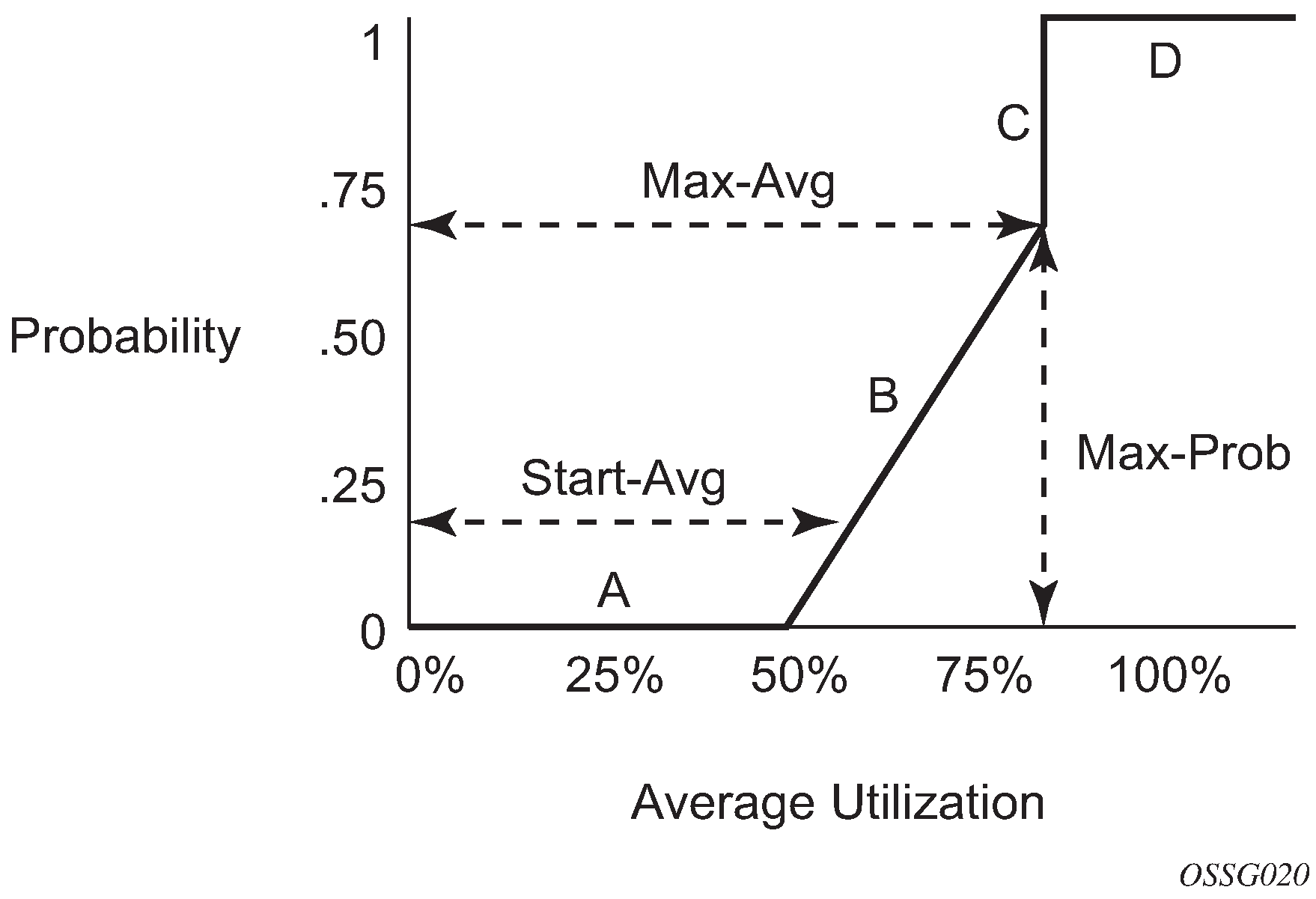
The following describes the sections shown in the preceding figure:
Section A is (0, 0) to (start-avg, 0). This is the part of the slope where the packet discard value is always zero, preventing the RED function from discarding packets when the shared buffer average utilization falls between 0 and start-avg.
Section B is (start-avg, 0) to (max-avg, max-prob). This part of the slope describes a linear slope where packet discard probability increases from zero to max-prob.
Section C is (max-avg, max-prob) to (max-avg, 1). This part of the slope describes the instantaneous increase of packet discard probability from max-prob to one. A packet discard probability of 1 results in an automatic discard of the packet.
Section D is (max-avg, 1) to (100%, 1). On this part of the slope, the shared buffer average utilization value of max-avg to 100% results in a packet discard probability of 1.
Plotting any value of shared buffer average utilization results in a value for packet discard probability from 0 to 1. Changing the values for start-avg, max-avg, and max-prob allows the adaptation of the RED slope to the needs of the different queues (for example, access port queues) using the shared portion of the buffer pool, including disabling the RED slope.
Slope policy parameters
The elements required to define a slope policy are:
a unique policy ID
the high-slope (for in-profile packets) and low-slope (for out-of-profile packets) per queue; configurable parameters on each slope are start-avg, max-avg, and max-prob
the ring and non-ring high and low slopes for access-uplink port egress
on the 7210 SAS-K 2F6C4T and 7210 SAS-K 3SFP+ 8C, the ring and non-ring high and low slopes for network port and hybrid port egress
The following table lists the default slope policy definitions.
Parameter |
Description |
|---|---|
high-slope |
start-avg 70 Percent max-avg 90 Percent max-prob 80 Percent |
low-slope |
start-avg 50 Percent max-avg 75 Percent max-prob 80 Percent |
high-slope-ring |
start-avg 70 Percent max-avg 90 Percent max-prob 80 Percent |
low-slope-ring |
start-avg 50 Percent max-avg 75 Percent max-prob 80 Percent |
Preclassification on 7210 SAS-K 2F6C4T and 7210 SAS-K 3SFP+ 8C
On the 7210 SAS-K 2F6C4T and 7210 SAS-K 3SFP+ 8C, the front-panel ports oversubscribe the capacity of the forwarding processor, with the exception of ports 1/1/1 and 1/1/2 on the 7210 SAS-K 3SFP+ 8C, which are not oversubscribed. A system-defined preclassification scheme is implemented (it is not user-configurable) to prioritize ingress packets for processing by the forwarding processor. It prioritizes packets based on dot1p and DSCP and identifies some of the untagged Layer 2 control protocols into high-priority and low-priority queues maintained on ingress per port. The forwarding processor processes the high-priority queue across all the ports before servicing packets from the lower-priority queues. In addition, the network ports are favored over access ports by allocating more weight to the network ports during scheduling.
QoS policy entities
Services are configured using default QoS policies. Additional policies must be explicitly created and associated. For 7210 SAS-K platforms, the following policies are configured by default:
one default service ingress QoS policy
one default service egress QoS policy
two default network ingress QoS policies (Network 1 and Network 2)
one default network queue policy
Only one ingress QoS policy and one egress QoS policy can be applied to a SAP, access-uplink port, network port, or hybrid port.
When you create a new QoS policy, default values are provided for most parameters with the exception of the policy ID and descriptions. Each policy has a scope, default action, description, and meters for ingress policies and queues for egress policies. By default, all FCs are mapped to Queue 1.
QoS policies can be applied to the following service types.
Epipe and VPLS:
-
On the 7210 SAS-K 2F1C2T, SAP-ingress policies and SAP-egress policies are supported on an Epipe access service access point (SAP), VPLS access SAP, RVPLS SAP, and IES SAP.
-
On the 7210 SAS-K 2F6C4T and 7210 SAS-K 3SFP+ 8C, SAP-ingress policies and SAP-egress policies are supported on an Epipe service access point (SAP), VPLS access SAP, RVPLS SAP, IES access SAP, and VPRN access SAP.
QoS policies can be applied to the following entities:
network QoS policy on access uplink port (all platforms)
network queue policy (egress) on access uplink port (all platforms)
network QoS policy on network port and hybrid port in network mode (7210 SAS-K 2F6C4T and 7210 SAS-K 3SFP+ 8C only)
network queue policy (egress) on network port and hybrid port in network mode (7210 SAS-K 2F6C4T and 7210 SAS-K 3SFP+ 8C only)
Summary of QoS policy support for hybrid ports on 7210 SAS-K 2F6C4T and 7210 SAS-K 3SFP+ 8C
The following list describes an overview of QoS policy support on hybrid ports:
Network queue policies are supported for queue configuration of egress queues on hybrid ports.
Network QoS policies are supported for hybrid ports. The behavior is similar to the behavior for network ports, supporting per-port ingress classification and queuing and egress marking.
SAP-ingress QoS policies are supported for SAPs configured on hybrid ports. The behavior is similar to the behavior for SAP-ingress on access ports.
The network egress aggregate shaper rate can be configured for hybrid ports on the 7210 SAS-K 2F6C4T and 7210 SAS-K 3SFP+ 8C using the nw-egr-agg-shaper-rate command. This command limits the amount of traffic sent out of network IP interfaces configured on the hybrid port. For information about configuring the egress aggregate shaper rate, see the 7210 SAS-D, Dxp, K 2F1C2T, K 2F6C4T, K 3SFP+ 8C Interface Configuration Guide.
Configuration notes
The following information describes QoS implementation guidelines and restrictions:
Creating additional QoS policies is optional.
Default policies are created for service ingress, service egress, access service egress, network, network queue, slope, remark, dot1p and DSCP classification, and port scheduler. (the policy types created varies across the platforms)
Associating a service, access, or access uplink with a QoS policy other than the default policy is optional.