OSPF
This chapter provides information about configuring the Open Shortest Path First (OSPF) protocol.
OSPFv3 is not supported for use as a PE-CE routing protocol on any of the platforms as described in this document.
The platforms as described in this document allow for the configuration of a single instance at any time. The instance ID can be any number other than 0. This enables these platforms to be used in a network where multi-instance OSPF is deployed, and the node needs to use an instance ID other than the default instance ID of 0.
On the 7210 SAS-K 2F6C4T, scaling is designed so that the platforms can fit into an OSPF stub area or NSSA area.
Configuring OSPF
OSPF (Open Shortest Path First) is a hierarchical link state protocol. OSPF is an interior gateway protocol (IGP) used within large autonomous systems (ASs). OSPF routers exchange state, cost, and other relevant interface information with neighbors. The information exchange enables all participating routers to establish a network topology map. Each router applies the Dijkstra algorithm to calculate the shortest path to each destination in the network. The resulting OSPF forwarding table is submitted to the routing table manager to calculate the routing table.
When a router is started with OSPF configured, OSPF, along with the routing-protocol data structures, is initialized and waits for indications from lower-layer protocols that its interfaces are functional. Nokia’s implementation of OSPF conforms to OSPF Version 2 specifications presented in RFC 2328, OSPF Version 2. Routers running OSPF can be enabled with minimal configuration. All default and command parameters can be modified.
Key OSPF features are:
backbone areas
stub areas
Not-So-Stubby areas (NSSAs)
virtual links
authentication
route redistribution
routing interface parameters
OSPF-TE extensions (Nokia’s implementation allows MPLS fast reroute)
addressing semantics have been removed from OSPF packets and the basic link-state advertisements (LSAs); new LSAs have been created to carry IPv6 addresses and prefixes
OSPF3 runs on a per-link basis, instead of on a per-IP-subnet basis
unlike OSPFv2, OSPFv3 authentication relies on IPV6's authentication header and encapsulating security payload
most packets in OSPF for IPv6 are almost as compact as those in OSPF for IPv4, even with the larger IPv6 addresses
The 7210 SAS-K 2F6C4T and the 7210 SAS-K 3SFP+ 8C support IGP-LDP synchronization on OSPF routes. See the ‟IGP-LDP and Static Route-LDP Synchronization on the 7210 SAS-K 2F6C4T and 7210 SAS-K 3SFP+ 8C” in the 7210 SAS-D, Dxp, K 2F1C2T, K 2F6C4T, K 3SFP+ 8C Router Configuration Guide for more information.
OSPF areas
The hierarchical design of OSPF allows a collection of networks to be grouped into a logical area. An area’s topology is concealed from the rest of the AS which significantly reduces OSPF protocol traffic. With the proper network design and area route aggregation, the size of the route-table can be drastically reduced which results in decreased OSPF route calculation time and topological database size.
Routing in the AS takes place on two levels, depending on whether the source and destination of a packet reside in the same area (intra-area routing) or different areas (inter-area routing). In intra-area routing, the packet is routed solely on information obtained within the area; no routing information obtained from outside the area is used.
Routers that belong to more than one area are called area border routers (ABRs). An ABR maintains a separate topological database for each area it is connected to. Every router that belongs to the same area has an identical topological database for that area.
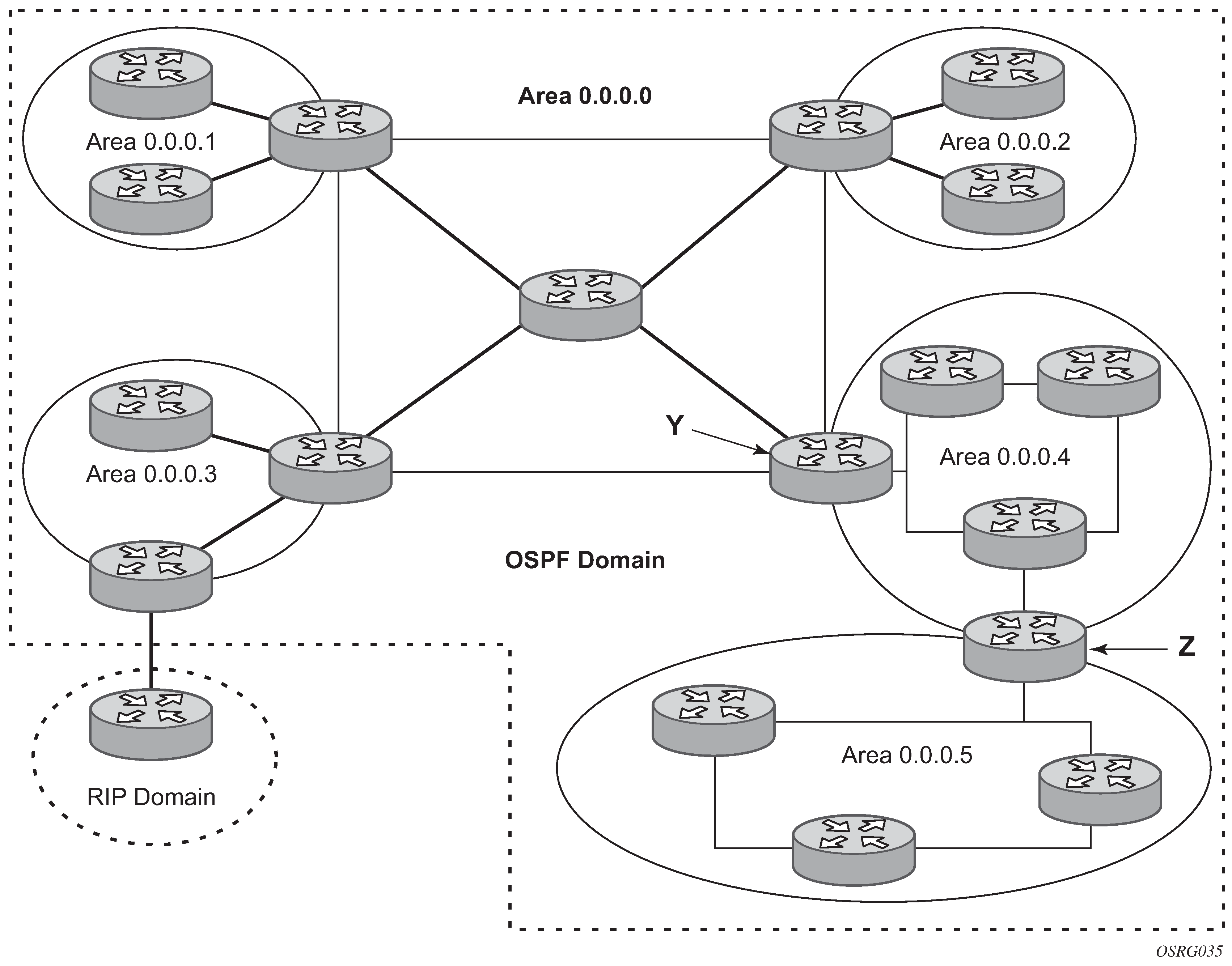
Backbone area
The OSPF backbone area, area 0.0.0.0, must be contiguous and all other areas must be connected to the backbone area. The backbone distributes routing information between areas. If it is not practical to connect an area to the backbone (see area 0.0.0.5 in the following figure), the ABRs (such as routers Y and Z) must be connected via a virtual link. The two ABRs form a point-to-point-like adjacency across the transit area (see area 0.0.0.4).
Stub area
A stub area is a designated area that does not allow external route advertisements. Routers in a stub area do not maintain external routes. A single default route to an ABR replaces all external routes. This OSPF implementation supports the optional summary route (type-3) advertisement suppression from other areas into a stub area. This feature further reduces topological database sizes and OSPF protocol traffic, memory usage, and CPU route calculation time.
In Backbone area, areas 0.0.0.1, 0.0.0.2 and 0.0.0.5 could be configured as stub areas. A stub area cannot be designated as the transit area of a virtual link and a stub area cannot contain an AS boundary router. An AS boundary router exchanges routing information with routers in other ASs.
Not-So-Stubby Area
Another OSPF area type is called a Not-So-Stubby area (NSSA). NSSAs are similar to stub areas in that no external routes are imported into the area from other OSPF areas. External routes learned by OSPF routers in the NSSA area are advertised as type-7 LSAs within the NSSA area and are translated by ABRs into type-5 external route advertisements for distribution into other areas of the OSPF domain. An NSSA area cannot be designated as the transit area of a virtual link.
In Backbone area, area 0.0.0.3 could be configured as a NSSA area.
OSPF super backbone
The 7210 SAS PE routers have implemented a version of the BGP/OSPF interaction procedures as defined in RFC 4577, OSPF as the Provider/Customer Edge Protocol for BGP/MPLS IP Virtual Private Networks (VPNs). The features included in this RFC are:
loop prevention
handling LSAs received from the CE
sham links
managing VPN-IPv4 routes received by BGP
VPRN routes can be distributed among the PE routers by BGP. If the PE uses OSPF to distribute routes to the CE router, the standard procedures governing BGP/OSPF interactions causes routes from one site to be delivered to another in type 5 LSAs, as AS-external routes.
The MPLS VPN super backbone behaves like an additional layer of hierarchy in OSPF. The PE-routers that connect the respective OSPF areas to the super backbone function as OSPF Area Border Routers (ABR) in the OSPF areas to which they are attached. To achieve full compatibility, they can also behave as AS Boundary Routers (ASBR) in non-stub areas.
The PE-routers insert inter-area routes from other areas into the area in which the CE-router is present. The CE-routers are not involved at any level nor are they aware of the super backbone or of other OSPF areas present beyond the MPLS VPN super backbone.
The CE always assumes the PE is an ABR:
If the CE is in the backbone then the CE router assumes that the PE is an ABR linking one or more areas to the backbone.
If the CE in not in the backbone, then the CE believes that the backbone is on the other side of the PE.
As such, the super backbone looks like another area to the CE.
In the following figure, the PEs are connected to the MPLS-VPN super backbone. To be able to distinguish if two OSPF instances are in fact the same and require Type 3 LSAs to be generated or are two separate routing instances where type 5 external LSAs need to be generated the concept of a domain-id is introduced.
Figure 2. PEs connected to an MPLS-VPN super backbone 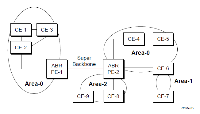
The domain ID is carried with the MP-BGP update and indicates the source OSPF Domain. When the routes are being redistributed into the same OSPF Domain, the concepts of previously described super backbone apply and Type 3 LSAs should be generated. If the OSPF domain does not match, then the route type will be external.
Configuring the super backbone (not the sham links) makes all destinations learned by PEs with matching domain IDs inter-area routes.
When configuring sham links, these links become intra-area routes if they are present in the same area.
Sham links
The following figure shows the red link between CE-3 and CE-4 could be a low speed OC-3/STM-1 link but because it establishes a intra-area route connection between the CE-3 and CE-4 the potentially high-speed PE-1 to PE-2 connection will not be utilized. Even with a super backbone configuration it is regarded as a inter-area connection.

The establishment of the (green) sham-link is also constructed as an intra-area link between PE routers, a normal OSPF adjacency is formed and the link-state database is exchanged across the MPLS-VPRN. As a result, the desired intra-area connectivity is created, at this time the cost of the green and red links can be managed such that the red link becomes a standby link only in case the VPN fails.
A sham link is only required if a back door link (shown as the red link in the preceding figure) is present; otherwise, configuring an OSPF super backbone will probably suffice.
Implementing the OSPF super backbone
With the OSPF super backbone architecture, the continuity of OSPF routing is preserved:
The OSPF intra-area LSAs (type-1 and type-2) advertised bye the CE are inserted into the MPLS-VPRN super backbone by redistributing the OSPF route into MP-BGP by the PE adjacent to the CE.
The MP-BGP route is propagated to other PE-routers and inserted as an OSPF route into other OSPF areas. Considering the PEs across the super backbone always act as ABRs they will generate inter area route OSPF summary LSAs, Type 3.
The inter-area route can now be propagated into other OSPF areas by other customer owned ABRs within the customer site.
Customer Area 0 (backbone) routes when carried across the MPLS-VPRN using MPBGP will appear as Type 3 LSAs even if the customer area remains area 0 (backbone).
A BGP extended community (OSPF domain ID) provides the source domain of the route. This domain ID is not carried by OSPF but carried by MP-BGP as an extended community attribute.
If the configured extended community value matches the receiving OSPF domain, then the OSPF super backbone is implemented.
From a BGP perspective, the cost is copied into the MED attribute.
Loop avoidance
If a route sent from a PE router to a CE router could then be received by another PE router from one of its own CE routers then it is possible for routing loops to occur. RFC 4577 specifies several methods of loop avoidance.
DN-BIT
When a Type 3 LSA is sent from a PE router to a CE router, the DN bit in the LSA options field is set. This is used to ensure that if any CE router sends this Type 3 LSA to a PE router, the PE router will not redistribute it further.
When a PE router needs to distribute to a CE router a route that comes from a site outside the latter's OSPF domain, the PE router presents itself as an ASBR (Autonomous System Border Router), and distributes the route in a type 5 LSA. The DN bit MUST be set in these LSAs to ensure that they will be ignored by any other PE routers that receive them.
DN-BIT loop avoidance is also supported.
Route tag
If a particular VRF in a PE is associated with an instance of OSPF, then by default it is configured with a special OSPF route tag value called the VPN route tag. This route tag is included in the Type 5 LSAs that the PE originates and sends to any of the attached CEs. The configuration and inclusion of the VPN Route Tag is required for backward compatibility with deployed implementations that do not set the DN bit in Type 5 LSAs.
OSPFv3 authentication
OSPFv3 authentication requires IPv6 IPSec and supports the following:
IPSec transport mode
AH and ESP
Manual keyed IPSec Security Association (SA)
Authentication Algorithms MD5 and SHA1
To pass OSPFv3 authentication, OSPFv3 peers must have matching inbound and outbound SAs configured using the same SA parameters such as SPI, keys and related parameters. The implementation must allow the use of one SA for both inbound and outbound directions.
The re-keying procedure defined in RFC 4552, Authentication/Confidentiality for OSPFv3, supports the following:
For every router on the link, create an additional inbound SA for the interface being re-keyed using a new SPI and the new key.
For every router on the link, replace the original outbound SA with one using the new SPI and key values. The SA replacement operation must be atomic with respect to sending OSPFv3 packet on the link, so that no OSPFv3 packets are sent without authentication or encryption.
For every router on the link, remove the original inbound SA.
The key rollover procedure automatically starts when the operator changes the configuration of the inbound static-SA or bidirectional static-SA under an interface or virtual link. Within the KeyRolloverInterval time period, OSPF3 accepts packets with both the previous inbound static-SA and the new inbound static-SA, and the previous outbound static-SA should continue to be used. When the timer expires, OSPF3 only accepts packets with the new inbound static-SA and for outgoing OSPF3 packets, the new outbound static-SA is used instead.
OSPFv3 graceful restart helper
This feature extends the Graceful Restart helper function supported on OSPFv2 protocols to OSPFv3:
The primary difference between graceful restart helper for OSPFv2 and OSPFv3 is in OSPFv3 a different grace-LSA format is used.
The graceful restart helper mode allows SR OS-based systems to provide a grace period to other routers which have requested it, during which the SR OS systems will continue to use routes authored by or transiting the router requesting the grace period. This is typically used when another router is rebooting the control plane but the forwarding plane is expected to continue to forward traffic based on the previously available FIB.
The grace-LSA format for OSPF restart (GRACE) LSA format is:
0                   1                   2                   3
0 1 2 3 4 5 6 7 8 9 0 1 2 3 4 5 6 7 8 9 0 1 2 3 4 5 6 7 8 9 0 1
+-+-+-+-+-+-+-+-+-+-+-+-+-+-+-+-+-+-+-+-+-+-+-+-+-+-+-+-+-+-+-+-+
|          LS age              |0|0|0|          11              |
+-+-+-+-+-+-+-+-+-+-+-+-+-+-+-+-+-+-+-+-+-+-+-+-+-+-+-+-+-+-+-+-+
|                      Link State ID                            |
+-+-+-+-+-+-+-+-+-+-+-+-+-+-+-+-+-+-+-+-+-+-+-+-+-+-+-+-+-+-+-+-+
|                     Advertising Router                        |
+-+-+-+-+-+-+-+-+-+-+-+-+-+-+-+-+-+-+-+-+-+-+-+-+-+-+-+-+-+-+-+-+
|                     LS sequence number                        |
+-+-+-+-+-+-+-+-+-+-+-+-+-+-+-+-+-+-+-+-+-+-+-+-+-+-+-+-+-+-+-+-+
|      LS checksum            |              Length             |
+-+-+-+-+-+-+-+-+-+-+-+-+-+-+-+-+-+-+-+-+-+-+-+-+-+-+-+-+-+-+-+-+
|                                                               |
+-                           TLVs                              -+
|                            ...                                |
The Link State ID of a grace-LSA in OSPFv3 is the Interface ID of the interface originating the LSA.The format of each TLV is:
0                   1                   2                   3
0 1 2 3 4 5 6 7 8 9 0 1 2 3 4 5 6 7 8 9 0 1 2 3 4 5 6 7 8 9 0 1
+-+-+-+-+-+-+-+-+-+-+-+-+-+-+-+-+-+-+-+-+-+-+-+-+-+-+-+-+-+-+-+-+
|             Type             |            Length              |
+-+-+-+-+-+-+-+-+-+-+-+-+-+-+-+-+-+-+-+-+-+-+-+-+-+-+-+-+-+-+-+-+
|                           Value...                            |
+-+-+-+-+-+-+-+-+-+-+-+-+-+-+-+-+-+-+-+-+-+-+-+-+-+-+-+-+-+-+-+-+

                          TLV Format
Virtual links
The backbone area in an OSPF AS must be contiguous and all other areas must be connected to the backbone area. Sometimes, this is not possible. You can use virtual links to connect to the backbone through a non-backbone area.
Backbone area shows routers Y and Z as the start and end points of the virtual link while area 0.0.0.4 is the transit area. To configure virtual links, the router must be an ABR. Virtual links are identified by the router ID of the other endpoint, another ABR. These two endpoint routers must be attached to a common area, called the transit area. The area through which you configure the virtual link must have full routing information.
Transit areas pass traffic from an area adjacent to the backbone or to another area. The traffic does not originate in, nor is it destined for, the transit area. The transit area cannot be a stub area or a NSSA area.
Virtual links are part of the backbone, and behave as if they were unnumbered point-to-point networks between the two routers. A virtual link uses the intra-area routing of its transit area to forward packets. Virtual links are brought up and down through the building of the shortest-path trees for the transit area.
Neighbors and adjacencies
A router uses the OSPF Hello protocol to discover neighbors. A neighbor is a router configured with an interface to a common network. The router sends hello packets to a multicast address and receives hello packets in return.
In broadcast networks, a designated router and a backup designated router are elected. The designated router is responsible for sending link-state advertisements (LSAs) describing the network, which reduces the amount of network traffic.
The routers attempt to form adjacencies. An adjacency is a relationship formed between a router and the designated or backup designated router. For point-to-point networks, no designated or backup designated router is elected. An adjacency must be formed with the neighbor.
To significantly improve adjacency forming and network convergence, a network should be configured as point-to-point if only two routers are connected, even if the network is a broadcast media such as Ethernet.
When the link-state databases of two neighbors are synchronized, the routers are considered to be fully adjacent. When adjacencies are established, pairs of adjacent routers synchronize their topological databases. Not every neighboring router forms an adjacency. Routing protocol updates are only sent to and received from adjacencies. Routers that do not become fully adjacent remain in the two-way neighbor state.
Link-state advertisements
Link-state advertisements (LSAs) describe the state of a router or network, including router interfaces and adjacency states. Each LSA is flooded throughout an area. The collection of LSAs from all routers and networks form the protocol's topological database.
The distribution of topology database updates take place along adjacencies. A router sends LSAs to advertise its state according to the configured interval and when the router's state changes. These packets include information about the router's adjacencies, which allows detection of non-operational routers.
When a router discovers a routing table change or detects a change in the network, link state information is advertised to other routers to maintain identical routing tables. Router adjacencies are reflected in the contents of its link state advertisements. The relationship between adjacencies and the link states allow the protocol to detect non-operating routers. Link state advertisements flood the area. The flooding mechanism ensures that all routers in an area have the same topological database. The database consists of the collection of LSAs received from each router belonging to the area.
OSPF sends only the part that has changed and only when a change has taken place. From the topological database, each router constructs a tree of shortest paths with itself as root. OSPF distributes routing information between routers belonging to a single AS.
Metrics
In OSPF, all interfaces have a cost value or routing metric used in the OSPF link-state calculation. OSPF uses cost values to determine the best path to a particular destination: the lower the cost value, the more likely the interface will be used to forward data traffic.
Authentication
All OSPF protocol exchanges can be authenticated. This means that only trusted routers can participate in autonomous system routing. Nokia’s implementation of OSPF supports plain text and Message Digest 5 (MD5) authentication (also called simple password).
MD5 allows an authentication key to be configured per network. Routers in the same routing domain must be configured with the same key. When the MD5 hashing algorithm is used for authentication, MD5 is used to verify data integrity by creating a 128-bit message digest from the data input. It is unique to that data. Nokia’s implementation of MD5 allows the migration of an MD5 key by using a key ID for each unique key.
By default, authentication is not enabled on an interface.
Multiple OSPF instances
Nokia recommends using only a single instance of OSPFv2. This allows for the use of different instance IDs, if required by the customer.
Route export policies for OSPF
Route policies allow specification of the source OSPF process ID in the from and to parameters in the config>router>policy-options>policy-statement>entry>from context, for example from protocol ospf instance-id.
If an instance-id is specified, only routes installed by that instance are picked up for announcement. If no instance-id is specified, then only routes installed by the base instance is will be announced. The all keyword announces routes installed by all instances of OSPF.
When announcing internal (intra/inter-area) OSPF routes from another process, the default type should be type-1, and metric set to the route metric in RTM. For AS-external routes, by default the route type (type-1/2) should be preserved in the originated LSA, and metric set to the route metric in RTM. By default, the tag value should be preserved when an external OSPF route is announced by another process. All these can be changed with explicit action statements.
Export policy should allow a match criteria based on the OSPF route hierarchy (for example, only intra-area, only inter-area, only external, only internal (intra/inter-area)). There must also be a possibility to filter based on existing tag values.
Preventing route redistribution loops
The legacy method for this was to assign a tag value to each OSPF process and mark each external route originated within that domain with that value. However, because the tag value must be preserved throughout different OSPF domains, this only catches loops that go back to the originating domain and not where looping occurs in a remote set of domains. To prevent this type of loop, the route propagation information in the LSA must be accumulative. The following method has been implemented:
The OSPF tag field in the AS-external LSAs is treated as a bit mask, instead of a scalar value. That is, each bit in the tag value can be independently checked, set or reset as part of the routing policy.
When a set of OSPF domains are provisioned in a network, each domain is assigned a specific bit value in the 32-bit tag mask. When an external route is originated by an ASBR using an internal OSPF route in a specific domain, a corresponding bit is set in the AS-external LSA. As the route gets redistributed from one domain to another, more bits are set in the tag mask, each corresponding to the OSPF domain the route visited. Route redistribution looping is prevented by checking the corresponding bit as part of the export policy--if the bit corresponding to the announcing OSPF process is already set, the route is not exported there.
From the CLI perspective, this involves adding a set of from tag and action tag commands that allow for bit operations.
IP subnets
OSPF enables the flexible configuration of IP subnets. Each distributed OSPF route has a destination and mask. A network mask is a 32-bit number that indicates the range of IP addresses residing on a single IP network/subnet. This specification displays network masks as hexadecimal numbers; for example, the network mask for a class C IP network is displayed as 0xffffff00. Such a mask is often displayed as 255.255.255.0.
Two different subnets with same IP network number have different masks, called variable length subnets. A packet is routed to the longest or most specific match. Host routes are considered to be subnets whose masks are all ones (0xffffffff).
Preconfiguration recommendations
Before configuring OSPF, the router ID must be available. The router ID is a 32-bit number assigned to each router running OSPF. This number uniquely identifies the router within an AS. OSPF routers use the router IDs of the neighbor routers to establish adjacencies. Neighbor IDs are learned when Hello packets are received from the neighbor.
Before configuring OSPF parameters, ensure that the router ID is derived by one of the following methods:
Define the value in the config>router router-id context.
Define the system interface in the config>router>interface ip-int-name context (used if the router ID is not specified in the config>router router-id context).
A system interface must have an IP address with a 32-bit subnet mask. The system interface is used as the router identifier by higher-level protocols such as OSPF and IS-IS. The system interface is assigned during the primary router configuration process when the interface is created in the logical IP interface context.
If you do not specify a router ID, then the last four bytes of the MAC address are used.
IP Fast-Reroute (IP FRR) for OSPF and IS-IS prefixes
Only LDP FRR is supported. LDP FRR uses the LFA computed for IP prefixes to determine the backup path to use for LDP FEC that are installed in the MPLS tables. This section is here only for completeness of description for this feature.
This feature provides for the use of the Loop-Free Alternate (LFA) backup next-hop for forwarding in-transit and CPM generated IP packets when the primary next-hop is not available. This means that a node resumes forwarding IP packets to a destination prefix without waiting for the routing convergence.
When any of the following events occurs, IGP instructs in the fast path the IOM, the forwarding engine to enable the LFA backup next-hop:
OSPF/IS-IS interface goes operationally down: physical or local admin shutdown.
Timeout of a BFD session to a next-hop when BFD is enabled on the OSPF/IS-IS interface.
IP FRR is supported on IPv4 and IPv6 OSPF/IS-IS prefixes forwarded in the base router instance to a network IP interface or to an IES SAP interface or spoke interface. It is also supported for VPRN VPN-IPv4 OSPF prefixes and VPN-IPv6 OSPF prefixes forwarded to a VPRN SAP interface or spoke interface.
The LFA next-hop precomputation by IGP is described in RFC 5286, Basic Specification for IP Fast Reroute: Loop-Free Alternates.
IP FRR/LFA configuration
IP FRR is not supported on 7210 SAS nodes. LFA is supported on 7210 SAS nodes that support LDP FRR.
The user first enables Loop-Free Alternate (LFA) computation by SPF under the IS-IS routing protocol level or under the OSPF routing protocol instance level:
config>router>isis>loopfree-alternate config>router>ospf>loopfree-alternate
The preceding commands instruct the IGP SPF to attempt to precompute both a primary next-hop and an LFA next-hop for every learned prefix. When found, the LFA next-hop is populated into the RTM along with the primary next-hop for the prefix.
Reducing the scope of the LFA calculation by SPF
The user can instruct IGP to not include all interfaces participating in a specific IS-IS level or OSPF area in the SPF LFA computation. This provides a way of reducing the LFA SPF calculation where it is not needed.
config>router>isis>level>loopfree-alternate-exclude
config>router>ospf>area>loopfree-alternate-exclude
The user can also exclude a specific IP interface from being included in the LFA SPF computation by IS-IS or OSPF:
config>router>isis>interface>loopfree-alternate-exclude
config>router>ospf>area>interface>loopfree-alternate-exclude
Note that when an interface is excluded from the LFA SPF in IS-IS, it is excluded in both level 1 and level 2. When the user excludes an interface from the LFA SPF in OSPF, it is excluded in all areas. However, the preceding OSPF command can only be executed under the area in which the specified interface is primary and after enabled, the interface is excluded in that area and in all other areas where the interface is secondary. If the user attempts to apply it to an area where the interface is secondary, the command fails.
ECMP considerations
Whenever the SPF computation determined there is more than one primary next-hop for a prefix, it will not program any LFA next-hop in RTM. Therefore, IP prefixes will resolve to the multiple primary next-hops in this case which provides the required protection.
IP FRR and RSVP shortcut (IGP shortcut)
When both IGP shortcut and LFA are enabled in IS-IS or OSPF, and IP FRR is also enabled, then the following additional IP FRR capabilities are supported:
A prefix which is resolved to a direct primary next-hop can be backed up by a tunneled LFA next-hop.
A prefix which is resolved to a tunneled primary next-hop will not have an LFA next-hop. It will rely on RSVP FRR for protection.
The LFA SPF is extended to use IGP shortcuts as LFA next-hops as described in OSPF and IS-IS support for Loop-Free Alternate calculation.
IP FRR and BGP next-hop resolution
An LFA backup next-hop will be able to protect the primary next-hop to reach a prefix advertised by a BGP neighbor. The BGP next-hop will therefore remain up when the FIB switches from the primary IGP next-hop to the LFA IGP next-hop.
OSPF and IS-IS support for Loop-Free Alternate calculation
SPF computation in IS-IS and OSPF is enhanced to compute LFA alternate routes for each learned prefix and populate it in RTM.
The following figure shows a simple network topology with point-to-point (P2P) interfaces and highlights three routes to reach router R5 from router R1.

The primary route is via R3. The LFA route via R2 has two equal cost paths to reach R5. The path by way of R3 protects against failure of link R1-R3. This route is computed by R1 by checking that the cost for R2 to reach R5 by way of R3 is lower than the cost by way of routes R1 and R3. This condition is referred to as the ‟loop-free criterion”.
The path by way of R2 and R4 can be used to protect against the failure of router R3. However, with the link R2-R3 metric set to 5, R2 sees the same cost to forward a packet to R5 by way of R3 and R4. Therefore R1 cannot guarantee that enabling the LFA next-hop R2 will protect against R3 node failure. This means that the LFA next-hop R2 provides link-protection only for prefix R5. If the metric of link R2-R3 is changed to 8, then the LFA next-hop R2 provides node protection since a packet to R5 will always go over R4. That is, it is required that R2 becomes loop-free with respect to both the source node R1 and the protected node R3.
Consider now the case where the primary next-hop uses a broadcast interface as shown in the following figure.

In order for next-hop R2 to be a link-protect LFA for route R5 from R1, it must be loop-free with respect to the R1-R3 link Pseudo-Node (PN). However, because R2 has also a link to that PN, its cost to reach R5 by way of the PN or router R4 are the same. Therefore R1 cannot guarantee that enabling the LFA next-hop R2 will protect against a failure impacting link R1-PN because this may cause the entire subnet represented by the PN to go down. If the metric of link R2-PN is changed to 8, then R2 next-hop will be an LFA providing link protection.
The following are the detailed equations for this criterion as provided in RFC 5286, Basic Specification for IP Fast Reroute: Loop-Free Alternates:
Rule 1
Link-protect LFA backup next-hop (primary next-hop R1-R3 is a P2P interface):
Distance_opt(R2, R5) < Distance_opt(R2, R1) + Distance_opt(R1, R5)and,
Distance_opt(R2, R5) >= Distance_opt(R2, R3) + Distance_opt(R3, R5)Rule 2
Node-protect LFA backup next-hop (primary next-hop R1-R3 is a P2P interface):
Distance_opt(R2, R5) < Distance_opt(R2, R1) + Distance_opt(R1, R5)and,
Distance_opt(R2, R5) < Distance_opt(R2, R3) + Distance_opt(R3, R5)Rule 3
Link-protect LFA backup next-hop (primary next-hop R1-R3 is a broadcast interface):
Distance_opt(R2, R5) < Distance_opt(R2, R1) + Distance_opt(R1, R5)and,
Distance_opt(R2, R5) < Distance_opt(R2, PN) + Distance_opt(PN, R5)where; PN stands for the R1-R3 link Pseudo-Node.
For the case of P2P interface, if SPF finds multiple LFA next-hops for a specific primary next-hop, it follows the following selection algorithm:
It will pick the node-protect type in favor of the link-protect type.
If there is more than one LFA next-hop within the selected type, then it will pick one based on the least cost.
If more than one LFA next-hop with the same cost results from step 2, then SPF will select the first one. This is not a deterministic selection and will vary following each SPF calculation.
For the case of a broadcast interface, a node-protect LFA is not necessarily a link protect LFA if the path to the LFA next-hop goes over the same PN as the primary next-hop. Similarly, a link protect LFA may not guarantee link protection if it goes over the same PN as the primary next-hop. The selection algorithm when SPF finds multiple LFA next-hops for a specific primary next-hop is modified as follows:
The algorithm splits the LFA next-hops into two sets:
The first set consists of LFA next-hops which do not go over the PN used by primary next-hop.
The second set consists of LFA next-hops which do go over the PN used by the primary next-hop.
If there is more than one LFA next-hop in the first set, it will pick the node-protect type in favor of the link-protect type.
If there is more than one LFA next-hop within the selected type, then it will pick one based on the least cost.
If more than one LFA next-hop with equal cost results from step 3, SPF will select the first one from the remaining set. This is not a deterministic selection and will vary following each SPF calculation.
If no LFA next-hop results from step 4, SPF will rerun steps 2-4 using the second set.
Note this algorithm is more flexible than strictly applying Rule 3; that is, the link protect rule in the presence of a PN and specified in RFC 5286. A node-protect LFA which does not avoid the PN, that is, does not guarantee link protection, can still be selected as a last resort. The same thing, a link-protect LFA which does not avoid the PN may still be selected as a last resort.
Both the computed primary next-hop and LFA next-hop for a specific prefix are programmed into RTM.
Loop-Free Alternate calculation in the presence of IGP shortcuts
To expand the coverage of the LFA backup protection in a network, RSVP LSP based IGP shortcuts can be placed selectively in parts of the network and be used as an LFA backup next-hop.
When IGP shortcut is enabled in IS-IS or OSPF on a specific node, all RSVP LSP originating on this node and with a destination address matching the router-id of any other node in the network are included in the main SPF by default.
To limit the time it takes to compute the LFA SPF, the user must explicitly enable the use of an IGP shortcut as LFA backup next-hop using one of a couple of new optional argument for the existing LSP level IGP shortcut command:
config router mpls lsp igp-shortcut [lfa-only]
The lfa-only option allows an LSP to be included in the LFA SPFs only such that the introduction of IGP shortcuts does not impact the main SPF decision. For a specific prefix, the main SPF always selects a direct primary next-hop. The LFA SPF will select a an LFA next-hop for this prefix but will prefer a direct LFA next-hop over a tunneled LFA next-hop.
Therefore the selection algorithm in Section 1.3 when SPF finds multiple LFA next-hops for a specific primary next-hop is modified as follows:
The algorithm splits the LFA next-hops into two sets:
the first set consists of direct LFA next-hops
the second set consists of tunneled LFA next-hops. after excluding the LSPs which use the same outgoing interface as the primary next-hop.
The algorithms continues with first set if not empty, otherwise it continues with second set.
If the second set is used, the algorithm selects the tunneled LFA next-hop which endpoint corresponds to the node advertising the prefix:
If more than one tunneled next-hop exists, it selects the one with the lowest LSP metric.
If still more than one tunneled next-hop exists, it selects the one with the lowest tunnel-id.
If none is available, it continues with rest of the tunneled LFAs in second set.
Within the selected set, the algorithm splits the LFA next-hops into two sets:
The first set consists of LFA next-hops which do not go over the PN used by primary next-hop.
The second set consists of LFA next-hops which go over the PN used by the primary next-hop.
If there is more than one LFA next-hop in the selected set, it will pick the node-protect type in favor of the link-protect type.
If there is more than one LFA next-hop within the selected type, then it will pick one based on the least total cost for the prefix. For a tunneled next-hop, it means the LSP metric plus the cost of the LSP endpoint to the destination of the prefix.
If there is more than one LFA next-hop within the selected type (ecmp-case) in the first set, it will select the first direct next-hop from the remaining set. This is not a deterministic selection and will vary following each SPF calculation.
If there is more than one LFA next-hop within the selected type (ecmp-case) in the second set, it will pick the tunneled next-hop with the lowest cost from the endpoint of the LSP to the destination prefix. If there remains more than one, it will pick the tunneled next-hop with the lowest tunnel-id.
Loop-Free Alternate calculation for inter-area/inter-level prefixes
When SPF resolves OSPF inter-area prefixes or IS-IS inter-level prefixes, it will compute an LFA backup next-hop to the same exit area/border router as used by the primary next-hop.
Loop-Free Alternate Shortest Path First (LFA SPF) policies
An LFA SPF policy allows the user to apply specific criteria, such as admin group and SRLG constraints, to the selection of a LFA backup next-hop for a subset of prefixes that resolve to a specific primary next-hop. The feature introduces the concept of route next-hop template to influence LFA backup next-hop selection.
Configuration of route next-hop policy template
The LFA SPF policy consists of applying a route next-hop policy template to a set of prefixes.
The user first creates a route next-hop policy template under the global router context:
configure>router>route-next-hop-policy>template template-name
A policy template can be used in both IS-IS and OSPF to apply the specific criteria described in the next subsections to prefixes protected by LFA. Each instance of IS-IS or OSPF can apply the same policy template to one or more prefix lists and to one or more interfaces.
The commands within the route next-hop policy use the begin-commit-abort model introduced with BFD templates. The following are the steps to create and modify the template:
To create a template, the user enters the name of the new template directly under route-next-hop-policy context.
To delete a template which is not in use, the user enters the no form for the template name under the route-next-hop-policy context.
The user enters the editing mode by executing the begin command under route-next-hop-policy context. The user can then edit and change any number of route next-hop policy templates. However, the parameter value will still be stored temporarily in the template module until the commit is executed under the route-next-hop-policy context. Any temporary parameter changes will be lost if the user enters the abort command before the commit command.
The user is allowed to create or delete a template instantly when in the editing mode without the need to enter the commit command. Also, the abort command if entered will have no effect on the prior deletion or creation of a template.
When the commit command is issued, IS-IS or OSPF will reevaluate the templates and if there are any net changes, it will schedule a new LFA SPF to recompute the LFA next-hop for the prefixes associated with these templates.
Configuring affinity or admin group constraint in route next-hop policy
Administrative groups (admin groups), also known as affinity, are used to tag IP interfaces which share a specific characteristic with the same identifier. For example, an admin group identifier could represent all links which connect to core routers, or all links which have bandwidth higher than 10G, or all links which are dedicated to a specific service.
The user first configures locally on each router the name and identifier of each admin group:
config>router>if-attribute>admin-group group-name value group-value
A maximum of 32 admin groups can be configured per system.
Next the user configures the admin group membership of the IP interfaces used in LFA. The user can apply admin groups to a network IP interface.
config>router> interface>if-attribute>admin-group group-name [group-name...(up to 5 max)]
The user can add as many admin groups as configured to a specific IP interface. The preceding command can be applied multiple times.
Note that the configured admin-group membership will be applied in all levels/areas the interface is participating in. The same interface cannot have different memberships in different levels/areas.
The no form of the admin-group command under the interface deletes one or more of the admin-group memberships of the interface. It deletes all memberships if no group name is specified.
Finally, the user adds the admin group constraint into the route next-hop policy template:
configure router route-next-hop-template template template-name
include-group group-name [pref 1]
include-group group-name [pref 2]
exclude-group group-name
Each group is entered individually. The include-group statement instructs the LFA SPF selection algorithm to pick up a subset of LFA next-hops among the links which belong to one or more of the specified admin groups. A link which does not belong to at least one of the admin-groups is excluded. However, a link can still be selected if it belongs to one of the groups in a include-group statement but also belongs to other groups which are not part of any include-group statement in the route next-hop policy.
The pref option is used to provide a relative preference for the admin group to select. A lower preference value means that LFA SPF will first attempt to select a LFA backup next-hop which is a member of the corresponding admin group. If none is found, then the admin group with the next higher preference value is evaluated. If no preference is configured for a specific admin group name, then it is supposed to be the least preferred, that is, numerically the highest preference value.
When evaluating multiple include-group statements within the same preference, any link which belongs to one or more of the included admin groups can be selected as an LFA next-hop. There is no relative preference based on how many of those included admin groups the link is a member of.
The exclude-group statement prunes all links belonging to the specified admin group before making the LFA backup next-hop selection for a prefix.
If the same group name is part of both include and exclude statements, the exclude statement will win. It other words, the exclude statement can be viewed as having an implicit preference value of 0.
Note the admin-group criterion is applied before running the LFA next-hop selection algorithm. The modified LFA next-hop selection algorithm is shown in Section 7.5.
Configuring SRLG group constraint in route next-hop policy
Shared Risk Loss Group (SRLG) is used to tag IP interfaces which share a specific fate with the same identifier. For example, an SRLG group identifier could represent all links which use separate fibers but are carried in the same fiber conduit. If the conduit is accidentally cut, all the fiber links are cut which means all IP interfaces using these fiber links will fail. Therefore the user can enable the SRLG constraint to select a LFA next-hop for a prefix which avoids all interfaces that share fate with the primary next.
The user first configures locally on each router the name and identifier of each SRLG group:
configure>router>if-attribute>srlg-group group-name value group-value
A maximum of 1024 SRLGs can be configured per system.
Next the user configures the admin group membership of the IP interfaces used in LFA. The user can apply SRLG groups to a network IP interface.
config>router>interface>if-attribute>srlg-group group-name [group-name...(up to 5 max)]
The user can add a maximum of 64 SRLG groups to a specific IP interface. The same preceding command can be applied multiple times.
Note that the configured SRLG membership will be applied in all levels/areas the interface is participating in. The same interface cannot have different memberships in different levels/areas.
The no form of the srlg-group command under the interface deletes one or more of the SRLG memberships of the interface. It deletes all SRLG memberships if no group name is specified.
Finally, the user adds the SRLG constraint into the route next-hop policy template:
configure router route-next-hop-template template template-name
srlg-enable
When this command is applied to a prefix, the LFA SPF will select a LFA next-hop, among the computed ones, which uses an outgoing interface that does not participate in any of the SLRGs of the outgoing interface used by the primary next-hop.
Note the SRLG and admin-group criteria are applied before running the LFA next-hop selection algorithm. The modified LFA next-hop selection algorithm is shown in Section 7.5.
Interaction of IP and MPLS admin group and SRLG
The LFA SPF policy feature generalizes the use of admin-group and SRLG to other types of interfaces. To that end, it is important that the new IP admin groups and SRLGs be compatible with the ones already supported in MPLS. The following rules are implemented:
The definition of admin groups and SRLGs are moved under the new config>router>if-attribute context. When upgrading customers to the release which supports the feature, all user configured admin groups and SRLGs under config>router>mpls context will automatically be moved into the new context. The configuration of admin groups and SRLGs under the config>router>mpls context in CLI is deprecated.
The binding of an MPLS interface to a group, that is, configuring membership of an MPLS interface in a group, continues to be performed under config>router>mpls>interface context.
The binding of a local or remote MPLS interface to an SRLG in the SRLG database continues to be performed under the config>router>mpls>srlg-database context.
The binding of an ISIS/OSPF interface to a group is performed in the config>router>interface>if-attribute context. This is used by ISIS or OSPF in route next-hop policies.
Only the admin groups and SRLGs bound to an MPLS interface context or the SRLG database context are advertised in TE link TLVs and sub-TLVs when the traffic-engineering option is enabled in IS-IS or OSPF.
Configuring protection type and next-hop type preference in route next-hop policy template
The user can select if link protection or node protection is preferred in the selection of a LFA next-hop for all IP prefixes and LDP FEC prefixes to which a route next-hop policy template is applied. The default in SR OS implementation is node protection. The implementation will fall back to the other type if no LFA next-hop of the preferred type is found.
The user can also select if IP backup next-hop. The default in SR OS implementation is to prefer IP next-hop as only IP backup nexthop is supported on the 7210 SAS.
The following options are therefore added into the route next-hop policy template:
configure router route-nh-template template template-name
protection-type {link | node}
nh-type {ip | tunnel}
When the route next-hop policy template is applied to an IP interface, all prefixes using this interface as a primary next-hop will follow the protection type and next-hop type preference specified in the template.
Application of route next-hop policy template to an interface
After the route next-hop policy template is configured with the desired policies, the user can apply it to all prefixes which primary next-hop uses a specific interface name. The following command is achieves that:
config>router>isis>interface>lfa-policy-map route-nh-template template-name
config>router>ospf>area>interface>lfa-policy-map route-nh-template template-name
When a route next-hop policy template is applied to an interface in IS-IS, it is applied in both level 1 and level 2. When a route next-hop policy template is applied to an interface in OSPF, it is applied in all areas. However, the preceding CLI command in an OSPF interface context can only be executed under the area in which the specified interface is primary and then applied in that area and in all other areas where the interface is secondary. If the user attempts to apply it to an area where the interface is secondary, the command will fail.
If the user excluded the interface from LFA using the command loopfree-alternate-exclude, the LFA policy if applied to the interface has no effect.
Finally, if the user applied a route next-hop policy template to a loopback interface or to the system interface, the command will not be rejected but it will result in no action taken.
Excluding prefixes from LFA SPF
In the current 7210 SAS implementation, the user can exclude an interface in IS-IS or OSPF, an OSPF area, or an IS-IS level from the LFA SPF.
This feature adds the ability to exclude prefixes from a prefix policy which matches on prefixes or on IS-IS tags:
config>router>isis>loopfree-alternate-exclude prefix-policy prefix-policy [prefix-policy.. up to 5]
config>router>ospf>loopfree-alternate-exclude prefix-policy prefix-policy [prefix-policy.. up to 5]
The prefix policy is configured as in the existing SR OS implementation:
config
          router
                    policy-options
                              [no] prefix-list prefix-list1
                                        prefix 10.225.16.0/24 prefix-length-
range 32-32
                              [no] policy-statements prefix-policy1
                                                  entry 10
                                                  from
                                                            prefix-list "prefix-
list1"
                                                  exit
                                                            action accept
                                                  exit
                              exit
                              default-action reject
exit
The default action of the preceding loopfree-alternate-exclude command when not explicitly specified by the user in the prefix policy is a ‟reject”. Therefore, regardless of whether the user explicitly added the statement ‟default-action reject” to the prefix policy, a prefix that did not match an entry in the policy is accepted into LFA SPF.
Modification to LFA next-hop selection algorithm
This feature modifies the LFA next-hop selection algorithm. The SRLG and admin-group criteria are applied before running the LFA next-hop selection algorithm. That is, links which do not include one or more of the admin-groups in the include-group statements and links which belong to admin-groups which have been explicitly excluded using the exclude-group statement, and the links which belong to the SRLGs used by the primary next-hop of a prefix are first pruned.
This pruning applies only to IP next-hops. Tunnel next-hops can have the admin group or SRLG constraint applied to them under MPLS. For example, if a tunnel next-hop is using an outgoing interface which belongs to a specific SRLG ID, the user can enable the srlg-frr option under the config>router>mpls context to be sure the RSVP LSP FRR backup LSP will not use an outgoing interface with the same SRLG ID. A prefix which is resolved to a tunnel next-hop is protected by the RSVP FRR mechanism and not by the IP FRR mechanism. Similarly, the user can include or exclude admin-groups for the RSVP LSP and its FRR bypass backup LSP in MPLS context. The admin-group constraints will, however, be applied to the selection of the outgoing interface of both the LSP primary path and its FRR bypass backup path.
The following is the modified LFA selection algorithm which is applied to prefixes resolving to a primary next-hop which uses a specific route next-hop policy template.
Split the LFA next-hops into two sets:
IP or direct next-hops.
Tunnel next-hops after excluding the LSPs which use the same outgoing interface as the primary next-hop.
Prune the IP LFA next-hops which use the following links:
links which do not include one or more of the admin-groups in the include group statements in the route next-hop policy template.
links which belong to admin-groups which have been explicitly excluded using the exclude-group statement in the route next-hop policy template.
links which belong to the SRLGs used by the primary next-hop of a prefix.
Continue with the set indicated in the nh-type value in the route next-hop policy template if not empty, otherwise continue with the other set.
Within IP next-hop set:
prefer LFA next-hops which do not go over the Pseudo-Node (PN) used by the primary next-hop
Within selected subset prefer the node-protect type or the link-protect type according to the value of the protection-type option in the route next-hop policy template.
Within the selected subset, select the best admin-groups according to the preference specified in the value of the include-group option in the route next-hop policy template.
Within selected subset, select lowest total cost of a prefix.
If same total cost, select lowest router-id.
If same router-id, select lowest interface-index.
Within tunnel next-hop set, select tunnel next-hops which endpoint corresponds to the node owning or advertising the prefix.
Within selected subset, select the one with the lowest cost (lowest LSP metric).
If same lowest cost, select tunnel with lowest tunnel-index.
If none is available, continue with rest of the tunnel LFA next-hop set.
Prefer LFA next-hops which do not go over the Pseudo-Node (PN) used by the primary next-hop.
Within selected subset prefer the node-protect type or the link-protect type according to the value of the protection-type in the route next-hop policy template.
Within selected subset, select lowest total costof a prefix. For a tunnel next-hop, it means the LSP metric plus the cost of the LSP endpoint to the destination of the prefix.
If same total cost, select lowest endpoint to destination cost.
If same endpoint to destination cost, select lowest router-id.
Segment routing in shortest path forwarding
OSPF can be configured with segment routing in shortest path forwarding using the same procedures as those used to configure IS-IS. See Segment routing in shortest path forwarding in the IS-IS section for more information.
LFA protection using segment routing backup node SID
Backup node SID configuration is not supported on the 7210 SAS-K 2F6C4T or 7210 SAS-K 3SFP+ 8C. The 7210 SAS operates as the AGN node, and the 7750 SR router must be configured as the ABR with the backup node SID configured on it.
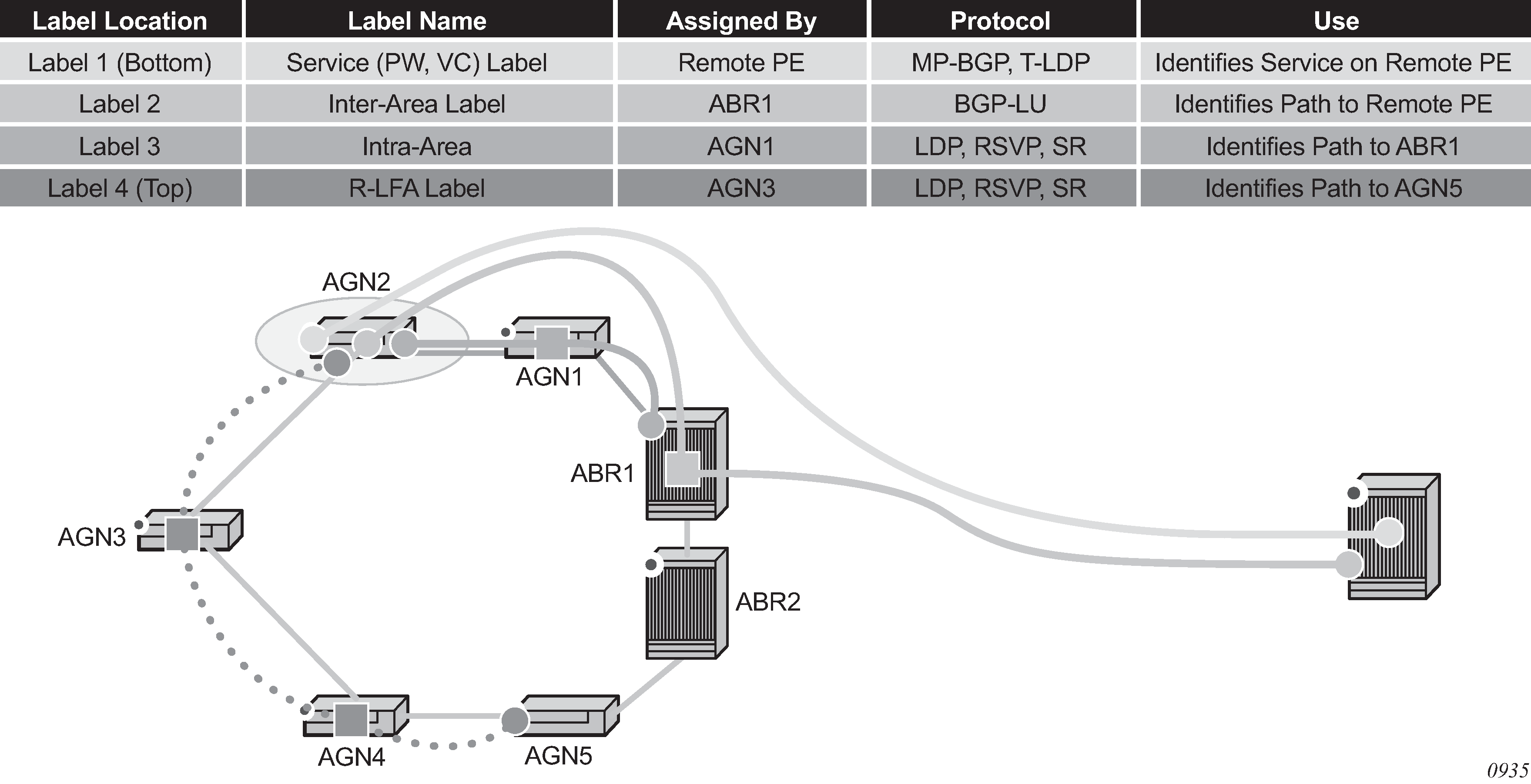
In MPLS deployments across multiple IGP areas or domains, such as in seamless MPLS design, it is challenging to provision FRR local protection in access and metro domains that use a ring, square, or partial mesh topology. To implement IP, LDP, or SR FRR in these topologies, the remote LFA feature must be implemented. Remote LFA provides a segment routing (SR) tunneled LFA next hop for an IP prefix, an LDP tunnel, or an SR tunnel. For prefixes outside of the area or domain, the access or aggregation router must push four labels: service label, BGP label for the destination PE, LDP/RSVP/SR label to reach the exit ABR/ASBR, and one label for the remote LFA next hop. Small routers deployed in these parts of the network have limited MPLS label stack size support.
Label stack for remote LFA in ring topology shows the label stack required for the primary next hop and the remote LFA next hop computed by aggregation node AGN2 for the inter-area prefix of a remote PE. For an inter-area BGP label unicast route prefix for which ABR1 is the primary exit ABR, AGN2 resolves the prefix to the transport tunnel of ABR1 and therefore, uses the remote LFA next hop of ABR1 for protection. The primary next hop uses two transport labels plus a service label. The remote LFA next hop for ABR1 uses PQ node AGN5 and pushes three transport labels plus a service label.
Seamless MPLS with Fast Restoration requires up to four labels to be pushed by AGN2, as shown in the following figure.
The objective of the LFA protection with a backup node SID feature is to reduce the label stack pushed by AGN2 for BGP label unicast inter-area prefixes. If link AGN2-AGN1 fails, packets are directed away from the failure and forwarded toward ABR2, which acts as the backup for ABR1 (and the other way around when ABR2 is the primary exit ABR for the BGP label unicast inter-area prefix). This requires ABR2 to advertise a special label for the loopback of ABR1 that will attract packets normally destined for ABR1. These packets are forwarded by ABR2 to ABR1 via the inter-ABR link.
As a result, AGN2 will push the label advertised by ABR2 to back up ABR1 in addition to the BGP label for the remote PE and the service label. This ensures that the label stack size for the LFA next hop is the same as that of the primary next hop. It is also the same size as the remote LFA next hop for the local prefix within the ring.
Detailed operation of LFA protection using backup node SID
As shown in the following figure, LFA for seamless MPLS supports environments where the boundary routers are either:
ABR nodes that connect with iBGP multiple domains, each using a different area of the same IGP instance
ASBR nodes that connect domains running different IGP instances and use iBGP within a domain and eBGP to the other domains
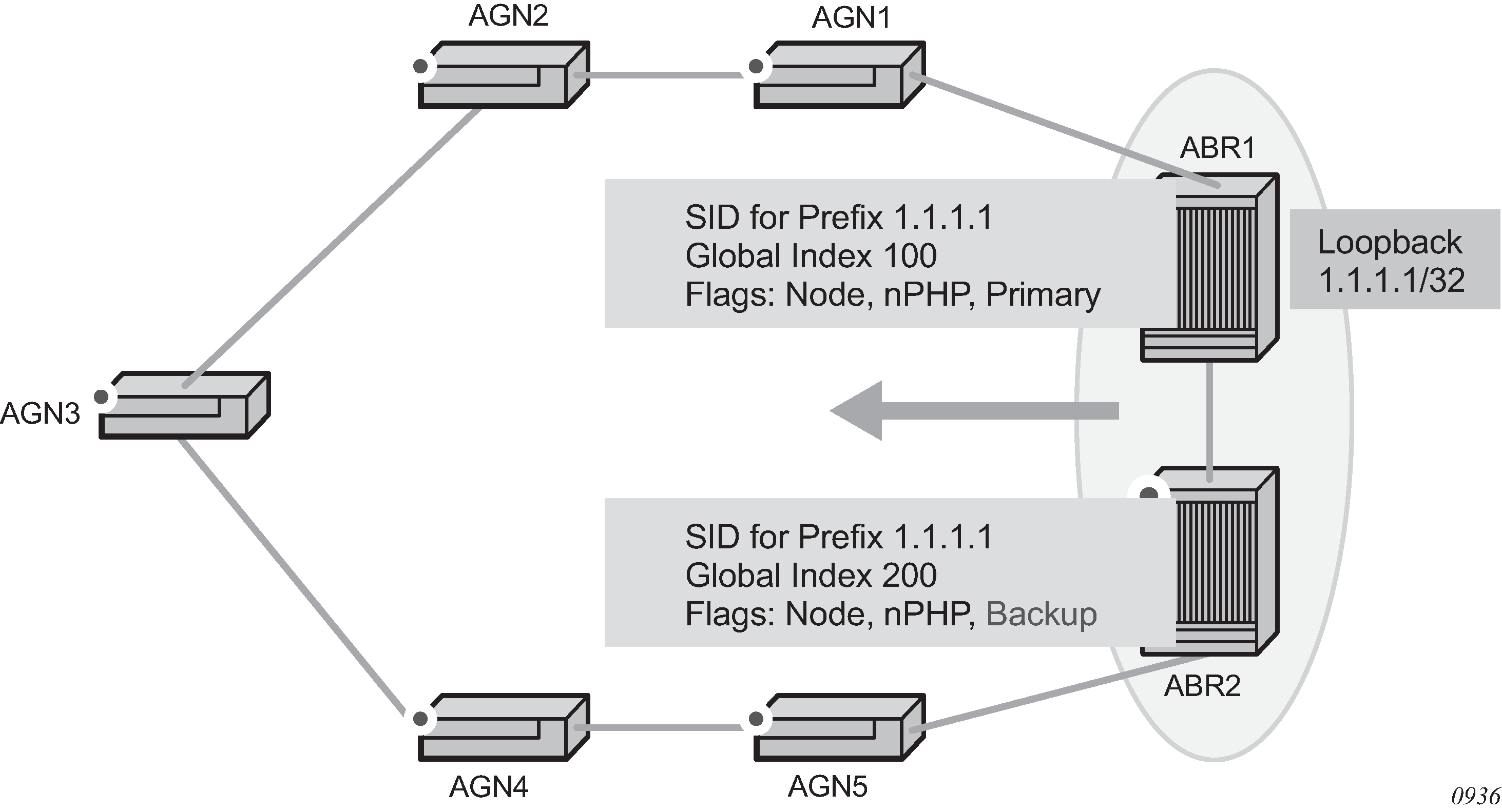
The following steps describe the configuration and behavior of LFA Protection using Backup Node SID, as shown in the preceding figure:
The user configures node SID 100 in ABR1 for its loopback prefix 1.1.1.1/32. This is the regular node SID. ABR1 advertises the prefix SID sub-TLV for this node SID in the IGP and installs the ILM using a unique label.
Each router receiving the prefix sub-TLV for node SID 100 resolves it as described in Segment routing in shortest path forwarding. Changes to the programming of the backup NHLFE of node SID 100 based on receiving the backup node SID for prefix 1.1.1.1/32 are defined in Duplicate SID handling.
The user configures a backup node SID 200 in ABR2 for the loopback 1.1.1.1/32 of ABR1. The SID value must be different from that assigned by ABR1 for the same prefix. ABR2 installs the ILM, which performs a swap operation from the label of SID 200 to that of SID 100. The ILM must point to a direct link and next hop to reach 1.1.1.1/32 of ABR1 as its primary next hop. The IGP examines all adjacencies established in the same area as that of prefix 1.1.1.1/32 and determines which ones have ABR1 as a direct neighbor and with the best cost. If more than one adjacency has the best cost, the IGP selects the one with the lowest interface index. If there is no adjacency to reach ABR2, the prefix SID for the backup node is flushed and is not resolved. This prevents the use of any non-direct path to reach ABR1. As a result, any received traffic on the ILM of SID 200 traffic will be blackholed.
If resolved, ABR2 advertises the prefix SID sub-TLV for this backup node SID 200 and indicates in the SR Algorithm field that a modified SPF algorithm, referred to as ‟Backup-constrained-SPF”, is required to resolve this node SID.
Each router receiving the prefix sub-TLV for the backup node SID 200 performs the following resolution steps. These steps do not require a CLI command to be enabled:
The router determines which router is being backed up. This is achieved by checking the router ID owner of the prefix sub-TLV that was advertised with the same prefix but without the backup flag and which is used as the best route for the prefix. In this case, it should be ABR1. Then the router runs a modified SPF by removing node ABR1 from the topology to resolve the backup node SID 200. The primary next hop should point to the path to ABR2 in the counter clockwise direction of the ring.
The router will not compute an LFA or a remote LFA for node SID 200 because the main SPF used a modified topology.
The router installs the ILM and primary NHLFE for the backup node SID.
Only a swap label operation is configured by all routers for the backup node SID. There is no push operation, and no tunnel for the backup node SID is added into the TTM.
The router programs the backup node SID as the LFA backup for the SR tunnel to node SID of 1.1.1.1/32 of ABR1. In other words, each router overrides the remote LFA backup for prefix 1.1.1.1/32, which is normally PQ node AGN5.
If the router is adjacent to ABR1, for example AGN1, it also programs the backup node SID as the LFA backup for the protection of any adjacency SID to ABR1.
When node AGN2 resolves a BGP label route for an inter-area prefix for which the primary ABR exit router is ABR1, it will use the backup node SID of ABR1 as the remote LFA backup instead of the SID to the PQ node (AGN5 in this example) to save on the pushed label stack.
AGN2 continues to resolve the prefix SID for any remote PE prefix that is summarized into the local area of AGN2 as usual. AGN2 programs a primary next hop and a remote LFA next hop. Remote LFA will use AGN5 as the PQ node and will push two labels, as it would for an intra-area prefix SID. There is no need to use the backup node SID for this prefix SID and force its backup path to go to ABR1. The backup path may exit from ABR2 if the cost from ABR2 to the destination prefix is shorter.
If the user excludes a link from LFA in the IGP instance (config>router>ospf>area>interface>loopfree-alternate-exclude), a backup node SID that resolves to that interface will not be used as a remote LFA backup in the same way as regular LFA or PQ remote LFA next hop behavior.
If the OSPF neighbor of a router is put into overload or if the metric of an OSPF interface to that neighbor is set to LSInfinity (0xFFFF), a backup node SID that resolves to that neighbor will not be used as a remote LFA backup in the same way as regular LFA or PQ remote LFA next hop behavior.
LFA policy is supported for IP next hops only. It is not supported with tunnel next hops such as IGP shortcuts or remote LFA tunnels. A backup node SID is also a tunnel next hop and, therefore, a user-configured LFA policy is not applied to check constraints such as admin-groups and SRLG against the outgoing interface of the selected backup node SID.
Duplicate SID handling
If the IGP issues or receives an LSA/LSP containing a prefix SID sub-TLV for a node SID or a backup node SID with a SID value that is a duplicate of an existing SID or backup node SID, the resolution in the following table is followed.
Old LSA/LSP |
New LSA/LSP |
|||
|---|---|---|---|---|
Backup node SID |
Local backup node SID |
Node SID |
Local node SID |
|
Backup Node SID |
Old |
New |
New |
New |
Local Backup Node SID |
Old |
Equal |
New |
New |
Node SID |
Old |
Old |
Equal/Old 1 |
Equal/New 2 |
Local Node SID |
Old |
Old |
Equal/Old 1 |
Equal/Old 1 |
OSPF control plane extensions
All routers supporting OSPF control plane extensions must advertise support of the new algorithm ‟Backup-constrained-SPF” of value 2 in the SR-Algorithm TLV, which is advertised in the Router Information Opaque LSA. This is in addition to the default supported algorithm ‟IGP-metric-based-SPF” of value 0. The following shows the encoding of the prefix SID sub-TLV to indicate a node SID of type backup and to indicate the modified SPF algorithm in the SR Algorithm field. The values used in the Flags field and in the Algorithm field are SR OS proprietary.
The new Algorithm (0x2) field and values are used by this feature.
0                   1                   2                   3
    0 1 2 3 4 5 6 7 8 9 0 1 2 3 4 5 6 7 8 9 0 1 2 3 4 5 6 7 8 9 0 1
   +-+-+-+-+-+-+-+-+-+-+-+-+-+-+-+-+-+-+-+-+-+-+-+-+-+-+-+-+-+-+-+-+
   |              Type             |             Length            |
   +-+-+-+-+-+-+-+-+-+-+-+-+-+-+-+-+-+-+-+-+-+-+-+-+-+-+-+-+-+-+-+-+
   |     Flags     |   Reserved    |      MT-ID    |Algorithm (0x2)|
   +-+-+-+-+-+-+-+-+-+-+-+-+-+-+-+-+-+-+-+-+-+-+-+-+-+-+-+-+-+-+-+-+
   |                     SID/Index/Label (variable)                |
   +-+-+-+-+-+-+-+-+-+-+-+-+-+-+-+-+-+-+-+-+-+-+-+-+-+-+-+-+-+-+-+-+
The following table lists OSPF control plane extension flag values.
Field |
Value |
|---|---|
Type |
2 |
Length |
variable |
Flags |
1 octet field |
The following flags are defined; the ‟B” flag is new:
     0  1  2  3  4  5  6  7
   +--+--+--+--+--+--+--+--+
   |  |NP|M |E |V |L | B|  |
   +--+--+--+--+--+--+--+--+
The following table describes OSPF control plane extension flags.
Flag |
Description |
|---|---|
NP-Flag |
No-PHP flag If set, the penultimate hop must not pop the prefix SID before delivering the packet to the node that advertised the prefix SID. |
M-Flag |
Mapping Server Flag If set, the SID is advertised from the Segment Routing Mapping Server functionality as described in I-D.filsfils-spring-segment-routing-ldp-interop. |
E-Flag |
Explicit-Null Flag If set, any upstream neighbor of the prefix SID originator must replace the prefix SID with a prefix SID having an Explicit-NULL value (0 for IPv4) before forwarding the packet. |
V-Flag |
Value/Index Flag If set, the prefix SID carries an absolute value. If not set, the prefix SID carries an index. |
L-Flag |
Local/Global Flag If set, the value/index carried by the prefix SID has local significance. If not set, then the value/index carried by this sub-TLV has global significance. |
B-Flag |
This flag is used by the Protection using backup node SID feature. If set, the SID is a backup SID for the prefix. This value is SR OS proprietary. |
Other bits |
Reserved These must be zero when sent and are ignored when received. |
MT-ID |
Multi-Topology ID, as defined in RFC 4915 |
Algorithm |
One octet identifying the algorithm the prefix SID is associated with. A value of (0x2) indicates the modified SPF algorithm, which removes from the topology the node that is backed up by the backup node SID. This value is SR OS proprietary. |
SID/Index/Label |
Based on the V and L flags, it contains either:
|
OSPF configuration process overview
The following figure shows the process to provision basic OSPF parameters.

Configuration notes
This section describes OSPF configuration caveats.
General
Before OSPF can be configured, the router ID must be configured.
The basic OSPF configuration includes at least one area and an associated interface.
All default and command parameters can be modified.
OSPF defaults
The following list summarizes the OSPF configuration defaults:
By default, a router has no configured areas.
An OSPF instance is created in the administratively enabled state.
Configuring OSPF with CLI
This section provides information to configure Open Shortest Path First (OSPF) using the command line interface.
OSPF configuration guidelines
Configuration planning is essential to organize routers, backbone, non-backbone, stub, NSSA areas, and transit links. OSPF provides essential defaults for basic protocol operability. You can configure or modify commands and parameters. OSPF is not enabled by default.
The minimal OSPF parameters which should be configured to deploy OSPF are:
Router ID
Each router running OSPF must be configured with a unique router ID. The router ID is used by OSPF routing protocols in the routing table manager.
When configuring a new router ID, protocols will not automatically be restarted with the new router ID. Shut down and restart the protocol to initialize the new router ID.
OSPF instance
OSPF instances must be defined when configuring multiple instances and/or the instance being configured is not the base instance.
An area
At least one OSPF area must be created. An interface must be assigned to each OSPF area.
Interfaces
An interface is the connection between a router and one of its attached networks. An interface has state information associated with it, which is obtained from the underlying lower level protocols and the routing protocol. An interface to a network has associated with it a single IP address and mask (unless the network is an unnumbered point-to-point network). An interface is sometimes also referred to as a link.
Basic OSPF configuration
This section provides information to configure the basic parameter for OSPF and OSPFv3 as well as configuration examples of common configuration tasks.
The minimal OSPF parameters that need to be configured are:
router ID
If a router-id is not configured in the config>router context, the router's system interface IP address is used.
one or more areas
interfaces
(interface "system")
Basic OSPF configuration output
SAS-A>config>router>ospf# info
----------------------------------------------
            area 0.0.0.0
                interface "system"
                exit
            exit
            area 0.0.0.20
                nssa
                exit
                interface "to-104"
                    priority 10
                exit
            exit
            area 0.0.1.1
            exit
----------------------------------------------
SAS-A>config>router>ospf#
Basic OSPFv3 configuration output
SAS-A>config>router>ospf3# info
----------------------------------------------
            asbr
            overload
                lsa-arrival 50000
                exit
            exit
            export "OSPF-Export"
            area 0.0.0.0
                interface "system"
                exit
            exit
            area 0.0.1.20
                nssa
                exit
                interface "SR1-2"
                exit
            exit
----------------------------------------------
SAS-A>config>router>ospf#
Configuring the router ID
The router ID uniquely identifies the router within an AS. In OSPF, routing information is exchanged between autonomous systems, groups of networks that share routing information. It can be set to be the same as the loopback (system interface) address. Subscriber services also use this address as far-end router identifiers when service distribution paths (SDPs) are created. The router ID is used by both OSPF and BGP routing protocols. A router ID can be derived by:
Defining the value in the config>router router-id context.
Defining the system interface in the config>router>interface ip-int-name context (used if the router ID is not specified in the config>router router-id context).
Inheriting the last four bytes of the MAC address.
On the BGP protocol level. A BGP router ID can be defined in the config>router>bgp router-id context and is only used within BGP.
When configuring a new router ID, protocols are not automatically restarted with the new router ID. The next time a protocol is (re) initialized the new router ID is used. An interim period of time can occur when different protocols use different router IDs. To force the new router ID, issue the shutdown and no shutdown commands for each protocol that uses the router ID or restart the entire router.
Router ID configuration output
A:ALA-B>config>router# info
#------------------------------------------
# IP Configuration
#------------------------------------------
        interface "system"
            address 10.10.10.104/32
        exit
        interface "to-103"
            address 10.0.0.104/24
            port 1/1/1
        exit
router-id 10.10.10.104
...
#------------------------------------------
A:ALA-B>config>router#
Configuring OSPF components
The following section describes the syntax used to configure the OSPF components.
Configuring OSPF parameters
Basic OSPF configuration output
A:SAS-12>config>router>ospf# info
----------------------------------------------
            asbr
            overload
            overload-on-boot timeout 60
            traffic-engineering
            export "OSPF-Export"
            graceful-restart
                helper-disable
            exit
----------------------------------------------
A:SAS-12>config>router>ospf# ex
Configuring OSPFv3 parameters
Use the following syntax to configure OSPF3 parameters.
config>router# ospf3
        asbr
        export policy-name [policy-name...(up to 5 max)]
        external-db-overflow limit seconds
        external-preference preference
        overload [timeout seconds]
        overload-include-stub
        overload-on-boot [timeout seconds]
        preference preference
        reference-bandwidth bandwidth-in-kbps
        router-id ip-address
        no shutdown
        timers
            lsa-arrival lsa-arrival-time
            lsa-generate max-lsa-wait [lsa-initial-wait lsa-initial-wait [lsa-second-wait lsa-second-wait]]
            spf-wait max-spf-wait [spf-initial-wait spf-initial-wait [spf-second-wait spf-second-wait]]
OSPF3 configuration output
A:SAS-12>config>router>ospf3# info
----------------------------------------------
            asbr
            overload
            timers
                lsa-arrival 50000
            exit
            export "OSPF-Export"
----------------------------------------------
A:SAS-12>config>router>ospf3#
OSPF also supports the concept of multi-instance OSPFv2 and OSPFv3 which allows separate instances of the OSPF protocols to run independently within SR OSs.
Separate instances are created by adding a different instance ID as the optional parameter to the config>router>ospf and config>router>ospf3 commands. When this is done a separate OSPF instance is created which maintains separate link state databases for each instance.
Configuring an OSPF and OSPFv3 area
An OSPF area consists of routers configured with the same area ID. To include a router in a specific area, the common area ID must be assigned and an interface identified.
If a network consists of multiple areas you must also configure a backbone area (0.0.0.0) on at least one router. The backbone is comprised of the area border routers and other routers not included in other areas. The backbone distributes routing information between areas. The backbone is considered to be a participating area within the autonomous system. To maintain backbone connectivity, there must be at least one interface in the backbone area or have a virtual link configured to another router in the backbone area.
The minimal configuration must include an area ID and an interface. Modifying other command parameters are optional.
Use the following syntax to configure an OSPF area.
ospf ospf-instance
	area area-id
    area-range ip-prefix/mask [advertise|not-advertise]
    blackhole-aggregate
Use the following syntax to configure an OSPFv3 area.
ospf ospf-instance
    ospf3
    area area-id
        area-range ip-prefix/mask [advertise|not-advertise]
        blackhole-aggregate
OSPF area configuration output
A:ALA-A>config>router>ospf# info
----------------------------------------------
            area 0.0.0.0
            exit
            area 0.0.0.20
            exit
----------------------------------------------
ALA-A>config>router>ospf#A:
Configuring an OSPF and OSPFv3 stub area
Configure stub areas to control external advertisements flooding and to minimize the size of the topological databases on an area's routers. A stub area cannot also be configured as an NSSA.
By default, summary route advertisements are sent into stub areas. The no form of the summary command disables sending summary route advertisements and only the default route is advertised by the ABR. This example retains the default so the command is not entered.
If this area is configured as a transit area for a virtual link, then existing virtual links of a non-stub or NSSA area are removed when its designation is changed to NSSA or stub.
Stub areas for OSPFv3 are configured the same as for OSPF.
Use the following syntax to configure an OSPF stub area.
ospf
        area area-id
        stub
        default-metric metric
        summaries
The following is a sample stub configuration output.
SAS-12>config>router>ospf>area># info
----------------------------------------------
...
            area 0.0.0.0
            exit
            area 0.0.0.20
  stub
                exit
            exit
...
----------------------------------------------
SAS-12>config>router>ospf#
Configuring a Not-So-Stubby Area
You must explicitly configure an area to be a Not-So-Stubby Area (NSSA) area. NSSAs are similar to stub areas in that no external routes are imported into the area from other OSPF areas. The major difference between a stub area and an NSSA is an NSSA has the capability to flood external routes it learns throughout its area and by an area border router to the entire OSPF domain. An area cannot be both a stub area and an NSSA.
If this area is configured as a transit area for a virtual link, then existing virtual links of a non-stub or NSSA area are removed when its designation is changed to NSSA or stub.
Use the following syntax to configure an NSSA for OSPF.
ospf ospf-instance
            area area-id
        nssa
            area-range ip-prefix/mask [advertise|not-advertise]
            originate-default-route [type-7]
            redistribute-external
            summaries
Use the following syntax to configure stub areas for the OSPFv3.
ospf ospf-instance
    ospf3
            area area-id
        nssa
            area-range ip-prefix/mask [advertise|not-advertise]
            originate-default-route [type-7]
            redistribute-external
            summaries
NSSA configuration output
A:SAS-12>config>router>ospf# info
----------------------------------------------
            asbr
            overload
            overload-on-boot timeout 60
            traffic-engineering
            export "OSPF-Export"
            exit
            area 0.0.0.0
            exit
            area 0.0.0.20
                stub
                exit
            exit
            area 0.0.0.25
                nssa
                exit
            exit
----------------------------------------------
A:SAS-12>config>router>ospf#
OSPFv3 NSSA configuration output
A:SAS-12>config>router>ospf3# info
----------------------------------------------
            asbr
            overload
            timers
                lsa-arrival 50000
            exit
            export "OSPF-Export"
            area 0.0.0.0
            exit
            area 0.0.0.20
                stub
                exit
            exit
            area 0.0.0.25
                nssa
                exit
            exit
            area 4.3.2.1
            exit
----------------------------------------------
A:SAS-12>config>router>ospf3#
Configuring a virtual link
The backbone area (area 0.0.0.0) must be contiguous and all other areas must be connected to the backbone area. If it is not practical to connect an area to the backbone then the area border routers must be connected via a virtual link. The two area border routers will form a point-to-point-like adjacency across the transit area. A virtual link can only be configured while in the area 0.0.0.0 context.
The router-id parameter specified in the virtual-link command must be associated with the virtual neighbor, that is, enter the virtual neighbor’s router ID, not the local router ID. The transit area cannot be a stub area or an NSSA.
Use the following syntax to configure a virtual link.
ospf ospf-instance
        area area-id
    virtual-link router-id transit-area area-id
        authentication-key [authentication-key|hash-key] [hash]
        authentication-type [password|message-digest]
        dead-interval seconds
        hello-interval seconds
        message-digest-key key-id md5 [key|hash-key] [hash|hash2]
        retransmit-interval seconds
        transit-delay
        no shutdown
Virtual link configuration output
A:SAS-12>config>router>ospf# info
----------------------------------------------
            asbr
            overload
            overload-on-boot timeout 60
            traffic-engineering
            export "OSPF-Export"
            graceful-restart
                helper-disable
            exit
            area 0.0.0.0
                virtual-link 1.2.3.4 transit-area 1.2.3.4
                    hello-interval 9
                    dead-interval 40
                exit
            exit
            area 0.0.0.20
                stub
                exit
            exit
            area 0.0.0.25
                nssa
                exit
            exit
            area 1.2.3.4
            exit
----------------------------------------------
A:SAS-12>config>router>ospf#
Configuring an interface
In OSPF, an interface can be configured to act as a connection between a router and one of its attached networks. An interface includes state information that was obtained from underlying lower level protocols and from the routing protocol. An interface to a network is associated with a single IP address and mask. If the address is merely changed, then the OSPF configuration is preserved.
The passive command enables the passive property to and from the OSPF interface where passive interfaces are advertised as OSPF interfaces but do not run the OSPF protocol. By default, only interface addresses that are configured for OSPF are advertised as OSPF interfaces. The passive parameter allows an interface to be advertised as an OSPF interface without running the OSPF protocol. When enabled, the interface will ignore ingress OSPF protocol packets and not transmit any OSPF protocol packets.
An interface can be part of more than one area, as specified in RFC 5185. To do this, add the keyword secondary when creating the interface.
Use the following syntax to configure an OSPF interface.
ospf ospf-instance
        area area-id
    interface ip-int-name
        advertise-subnet
        authentication-key [authentication-key|hash-key] [hash|hash2]
        authentication-type [password|message-digest]
        dead-interval seconds
        hello-interval seconds
        interface-type {broadcast|point-to-point}
        message-digest-key key-id md5 [key|hash-key][hash|hash2]
        metric metric
        mtu bytes
        passive
        priority number
        retransmit-interval seconds
        no shutdown
        transit-delay seconds
The following is a sample interface configuration output.
A:ALA-49>config>router>ospf# info
----------------------------------------------
            asbr
            overload
            overload-on-boot timeout 60
            traffic-engineering
            export "OSPF-Export"
            graceful-restart
                helper-disable
            exit
            area 0.0.0.0
                virtual-link 1.2.3.4 transit-area 1.2.3.4
                    hello-interval 9
                    dead-interval 40
                exit
                interface "system"
                exit
            exit
            area 0.0.0.20
                stub
                exit
                interface "to-103"
                exit
            exit
            area 0.0.0.25
                nssa
                exit
            exit
            area 1.2.3.4
            exit
 area 4.3.2.1
                interface "SR1-3"
                exit
            exit
            area 4.3.2.1
                interface "SR1-3" secondary
                exit
            exit
----------------------------------------------
A:ALA-49>config>router>ospf# area 0.0.0.20
Configuring authentication
Authentication must be explicitly configured. The following authentication commands can be configured on the interface level or the virtual link level:
authentication-key
Configures the password used by the OSPF interface or virtual-link to send and receive OSPF protocol packets on the interface when simple password authentication is configured.
authentication-type
Enables authentication and specifies the type of authentication to be used on the OSPF interface, either password or message digest.
message-digest-key
Use this command when the message-digest keyword is selected in the authentication-typecommand. The Message Digest 5 (MD5) hashing algorithm is used for authentication. MD5 is used to verify data integrity by creating a 128-bit message digest from the data input. It is unique to that specific data.
An special checksum is included in transmitted packets and are used by the far-end router to verify the packet by using an authentication key (a password). Routers on both ends must use the same MD5 key.
MD5 can be configured on each interface and each virtual link. If MD5 is enabled on an interface, then that interface accepts routing updates only if the MD5 authentication is accepted. Updates that are not authenticated are rejected. A router accepts only OSPF packets sent with the same key-id value defined for the interface.
When the hash parameter is not used, non-encrypted characters can be entered. When configured using the message-digest-key command, then all keys specified in the command are stored in encrypted format in the configuration file using the hash keyword. When using the hash keyword the password must be entered in encrypted form. Hashing cannot be reversed. Issue the no message-digest-key key-id command and then re-enter the command without the hash parameter to configure an unhashed key.
The following CLI commands are displayed to illustrate the key authentication features. These command parameters can be defined at the same time interfaces and virtual-links are being configured. See Configuring an interface and Configuring a virtual link.
Use the following syntax to configure authentication.
ospf ospf-instance
        area area-id
    interface ip-int-name
        authentication-key [authentication-key|hash-key] [hash]
        authentication-type [password|message-digest]
        message-digest-key key-id md5 key[hash]
    virtual-link router-id transit-area area-id
        authentication-key [authentication-key|hash-key] [hash]
        authentication-type [password|message-digest]
        message-digest-key key-id md5 key[hash]
Authentication configuration output
A:ALA-49>config>router>ospf# info
----------------------------------------------
            asbr
            overload
            overload-on-boot timeout 60
            traffic-engineering
            export "OSPF-Export"
            graceful-restart
                helper-disable
            exit
            area 0.0.0.0
                virtual-link 1.2.3.4 transit-area 1.2.3.4
                    hello-interval 9
                    dead-interval 40
                exit
                interface "system"
                exit
            exit
            area 0.0.0.20
                stub
                exit
                interface "to-103"
                exit
            exit
            area 0.0.0.25
                nssa
                exit
            exit
            area 0.0.0.40
                interface "test1"
                    authentication-type password
                    authentication-key "3WErEDozxyQ" hash
                exit
            exit
            area 1.2.3.4
            exit
----------------------------------------------
A:ALA-49>config>router>ospf#
A:ALA-49>config>router>ospf# info
----------------------------------------------
            asbr
            overload
            overload-on-boot timeout 60
            traffic-engineering
            export "OSPF-Export"
            graceful-restart
                helper-disable
            exit
            area 0.0.0.0
                virtual-link 10.0.0.1 transit-area 0.0.0.1
                    authentication-type message-digest
                    message-digest-key 2 md5 "Mi6BQAFi3MI" hash
                exit
                virtual-link 1.2.3.4 transit-area 1.2.3.4
                    hello-interval 9
                    dead-interval 40
                exit
                interface "system"
                exit
            exit
            area 0.0.0.1
            exit
            area 0.0.0.20
                stub
                exit
                interface "to-103"
                exit
            exit
            area 0.0.0.25
                nssa
                exit
            exit
            area 0.0.0.40
                interface "test1"
                    authentication-type password
                    authentication-key "3WErEDozxyQ" hash
                exit
            exit
            area 1.2.3.4
            exit
----------------------------------------------
A:ALA-49>config>router>ospf#
Assigning a designated router
A designated router is elected according to the priority number advertised by the routers. When a router starts up, it checks for a current designated router. If a designated router is present, then the router accepts that designated router, regardless of its own priority designation. When a router fails, then new designated and backup routers are elected according their priority numbers.
The priority command is only used if the interface is a broadcast type. The designated router is responsible for flooding network link advertisements on a broadcast network to describe the routers attached to the network. A router uses hello packets to advertise its priority. The router with the highest priority interface becomes the designated router. A router with priority 0 is not eligible to be a designated router or a backup designated router. At least one router on each logical IP network or subnet must be eligible to be the designated router. By default, routers have a priority value of 1.
Use the following syntax to configure the designated router.
ospf ospf-instance
        area area-id
    interface ip-int-name
        priority number
Priority designation output
A:ALA-49>config>router>ospf# info
----------------------------------------------
            asbr
            overload
            overload-on-boot timeout 60
            traffic-engineering
            export "OSPF-Export"
            graceful-restart
                helper-disable
            exit
            area 0.0.0.0
                virtual-link 10.0.0.1 transit-area 0.0.0.1
                    authentication-type message-digest
                    message-digest-key 2 md5 "Mi6BQAFi3MI" hash
                exit
                virtual-link 1.2.3.4 transit-area 1.2.3.4
                    hello-interval 9
                    dead-interval 40
                exit
                interface "system"
                exit
            exit
            area 0.0.0.1
            exit
            area 0.0.0.20
                stub
                exit
                interface "to-103"
                exit
            exit
            area 0.0.0.25
                nssa
                exit
                interface "if2"
                    priority 100
                exit
            exit
            area 0.0.0.40
                interface "test1"
                    authentication-type password
                    authentication-key "3WErEDozxyQ" hash
                exit
            exit
            area 1.2.3.4
            exit
----------------------------------------------
A:ALA-49>config>router>ospf#
Configuring route summaries
Area border routers send summary (type 3) advertisements into a stub area or NSSA to describe the routes to other areas. This command is particularly useful to reduce the size of the routing and Link State Database (LSDB) tables within the stub or NSSA.
By default, summary route advertisements are sent into the stub area or NSSA. The no form of the summaries command disables sending summary route advertisements and, in stub areas, the default route is advertised by the area border router.
The following CLI commands are displayed to illustrate route summary features. These command parameters can be defined at the same time stub areas and NSSAs are being configured. See Configuring an OSPF and OSPFv3 stub area and Configuring a Not-So-Stubby Area.
Route summaries for OSPF3 are configured the same as for OSPF.
Use the following syntax to configure a route summary.
ospf ospf-instance
        area area-id
    stub
        summaries
    nssa
        summaries
Stub route summary configuration output
A:SAS-12>config>router>ospf# info
----------------------------------------------
            asbr
            overload
            overload-on-boot timeout 60
            traffic-engineering
            export "OSPF-Export"
            graceful-restart
                helper-disable
            exit
            area 0.0.0.0
                virtual-link 10.0.0.1 transit-area 0.0.0.1
                    authentication-type message-digest
                    message-digest-key 2 md5 "Mi6BQAFi3MI" hash
                exit
                virtual-link 1.2.3.4 transit-area 1.2.3.4
                    hello-interval 9
                    dead-interval 40
                exit
                interface "system"
                exit
            exit
            area 0.0.0.1
            exit
            area 0.0.0.20
                stub
                exit
                interface "to-103"
                exit
            exit
            area 0.0.0.25
                nssa
                exit
                interface "if2"
                    priority 100
                exit
            exit
            area 0.0.0.40
                interface "test1"
                    authentication-type password
                    authentication-key "3WErEDozxyQ" hash
                exit
            exit
            area 1.2.3.4
            exit
----------------------------------------------
A:SAS-12>config>router>ospf#
Stub route summary OSPv3 configuration output
A:SAS-12>config>router>ospf3# info
----------------------------------------------
            asbr
            overload
            timers
                lsa-arrival 50000
            exit
            export "OSPF-Export"
            area 0.0.0.0
                virtual-link 4.3.2.1 transit-area 4.3.2.1
                exit
                interface "system"
                exit
            exit
            area 0.0.0.20
                stub
                exit
                interface "SR1-2"
                exit
            exit
            area 0.0.0.25
                nssa
                exit
            exit
            area 4.3.2.1
            exit
----------------------------------------------
A:SAS-12>config>router>ospf3#
Configuring route preferences
A route can be learned by the router from different protocols, in which case, the costs are not comparable. When this occurs the preference value is used to decide which route is installed in the forwarding table if several protocols calculate routes to the same destination. The route with the lowest preference value is selected
Different protocols should not be configured with the same preference, if this occurs the tiebreaker is per the default preference table as described in the following table. If multiple routes are learned with an identical preference using the same protocol, the lowest cost route is used.
Route type |
Preference |
Configurable |
|---|---|---|
Direct attached |
0 |
No |
Static routes |
5 |
Yes |
OSPF/ OSPFv3 internal |
10 |
Yes |
IS-IS level 1 internal |
15 |
Yes |
IS-IS level 2 internal |
18 |
Yes |
OSPF/ OSPFv3 external |
150 |
Yes |
IS-IS level 1 external |
160 |
Yes |
IS-IS level 2 external |
165 |
Yes |
BGP |
170 |
Yes |
Preference for OSPF and OSPFv3 internal routes is configured with the preference command.
The following CLI commands are displayed to illustrate route preference features. The command parameters can be defined at the same time you are configuring OSPF. See Configuring OSPF components.
Route parameters for OSPFv3 are configured the same as for OSPF.
Use the following syntax to configure a route preference.
ospf ospf-instance
        preference preference
        external-preference preference
Route preference configuration output
A:ALA-49>config>router>ospf# info
----------------------------------------------
            asbr
            overload
            overload-on-boot timeout 60
            traffic-engineering
            preference 9
            external-preference 140
            export "OSPF-Export"
            graceful-restart
                helper-disable
            exit
            area 0.0.0.0
                virtual-link 10.0.0.1 transit-area 0.0.0.1
                    authentication-type message-digest
                    message-digest-key 2 md5 "Mi6BQAFi3MI" hash
                exit
                virtual-link 1.2.3.4 transit-area 1.2.3.4
                    hello-interval 9
                    dead-interval 40
                exit
                interface "system"
                exit
            exit
            area 0.0.0.1
            exit
            area 0.0.0.20
                stub
                exit
                interface "to-103"
                exit
            exit
            area 0.0.0.25
                nssa
                exit
                interface "if2"
                    priority 100
                exit
            exit
            area 0.0.0.40
                interface "test1"
                    authentication-type password
                    authentication-key "3WErEDozxyQ" hash
                exit
            exit
            area 1.2.3.4
            exit
----------------------------------------------
OSPF configuration management tasks
This section describes the OSPF configuration management tasks.
Modifying a router ID
Because the router ID is defined in the config>router context, not in the OSPF configuration context, the protocol instance is not aware of the change. Re-examine the plan detailing the router ID. Changing the router ID on a device could cause configuration inconsistencies if associated values are not also modified.
After you have changed a router ID, manually shut down and restart the protocol using the shutdown and no shutdown commands in order for the changes to be incorporated.
Use the following syntax to change a router ID number.
config>router# router-id router-id
NSSA router ID modification output
A:ALA-49>config>router# info
------------------------------------------
IP Configuration
------------------------------------------
        interface "system"
            address 10.10.10.104/32
        exit
        interface "to-103"
            address 10.0.0.103/24
            port 1/1/1
        exit
router-id 10.10.10.104
------------------------------------------
A:ALA-49>config>router#
Deleting a router ID
You can modify a router ID, but you cannot delete the parameter. When the no router router-id command is issued, the router ID reverts to the default value, the system interface address (which is also the loopback address). If a system interface address is not configured, then the last 32 bits of the chassis MAC address is used as the router ID.
Modifying OSPF parameters
You can change or remove existing OSPF parameters in the CLI or NMS. The changes are applied immediately.
The following is a sample OSPF modification in which an interface is removed and another interface added.
config>router# ospf 1
    config>router>ospf# area 0.0.0.20
    config>router>ospf>area# no interface "to-103"
    config>router>ospf>area# interface "to-HQ
    config>router>ospf>area>if$ priority 50
    config>router>ospf>area>if# exit
    config>router>ospf>area# exit
The following is a sample OSPF configuration output with the modifications entered in the previous sample.
A:ALA-49>config>router>ospf# info
----------------------------------------------
            asbr
            overload
            overload-on-boot timeout 60
            traffic-engineering
            preference 9
            external-preference 140
            export "OSPF-Export"
            graceful-restart
                helper-disable
            exit
            area 0.0.0.0
                virtual-link 10.0.0.1 transit-area 0.0.0.1
                    authentication-type message-digest
                    message-digest-key 2 md5 "Mi6BQAFi3MI" hash
                exit
                virtual-link 1.2.3.4 transit-area 1.2.3.4
                    hello-interval 9
                    dead-interval 40
                exit
                interface "system"
                exit
            exit
            area 0.0.0.1
            exit
            area 0.0.0.20
                stub
                exit
                interface "to-HQ"
                    priority 50
                exit
            exit
            area 0.0.0.25
                nssa
                exit
                interface "if2"
                    priority 100
                exit
            exit
            area 0.0.0.40
                interface "test1"
                    authentication-type password
                    authentication-key "3WErEDozxyQ" hash
                exit
            exit
            area 1.2.3.4
            exit
----------------------------------------------
A:ALA-49>config>router>ospf#
OSPF command reference
Command hierarchies
Configuration commands for OSPF
config
    - router
        - [no] ospf [router-id]
            - advertise-router-capability {link | area | as}
            - no advertise-router-capability
            - [no] area area-id
                - area-range ipv4-prefix/mask | ipv6-prefix/prefixlength [advertise | not-advertise]
                - no area-range ipv4-prefix/mask | ipv6-prefix/prefixlength
                - [no] blackhole-aggregate
                - [no] interface ip-int-name [secondary]
                    - authentication-key [authentication-key | hash-key] [hash | hash2]
                    - no authentication-key
                    - authentication-type {password | message-digest}
                    - no authentication-type
                    - bfd-enable [remain-down-on-failure]
                    - no bfd-enable
                    - dead-interval seconds
                    - no dead-interval
                    - hello-interval seconds
                    - no hello-interval
                    - interface-type {broadcast | point-to-point}
                    - no interface-type
                    - [no] loopfree-alternate-exclude
                    - message-digest-key key-id md5 [key | hash-key] [hash | hash2]
                    - no message-digest-key key-id
                    - metric metric
                    - no metric
                    - mtu bytes
                    - no mtu
                    - node-sid index value
                    - node-sid label value
                    - no node-sid
                    - [no] passive
                    - priority number
                    - no priority
                    - retransmit-interval seconds
                    - no retransmit-interval
                    - [no] shutdown
                    - transit-delay seconds
                    - no transit-delay
                - [no] loopfree-alternate-exclude
                - [no] nssa
                    - area-range ipv4-prefix/mask | ipv6-prefix/prefixlength [advertise | not-advertise]
                    - no area-range ipv4-prefix/mask | ipv6-prefix/prefixlength
                    - originate-default-route [type-7]
                    - no originate-default-route
                    - [no] redistribute-external
                    - [no] summaries
                - [no] stub
                    - default-metric metric
                    - no default-metric
                    - [no] summaries
                - [no] virtual-link router-id transit-area area-id
                    - authentication-key [authentication-key | hash-key] [hash | hash2]
                    - no authentication-key
                    - authentication-type {password | message-digest}
                    - no authentication-type
                    - dead-interval seconds
                    - no dead-interval
                    - hello-interval seconds
                    - no hello-interval
                    - message-digest-key key-id md5 [key | hash-key] [hash | hash2]
                    - no message-digest-key key-id
                    - retransmit-interval seconds
                    - no retransmit-interval
                    - [no] shutdown
                    - transit-delay seconds
                    - no transit-delay
            - [no] asbr [trace-path domain-id]
            - [no] compatible-rfc1583
            - [no] disable-ldp-sync
            - export policy-name [ policy-name...(up to 5 max)]
            - no export
            - export-limit number [log percentage]
            - no export-limit
            - external-db-overflow limit seconds
            - no external-db-overflow
            - external-preference preference
            - no external-preference
            - [no] graceful-restart
                - [no] helper-disable
            - loopfree-alternate [remote-lfa]
            - loopfree-alternate remote-lfa [max-pq-cost value]
            - no loopfree-alternate
            - loopfree-alternate-exclude prefix-policy prefix-policy [prefix-policy ... (up to 5)]
            - no loopfree-alternate-exclude
            - overload [timeout seconds]
            - no overload
            - [no] overload-include-stub
            - overload-on-boot [timeout seconds]
            - no overload-on-boot
            - preference preference
            - no preference
            - reference-bandwidth bandwidth-in-kbps
            - no reference-bandwidth
            - router-id ip-address
            - no router-id
            - segment-routing
            - no segment-routing
                - prefix-sid-range {global | start-label label-value max-index index-value}
                - no prefix-sid-range
                - tunnel-mtu bytes
                - no tunnel-mtu
                - tunnel-table-pref preference
                - no tunnel-table-pref
                - [no] shutdown
            - [no] shutdown
            - timers
                - [no] lsa-arrival lsa-arrival-time
                - [no] lsa-generate max-lsa-wait [lsa-initial-wait [lsa-second-wait]]
                - [no] spf-wait max-spf-wait [spf-initial-wait [spf-second-wait]]
            - [no] traffic-engineering
        - [no] ospf3 router-id
            - [no] area area-id
                - area-range ipv4-prefix/mask | ipv6-prefix/prefixlength [advertise | not-advertise]
                - no area-range ipv4-prefix/mask | ipv6-prefix/prefixlength
                - [no] blackhole-aggregate
                - [no] interface ip-int-name [secondary]
                    - authentication bidirectional sa-name
                    - authentication inbound sa-name outbound sa-name
                    - no authentication
                    - dead-interval seconds
                    - no dead-interval
                    - hello-interval seconds
                    - no hello-interval
                    - interface-type {broadcast | point-to-point}
                    - no interface-type
                    - [no] loopfree-alternate-exclude
                    - metric metric
                    - no metric
                    - mtu bytes
                    - no mtu
                    - [no] passive
                    - priority number
                    - no priority
                    - retransmit-interval seconds
                    - no retransmit-interval
                    - [no] shutdown
                    - transit-delay seconds
                    - no transit-delay
                - key-rollover-interval
                - no key-rollover-interval
                - [no] nssa
                    - area-range ipv4-prefix/mask | ipv6-prefix/prefixlength [advertise | not-advertise]
                    - no area-range ipv4-prefix/mask | ipv6-prefix/prefixlength
                    - originate-default-route [type-nssa]
                    - no originate-default-route
                    - [no] redistribute-external
                    - [no] summaries
                - [no] stub
                    - default-metric metric
                    - no default-metric
                    - [no] summaries
                - [no] virtual-link router-id transit-area area-id
                    - authentication bidirectional sa-name
                    - authentication inbound sa-name outbound sa-name
                    - no authentication
                    - dead-interval seconds
                    - no dead-interval
                    - hello-interval seconds
                    - no hello-interval
                    - retransmit-interval seconds
                    - no retransmit-interval
                    - [no] shutdown
                    - transit-delay seconds
                    - no transit-delay
            - [no] asbr [trace-path domain-id]
            - export policy-name [policy-name...(up to 5 max)]
            - no export
            - export-limit number [log percentage]
            - no export-limit
            - external-db-overflow limit seconds
            - no external-db-overflow
            - external-preference preference
            - no external-preference
            - [no] graceful-restart
                - [no] helper-disable
            - import policy-name [policy-name…(up to 15 max)]
            - no import policy-name
            - overload [timeout seconds]
            - no overload
            - [no] overload-include-stub
            - overload-on-boot [timeout seconds]
            - no overload-on-boot
            - preference preference
            - no preference
            - reference-bandwidth bandwidth-in-kbps
            - reference-bandwidth [tbps Tera-bps] [gbps Giga-bps] [mbps Mega-bps] [kbps Kilo-bps]
            - no reference-bandwidth
            - router-id ip-address
            - no router-id
            - [no] shutdown
            - timers
                - [no] lsa-arrival lsa-arrival-time
                - [no] lsa-generate max-lsa-wait [lsa-initial-wait [lsa-second-wait]]
                - [no] spf-wait max-spf-wait [spf-initial-wait [spf-second-wait]]
Show commands
show
    - router
        - ospf
            - area [area-id] [detail]
            - database [type {router | network | summary | asbr-summary | external | nssa | all} [area area-id] [adv-router router-id] [link-state-id] [detail]
            - interface [ip-int-name | ip-address] [detail]]
            - interface [area area-id] [detail]
            - neighbor [ip-int-name] [router-id] [detail]
            - prefix-sids [ip-prefix [/prefix-length]] [sid sid] [adv-router router-id]
            - range [area-id]
            - routes [ip-prefix[/prefix-length]] [type] [detail] [alternative] [summary] [exclude-shortcut]
            - spf [interface-name] [detail]
            - spf interface-name remote ip-address [detail]
            - spf
            - statistics
            - status
            - virtual-link [detail]
            - virtual-neighbor [remote ip-address] [detail]
        - ospf3
            - area [area-id] [detail]
            - database [type {router | network | summary | asbr-summary | external | nssa | all} [area area-id] [adv-router router-id] [link-state-id] [detail]
            - interface [ip-int-name | ip-address] [detail]]
            - interface [area area-id] [detail]
            - neighbor [ip-int-name] [router-id] [detail]
            - range [area-id]
            - routes [ip-prefix[/prefix-length]] [type] [detail] [alternative] [summary] [exclude-shortcut]
            - spf
            - statistics
            - status
            - virtual-link [detail]
            - virtual-neighbor [remote ip-address] [detail]
Clear commands
clear
    - router
        - ospf ospf-instance
            - database [purge]
            - export
            - neighbor [ip-int-name | ip-address]
            - statistics
        - ospf3
            - database [purge]
            - export
            - neighbor [ip-int-name | ip-address]
            - statistics
Debug commands
debug
    - router
        - ospf ospf-instance
            - area area-id
            - no area
            - area-range ip-address
            - no area-range
            - cspf ip-addr
            - no cspf
            - [no] graceful-restart
            - interface [ip-int-name | ip-address]
            - no interface
            - leak ip-address
            - no leak
            - lsdb [type] [ls-id] [adv-rtr-id] [area area-id]
            - no lsdb
            - [no] misc
            - neighbor [ip-int-name | router-id]
            - no neighbor
            - nssa-range ip-address
            - no nssa-range
            - packet [packet-type] [ip-address]
            - no packet
            - rtm ip-addr
            - no rtm
            - spf [type] [dest-addr]
            - no spf
            - virtual-neighbor ip-address
            - no virtual-neighbor
        - ospf3
            - area area-id
            - no area
            - area-range ip-address
            - no area-range
            - [no] graceful-restart
            - interface [ip-int-name | ip-address]
            - no interface
            - leak ip-address
            - no leak
            - lsdb [type] [ls-id] [adv-rtr-id] [area area-id]
            - no lsdb
            - [no] misc
            - neighbor [ip-int-name | router-id]
            - no neighbor
            - nssa-range ip-address
            - no nssa-range
            - packet [packet-type] [ip-address]
            - no packet
            - rtm ip-addr
            - no rtm
            - spf [type] [dest-addr]
            - no spf
            - virtual-neighbor ip-address
            - no virtual-neighbor
Command descriptions
Configuration commands
Generic commands
shutdown
Syntax
[no] shutdown
Context
config>router>ospf
config>router>ospf>area>interface
config>router>ospf>area>virtual-link
config>router>ospf>segment-routing
config>router>ospf3
config>router>ospf3>area>interface
config>router>ospf3>area>virtual-link
Platforms
Supported on all 7210 SAS platforms as described in this document
Description
This command administratively disables the entity. When disabled, an entity does not change, reset, or remove any configuration settings or statistics. Many entities must be explicitly enabled using the no shutdown command.
Unlike other commands and parameters where the default state is not indicated in the configuration file, shutdown and no shutdown are always indicated in system generated configuration files.
The no form of this command puts an entity into the administratively enabled state.
Special Cases
- OSPF Protocol
The Open Shortest Path First (OSPF) protocol is created in the no shutdown state.
- OSPF Interface
When an IP interface is configured as an OSPF interface, OSPF on the interface is in the no shutdown state by default.
OSPF global commands
ospf
Syntax
[no] ospf [ospf-instance]
Context
config>router
Platforms
Supported on all 7210 SAS platforms as described in this document
Description
This command configures the router ID for OSPF.
The router ID configured in the base instance of OSPF overrides the router ID configured in the config>router context.
The default value for the base instance is inherited from the configuration in the config>router context. When that is not configured the following applies:
The system uses the system interface address (which is also the loop-back address).
If a system interface address is not configured, use the last 32 bits of the chassis MAC address.
This is a required command when configuring multiple instances and the instance being configured is not the base instance. When configuring multiple instances of OSPF, there is a risk of loops because networks are advertised by multiple domains configured with multiple interconnections to one another. To avoid this from happening all routers in a domain should be configured with the same domain-id. Each domain (OSPF instance) should be assigned a specific bit value in the 32-bit tag mask.
The default value for non-base instances is 0.0.0.0 and is invalid, in this case the instance of OSPF will not start. When configuring a new router ID, the instance is not automatically restarted with the new router ID.
The next time the instance is initialized, the new router ID is used.
Issue the shutdown and no shutdown commands for the instance for the new router ID to be used, or reboot the entire router
The no form of this command reverts to the default value.
The platforms as described in this document allow for the configuration of a single OSPF instance at any time. The instance ID can be any number other than 0. This enables these platforms to be used in a network where multi-instance OSPF is deployed, and the node must use an instance ID other than the default instance ID of 0.
The number of OSPF instances supported on the 7210 SAS differs depending on the platform. Contact a Nokia representative for information about the supported scaling limits.
Default
no ospf
Parameters
- ospf-instance
Specifies a unique integer that identifies a specific instance of a version of the OSPF protocol running in the router instance specified by the router ID.
ospf3
Syntax
[no] ospf3
Context
config>router
Platforms
Supported on all 7210 SAS platforms as described in this document
Description
Commands in this context configure OSPF to support IPv6.
Before OSPFv3 can be activated on the router, the router ID must be configured. The router ID is derived by one of the following methods:
defining the value using the config>router>router-id ip-address command
defining the system interface using the config>router>interface ip-int-name command (used if the router ID is not specified with the config>router>router-id ip-address command)
inheriting the last 4 bytes of the MAC address
When configuring a new router ID, protocols are not automatically restarted with the new router ID. The next time a protocol is initialized, the new router ID is used. To force the new router ID, issue the shutdown and no shutdown commands for OSPFv3 or restart the entire router.
The no form of this command disables OSPF support for IPv6.
advertise-router-capability
Syntax
advertise-router-capability {link | area | as}
no advertise-router-capability
Context
config>router>ospf
Platforms
Supported on all 7210 SAS platforms as described in this document
Description
This command enables the advertisement of router capabilities to its neighbors for informational and troubleshooting purposes. A router information (RI) LSA as defined in RFC 4970 advertises the following capabilities:
OSPF graceful restart capable: no
OSPF graceful restart helper: yes, when enabled
OSPF stub router support: yes
OSPF traffic engineering support: yes, when enabled
OSPF point-to-point over LAN: yes
OSPF experimental TE: no
The link, area, and as keywords control the scope of the capability advertisements.
The no form of this command disables this advertisement capability.
Default
no advertise-router-capability
Parameters
- link
Keyword specifying to advertise only over local links and not flood beyond.
- area
Keyword specifying to advertise only within the area of origin.
- as
Keyword specifying to advertise throughout the entire autonomous system.
asbr
Syntax
[no] asbr [trace-path domain-id]
Context
config>router>ospf
config>router>ospf3
Platforms
Supported on all 7210 SAS platforms as described in this document
Description
This command configures the router as an Autonomous System Boundary Router (ASBR) if the router is to be used to export routes from the Routing Table Manager (RTM) into this instance of OSPF. When a router is configured as an ASBR, the export policies into this OSPF domain take effect. If no policies are configured, no external routes are redistributed into the OSPF domain.
The no form of this command removes the ASBR status and withdraws the routes redistributed from the RTM into this OSPF instance from the link state database.
When configuring multiple instances of OSPF, there is a risk of loops because networks are advertised by multiple domains configured with multiple interconnections to one another. To avoid loops, all routers in a domain should be configured with the same domain ID. Each domain (OSPF instance) should be assigned a specific bit value in the 32-bit tag mask.
When an external route is originated by an ASBR using an internal OSPF route in a specific domain, the corresponding bit is set in the AS-external LSA. As the route gets redistributed from one domain to another, more bits are set in the tag mask, each corresponding to the OSPF domain the route visited. Route redistribution looping is prevented by checking the corresponding bit as part of the export policy; if the bit corresponding to the announcing OSPF process is already set, the route is not exported there. The following figure shows the checking of the corresponding bit.
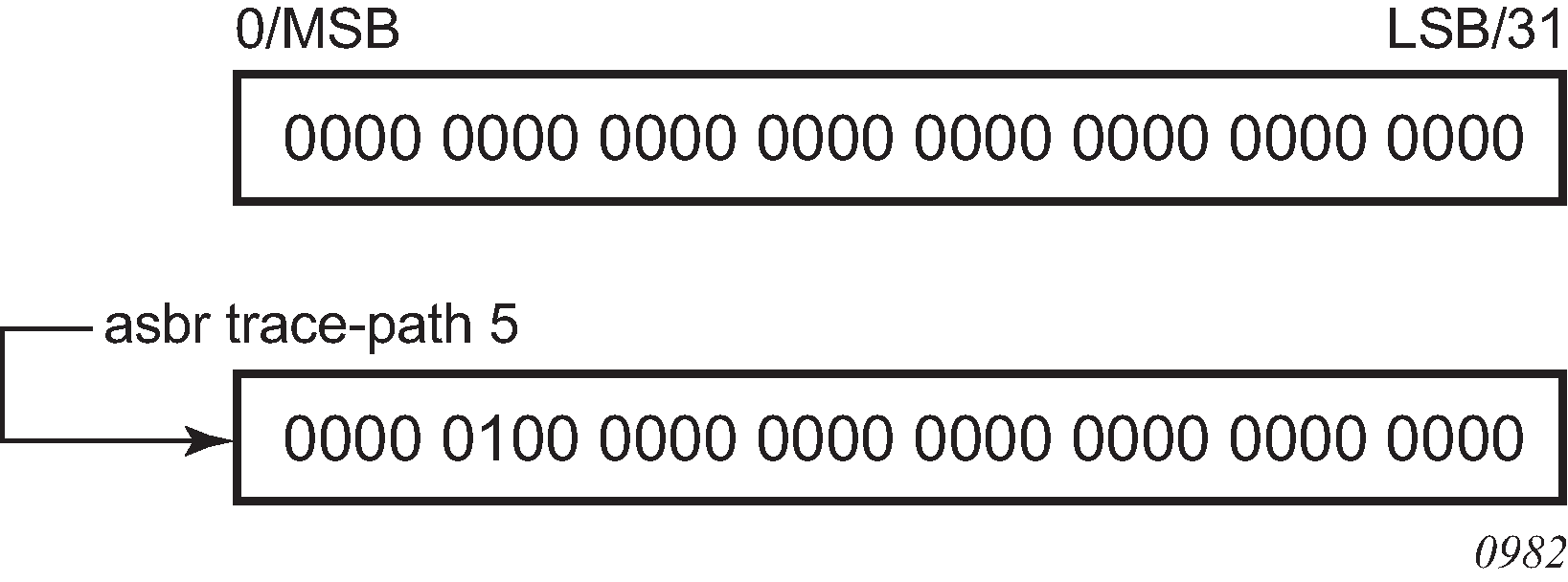
Domain IDs are incompatible with any other use of normal tags. The domain ID should be configured with a value between 1 and 31 by each router in a specific OSPF domain (OSPF instance).
When an external route is originated by an ASBR using an internal OSPF route in a specific domain, the corresponding bit (1 to 31) is set in the AS-external LSA.
The no form of this command removes the ASBR status and withdraws the routes redistributed from the routing table into OSPF from the link-state database.
Default
no asbr
Parameters
- domain-id
Specifies the domain ID.
compatible-rfc1583
Syntax
[no] compatible-rfc1583
Context
config>router>ospf
Platforms
Supported on all 7210 SAS platforms as described in this document
Description
This command enables OSPF summary and external route calculations in compliance with RFC 1583 and earlier RFCs.
RFC 1583 and earlier RFCs use a different method to calculate summary and external route costs. To avoid routing loops, all routers in an OSPF domain should perform the same calculation method.
Although it would be favorable to require all routers to run a more current compliancy level, this command allows the router to use obsolete methods of calculation.
The no form of this command enables the post-RFC 1583 method of summary and external route calculation.
Default
compatible-rfc1583
disable-ldp-sync
Syntax
[no] disable-ldp-sync
Context
config>router>ospf
Platforms
Supported on all 7210 SAS platforms as described in this document
Description
This command disables the IGP-LDP synchronization feature on all interfaces participating in the OSPF routing protocol. When this command is executed, IGP immediately advertises the actual value of the link cost for all interfaces that have the IGP-LDP synchronization enabled if the currently advertised cost is different. It will disable IGP-LDP synchronization for all interfaces. This command does not delete the interface configuration.
For information about LDP synchronization, see ‟IGP-LDP and static route-LDP Synchronization on the 7210 SAS-K 2F6C4T and 7210 SAS-K 3SFP+ 8C” and the ldp-sync and ldp-sync-timer commands in the 7210 SAS-D, Dxp, K 2F1C2T, K 2F6C4T, K 3SFP+ 8C Router Configuration Guide.
The no form of this command restores the default settings and re-enables IGP-LDP synchronization on all interfaces participating in the OSPF routing protocol and for which the ldp-sync-timer is configured.
Default
no disable-ldp-sync
export
Syntax
export policy-name [policy-name…(5 maximum)]
no export
Context
config>router>ospf
config>router>ospf3
Platforms
Supported on all 7210 SAS platforms as described in this document
Description
This command associates export route policies to determine which routes are exported from the route table to OSPF or OSPFv3. Export polices are only in effect if OSPF or OSPFv3 is configured as an ASBR.
If no export policy is specified, non-OSPF or OSPFv3 routes are not exported from the routing table manager to OSPF or OSPFv3.
If multiple policy names are specified, the policies are evaluated in the order they are specified. The first policy that matches is applied. If multiple export commands are issued, the last command entered will override the previous command. A maximum of five policy names can be specified.
The no form of this command removes all policies from the configuration.
Default
no export
Parameters
- policy-name
Specifies the export route policy name (the soecified name must already be defined). Allowed values are any string up to 32 characters composed of printable, 7-bit ASCII characters. If the string contains special characters (such #, $, spaces), the entire string must be enclosed within double quotes.
export-limit
Syntax
export-limit number [log percentage]
no export-limit
Context
config>router>ospf
config>router>ospf3
Platforms
Supported on all 7210 SAS platforms as described in this document
Description
This command configures the maximum number of routes (prefixes) that can be exported into OSPF or OSPFv3 from the route table.
The no form of this command removes the parameters from the configuration.
Default
no export-limit
Parameters
- number
Specifies the maximum number of routes (prefixes) that can be exported into OSPF or OSPFv3 from the route table.
- log percentage
Specifies the percentage of the export-limit, at which a warning log message and SNMP notification would be sent.
external-db-overflow
Syntax
external-db-overflow limit seconds
no external-db-overflow
Context
config>router>ospf
config>router>ospf3
Platforms
Supported on all 7210 SAS platforms as described in this document
Description
This command configures limits on the number of non-default AS-external LSA entries that can be stored in the link-state database (LSDB) and specifies a wait timer before processing these entries after the limit is exceeded.
The limit value specifies the maximum number of non-default AS-external LSA entries that can be stored in the LSDB. Placing a limit on the non-default AS-external LSAs in the LSDB protects the router from receiving an excessive number of external routes that consume excessive memory or CPU resources. If the number of routes reaches or exceeds the configured limit, the table is in an overflow state. When in an overflow state, the router will not originate any new AS-external LSAs and will withdraws all the self-originated non-default external LSAs.
The seconds value specifies the amount of time to wait after an overflow state before regenerating and processing non-default AS-external LSAs. The waiting period acts like a dampening period preventing the router from continuously running Shortest Path First (SPF) calculations caused by the excessive number of non-default AS-external LSAs.
The external-db-overflow command must be set identically on all routers attached to any regular OSPF or OSPFv3 area. OSPF or OSPFv3 stub areas and not-so-stubby areas (NSSAs) are excluded.
The no form of this command disables limiting the number of non-default AS-external LSA entries.
Default
no external-db-overflow
Parameters
- limit
Specifies the maximum number of non-default AS-external LSA entries that can be stored in the LSDB before going into an overflow state expressed as a decimal integer.
- interval
Specifies the number of seconds after entering an overflow state before attempting to process non-default AS-external LSAs, expressed as a decimal integer.
external-preference
Syntax
external-preference preference
no external-preference
Context
config>router>ospf
config>router>ospf3
Platforms
Supported on all 7210 SAS platforms as described in this document
Description
This command configures the preference for OSPF or OSPFv3 external routes.
A route can be learned by the router from different protocols, in which case, the costs are not comparable. When this occurs the preference is used to decide which route will be used.
Different protocols should not be configured with the same preference, if this occurs the tiebreaker is determined by the default preference as defined in the Route preference defaults by route type. If multiple routes are learned with an identical preference using the same protocol, the lowest cost route is used.
The no form of this command reverts to the default value.
Default
150
Parameters
- preference
Specifies the preference for external routes expressed as a decimal integer. Defaults for different route types are listed in the following table.
Table 5. Route preference defaults by route type Route type
Preference
Configurable
Direct attached
0
No
Static routes
5
Yes
OSPF/ OSPFv3 internal
10
Yes
IS-IS level 1 internal
15
Yes
IS-IS level 2 internal
18
Yes
OSPF/OSPFv3 external
150
Yes
IS-IS level 1 external
160
Yes
IS-IS level 2 external
165
Yes
BGP
170
Yes
Note:Preference for OSPF or OSPFv3 internal routes is configured with the preference command.
graceful-restart
Syntax
[no] graceful-restart
Context
config>router>ospf
config>router>ospf3
Platforms
Supported on all 7210 SAS platforms as described in this document
Description
This command enables graceful-restart for OSPF or OSPFv3. When the control plane of a GR-capable router fails, the neighboring routers (GR helpers) temporarily preserve adjacency information, so packets continue to be forwarded through the failed GR router using the last known routes. If the control plane of the GR router comes back up within the GR timer, the routing protocols reconverges to minimize service interruption.
The no form of this command disables graceful restart and removes all graceful restart configurations in the OSPF or OSPFv3 instance.
Default
no graceful-restart
helper-disable
Syntax
[no] helper-disable
Context
config>router>ospf>graceful-restart
config>router>ospf3>graceful-restart
Platforms
Supported on all 7210 SAS platforms as described in this document
Description
This command disables the helper support for graceful restart.
When graceful-restart is enabled, the router can be a helper (meaning that the router is helping a neighbor to restart) or be a restarting router or both. The router supports only helper mode. This facilitates the graceful restart of neighbors but will not act as a restarting router.
The no form of this command enables helper support and is the default when graceful-restart is enabled.
Default
helper-disable
import
Syntax
import [policy-name…(up to 15 max)]
no import policy-name
Context
config>router>ospf3
Platforms
Supported on all 7210 SAS platforms as described in this document
Description
This command specifies the import route policy for an OSPF3 instance.
The no form of this command removes the policy association with the OSPF3 instance.
Default
no import
Parameters
- policy-name
Specifies the export route policy name (the soecified name must already be defined). Allowed values are any string up to 32 characters composed of printable, 7-bit ASCII characters. If the string contains special characters (such #, $, spaces), the entire string must be enclosed within double quotes.
loopfree-alternate
Syntax
loopfree-alternate [remote-lfa]
loopfree-alternate remote-lfa [max-pq-cost value]
no loopfree-alternate
Context
config>router>ospf
Platforms
Supported on all 7210 SAS platforms as described in this document
Description
This command enables Loop-Free Alternate (LFA) computation by SPF for the OSPF routing protocol instance.
This command instructs the IGP SPF to precompute both a primary next hop and an LFA next hop for every learned prefix. When found, the LFA next hop is populated into the routing table along with the primary next-hop for the prefix.
The remote LFA next hop calculation by the IGP LFA SPF is enabled by using the remote-lfa option. When this option is enabled in an IGP instance, SPF performs the remote LFA additional computation following the regular LFA next-hop calculation when the latter results in no protection for one or more prefixes that are resolved to a specific interface.
Remote LFA extends the protection coverage of LFA-FRR to any topology by automatically computing and establishing or tearing down shortcut tunnels, also referred to as repair tunnels, to a remote LFA node. Doing this puts the packets back into the shortest path without looping them back to the node that forwarded them over the repair tunnel. The remote LFA node is referred to as a PQ node. A repair tunnel can, in theory, be an RSVP LSP, an LDP-in-LDP tunnel, or a segment routing tunnel. Using segment routing repair tunnels is restricted to the remote LFA node.
The remote LFA algorithm is a per-link LFA SPF calculation and is not per-prefix, like the regular LFA calculation. It provides protection to all destination prefixes that share the protected link by using the neighbor on the other side of the protected link as a proxy for those prefixes.
Default
no loopfree-alternate
Parameters
- remote-lfa
Keyword to enable the remote LFA next-hop calculation by the IGP LFA SPF.
- value
Specifies the maximum IGP cost from the router that is performing the remote LFA calculation to the candidate P or Q node.
loopfree-alternate-exclude
Syntax
loopfree-alternate-exclude prefix-policy prefix-policy [prefix-policy ... (up to 5)]
no loopfree-alternate-exclude
Context
config>router>ospf
Platforms
Supported on all 7210 SAS platforms as described in this document
Description
This command excludes from LFA SPF calculation prefixes that match a prefix entry or a tag entry in a prefix policy.
The implementation already allows the user to exclude an interface in IS-IS or OSPF, an OSPF area, or an IS-IS level from the LFA SPF.
If a prefix is excluded from LFA, then it will not be included in LFA calculation regardless of its priority. The prefix tag will, however, be used in the main SPF. Note that prefix tags are defined for the IS-IS protocol but not for the OSPF protocol.
The default action of the loopfree-alternate-exclude command, when not explicitly specified by the user in the prefix policy, is a ‟reject”. Therefore, regardless if the user did or did not explicitly add the statement ‟default-action reject” to the prefix policy, a prefix that did not match any entry in the policy will be accepted into LFA SPF.
The no form of this command deletes the exclude prefix policy.
Parameters
- prefix-policy
Specifies the name of the prefix policy. The specified name must have been previously defined. 32 characters maximum.
overload
Syntax
overload [timeout seconds]
no overload
Context
config>router>ospf
config>router>ospf3
Platforms
Supported on all 7210 SAS platforms as described in this document
Description
This command changes the overload state of the local router so that it appears to be overloaded. When overload is enabled, the router can participate in OSPF or OSPFv3 routing, but is not used for transit traffic. Traffic destined to directly attached interfaces continues to reach the router.
To put the IGP in an overload state, enter a timeout value. The IGP will enter the overload state until the timeout timer expires or a no overload command is executed.
If the overload command is encountered during the execution of an overload-on-boot command, this command takes precedence. This could occur as a result of a saved configuration file where both parameters are saved. When the file is saved by the system the overload-on-boot command is saved after the overload command. However, if overload-on-boot is configured under OSPF or OSPFv3 with no timeout value configured, the router will remain in overload state indefinitely after a reboot.
The no form of this command reverts to the default. When the no overload command is executed, the overload state is terminated regardless of the reason the protocol entered overload state.
Default
no overload
Parameters
- timeout seconds
Specifies the number of seconds to reset overloading.
overload-include-stub
Syntax
[no] overload-include-stub
Context
config>router>ospf
config>router>ospf3
Platforms
Supported on all 7210 SAS platforms as described in this document
Description
This command determines whether the OSPF or OSPFv3 stub networks should be advertised with a maximum metric value when the system goes into overload state for any reason. When enabled, the system uses the maximum metric value. When this command is enabled and the router is in overload, all stub interfaces, including loopback and system interfaces, will be advertised at the maximum metric.
Default
no overload-include-stub
overload-on-boot
Syntax
overload-on-boot [timeout seconds]
no overload
Context
config>router>ospf
config>router>ospf3
Platforms
Supported on all 7210 SAS platforms as described in this document
Description
This command configures the IGP upon bootup in the overload state until one of the following events occurs:
the timeout timer expires.
a manual override of the current overload state is entered with the no overload command.
When the router is in an overload state, the router is used only if there is no other router to reach the destination. The no overload command does not affect the overload-on-boot function.
The no form of this command removes the overload-on-boot function from the configuration.
Parameters
- timeout seconds
Specifies the number of seconds to reset overloading.
preference
Syntax
preference preference
no preference
Context
config>router>ospf
config>router>ospf3
Platforms
Supported on all 7210 SAS platforms as described in this document
Description
This command configures the preference for OSPF or OSPFv3 internal routes.
A route can be learned by the router from different protocols, in which case, the costs are not comparable. When this occurs, the preference is used to decide which route will be used.
Different protocols should not be configured with the same preference. If this occurs, the tiebreaker is based on the default preference as defined in Route preference defaults by route type. If multiple routes are learned with an identical preference using the same protocol, the lowest cost route is used.
The no form of this command reverts to the default value.
Default
preference 10
Parameters
- preference
Specifies the preference for internal routes, expressed as a decimal integer.
reference-bandwidth
Syntax
reference-bandwidth reference-bandwidth
reference-bandwidth [tbps Tera-bps] [gbps Giga-bps] [mbps Mega-bps] [kbps Kilo-bps]
no reference-bandwidth
Context
config>router>ospf
config>router>ospf3
Platforms
Supported on all 7210 SAS platforms as described in this document
Description
This command configures the reference bandwidth used to calculate the default costs of interfaces based on their underlying link speed.
The default interface cost is calculated as follows:
cost = reference-bandwidth bandwidth
The default reference-bandwidth is 100,000,000 Kb/s or 100 Gb/s, so the default auto-cost metrics for various link speeds are as follows:
10 Mb/s link default cost of 10000
100 Mb/s link default cost of 1000
1 Gb/s link default cost of 100
10 Gb/s link default cost of 10
The reference-bandwidth command assigns a default cost to the interface based on the interface speed. To override this default cost on a particular interface, use the metric metric command in the config>router>ospf>area>interface context.
The no form of this command reverts to the default value.
Default
reference-bandwidth 100000000
Parameters
- bandwidth-in-kbps
Specifies the reference bandwidth in kilobits per second, expressed as a decimal integer.
- Tera-bps
Specifies the reference bandwidth in terabits per second, expressed as a decimal integer.
- Giga-bps
Specifies the reference bandwidth in gigabits per second, expressed as a decimal integer.
- Mega-bps
Specifies the reference bandwidth in megabits per second, expressed as a decimal integer.
- Kilo-bps
Specifies the reference bandwidth in kilobits per second, expressed as a decimal integer.
router-id
Syntax
router-id ip-address
no router-id
Context
config>router>ospf
config>router>osp3
Platforms
Supported on all 7210 SAS platforms as described in this document
Description
This command configures the router ID for the OSPF or OSPFv3 instance.
When configuring the router ID in the base instance of OSPF or OSPFv3, it overrides the router ID configured in the config>router context.
The default value for the base instance is inherited from the configuration in the config>router context. If the router ID in the config>router context is not configured, the following applies.
The system uses the system interface address (which is also the loopback address).
If a system interface address is not configured, use the last 32 bits of the chassis MAC address.
When configuring a new router ID, the instance is not automatically restarted with the new router ID. The next time the instance is initialized, the new router ID is used.
To force the new router ID to be used, issue the shutdown and no shutdown commands for the instance, or reboot the entire router.
The no form of this command reverts to the default value.
Default
router-id 0.0.0.0
Parameters
- ip-address
Specifies a 32-bit unsigned integer uniquely identifying the router in the Autonomous System.
timers
Syntax
timers
Context
config>router>ospf
config>router>ospf3
Platforms
Supported on all 7210 SAS platforms as described in this document
Description
Commands in this context configure OSPF or OSPFv3 timers. Timers control the delay between receipt of an LSA requiring a Dijkstra (Shortest Path First (SPF)) calculation and the minimum time between successive SPF calculations.
Changing the timers affects CPU utilization and network reconvergence times. Lower values reduce the convergence time but increase CPU utilization. Higher values reduce CPU utilization but increase the reconvergence time.
lsa-arrival
Syntax
lsa-arrival lsa-arrival-time
no lsa-arrival
Context
config>router>ospf>timers
config>router>ospf3>timers
Platforms
Supported on all 7210 SAS platforms as described in this document
Description
This command defines the minimum delay that must pass between receipt of the same LSAs arriving from neighbors.
Nokia recommends that the neighbor configured lsa-generate lsa-second-wait interval is equal or greater than the lsa-arrival timer configured here.
The no form of this command reverts to the default value.
Default
no lsa-arrival
Parameters
- lsa-arrival-time
Specifies the timer, in milliseconds. Values entered that do not match this requirement are rejected.
lsa-generate
Syntax
lsa-generate max-lsa-wait [lsa-initial-wait [lsa-second-wait]]
no lsa-generate-interval
Context
config>router>ospf>timers
config>router>ospf3>timers
Platforms
Supported on all 7210 SAS platforms as described in this document
Description
This command customizes the throttling of OSPF or OSPFv3 LSA generation. Timers that determine when to generate the first, second, and subsequent LSAs can be controlled with this command. Subsequent LSAs are generated at increasing intervals of the lsa-second-wait timer until a maximum value is reached.
Configuring the lsa-arrival interval to equal or less than the lsa-second-wait interval configured in the lsa-generate command is recommended.
The no form of this command reverts to the default value.
Default
no lsa-generate
Parameters
- max-lsa-wait
Specifies the maximum interval, in milliseconds, between two consecutive ocurrences of an LSA being generated
- lsa-initial-wait
Specifies the first waiting period between LSA originates, in milliseconds. When the LSA exceeds the lsa-initial-wait timer value and the topology changes, there is no wait period and the LSA is immediately generated.
When an LSA is generated, the initial wait period commences. If within the specified lsa-initial-wait period and another topology change occurs, the lsa-initial-wait timer applies.
- lsa-second-wait
Specifies the hold time in milliseconds between the first and second LSA generation. The next topology change is subject to this second wait period. With each subsequent topology change, the wait time doubles (this is 2x the previous wait time.). This assumes that each failure occurs within the relevant wait period.
spf-wait
Syntax
spf-wait max-spf-wait [spf-initial-wait [spf-second-wait]]
no spf-wait
Context
config>router>ospf>timers
config>router>ospf3>timers
Platforms
Supported on all 7210 SAS platforms as described in this document
Description
This command defines the maximum interval between two consecutive SPF calculations in milliseconds. Timers that determine when to initiate the first, second, and subsequent SPF calculations after a topology change occurs can be controlled with this command. Subsequent SPF runs (if required) will occur at exponentially increasing intervals of the spf-second-wait interval. For example, if the spf-second-wait interval is 1000, the next SPF will run after 2000 milliseconds, and then next SPF will run after 4000 milliseconds, and so on, until it reaches the spf-wait value. The SPF interval will stay at the spf-wait value until there are no more SPF runs scheduled in that interval. After a full interval without any SPF runs, the SPF interval will drop back to the spf-initial-wait value.
The timer must be entered in increments of 100 milliseconds. Values entered that do not match this requirement will be rejected.
The no form of this command reverts to the default value.
Default
no spf-wait
Parameters
- max-spf-wait
Specifies the maximum interval, in milliseconds, between two consecutive SPF calculations.
- spf-initial-wait
Specifies the initial SPF calculation delay, in milliseconds, after a topology change.
- spf-second-wait
Specifies the hold time, in milliseconds, between the first and second SPF calculation.
segment-routing
Syntax
segment-routing
no segment-routing
Context
config>router>ospf
Platforms
Supported on all 7210 SAS platforms as described in this document
Description
Commands in this context configure segment routing parameters within an IGP instance.
Segment routing adds to OSPF routing protocols the ability to perform shortest path routing and source routing using the concept of the abstract segment. A segment can represent a local prefix of a node, a specific adjacency of the node (interface or next-hop), a service context, or a specific explicit path over the network. For each segment, the IGP advertises an identifier referred to as a segment ID (SID).
When segment routing is used together with the MPLS data plane, the SID is a standard MPLS label. A router forwarding a packet using segment routing pushes one or more MPLS labels.
Segment routing using MPLS labels is used in both shortest path routing applications and traffic engineering applications. This command configures the shortest path forwarding application.
After segment routing is configured in the OSPF instance, the router performs the following operations.
Advertises the segment routing capability sub-TLV to routers in all areas and levels of this IGP instance. However, only neighbors with which it established an adjacency will interpret the SID and label range information and use it for calculating the label to swap to or push for a given resolved prefix SID.
Advertises the assigned index for each configured node SID in the new prefix SID sub-TLV with the N-flag (node-SID flag) set. The segment routing module then programs the incoming label map (ILM) with a pop operation for each local node SID in the data path.
Automatically assigns and advertises an adjacency SID label for each formed adjacency over a network IP interface in the new adjacency SID sub-TLV. The segment routing module programs the ILM with a pop operation (in effect with a swap to an implicit null label operation), for each advertised adjacency SID.
Resolves received prefixes, and if a prefix SID sub-TLV exists, the segment routing module programs the ILM with a swap operation and an LTN with a push operation both pointing to the primary/LFA NHLFE. An SR tunnel is also added to the TTM.
When the user enables segment routing in an IGP instance, the main SPF and LFA SPF are computed, and the primary next-hop and LFA backup next-hop for a received prefix are added to the RTM without the label information advertised in the prefix SID sub-TLV.
The no form of this command reverts to the default value.
prefix-sid-range
Syntax
prefix-sid-range {global | start-label label-value max-index index-value}
no prefix-sid-range
Context
config>router>ospf>segment-routing
Platforms
Supported on all 7210 SAS platforms as described in this document
Description
This command configures the prefix SID index range and offset label value for an IGP instance.
The user must configure the prefix SID index range and the offset label value that this IGP instance uses. Because each prefix SID represents a network global IP address, the SID index for a prefix must be unique in the network. Therefore, all routers in the network are expected to configure and advertise the same prefix SID index range for an IGP instance. However, the label value used by each router to represent this prefix, that is, the label programmed in the ILM, can be local to that router by the use of an offset label, referred to as a start label, as in the following:
Local Label (Prefix SID) = start-label + {SID index}
The label operation in the network becomes similar to LDP when operating in the independent label distribution mode (RFC 5036), with the difference that the label value used to forward a packet to each downstream router is computed by the upstream router based on the advertised prefix SID index using the preceding formula.
There are two mutually exclusive modes of operation for the prefix SID range on the router. In the global mode of operation, the user configures the global value and this IGP instance assumes the start label value is the lowest label value in the SRGB and the prefix SID index range size equal to the range size of the SRGB. When one IGP instance selects the global option for the prefix SID range, all IGP instances on the system are restricted to do the same. The user must shut down the segment routing context and delete the prefix-sid-range command in all IGP instances to change the SRGB. After the SRGB is changed, the user must re-enter the prefix-sid-range command. The SRGB range change fails if an already allocated SID index or label goes out of range.
In the per-instance mode of operation, the user partitions the SRGB into non-overlapping sub-ranges among the IGP instances. The user therefore configures a subset of the SRGB by specifying the start label value and the prefix SID index range size. All resulting net label values (start-label + index) must be within the SRGB or the configuration fails.
The code checks for overlaps of the resulting net label value range across IGP instances and strictly enforces that these ranges do not overlap. The user must shut down the segment routing context of an IGP instance to change the SID index or label range of that IGP instance using the prefix-sid-range command.
In addition, any range change will fail if an already allocated SID index or label goes out of range. The user can, however, change the SRGB on the fly as long as it does not reduce the current per-IGP instance SID index or label range defined in the prefix-sid-range command. Otherwise, the user must shut down the segment routing context of the IGP instance and delete and reconfigure the prefix-sid-range command.
The no form of this command reverts to the default value.
Default
no prefix-sid-range
Parameters
- start-label label-value
Specifies the label offset for the SR label range of this IGP instance.
- max-index index-value
Specifies the maximum value of the prefix SID index range for this IGP instance.
- global
Keyword to enable global operation mode.
tunnel-mtu
Syntax
tunnel-mtu bytes
no tunnel-mtu
Context
config>router>ospf>segment-routing
Platforms
Supported on all 7210 SAS platforms as described in this document
Description
This command configures the maximum transmission unit (MTU) of all SR tunnels within each IGP instance.
The MTU of an SR tunnel populated into the TTM is determined like in the case of an IGP tunnel; for example, LDP LSP, based on the outgoing interface MTU minus the label stack size. Remote LFA can add at least two more labels to the tunnel for a total of three labels. There is no default value. If the user does not configure an SR tunnel MTU, the MTU is determined by IGP.
The MTU of the SR tunnel in bytes is determined as follows:
SR_Tunnel_MTU = MIN {Cfg_SR_MTU, IGP_Tunnel_MTU- (1+ frr-overhead)*4}
Where:
Cfg_SR_MTU is the MTU configured by the user for all SR tunnels within a specific IGP instance using this command. If no value was configured by the user, the SR tunnel MTU will be determined by the following IGP interface calculation.
IGP_Tunnel_MTU is the minimum of the IS-IS or OSPF interface MTU among all the ECMP paths or among the primary and LFA backup paths of this SR tunnel.
frr-overhead is set to 1 if segment-routing and remote-lfa options are enabled in the IGP instance. Otherwise, it is set to 0.
The SR tunnel MTU is dynamically updated whenever any of the preceding parameters used in its calculation changes. This includes when the set of tunnel next hops changes, or the user changes the configured SR MTU or interface MTU value.
The no form of this command reverts to the default value.
Default
no tunnel-mtu
Parameters
- bytes
Specifies the size of the MTU in bytes.
tunnel-table-pref
Syntax
tunnel-table-pref preference
no tunnel-table-pref
Context
config>router>ospf>segment-routing
Platforms
Supported on all 7210 SAS platforms as described in this document
Description
This command configures the TTM preference of shortest path SR tunnels created by the IGP instance. The TMM preference is used in the case of VPRN auto-bind or BGP transport tunnels when the new tunnel binding commands are configured to the any value, which parses the TTM for tunnels in the protocol preference order. The user can either use the global TTM preference or list the tunnel types they want to use. When they list the tunnel types explicitly, the TTM preference is used to select one type over the other. In both cases, a fallback to the next preferred tunnel type is performed if the selected one fails. Also, a reversion to a more preferred tunnel type is performed as soon as one is available.
The segment routing module adds an SR tunnel entry to the TTM for each resolved remote node SID prefix and programs the datapath with the corresponding LTN with the push operation pointing to the primary and LFA backup NHLFEs.
The default preference for shortest path SR tunnels in the TTM is set lower than LDP tunnels but higher than BGP tunnels to allow controlled migration of customers without disrupting their current deployment when they enable segment routing. The following is the setting of the default preference for various tunnel types. This includes the preference of SR tunnels based on the shortest path (referred to as SR-OSPF).
The global default TTM preference for the tunnel types is as follows:
ROUTE_PREF_RSVP 7
ROUTE_PREF_SR_TE 8
ROUTE_PREF_LDP 9
ROUTE_PREF_OSPF_TTM 10
ROUTE_PREF_ISIS_TTM 11
ROUTE_PREF_BGP_TTM 12
ROUTE_PREF_GRE 255
The default value for SR-OSPF is the same regardless of whether one or more OSPF instances programmed a tunnel for the same prefix. The selection of an SR tunnel in this case is based on the lowest IGP instance ID.
The no form of this command reverts to the default value.
Default
no tunnel-table-pref
Parameters
- preference
Specifies the integer value to represent the preference of OSPF SR tunnels in the TTM.
traffic-engineering
Syntax
[no] traffic-engineering
Context
config>router>ospf
Platforms
Supported on all 7210 SAS platforms as described in this document
Description
This command enables traffic engineering route calculations constrained by nodes or links.
Traffic engineering enables the router to perform route calculations constrained by nodes or links. The traffic engineering capabilities of this router are limited to calculations based on link and nodal constraints.
The no form of this command disables traffic-engineered route calculations.
Default
no traffic-engineering
OSPF area commands
area
Syntax
[no] area area-id
Context
config>router>ospf
config>router>ospf3
Platforms
Supported on all 7210 SAS platforms as described in this document
Description
This command configures an OSPF or OSPF3 area. An area is a collection of network segments within an AS that have been administratively grouped together. The area ID can be specified in dotted decimal notation or as a 32-bit decimal integer.
The no form of this command deletes the specified area from the configuration. Deleting the area also removes the OSPF or OSPF3 configuration of all the interfaces, virtual-links, and address-ranges that are currently assigned to this area.
Default
no area
Parameters
- area-id
Specifies the OSPF or OSPF3 area ID expressed in dotted decimal notation or as a 32-bit decimal integer.
area-range
Syntax
area-range ipv4-prefix/mask | ipv6-prefix/prefix-length [advertise | not-advertise]
no area-range ipv4-prefix/mask | ipv6-prefix/prefix-length
Context
config>router>ospf>area
config>router>ospf>area>nssa
config>router>ospf3>area
config>router>ospf3>area>nssa
Platforms
Supported on all 7210 SAS platforms as described in this document
Description
This command creates ranges of addresses on an Area Border Router (ABR) for the purpose of route summarization or suppression. When a range is created, the range is configured to be advertised or not advertised into other areas. Multiple range commands may be used to summarize or hide different ranges. In the case of overlapping ranges, the most specific range command applies.
ABRs send summary link advertisements to describe routes to other areas. To minimize the number of advertisements that are flooded, you can summarize a range of IP addresses and send reachability information about these addresses in an LSA.
The no form of this command deletes the range advertisement or non-advertisement.
Default
no area-range
Special Cases
- NSSA Context
Specifies that the range applies to external routes (via type-7 LSAs) learned within the NSSA when the routes are advertised to other areas as type-5 LSAs.
- Area Context
If this command is not entered under the NSSA context, the range applies to summary LSAs even if the area is an NSSA
Parameters
- ipv4-prefix/mask
Specifies the IPv4 prefix for the range in dotted-decimal notation and the subnet mask for the range, expressed as a decimal integer.
- ipv6-prefix/prefix-length
Specifies the IPv6 prefix for the range in hexadecimal notation, and the prefix length for the range, expressed as a decimal integer.
- advertise | not-advertise
Specifies whether to advertise the summarized range of addresses to other areas.
blackhole-aggregate
Syntax
[no] blackhole-aggregate
Context
config>router>ospf>area
config>router>ospf3>area
Platforms
Supported on all 7210 SAS platforms as described in this document
Description
This command installs a low priority blackhole route for the entire aggregate. Exisiting routes that make up the aggregate will have a higher priority and only the components of the range for which no route exists are blackholed.
It is possible that when performing area aggregation, addresses may be included in the range for which no actual route exists. This can cause routing loops. To avoid this problem, configure the blackhole-aggregate option.
The no form of this command removes this option.
Default
blackhole-aggregate
default-metric
Syntax
default-metric metric
no default-metric
Context
config>router>ospf>area>stub
config>router>ospf3>area>stub
Platforms
Supported on all 7210 SAS platforms as described in this document
Description
This command configures the metric used by the area border router (ABR) for the default route into a stub area.
The default metric should only be configured on an ABR of a stub area.
An ABR generates a default route if the area is a stub area.
The no form of this command reverts to the default value.
Default
default-metric 1
Parameters
- metric
Specifies the metric, expressed as a decimal integer, for the default route cost to be advertised into the stub area.
key-rollover-interval
Syntax
key-rollover-interval seconds
no key-rollover-interval
Context
config>router>ospf3>area
Platforms
Supported on all 7210 SAS platforms as described in this document
Description
This command configures the key rollover interval.
The no form of this command resets the configured interval to the default setting.
Default
key-rollover-interval 10
Parameters
- seconds
Specifies the time, in seconds, after which a key rollover will start.
nssa
Syntax
[no] nssa
Context
config>router>ospf>area
config>router>ospf3>area
Platforms
Supported on all 7210 SAS platforms as described in this document
Description
Commands in this context configure an OSPF or OSPFv3 NSSA and adds or removes the NSSA designation from the area.
NSSAs are similar to stub areas in that no external routes are imported into the area from other OSPF areas. The major difference between a stub area and an NSSA is that an NSSA has the capability to flood external routes that it learns throughout its area and via an ABR to the entire OSPF or OSPFv3 domain.
Existing virtual links of a non-stub area or NSSA area are removed when the designation is changed to NSSA or stub.
An area can be designated as stub or NSSA, but never both at the same time.
By default, an area is not configured as an NSSA area.
The no form of this command removes the NSSA designation and configuration context from the area.
Default
no nssa
originate-default-route
Syntax
originate-default-route [type-7]
originate-default-route [type-nssa]
no originate-default-route
Context
config>router>ospf>area>nssa
config>router>ospf3>area>nssa
Platforms
Supported on all 7210 SAS platforms as described in this document
Description
This command enables the generation of a default route and its LSA type into an NSSA by an NSSA ABR or ASBR.
The functionality of the type-7 parameter and the type-nssa parameter is the same. The type-7 parameter is available in the ospf context; the type-nssa parameter is available in the ospf3 context. Include the type-7 or type-nssa parameter to inject a type 7 LSA default route instead of the type 3 LSA into the NSSA configured with no summaries.
To revert to a type 3 LSA, enter the originate-default-route command without the type-7 or type-nssa parameter.
When configuring an NSSA with no summaries, the ABR will inject a type 3 LSA default route into the NSSA area. Some older implementations expect a type 7 LSA default route.
The no form of this command disables origination of a default route.
Default
no originate-default-route
Parameters
- type-7 | type-nssa
Specifies that a type 7 LSA or type NSSA should be used for the default route.
redistribute-external
Syntax
[no] redistribute-external
Context
config>router>ospf>area>nssa
config>router>ospf3>area>nssa
Platforms
Supported on all 7210 SAS platforms as described in this document
Description
This command enables the redistribution of external routes into the NSSA or an NSSA ABR that is exporting the routes into non-NSSA areas.
NSSAs are similar to stub areas in that no external routes are imported into the area from other OSPF or OSPFv3 areas. The major difference between a stub area and an NSSA is that the NSSA has the capability to flood external routes that it learns (provided it is an ASBR) throughout its area and via an Area Border Router to the entire OSPF or OSPFv3 domain.
The no form of this command disables the default behavior to automatically redistribute external routes into the NSSA area from the NSSA ABR.
Default
redistribute-external
stub
Syntax
[no] stub
Context
config>router>ospf>area
config>router>ospf3>area
Platforms
Supported on all 7210 SAS platforms as described in this document
Description
Commands in this context configure an OSPF or OSPF3 stub area and adds or removes the stub designation from the area.
External routing information is not flooded into stub areas. All routers in the stub area must be configured with the stub command. An OSPF or OSPF3 area cannot be both an NSSA and a stub area.
Existing virtual links of a non-stub or NSSA area will be removed when its designation is changed to NSSA or stub.
By default, an area is not a stub area.
The no form of this command removes the stub designation and configuration context from the area.
Default
no stub
summaries
Syntax
[no] summaries
Context
config>router>ospf>area>nssa
config>router>ospf>area>stub
config>router>ospf3>area>nssa
config>router>ospf3>area>stub
Platforms
Supported on all 7210 SAS platforms as described in this document
Description
This command enables sending summary (type 3) advertisements into a stub area or NSSA on an ABR.
This parameter is particularly useful to reduce the size of the routing and link-state database (LSDB) tables within the stub or NSSA area.
By default, summary route advertisements are sent into the stub area or NSSA.
The no form of this command disables sending summary route advertisements and, for stub areas, only the default route is advertised by the ABR.
Default
summaries
Interface/virtual link commands
authentication
Syntax
authentication bidirectional sa-name
authentication [inbound sa-name outbound sa-name]
no authentication
Context
config>router>ospf3>area>interface
config>router>ospf3>area>virtual-link
Platforms
Supported on all 7210 SAS platforms as described in this document
Description
This command configures an interface with a static security association (SA) used to authenticate OSPFv3 packets.
The no form of this command removes the SA name from the configuration.
Default
no authentication
Parameters
- bidirectional sa-name
Specifies the IPSec SA name, up to 32 characters, used for transmitting and receiving OSPFv3 packets.
- inbound sa-name
Specifies the IPSec SA name, up to 32 characters, used for receiving OSPFv3 packets.
- outbound sa-name
Specifies the IPSec SA name, up to 32 characters, used for transmitting OSPFv3 packets.
authentication-key
Syntax
authentication-key [authentication-key | hash-key] [hash | hash2]
no authentication-key
Context
config>router>ospf>area>interface
config>router>ospf3>area>virtual-link
Platforms
Supported on all 7210 SAS platforms as described in this document
Description
This command configures the password used by the OSPF or OSPFv3 interface or virtual-link to send and receive OSPF or OSPFv3 protocol packets on the interface when simple password authentication is configured.
All neighboring routers must use the same type of authentication and password for proper protocol communication. If the authentication-type is configured as password, this key must be configured.
By default, no authentication key is configured.
The no form of this command removes the authentication key.
Default
no authentication-key
Parameters
- authentication-key
Specifies the authentication key. The key can be any combination of ASCII characters up to 8 characters (unencrypted). If spaces are used in the string, enclose the entire string in quotation marks (‟ ”).
- hash-key
Specifies the hash key. The key can be any combination of ASCII characters up to 22 characters (encrypted). If spaces are used in the string, enclose the entire string in quotation marks (‟ ”). This is useful when a user must configure the parameter, but, for security purposes, the actual unencrypted key value is not provided.
- hash
Specifies the key is entered in an encrypted form. If the hash parameter is not used, the key is assumed to be in a non-encrypted, clear text form. For security, all keys are stored in encrypted form in the configuration file with the hash parameter specified.
- hash2
Specifies the key is entered in a more complex encrypted form. If the hash2 parameter is not used, the less encrypted hash form is assumed.
authentication-type
Syntax
authentication-type {password | message-digest}
no authentication-type
Context
config>router>ospf>area>interface
config>router>ospf3>area>virtual-link
Platforms
Supported on all 7210 SAS platforms as described in this document
Description
This command enables authentication and specifies the type of authentication to be used on the OSPF or OSPFv3 interface.
Both password and message-digest authentication are supported.
By default, authentication is not enabled on an interface.
The no form of this command disables authentication on the interface.
Default
no authentication
Parameters
- password
Keyword to enable simple password (plain text) authentication. If authentication is enabled and no authentication type is specified in the command, simple password authentication is enabled.
- message-digest
Keyword to enable message digest MD5 authentication in accordance with RFC1321. If this option is configured, at least one message digest key must be configured.
bfd-enable
Syntax
[no] bfd-enable [remain-down-on-failure]
Context
config>router>ospf>area>interface
Platforms
Supported on all 7210 SAS platforms as described in this document
Description
This command enables the use of bidirectional forwarding (BFD) to control the state of the associated OSPF interface. By enabling BFD on an OSPF interface, the state of the interface is tied to the state of the BFD session between the local node and the remote node.
The optional remain-down-on-failure parameter can be specified on OSPF interfaces that are enabled for BFD to keep OSPF from reaching the full state if the BFD session to that neighbor cannot be established. This option is disabled by default and should be used only if there is a chance that unicast packets might be discarded while multicast packets are forwarded.
The no form of this command removes BFD from the associated OSPF adjacency.
Default
no bfd-enable
dead-interval
Syntax
dead-interval seconds
no dead-interval
Context
config>router>ospf>area>interface
config>router>ospf>area>virtual-link
config>router>ospf3>area>interface
config>router>ospf3>area>virtual-link
Platforms
Supported on all 7210 SAS platforms as described in this document
Description
This command configures the time, in seconds, that OSPF or OSPFv3 waits before declaring a neighbor router down. If no hello packets are received from a neighbor for the duration of the dead interval, the router is assumed to be down. The minimum interval must be two times the hello interval.
The no form of this command reverts to the default value.
Default
dead-interval 40
Special Cases
- OSPF or OSPFv3 Interface
If the dead-interval configured applies to an interface, all nodes on the subnet must have the same dead interval.
- Virtual Link
If the dead-interval configured applies to a virtual link, the interval on both termination points of the virtual link must have the same dead interval.
Parameters
- seconds
Specifies the dead interval, in seconds, expressed as a decimal integer.
export
Syntax
[no] export policy-name [policy-name...(up to 5 max)]
Context
config>router>ospf
Platforms
Supported on all 7210 SAS platforms as described in this document
Description
This command configures export routing policies that determine the routes exported from the routing table to OSPF.
If multiple policy names are specified, the policies are evaluated in the order they are specified. The first policy that matches is applied. If multiple export commands are issued, the last command entered overrides the previous command. A maximum of five policy names can be specified.
If an aggregate command is also configured in the config>router context, the aggregation is applied before the export policy is applied.
Routing policies are created in the config>router>policy-options context.
The no form of this command removes the specified policy-name or all policies from the configuration if no policy-name is specified.
Default
no export
Parameters
- policy-name
Specifies the export policy name. Up to five policy-name arguments can be specified.
export-limit
Syntax
export-limit number [log percentage]
no export-limit
Context
config>router>ospf
Platforms
Supported on all 7210 SAS platforms as described in this document
Description
This command configures the maximum number of routes (prefixes) that can be exported into OSPF from the route table.
The no form of this command removes the parameters from the configuration.
Default
no export-limit
Parameters
- number
Specifies the maximum number of routes (prefixes) that can be exported into OSPF from the route table.
- percentage
Specifies the percentage of the export-limit, at which a warning log message and SNMP notification would be sent.
hello-interval
Syntax
hello-interval seconds
no hello-interval
Context
config>router>ospf>area>interface
config>router>ospf>area>virtual-link
config>router>ospf3>area>interface
config>router>ospf3>area>virtual-link
Platforms
Supported on all 7210 SAS platforms as described in this document
Description
This command configures the interval between OSPF or OSPFv3 hellos issued on the interface or virtual link.
The hello-interval, in combination with the dead-interval, is used to establish and maintain the adjacency. Use this parameter to edit the frequency that hello packets are sent.
Reducing the interval, in combination with an appropriate reduction in the associated dead-interval, allows for faster detection of link or router failures at the cost of higher processing costs.
The no form of this command reverts to the default value.
Default
hello-interval 10
Special Cases
- OSPF Interface
If the hello-interval configured applies to an interface, all nodes on the subnet must have the same hello interval.
- Virtual Link
If the hello-interval configured applies to a virtual link, the interval on both termination points of the virtual link must have the same hello interval.
Parameters
- seconds
Specifies the hello interval, in seconds, expressed as a decimal integer.
interface
Syntax
[no] interface ip-int-name [secondary]
Context
config>router>ospf>area
config>router>ospf3>area
Platforms
Supported on all 7210 SAS platforms as described in this document
Description
This command configures an OSPF or OSPFv3 interface.
By default, interfaces are not activated in any interior gateway protocol, such as OSPF or OSPFv3, unless explicitly configured.
The no form of this command deletes the OSPF interface configuration for this interface. The shutdown command in the config>router>ospf>interface context can be used to disable an interface without removing the configuration for the interface.
Default
no interface
Parameters
- ip-int-name
Specifies the IP interface name. Interface names must be unique within the group of defined IP interfaces for the config>router>interface command. An interface name cannot be in the form of an IP address. Interface names can be any string up to 32 characters composed of printable, 7-bit ASCII characters. If the string contains special characters (#, $, spaces, and so on), the entire string must be enclosed within double quotess.
If the IP interface name does not exist or does not have an IP address configured, an error message will be returned.
If the IP interface exists in a different area it will be moved to this area.
- secondary
Keyword to enable multiple secondary adjacencies to be established over a single IP interface.
interface-type
Syntax
interface-type {broadcast | point-to-point}
no interface-type
Context
config>router>ospf>area>interface
config>router>ospf3>area>interface
Platforms
Supported on all 7210 SAS platforms as described in this document
Description
This command configures the interface type to be either broadcast or point-to-point.
Use this command to set the interface type of an Ethernet link to point-to-point to avoid having to carry the broadcast adjacency maintenance overhead of the Ethernet link provided the link is used as a point-to-point.
If the interface type is not known at the time the interface is added to OSPF or OSPFv3, and subsequently the IP interface is bound (or moved) to a different interface type, this command must be entered manually.
The no form of this command reverts to the default value.
Default
interface-type broadcast (if the physical interface is Ethernet or unknown)
Special Cases
- Virtual-Link
A virtual link is always regarded as a point-to-point interface and not configurable.
Parameters
- broadcast
Keyword to configure the interface to maintain this link as a broadcast network. To significantly improve adjacency forming and network convergence, a network should be configured as point-to-point if only two routers are connected, even if the network is a broadcast media such as Ethernet.
- point-to-point
Keyword to configure the interface to maintain this link as a point-to-point link.
loopfree-alternate-exclude
Syntax
[no] loopfree-alternate-exclude
Context
config>router>ospf>area>interface
config>router>ospf3>area>interface
Platforms
Supported on all 7210 SAS platforms as described in this document
Description
This command instructs IGP to exclude a specific interface or all interfaces that are participating in a specific IS-IS level or OSPF area in the SPF LFA computation. This reduces LFA SPF calculation where it is not needed.
When an interface is excluded from the LFA SPF in IS-IS, it is excluded in both level 1 and level 2. When it is excluded from the LFA SPF in OSPF, it is excluded in all areas. However, the loopfree-alternate-exclude command can only be executed under the area in which the specified interface is primary. If the command is enabled, the interface is excluded in that area and in all other areas where the interface is secondary. If the user attempts to apply it to an area where the interface is secondary, the command will fail.
The no form of this command reinstates the default value.
Default
no loopfree-alternate-exclude
message-digest-key
Syntax
message-digest-key keyid md5 [key | hash-key] [hash| hash2]
no message-digest-key keyid
Context
config>router>ospf>area>interface
Platforms
Supported on all 7210 SAS platforms as described in this document
Description
This command configures a message digest key when MD5 authentication is enabled on the interface. Multiple message digest keys can be configured.
The no form of this command removes the message digest key identified by the key-id.
Default
no message-digest-key
Parameters
- key-id
Specifies the message digest key, expressed as a decimal integer.
- md5 key
Specifies the MD5 key. The key can be any alphanumeric string up to 16 characters.
- md5 hash-key
Specifies the MD5 hash key. The key can be any combination of ASCII characters up to 32 characters (encrypted). If spaces are used in the string, enclose the entire string in quotation marks (‟ ”).
This is useful when a user must configure the parameter, but, for security purposes, the actual unencrypted key value is not provided.
- hash
Specifies the key is entered in an encrypted form. If the hash parameter is not used, the key is assumed to be in a non-encrypted, clear text form. For security, all keys are stored in encrypted form in the configuration file with the hash parameter specified.
- hash2
Specifies the key is entered in a more complex encrypted form. If the hash2 parameter is not used, the less encrypted hash form is assumed.
metric
Syntax
metric metric
no metric
Context
config>router>ospf>area>interface
config>router>ospf3>area>interface
Platforms
Supported on all 7210 SAS platforms as described in this document
Description
This command configures an explicit route cost metric for the OSPF or OSPFv3 interface that overrides the metrics calculated based on the speed of the underlying link.
The no form of this command deletes the manually configured interface metric, so the interface uses the computed metric based on the reference-bandwidth command setting and the speed of the underlying link.
Default
no metric
Parameters
- metric
Specifies the metric to be applied to the interface, expressed as a decimal integer.
mtu
Syntax
mtu bytes
no mtu
Context
config>router>ospf>area>interface
config>router>ospf3>area>interface
Platforms
Supported on all 7210 SAS platforms as described in this document
Description
This command configures the OSPF or OSPFv3 interface MTU value used when negotiating an OSPF or OSPFv3 adjacency.
The operational OSPF or OSPFv3 MTU value is calculated as follows.
If this command is not configured, the OSPF or OSPFv3 interface operational MTU derives the MTU value from the IP interface MTU (which is derived from the port MTU); for example, port MTU minus 14 bytes for a null-encapsulated Ethernet port for OSPF (not OSPFv3). If the derived MTU value is less than 576 bytes, the OSPF interface operational MTU is set to 576 bytes. If a lower interface MTU is required, it must be explicitly configured using this command.
If this command is configured for OSPF (not OSPFv3):
-
if the OSPF interface MTU is less than 576 bytes, it becomes the operational OSPF MTU, regardless of the port MTU value
-
if the OSPF interface MTU is equal to or greater than 576 bytes, and the derived interface MTU is less than 576 bytes, the operational OSPF MTU is set to 576 bytes
-
if the OSPF interface MTU is equal to or greater than 576 bytes, and the derived interface MTU is greater than 576 bytes, the operational OSPF MTU is set to the lesser of the values configured with this command and the derived MTU
The port MTU must be set to 512 bytes or higher, because OSPF cannot support port MTU values lower than 512 bytes.
If this command is configured for OSPFv3:
the operational OSPFv3 MTU is set to the lesser of the values configured with this command and the derived MTU
this applies only when the port MTU is set to 1280 bytes or higher, because OSPFv3 cannot support port MTU values less than 1280 bytes
To determine the actual packet size, add 14 bytes for an Ethernet packet and 18 bytes for a tagged Ethernet packet to the size of the OSPF or OSPFv3 (IP) packet MTU configured with this command.
If this command is configured to a value less than the interface or port MTU value, the OSPF or OSPFv3 MTU value will be used to transmit OSPF packets.
The no form of this command uses the value derived from the MTU configured in the config>port context.
Default
no mtu
Parameters
- bytes
Specifies the MTU to be used by OSPF or OSPFv3 for this logical interface, in byte.
node-sid
Syntax
node-sid index value
node-sid label value
no node-sid
Context
config>router>ospf>area>interface
Platforms
Supported on all 7210 SAS platforms as described in this document
Description
This command assigns a node SID index or label value to the prefix representing the primary address of an IPv4 network interface of type loopback. Only a single node SID can be assigned to an interface. The secondary address of an IPv4 interface cannot be assigned a node SID index and does not inherit the SID of the primary IPv4 address.
This command fails if the network interface is not of type loopback or if the interface is defined in an IES or a VPRN context. Also, assigning the same SID index or label value to the same interface in two different IGP instances is not allowed within the same node.
The value of the label or index SID is taken from the range configured for this IGP instance. When using the global mode of operation, a new segment routing module checks that the same index or label value cannot be assigned to more than one loopback interface address. When using the per-instance mode of operation, this check is not required because the index and label ranges of the various IGP instance are not allowed to overlap.
The no form of this command reverts to the default value.
Default
no node-sid
Parameters
- value
Specifies the node SID index or label value.
passive
Syntax
[no] passive
Context
config>router>ospf>area>interface
config>router>ospf3>area>interface
Platforms
Supported on all 7210 SAS platforms as described in this document
Description
This command adds the passive property to the OSPF or OSPFv3 interface where passive interfaces are advertised as OSPF or OSPFv3 interfaces but do not run the OSPF or OSPFv3 protocol.
By default, only interface addresses that are configured for OSPF or OSPFv3 will be advertised as OSPF or OSPFv3 interfaces. The passive parameter allows an interface to be advertised as an OSPF or OSPFv3 interface without running the OSPF or OSPFv3 protocol.
While in passive mode, the interface will ignore ingress OSPF or OSPFv3 protocol packets and not transmit any OSPF or OSPFv3 protocol packets.
The no form of this command removes the passive property from the OSPF or OSPFv3 interface.
Default
no passive
priority
Syntax
priority number
no priority
Context
config>router>ospf>area>interface
config>router>ospf3>area>interface
Platforms
Supported on all 7210 SAS platforms as described in this document
Description
This command configures the priority of the OSPF or OSPFv3 interface that is used in an election of the designated router on the subnet.
This parameter is only used if the interface is of type broadcast. The router with the highest priority interface becomes the designated router. A router with priority 0 is not eligible to be the designated router or backup designated touter.
The no form of this command reverts the interface priority to the default value.
Default
priority 1
Parameters
- number
Specifies the interface priority, expressed as a decimal integer.
retransmit-interval
Syntax
retransmit-interval seconds
no retransmit-interval
Context
config>router>ospf>area>interface
config>router>ospf>area>virtual-link
config>router>ospf3>area>interface
Platforms
Supported on all 7210 SAS platforms as described in this document
Description
This command specifies the length of time that OSPF or OSPFv3 will wait before retransmitting an unacknowledged link state advertisement (LSA) to an OSPF neighbor.
The value should be longer than the expected round trip delay between any two routers on the attached network. When the retransmit interval expires and no acknowledgement has been received, the LSA will be retransmitted.
The no form of this command reverts to the default interval.
Default
retransmit-interval 5
Parameters
- seconds
Specifies the retransmit interval, in seconds, expressed as a decimal integer.
transit-delay
Syntax
transit-delay seconds
no transit-delay
Context
config>router>ospf>area>interface
config>router>ospf>area>virtual-link
config>router>ospf3>area>interface
config>router>ospf3>area>virtual-link
Platforms
Supported on all 7210 SAS platforms as described in this document
Description
This command configures the estimated time, in seconds, that it takes to transmit an LSA on the interface or virtual link.
The no form of this command reverts to the default delay time
Default
transit-delay 1
Parameters
- seconds
Specifies the transit delay, in seconds, expressed as a decimal integer.
virtual-link
Syntax
[no] virtual-link router-id transit-area area-id
Context
config>router>ospf>area
config>router>ospf3>area
Platforms
Supported on all 7210 SAS platforms as described in this document
Description
This command configures a virtual link to connect area border routers to the backbone through a virtual link.
The backbone area (area 0.0.0.0) must be contiguous and all other areas must be connected to the backbone area. If it is not practical to connect an area to the backbone, the area border routers must be connected via a virtual link. The two area border routers will form a point-to-point like adjacency across the transit area. A virtual link can only be configured while in the area 0.0.0.0 context.
The router-id specified in this command must be associated with the virtual neighbor. The transit area cannot be a stub area or a NSSA.
The no form of this command deletes the virtual link.
Default
no virtual-link
Parameters
- router-id
Specifies the router ID of the virtual neighbor in IP address dotted decimal notation.
- transit-area area-id
Specifies the area ID specified identifies the transit area that links the backbone area to the area that has no physical connection with the backbone, expressed in dotted decimal notation or as a 32-bit decimal integer.
Show commands
ospf
Syntax
ospf
Context
show>router
Platforms
Supported on all 7210 SAS platforms as described in this document
Description
Commands in this context display OSPF information.
ospf3
Syntax
ospf
Context
show>router
Platforms
Supported on all 7210 SAS platforms as described in this document
Description
Commands in this context display OSPFv3 information.
area
Syntax
area [area-id] [detail]
Context
show>router>ospf
show>router>ospf3
Platforms
Supported on all 7210 SAS platforms as described in this document
Description
This command displays configuration information about all areas or the specified area. When detail is specified, operational and statistical information will be displayed.
Parameters
- area-id
Specifies the OSPF area ID expressed in dotted decimal notation or as a 32-bit decimal integer.
- detail
Displays detailed information about the area.
Output
The following output is an example of area information, and Output fields: OSPF area describes the output fields.
Sample outputA:7210# show router ospf area detail
===============================================================================
OSPF Areas (Detailed)
===============================================================================
-------------------------------------------------------------------------------
Area Id: 0.0.0.0
-------------------------------------------------------------------------------
Area Id : 0.0.0.0 Type : Standard
Virtual Links : 0 Total Nbrs : 2
Active IFs : 3 Total IFs : 3
Area Bdr Rtrs : 0 AS Bdr Rtrs : 0
SPF Runs : 7 Last SPF Run : 10/26/2006 10:09:18
Router LSAs : 3 Network LSAs : 3
Summary LSAs : 0 Asbr-summ LSAs : 0
Nssa ext LSAs : 0 Area opaque LSAs : 3
Total LSAs : 9 LSA Cksum Sum : 0x28b62
Blackhole Range : True Unknown LSAs : 0
===============================================================================
*A:Bombadil# show router ospf area 0.0.0.0 detail
===============================================================================
OSPF Area (Detailed) : 0.0.0.0
===============================================================================
-------------------------------------------------------------------------------
Configuration
-------------------------------------------------------------------------------
Area Id : 0.0.0.0 Type : Standard
-------------------------------------------------------------------------------
Statistics
-------------------------------------------------------------------------------
Virtual Links : 0 Total Nbrs : 2
Active IFs : 3 Total IFs : 3
Area Bdr Rtrs : 0 AS Bdr Rtrs : 0
SPF Runs : 7 Last SPF Run : 10/26/2006 10:09:18
Router LSAs : 3 Network LSAs : 3
Summary LSAs : 0 Asbr-summ LSAs : 0
Nssa ext LSAs : 0 Area opaque LSAs : 3
Total LSAs : 9 LSA Cksum Sum : 0x28b62
Blackhole Range : True Unknown LSAs : 0
===============================================================================
Label |
Description |
|---|---|
Area Id |
Displays a 32 bit integer uniquely identifying an area |
Type |
NSSA — This area is configured as an NSSA area Standard — This area is configured as a standard area (not NSSA or stub) Stub — This area is configured as a stub area |
SPF Runs |
Displays the number of times that the intra-area route table has been calculated using this area link-state database |
LSA Count |
Displays the total number of link-state advertisements in this area link-state database, excluding AS external LSAs |
LSA Cksum Sum |
Displays the 32-bit unsigned sum of the link-state database advertisements LS checksums contained in this area link-state database. This checksum excludes AS external LSAs (type-5). |
No. of OSPF Areas |
Displays the number of areas configured on the router |
Virtual Links |
Displays the number of virtual links configured through this transit area |
Active IFs |
Displays the active number of interfaces configured in this area |
Area Bdr Rtrs |
Displays the total number of ABRs reachable within this area |
AS Bdr Rtrs |
Displays the total number of ASBRs reachable within this area |
Last SPF Run |
Displays the time when the last intra-area SPF was run on this area |
Router LSAs |
Displays the total number of router LSAs in this area |
Network LSAs |
Displays the total number of network LSAs in this area |
Summary LSAs |
Displays the summary of LSAs in this area |
Asbr-summ LSAs |
Displays the summary of ASBR LSAs in this area |
Nssa-ext LSAs |
Displays the total number of NSSA-EXT LSAs in this area |
Area opaque LSAs |
Displays the total number of opaque LSAs in this area |
Total Nbrs |
Displays the total number of neighbors in this area |
Total IFs |
Displays the total number of interfaces configured in this area |
Total LSAs |
Displays the sum of LSAs in this area excluding autonomous system external LSAs |
Blackhole Range |
False — No blackhole route is installed for aggregates configured in this area |
database
Syntax
database [type {router | network | summary | asbr-summary | external | nssa | all}] [area area-id] [adv-router router-id] [link-state-id] [detail]
Context
show>router>ospf
show>router>ospf3
Platforms
Supported on all 7210 SAS platforms as described in this document
Description
This command displays information about the OSPF or OSPFv3 LSDB.
When no command line options are specified, the command displays brief output for all database entries.
Parameters
- type
Specifies to filter the OSPF or OSPFv3 LSDB information based on which type is specified of the following types: router, network, summary, asbr-summary, external, nssa, all.
- type router
Displays only router (Type 1) LSAs in the LSDB.
- type network
Displays only network (Type 2) LSAs in the LSDB.
- type summary
Displays only summary (Type 3) LSAs in the LSDB.
- type asbr-summary
Displays only ASBR summary (Type 4) LSAs in the LSDB.
- type external
Displays only AS external (Type 5) LSAs in the LSDB. External LSAs are maintained globally and not per area. If the display of external links is requested, the area parameter, if present, is ignored.
- type nssa
Displays only NSSA area-specific AS external (Type 7) LSAs in the LSDB.
- type all
Displays all LSAs in the LSDB. The all keyword is intended to be used with either the area area-id or the adv-router router-id [link-state-id] parameters.
- area area-id
Displays LSDB information associated with the specified OSPF area ID.
- adv-router router-id [link-state-id]
Displays LSDB information associated with the specified advertising router. To further narrow the number of items displayed, the link-state-id can optionally be specified.
- detail
Displays detailed information about the LSDB entries.
Output
The following output is an example of database information, and Output fields: OSPF database describes the output fields.
Sample outputA:ALA-A# show router ospf database
===============================================================================
OSPF Link State Database (Type : All)
===============================================================================
Area Id Type Link State Id Adv Rtr Id Age Sequence Cksum
-------------------------------------------------------------------------------
0.0.0.0 Router 180.0.0.2 180.0.0.2 1800 0x800000b6 0xf54
0.0.0.0 Router 180.0.0.5 180.0.0.5 1902 0x8000009d 0xcb7c
0.0.0.0 Router 180.0.0.8 180.0.0.8 1815 0x8000009a 0x529b
0.0.0.0 Router 180.0.0.9 180.0.0.9 1156 0x80000085 0xd00f
0.0.0.0 Router 180.0.0.10 180.0.0.10 533 0x8000009d 0x3f1f
0.0.0.0 Router 180.0.0.11 180.0.0.11 137 0x80000086 0xc58f
0.0.0.0 Router 180.0.0.12 180.0.0.12 918 0x8000009d 0x4cf3
0.0.0.0 Router 180.0.0.13 180.0.0.13 1401 0x800000a2 0x879c
0.0.0.0 Network 180.0.53.28 180.0.0.28 149 0x80000083 0xe5cd
0.0.0.0 Network 180.0.54.28 180.0.0.28 1259 0x80000083 0xdad7
0.0.0.0 Summary 180.0.0.15 180.0.0.10 378 0x80000084 0xeba1
0.0.0.0 Summary 180.0.0.15 180.0.0.12 73 0x80000084 0xdfab
0.0.0.0 Summary 180.0.0.18 180.0.0.10 1177 0x80000083 0xcfbb
0.0.0.1 Summary 180.100.25.4 180.0.0.12 208 0x80000091 0x3049
0.0.0.1 AS Summ 180.0.0.8 180.0.0.10 824 0x80000084 0x3d07
0.0.0.1 AS Summ 180.0.0.8 180.0.0.12 1183 0x80000095 0x4bdf
0.0.0.1 AS Summ 180.0.0.9 180.0.0.10 244 0x80000082 0x73cb
n/a AS Ext 7.1.0.0 180.0.0.23 1312 0x80000083 0x45e7
n/a AS Ext 7.2.0.0 180.0.0.23 997 0x80000082 0x45e6
n/a AS Ext 10.20.0.0 180.0.0.23 238 0x80000081 0x2d81
...
-------------------------------------------------------------------------------
No. of LSAs: 339
===============================================================================
A:ALA-A#
A:ALA-A# show router ospf database detail
===============================================================================
OSPF Link State Database (Type : All) (Detailed)
-------------------------------------------------------------------------------
Router LSA for Area 0.0.0.0
-------------------------------------------------------------------------------
Area Id : 0.0.0.0 Adv Router Id : 180.0.0.2
Link State Id : 180.0.0.2 LSA Type : Router
Sequence No : 0x800000b7 Checksum : 0xd55
Age : 155 Length : 192
Options : E
Flags : None Link Count : 14
Link Type (1) : Point To Point
Nbr Rtr Id (1) : 180.0.0.13 I/F Address (1) : 180.0.22.2
No of TOS (1) : 0 Metric-0 (1) : 25
Link Type (2) : Stub Network
Network (2) : 180.0.22.0 Mask (2) : 255.255.255.0
No of TOS (2) : 0 Metric-0 (2) : 25
Link Type (3) : Point To Point
Nbr Rtr Id (3) : 180.0.0.12 I/F Address (3) : 180.0.5.2
No of TOS (3) : 0 Metric-0 (3) : 25
Link Type (4) : Stub Network
Network (4) : 180.0.5.0 Mask (4) : 255.255.255.0
No of TOS (4) : 0 Metric-0 (4) : 25
Link Type (5) : Point To Point
Nbr Rtr Id (5) : 180.0.0.8 I/F Address (5) : 180.0.13.2
No of TOS (5) : 0 Metric-0 (5) : 6
Link Type (6) : Stub Network
Network (6) : 180.0.13.0 Mask (6) : 255.255.255.0
No of TOS (6) : 0 Metric-0 (6) : 6
Link Type (7) : Point To Point
Nbr Rtr Id (7) : 180.0.0.5 I/F Address (7) : 180.0.14.2
No of TOS (7) : 0 Metric-0 (7) : 6
Link Type (8) : Stub Network
Network (8) : 180.0.14.0 Mask (8) : 255.255.255.0
No of TOS (8) : 0 Metric-0 (8) : 6
Link Type (9) : Point To Point
Nbr Rtr Id (9) : 180.0.0.11 I/F Address (9) : 180.0.17.2
No of TOS (9) : 0 Metric-0 (9) : 25
Link Type (10) : Stub Network
Network (10) : 180.0.17.0 Mask (10) : 255.255.255.0
No of TOS (10) : 0 Metric-0 (10) : 25
Link Type (11) : Stub Network
Network (11) : 180.0.0.2 Mask (11) : 255.255.255.255
No of TOS (11) : 0 Metric-0 (11) : 1
Link Type (12) : Stub Network
Network (12) : 180.0.18.0 Mask (12) : 255.255.255.0
No of TOS (12) : 0 Metric-0 (12) : 24
Link Type (13) : Point To Point
Nbr Rtr Id (13) : 180.0.0.10 I/F Address (13) : 180.0.3.2
No of TOS (13) : 0 Metric-0 (13) : 25
Link Type (14) : Stub Network
Network (14) : 180.0.3.0 Mask (14) : 255.255.255.0
No of TOS (14) : 0 Metric-0 (14) : 25
-------------------------------------------------------------------------------
AS Ext LSA for Network 180.0.0.14
-------------------------------------------------------------------------------
Area Id : N/A Adv Router Id : 180.0.0.10
Link State Id : 180.0.0.14 LSA Type : AS Ext
Sequence No : 0x80000083 Checksum : 0xa659
Age : 2033 Length : 36
Options : E
Network Mask : 255.255.255.255 Fwding Address : 180.1.6.15
Metric Type : Type 2 Metric-0 : 4
Ext Route Tag : 0
-------------------------------------------------------------------------------
...
A:ALA-A#
Label |
Description |
|---|---|
Area Id |
Displays the OSPF area identifier |
Type LSA Type |
Router — router LSA type (OSPF) Network — network LSA type (OSPF) Summary — summary LSA type (OSPF) ASBR Summary — ASBR summary LSA type (OSPF) Nssa-ext — LSA area-specific, NSSA external (OSPF) Area opaque — area opaque LSA type (OSPF) |
Link State Id |
Displays the link-state ID. The link-state ID is an LSA type specific field containing either a number to distinguish several LSAs from the same router, an interface ID, or a router-id; it identifies the piece of the routing domain being described by the advertisement. |
Adv Rtr Id Adv Router Id |
Displays the router identifier of the router advertising the LSA |
Age |
Displays the age of the link state advertisement in seconds |
Sequence Sequence No |
Displays the signed 32-bit integer sequence number |
Cksum Checksum |
Displays the 32-bit unsigned sum of the link-state advertisements LS checksums |
No. of LSAs |
Displays the number of LSAs displayed |
Options |
EA — External attribute LSA support DC — Demand circuit support R — If clear, a node can participates in OSPF topology distribution without being used to forward transit traffic N — Type 7 LSA support E — External routes support |
Prefix Options |
P — Propagate NSSA LSA |
Flags |
None — No flags set V — The router is an endpoint for one or more fully adjacent virtual links having the described area as the transit area E — The router is an AS boundary router B — The router is an area border router |
Link Count |
Displays the number of links advertised in the LSA |
Link Type (n) |
Displays the link type of the nth link in the LSA |
Network (n) |
Displays the network address of the nth link in the LSA |
Metric-0 (n) |
Displays the cost metric of the nth link in the LSA |
interface
Syntax
interface [ip-int-name | ip-address] [detail]
interface [area area-id] [detail]
Context
show>router>ospf
show>router>ospf3
Platforms
Supported on all 7210 SAS platforms as described in this document
Description
This command displays the details of the OSPF or OSPFv3 interface, this interface can be identified by IP address or IP interface name. When neither is specified, all in-service interfaces are displayed.
The detail option produces a great amount of data. Nokia recommends to detail only when requesting a specific interface.
Parameters
- ip-addr
Displays only the interface identified by this IP address.
- ip-int-name
Displays only the interface identified by this interface name, up to 32 characters.
- area area-id
Displays all interfaces configured in this area.
- detail
Displays detailed information about the interfaced.
Output
The following outputs are examples of OSPF interface information. The associated tables describe the output fields.
Standard output: Sample output, Output fields: OSPF interface
Detailed output: Sample output — detailed, Output fields: OSPF interface detail
*A:JC-NodeA# show router ospf interface area detail
===============================================================================
OSPF Interfaces in Area (Detailed) : 1
===============================================================================
Interface : ip-10.10.1.1
-------------------------------------------------------------------------------
IP Address       : 10.10.1.1
Area Id          : 0.0.0.1              Priority         : 1
Hello Intrvl     : 5 sec                Rtr Dead Intrvl  : 15 sec
Retrans Intrvl   : 5 sec                Poll Intrvl      : 120 sec
Cfg Metric       : 0                    Advert Subnet    : True
Transit Delay    : 1                    Auth Type        : None
Passive          : False                Cfg MTU          : 0
Admin Status     : Enabled              Oper State       : Designated Rtr
Designated Rtr   : 10.20.1.1            Backup Desig Rtr : 0.0.0.0
IF Type          : Broadcast            Network Type     : Transit
Oper MTU         : 1500                 Last Enabled     : 04/11/2007 16:06:27
Oper Metric      : 1000
Nbr Count        : 0                    If Events        : 5
Tot Rx Packets   : 0                    Tot Tx Packets   : 1116
Rx Hellos        : 0                    Tx Hellos        : 1116
Rx DBDs          : 0                    Tx DBDs          : 0
Rx LSRs          : 0                    Tx LSRs          : 0
Rx LSUs          : 0                    Tx LSUs          : 0
Rx LS Acks       : 0                    Tx LS Acks       : 0
Retransmits      : 0                    Discards         : 0
Bad Networks     : 0                    Bad Virt Links   : 0
Bad Areas        : 0                    Bad Dest Addrs   : 0
Bad Auth Types   : 0                    Auth Failures    : 0
Bad Neighbors    : 0                    Bad Pkt Types    : 0
Bad Lengths      : 0                    Bad Hello Int.   : 0
Bad Dead Int.    : 0                    Bad Options      : 0
Bad Versions     : 0                    Bad Checksums    : 0
LSA Count        : 0                    LSA Checksum     : 0x0
TE Metric        : 678
===============================================================================
*A:JC-NodeA#
Label |
Description |
|---|---|
If Name |
Displays the interface name |
Area Id |
Displays a 32-bit integer uniquely identifying the area to which this interface is connected. Area ID 0.0.0.0 is used for the OSPF backbone. |
D Rtr Id |
Displays the IP interface address of the router identified as the designated router for the network in which this interface is configured. Set to 0.0.0.0 if there is no Designated router. |
BD Rtr Id |
The IP interface address of the router identified as the backup designated router for the network in which this interface is configured. Set to 0.0.0.0 if there is no backup designated router. |
Adm |
Dn — OSPF on this interface is administratively shut down Up — OSPF on this interface is administratively enabled |
Opr |
Down — This is the initial interface state. In this state, the lower-level protocols have indicated that the interface is unusable. Wait — The router is trying to determine the identity of the (Backup) designated router for the network PToP — The interface is operational, and connects either to a physical point-to-point network or to a virtual link DR — This router is the designated router for this network BDR — This router is the backup designated router for this network ODR — The interface is operational and part of a broadcast or NBMA network on which another router has been selected to be the designated router |
No. of OSPF Interfaces |
Displays the number of interfaces listed |
A:SetupCLI# show router ospf interface detail
===============================================================================
OSPF Interfaces (Detailed)
-------------------------------------------------------------------------------
Interface : system
-------------------------------------------------------------------------------
IP Address       : 10.1.255.255
Area Id          : 0.0.0.0              Priority         : 1
Hello Intrvl     : 10 sec               Rtr Dead Intrvl  : 40 sec
Retrans Intrvl   : 5 sec                Poll Intrvl      : 120 sec
Cfg Metric       : 0                    Advert Subnet    : True
Transit Delay    : 1                    Auth Type        : None
Passive          : True  Cfg MTU          : 0
Admin Status     : Enabled              Oper State       : Designated Rtr
Designated Rtr   : 2.2.2.2              Backup Desig Rtr : 0.0.0.0
IF Type          : Broadcast            Network Type     : Transit
Oper MTU         : 1500                 Last Enabled     : 05/14/2006 09:16:26
Oper Metric      : 0
Nbr Count        : 0                    If Events        : 5
Tot Rx Packets   : 0                    Tot Tx Packets   : 0
Rx Hellos        : 0                    Tx Hellos        : 0
Rx DBDs          : 0                    Tx DBDs          : 0
Rx LSRs          : 0                    Tx LSRs          : 0
Rx LSUs          : 0                    Tx LSUs          : 0
Rx LS Acks       : 0                    Tx LS Acks       : 0
Retransmits      : 0                    Discards         : 0
Bad Networks     : 0                    Bad Virt Links   : 0
Bad Areas        : 0                    Bad Dest Addrs   : 0
Bad Auth Types   : 0                    Auth Failures    : 0
Bad Neighbors    : 0                    Bad Pkt Types    : 0
Bad Lengths      : 0                    Bad Hello Int.   : 0
Bad Dead Int.    : 0                    Bad Options      : 0
Bad Versions     : 0                    Bad Checksums    : 0
LSA Count        : 0                    LSA Checksum     : 0x0
-------------------------------------------------------------------------------
Interface : sender
-------------------------------------------------------------------------------
IP Address       : 10.1.1.1
Area Id          : 0.0.0.0              Priority         : 1
Hello Intrvl     : 10 sec               Rtr Dead Intrvl  : 40 sec
Retrans Intrvl   : 5 sec                Poll Intrvl      : 120 sec
Cfg Metric       : 0                    Advert Subnet    : True
Transit Delay    : 1                    Auth Type        : None
Passive          : False                Cfg MTU          : 0
===============================================================================
A:SetupCLI#
Label |
Description |
|---|---|
Interface |
Displays the IP address of this OSPF interface |
IP Address |
Displays the IP address and mask of this OSPF interface |
Interface Name |
Displays the interface name |
Area Id |
Displays a 32-bit integer uniquely identifying the area to which this interface is connected. Area ID 0.0.0.0 is used for the OSPF backbone. |
Priority |
Displays the priority of this interface. Used in multi-access networks, this field is used in the designated router election algorithm. |
Hello Intrvl |
Displays the length of time, in seconds, between the Hello packets that the router sends on the interface. This value must be the same for all routers attached to a common network. |
Rtr Dead Intrvl |
Displays the number of seconds that router Hello packets have not been seen before its neighbors declare the router down. This should be some multiple of the Hello interval. This value must be the same for all routers attached to a common network. |
Retrans Intrvl |
Displays the number of seconds between link-state advertisement retransmissions, for adjacencies belonging to this interface. This value is also used when retransmitting database description and link-state request packets. |
Poll Intrvl |
Displays the larger time interval, in seconds, between the Hello packets sent to an inactive non-broadcast multi-access neighbor |
Metric |
Displays the metric to be advertised for this interface |
Advert Subnet |
False — When a point-to-point interface is configured as false, then the subnet is not advertised and the endpoints are advertised as host routes True — When a point-to-point interface is configured to true, then the subnet is advertised |
Transit Delay |
Displays the estimated number of seconds it takes to transmit a link state update packet over this interface |
Auth Type |
Displays the authentication procedure to be used for the packet None — Routing exchanges over the network/subnet are not authenticated Simple — A 64-bit field is configured on a per-network basis. All packets sent on a particular network must have this configured value in their OSPF header 64-bit authentication field. This essentially serves as a ‟clear” 64-bit password. MD5 — A shared secret key is configured in all routers attached to a common network/subnet. For each OSPF protocol packet, the key is used to generate/verify a ‟message digest” that is appended to the end of the OSPF packet. |
Passive |
False — This interfaces operates as a normal OSPF interface with regard to adjacency forming and network/link behavior True — No OSPF hellos will be sent out on this interface and the router advertises this interface as a stub network/link in its router LSAs |
MTU |
Displays the desired size of the largest packet that can be sent/received on this OSPF interface, specified in octets. This size DOES include the underlying IP header length, but not the underlying layer headers/trailers. |
Admin Status |
Disabled — OSPF on this interface is administratively shut down Enabled — OSPF on this interface is administratively enabled |
Oper State |
Down — This is the initial interface state. In this state, the lower-level protocols have indicated that the interface is unusable Waiting — The router is trying to determine the identity of the (backup) designated router for the network Point To Point — The interface is operational, and connects either to a physical point-to-point network or to a virtual link Designated Rtr — This router is the Designated Router for this network Other Desig Rtr — The interface is operational and part of a broadcast or NBMA network on which another router has been selected to be the designated router Backup Desig Rtr — This router is the backup designated router for this network |
DR-Id |
Displays the IP Interface address of the router identified as the designated router for the network in which this interface is configured. Set to 0.0.0.0 if there is no designated router |
BDR-Id |
The IP interface address of the router identified as the backup designated router for the network in which this interface is configured. Set to 0.0.0.0 if there is no backup designated router. |
IF Type |
Broadcast — LANs, such as Ethernet NBMA — X.25 and similar technologies Point-To-Point — Links that are definitively point to point |
Network Type |
Stub — OPSF has not established a neighbor relationship with any other OSPF router on this network as such only traffic sourced or destined to this network will be routed to this network Transit — OPSF has established at least one neighbor relationship with any other OSPF router on this network as such traffic en route to other networks may be routed via this network |
Oper MTU |
Displays the operational size of the largest packet which can be sent/received on this OSPF interface, specified in octets. This size DOES include the underlying IP header length, but not the underlying layer headers/trailers. |
Last Enabled |
Displays the time that this interface was last enabled to run OSPF on this interface |
Nbr Count |
Displays the number of OSPF neighbors on the network for this interface |
If Events |
Displays the number of times this OSPF interface has changed its state, or an error has occurred since this interface was last enabled |
Tot Rx Packets |
Displays the total number of OSPF packets received on this interface since this interface was last enabled |
Tot Tx Packets |
Displays the total number of OSPF packets transmitted on this interface since this interface was last enabled |
Rx Hellos |
Displays the total number of OSPF Hello packets received on this interface since this interface was last enabled |
Tx Hellos |
Displays the total number of OSPF Hello packets transmitted on this interface since this interface was last enabled |
Rx DBDs |
Displays the total number of OSPF database description packets received on this interface since this interface was last enabled |
Tx DBDs |
Displays the total number of OSPF database description packets transmitted on this interface since this interface was last enabled |
Rx LSRs |
Displays the total number of link-state requests (LSRs) received on this interface since this interface was last enabled |
Tx LSRs |
Displays the total number of LSRs transmitted on this interface since this interface was last enabled |
Rx LSUs |
Displays the total number of Link State Updates (LSUs) received on this interface since this interface was last enabled |
Tx LSUs |
Displays the total number of LSUs transmitted on this interface since this interface was last enabled |
Rx LS Acks |
Displays the total number of link state acknowledgments received on this interface since this interface was last enabled |
Tx LS Acks |
Displays the total number of link state acknowledgments transmitted on this interface since this interface was last enabled |
Retransmits |
Displays the total number of OSPF retransmits sent on this interface since this interface was last enabled |
Discards |
Displays the total number of OSPF packets discarded on this interface since this interface was last enabled |
Bad Networks |
Displays the total number of OSPF packets received with invalid network or mask since this interface was last enabled |
Bad Virt Links |
Displays the total number of OSPF packets received on this interface that are destined to a virtual link that does not exist since this interface was last enabled |
Bad Areas |
Displays the total number of OSPF packets received with an area mismatch since this interface was last enabled |
Bad Dest Addrs |
Displays the total number of OSPF packets received with the incorrect IP destination address since this interface was last enabled |
Bad Auth Types |
Displays the total number of OSPF packets received with an invalid authorization type since this interface was last enabled |
Auth Failures |
Displays the total number of OSPF packets received with an invalid authorization key since this interface was last enabled |
Bad Neighbors |
Displays the total number of OSPF packets received where the neighbor information does not match the information this router has for the neighbor since this interface was last enabled |
Bad Pkt Types |
Displays the total number of OSPF packets received with an invalid OSPF packet type since this interface was last enabled |
Bad Lengths |
Displays the total number of OSPF packets received on this interface with a total length not equal to the length specified in the packet since this interface was last enabled |
Bad Hello int. |
Displays the total number of OSPF packets received where the hello interval specified in packet was not equal to that configured on this interface since this interface was last enabled |
Bad Dead Int. |
Displays the total number of OSPF packets received where the dead interval specified in the packet was not equal to that configured on this interface since this interface was last enabled |
Bad Options |
Displays the total number of OSPF packets received with an option that does not match those configured for this interface or area since this interface was last enabled |
Bad Versions |
Displays the total number of OSPF packets received with bad OSPF version numbers since this interface was last enabled |
Te Metric |
Displays the TE metric configured for this interface. This metric is flooded out in the TE metric sub-TLV in the OSPF TE LSAs. Depending on the configuration, either the TE metric value or the native OSPF metric value is used in CSPF computations. |
Te State |
Displays the MPLS interface TE status from the OSPF standpoint |
Admin Groups |
Displays the bit-map inherited from the MPLS interface that identifies the admin groups to which this interface belongs |
neighbor
Syntax
neighbor [ip-int-name | ip-address] [detail]
Context
show>router>ospf
show>router>ospf3
Platforms
Supported on all 7210 SAS platforms as described in this document
Description
This command displays all neighbor information. To reduce the amount of output, the user can select the neighbors on a specific interface by address or name.
The detail option produces a large amount of data. Nokia recommends to use detail only when requesting a specific neighbor.
Parameters
- ip-address
Displays neighbor information for the neighbor identified by the specified IP address.
- ip-int-name
Displays neighbor information only for neighbors of the interface identified by the interface name, up to 32 characters.
Output
The following outputs are examples of OSPF neighbor information. The associated tables describe the output fields.
Standard output: Sample output, Output fields: OSPF neighbor
Detailed output: Sample output — detailed, Output fields: OSPF neighbor detail
A:ALA-A# show router ospf neighbor
===============================================================================
OSPF Neighbors
===============================================================================
Interface-Name                   Rtr Id          State      Pri  RetxQ   TTL
-------------------------------------------------------------------------------
pc157-2/1                        10.13.8.158     Full       1    0       37
pc157-2/2                        10.13.7.165     Full       100  0       33
pc157-2/3                        10.13.6.188     Full       1    0       38
-------------------------------------------------------------------------------
No. of Neighbors: 3
===============================================================================
A:ALA-A#
Label |
Description |
|---|---|
Nbr IP Addr |
Displays the IP address this neighbor is using in its IP Source Address. Note that, on addressless links, this will not be 0.0.0.0, but the address of another of the neighbor's interfaces. |
Nbr Rtr Id |
Displays a 32-bit integer uniquely identifying the neighboring router in the autonomous system |
Nbr State |
Down — This is the initial state of a neighbor conversation. It indicates that there has been no recent information received from the neighbor. Attempt — This state is only valid for neighbors attached to NBMA networks. It indicates that no recent information has been received from the neighbor, but that a more concerted effort should be made to contact the neighbor. Init — In this state, an Hello packet has recently been seen from the neighbor. However, bidirectional communication has not yet been established with the neighbor (that is, the router did not appear in the neighbor Hello packet). Two Way — In this state, communication between the two routers is bidirectional. ExchStart — This is the first step in creating an adjacency between the two neighboring routers. The goal of this step is to decide which router is the master, and to decide the initial database descriptor sequence number. Exchange — In this state, the router is describing its entire link state database by sending database description packets to the neighbor. Loading — In this state, link state request packets are sent to the neighbor asking for the more recent LSAs that have been discovered (but not yet received) in the exchange state. Full — In this state, the neighboring routers are fully adjacent. These adjacencies will now appear in router LSAs and network LSAs. |
Priority |
Displays the priority of this neighbor in the designated router election algorithm. The value 0 signifies that the neighbor is not eligible to become the designated router on this particular network. |
RetxQ Len |
Displays the current length of the retransmission queue |
Dead Time |
Displays the time until this neighbor is declared down; this timer is set to the dead router interval when a valid hello packet is received from the neighbor |
No. of Neighbors |
Displays the number of adjacent OSPF neighbors on this interface |
A:ALA-A# show router ospf neighbor detail
===============================================================================
OSPF Neighbors
-------------------------------------------------------------------------------
Neighbor Rtr Id  : 10.13.8.158          Interface: pc157-2/1
-------------------------------------------------------------------------------
Neighbor IP Addr : 10.16.1.8
Local IF IP Addr : 10.16.1.7
Area Id          : 0.0.0.0
Designated Rtr   : 0.0.0.0              Backup Desig Rtr : 0.0.0.0
Neighbor State   : Full                 Priority         : 1
Retrans Q Length : 0                    Options          : -E--O-
Events           : 4                    Last Event Time  : 05/06/2006 00:11:16
Up Time          : 1d 18:20:20          Time Before Dead : 38 sec
GR Helper        : Not Helping          GR Helper Age    : 0 sec
GR Exit Reason   : None                 GR Restart Reason: Unknown
Bad Nbr States   : 1                    LSA Inst fails   : 0
Bad Seq Nums     : 0                    Bad MTUs         : 0
Bad Packets      : 0                    LSA not in LSDB  : 0
Option Mismatches: 0                    Nbr Duplicates   : 0
Num Restarts     : 0                    Last Restart at  : Never
-------------------------------------------------------------------------------
Neighbor Rtr Id  : 10.13.7.165          Interface: pc157-2/2
-------------------------------------------------------------------------------
Neighbor IP Addr : 10.12.1.3
Local IF IP Addr : 10.12.1.7
Area Id          : 0.0.0.0
Designated Rtr   : 10.13.9.157          Backup Desig Rtr : 10.13.7.165
Neighbor State   : Full                 Priority         : 100
Retrans Q Length : 0                    Options          : -E--O-
Events           : 4                    Last Event Time  : 05/05/2006 01:39:13
Up Time          : 0d 16:52:27          Time Before Dead : 33 sec
GR Helper        : Not Helping          GR Helper Age    : 0 sec
GR Exit Reason   : None                 GR Restart Reason: Unknown
Bad Nbr States   : 0                    LSA Inst fails   : 0
Bad Seq Nums     : 0                    Bad MTUs         : 0
Bad Packets      : 0                    LSA not in LSDB  : 0
Option Mismatches: 0                    Nbr Duplicates   : 0
Num Restarts     : 0                    Last Restart at  : Never
-------------------------------------------------------------------------------
Neighbor Rtr Id  : 10.13.6.188          Interface: pc157-2/3
-------------------------------------------------------------------------------
Neighbor IP Addr : 10.14.1.4
Local IF IP Addr : 10.14.1.7
Area Id          : 0.0.0.0
Designated Rtr   : 10.13.9.157          Backup Desig Rtr : 10.13.6.188
Neighbor State   : Full                 Priority         : 1
Retrans Q Length : 0                    Options          : -E--O-
Events           : 4                    Last Event Time  : 05/05/2006 08:35:18
Up Time          : 0d 09:56:25          Time Before Dead : 38 sec
GR Helper        : Not Helping          GR Helper Age    : 0 sec
GR Exit Reason   : None                 GR Restart Reason: Unknown
Bad Nbr States   : 1                    LSA Inst fails   : 0
Bad Seq Nums     : 0                    Bad MTUs         : 0
Bad Packets      : 0                    LSA not in LSDB  : 0
Option Mismatches: 0                    Nbr Duplicates   : 0
Num Restarts     : 0                    Last Restart at  : Never
===============================================================================
A:ALA-A#
Label |
Description |
|---|---|
Neighbor IP Addr |
Displays the IP address this neighbor is using in its IP source address. Note that, on links with no address, this will not be 0.0.0.0, but the address of another of the neighbor interfaces. |
Local IF IP Addr |
Displays the IP address of this OSPF interface |
Area Id |
Displays a 32-bit integer uniquely identifying the area to which this interface is connected. Area ID 0.0.0.0 is used for the OSPF backbone |
Designated Rtr |
Displays the IP interface address of the router identified as the designated router for the network in which this interface is configured; set to 0.0.0.0 if there is no designated router |
Neighbor Rtr Id |
Displays a 32-bit integer uniquely identifying the neighboring router in the AS |
Neighbor State |
Down — This is the initial state of a neighbor conversation. It indicates that there has been no recent information received from the neighbor Attempt — This state is only valid for neighbors attached to NBMA networks. It indicates that no recent information has been received from the neighbor, but that a more concerted effort should be made to contact the neighbor. Init — In this state, an Hello packet has recently been seen from the neighbor. However, bidirectional communication has not yet been established with the neighbor (that is, the router did not appear in the neighbor Hello packet). Two Way — In this state, communication between the two routers is bidirectional. Exchange start — This is the first step in creating an adjacency between the two neighboring routers. The goal of this step is to decide which router is the master, and to decide upon the initial database descriptor sequence number. Exchange — In this state the router is describing its entire link state database by sending database description packets to the neighbor Loading — In this state, link state request packets are sent to the neighbor asking for the more recent LSAs that have been discovered (but not yet received) in the exchange state. Full — In this state, the neighboring routers are fully adjacent. These adjacencies will now appear in router-LSAs and network-LSAs. |
Priority |
Displays the priority of this neighbor in the designated router election algorithm. The value 0 signifies that the neighbor is not eligible to become the designated router on this particular network. |
Retrans Q Length |
Displays the current length of the retransmission queue |
Options |
E — External routes support N/P — Type 7 LSA support EA — External attribute LSA support DC — Demand circuit support O — Opaque LSA support |
Backup Desig Rtr |
Displays the IP Interface address of the router identified as the backup designated router for the network in which this interface is configured; set to 0.0.0.0 if there is no backup designated router |
Events |
Displays the number of times this neighbor relationship has changed state, or an error has occurred |
Last Event Time |
Displays the time when the last event occurred that affected the adjacency to the neighbor |
Up Time |
Displays the uninterrupted time, in hundredths of seconds, the adjacency to this neighbor has been up. To evaluate when the last state change occurred, see Last Event Time. |
Time Before Dead |
Displays the time until this neighbor is declared down; this timer is set to the dead router interval when a valid hello packet is received from the neighbor |
Bad Nbr States |
Displays the total number of OSPF packets received when the neighbor state was not expecting to receive this packet type since this interface was last enabled |
LSA Inst fails |
Displays the total number of times an LSA could not be installed into the LSDB due to a resource allocation issue since this interface was last enabled |
Bad Seq Nums |
Displays the total number of times when a database description packet was received with a sequence number mismatch since this interface was last enabled |
Bad MTUs |
Displays the total number of times when the MTU in a received database description packet was larger than the MTU of the receiving interface since this interface was last enabled |
Bad Packets |
Displays the total number of times when an LS update was received with an illegal LS type or an option mismatch since this interface was last enabled |
LSA not in LSDB |
Displays the total number of times when an LS request was received for an LSA not installed in the LSDB of this router since this interface was last enabled |
Option Mismatches |
Displays the total number of times when an LS update was received with an option mismatch since this interface was last enabled. |
Nbr Duplicates |
Displays the total number of times when a duplicate database description packet was received during the exchange state since this interface was last enabled |
prefix-sids
Syntax
prefix-sids [ip-prefix[/prefix-length]] [sid sid] [adv-router router-id]
Context
show>router>ospf
Platforms
Supported on all 7210 SAS platforms as described in this document
Description
This command displays OSPF prefix SIDs.
Parameters
- ip-prefix[/prefix-length]
Displays information about the specified IP prefix and length, up to 64 characters.
- sid
Displays information for the specific segment identifier.
- router-id
Displays information for the specific advertising router identified by its router ID.
Output
The following output is an example of OSPF prefix SID information, and Output fields: prefix SIDs describes the output fields.
Sample output*A:Dut-C# show router ospf prefix-sids
========================================================================
Rtr Base OSPFv2 Instance 0 Prefix-Sids
========================================================================
Prefix Area RtType SID
Adv-Rtr Active Flags
------------------------------------------------------------------------
10.20.1.1/32 0.0.0.0 INTER-AREA 11
10.20.1.2 N NnP
10.20.1.1/32 0.0.0.1 INTRA-AREA 11
10.20.1.1 Y NnP
10.20.1.2/32 0.0.0.0 INTRA-AREA 22
10.20.1.2 Y NnP
10.20.1.2/32 0.0.0.1 INTER-AREA 22
10.20.1.2 N NnP
10.20.1.3/32 0.0.0.0 INTRA-AREA 33
10.20.1.3 Y NnP
10.20.1.3/32 0.0.0.1 INTER-AREA 33
10.20.1.2 N NnP
10.20.1.4/32 0.0.0.0 INTRA-AREA 44
10.20.1.4 Y NnP
10.20.1.4/32 0.0.0.1 INTER-AREA 44
10.20.1.2 N NnP
10.20.1.5/32 0.0.0.0 INTRA-AREA 55
10.20.1.5 Y NnP
10.20.1.5/32 0.0.0.1 INTER-AREA 55
10.20.1.2 N NnP
10.20.1.6/32 0.0.0.0 INTER-AREA 66
10.20.1.4 N NnP
10.20.1.6/32 0.0.0.0 INTER-AREA 66
10.20.1.5 Y NnP
10.20.1.6/32 0.0.0.1 INTER-AREA 66
10.20.1.2 N NnP
------------------------------------------------------------------------
No. of Prefix/SIDs: 13
Flags: N = Node-SID
nP = no penultimate hop POP
M = Mapping server
E = Explicit-Null
V = Prefix-SID carries a value
L = value/index has local significance
I = Inter Area flag
A = Attached flag
========================================================================
*A:Dut-C# show router ospf prefix-sids sid 66
========================================================================
Rtr Base OSPFv2 Instance 0 Prefix-Sids
========================================================================
Prefix Area RtType SID
Adv-Rtr Active Flags
------------------------------------------------------------------------
10.20.1.6/32 0.0.0.0 INTER-AREA 66
10.20.1.4 N NnP
10.20.1.6/32 0.0.0.0 INTER-AREA 66
10.20.1.5 Y NnP
10.20.1.6/32 0.0.0.1 INTER-AREA 66
10.20.1.2 N NnP
------------------------------------------------------------------------
No. of Prefix/SIDs: 3
Flags: N = Node-SID
nP = no penultimate hop POP
M = Mapping server
E = Explicit-Null
V = Prefix-SID carries a value
L = value/index has local significance
I = Inter Area flag
A = Attached flag
========================================================================
*A:Dut-C#
Label |
Description |
|---|---|
Prefix |
Displays the IP prefix for the SID |
Area |
Displays the OSPF area |
Adv-Rtr |
Displays the advertised router IP address |
RtType |
Displays the type of route |
Active |
Displays the status of the route: active (Y) or inactive (N) |
SID |
Displays the segment routing identifier (SID) |
Flags |
Displays the flags related to the advertised router: R = Re-advertisement N = Node SID nP = No penultimate hop POP E = Explicit null V = Prefix-SID carries a value L = Value/index has local significance |
range
Syntax
range [area-id]
Context
show>router>ospf
show>router>ospf3
Platforms
Supported on all 7210 SAS platforms as described in this document
Description
This command displays ranges of addresses on an area border router (ABR) for the purpose of route summarization or suppression.
Parameters
- area-id
Displays the configured ranges for the specified area.
Output
The following output is an example of OSPF range information, and Output fields: OSPF range describes the output fields.
Sample outputA:ALA-A# show router ospf range
==========================================================
OSPF Ranges
==========================================================
Area Id Address/Mask Advertise LSDB Type
----------------------------------------------------------
No. of Ranges: 0
==========================================================
A:ALA-A#
A:ALA-A# show router ospf range 180.0.7.9
==========================================================
OSPF Ranges for Area Id : 180.0.7.9
==========================================================
Area Id Address/Mask Advertise LSDB Type
----------------------------------------------------------
No. of Ranges: 0
==========================================================
A:ALA-A#
Label |
Description |
|---|---|
Area Id |
Displays a 32-bit integer uniquely identifying an area. Area ID 0.0.0.0 is used for the OSPF backbone. |
Address/Mask |
Displays the mask for the range expressed as a decimal integer mask length or in dotted decimal notation |
Advertise |
False — The specified address/mask is not advertised outside the area True — The specified address/mask is advertised outside the area |
LSDB Type |
NSSA — This range was specified in the NSSA context, and specifies that the range applies to external routes (via type-7 LSAs) learned within the NSSA when the routes are advertised to other areas as type-5 LSAs. Summary — This range was not specified in the NSSA context, the range applies to summary LSAs even if the area is an NSSA. |
routes
Syntax
routes [ip-prefix[/prefix-length]] [type] [detail] [alternative] [summary] [exclude-shortcut]
Context
show>router>ospf
show>router>ospf3
Platforms
Supported on all 7210 SAS platforms as described in this document
Description
This command displays information about OSPF or OSPFv3 routes.
Parameters
- ip-prefix/prefix-length
Specifies the IP address.
- type
Displays information about the specified type.
- detail
Displays detailed information about the routes.
- alternative
Displays the level of protection per prefix.
- summary
Displays summary information about the routes.
- exclude-shortcut
Displays routes without shortcuts.
Output
The following output is an example of OSPF route information.
Sample outputA:ALU-A# show router ospf routes
===============================================================================
OSPFv2 (0) Routing Table
===============================================================================
Destination Type(Dest) Stat SID SIDflgs
NHIP NHIF Cost[E2]
-------------------------------------------------------------------------------
1.1.1.1/32 IA (HOST) N (R)
1.1.3.1 3 1000
1.1.2.0/24 IA (NET) N (R)
1.1.3.1 3 2000
1.2.3.2 4 2000
1.1.3.0/24 IA (NET) D (F)
DIRECT 3 1000
1.2.3.0/24 IA (NET) D (F)
DIRECT 4 1000
1.2.4.0/24 IA (NET) N (R)
2.2.3.2 5 2000
1.3.5.0/24 IA (NET) D (F)
DIRECT 6 1000
1.4.5.0/24 IA (NET) N (R)
1.3.5.5 6 2000
1.4.6.0/24 IE (NET) N (R)
2.2.3.2 5 3000
1.3.5.5 6 3000
1.5.6.0/24 IE (NET) N (R)
1.3.5.5 6 2000
2.2.2.2/32 IA (HOST) N (R)
2.2.3.2 5 1000
2.2.3.0/24 IA (NET) D (F)
DIRECT 5 1000
3.3.3.3/32 IA (HOST) D (F)
DIRECT 2 0
4.4.4.4/32 IA (HOST) N (R)
2.2.3.2 5 2000
1.3.5.5 6 2000
5.5.5.5/32 IA (HOST) N (R)
1.3.5.5 6 1000
6.6.6.6/32 IE (HOST) N (R)
1.3.5.5 6 2000
10.20.1.1/32 IA (HOST) N (R) 11 NnP
1.1.3.1 3 1000
10.20.1.2/32 IA (HOST) N (R) 22 NnP
2.2.3.2 5 1000
10.20.1.3/32 IA (HOST) D (F) 33 NnP
DIRECT 1 0
10.20.1.4/32 IA (HOST) N (R) 44 NnP
2.2.3.2 5 2000
1.3.5.5 6 2000
10.20.1.5/32 IA (HOST) N (R) 55 NnP
1.3.5.5 6 1000
10.20.1.6/32 IE (HOST) N (R) 66 NnP
1.3.5.5 6 2000
10.20.1.1/0 IA (RTR) N (N)
1.1.3.1 3 1000
10.20.1.2/0 IA (AB-AS) N (N)
2.2.3.2 5 1000
10.20.1.2/0 IA (AB-AS) N (N)
1.2.3.2 4 1000
10.20.1.4/0 IA (AB-AS) N (N)
2.2.3.2 5 2000
1.3.5.5 6 2000
10.20.1.5/0 IA (AB-AS) N (N)
1.3.5.5 6 1000
-------------------------------------------------------------------------------
No. of routes found: 26 (31 paths)
Stat: D = direct N = not direct
(RTM stat):(R) = added (F) = add failed
(N) = not added (D) = policy discarded
SID Flags : N = Node-SID
nP = no penultimate hop POP
M = Mapping server
E = Explicit-Null
V = Prefix-SID carries a value
L = value/index has local significance
I = Inter Area flag
A = Attached flag
===============================================================================
A:ALU-A#
A:ALU-A# show router ospf routes alternative detail
=======================================================================
OSPFv2 (0) Routing Table (detailed)
=======================================================================
Destination Type(Dest) Stat
NHIP NHIF Cost[E2] Area Tunnel-Information
A-NHIP(L) A-NHIF A-Cost[E2] A-Type PGID
-----------------------------------------------------------------------
1.1.2.0/24 IA (NET) D (F)
DIRECT 2 10 0.0.0.0
1.1.3.0/24 IA (NET) D (F)
DIRECT 3 10 0.0.0.0
1.2.3.0/24 IA (NET) N (R)
1.1.2.2 2 20 0.0.0.0
1.1.3.3 3 20 0.0.0.0
1.2.4.0/24 IA (NET) N (R)
1.1.2.2 2 20 0.0.0.0
1.1.3.3(L) 3 30 LINK 0x130015
1.3.5.0/24 IA (NET) N (R)
1.1.3.3 3 20 0.0.0.0
1.1.2.2(L) 2 30 LINK 0x130016
1.4.5.0/24 IA (NET) N (R)
1.1.2.2 2 30 0.0.0.0
1.1.3.3 3 30 0.0.0.0
1.4.6.0/24 IA (NET) N (R)
1.1.2.2 2 30 0.0.0.0
1.1.3.3(L) 3 40 LINK 0x130015
1.5.6.0/24 IA (NET) N (R)
1.1.3.3 3 30 0.0.0.0
1.1.2.2(L) 2 40 LINK 0x130016
10.20.1.1/32 IA (HOST) D (F)
DIRECT 1 0 0.0.0.0
10.20.1.2/32 IA (HOST) N (R)
1.1.2.2 2 10 0.0.0.0
1.1.3.3(L) 3 20 LINK 0x130015
10.20.1.3/32 IA (HOST) N (R)
1.1.3.3 3 10 0.0.0.0
1.1.2.2(L) 2 20 LINK 0x130016
10.20.1.4/32 IA (HOST) N (R)
1.1.2.2 2 20 0.0.0.0
1.1.3.3(L) 3 30 LINK 0x130015
10.20.1.5/32 IA (HOST) N (R)
1.1.3.3 3 20 0.0.0.0
1.1.2.2(L) 2 30 LINK 0x130016
10.20.1.6/32 IA (HOST) N (R)
1.1.3.3 3 30 0.0.0.0
1.1.2.2 2 30 0.0.0.0
10.20.1.2/0 IA (RTR) N (N)
1.1.2.2 2 10 0.0.0.0
10.20.1.3/0 IA (RTR) N (N)
1.1.3.3 3 10 0.0.0.0
10.20.1.4/0 IA (RTR) N (N)
1.1.2.2 2 20 0.0.0.0
10.20.1.5/0 IA (RTR) N (N)
1.1.3.3 3 20 0.0.0.0
10.20.1.6/0 IA (RTR) N (N)
1.1.3.3 3 30 0.0.0.0
1.1.2.2 2 30 0.0.0.0
-----------------------------------------------------------------------
19 OSPFv2 routes found (23 paths)
Flags: L = Loop-Free Alternate nexthop
Stat: D = direct N = not direct
(RTM stat):(R) = added (F) = add failed
(N) = not added (D) = policy discarded
=======================================================================
A:ALU-A#
spf
Syntax
spf
Context
show>router>ospf
show>router>ospf3
Platforms
Supported on all 7210 SAS platforms as described in this document
Description
This command displays statistics of shortest-path-first (SPF) calculations.
Output
The following output is an example of SPF information, and Output fields: OSPF SFP describes the output fields.
Sample outputA:ALA-A# show router ospf spf
===============================================================================
OSPF SPF Statistics
===============================================================================
Total SPF Runs : 109
Last Full SPF run @ : 11/07/2006 18:43:07
Last Full SPF Time : < 0.01 secs
Intra SPF Time : < 0.01 secs
Inter SPF Time : < 0.01 secs
Extern SPF Time : < 0.01 secs
RTM Updt Time : < 0.01 secs
Min/Avg/Max Full SPF Times : 0.02/0.00/0.06 secs
Min/Avg/Max RTM Updt Times : 0.02/0.00/0.06 secs
Total Sum Incr SPF Runs : 333
Last Sum Incr SPF run @ : 11/07/2006 18:43:09
Last Sum Incr Calc Time : < 0.01 secs
Total Ext Incr SPF Runs : 0
===============================================================================
A:ALA-A#
Label |
Description |
|---|---|
Total SPF Runs |
Displays the total number of incremental SPF runs triggered by new or updated LSAs |
Last Full SPF run @ |
Displays the date and time when the external OSPF Dijkstra (SPF) was last run |
Last Full SPF Time |
Displays the length of time, in seconds, when the last full SPF was run |
Intra SPF Time |
Displays the time when intra-area SPF was last run on this area |
Inter SPF Time |
Displays the total number of incremental SPF runs triggered by new or updated type-3 and type-4 summary LSAs |
Extern SPF Time |
Displays the total number of incremental SPF runs triggered by new or updated type-5 external LSAs |
RTM Updt Time |
Displays the time, in hundredths of seconds, used to perform a total SPF calculation |
Min/Avg/Max Full SPF Time |
Min — The minimum time, in hundredths of seconds, used to perform a total SPF calculation Avg — The average time, in hundredths of seconds, of all the total SPF calculations performed by this OSPF router Max — The maximum time, in hundredths of seconds, used to perform a total SPF calculation |
Total Sum Incr SPF Runs |
Displays the total number of incremental SPF runs triggered by new or updated type-3 and type-4 summary LSAs |
Total Ext Incr SPF Runs |
Displays the total number of incremental SPF runs triggered by new or updated type-5 external LSAs |
statistics
Syntax
statistics
Context
show>router>ospf
show>router>ospf3
Platforms
Supported on all 7210 SAS platforms as described in this document
Description
This command displays the global OSPF or OSPFv3 statistics.
Output
The following output is an example of OSPF statistics information, and Output fields: OSPF statistics describes the output fields.
Sample outputA:ALA-A# show router ospf statistics
===============================================================================
OSPF Statistics
===============================================================================
Rx Packets : 308462 Tx Packets : 246800
Rx Hellos : 173796 Tx Hellos : 149062
Rx DBDs : 67 Tx DBDs : 48
Rx LSRs : 21 Tx LSRs : 19
Rx LSUs : 105672 Tx LSUs : 65530
Rx LS Acks : 28906 Tx LS Acks : 32141
New LSAs Recvd : 38113 New LSAs Orig : 21067
Ext LSAs Count : 17 No of Areas : 3
Total SPF Runs : 327 Ext SPF Runs : 0
Retransmits : 46 Discards : 0
Bad Networks : 0 Bad Virt Links : 0
Bad Areas : 0 Bad Dest Addrs : 0
Bad Auth Types : 0 Auth Failures : 0
Bad Neighbors : 0 Bad Pkt Types : 0
Bad Lengths : 0 Bad Hello Int. : 0
Bad Dead Int. : 0 Bad Options : 0
Bad Versions : 0 Bad Checksums : 0
Failed SPF Attempts: 0
CSPF Requests : 0 CSPF Request Drops : 0
CSPF Path Found : 0 CSPF Path Not Found: 0
===============================================================================
A:ALA-A#
Label |
Description |
|---|---|
Rx Packets |
Displays the total number of OSPF packets received on all OSPF enabled interfaces |
Tx Packets |
Displays the total number of OSPF packets transmitted on all OSPF enabled interfaces |
Rx Hellos |
Displays the total number of OSPF Hello packets received on all OSPF enabled interfaces |
Tx Hellos |
Displays the total number of OSPF Hello packets transmitted on all OSPF enabled interfaces |
Rx DBDs |
Displays the total number of OSPF database description packets received on all OSPF enabled interfaces |
Tx DBDs |
Displays the total number of OSPF database description packets transmitted on all OSPF enabled interfaces |
Rx LSRs |
Displays the total number of OSPF link state requests (LSRs) received on all OSPF enabled interfaces |
Tx LSRs |
Displays the total number of OSPF link state requests (LSRs) transmitted on all OSPF enabled interfaces |
Rx LSUs |
Displays the total number of OSPF link state update (LSUs) received on all OSPF enabled interfaces |
Tx LSUs |
Displays the total number of OSPF link state update (LSUs) transmitted on all OSPF enabled interfaces |
Rx LS Acks |
Displays the total number of OSPF link state acknowledgments (LSAs) received on all OSPF enabled interfaces |
New LSAs Recvd |
Displays the total number of new OSPF link state advertisements received on all OSPF enabled interfaces |
New LSAs Orig |
Displays the total number of new OSPF link state advertisements originated on all OSPF enabled interfaces |
Ext LSAs Count |
Displays the total number of OSPF external link state advertisements |
No of Areas |
Displays the number of areas configured for this OSPF instance |
Total SPF Runs |
Displays the total number of incremental SPF runs triggered by new or updated LSAs |
Ext SPF Runs |
Displays the total number of incremental SPF runs triggered by new or updated type-5 external LSAs |
Retransmits |
Displays the total number of OSPF retransmits transmitted on all OSPF enabled interfaces |
Discards |
Displays the total number of OSPF packets discarded on all OSPF enabled interfaces |
Bad Networks |
Displays the total number of OSPF packets received on all OSPF enabled interfaces with invalid network or mask |
Bad Virt Links |
Displays the total number of OSPF packets received on all OSPF enabled interfaces that are destined to a virtual link that does not exist |
Bad Areas |
Displays the total number of OSPF packets received on all OSPF enabled interfaces with an area mismatch |
Bad Dest Addrs |
Displays the total number of OSPF packets received on all OSPF enabled interfaces with the incorrect IP destination address |
Bad Auth Types |
Displays the total number of OSPF packets received on all OSPF enabled interfaces with an invalid authorization type |
Auth Failures |
Displays the total number of OSPF packets received on all OSPF enabled interfaces with an invalid authorization key |
Bad Neighbors |
Displays the total number of OSPF packets received on all OSPF enabled interfaces where the neighbor information does not match the information this router has for the neighbor |
Bad Pkt Types |
Displays the total number of OSPF packets received on all OSPF enabled interfaces with an invalid OSPF packet type |
Bad Lengths |
Displays the total number of OSPF packets received on all OSPF enabled interfaces with a total length not equal to the length specified in the packet |
Bad Hello Int. |
Displays the total number of OSPF packets received on all OSPF enabled interfaces where the hello interval specified in the packet was not equal to that configured for the respective interface |
Bad Dead Int. |
Displays the total number of OSPF packets received on all OSPF enabled interfaces where the dead interval specified in the packet was not equal to that configured for the respective interface |
Bad Options |
Displays the total number of OSPF packets received on all OSPF enabled interfaces with an option that does not match those configured for the respective interface or area |
Bad Versions |
Displays the total number of OSPF packets received on all OSPF enabled interfaces with bad OSPF version numbers |
status
Syntax
status
Context
show>router>ospf
show>router>ospf3
Platforms
Supported on all 7210 SAS platforms as described in this document
Description
This command displays the general status of OSPF or OSPFv3.
Output
The following output is an example of OSPF status information, and Output fields: OSPF status describes the output fields.
Sample outputA:ALA-A# show router ospf status
===============================================================================
OSPF Status
===============================================================================
OSPF Router Id : 10.13.7.165
OSPF Version : 2
OSPF Admin Status : Enabled
OSPF Oper Status : Enabled
Graceful Restart : Enabled
GR Helper Mode : Disabled
Preference : 10
External Preference : 150
Backbone Router : True
Area Border Router : True
AS Border Router : True
Opaque LSA Support : True
Traffic Engineering Support : True
RFC 1583 Compatible : True
TOS Routing Support : False
Demand Exts Support : False
In Overload State : False
In External Overflow State : False
Exit Overflow Interval : 0
Last Overflow Entered : Never
Last Overflow Exit : Never
External LSA Limit : -1
Reference Bandwidth : 100,000,000 Kbps
Init SPF Delay : 500 msec
Sec SPF Delay : 2000 msec
Max SPF Delay : 15000 msec
Min LS Arrival Interval : 500 msec
Max LSA Gen Delay : 5000 msec
Last Ext SPF Run : Never
Ext LSA Cksum Sum : 0x2afce
OSPF Last Enabled : 05/23/2006 23:34:36
Export Policies : export-static
Import Policies : None
Lfa Policies : pol1
: pol2
: pol3
: pol4
: pol5
===============================================================================
A:ALA-A#
Label |
Description |
|---|---|
OSPF Router Id |
Displays a 32-bit integer uniquely identifying the router in the autonomous system. The defaults is the system IP address, or if not configured, the 32 least significant bits of the system MAC address. |
OSPF Version |
Displays the current version number of the OSPF protocol is 2 |
OSPF Admin Status |
Disabled — Specifies that the OSPF process is disabled on all interfaces. Enabled — Specifies that the OSPF process is active on at least one interface |
OSPF Oper Status |
Disabled — Specifies that the OSPF process is not operational on all interfaces. Enabled — Specifies that the OSPF process is operational on at least one interface |
Preference |
Displays the route preference for OSPF internal routes |
External Preference |
Displays the route preference for OSPF external routes |
Backbone Router |
False — This variable indicates that this router is not configured as an OSPF back bone router True — This variable indicates that this router is configured as an OSPF back bone router |
Area Border Router |
False — This router is not an area border router True — This router is an area border router |
AS Border Router |
False — This router is not configured as an autonomous system border router True — This router is configured as an autonomous system border router |
OSPF Ldp Sync Admin Status |
Indicates whether the IGP-LDP synchronization feature is enabled or disabled on all interfaces participating in the OSPF routing protocol. |
Export Policies |
Displays the export policies currently in use |
Import Policies |
Displays the import policies currently in use |
LFA Policies |
Displays the LFA policies currently in use |
virtual-link
Syntax
virtual-link [detail]
Context
show>router>ospf
show>router>ospf3
Platforms
Supported on all 7210 SAS platforms as described in this document
Description
This command displays information for OSPF or OSPFv3 virtual links.
Parameters
- detail
Displays operational and statistical information about virtual links associated with this router.
Output
The following output is an example of OSPF virtual link information, and Output fields: OSPF virtual link describes the output fields.
Sample outputA:ALA-A# show router ospf virtual-link
=================================================================
OSPF Virtual Links
=================================================================
Nbr Rtr Id Area Id Local Interface Metric State
-----------------------------------------------------------------
180.0.0.10 0.0.0.1 180.1.7.12 300 PToP
180.0.0.10 0.0.0.2 180.2.7.12 300 PToP
-----------------------------------------------------------------
No. of OSPF Virtual Links: 2
=================================================================
A:ALA-A#
A:ALA-A# show router ospf virtual-link detail
===============================================================================
OSPF Virtual Links (detailed)
===============================================================================
Neighbor Router Id : 180.0.0.10
-------------------------------------------------------------------------------
Nbr Router Id : 180.0.0.10 Area Id : 0.0.0.1
Local Interface: 180.1.7.12 Metric : 300
State : Point To Point Admin State : Up
Hello Intrvl : 10 sec Rtr Dead Intrvl: 60 sec
Tot Rx Packets : 43022 Tot Tx Packets : 42964
Rx Hellos : 24834 Tx Hellos : 24853
Rx DBDs : 3 Tx DBDs : 2
Rx LSRs : 0 Tx LSRs : 0
Rx LSUs : 15966 Tx LSUs : 16352
Rx LS Acks : 2219 Tx LS Acks : 1757
Retransmits : 0 Discards : 0
Bad Networks : 0 Bad Versions : 0
Bad Areas : 0 Bad Dest Addrs : 0
Bad Auth Types : 0 Auth Failures : 0
Bad Neighbors : 0 Bad Pkt Types : 0
Bad Lengths : 0 Bad Hello Int. : 0
Bad Dead Int. : 0 Bad Options : 0
Retrans Intrvl : 5 sec Transit Delay : 1 sec
Last Event : 11/07/2006 17:11:56 Authentication : None
-------------------------------------------------------------------------------
Neighbor Router Id : 180.0.0.10
-------------------------------------------------------------------------------
Nbr Router Id : 180.0.0.10 Area Id : 0.0.0.2
Local Interface: 180.2.7.12 Metric : 300
State : Point To Point Admin State : Up
Hello Intrvl : 10 sec Rtr Dead Intrvl: 60 sec
Tot Rx Packets : 43073 Tot Tx Packets : 43034
Rx Hellos : 24851 Tx Hellos : 24844
Rx DBDs : 3 Tx DBDs : 2
Rx LSRs : 1 Tx LSRs : 1
Rx LSUs : 18071 Tx LSUs : 17853
Rx LS Acks : 147 Tx LS Acks : 334
Retransmits : 0 Discards : 0
Bad Networks : 0 Bad Versions : 0
Bad Areas : 0 Bad Dest Addrs : 0
Bad Auth Types : 0 Auth Failures : 0
Bad Neighbors : 0 Bad Pkt Types : 0
Bad Lengths : 0 Bad Hello Int. : 0
Bad Dead Int. : 0 Bad Options : 0
Retrans Intrvl : 5 sec Transit Delay : 1 sec
Last Event : 11/07/2006 17:12:00 Authentication : MD5
===============================================================================
A:ALA-A#
Label |
Description |
|---|---|
Nbr Rtr ID |
Displays the router IDs of neighboring routers |
Area Id |
Displays a 32-bit integer that identifies an area |
Local Interface |
Displays the IP address of the local egress interface used to maintain the adjacency to reach this virtual neighbor |
Metric |
Displays the metric value associated with the route. This value is used when importing this static route into other protocols. When the metric is configured as zero, the metric configured in OSPF, default-import-metric, applies. This value is also used to determine which static route to install in the forwarding table. |
State |
Displays the operational state of the virtual link to the neighboring router |
Authentication |
Specifies whether authentication is enabled for the interface or virtual link |
Hello Intrval |
Displays the length of time, in seconds, between the Hello packets that the router sends on the interface. |
Rtr Dead Intrvl |
Displays the total number of OSPF packets received where the dead interval specified in the packet was not equal to that configured on this interface since the OSPF admin status was enabled |
Tot Rx Packets |
Displays the total number of OSPF packets received on this interface since the OSPF admin status was enabled |
Rx Hellos |
Displays the total number of OSPF Hello packets received on this interface since the OSPF admin status was enabled |
Rx DBDs |
Displays the total number of OSPF database description packets received on this interface since the OSPF administrative status was enabled |
Rx LSRs |
Displays the total number of link state requests (LSRs) received on this interface since the OSPF admin status was enabled |
Rx LSUs |
Displays the total number of link state updates (LSUs) received on this interface since the OSPF admin status was enabled |
Rx LS Acks |
Displays the total number of link state acknowledgments received on this interface since the OSPF admin status was enabled |
Tot Tx Packets |
Displays the total number of OSPF packets transmitted on this virtual interface since it was created |
Tx Hellos |
Displays the total number of OSPF Hello packets transmitted on this virtual interface since it was created |
Tx DBDs |
Displays the total number of OSPF database description packets transmitted on this virtual interface |
Tx LSRs |
Displays the total number of OSPF link state requests (LSRs) transmitted on this virtual interface |
Tx LSUs |
Displays the total number of OSPF Hello packets transmitted on this interface since the OSPF admin status was enabled |
Tx LS Acks |
Displays the total number of OSPF link state acknowledgments (LSA) transmitted on this virtual interface |
Retransmits |
Displays the total number of OSPF retransmits sent on this interface since the OSPF admin status was last enabled |
Discards |
Displays the total number of OSPF packets discarded on this interface since the OSPF admin status was last enabled |
Bad Networks |
Displays the total number of OSPF packets received with invalid network or mask since the OSPF admin status was last enabled |
Bad Versions |
Displays the total number of OSPF packets received with bad OSPF version numbers since the OSPF admin status was last enabled |
Bad Areas |
Displays the total number of OSPF packets received with an area mismatch since the OSPF admin status was last enabled |
Bad Dest Addrs |
Displays the total number of OSPF packets received with the incorrect IP destination address since the OSPF admin status was last enabled |
Bad Auth Types |
Displays the total number of OSPF packets received with an invalid authorization type since the OSPF admin status was last enabled |
Auth Failures |
Displays the total number of OSPF packets received with an invalid authorization key since the OSPF admin status was last enabled |
Bad Neighbors |
Displays the total number of OSPF packets received where the neighbor information does not match the information this router has for the neighbor since the OSPF admin status was last enabled |
Bad Pkt Types |
Displays the total number of OSPF packets received with an invalid OSPF packet type since the OSPF admin status was last enabled |
Bad Lengths |
Displays the total number of OSPF packets received on this interface with a total length not equal to the length specified in the packet since the OSPF admin status was last enabled |
Bad Hello Int. |
Displays the total number of OSPF packets received where the hello interval specified in packet was not equal to that configured on this interface since the OSPF admin status was last enabled |
Bad Dead Int. |
Displays the total number of OSPF packets received where the dead interval specified in the packet was not equal to that configured on this interface since the OSPF admin status was last enabled |
Bad Options |
Displays the total number of OSPF packets received with an option that does not match those configured for this interface or area since the OSPF admin status was last enabled |
Retrans Intrvl |
Displays the length of time, in seconds, that OSPF waits before retransmitting an unacknowledged link state advertisement (LSA) to an OSPF neighbor |
Transit Delay |
Displays the time, in seconds, that it takes to transmit a link state advertisement (LSA) on the interface or virtual link |
Last Event |
Displays the date and time when an event was last associated with this OSPF interface |
virtual-neighbor
Syntax
virtual-neighbor [remote router-id] [detail]
Context
show>router>ospf
show>router>ospf3
Platforms
Supported on all 7210 SAS platforms as described in this document
Description
This command displays virtual neighbor information.
Parameters
- remote router-id
Displays the specified router ID. This reduces the amount of output displayed.
- detail
Produces detailed information about the virtual neighbor. This option produces a large amount of data. Nokia recommends to use detail only when requesting information for a specific neighbor.
Output
The following output is an example of OSPF virtual neighbor information, and Output fields: OSPF virtual neighbor describes the output fields.
Sample outputA:ALA-A# show router ospf virtual-neighbor
===============================================================================
OSPF Virtual Neighbors
===============================================================================
Nbr IP Addr Nbr Rtr Id Nbr State Transit Area RetxQ Len Dead Time
-------------------------------------------------------------------------------
180.1.6.10 180.0.0.10 Full 0.0.0.1 0 58
180.2.9.10 180.0.0.10 Full 0.0.0.2 0 52
-------------------------------------------------------------------------------
No. of Neighbors: 2
===============================================================================
A:ALA-A#
A:ALA-A# show router ospf virtual-neighbor detail
===============================================================================
OSPF Virtual Neighbors
===============================================================================
Virtual Neighbor Router Id : 180.0.0.10
-------------------------------------------------------------------------------
Neighbor IP Addr : 180.1.6.10 Neighbor Rtr Id : 180.0.0.10
Neighbor State : Full Transit Area : 0.0.0.1
Retrans Q Length : 0 Options : -E--
Events : 4 Last Event Time : 11/07/2006 17:11:56
Up Time : 2d 17:47:17 Time Before Dead : 57 sec
Bad Nbr States : 1 LSA Inst fails : 0
Bad Seq Nums : 0 Bad MTUs : 0
Bad Packets : 0 LSA not in LSDB : 0
Option Mismatches: 0 Nbr Duplicates : 0
-------------------------------------------------------------------------------
Virtual Neighbor Router Id : 180.0.0.10
-------------------------------------------------------------------------------
Neighbor IP Addr : 180.2.9.10 Neighbor Rtr Id : 180.0.0.10
Neighbor State : Full Transit Area : 0.0.0.2
Retrans Q Length : 0 Options : -E--
Events : 4 Last Event Time : 11/07/2006 17:11:59
Up Time : 2d 17:47:14 Time Before Dead : 59 sec
Bad Nbr States : 1 LSA Inst fails : 0
Bad Seq Nums : 0 Bad MTUs : 0
Bad Packets : 0 LSA not in LSDB : 0
Option Mismatches: 0 Nbr Duplicates : 0
===============================================================================
A:ALA-A#
Label |
Description |
|---|---|
Nbr IP Addr |
Displays the IP address this neighbor is using in its IP source address. Note that, on links with no address, this will not be 0.0.0.0, but the address of another of neighbor interface. |
Nbr Rtr ID |
Displays the router IDs of neighboring routers |
Transit Area |
Displays the transit area ID that links the backbone area with the area that has no physical connection with the backbone |
Retrans Q Length |
Displays the current length of the retransmission queue |
No. of Neighbors |
Displays the total number of OSPF neighbors adjacent on this interface, in a state of INIT or greater, since the OSPF admin status was enabled |
Nbr State |
Displays the operational state of the virtual link to the neighboring router |
Options |
Displays the total number of OSPF packets received with an option that does not match those configured for this virtual interface or transit area since the OSPF admin status was enabled |
Events |
Displays the total number of events that have occurred since the OSPF admin status was enabled |
Last Event Time |
Displays the date and time when an event was last associated with this OSPF interface |
Up Time |
Displays the uninterrupted time, in hundredths of seconds, the adjacency to this neighbor has been up |
Time Before Dead |
Displays the amount of time, in seconds, until the dead router interval expires |
Bad Nbr States |
Displays the total number of OSPF packets received where the neighbor information does not match the information this router has for the neighbor since the OSPF admin status was last enabled |
LSA Inst fails |
Displays the total number of times an LSA could not be installed into the LSDB due to a resource allocation issue since the OSPF admin status was last enabled |
Bad Seq Nums |
Displays the total number of times when a database description packet was received with a sequence number mismatch since the OSPF admin status was last enabled |
Bad MTUs |
Displays the total number of times when the MTU in a received database description packet was larger than the MTU of the receiving interface since the OSPF admin status was enabled. |
Bad Packets |
Displays the total number of times when an LS update was received with an illegal LS type or an option mismatch since the OSPF admin status was enabled |
LSA not in LSDB |
Displays the total number of times when an LS request was received for an LSA not installed in the LSDB of this router since the OSPF admin status was enabled |
Option Mismatches |
Displays the total number of times when a LS update was received with an option mismatch since the OSPF admin status was enabled |
Nbr Duplicates |
Displays the total number of times when a duplicate database description packet was received during the exchange state since the OSPF admin status was enabled |
Clear commands
ospf
Syntax
ospf
Context
clear>router
Platforms
Supported on all 7210 SAS platforms as described in this document
Description
This command clears and resets OSPF protocol entities.
ospf3
Syntax
ospf3
Context
clear>router
Platforms
Supported on all 7210 SAS platforms as described in this document
Description
This command clears and resets OSPFv3 protocol entities.
database
Syntax
database [purge]
Context
clear>router>ospf
clear>router>ospf3
Platforms
Supported on all 7210 SAS platforms as described in this document
Description
This command clears all LSAs received from other nodes, sets all adjacencies better than two way to one way, and refreshes all self originated LSAs.
Parameters
- purge
Clears all self-originated LSAs and reoriginates all self-originated LSAs.
export
Syntax
export
Context
clear>router>ospf
clear>router>ospf3
Platforms
Supported on all 7210 SAS platforms as described in this document
Description
This command reevaluates all effective export route policies.
neighbor
Syntax
neighbor [ip-int-name | ip-address]
Context
clear>router>ospf
clear>router>ospf3
Platforms
Supported on all 7210 SAS platforms as described in this document
Description
This command marks the neighbor as dead and reinitiates the affected adjacencies.
Parameters
- ip-int-name
Clears all neighbors for the interface specified by this interface name.
- ip-address
Clears all neighbors for the interface specified by this IP address.
statistics
Syntax
statistics
Context
clear>router>ospf
clear>router>ospf3
Platforms
Supported on all 7210 SAS platforms as described in this document
Description
This command clears all neighbors, routers, interfaces, SPFs, and global statistics for OSPF or OSPFv3.
Debug commands
ospf
Syntax
ospf ospf-instance
Context
debug>router
Platforms
Supported on all 7210 SAS platforms as described in this document
Description
This command enables the context for OSPF debugging purposes.
Parameters
- ospf-instance
Specifies the OSPF instance.
ospf3
Syntax
ospf3
Context
debug>router
Platforms
Supported on all 7210 SAS platforms as described in this document
Description
This command enables the context for OSPFv3 debugging.
area
Syntax
area [area-id]
no area
Context
debug>router>ospf
Platforms
Supported on all 7210 SAS platforms as described in this document
Description
This command enables debugging for an OSPF area.
area-range
Syntax
area-range ip-address
no area-range
Context
debug>router>ospf
debug>router>ospf3
Platforms
Supported on all 7210 SAS platforms as described in this document
Description
This command enables debugging for an OSPF or OSPFv3 area range.
Parameters
- ip-address
Specifies the IP address for the range used by the ABR to advertise the area into another area.
cspf
Syntax
cspf [ip-address]
no cspf
Context
debug>router>ospf
debug>router>ospf3
Platforms
Supported on all 7210 SAS platforms as described in this document
Description
This command enables debugging for an OSPF or OSPFv3 constraint-based shortest path first (CSPF).
Parameters
- ip-address
Specifies the IP address for the range used for CSPF.
graceful-restart
Syntax
[no] graceful-restart
Context
debug>router>ospf
debug>router>ospf3
Platforms
Supported on all 7210 SAS platforms as described in this document
Description
This command enables debugging for an OSPF or OSPFv3 graceful-restart.
interface
Syntax
interface [ip-int-name | ip-address]
no interface
Context
debug>router>ospf
debug>router>ospf3
Platforms
Supported on all 7210 SAS platforms as described in this document
Description
This command enables debugging for an OSPF or OSPFv3 interface.
Parameters
- ip-int-name
The IP interface name. An interface name cannot be in the form of an IP address. Interface names can be any string up to 32 characters composed of printable, 7-bit ASCII characters. If the string contains special characters (such as #, $, spaces), the entire string must be enclosed within double quotes.
- ip-address
Specifies the interface IP address.
leak
Syntax
leak ip-address
no leak
Context
debug>router>ospf
debug>router>ospf3
Platforms
Supported on all 7210 SAS platforms as described in this document
Description
This command enables debugging for OSPF leaks.
Parameters
- ip-address
Specifies the IP address to debug OSPF leaks.
lsdb
Syntax
lsdb [type] [ls-id] [adv-rtr-id] [area area-id]
no lsdb
Context
debug>router>ospf
debug>router>ospf3
Platforms
Supported on all 7210 SAS platforms as described in this document
Description
This command enables debugging for an OSPF or OSPFv3 link-state database (LSDB).
Parameters
- type
Specifies the OSPF or OSPFv3 link-state database (LSDB) type.
- ls-id
Specifies an LSA type specific field containing either a router ID or an IP address. It identifies the piece of the routing domain being described by the advertisement.
- adv-rtr-id
Specifies the router identifier of the router advertising the LSA.
- area-id
Specifies the OSPF area ID expressed in dotted-decimal notation or as a 32-bit decimal integer.
misc
Syntax
[no] misc
Context
debug>router>ospf
debug>router>ospf3
Platforms
Supported on all 7210 SAS platforms as described in this document
Description
This command enables debugging for miscellaneous OSPF or OSPFv3 events.
neighbor
Syntax
neighbor [ip-int-name | ip-address]
no neighbor
Context
debug>router>ospf
debug>router>ospf3
Platforms
Supported on all 7210 SAS platforms as described in this document
Description
This command enables debugging for an OSPF or OSPFv3 neighbor.
Parameters
- ip-int-name
Specifies the neighbor interface name.
- ip-address
Neighbor information for the neighbor identified by the specified router ID.
nssa-range
Syntax
nssa-range ip-address
no nssa-range
Context
debug>router>ospf
debug>router>ospf3
Platforms
Supported on all 7210 SAS platforms as described in this document
Description
This command enables debugging for an NSSA range.
Parameters
- ip-address
Specifies the IP address range to debug.
packet
Syntax
packet [packet-type] [interface-name] [ingress | egress] [detail]
no packet
Context
debug>router>ospf
debug>router>ospf3
Platforms
Supported on all 7210 SAS platforms as described in this document
Description
This command enables debugging for OSPF or OSPFv3 packets.
Parameters
- detail
Keyword to specify detailed packet information.
- egress
Keyword to specify an egress packet.
- ingress
Keyword to specify ingress packet.
- interface-name
Specifies the interface name to debug, up to 32 characters.
- packet-type
Specifies the OSPF packet type to debug.
rtm
Syntax
rtm [ip-address]
no rtm
Context
debug>router>ospf
debug>router>ospf3
Platforms
Supported on all 7210 SAS platforms as described in this document
Description
This command enables debugging for OSPF or OSPFv3 RTM.
Parameters
- ip-address
Specifies the IP address to debug.
spf
Syntax
spf [type] [dest-addr]
no spf
Context
debug>router>ospf
debug>router>ospf3
Platforms
Supported on all 7210 SAS platforms as described in this document
Description
This command enables debugging for OSPF or OSPFv3 SPF. Information regarding overall SPF start and stop times will be shown. To see detailed information regarding the SPF calculation of a specific route, the route must be specified as an optional argument.
Parameters
- type
Specifies the area to debug.
- dest-addr
Specifies the destination IP address to debug.
virtual-neighbor
Syntax
virtual-neighbor [ip-address]
no virtual-neighbor
Context
debug>router>ospf
debug>router>ospf3
Platforms
Supported on all 7210 SAS platforms as described in this document
Description
This command enables debugging for an OSPF or OSPFv3 virtual neighbor.
Parameters
- ip-address
Specifies the IP address of the virtual neighbor.
-
If the prefix is duplicate, it is equal and no change is needed. Keep the old LSA/LSP.
-
If the prefix is not duplicate, still keep the old LSA/LSP.
-
If the prefix is duplicate, it is equal and no change is needed. Keep the old LSA/LSP.
-
If the prefix is not duplicate, pick a new prefix and use the new LSA/LSP.