Services overview
This chapter provides an overview of the 7210 SAS-T, 7210 SAS-Mxp, 7210 SAS-Sx/S 1/10GE, and 7210 SAS-Sx 10/100GE subscriber services, service model, and service entities. Additional information about the individual subscriber services is described in subsequent chapters.
Introduction
A service is a globally unique entity that refers to a type of connectivity service for either Internet or VPN connectivity. Each service is uniquely identified by a service ID and an optional service within a service area. The 7210 SAS-series service model uses logical service entities to construct a service. In the service model, logical service entities provide a uniform, service-centric configuration, management, and billing model for service provisioning.
In 7210 SAS-series routers, services can provide Layer 2/bridged service between a service access point (SAP) on one router and another service access point (a SAP is where traffic enters and exits the service) on the same (local) router or another router (distributed). A distributed service spans more than one router.
Distributed services use service distribution points (SDPs) to direct traffic to another 7210 SAS or SR router or other router that supports MPLS, through a service tunnel. SDPs are created on each participating router, specifying the origination address (the router participating in the service communication) and the destination address of another router. SDPs are then bound to a specific customer service. Without the binding process, the far-end router is not able to participate in the service (there is no service without associating an SDP with the service).
SDPs are supported on all 7210 SAS platforms as described in this document, except those operating in access-uplink mode. Only local services can be configured on 7210 SAS platforms operating in access-uplink mode.
Service types
The 7210 SAS-T, 7210 SAS-Mxp, 7210 SAS-Sx 1/10GE: standalone and standalone-VC, and 7210 SAS-Sx 10/100GE offer the following types of subscriber services, which are described in more detail in the following chapters:
Virtual Leased Line (VLL) services:
Ethernet pipe (Epipe)
A Layer 2 point-to-point VLL service for Ethernet frames. See Epipe services.
Virtual Private LAN Service (VPLS)
A Layer 2 multipoint-to-multipoint VPN. See Virtual Private LAN Service.
Internet Enhanced Service (IES)
A routed connectivity service used to provide IP services.This service is supported in 7210 SAS platforms operated in access-uplink mode for only inband management of the node (that is, it cannot be used for configuring customer service in access-uplink mode). See Internet Enhanced Service.
Virtual Private Routed Network (VPRN)
A Layer 3 IP multipoint-to-multipoint VPN service as defined in RFC 2547bis. See Virtual Private Routed Network service.
Service policies
Common to all 7210 SAS-series connectivity services are policies that are assigned to the service. Policies are defined at a global level, then applied to a service on the router. Policies are used to define 7210 SAS-series service enhancements. The types of policies that are common to all 7210 SAS-series connectivity services, and their functions, are the following:
SAP Quality of Service (QoS) policies allow for different classes of traffic within a service at SAP ingress and SAP egress.
QoS ingress and egress policies determine the QoS characteristics for a SAP. A QoS ingress policy applied to a SAP specifies the number of meters, meter characteristics (such as forwarding class, committed, and peak information rates, and so on) and the mapping of traffic to a forwarding class. A QoS egress policy defines the queue characteristics (such as CBS, CIR, PIR). A QoS policy must be created before it can be applied to a SAP. A single ingress and egress QoS policy can be associated with a SAP. A single access egress QoS policy can be associated with a port.
Filter policies allow selective blocking of traffic matching criteria from ingressing or egressing a SAP.
Filter policies, also referred to as access control lists (ACLs), control the traffic allowed in or out of a SAP, based on MAC or IP match criteria. Associating a filter policy with a SAP is optional. Filter policies are identified by a unique filter policy ID. A filter policy must be created before it can be applied to a SAP. A single ingress and single egress filter policy can be associated with a SAP.
Scheduler policies define the operating parameters (such as scheduling algorithm, weights per priority). Depending on the platform, these are either associated with SAPs or physical ports.
Accounting policies define how to count the traffic usage for a service, for billing purposes.
The routers provide a comprehensive set of service-related counters. Accounting data can be collected on a per-service, per-forwarding class basis, which enables network operators to accurately measure network usage and bill each customer for each individual service, using any of a number of different billing models.
Nokia service model
In the Nokia service model, the service edge routers are deployed at the provider edge. Services are provisioned on the service routers and transported across an IP or IP/MPLS provider core network in encapsulation tunnels created using MPLS label switched paths (LSPs).
The 7210 SAS devices configured in access-uplink mode support QinQ/dot1q Layer 2 uplinks to transport the services to the provider edge in a hierarchical configuration, whereas 7210 SAS devices configured in network mode support MPLS uplinks to transport the services.
The service model uses logical service entities to construct a service. The logical service entities are designed to provide a uniform, service-centric configuration, management, and billing model for service provisioning. Some benefits of this service-centric design include:
Many services can be bound to a single customer.
QoS policies, filter policies, and accounting policies are applied to each service instead of correlating parameters and statistics from ports to customers to services.
Service provisioning uses logical entities to provision a service where additional properties can be configured for bandwidth provisioning, QoS, security filtering, and accounting/billing to the appropriate entity.
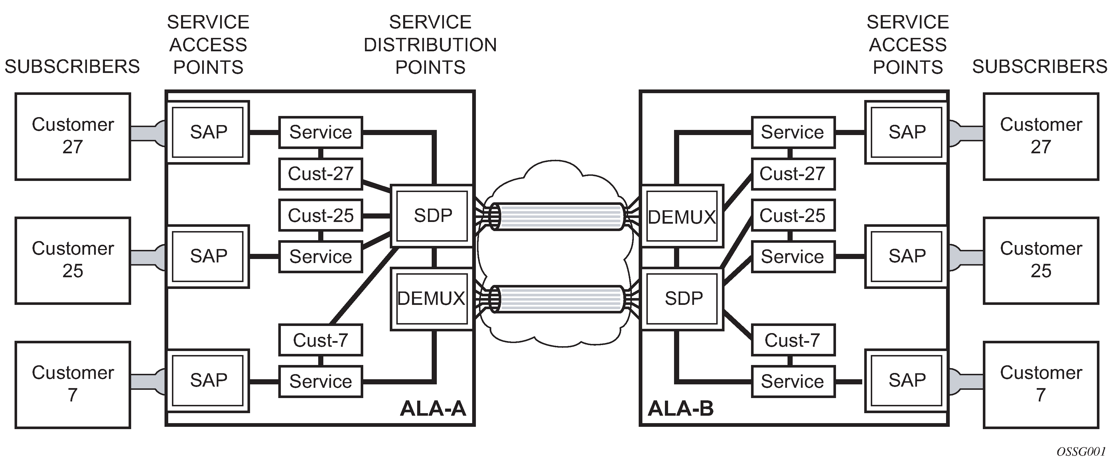
Service entities
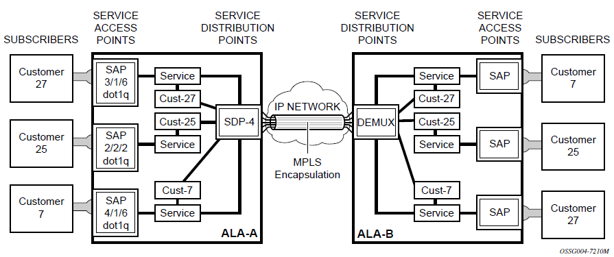
The following figure shows an example of the basic logical entities in the service model used to construct a service for a 7210 SAS device configured in network mode.
Customers
The terms ‟customer” and ‟subscriber” are used synonymously. The most basic required entity is the customer ID value, which is assigned when the customer account is created. To provision a service, a customer ID must be associated with the service at the time of service creation.
SAPs
Each subscriber service type is configured with at least one SAP. A SAP identifies the customer interface point for a service on a 7210 SAS router (SAPs for 7210 SAS configured in network mode). The SAP configuration requires that slot, MDA, and port information be specified. The slot, MDA, and port parameters must be configured before provisioning a service (see the Cards, MDAs, and Ports sections of the 7210 SAS-Mxp, R6, R12, S, Sx, T Interface Configuration Guide).
A SAP is a local entity to the router and is uniquely identified by:
physical Ethernet port
encapsulation type
encapsulation identifier (ID)
Depending on the encapsulation, a physical port can have more than one SAP associated with it. SAPs can only be created on ports designated as ‟access” in the physical port configuration.
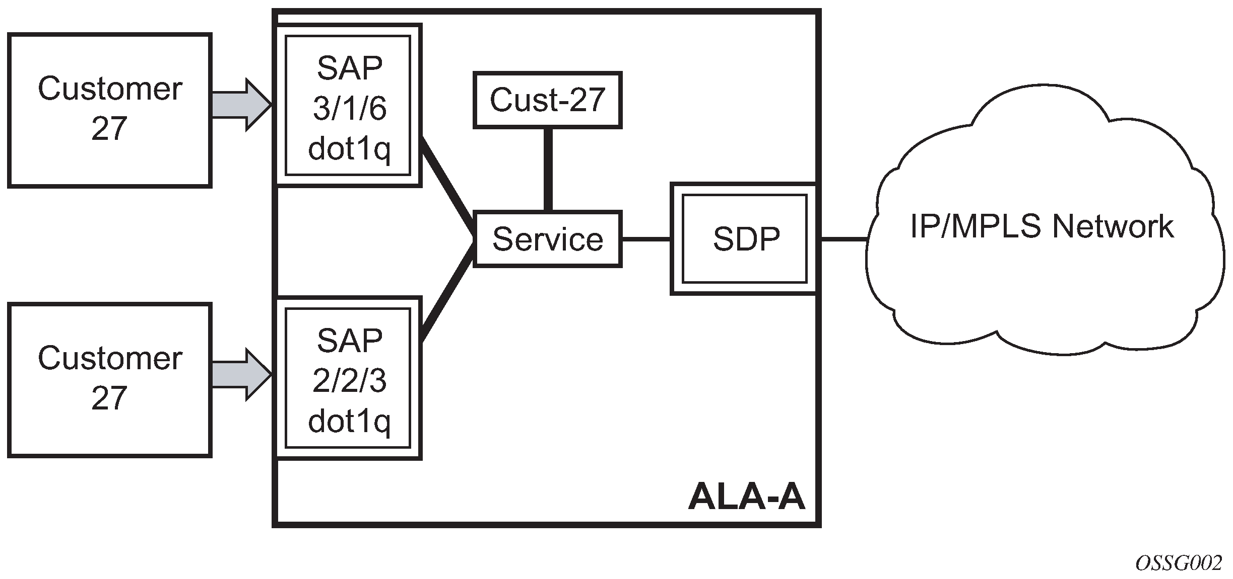
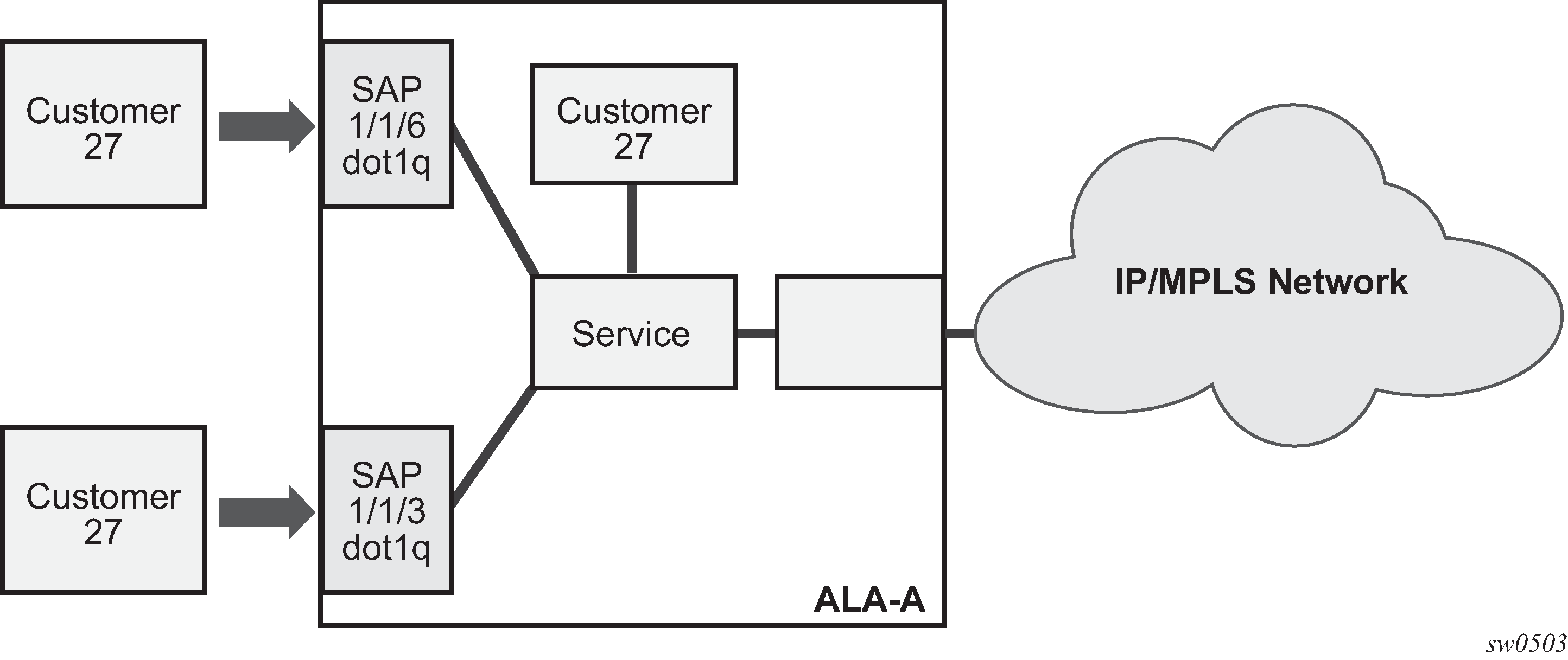
The following figure shows SAPs used for customer service delivery, with SDP used for service transport on 7210 SAS devices that support MPLS uplinks (also known as network mode platforms).
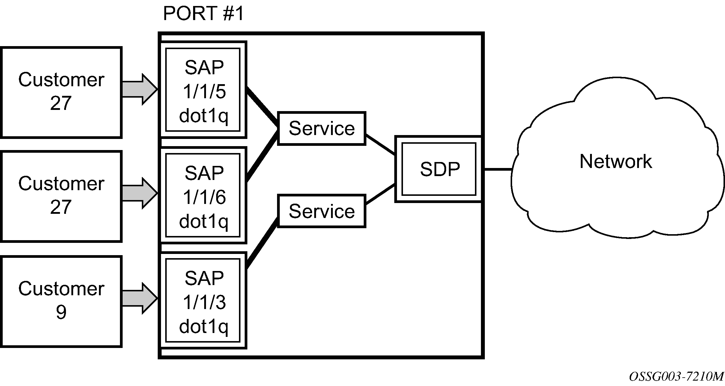
The following figure shows multiple SAPs used for customer service delivery, with access-uplink SAPs (also known as QinQ SAPs) used for service transport on 7210 SAS devices that support only Layer 2 uplinks (also known as access-uplink mode platforms).
SAP encapsulation types and identifiers
The encapsulation type is an access property of a service Ethernet port. The appropriate encapsulation type for the port depends on the requirements to support multiple services on a single port on the associated SAP and the capabilities of the downstream equipment connected to the port. For example, a port can be tagged with IEEE 802.1Q (referred to as dot1q) encapsulation in which each individual tag can be identified with a service. A SAP is created on a specific port by identifying the service with a specific encapsulation ID.
Ethernet encapsulations
The following are the encapsulation service options on Ethernet ports:
null
Supports a single service on the port. For example, where a single customer with a single service customer edge (CE) device is attached to the port. The encapsulation ID is always 0 (zero).
dot1q
Supports multiple services for one customer or services for multiple customers (Multiple SAPs on a single port (7210 SAS configured in network mode)). The encapsulation ID used to distinguish an individual service is the VLAN ID in the IEEE 802.1Q header. For example, the port is connected to a Ethernet switch with multiple downstream customers.
QinQ
The QinQ encapsulation type adds a IEEE 802.1Q tag to the 802.1Q tagged packets entering the network, to expand the VLAN space by tagging tagged packets, producing a double-tagged frame. The 7210 SAS supports QinQ encapsulation for access ports in network mode. In access-uplink mode, QinQ encapsulation is supported for both access ports and access-uplink ports.
The following are the encapsulation service options on Ethernet access-uplink ports:
QinQ
The QinQ encapsulation type adds a IEEE 802.1Q tag to the 802.1Q tagged packets entering the network, to expand the VLAN space by tagging tagged packets, producing a double-tagged frame.
The following figure shows multiple SAPs used for customer service delivery on the same port and belonging to the same service, along with SDP used for service transport on 7210 SAS devices that support MPLS uplinks (also known as network mode platforms). This is supported only in network mode.
Services and SAP encapsulations
The following table lists the service and SAP encapsulation information for Ethernet ports.
Port type |
Encapsulation |
|---|---|
Ethernet |
Null |
Ethernet |
Dot1q |
Ethernet |
QinQ |
Default SAP on a dot1q port
This feature provides default SAP functionality on dot1q-encapsulated ports. On a dot1q-encapsulated port where a default SAP is configured, all packets with q-tags not matching any explicitly defined SAPs will be assigned to this SAP. SAPs with default dot1q encapsulation are supported in VPLS and Epipe services. Dot1q default SAPs are not supported in VPRNs.
In this context, the character ‟*” indicates default, which means allow through. The default SAP also accepts untagged or priority-tagged packets. A default SAP must be configured explicitly. When a default SAP is not configured explicitly, packets not matching any explicitly defined SAPs will be dropped.
One of the applications where this feature can be applicable is an access connection of a customer who uses the whole port to access Layer 2 services. The internal VLAN tags are transparent to the service provider. This can be provided by a null-encapsulated port.
In this type of environment, logically two SAPs exist: a management SAP and a service SAP. The management SAP can be created by specifying a VLAN tag that is reserved to manage the CPE. The service SAP covers all other VLANs and behaves as a SAP on a null-encapsulated port.
There are a few constraints related to the use of a default SAP on a dot1q-encapsulated port:
This type of SAP is supported only on VPLS and Epipe services, and cannot be created in IES and VPRN services because it cannot preserve VLAN tag markings.
For VPLS SAPs with STP enabled, STP listens to untagged and null-tagged BPDUs only. All other tagged BPDUs are forwarded like other customer packets. This is the same behavior as null-encapsulated ports.
This type of SAP is mutually exclusive of a SAP defined by explicit null encapsulation (for example, 1/1/1:0). This avoids conflict as with which SAP untagged frames should be associated.
IGMP snooping is not supported on a default SAP. This would require remembering VLAN tags per hosts. By not allowing IGMP snooping on this SAP, all IGMP packets will be transparently forwarded.
Default SAPs on a QinQ port (supported only on 7210 SAS devices configured in access-uplink mode)
Default QinQ SAPs (notation *.*) are used in ring ports to avoid the need to configure services on all the intermediate nodes in the ring that are transiting the service. Default QinQ SAPs match all VLAN-tagged traffic that is not classified into any other SAP configured on the same port. Only one Epipe service with default QinQ SAPs is needed for transit service traffic on access-uplink ports.
Default QinQ SAPs are only allowed on access-uplink ports and access ports. A default QinQ SAP can coexist with a 0.* SAP on an access-uplink or access port. A default QinQ SAP accepts only tagged packets. Untagged packets or priority-tagged packets are not accepted on default QinQ SAPs.
When an Epipe service with default QinQ SAPs on the ring ports is used for transit traffic in a ring deployment, no protection mechanism (for example, STP or G.8032) is supported for default QinQ SAPs. The upstream or head-end node on which the service originates must ensure that the correct path on the ring is selected using either G.8032 or STP.
When a VPLS service with default QinQ SAPs on the ring ports is used for transit traffic in a ring deployment, users can use either G.8032 or M-VPLS with xSTP for ring protection. When using G.8032, the state of the default QinQ SAPs in the VPLS service can be managed using a separate G.8032 control instance.
A G.8032 control instance cannot use default QinQ SAPs.
A default QinQ SAP is available for use only in an Epipe and a VPLS service created with the svc-sap-type parameter set to null-star. A default QinQ SAP can be configured along with other SAPs allowed in the same service (that is, service with the svc-sap-type parameter set to null-star).
The following features are available for use with default QinQ SAPs configured in Epipe and VPLS service (unless explicitly specified, the following features are applicable for both Epipe and VPLS service).
The following features are available for default QinQ SAPs on either access ports or access-uplink ports:
MAC learning and aging is available for use in a VPLS service.
Per-SAP MAC limit is available for use in a VPLS service.
Mac-move detection and Mac-pinning is available for use in a VPLS service.
Discard-unknown and discard-unknown-source is available for use in a VPLS service.
Eth-CFM and Y.1731 is not available for use.
STP (and all its different flavors) cannot be enabled in the service with default QinQ SAPs.
MVPLS with xSTP can be used for loop prevention. The default QinQ SAPs inherit the state from the associated MVPLS instance.
A G.8032 control instance cannot be configured in a service with a default QinQ SAP.
G.8032 can be used for loop prevention in ring deployments, where the default QinQ SAPs are configured on the ring ports in a VPLS service. A separate G.8032 control instance must be configured for use on the ring ports, and the service with default QinQ ports needs to be associated with this G.8032 control instance.
IGMP snooping is not available for use.
L2PT and BPDU translation is not available for use.
IP interface in a VPLS service is not supported in a service using this SAP.
The following features are available for default QinQ SAPs created on access-uplink port:
Ingress QoS policy applied on an access-uplink port is available for classification and policing on ingress.
Egress QoS policy applied on an access-uplink port is available for egress queue shaping, scheduling, and marking.
SAP ingress ACLs are available for use.
SAP egress ACLs are not available for use.
SAP ingress received count and SAP egress forwarded count are available for use (appropriate accounting records can be used).
The following features are available for default QinQ SAPs created on access ports:
SAP ingress QoS policy is available for use.
Egress QoS policy applied on an access port is available for egress shaping, scheduling, and marking.
SAP ingress ACLs are available for use.
SAP egress ACLs are not available for use.
SAP ingress meter counters, SAP ingress received counters, and SAP egress forwarded counters are available for use (appropriate accounting records can be used).
Configuration notes for use of default QinQ SAPs for transit service in a ring deployment
The following considerations apply to default QinQ SAPs for transit service in a ring deployment configurations:
If an Epipe service is used with default QinQ SAPs on the ring ports for transit service in a ring deployment, no protection mechanism is available for the transit service (that is, Epipe service with the default QinQ SAPs on ring ports). Both Epipe and VPLS services that are originating on different nodes in the ring can use the transit service.
Protection and loop-detection mechanisms can be implemented for VPLS service configured in the ring nodes, by using MVPLS with xSTP on the nodes where the VPLS service is configured. No protection mechanisms are available for use with Epipe services on the node that originates the service.
If a VPLS service is used with default QinQ SAPs on the ring ports for transit service in a ring deployment, either MVPLS/xSTP or G.8032 can be used to protect the transit service (that is, VPLS service with the default QinQ SAPs on ring ports). In this case, VPLS services that are originating on different nodes in the ring and use the transit VPLS service are also protected. Epipe services that are originating on different nodes in the ring cannot use the transit VPLS service.
When using VPLS service with default QinQ SAPs for transit service with either G.8032 or MVPLS with xSTP configured for protection, load-balancing of the traffic based on the VLAN IDs is not possible. If load-balancing is needed, it is better to use Epipe service with default QinQ SAPs as the transit service.
SAP configuration considerations for network mode and access-uplink mode
The following considerations apply to network mode and access-uplink mode SAP configurations:
A SAP is a local entity and only locally unique to a specific device. The same SAP ID value can be used on another 7210 SAS-series router.
By default, no SAPs are configured on the node. All SAPs in subscriber services must be created.
At creation, the default administrative state for a SAP is set to administratively enabled.
When a SAP is deleted, all configuration parameters for the SAP are also deleted.
A SAP is owned by and associated with the service in which it is created in each router.
On a port with a dot1q encapsulation type, traffic for the SAP is identified based on a specific IEEE 802.1Q VLAN ID value. The VLAN ID is stripped off at SAP ingress and the appropriate VLAN ID added at SAP egress. As a result, VLAN IDs only have local significance, and configuring identical VLAN IDs for each SAP on a service is not required.
If a port is administratively shut down, all SAPs on that port are operationally out of service.
QinQ access SAPs of type Q1.0 are supported only for IES, VPRN, and R-VPLS services. They are not supported for Layer 2 services.
A SAP cannot be deleted until it has been administratively disabled (shutdown).
Each SAP can have one each of the following policies assigned:
Ingress filter policy
Egress filter policy
Ingress QoS policy
Accounting policy
SAP configuration notes when operating 7210 SAS devices in network mode only
When provisioned in network mode, the following SAP configuration guidelines are applicable.
The following table describes SAP and service (svc-sap-type) combinations for Layer 2 services (when in network mode).
svc-sap-type (Layer 2 service) |
Access SAPs |
SDP bindings |
|---|---|---|
Any (without any QinQ SAP in the same service) |
Null SAP, dot1q SAP, dot1q default SAP, dot1q explicit null SAP, Q1.* SAP, 0.* SAP (accepts only untagged frames) |
PW with vc-type set to vc-ether or vc-vlan |
Any (with QinQ SAP in the same service) |
Null SAP (accepts only untagged frames), Dot1q SAP (accepts only a single tag frame, Dot1q explicit null SAP (accepts only untagged frame), Q1.Q2 SAP (accepts frames with only two tags), 0.* SAP (accepts only untagged frames) |
PW with vc-type set to vc-ether or vc-vlan (accepts only untagged frames on vc-ether PW and only tagged frames on vc-vlan PW) |
Any (with dot1q-range SAP) |
Dot1q range SAP, Q1.* SAP |
PW with vc-type set to vc-ether or vc-vlan (no checks on VLAN ID for packets received on PW) |
Qinq-inner-tag-preserve |
Q1.Q2 SAP (inner tag Q1 is not stripped), dot1q SAP (no tags are stripped) |
PW with vc-vlan (vc-vlan is not stripped) |
QinQ SAP Configuration Restrictions for 7210 SAS platforms in network operating mode
The following are the QinQ access SAP configuration guidelines for 7210 SAS in network mode only.
These guidelines are not applicable when 7210 SAS devices are operating in access-uplink mode and access-uplink SAPs are in use:
Tagged packets received on SAPs configured in a service in which a QinQ SAP is also in use are processed (not applicable when a QinQ SAP is not provisioned in a service).
When a QinQ SAP is configured in a service, the number of VLAN tags in the packets received on null SAP, dot1q SAP, and QinQ SAP configured in the same service should match the number of VLAN tags implied by the port encapsulation mode. Packets that do not match are dropped by the hardware. That is, packets received with more than two VLAN tags on a QinQ SAP are dropped, packets received with more than one VLAN tag on a Dot1q SAP are dropped, and packets received with tags (even packets with a priority tag) on a null SAP are dropped. In this document, such packets are referred to as extra-tag packets.
When a QinQ SAP is configured in a service, the number of VLAN tags in the packets received on the VC/pseudowire of type vc-vlan should be exactly one and packets received on the VC/pseudowire of type vc-ether should contain no tags (not even priority tags). If either case, packets that contain more VLAN tags than the number specified previously are dropped. In this document, such packets are referred to as extra-tag packets.
The system will provide a limited number of counters for the extra-tag packets dropped on SAP ingress. These counters are intended for diagnostic use.
The following table shows the SAP types allowed in a service when QinQ SAP is in use.
Table 3. SAP types in a service when QinQ SAP is in use (network mode operation) SAP configured in the service
SAPs not allowed for configuration in the same service
QinQ
Q.* SAP, dot1q default SAP
Q.*
Q1.Q2
Dotq1 default SAP
Q1.Q2
A 0.* QinQ SAP configured in the service will only accept untagged or priority-tagged packets, regardless of whether a QinQ SAP is configured in the service.
The 7210 SAS platforms support a mechanism to transport QinQ packets in an Epipe with two or more tags, with some restrictions. For more information, see Epipe services.
SAP configuration notes for 7210 SAS platforms in access-uplink operating mode
When provisioned in access-uplink mode, the following SAP configuration guidelines are applicable.
The following table describes SAP and service combinations allowed in access-uplink mode.
svc-sap-type |
Access SAPs |
Access uplink SAPs |
|---|---|---|
null-star |
Null SAP, dot1q default SAP, default QinQ SAP (*.* SAP) |
Q.* SAP, default QinQ SAP (*.* SAP) |
dot1q-preserve |
Dot1q SAP (dot1q VLAN tag is not stripped on ingress), Q1.Q2 SAP (Q2 tag VLAN ID must match the dot1q SAP VLAN ID) |
Q1.Q2 SAP (Q2 tag VLAN ID must match the dot1q SAP VLAN ID) |
any |
Null SAP, dot1q SAP, dot1q explicit null SAP, Q1.Q2 SAP, Q.* SAP, 0.* SAP |
Q1.Q2 SAP, Q.* SAP, 0.* SAP |
dot1q-range |
Dot1q SAP (dot1q VLAN tag not stripped on ingress), Q1.* SAP |
Q1.* SAP |
The following guidelines apply to SAPs:
The svc-sap-type parameter value determines the type of SAPs that are allowed to be provisioned in a service.
A physical port can only have one SAP to be part of one service. Multiple SAPS can be defined over a physical port but each of these SAPs must belong to a different service.
If a service sap-type is specified as dot1q-preserve, all the SAPs configured in the service must have the same VLAN ID. The outermost VLAN tag of the packets received on the access port is not stripped, when svc-sap-type is set to dot1q-preserve.
A dot1q default SAP cannot be configured when svc-sap-type is set to any.
When svc-sap-type is set to any for a null SAP, the system processes and forwards only packets with no VLAN tag (that is, untagged). All other packets with one or more VLAN tags (even those with priority tag only) are not processed and are dropped. Users can use the service with svc-sap-type set to null-star, to process and forward packets with one or more tags (including priority tag) on a null SAP.
An ingress QoS policy and accounting policy is assigned per access-uplink port and cannot be assigned per access-uplink SAP.
The default QinQ SAP processes only tagged packets received on a QinQ port. All tagged packets that do not match the specific SAP tags configured on the same port are processed by this SAP. The default QinQ SAP cannot process un-tagged packets, even if 0.* SAP is not configured for use on that port.
The default QinQ SAP is available for use with 0.* SAPs configured on the same port or in the same service. It is available for use with another default QinQ SAP configured in the same service (on a different port). In a VPLS service, the default QinQ SAP is available for use with any other SAP type configured in a service configured with svc-sap-type parameter set to null-star.
SAPs using connection-profile (to specify dot1q VLAN ranges or individual VLAN IDs) can be configured in a service only when svc-sap-type is set to dot1q-range.
When a service is configured to use svc-sap-type dot1q-range, the outermost V-LAN tag of the packets is not stripped when the packet is received on access port ingress. See Epipe services for more information about the processing behavior for this type of service.
SDPs
SDPs are supported by all 7210 SAS platforms as described in this document, except those operating in access-uplink mode.
An SDP provides a logical way to direct traffic from one router to another through a unidirectional (one-way) service tunnel. The SDP terminates at the far-end device which directs packets to the correct service egress SAPs on that device. A distributed service consists of a configuration with at least one SAP on a local node, one SAP on a remote node, and an SDP that binds the service to the service tunnel.
An SDP has the following characteristics:
An SDP is locally unique to a participating router. The same SDP ID can appear on other 7210 SAS-series routers.
An SDP uses the system IP address to identify the far-end edge router.
An SDP is not specific to any one service or any type of service. When an SDP is created, services are bound to the SDP. An SDP can also have more than one service type associated with it.
All services mapped to an SDP use the same transport encapsulation type defined for the SDP.
An SDP is a management entity. Even though the SDP configuration and the services carried within are independent, they are related objects. Operations on the SDP affect all the services associated with the SDP. For example, the operational and administrative state of an SDP controls the state of services bound to the SDP.
An SDP from the local device to a far-end router requires a return path SDP from the far-end 7210 SAS-series back to the local router. Each device must have an SDP defined for every remote router to which it needs to provide service. SDPs must be created first, before a distributed service can be configured.
SDP binding
The following figure shows an example SDP binding. To configure a distributed service from ALA-A to ALA-B, the SDP ID must be specified in the service creation process to bind the service to the tunnel (the SDP). Otherwise, service traffic is not directed to a far-end point and the far-end devices cannot participate in the service (there is no service). To configure a distributed service from ALA-B to ALA-A, the SDP ID must be specified.
Spoke and mesh SDPs
SDPs are supported by all 7210 SAS platforms as described in this document, except those operating in access-uplink mode.
When an SDP is bound to a service, it is bound as either a spoke-SDP or a mesh SDP. The type of SDP indicates how flooded traffic is transmitted. The 7210 SAS network mode devices support both spoke and mesh SDPs.
A spoke-SDP is treated like the equivalent of a traditional bridge port where flooded traffic received on the spoke-SDP is replicated on all other ports and not transmitted on the port it was received.
All mesh SDPs bound to a service are logically treated like a single bridge port for flooded traffic where flooded traffic received on any mesh SDP on the service is replicated to other ports (spoke-SDPs and SAPs) and not transmitted on any mesh SDPs.
SDP using BGP route tunnel
SDPs are enhanced to use BGP route tunnels to extend inter-AS support for Layer 2 and Layer 3 VPN services. An SDP can be configured to use the MPLS transport method. MPLS SDP support is enhanced to allow a BGP route tunnel to reach the far-end PE. A single method of tunneling is allowed per SDP (for example, LDP, RSVP-TE LSP, or BGP route tunnel). The BGP route tunnel method is excluded if multimode transport is enabled for an SDP.
For inter-AS far-end PE, the next hop for the BGP route tunnel must be one of the local ASBRs. The LSP type selected to reach the local ASBR (BGP labeled route next-hop) must be configured under the BGP global context. LDP must be supported to provide a transport LSP to reach the BGP route tunnel next-hop.
Only BGP route labels can be used to transition from an ASBR to the next-hop ASBR. The global BGP route tunnel transport configuration option must be entered to select an LSP to reach the PE node from the ASBR node. On the last BGP segment, both BGP+LDP and LDP routes may be available to reach the far-end PE from the ASBR node. An LDP LSP must be preferred because of higher protocol priority. This leads to just one label, besides other labels in the stack to identify the VC/VPN at far-end PE nodes.
SDP keepalives
SDP keepalives actively monitor the SDP operational state using periodic SDP ping echo request and echo reply messages. SDP ping is a part of the suite of service diagnostics built on a Nokia service-level OA&M protocol. When SDP ping is used in the SDP keepalive application, the SDP echo request and echo reply messages are a mechanism for exchanging far-end SDP status.
Configuring SDP keepalives on a specific SDP is optional. SDP keepalives for a particular SDP have the following configurable parameters:
admin up/admin down state
hello time
message length
max drop count
hold down time
SDP keepalive echo request messages are only sent when the SDP is completely configured and administratively up and SDP keepalives are administratively up. If the SDP is administratively down, keepalives for the SDP are disabled.
SDP keepalive echo request messages are sent out periodically, based on the configured hello time. An optional message length for the echo request can be configured. If max drop count echo request messages do not receive an echo reply, the SDP will immediately be brought operationally down.
If a keepalive response is received that indicates an error condition, the SDP will immediately be brought operationally down.
When a response is received that indicates the error has cleared and the hold down time interval has expired, the SDP will be eligible to be put into the operationally up state. If no other condition prevents the operational change, the SDP will enter the operationally up state.
See Configuring an SDP for information about configuring keepalive parameters.
Mixed-LSP mode of operation
The mixed-LSP mode of operation allows for a maximum of two LSP types to be configured within an SDP: primary LSP type and a backup LSP type. An RSVP primary LSP type can be backed up by an LDP LSP type.
An LDP LSP can be configured as a primary LSP type, which can then be backed up by a BGP LSP type.
At any time, the service manager programs only one type of LSP in the line card, which will activate it to forward service packets according to the following priority order:
RSVP LSP type
One RSVP LSP can be configured per SDP. This is the highest priority LSP type.
LDP LSP type
One LDP FEC will be used per SDP. The 7210 SAS does not support LDP ECMP.
BGP LSP type
One RFC 3107-labeled BGP prefix programmed by the service manager.
In the case of the RSVP/LDP SDP, the service manager will program the NHLFEs for the active LSP type, preferring the RSVP LSP type over the LDP LSP type. If no RSVP LSP is configured or all configured RSVP LSPs go down, the service manager will reprogram the line card with the LDP LSP, if available. If not, the SDP goes operationally down.
When a higher priority LSP type becomes available, the service manager reverts to this LSP at the expiry of the revert-time timer or the failure of the currently active LSP, whichever comes first. The service manager then reprograms the line card accordingly. If the infinite value is configured, the SDP reverts to the highest priority LSP type only if the currently active LSP failed.
LDP uses a tunnel down damp timer that is set to three seconds by default. If the LDP LSP fails, the SDP reverts to the RSVP LSP type after the timer expires. For an immediate switchover, the timer should be set to zero using the configure>router>ldp>tunnel-down-damp-time command. See the 7210 SAS-Mxp, R6, R12, S, Sx, T MPLS Guide for more information.
If the value of the revert-time timer is changed, it comes into effect only at the next use of the timer. Any timer that is outstanding at the time of the change is restarted with the new value.
In the case of the LDP/BGP SDP, the service manager prefers the LDP LSP type over the BGP LSP type. The service manager reprograms the line card with the BGP LSP, if available; otherwise, the SDP is placed in the operationally down state.
An LDP/BGP SDP has differences in behavior compared to an RSVP/LDP SDP. For a specific /32 prefix, only a single route will exist in the routing table: the IGP route or the BGP route. Therefore, either the LDP FEC or the BGP label route is active at any time. As a result, the tunnel table needs to be reprogrammed each time a route is deactivated and another is activated. Also, the SDP revert-time cannot be used, because there is no situation where both LSP types are active for the same /32 prefix.
SAP and service scaling with high SAP scale mode
This feature is supported only on the 7210 SAS-Mxp, 7210 SAS-Sx/S 1/10GE (standalone), and 7210 SAS-Sx 10/100GE (standalone).
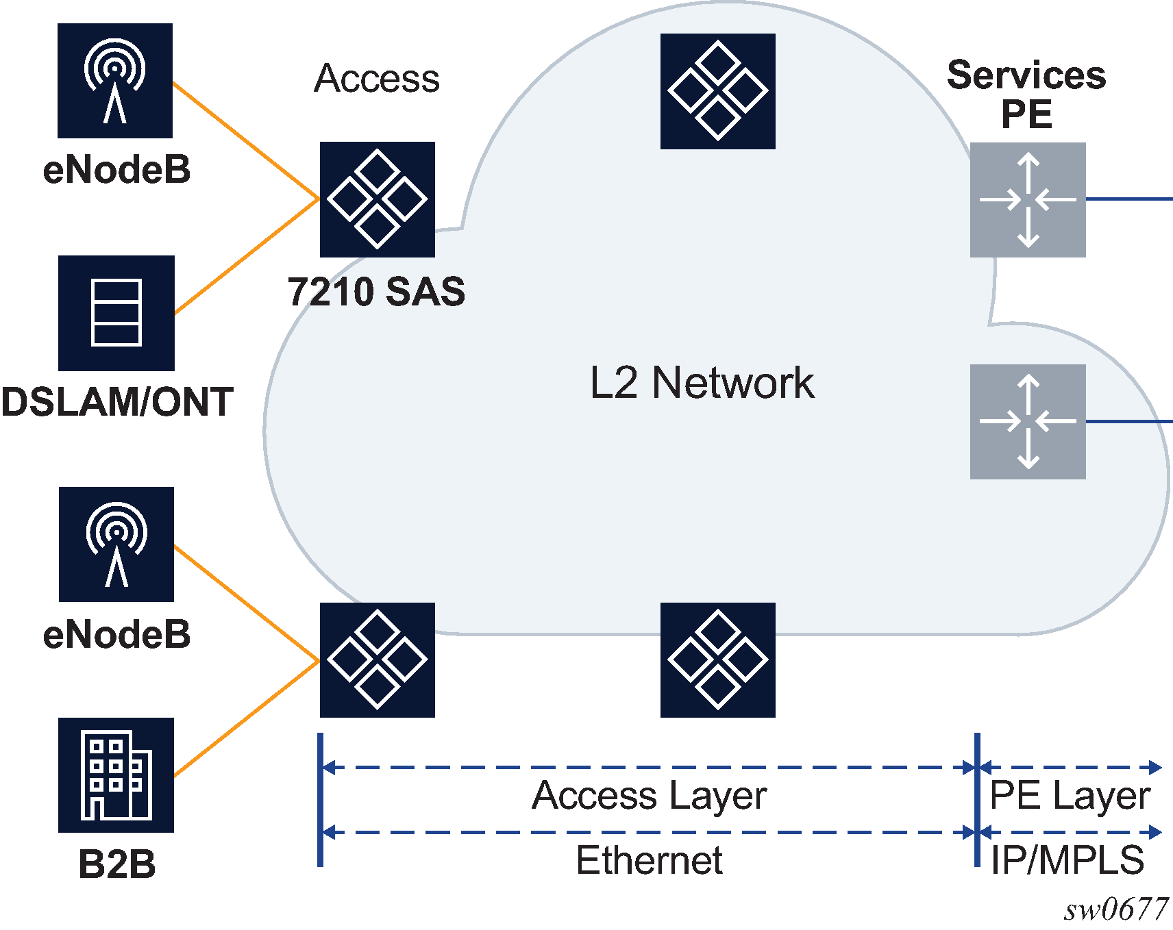
In Layer 2 access networks used to backhaul service traffic from business services, mobile backhaul, and residential services, the 7210 SAS-Mxp, 7210 SAS-Sx/S 1/10GE, and 7210 SAS-Sx 10/100GE platforms act as Layer 2 carrier Ethernet switching platforms with VLAN-based Layer 2 uplinks. To perform this role, these platforms must support higher SAP and service scaling. To do so, these platforms use the SAP scale mode and port-based access ingress policies.
On the 7210 SAS-Mxp, 7210 SAS-Sx/S 1/10GE, and 7210 SAS-Sx 10/100GE, sap-scale-mode can be configured in standalone mode and does not require a BOF configuration.
The following figure shows the use of Layer 2 uplinks in a Layer 2 access network with a 7210 SAS-Mxp, 7210 SAS-Sx/S 1/10GE, or 7210 SAS-Sx 10/100GE.
The SAP scale mode is configured using the configure>system>resource-profile>sap-scale-mode {high | low} command. By default, the low option is configured for low SAP scale mode, which provides backward compatibility. The user can configure the high option to use high SAP scale mode, which allows the configuration of a higher number of services and SAPs. Before changing the sap-scale-mode value, the user must perform the following:
Remove all service and SAP configurations.
Change the value of sap-scale-mode and enable per-port egress queuing using the configure>system>resource-profile>qos>port-scheduler-mode command.
Reboot the node.
Reconfigure all SAPs and services as required.
In high SAP scale mode, the system supports higher SAP and service scaling for Epipe/VLL and VPLS services only. SAP and service scaling for IES, VPRN, and RVPLS services remain unchanged.
QoS policies support port-based access ingress policies on access ports to facilitate the use of access ports as Layer 2 uplinks. With the use of ports as Layer 2 uplinks, the user can apply a single port-based access ingress policy at ingress of an access port, instead of using per-SAP ingress policies. This allows a single policy definition to be used to classify and rate-limit all traffic received over access ports used as Layer 2 uplinks (similar to a network port-based policy applied to network ports used as uplinks) instead of using per SAP ingress policies. Resources must be allocated using the configure>system>resource-profile command to use access ingress QoS policies on an access port.
In addition, only the following QoS policies can be used in the high SAP scale mode to achieve a higher scale:
access port-based egress queuing and shaping on all ports, including service delivery ports and uplinks
access port-based ingress classification and policing on uplinks
Epipe and VPLS SAPs using ingress table-based classification and policing on service delivery ports for higher SAP scale
IES and VPRN SAPs using table-based classification or CAM-based classification
RVPLS SAPs using CAM-based classification and policing
default SAP ingress QoS policy of 65536 for the 7210 SAS-Mxp and 1 for the 7210 SAS-Sx/S 1/10GE and 7210 SAS-Sx 10/100GE.
The following SAP configuration restrictions apply to the high SAP scale mode; see SAPs for additional SAP configuration guidelines:
If an RVPLS Q1.* SAP is configured, SAPs (Q1.Q2 SAP) with a matching Q1 tag cannot be configured in other VPLS, Epipe, IES, and VPRN services on the same port.
If a VPLS Q1.* SAP enabled with DHCP snooping is configured, SAPs (Q1.Q2 SAP) with a matching Q1 tag cannot be configured in other VPLS, Epipe, IES, and VPRN services on the same port. They can use other values for the Q1 tag. The reverse is also true.
The dot1p default SAP cannot be configured in RVPLS services; it is only supported in Epipe, VPLS, IES, and VPRN services.
If the following criteria are met on the 7210 SAS-Sx 10/100GE, IES and VPRN SAPs for IES or VPRN services are not supported:
the SAP has a QinQ encapsulation
access-ingress-qos-mode is set to port-mode
sap-scale-mode is set to high
Guidelines for configuring high SAP scale mode
Perform the following procedure to change the sap-scale-mode low to the sap-scale-mode high configuration:
Delete all SAPs.
Configure the config>system>resource-profile>qos>port-scheduler-mode command.
Configure the sap-scale-mode command to use the high option.
Save the configuration and reboot the node.
Guidelines for configuring low SAP scale mode
Perform the following procedure to change the sap-scale-mode high to the sap-scale-mode low configuration:
Delete all SAPs.
If the access ingress QoS policy has attachments, reset the policy.
If the access-ingress-qos-mode command is set to port-mode, configure the command to use the sap-mode option.
Configure the sap-scale-mode command to use the low option.
Save the configuration and reboot the node.
G.8032 Ethernet ring protection switching
Ethernet ring (Eth-ring) protection switching provides ITU-T G.8032 specification compliance to achieve resiliency for Ethernet Layer 2 networks. Similar to G.8031 linear protection (also called Automatic Protection Switching (APS)), G.8032 Eth-ring is implemented on Ethernet OAM and often referred to as Ring Automatic Protection Switching (R-APS).
Eth-rings are supported on VPLS SAPs. VPLS services supporting Eth-ring SAPs can connect to other rings and Ethernet service using VPLS and R-VPLS SAPs. The Eth-ring service enables rings for core network or access network resiliency. A single point of interconnection to other services is supported. The Eth-ring service is a VLAN service providing protection for ring topologies and the ability to interact with other protection mechanisms for overall service protection. This ensures failures detected by Eth-ring only result in R-APS switchover when the lower layer cannot recover, and that higher layers are isolated from the failure.
Rings are preferred in data networks where the native connectivity is laid out in a ring or there is a requirement for simple resilient LAN services. Because of the symmetry and the simple topology, rings are viewed a good solution for access and core networks where resilient LANS are required. The Nokia implementation of G.8032 Eth-rings can be used for interconnecting access rings and to provide traffic engineered backbone rings. The 7210 SAS implementation of G.8032 Eth-rings supports dual interconnected rings with sub-rings.
Eth-rings use one VID per control per ring instance and use one (typically) or multiple VIDs for data instances per control instance. A dedicated control VLAN (ERP VLAN) is used to run the protocol on the control VID. G.8032 controls the active state for the data VLANs (ring data instances) associated with a control instance. Multiple control instances allow logically separate rings on the same topology. The Nokia implementation supports dot1q and QinQ encapsulation for data ring instances. The control channel supports dot1q and QinQ encapsulation.
Overview of G.8032 operation
R-APS messages that carry the G.8032 protocol are sent on a dedicated protocol VLAN called ERP VLAN (or ring control instance). In a revertive case, the G.8032 protocol ensures that one Ring Protection Link (RPL) owner blocks the RPL link. R-APS messages are periodically sent around in both directions to inform other nodes in the ring about the blocked port in the RPL owner node. In non-revertive mode, any link may be the RPL link.
Y.1731 Ethernet OAM CC is the basis of the R-APS messages. Y.1731 CC messages are typically used by nodes in the ring to monitor the health of each link in the ring in both directions. However, CC messages are not mandatory. Other link layer mechanisms could be considered; for example, loss of signal (LoS) when the nodes are directly connected.
Initially, each ring node blocks one of its links and notifies other nodes in the ring about the blocked link. When a ring node in the ring learns that another link is blocked, the node unblocks its blocked link, possibly causing an FDB flush in all links of the ring for the affected service VLANs, controlled by the ring control instance. This procedure results in unblocking all links except the one link and the ring normal (or idle) state is reached.
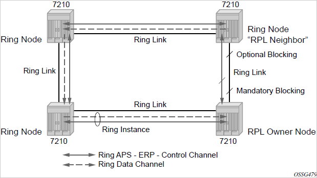
In revertive mode, the RPL link will be the link that is blocked when all links are operable after the revert time. In non-revertive mode, the RPL link is no different from other ring links. Revertive mode provides predictability, particularly when there are multiple ring instances, and the operator can control which links are blocked on the different instances. Each time that there is a topology change that affects reachability, the nodes may flush the FDB and MAC learning takes place for the affected service VLANs, allowing forwarding of packets to continue. The following figure shows this initial operational state.
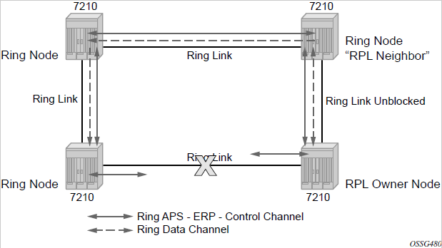
When a ring failure occurs, a node detecting the failure (enabled by Y.1731 OAM CC monitoring) sends an R-APS message in both directions. This allows the nodes at both ends of the failed link to block forwarding to the failed link, preventing it from becoming active. In revertive mode, the RPL owner then unblocks the previously blocked RPL and triggers an FDB flush for all nodes for the affected service instances. The ring is now in protecting state and full ring connectivity is restored. MAC learning takes place to allow Layer 2 packet forwarding on a ring. The following figure shows the failed link scenario.
When the failed link recovers, the nodes that blocked the link again send the R-APS messages indicating no failure this time. This causes the RPL owner to block the RPL link and indicate the blocked RPL link to the ring in an R-APS message. When the message is received by the nodes at the recovered link, they unblock that link and restore connectivity (again all nodes in the ring perform an FDB flush and MAC learning takes place). The ring is back in the normal (or idle) state.
Within each path, Y.1731 Maintenance Entity Group (MEG) Endpoints (MEPs) are used to exchange R-APS specific information (specifically to coordinate switchovers). As well, MEPs optionally exchange fast Continuity Check Messages (CCMs) providing an inherent failure detection mechanism as part of the protocol. Failure detection of a ring path by one of the mechanisms activates the protection links. Upon failure, reconvergence times are dependent on the failure detection mechanisms.
In the case of Y.1731, the CCM transmit interval determines the response time. The 7210 SAS device supports 100 ms message timers that allow for quicker restoration times. Alternatively, 802.3ah (Ethernet in the First Mile) or LoS can trigger a protection switch where appropriate. In the case of direct connectivity between the nodes, there is no need to use Ethernet CC messaging for liveliness detection.
Revertive and non-revertive behaviors are supported. The RPL is configured and Eth-rings can be configured to revert to the RPL upon recovery.
G.8032 supports multiple data channels (VIDs) or instances per ring control instance (R-APS tag). G.8032 also supports multiple control instances such that each instance can support RPLs on different links, providing for a load balancing capability. However, after services have been assigned to one instance, the rest of the services that need to be interconnected with those services must be on the same instance. That is, each data instance is a separate data VLAN on the same physical topology. When there is any one link failure or any one node failure in the ring, G.8032 protocols are capable of restoring traffic between all remaining nodes in these data instances.
R-APS can be configured on any port configured for access mode using dot1q or QinQ encapsulation, enabling support for R-APS protected services on the service edge toward the customer site, or within the Ethernet backbone. ELINE and ELAN services can be provided R-APS protection and, although the Eth-ring providing the protection uses a ring for protection, the services are configured independent of the ring properties. The intent of this is to cause minimum disruption to the service during R-APS failure detection and recovery.
In the 7210 SAS implementation, the Ethernet ring is built from a VPLS service on each node with VPLS SAPs that provides ring path with SAPs. As a result, most of the VPLS SAP features are available on Ethernet rings, if needed. This results in a fairly feature-rich ring service.
The control tag defined under each Eth-ring is used for encapsulating and forwarding the CCMs and the G.8032 messages used for the protection function. If a failure of a link or node affects an active Ethernet ring segment, the services will fail to receive the CC messages exchanged on that segment or will receive a fault indication from the Link Layer OAM module.
For failure detection using CCMs, three CC messages plus a configurable hold-off timer must be missed for a fault to be declared on the associated path. The latter mechanism is required to accommodate the existence of an additional 50 ms resiliency mechanism in the optical layer. After it receives the fault indication, the protection module will declare the associated ring link down and the G.8032 state machine will send the appropriate messages to open the RPL and flush the learned addresses.
Flushing is triggered by the G.8032 state machine and the 7210 SAS implementation allows flooding of traffic during the flushing interval to expedite traffic recovery.
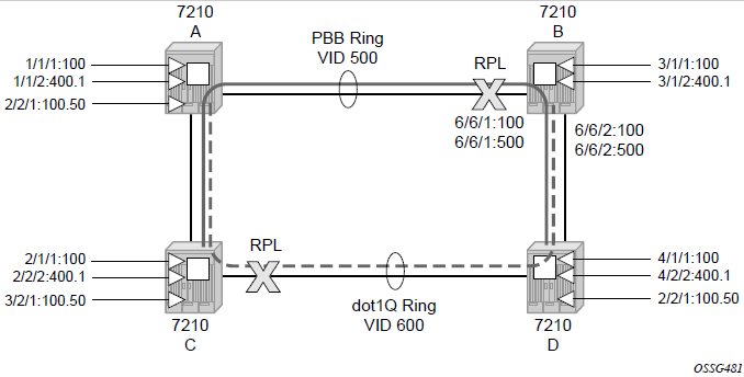
The following figure shows a resilient ring service example, in which a PBB ring (solid line) using VID 500 carries two service VLANs on I-SID 1000 and 1001 for service VIDs (dot1q 100 and QinQ 400.1, respectively). The RPL for the PBB ring is between A and B, where B is the RPL owner. The following figure also shows a QinQ service on the (dotted line) ring that uses Dot1q VID 600 for the ring to connect service VLAN 100.50.
The two rings have RPLs on different nodes, which allows a form of load balancing. The example demonstrates that service and ring encapsulation can be mixed in various combinations. Also, note that neither of the rings is a closed loop. A ring can restore connectivity when any one node or link fails to all remaining nodes within the 50ms transfer time (signaling time after detection).
Ethernet ring configuration
The following is a sample configuration that shows an Ethernet ring configuration.
configure eth-ring 1
     description "Ring PBB BLUE on Node B"
     revert-time 100
     guard-time 5
     ccm-hold-time down 100 up 200
     rpl-node owner
     path a 1/1/1 raps-tag 100 // CC Tag 100
          description "To A ring link"
          rpl-end
          eth-cfm
               mep 1 domain 1 association 1 direction down  // Control MEP
                    no shutdown
               exit
          exit
          no shutdown  // would allow protect switching
                       // in absence of the "force" command
     exit
     path b 6/6/2 raps-tag 100 //Tag 100
          description "to D Ring Link"
          eth-cfm
               mep 1 domain 1 association 1 direction down
                    no shutdown
               exit
          exit
          no shutdown
     exit
no shutdown
exit

service
     vpls 10 customer 1 create // Ring APS SAPs
          description "Ring Control VID 100"
          sap 1/1/1:100 eth-ring 1 create  // TAG for the Control Path a
          exit
          sap 6/6/2:100 eth-ring 1 create  // TAG for the Control Path b
          exit
          no shutdown
     exit
service
     vpls 40 customer 1 b-vpls create //Data Channel on Ring
          description "Ethernet Ring 1 VID 500"
          sap 1/1/1:500 eth-ring 1 create   // TAG for the Data Channel Path a
          exit
          sap 6/6/2:500 eth-ring 1 create   // TAG for the Data Channel Path b
          exit
     exit

service
     epipe 100 pbb-epipe   // CPE traffic
          description "PBB epipe service for CPE"
                 pbb-tunnel 40 backbone-dest-mac 00:bb:bb:bb:bb:bb isid 100
                 sap 3/1/1:100 create
                     description "Default sap description for service id 100"
                 exit
                 no shutdown
     exit
Ethernet ring sub-rings
Ethernet sub-rings offer a dual redundant way to interconnect rings. The 7210 SAS supports sub-rings connected to major rings, and a sub-ring connected to a VPLS (LDP based) for access ring support in VPLS networks.
The following figure shows a major ring and sub-ring scenario. In this scenario, any link can fail in either ring (ERP1 or ERP2) and each ring is protected. Also, the sub-ring (ERP2) relies on the major ring (ERP1) as part of its protection for the traffic from C and D. The nodes C and D are configured as interconnection nodes.
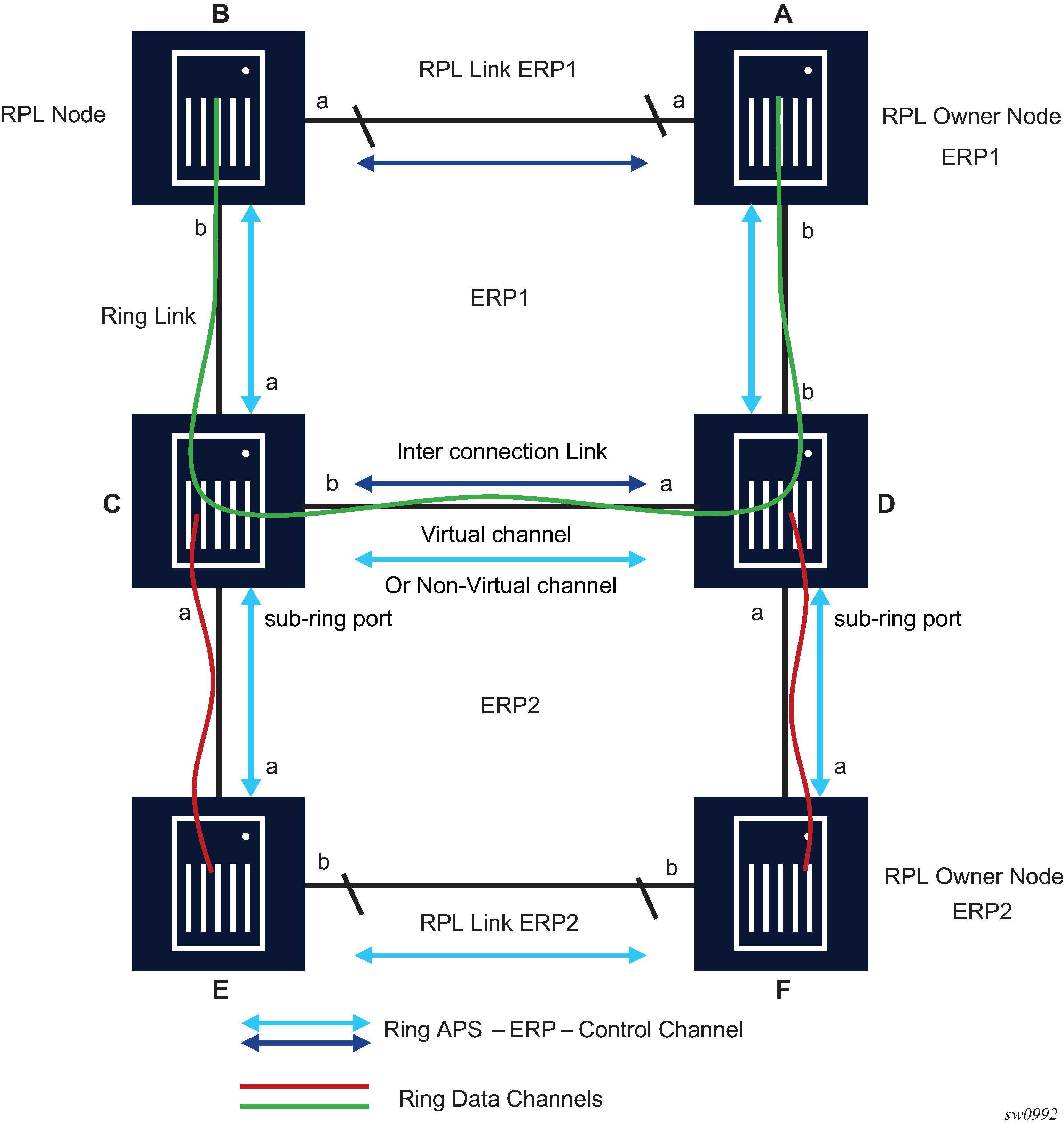
Sub-rings and major rings run similar state machines for the ring logic; however, there are some differences. When sub-rings protect a link, the flush messages are propagated to the major ring. (A special configuration allows control of this option on the 7210 SAS.) When major rings change topology, the flush is propagated around the major ring and does not continue to any sub-rings. The reason for this is that major rings are completely connected but sub-rings are dependent on another ring or network for full connectivity. The topology changes need to be propagated to the other ring or network usually. Sub-rings offer the same capabilities as major rings in terms of control and data so that all link resources may be used.
Virtual and non-virtual channel
The following is a sample sub-ring using virtual-link configuration output on Node C, interconnecting node.
eth-ring 2
        description "Ethernet Sub Ring on Ring 1"
            interconnect ring-id 1 // Link to Major Ring 1
                propagate-topology-change
            exit
        exit
        path a 1/1/3 raps-tag 100 // Ring control uses VID 100
            eth-cfm
                mep 9 domain 1 association 4
                    ccm-enable
                    control-mep
                    no shutdown
                exit
            exit
            no shutdown
        exit
        no shutdown
    exit
sub-ring non-virtual-link // Not using a virtual link

# Control Channel for the Major Ring ERP1 illustrates that Major ring
# control is still separate from Sub-ring control
  vpls 10 customer 1 create
      description "Control VID 10 for Ring 1 Major Ring"
      stp shutdown
      sap 1/1/1:10 eth-ring 1 create
          stp shutdown
          exit
      sap 1/1/4:10 eth-ring 1 create
          stp shutdown
          exit
      no shutdown
  exit

# Data configuration for the Sub-Ring

  vpls 11 customer 1 create
      description "Data on VID 11 for Ring 1"
      stp shutdown
      sap 1/1/1:11 eth-ring 1 create // VID 11 used for ring
          stp shutdown
      exit
      sap 1/1/4:11 eth-ring 1 create
          stp shutdown
      exit
      sap 1/1/3:11 eth-ring 2 create // Sub-ring data
          stp shutdown
      exit
      sap 3/2/1:1 create
      description "Local Data SAP"
          stp shutdown
      no shutdown
  exit

# Control Channel for the Sub-Ring using a virtual link. This is
# a data channel as far as Ring 1 configuration. Other Ring 1
# nodes also need this VID to be configured.

  vpls 100 customer 1 create
      description "Control VID 100 for Ring 2 Interconnection"
      split-horizon-group "s1" create //Ring Split horizon Group
      exit
      stp shutdown
      sap 1/1/1:100 split-horizon-group "s1" eth-ring 1 create
          stp shutdown
      exit
      sap 1/1/4:100 split-horizon-group "s1" eth-ring 1 create
          stp shutdown
      exit
      sap 1/1/3:100 eth-ring 2 create
          stp shutdown
      exit
      no shutdown
  exit
Ethernet ring sub-ring using non-virtual link
The following figure shows an Ethernet sub-ring that uses a non-virtual link.
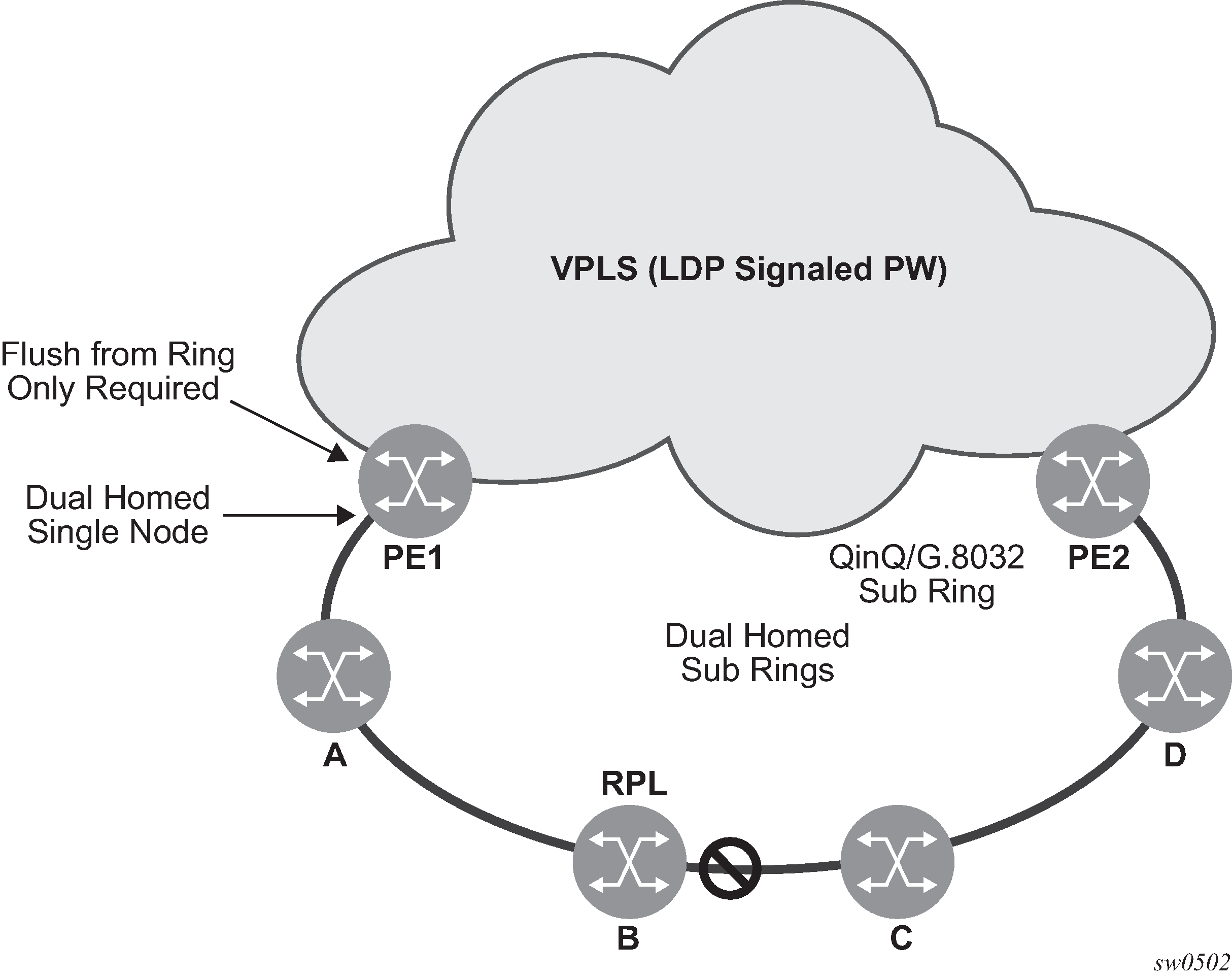
The following is a sample sub-ring using non-virtual link configuration output on PE1, the interconnecting node.
eth-ring 1
      description "Ethernet Ring 1"
      guard-time 20
      no revert-time
      rpl-node nbr
      sub-ring non-virtual-link
          interconnect vpls // VPLS is interconnection type
              propagate-topology-change
          exit
      exit
      path a 1/1/3 raps-tag 1.1
          description "Ethernet Ring: 1 Path on LAG"
          eth-cfm
          mep 8 domain 1 association 8
               ccm-enable
               control-mep
               no shutdown
            exit
        exit
        no shutdown
    exit
    no shutdown
exit
All the sub-ring nodes that are part of a sub-ring with non-virtual link should be configured with the sub-ring non-virtual-link option, as shown in the following sample configuration.
eth-ring 1
        sub-ring non-virtual-link
        exit
        path a 1/1/1 raps-tag 1.1
            eth-cfm
                mep 5 domain 1 association 4
                    ccm-enable
                    control-mep
                    no shutdown
                exit
            exit
            no shutdown
        exit
        path b 1/1/2 raps-tag 1.1
            eth-cfm
                mep 6 domain 1 association 3
                    ccm-enable
                    control-mep
                    no shutdown
                exit
            exit
            no shutdown
        exit
        no shutdown
    exit

# Control Channel for Sub-Ring using non-virtual-link on interconnecting node:

vpls 1 customer 1 create
      description "Ring 1 Control termination"
      stp shutdown
      sap 1/1/3:1.1 eth-ring 1 create //path a control
          stp shutdown
      exit
      no shutdown
  exit

# Configuration for the ring data into the VPLS Service

  vpls 5 customer 1 create
      description "VPLS Service at PE1"
      stp
          no shutdown
      exit
      sap 1/1/3:2.2 eth-ring 1 create
          stp shutdown
      exit
      sap 1/1/5:1 create
      exit
      mesh-sdp 5001:5 create //sample LDP MPLS LSPs
      exit
      mesh-sdp 5005:5 create
      exit
      mesh-sdp 5006:5 create
      exit

      no shutdown
  exit

# Control Channel for Sub-Ring using non-virtual-link on sub-Ring nodes:

vpls 1 customer 1 create
            stp
                shutdown
            exit
            sap 1/1/1:1.1 eth-ring 1 create
                stp
                    shutdown
                exit
            exit
            sap 1/1/2:1.1 eth-ring 1 create
                stp
                    shutdown
                exit
            exit
            no shutdown
        exit
The following is a sample sub-ring using non-virtual link configuration output homed to a major ring.
eth-ring 1
      description "Ethernet Ring 1"
      guard-time 20
      no revert-time
      rpl-node nbr
      sub-ring non-virtual-link
          interconnect ring-id <major ring index>
              propagate-topology-change
          exit
      exit
      path a 1/1/3 raps-tag 1.1
          description "Ethernet Ring : 1 Path on LAG"
          eth-cfm
          mep 8 domain 1 association 8
               ccm-enable
               control-mep
               no shutdown
            exit
        exit
        no shutdown
    exit
    no shutdown
exit
Lag support
The 7210 SAS does not support G.8032 Ethernet rings on LAGs.
OAM considerations
Ethernet CFM can be enabled on each individual path under an Ethernet ring. Only Down MEPs can be configured on each path and CCM sessions can be enabled to monitor the liveliness of the path using an interval of 100 ms. Different CCM intervals can be supported on path A and path B in an Ethernet ring. CFM is optional if hardware supports LOS for example.
Up MEPs on service SAPs that multicast into the service and monitor the active path may be used to monitor services.
QoS considerations
When Ethernet ring is configured on two ports located on different IOMs, the SAP queues and virtual schedulers will be created with the actual parameters on each IOM.
Ethernet ring CC messages transmitted over the SAP queues using the default egress QoS policy will use NC (network class) as a forwarding class. If user traffic is assigned to the NC forwarding class, it will compete for the same bandwidth resources with the Ethernet CCMs. Because CCM loss could lead to unnecessary switching of the Ethernet ring, congestion of the queues associated with the NC traffic should be avoided. The operator must configure different QoS policies to avoid congestion for the CCM forwarding class by controlling the amount of traffic assigned into the corresponding queue.
See the 7210 SAS-Mxp, S, Sx, T Services Guide for more information about Ethernet ring applicability in the services solution.
Support service and solution combinations
Ethernet rings are a supported Layer 2 service. The following considerations apply:
Only ports in access mode can be configured as Ethernet-ring paths.
Dot1q and QinQ ports are supported as Ethernet-ring path members.
A mix of regular and multiple Ethernet-ring SAPs and PWs can be configured in the same services.
Configuration guidelines for G.8032
The configuration guidelines for G.8032 are the following:
For 7210 SAS-T devices in network mode, users must enable the fast-flood feature and allocate the resources from the ingress-internal-tcam pool using the config system resource-profile g8032-fast-flood-enable command.
For 7210 SAS-T devices in access-uplink mode, users do not need to enable the fast-flood feature or allocate the resources from the ingress-internal-tcam pool using the config system resource-profile g8032-fast-flood-enable command, because the resources are automatically allocated by the software.
For 7210 SAS-Mxp devices in network mode, the fast-flood feature is enabled by default to improve the service fail-over time caused by failures in the ring path. If a failure is detected in one of the paths of the Ethernet ring, along with MAC flush, the system also floods the traffic to the available path. No explicit user configuration is required to facilitate this, and resource allocation from the ingress-internal-tcam pool is not needed.
For 7210 SAS-Sx/S 1/10GE and 7210 SAS-Sx 10/100GE, no explicit user configuration is needed to enable G.8032 fast-flood, and resources do not need to be allocated from the ingress-internal-tcam pool.
Service-level MEPs are not available on SAPs tied to an Ethernet-ring instance on a port.
G.8032 instances cannot be configured over a LAG.
G.8032 version 2 is the supported version, by default. Use the config eth-ring compatible-version command to change the G.8032 version to 1, if required. See the 7210 SAS-Mxp, R6, R12, S, Sx, T Interface Configuration Guide for more information.
Service creation process overview
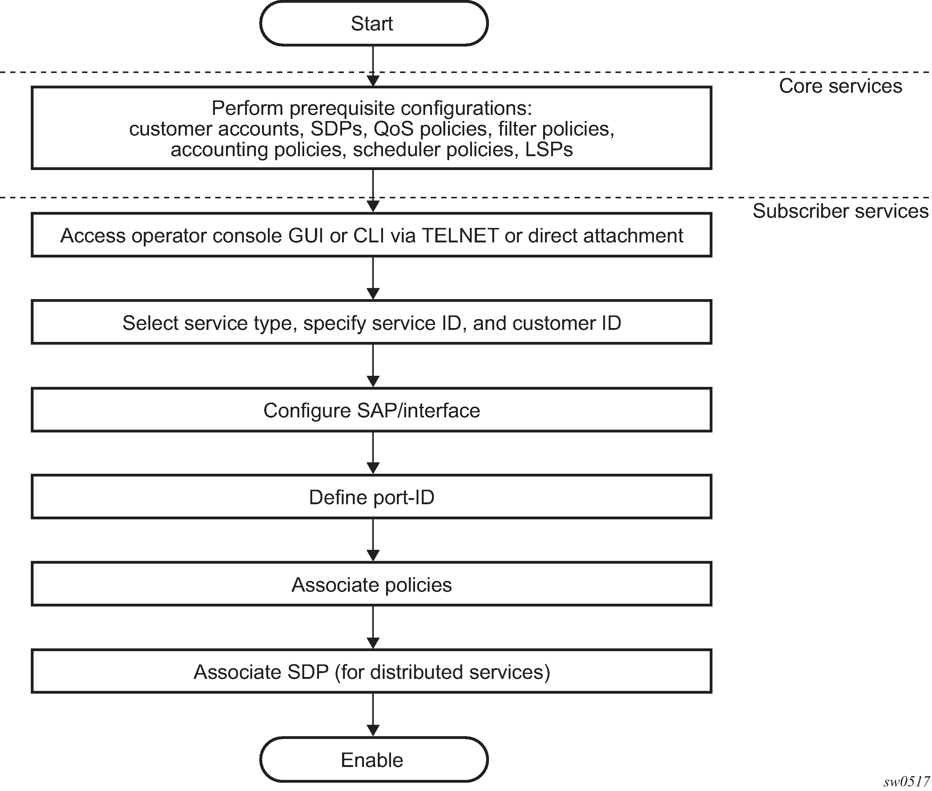
The following figure shows the overall process to provision core and subscriber services.
Deploying and provisioning services
The service model provides a logical and uniform way of constructing connectivity services. The basic steps for deploying and provisioning services can be broken down into three phases:
core network construction
service administration
service provisioning
Phase 1: core network construction
Before the services are provisioned, perform the following tasks:
Build the IP or IP/MPLS core network.
Configure routing protocols.
Configure MPLS LSPs (if MPLS is used).
Phase 2: service administration
Perform the following tasks to complete preliminary policy configurations to control traffic flow, operator access, and to manage fault conditions and alarm messages. Perform the following tasks:
Configure group and user access privileges.
Build templates for QoS, filter and accounting policies needed to support the core services.
Phase 3: service provisioning
Perform the following tasks to complete service provisioning:
Provision customer account information.
If necessary, build any customer-specific QoS, filter, or accounting policies.
Provision the customer services on the service edge routers by defining SAPs, and binding policies to the SAPs.
Configuration notes
This section describes service configuration restrictions.
General
Service provisioning tasks can be logically separated into two main functional areas, core tasks and subscriber services tasks, and are typically performed before provisioning a subscriber service.
Core tasks include the following:
Create customer accounts.
Create template QoS, filter, scheduler, and accounting policies.
Create SDPs (not applicable for devices configured in access-uplink mode).
Subscriber services tasks include the following:
Create Epipe and VPLS services.
Create a VPRN service (supported only when operating in network mode).
Bind SDPs (not applicable for 7210 SAS devices configured in access-uplink mode).
Configure interfaces (where required) and SAPs.
Create exclusive QoS and filter policies.
To send and receive inband management traffic (for 7210 SAS configured in access-uplink mode), create an IES service.
Configuring global service entities with CLI
This section provides information to create subscriber (customer) accounts using the command line interface.
Service model entities
The Nokia service model uses logical entities to construct a service. The service model contains four main entities to configure a service.
Basic configuration
The most basic service configuration must have the following:
a customer ID
a service type
a service ID
a SAP identifying a port and encapsulation value
an associated SDP for distributed services in the network mode
The SDPs are not supported in the access-uplink mode.
The following is a sample Epipe service configuration output showing the SDP and Epipe service entities. SDP ID 1 was created with the far-end node 10.20.1.2. Epipe ID 101 was created for customer ID 1, which uses the SDP ID 1.
A:ALA-7210M>config>service#
------------------------------------------
...
        sdp 1 mpls create
            description "Default sdp description"
            far-end 10.20.1.2
            lsp "lsp_1_to_B"
            signaling tldp
            no vlan-vc-etype
            path-mtu 9194
            no adv-mtu-override
            keep-alive
                shutdown
                hello-time 10
                hold-down-time 10
                max-drop-count 3
                timeout 5
                no message-length
            exit
            no collect-stats
            no accounting-policy
            no shutdown
        exit
...
    epipe 101 customer 1 vpn 101 create
            description "Default epipe description for service id 101"
            service-mtu 9194
            sap lag-2:101 create
                description "Default sap description for service id 101"
                no tod-suite
                dot1ag
                exit
                ingress
                    qos 1
                    no filter
                exit
            spoke-sdp 101:101 vc-type ether create
                no vlan-vc-tag
                ingress
                    no vc-label
                exit
                egress
                    no vc-label
                exit
                no control-word
                no
                dot1ag
                    mep 1 domain 5 association 101 direction down
                        ccm-enable
                        no ccm-ltm-priority
                        low-priority-defect remErrXcon
                        no mac-address
                        no shutdown
                    exit
                    mep 1 domain 6 association 101 direction down
                        ccm-enable
                        no ccm-ltm-priority
                        low-priority-defect remErrXcon
                        no mac-address
                        no shutdown
                    exit
                exit
                no collect-stats
                no accounting-policy
                no precedence
                no shutdown
            exit
            no shutdown
...
------------------------------------------
A:ALA-7210M>config>service#
Common configuration tasks
This section provides a brief overview of the tasks that must be performed to configure a customer account and an SDP.
Configuring customers accounts
The most basic customer account must have a customer ID. Optional parameters include:
description
contact name
telephone number
Customer information
Use the following syntax to create and input customer information.
config>service# customer customer-id create
    contact contact-information
    description description-string
    phone phone-number
The following is a sample basic customer account configuration output.
A:ALA-12>config>service# info
-------------------------------------------
...
       customer 5 create
           description "Nokia Customer"
           contact "Technical Support"
           phone "650 555-5100"
       exit
...
-------------------------------------------
A:A:ALA-12>config>service#
Configuring an SDP
SDPs are supported by all 7210 SAS platforms as described in this document, except those operating in access-uplink mode.
The most basic SDP must have the following:
a locally unique SDP identification (ID) number
the system IP address of the far-end routers
an SDP encapsulation type, MPLS
SDP configuration tasks
This section provides a brief overview of the tasks that must be performed to configure SDPs, and provides the CLI commands.
Consider the following SDP characteristics:
-
SDPs can be created as MPLS.
-
Each distributed service must have an SDP defined for every remote router to provide VLL, VPLS, and VPRN services.
-
A distributed service must be bound to an SDP. By default, no SDP is associated with a service. When an SDP is created, services can be associated with that SDP.
-
An SDP is not specific or exclusive to any one service or any type of service. An SDP can have more than one service bound to it.
-
The SDP IP address must be a 7210 SAS-series system IP address.
-
To configure an MPLS SDP, LSPs must be configured first, then the LSP-to-SDP association must be explicitly created.
-
In the SDP configuration, automatic ingress and egress labeling (targeted LDP) is enabled by default. Ingress and egress VC labels are signaled over a TLDP connection between two 7210 SAS-series routers.
If signaling is disabled for an SDP, services using that SDP must configure ingress and egress VC labels manually.
To configure a basic SDP, perform the following steps:
-
Specify an originating node.
-
Create an SDP ID.
-
Specify an encapsulation type.
-
Specify a far-end node.
Configuring an SDP
Use the following syntax to create an SDP and select an encapsulation type. Only MPLS encapsulation is supported.
When you specify the far-end IP address, you are creating the tunnel; in essence, you are creating the path from point A to point B. When you configure a distributed service, you must identify an SDP ID. Use the show service sdp command to display the qualifying SDPs.
When specifying MPLS SDP parameters, you must specify an LSP. If an LSP name is specified, RSVP is used for dynamic signaling within the LSP.
LSPs are configured in the config>router>mpls context. See the 7210 SAS-Mxp, R6, R12, S, Sx, T MPLS Guide for configuration and command information.
Use the following syntax to create an MPLS SDP.
config>service>sdp sdp-id [mpls] create
    adv-mtu-override
    description description-string
    far-end ip-address
    keep-alive
    hello-time seconds
    hold-down-time seconds
    max-drop-count count
    message-length octets
    timeout timeout
    no shutdown
            lsp lsp-name [lsp-name](only for MPLS SDPs)
    path-mtu octets
    signaling {off | tldp}
    no shutdown
The following is a sample LSP-signaled MPLS SDP configuration output.
A:ALA-12>config>service# info
-------------------------------------------
...
        sdp 8 mpls create
            description "MPLS-10.10.10.104"
            far-end 10.10.10.104
            lsp "to-104"
            keep-alive
            mixed-lsp-mode
                revert-time 1
                shutdown
            exit
            no shutdown
        exit
...
-----------------------------------------
A:ALA-12>config>service#
Configuring a mixed-LSP SDP
The following is the command usage to configure an SDP with mixed-LSP mode of operation:
config>service>sdp mpls>mixed-lsp-mode
The primary is backed up by the secondary. Two combinations are possible: the primary of RSVP is backed up by LDP and the primary of LDP is backed up by 3107 BGP.
The no form of this command disables the mixed-LSP mode of operation. The user first has to remove one of the LSP types from the SDP configuration or the command will fail.
The user can also configure how long the service manager must wait before it reverts the SDP to a higher priority LSP type, when it becomes available, by using the following command:
config>service>sdp mpls>mixed-lsp-mode>revert-time revert-time
An infinite value for the timer dictates that the SDP must never revert to another higher priority LSP type unless the currently active LSP type is down:
config>service>sdp mpls>mixed-lsp-mode>revert-time infinite
The BGP LSP type is allowed. The bgp-tunnel command can be configured under the SDP with the lsp or ldp commands.
Ethernet connectivity fault management
Ethernet Connectivity Fault Management (ETH-CFM) is defined in two similar standards: IEEE 802.1ag and ITU-T Y.1731. Both standards specify protocols, procedures, and managed objects to support transport fault management, including discovery and verification of the path, detection and isolation of a connectivity fault for each Ethernet service instance.
ETH-CFM configuration is split into multiple CLI contexts. The ETH-CFM configuration, which defines the different management constructs and administrative elements, is performed in the eth-cfm context. The individual management points are configured within the specific service contexts in which they are applied (port, SAP, and so on).
See the 7210 SAS-Mxp, S, Sx, T Services Guide for detailed information about the basic service-applicable material to build the service-specific management points, MEPs, and MIPs. The different service types support a subset of the features from the complete ETH-CFM suite.
Ethernet continuity check (ETH-CC) used for continuity is available to all MEPs configured within a service. 7210 SAS devices support Down MEPs and UP MEPs, though the support is not available on all platforms. See the 7210 SAS-Mxp, R6, R12, S, Sx, T OAM and Diagnostics Guide for more information.
The troubleshooting tools ETH-LBM, ETH-LBR, LTM ETH-TST, and LTR ETH-TST, defined by the IEEE 802.1ag specification and the ITU-T Y.1731 recommendation, are applicable to all MEPs (and MIPs where appropriate).The advanced notification function, Alarm Indication Signal (AIS), defined by the ITU-T Y.1731, is supported on Epipe services.
The advanced performance functions, 1DM, DMM/DMR, and SLM/SLR are supported on all service MEPs.
See the 7210 SAS-Mxp, R6, R12, S, Sx, T OAM and Diagnostics Guide for a description of the individual features and functions that are supported and configuration guidelines applicable to CFM entities on the 7210 SAS.
The following table lists ETH-CFM acronym expansions.
Acronym |
Expansions |
|---|---|
1DM |
One-way Delay Measurement (Y.1731) |
AIS |
Alarm Indication Signal |
BNM |
Bandwidth Notification Message (Y.1731 sub OpCode of GMN) |
CCM |
Continuity Check Message |
CFM |
Connectivity Fault Management |
DMM |
Delay Measurement Message (Y.1731) |
DMR |
Delay Measurement Reply (Y.1731) |
GMN |
Generic Message Notification |
LBM |
Loopback Message |
LBR |
Loopback Reply |
LTM |
Linktrace Message |
LTR |
Linktrace Reply |
ME |
Maintenance Entity |
MA |
Maintenance Association |
MA-ID |
Maintenance Association Identifier |
MD |
Maintenance Domain |
MEP |
Maintenance Association Endpoint |
MEP-ID |
Maintenance Association Endpoint Identifier |
MHF |
MIP Half Function |
MIP |
Maintenance Domain Intermediate Point |
OpCode |
Operational Code |
RDI |
Remote Defect Indication |
TST |
Ethernet Test (Y.1731) |
SLM |
Synthetic Loss Message (Y.1731) |
SLR |
Synthetic Loss Reply (Y.1731) |
MA, MEP, MIP, and MD levels
ETH-CFM capabilities may be deployed in many different Ethernet service architectures. The Ethernet-based SAPs and SDP bindings provide the endpoint on which the management points may be created. The basic functions can be used in different services, VPLS and Epipe. The following figures show two possible example scenarios for ETH-CFM deployment in Ethernet access and aggregation networks.
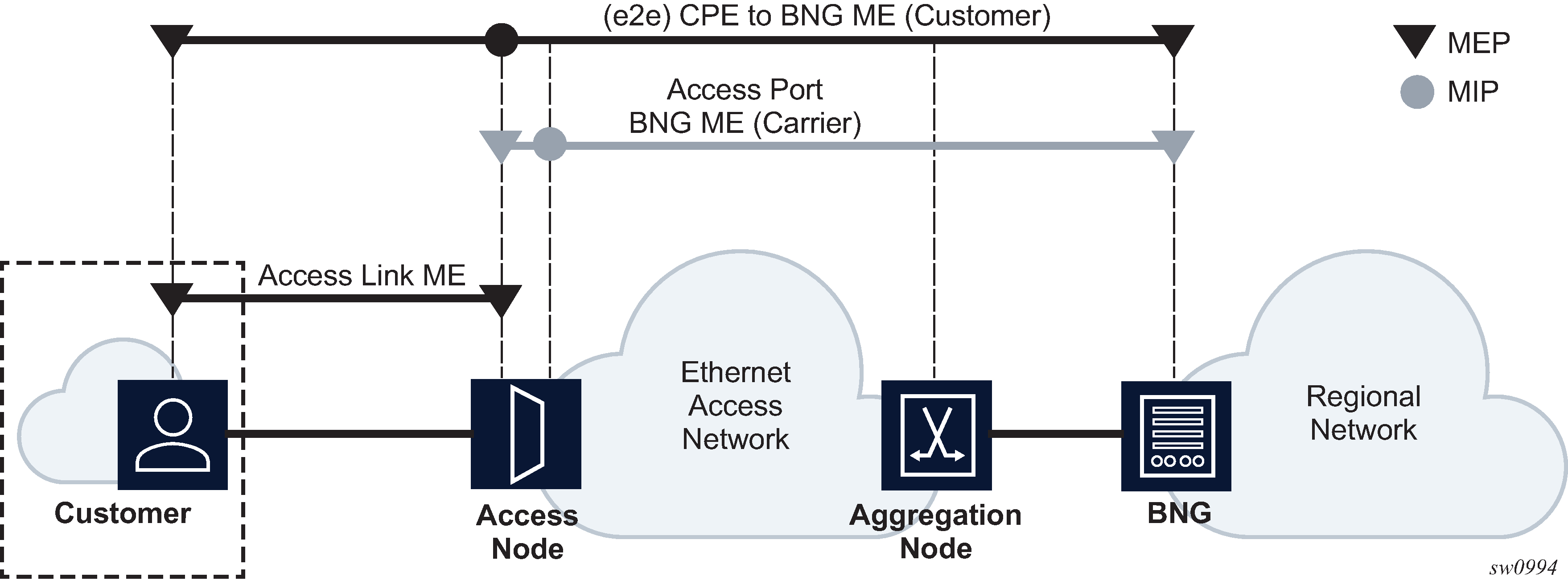
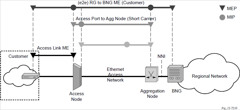
The following functions are supported:
CFM can be enabled or disabled on a SAP or SDP bindings basis.
The eight ETH-CFM levels are suggested to be broken up numerically between customer 7-5, service provider 4-3 and operator 2-1. Level 0 typically is meant to monitor direct connections without any MIPs and should be reserved for port-based G8032 MEPs.
Down MEP and UP MEP with an MEP-ID on a SAP/SDP binding for each MD level can be configured, modified, or deleted. Each MEP is uniquely identified by the MA-ID, MEP-ID tuple:
MEP creation on a SAP is allowed only for Ethernet ports (with null, q-tags, QinQ encapsulations).
MEP support in different services and the endpoints configured in the services (SAPs, SDPs, IP interfaces, and so on) varies across services and 7210 SAS platforms.
MIP creation on a SAP for each MD level can be enabled and disabled. MIP creation is automatic or manual when it is enabled. When MIP creation is disabled for an MD level, the existing MIP is removed. 7210 SAS platforms have the notion of ingress and egress MIPs. Ingress MIP responds to OAM messages that are received. Egress MIP responds to OAM messages that are sent. Ingress and egress MIP support for SAP, SDP bindings, and services varies and is listed in Defect conditions and priority settings. See MEP and MIP support for more information about MEP and MIP support.
Common actionable failures
It is important to note that AIS operates independently from the low-priority-defect setting. The low-priority-defect setting configuration parameter affects only the ETH-CFM fault propagation and alarming outside the scope of AIS. Any fault in the MEP state machine generates AIS when it is configured. The following table describes the ETH-CC defect condition groups, configured low-priority-defect setting, priority, and defect as it applies to fault propagation.
Defect |
Low priority defect |
Description |
Causes |
Priority |
|---|---|---|---|---|
DefNone |
N/A |
No faults in the association |
Normal operations |
N/A |
DefRDICCM |
allDef |
Remote Defect Indication |
Feedback mechanism to inform that unidirectional faults exist. It provides the feedback loop to the node with the unidirectional failure conditions. |
1 |
DefMACStatus (default) |
macRemErrXcon |
MAC Layer |
Remote MEP is indicating that a remote port or interface is not operational. |
2 |
DefRemoteCCM |
remErrXon |
No communication from remote peer |
MEP is not receiving CCM from a configured peer. The timeout of CCM occurs at 3.5 times the local CC interval. As per the specification, this value is not configurable. |
3 |
DefErrorCCM |
errXcon |
Remote and local configurations do not match required parameters |
Caused by different interval timer, domain-level issues (lower value arriving at a MEP configured with a higher value), MEP receiving CCM with its MEPID |
4 |
DefXconn |
Xcon |
Cross connected service |
The service is receiving CCM packets from a different association. This could indicate that two services have merged or there is a configuration error on one of the SAPs or bindings of the service, incorrect association identification. |
5 |
MEP and MIP support
See the 7210 SAS-Mxp, R6, R12, S, Sx, T OAM and Diagnostics Guide for more information about ETH-CFM support for different services and endpoints.
Configuring ETH-CFM parameters
See the 7210 SAS-Mxp, R6, R12, S, Sx, T OAM and Diagnostics Guide for more information about ETH-CFM configuration guidelines for 7210 SAS platforms.
Configuring ETH-CFM requires commands at two different hierarchy levels of the CLI.
This section provides a sample of the global ETH-CFM configuration, which defines the domains, associations, linkage of the service ID or function, and the globally applicable CCM parameters, including the interval and building of the remote MEPs database.
The following is a sample configuration output.
*A:ALU-7_A>config>eth-cfm# info
----------------------------------------------
        domain 1 name "1" level 1
            association 2 name "1345"
                bridge-identifier 100
                exit
                ccm-interval 60
                remote-mepid 2
                remote-mepid 3
            exit
        exit
----------------------------------------------
*A:ALU-7_A>config>eth-cfm#
Defining the MEP and configuring service-specific ETH-CFM parameters is performed within the service on the specific SAP or SDP binding. The following is sample output using the service VPLS 100 on the SAP.
#*A:ALU-7_A>config>service# info
----------------------------------------------
     vpls 100 customer 1 create
          description "VPLS service 100 - Used for MEP configuration example"
               sap 2/2/1:20 create
                    description "2/2/1:20"
                    eth-cfm
                         mep 1 domain 1 association 1 direction down
                              no shutdown
                         exit
                    exit
               exit
          exit
          no shutdown
          exit
          customer 1 create
               description "Default customer"
          exit
          exit
----------------------------------------------
*A:ALU-7_A>config>service#
The preceding samples were based on IEEE 802.1ag. They are not capable of running Y.1731 functions. To build a Y.1731 context, the domain format must be none.
The following are sample global ETH-CFM configuration outputs and the advanced Y.1731 functions that can be configured. The configuration will reject the configuration of Y.1731 functions within an IEEE 802.1ag context.
*A:7210-2# config>eth-cfm# info
----------------------------------------------
        domain 1 format none level 1
            association 1 format icc-based name "1234567890123"
                bridge-identifier 100
                exit
                ccm-interval 1
            exit
        exit


*A:7210-2# config>service# info
----------------------------------------------
        vpls 100 customer 1 create
            stp
                shutdown
            exit
            sap 2/2/1:40 create
                eth-cfm
                    mep 1 domain 1 association 1 direction up
                        ais-enable
                            priority 2
                            interval 60
                        exit
                        eth-test-enable
                            test-pattern all-ones crc-enable
                        exit
                        no shutdown
                    exit
                exit
            exit
            no shutdown
        exit
----------------------------------------------
-
To transmit and receive AIS PDUs, Y.1731 MEPs must have ais-enable configured.
-
To transmit and receive ETH-Test PDUs, Y.1731 MEPs must have eth-test-enable configured.
Applying ETH-CFM parameters
Use the following syntax to apply ETH-CFM parameters to the following entities.
config>service>epipe>sap
    eth-cfm
    mep mep-id domain md-index association ma-index [direction
    {up | down}]
            ais-enable
                client-meg-level [level [level ...]
                interval {1 | 60}
                priority priority-value
            ccm-enable
            ccm-ltm-priority priority
            eth-test-enable
                test-pattern {all-zeros | all-ones} [crc-enable]
            low-priority-defect {allDef | macRemErrXcon | remErrXcon | errXcon | xcon | noXcon}
            [no] shutdown
config>service>epipe>spoke-sdp
    eth-cfm
    mep mep-id domain md-index association ma-index [direction
    {up | down}]
        ccm-enable
        ccm-ltm-priority priority
        eth-test-enable
            test-pattern {all-zeros | all-ones} [crc-enable]
        low-priority-defect {allDef|macRemErrXcon|remErrXcon|
            errXcon|xcon|noXcon}
        [no] shutdown
config>service>vpls>sap
    eth-cfm
    mip
    mep mep-id domain md-index association ma-index [direction {up | down}]
    no mep mep-id domain md-index association ma-index
        ccm-enable
        ccm-ltm-priority priority
        eth-test-enable
            test-pattern {all-zeros | all-ones} [crc-enable]
        low-priority-defect {allDef|macRemErrXcon|remErrXcon|errXcon|xcon|noXcon}
        mac-address mac-address
        [no] shutdown
config>service>vpls>mesh-sdp sdp-id[:vc-id] [vc-type {ether|vlan}]
    eth-cfm
    mep mep-id domain md-index association ma-index [direction
    {up | down}]
        ccm-enable
        ccm-ltm-priority priority
        eth-test-enable
            test-pattern {all-zeros | all-ones} [crc-enable]
        low-priority-defect {allDef|macRemErrXcon|remErrXcon|
        errXcon|xcon|noXcon}
        mac-address mac-address
        no] shutdown
config>service>vpls
    spoke-sdp sdp-id:vc-id [vc-type {ether | vlan}] [split-horizon-group group-name] [no-endpoint]
    spoke-sdp sdp-id:vc-id [vc-type {ether | vlan}] [split-horizon-group group-name] endpoint endpoint
    eth-cfm
    map mep-id domain md-index association ma-index [direction
    {up | down}]
        ccm-enable
        ccm-ltm-priority priority
        eth-test-enable
            test-pattern {all-zeros | all-ones} [crc-enable]
        low-priority-defect {allDef | macRemErrXcon|remErrXcon|errXcon|xcon|noXcon}
        mac-address mac-address
        no] shutdown
oam
    eth-cfm linktrace mac-address mep mep-id domain md-index association ma-index [ttl ttl-value]
    eth-cfm loopback mac-address mep mep-id domain md-index association ma-index [send-count send-count] [size data-size] [priority priority]
    eth-cfm eth-test mac-address mep mep-id domain md-index association ma-index [priority priority] [data-length data-length]
    eth-cfm one-way-delay-test mac-address mep mep-id domain md-index association ma-index [priority priority]
    eth-cfm two-way-delay-test mac-address mep mep-id domain md-index association ma-index [priority priority]
    eth-cfm two-way-slm-test mac-address mep mep-id domain md-index association ma-index [priority priority]
Layer 2 control processing
Operators providing the Epipe service must be able to transparently forward Layer 2 control frames received from the customers. This allows their customers to run these control protocols between the different locations that are part of the Layer 2 VPN service. The 7210 SAS platforms provide the user with the following capability:
an option to tunnel, discard, or peer for EFM OAM, LLDP, dot1x, and LACP
BPDU translation and Layer 2 protocol tunneling support for xSTP and Cisco control protocols. This is supported only in a VPLS service.
See L2PT and BPDU translation for more information.
The CDP, VTP, DTP, PAgP, and UDLD management protocols are forwarded transparently in an Epipe service.
By default, LACP, LLDP, EFM OAM, and dot1x Layer 2 control protocol untagged packets are discarded if the protocol is not enabled on the port where these frames are received. The user has an option to enable peering by enabling the protocol on the port and configuring the appropriate parameters for the protocol. The user also has an option to tunnel these packets using an Epipe or VPLS service.
In a VPLS service, the Layer 2 control frames are sent out of all the SAPs configured in the VPLS service. Nokia recommends using this feature carefully and only when a VPLS is used to emulate an end-to-end Epipe service (that is, an Epipe configured using a three-point VPLS service, with one access SAP and two access-uplink SAPs or SDPs for redundant connectivity). That is, if the VPLS service is used for multipoint connectivity, it is not recommended to use this feature. When a Layer 2 control frame is forwarded out of a dot1q SAP or a QinQ SAP, the SAP tags of the egress SAP are added to the packet.
The following SAPs can be configured for tunneling the untagged L2CP frames (corresponding protocol tunneling needs to be enabled on the port):
If the port encapsulation is null, the user has an option to tunnel these packets by configuring a null SAP on a port.
If the port encapsulation is dot1q, the user has an option to use dot1q explicit null SAP (for example, 1/1/10:0) or a dot1q default SAP (for example, 1/1/11:*) to tunnel these packets.
If the port encapsulation is QinQ, the user has an option to use 0.* SAP (for example, 1/1/10:0.*) to tunnel these packets.
In addition to the protocols listed previously, protocols that are not supported on the 7210 SAS (for example, GARP, GVRP, ELMI, and others) are transparently forwarded in case of a VPLS service. These protocols are transparently forwarded if a null SAP, dot1q default SAP, dot1q explicit null SAP or 0.* SAP is configured on the port and the received packet is untagged. If the received packet is tagged and matches the tag of any of the SAPs configured on the port, it is forwarded in the context of the SAP and the service. Otherwise, if the received packet is untagged and none of the null or dot1q default or dot1q explicit null or 0.* SAP is configured, it is discarded.
If a 7210 receives a tagged L2CP packet on any SAP (including null, dot1q, dot1q range, QinQ, QinQ default), it is forwarded transparently in the service similar to normal service traffic (xSTP processing behavior is different in VPLS service and is listed as follows).
The xSTP processing behavior in a VPLS service is as follows:
If xSTP is enabled in the service, and if the tag in the STP BPDU matches the tag of the configured SAP, the received xSTP BPDU is processed by the local xSTP instance on the node for that service when xSTP is enabled on the SAP, and discarded when xSTP is disabled on the SAP.
If the tags do not match, xSTP BPDU packets are transparently forwarded in the service similar to normal service traffic.
If xSTP is disabled in the service, STP BPDU packets are transparently forwarded in the service similar to normal service traffic.
The following table describes L2CP support for 7210 SAS-T, 7210 SAS-Sx/S 1/10GE, and 7210 SAS-Mxp access-uplink and network media platforms.
Table 7. L2CP support for 7210 SAS-T, 7210 SAS-Sx/S 1/10GE, 7210 SAS-Sx 10/100GE, and 7210 SAS-Mxp access-uplink and network mode platforms Packet type
7210 SAS-T
7210 SAS-Mxp
7210 SAS-Sx/S 1/10GE
7210 SAS-Sx 10/100GE
LACP
Option to tunnel or discard or peer
Option to tunnel or discard or peer
Option to tunnel or discard or peer
Option to tunnel or discard or peer
Dot1x
Option to tunnel or discard or peer
Option to tunnel or discard or peer
Option to tunnel or discard or peer
Option to tunnel or discard or peer
LLDP
Option to tunnel or discard or peer1
Option to tunnel or discard or peer1
Option to tunnel or discard or peer1
Option to tunnel or discard or peer1
EFM
Option to tunnel or discard or peer
Option to tunnel or discard or peer
Option to tunnel or discard or peer
Option to tunnel or discard or peer
L2PT
Supported2
Supported2
Supported2
Supported2
BPDU Tunneling
Supported
Supported
Supported
Supported
xSTP
Option to peer or tunnel
Option to peer or tunnel
Option to peer or tunnel
Option to peer or tunnel
Service management tasks
This section describes the service management tasks.
Modifying customer accounts
To access a specific customer account, you must specify the customer ID.
Use the following syntax to display a list of customer IDs.
Enter the parameter (description, contact, phone) and then enter the new information.
config>service# customer customer-id create
    [no] contact contact-information
    [no] description description-string
    [no] phone phone-number
- Example:
config>service# customer 27 create
    config>service>customer$ description ‟Western Division”
    config>service>customer# contact ‟John Dough”
    config>service>customer# no phone ‟(650) 237-5102”
Deleting customers
The no form of the customer command removes a customer ID and all associated information. All service references to the customer must be shut down and deleted before a customer account can be deleted.
config>service# no customer customer-id
- Example:
config>service# epipe 5 customer 27 shutdown
    config>service# epipe 9 customer 27 shutdown
    config>service# no epipe 5
    config>service# no epipe 9
    config>service# no customer 27
Modifying SDPs
SDPs are supported by all 7210 SAS platforms as described in this document, except those operating in access-uplink mode.
To access a specific SDP, you must specify the SDP ID. To display a list of SDPs, use the show service sdp command. Enter the parameter, such as description, far-end, and lsp, and then enter the new information.
When an SDP is created, the SDP encapsulation type cannot be modified.
config>service# sdp sdp-id
- Example:
config>service# sdp 79
    config>service>sdp# description ‟Path-to-107”
    config>service>sdp# shutdown
    config>service>sdp# far-end ‟10.10.10.107”
    config>service>sdp# path-mtu 1503
    config>service>sdp# no shutdown
Deleting SDPs
The no form of the sdp command removes an SDP ID and all associated information. Before an SDP can be deleted, the SDP must be shutdown and removed (unbound) from all customer services where it is applied.
config>service# no sdp 79
- Example:
config>service# epipe 5 spoke-sdp 79:5
    config>service>epipe>sdp# shutdown
    config>service>epipe>sdp# exit
    config>service>epipe# exit
    config>service# no sdp 79
Global services command reference
Command hierarchies
Global service configuration commands
Customer commands
config
    - service
        - [no] customer customer-id
            - contact contact-information
            - no contact
            - description description-string
            - no description
            - [no] phone phone-number
Pseudowire (PW) commands
PW commands are supported on all 7210 SAS platforms as described in this document, except those operating in access-uplink mode.
config
    - service
        - pw-routing
            - boot-timer secs
            - no boot-timer
            - local-prefix local-prefix [create]
            - no local-prefix local-prefix
                - advertise-bgp route-distinguisher rd [community community]
                -  no advertise-bgp route-distinguisher rd [community community]
            - path name [create]
            - no path name
                - hop hop-index ip-address
                - no hop hop-index
                - [no] shutdown
            - retry-count [10..10000]
            - no retry-count
            - retry-timer secs
            - no retry-timer
            - spe-address global-id:prefix
            - no spe-address
            - [no] static-route route-name
config
    - service
        - [no] pw-template policy-id [use-provisioned-sdp] [create]
            - accounting-policy acct-policy-id
            - no accounting-policy
            - [no] collect-stats
            - [no] control-word
            - [no] disable-learning
            - [no] disable-aging
            - [no] discard-unknown-source
            - [no] force-vlan-vc-forwarding
            - hash-label [signal-capability]
            - no hash-label
            - igmp-snooping
                - [no] disable-router-alert-check
                - import policy-name
                - no import
                - last-member-query-interval 1/10 seconds
                - no last-member-query-interval
                - max-num-groups max-num-groups
                - no max-num-groups
                - query-interval seconds
                - no query-interval
                - query-response-interval seconds
                - no query-response-interval
                - robust-count robust-count
                - no robust-count
                - [no] send-queries
                - version version
                - no version
            - limit-mac-move {blockable | non-blockable}
            - no limit-mac-move
            - [no] mac-pinning
            - max-nbr-mac-addr table-size
            - no max-nbr-mac-addr
            - split-horizon-group group-name
            - no split-horizon-group
                - description description-string
                - no description
            - vc-type {ether | vlan}
            - vlan-vc-tag 0..4094
            - no vlan-vc-tag
SDP commands
SDP commands are supported on all 7210 SAS platforms as described in this document, except those operating in access-uplink mode.
config
    - service
        - sdp sdp-id [mpls] [create]
        - no sdp sdp-id
            - accounting-policy acct-policy-id
            - no accounting-policy
            - collect-stats acct-policy-id
            - no collect-stats
            - [no] adv-mtu-override
            - [no] bgp-tunnel
            - [no] collect-stats
            - description description-string
            - no description
            - far-end ip-address | ipv6-address
            - no far-end[ip-address | ipv6-address]
            - keep-alive
                - hello-time seconds
                - no hello-time
                - hold-down-time seconds
                - no hold-down-time
                - max-drop-count count
                - no max-drop-count
                - message-length octets
                - no message-length
                - [no] shutdown
                - timeout timeout
                - no timeout
            - [no] ldp
            - metric metric
            - no metric
            -  no mixed-lsp-mode
            - mixed-lsp-mode
                - no revert-time
                - revert-time {revert-time |infinite}
            - [no] lsp lsp-name
            - path-mtu octets
            - no path-mtu
            - [no] shutdown
            - signaling [off | tldp | bgp]
            - [no] sr-isis
            - [no] sr-ospf
SAP commands for 7210 SAS platforms operating in network mode
config
    - service
        - epipe
            - sap sap-id [create]
            - no sap sap-id
        - ies
            - sap sap-id [create]
            - no sap sap-id
        - vpls
            - sap sap-id [split-horizon-group group-name] [eth-ring ring-index] [create]
            - no sap sap-id
        - vprn
            - interface ip-int-name  [create]
            - no interface ip-int-name
                - sap sap-id [create]
                - no sap sap-id
SAP commands for 7210 SAS platforms operating in access-uplink mode
config
    - service
        - epipe service-id [customer customer-id] [create] [svc-sap-type {null-star | dot1q-preserve|any|dot1q-range}] [customer-vid vlan-id]
        - no epipe service-id
            - sap sap-id [create]
            - no sap sap-id
        - ies service-id [customer customer-id] [create]
        - no ies service-id
            - sap sap-id [create]
            - no sap sap-id
        - vpls service-id [customer customer-id] [create] [vpn vpn-id] [m-vpls] [svc-sap-type {nullstar | any | dot1q-preserve}] [customer-vid vlan-id]
        - no vpls service-id
            - sap sap-id [create]
            - no sap sap-id
ETH-CFM configuration commands
For command descriptions, refer to the 7210 SAS-Mxp, R6, R12, S, Sx, T OAM and Diagnostics Guide.
config
    - eth-cfm
        - domain md-index [format md-name-format] [name md-name] level level
        - domain md-index
        - no domain md-index
            - association ma-index [format ma-name-format] name ma-name
            - association ma-index
            - no association ma-index
                - [no] bridge-identifier bridge-id
                    - id-permission {chassis}
                    - no id-permission
                    - mhf-creation {none | explicit | default | static}
                    - no mhf-creation
                    - mip-ltr-priority priority
                    - vlan vlan-id
                    - no vlan
                - ccm-interval {10ms | 100ms | 1 | 10 | 60 | 600}
                - no ccm-interval
                - [no] remote-mepid mep-id
        - slm
            - inactivity-timer timer
            - no inactivity-timer
        - system
            - sender-id local local-name
            - sender-id system
            - no sender-id
Show commands
show
    - service
        - customer [customer-id] [site customer-site-name]
        - sdp sdp-id keep-alive-history
        - sdp far-end ip-address keep-alive-history
        - sdp [sdp-id] [detail]
        - sdp far-end ip-address [detail]
        - sdp-using [sdp-id[:vc-id] | far-end ip-address]
        - service-using [epipe] [vpls] [mirror] [customer customer-id]
    - eth-ring [status]
    - eth-ring ring-index hierarchy
    - eth-ring ring-index [path {a | b}]
    - eth-cfm
        - association [ma-index] [detail]
        - cfm-stack-table [port port-id [vlan vlan-id]] [level 0..7] [direction down]
        - cfm-stack-table
        - cfm-stack-table port port-id [all-ports] [level 0..7] [direction down]
        - cfm-stack-table port port-id [vlan qtag[.qtag]] [level 0..7] [direction down]
        - mep mep-id domain md-index association ma-index [loopback] [linktrace]
        - mep mep-id domain md-index association ma-index  remote-mepid mep-id | all-remote-mepids
        - mep mep-id domain md-index association ma-index eth-test-results [remote-peer mac-address]
        - mep mep-id domain md-index association ma-index one-way-delay-test [remote-peer mac-address]
        - mep mep-id domain md-index association ma-index two-way-delay-test [remote-peer mac-address]
        - mep mep-id domain md-index association ma-index two-way-slm-test [remote-peer macaddress]
        - pw-routing {local-prefix | static-route | paths | all}
        - pw-routing route-table [all-routes]
        - pw-routing route-table summary
        - pw-template
Tools commands
tools
    - perform
        - service
            - eval-pw-template policy-id [allow-service-impact]
            - id service-id
                - endpoint endpoint-name
                    - force-switchover sdp-id:vc-id
                    - no force-switchover
                    - force-switchover spoke-sdp-fec [1..4294967295]
                - eval-pw-template policy-id [allow-service-impact]
            - eval-expired-fec
                - eval-expired-fec spoke-sdp-fec-id
                - eval-expired-fec all
            - spoke-sdp-fec-release global-id[:prefix[:ac-id]]
Command descriptions
Global service configuration commands
Generic commands
description
Syntax
description description-string
no description
Context
config>service>customer
config>service>sdp (not supported in access-uplink mode)
Platforms
Supported on all 7210 SAS platforms as described in this document, including those operating in access-uplink mode.
Description
This command creates a text description stored in the configuration file for a configuration context.
The no form of this command removes the string from the configuration.
Default
No description associated with the configuration context.
Parameters
- string
Specifies the description character string. Allowed values are any string up to 80 characters composed of printable, 7-bit ASCII characters. If the string contains special characters (#, $, spaces, and so on), the entire string must be enclosed within double quotes.
shutdown
Syntax
[no] shutdown
Context
config>dot1ag>mep
config>service>sdp (not supported in access-uplink mode)
config>service>sdp>keep-alive (not supported in access-uplink mode)
Platforms
Supported on all 7210 SAS platforms as described in this document, including those operating in access-uplink mode.
Description
This command administratively disables an entity. When disabled, an entity does not change, reset, or remove any configuration settings or statistics.
The operational state of the entity is disabled as well as the operational state of any entities contained within. Many objects must be shut down before they may be deleted.
Services are created in the administratively down (shutdown) state. Default administrative states for services and service entities is described as follows in Special Cases.
The no form of this command places the entity into an administratively enabled state and then tries to enter the operationally up state.
Special Cases
- Service Admin State
Bindings to an SDP within the service are put into the out-of-service state when the service is shutdown. While the service is shutdown, all customer packets are dropped and counted as discards for billing and debugging purposes.
- SDP (global)
When an SDP is shutdown at the global service level, all bindings to that SDP are put into the out-of-service state and the SDP itself is put into the administratively and operationally down states. Packets that would be transmitted using this SDP binding are discarded and counted as dropped packets.
- SDP (service level)
Shutting down an SDP within a service only affects traffic on that service from entering or being received from the SDP. The SDP itself may still be operationally up for other services.
- SDP Keepalives
Enables SDP connectivity monitoring keepalive messages for the SDP ID. Default state is disabled (shutdown) in which case the operational state of the SDP-ID is not affected by the keepalive message state.
Customer management commands
customer
Syntax
customer customer-id [create]
no customer customer-id
Context
config>service
Platforms
Supported on all 7210 SAS platforms as described in this document, including those operating in access-uplink mode
Description
This command creates a customer ID and customer context used to associate information with a particular customer. Services can later be associated with this customer at the service level.
Each customer-id must be unique. The create keyword must follow each new customer customer-id entry.
Enter an existing customer customer-id (without the create keyword) to edit the customer parameters.
Default customer 1 always exists on the system and cannot be deleted.
The no form of this command removes a customer-id and all associated information. Before removing a customer-id, all references to that customer in all services must be deleted or changed to a different customer ID.
Default
customer 1
Parameters
- customer-id
Specifies the ID number to be associated with the customer, expressed as an integer.
contact
Syntax
contact contact-information
no contact contact-information
Context
config>service>customer
Platforms
Supported on all 7210 SAS platforms as described in this document, including those operating in access-uplink mode
Description
This command specifies contact information for a customer, such as a technician name or account contract name.
Default
no contact
The no form of this command removes the contact information from the customer ID.
Parameters
- contact-information
Specifies the customer contact information entered as an ASCII character string up to 80 characters. If the string contains special characters (#, $, spaces, and so on), the entire string must be enclosed within double quotes. Any printable, seven bit ASCII characters may be used within the string.
phone
Syntax
[no] phone string
Context
config>service>customer
Platforms
Supported on all 7210 SAS platforms as described in this document, including those operating in access-uplink mode
Description
This command specifies telephone number information for a customer ID.
The no form of this command removes the phone number value from the customer ID.
Parameters
- string
Specifies the customer phone number entered as an ASCII string, up to 80 characters. If the string contains special characters (#, $, spaces, and so on), the entire string must be enclosed within double quotes. Any printable, seven bit ASCII characters may be used within the string.
Pseudowire Commands
pw-routing
Syntax
pw-routing
Context
config>service
Platforms
Supported on all 7210 SAS platforms as described in this document, except those operating in access-uplink mode
Description
Commands in this context configure dynamic multi-segment pseudowire (MS-PW) routing. Pseudowire routing must be configured on each node that will be a T-PE or an S-PE.
Default
disabled
boot-timer
Syntax
boot-timer secs
no boot-timer
Context
config>service>pw-routing
Platforms
Supported on all 7210 SAS platforms as described in this document, except those operating in access-uplink mode
Description
This command configures a hold-off timer for MS-PW routing advertisements and signaling and is used at boot time.
The no form of this command removes a previously configured timer and restores it to its default.
Default
10
Parameters
- timer-value
The value of the boot timer in seconds.
local-prefix
Syntax
local-prefix local-prefix [create]
no local-prefix local-prefix
Context
config>service>pw-routing
Platforms
Supported on all 7210 SAS platforms as described in this document, except those operating in access-uplink mode
Description
This command configures one or more node prefix values to be used for MS-PW routing. At least one prefix must be configured on each node that is an S-PE or a T-PE.
The no form of this command removes a previously configured prefix, and causes the corresponding route to be withdrawn if it has been advertised in BGP.
Default
no local-prefix
Parameters
- local-prefix
Specifies a 32 bit prefix for the AII. One or more prefix values, up to a maximum of 16 may be assigned to the 7210 node. The global ID can contain the 2-octet or 4-octet value of the provider's Autonomous System Number (ASN). The presence of a global ID based on the provider's ASN ensures that the AII for spoke-SDPs configured on the node are globally unique.
advertise-bgp
Syntax
advertise-bgp route-distinguisher rd [community community]
no advertise-bgp route-distinguisher rd
Context
config>service>pw-routing
Platforms
Supported on all 7210 SAS platforms as described in this document, except those operating in access-uplink mode
Description
This command enables a specific prefix to be advertised in MP-BGP for dynamic MS-PW routing.
The no form of this command explicitly withdraws a route if it has been previously advertised.
Default
no advertise-bgp.
Parameters
- rd
Specifies a 32 bit prefix for the AII. One or more prefix values, up to a maximum of 16 may be assigned to the 7210 node. The global ID can contain the 2-octet or 4-octet value of the provider's Autonomous System Number (ASN). The presence of a global ID based on the provider's ASN ensures that the AII for spoke-SDPs configured on the node are globally unique.
- community community
An optional BGP communities attribute associated with the advertisement. To delete a previously advertised community, advertise-bgp route-distinguisher must be run again with the same value for the RD but excluding the community attribute.
path
Syntax
path name [create]
no path name
Context
config>service>pw-routing
Platforms
Supported on all 7210 SAS platforms as described in this document, except those operating in access-uplink mode
Description
This command configures an explicit path between this 7210 T-PE and a remote 7210 T-PE. For each path, one or more intermediate S-PE hops must be configured. A path can be used by multiple multisegment pseudowires. Paths are used by a 7210 T-PE to populate the list of Explicit Route TLVs included in the signaling of a dynamic MS-PW.
A path may specify all or only some of the hops along the route to reach a T-PE.
The no form of this command removes a specified explicit path from the configuration.
Default
no path
Parameters
- name
Specifies a locally-unique case-sensitive alphanumeric name label for the MS-PW path of up to 32 characters.
hop
Syntax
hop hop-index ip-address
no hop hop-index
Context
config>service>pw-routing>hop
Platforms
Supported on all 7210 SAS platforms as described in this document, except those operating in access-uplink mode
Description
This command configures each hop on an explicit path that can be used by one or more dynamic MSPWs. It specifies the IP addresses of the hops that the MS-PE should traverse. These IP addresses can correspond to the system IP address of each S-PE, or the IP address on which the T-LDP session to a specific S-PE terminates.
The no form of this command deletes hop list entries for the path. All the MS-PWs currently using this path are unaffected. Additionally, all services actively using these MS-PWs are unaffected. The path must be shutdown first to delete the hop from the hop list. The ‛no hop hop-index’ command does result in any action, except for a warning message on the console indicating that the path is administratively up.
Default
no hop
Parameters
- hop-index
Specifies a locally significant numeric identifier for the hop. The hop index is used to order the hops specified. The LSP always traverses from the lowest hop index to the highest. The hop index does not need to be sequential.
- ip-address
Specifies the system IP address or terminating IP address for the T-LDP session to the S-PE corresponding to this hop. For a specific IP address on a hop, the system chooses the appropriate SDP to use.
retry-count
Syntax
retry-count [10..10000]
no retry-count
Context
config>service>pw-routing
Platforms
Supported on all 7210 SAS platforms as described in this document, except those operating in access-uplink mode
Description
This optional command specifies the number of attempts software should make to reestablish the spoke-SDP after it has failed. After each successful attempt, the counter is reset to zero.
When the specified number is reached, no more attempts are made and the spoke-SDP is put into the shutdown state. Use the no shutdown command to bring up the path after the retry limit is exceeded.
The no form of this command reverts the parameter to the default value.
Default
30
Parameters
- retry-count
Specifies the maximum number of retries before putting the spoke-SDP into the shutdown state.
retry-timer
Syntax
retry-timer secs
no retry-timer
Context
config>service>pw-routing
Platforms
Supported on all 7210 SAS platforms as described in this document, except those operating in access-uplink mode
Description
This command specifies a retry-timer for the spoke-SDP. This is a configurable exponential back-off timer that determines the interval between retries to reestablish a spoke-SDP if it fails and a label withdraw message is received with the status code ‟AII unreachable”.
The no form of this command reverts the timer to its default value.
Default
30
Parameters
- retry-count
Specifies the initial retry-timer value in seconds.
10 – 480
spe-address
Syntax
spe-address global-id:prefix
no spe-address
Context
config>service>pw-routing
Platforms
Supported on all 7210 SAS platforms as described in this document, except those operating in access-uplink mode
Description
This command configures a single S-PE Address for the node to be used for dynamic MS-PWs. This value is used for the PW switching point TLV used in LDP signaling, and is the value used by PW status signaling to indicate the PE that originates a PW status message. Configuration of this parameter is mandatory to enable dynamic MS-PW support on a node.
If the S-PE Address is not configured, spoke-SDPs that use dynamic MS-PWs and pw-routing localprefixes cannot be configured on a T-PE. A 7210 node sends a label release for any label mappings received for FEC129 AII type 2.
The no form of this command reverts the timer to its default value.
The S-PE Address cannot be changed unless the dynamic ms-pw configuration is removed.
Also, changing the S-PE Address results in all dynamic MS-PWs for which this node is an S-PE being released. It is recommended that the S-PE Address should be configured for the life of an MS-PW configuration after reboot of the 7210.
The no form of this command removes the configured S-PE Address.
Default
no spe-address
Parameters
- global-id
Specifies a 4-octet value that is unique to the service provider. For example, the global ID can contain the 2-octet or 4-octet value of the provider's Autonomous System Number (ASN).
Values:
<global-id:prefix>: <global-id>:{<prefix>|<ipaddress>}
global-id 1 to 4294967295
prefix 1 to 4294967295
ipaddress a.b.c.d
static-route
Syntax
[no] static-route route-name
Context
config>service>pw-routing
Platforms
Supported on all 7210 SAS platforms as described in this document, except those operating in access-uplink mode
Description
This command configures a static route to a next hop S-PE or T-PE. Static routes may be configured on either S-PEs or T-PEs.
A default static route is entered as follows:
static-route 0:0:next_hop_ip_addresss
or
static-route 0:0.0.0.0:next_hop_ip_address
The no form of this command removes a previously configured static route.
Default
no static-route
Parameters
- route-name
Specifies the static pseudowire route.
pw-template
Syntax
[no] pw-template policy-id [use-provisioned-sdp] [create]
Context
config>service
Platforms
Supported on all 7210 SAS platforms as described in this document, except those operating in access-uplink mode
Description
This command configures an SDP template.
Parameters
- use-provisioned-sdp
Specifies whether to use an already provisioned SDP. When specified, the tunnel manager is consulted for an existing active SDP. Otherwise, the default SDP template is used to use for instantiation of the SDP.
- create
Required keyword when first creating the configuration context. When the context is created, it is possible to navigate into the context without the create keyword.
control-word
Syntax
[no] control-word
Context
config>service>pw-template
Platforms
Supported on all 7210 SAS platforms as described in this document, except those operating in access-uplink mode
Description
This command enables the use of the control word on pseudowire packets in VPLS and enables the use of the control word individually on each mesh SDP or spoke-SDP. By default, the control word is disabled. When the control word is enabled, all VPLS packets, including the BPDU frames, are encapsulated with the control word when sent over the pseudowire. The T-LDP control plane behavior is the same as in the implementation of control word for VLL services. The configuration for the two directions of the Ethernet pseudowire should match.
The no form of this command reverts the mesh SDP or spoke-SDP to the default behavior of not using the control word.
Default
no control-word
SDP commands
SDP commands are supported on all 7210 SAS platforms as described in this document, except those operating in access-uplink mode.
sdp
Syntax
sdp sdp-id [mpls] [create]
no sdp sdp-id
Context
config>service
Platforms
Supported on all 7210 SAS platforms as described in this document, except those operating in access-uplink mode
Description
This command creates or edits a Service Distribution Point (SDP). SDPs must be explicitly configured.
An SDP is a logical mechanism that ties a far-end 7210 SAS to a particular service without having to specifically define far end SAPs. Each SDP represents a method to reach a 7210 SAS router.
The 7210 SAS supported only MPLS encapsulation as the method to reach the far-end router. It does not support GRE or other encapsulation methods. A 7210 SAS supports both signaled and non-signaled Label Switched Paths (LSPs) through the network. Non-signaled paths are defined at each hop through the network. Signaled paths are communicated by protocol from end to end using Resource ReserVation Protocol (RSVP). Paths may be manually defined or a constraint-based routing protocol (such as OSPF-TE or CSPF) can be used to determine the best path with specific constraints. An LDP LSP can also be used for an SDP when the encapsulation is MPLS. The use of an LDP LSP type or an RSVP/Static LSP type are mutually exclusive except when the mixed-lsp option is enabled on the SDP.
SDPs are created and then bound to services. Many services may be bound to a single SDP. The operational and administrative state of the SDP controls the state of the SDP binding to the service.
If sdp-id does not exist, a new SDP is created. When creating an SDP, the mpls keyword must be specified. SDPs are created in the admin down state (shutdown) and the no shutdown command must be executed when all relevant parameters are defined and before the SDP can be used.
If sdp-id exists, the current CLI context is changed to that SDP for editing and modification. For editing an existing SDP, the mpls keyword is specified. If a keyword is specified for an existing sdp-id, an error is generated and the context of the CLI is not changed to the specified sdp-id.
The no form of this command deletes the specified SDP. Before an SDP can be deleted, it must be administratively down (shutdown) and not bound to any services. If the specified SDP is bound to a service, the no sdp command fails and generates an error message specifying the first bound service found during the deletion process. If the specified sdp-id does not exist, an error is generated.
Parameters
- sdp-id
Specifies the SDP identifier.
accounting-policy
Syntax
accounting-policy acct-policy-id
no accounting-policy
Context
config>service>sdp
config>service>pw-template
Platforms
Supported on all 7210 SAS platforms as described in this document, except those operating in access-uplink mode
Description
This command creates the accounting policy context that can be applied to an SDP. An accounting policy must be defined before it can be associated with a SDP. If the policy-id does not exist, an error message is generated.
A maximum of one accounting policy can be associated with a SDP at one time. Accounting policies are configured in the config>log context.
The no form of this command removes the accounting policy association from the SDP, and the accounting policy reverts to the default.
Default
Default accounting policy.
Parameters
- acct-policy-id
Specifies the accounting policy-id, which must be entered as configured in the config> log> accounting-policy context.
collect-stats
Syntax
[no] collect-stats
Context
config>service>sdp
config>service>pw-template
Platforms
Supported on all 7210 SAS platforms as described in this document, except those operating in access-uplink mode
Description
This command enables accounting and statistical data collection for an SDP. When applying accounting policies, the data, by default, is collected in the appropriate records and written to the designated billing file.
The no form of this command allows the IOM cards to continue to accumulate statistics. However, the CPU does not obtain the results and write them to the billing file. When a subsequent collect-stats command is issued, the counters written to the billing file include all the traffic while the no collect-stats command was in effect.
Default
no collect-stats
discard-unknown-source
Syntax
[no] discard-unknown-source
Context
config>service>pw-template
Platforms
Supported on all 7210 SAS platforms as described in this document, except those operating in access-uplink mode
Description
This command enables packets received with an unknown source MAC address to be dropped only if the maximum number of MAC addresses have been reached. When disabled, the packets are forwarded based on the destination MAC addresses.
The no form of this command causes packets with an unknown source MAC addresses to be forwarded by destination MAC addresses.
Default
no discard-unknown
hash-label
Syntax
hash-label [signal-capability]
no hash-label
Context
config>service>pw-template
Platforms
7210 SAS-Mxp
Description
This command enables the use of hash label on a VLL or VPLS service bound to LDP or RSVP SDP, using the autobind mode with the ldp, rsvp-te, or mpls options. When the hash-label command is enabled, the ingress datapath is modified such that the result of the hash on the packet header is communicated to the egress datapath for use, as the value of the label field of the hash label. Only the hash-2 parameters are used to compute hash-label, even if sdp is over a lag (with load-balancing set as hash-1 or hash-2) or a port. The egress datapath adds the hash label at the bottom of the stack (BoS) and sets the S-bit to one (1).
On 7210 SAS, the hash label is not used on the local node for purpose of ECMP hashing and LAG hashing. It is available for use by LSR nodes, through which the traffic flows and are capable of using the labels for hashing.
Packets generated in CPM and that are forwarded labeled within the context of a service (for example, OAM packets) must also include a Hash Label at the BoS and set the S-bit accordingly.
The TTL of the hash label is set to a value of 0.
The user enables the signaling of the hash-label capability under a VLL spoke-SDP, a VPLS spoke-SDP or mesh SDP interface by adding the signal-capability option. In this case, the decision whether to insert the hash label on the user and control plane packets by the local PE is solely determined by the outcome of the signaling process and can override the local PE configuration. The following procedures apply when the hash-label option and the signal-capability option are enabled on the local PE:
The 7210 local PE inserts the Flow Label Interface Parameters sub-TLV with T=1 and R=1 in the PW ID FEC element in the label mapping message for that spoke-SDP or mesh SDP.
If remote PE does not send the Flow Label sub-TLV in the PW ID FEC element, or sends a Flow Label sub-TLV in the PW ID FEC element with T=FALSE and R=FALSE, then the local node disables the hash label capability. Therefore the local PE node does not insert a hash label in user and control plane packets it forwards on the spoke-SDP or mesh SDP. It also drops user and control plane packets received from remote PE if they include a hash label. Note that the latter may be caused by a remote 7210 PE which does not support the hash-label option, or which has the hash-label option enabled but does not support the signal-capability option, or does support both options but the user did not enable them because of a mis-configuration.
If remote PE sends Flow Label sub-TLV in the PW ID FEC element with T=TRUE and R=TRUE, then the local PE enables the hash label capability. Therefore local PE inserts a hash label in user and control plane packets it forwards on the spoke-SDP or mesh SDP. It also accepts user and control plane packets remote PE, with or without hash label
If the hash-label option was enabled on the local configuration of the spoke-SDP or mesh SDP at the remote PE, the pseudowire packets received by the local PE have the hash label included. These packets must be dropped. The only way to solve this is to disable the signaling capability option on the local node which results in the insertion of the hash label by both PE nodes.
If the hash-label option is not supported or was not enabled on the local configuration of the spoke-SDP or mesh SDP at the remote PE, the pseudowire received by the local PE does not have the hash label included.
The user can enable or disable the signal-capability option in CLI as needed. When doing so, the router must withdraw the label it sent to its peer and send a new label mapping message with the new value of the F bit in the flow label interface parameters sub-TLV of the PW ID FEC element.
This feature is supported only for VLL and VPLS services. It not supported for VPRN services. It is also not supported on multicast packets forwarded using RSVP P2MP LPS or mLDP LSP in both the base router instance and in the multicast VPN (mVPN) instance.
In 7x50 and possibly other vendor implementations, to allow applications where the egress LER infers the presence of the hash label implicitly from the value of the label, the Most Significant Bit (MSB) of the result of the hash is set before copying into the Hash Label. This means that the value of the hash label is always in the range [524,288 - 1,048,575] and does not overlap with the signaled/static LSP and signaled/static service label ranges. This also guarantees that the hash label does not match a value in the reserved label range. This is not supported on 7210 for service traffic (for MPLS OAM traffic the MSB bit is set). That is, 7210 SAS devices do not set the MSB bit in the hash label value for service traffic. Therefore, user must ensure that both the ends are correctly configured to either process hash labels or disable it.
The no form of this command disables the use of the hash label.
Default
no hash-label
Parameters
- signal-capability
Enables the signaling and negotiation of the use of the hash label between the local and remote PE nodes.
limit-mac-move
Syntax
limit-mac-move [blockable | non-blockable]
no limit-mac-move
Context
config>service>pw-template
Platforms
Supported on all 7210 SAS platforms as described in this document, except those operating in access-uplink mode
Description
This command indicates whether the mac-move agent limits the MAC relearn (move) rate.
Default
blockable
Parameters
- blockable
Specifies that the agent monitors the MAC relearn rate, and block it when the relearn rate is exceeded.
- non-blockable
When specified, a SAP is not blocked, and another blockable SAP is blocked instead.
vc-type
Syntax
vc-type {ether | vlan}
Context
config>service>pw-template
Platforms
Supported on all 7210 SAS platforms as described in this document, except those operating in access-uplink mode
Description
This command overrides the default VC type signaled for the binding to the far end SDP. The VC type is a 15 bit-quantity containing a value which represents the type of VC. The actual signaling of the VC type depends on the signaling parameter defined for the SDP. If signaling is disabled, the vc-type command can still be used to define the dot1q value expected by the far-end provider equipment.
A change of the bindings VC type causes the binding to signal the new VC type to the far end when signaling is enabled.
VC types are derived according to IETF draft-martini-l2circuit-trans-mpls.
The VC type value for Ethernet is 0x0005.
The VC type value for an Ethernet VLAN is 0x0004.
Parameters
- ether
Specifies the VC type as Ethernet. The ether and vlan keywords are mutually exclusive. When the VC type is not defined then the default is Ethernet for spoke-SDP bindings. Defining Ethernet is the same as executing no vc-type and restores the default VC type for the spoke-SDP binding. (hex 5)
- vlan
Specifies the VC type as VLAN. The ether and vlan keywords are mutually exclusive. When the VC type is not defined then the default is Ethernet for spoke-SDP bindings.
vlan-vc-tag
Syntax
vlan-vc-tag 0..4094
no vlan-vc-tag [0..4094]
Context
config>service>pw-template
Platforms
Supported on all 7210 SAS platforms as described in this document, except those operating in access-uplink mode
Description
This command specifies an explicit dot1q value used when encapsulating to the SDP far end. When signaling is enabled between the near and far end, the configured dot1q tag can be overridden by a received TLV specifying the dot1q value expected by the far end. This signaled value must be stored as the remote signaled dot1q value for the binding. The provisioned local dot1q tag must be stored as the administrative dot1q value for the binding.
When the dot1q tag is not defined, the default value of zero is stored as the administrative dot1q value. Setting the value to zero is equivalent to not specifying the value.
The no form of this command disables the command
Default
no vlan-vc-tag
Parameters
- 0..4094
Specifies a valid VLAN identifier to bind an 802.1Q VLAN tag ID.
adv-mtu-override
Syntax
[no] adv-mtu-override
Context
config>service>sdp
Platforms
Supported on all 7210 SAS platforms as described in this document, except those operating in access-uplink mode
Description
This command overrides the advertised VC-type MTU of all spoke-SDPs of Layer 2 services using this SDP-ID. When enabled, the router signals a VC MTU equal to the service MTU, which includes the Layer 2 header. It also allows this router to accept an MTU advertised by the far-end PE which value matches either its advertised MTU or its advertised MTU minus the Layer 2 headers.
By default, the router advertises a VC-MTU equal to the Layer 2 service MTU minus the Layer 2 header and always matches its advertised MTU to that signaled by the far-end PE router, otherwise the spoke-SDP goes operationally down.
When this command is enabled on the SDP, it has no effect on a spoke-SDP of an IES/VPRN spoke interface using this SDP-ID. The router continues to signal a VC MTU equal to the net IP interface MTU, which is min (ip-mtu, sdp operational path mtu - Layer 2 headers). The router also continues to make sure that the advertized MTU values of both PE routers match or the spoke-SDP goes operationally down.
The no form of the command disables the VC-type MTU override and reverts to the default value.
Default
no adv-mtu-override
bgp-tunnel
Syntax
[no] bgp-tunnel
Context
config>service>sdp
Platforms
Supported on all 7210 SAS platforms as described in this document, except those operating in access-uplink mode
Description
This command allows the use of BGP route tunnels available in the tunnel table to reach SDP far-end nodes. Use of BGP route tunnels are only available with MPLS-SDP. Only one of the transport methods is allowed per SDP - LDP, RSVP-LSP or BGP-tunnel (BGP-tunnel is not supported on multimode LSP).
The 7210 SAS provides an option to install labels for only those BGP 3107 labeled routes which are in use by services. For more information about this option, see the 7210 SAS-Mxp, R6, R12, S, Sx, T Routing Protocols Guide.
The no form of the command disables resolving BGP route tunnel LSP for SDP far-end.
Default
no bgp-tunnel (BGP tunnel route to SDP far-end is disabled)
far-end
Syntax
far-end ip-address | ipv6-address node-id node-id [global-id global-id]
no far-end
Context
config>service>sdp
Platforms
Supported on all 7210 SAS platforms as described in this document, except those operating in access-uplink mode
Description
This command configures the system IP address of the far-end destination 7210 SAS router for the Service Distribution Point (SDP) that is the termination point for a service.
The far-end IP address must be explicitly configured. The destination IP address must be a 7210 SAS system IP address.
If the SDP uses MPLS encapsulation, the far-end ip-address is used to check LSP names when added to the SDP. If the ‟to IP address” defined within the LSP configuration does not exactly match the SDP far-end ip-address, the LSP is not added to the SDP and an error is generated.
If the SDP uses MPLS encapsulation, the far-end ip-address is used to check LSP names when added to the SDP. If the ‟to IP address” defined within the LSP configuration does not exactly match the SDP far-end ip-address, the LSP is not added to the SDP and an error is generated. Alternatively, an SDP that uses MPLS can have an MPLS-TP node with an MPLS-TP node-id and (optionally) global-id. In this case, the SDP must use an MPLS-TP LSP and the SDP signaling parameter must be set to off.
An SDP cannot be administratively enabled until a far-end ip-address or MPLS-TP node-id is defined. The SDP is operational when it is administratively enabled (no shutdown) and the far-end ip-address is contained in the IGP routing table as a host route. OSPF ABRs should not summarize host routes between areas. This can cause SDPs to become operationally down. Static host routes (direct and indirect) can be defined in the local device to alleviate this issue.
The no form of this command removes the currently configured destination IP address for the SDP. The ip-address parameter is not specified and generates an error if used in the no far-end command. The SDP must be administratively disabled using the config service sdp shutdown command before the no far-end command can be executed. Removing the far end IP address causes all lsp-name associations with the SDP to be removed.
Parameters
- ip-address
Specifies the system address of the far-end 7210 SAS devices for the SDP in dotted-decimal notation.
- ipv6-address
-
Specifies the system address of the far-end 7210 SAS devices for the SDP in dotted-decimal notation.
- node-id node-id
Specifies the MPLS-TP Node ID of the far-end system for the SDP, either in dotted-decimal notation (a.b.c.d) or an unsigned 32-bit integer (1 – 4294967295). This parameter is mandatory for an SDP using an MPLS-TP LSP.
- global-id global-id
Specifies the MPLS-TP Global ID of the far-end system for the SDP, in an unsigned 32-bit integer (0 – 4294967295). This parameter is optional for an SDP using an MPLS-TP LSP. If note entered, a default value for the Global ID of ‛0’ is used. A global ID of ‛0’ indicates that the far end node is in the same domain as the local node. The user must explicitly configure a Global ID if its value is non-zero.
metric
Syntax
metric metric
no metric
Context
config>service>sdp
Platforms
Supported on all 7210 SAS platforms as described in this document, except those operating in access-uplink mode
Description
This command specifies the metric to be used within the tunnel table manager for decision making purposes. When multiple SDPs going to the same destination exist, this value is used as a tie-breaker by tunnel table manager users such as MP-BGP to select the route with the lower value.
Parameters
- metric
Specifies the SDP metric.
mixed-lsp-mode
Syntax
[no] mixed-lsp-mode
Context
config>service>sdp
Platforms
Supported on all 7210 SAS platforms as described in this document, except those operating in access-uplink mode
Description
This command enables the use by an SDP of the mixed-LSP mode of operation. This command indicates to the service manager that it must allow a primary LSP type and a backup LSP type in the same SDP configuration. For example, the lsp and ldp commands are allowed concurrently in the SDP configuration. The user can configure one or two types of LSPs under the same SDP. Without this command, these commands are mutually exclusive.
The user can configure an RSVP LSP as a primary LSP type with an LDP LSP as a backup type. The user can also configure a BGP RFC 3107 BGP LSP as a backup LSP type.
If the user configures an LDP LSP as a primary LSP type, then the backup LSP type must be an RFC 3107 BGP labeled route.
At any time, the service manager programs only one type of LSP in the line card that activates it to forward service packets according to the following priority order:
RSVP LSP type. One RSVP LSP can be configured per SDP. This is the highest priority LSP type.
LDP LSP type. One LDP FEC is used per SDP. 7210 SAS does not support LDP ECMP.
BGP LSP type. One RFC 3107-labeled BGP prefix programmed by the service manager.
In the case of the RSVP/LDP SDP, the service manager programs the NHLFEs for the active LSP type preferring the RSVP LSP type over the LDP LSP type. If no RSVP LSP is configured, or all configured RSVP LSPs go down, the service manager reprograms the line-card with the LDP LSP if available. If not, the SDP goes operationally down.
When a higher priority LSP type becomes available, the service manager reverts back to this LSP at the expiry of the sdp-revert-time timer or the failure of the currently active LSP, whichever comes first. The service manager then reprograms the line card accordingly. If the infinite value is configured, then the SDP reverts to the highest priority type LSP only if the currently active LSP failed.
Note however, that LDP uses a tunnel down damp timer which is set to three seconds by default. When the LDP LSP fails, the SDP reverts to the RSVP LSP type after the expiry of this timer. For an immediate switchover this timer must be set to zero. Use the configure>router>ldp>tunnel-down-damp-time command.
For more information about the configure>router>ldp>tunnel-down-damp-time command, see the 7210 SAS-Mxp, R6, R12, S, Sx, T MPLS Guide.
If the user changes the value of the sdp-revert-time timer, it takes effect only at the next use of the timer. Any timer that is outstanding at the time of the change is restarted with the new value.
In the case of the LDP/BGP SDP, the service manager giver preference to the LDP LSP type over the BGP LSP type. The service manager reprograms the line card with the BGP LSP if available, otherwise it brings down the SDP operationally.
Also note the following difference in behavior of the LDP/BGP SDP compared to that of an RSVP/LDP SDP. For a specific /32 prefix, only a single route exists in the routing table: the IGP route or the BGP route. Therefore, either the LDP FEC or the BGP label route is active at any time. The impact of this is that the tunnel table needs to be reprogrammed each time a route is deactivated and the other is activated. Also, the SDP revert-time cannot be used because there is no situation where both LSP types are active for the same /32 prefix.
The no form of this command disables the mixed-LSP mode of operation. The user first has to remove one of the LSP types from the SDP configuration or the command fails.
Default
no mixed-lsp-mode
revert-time
Syntax
revert-time {revert-time | infinite}
no revert-time
Context
config>service>sdp>mixed-lsp-mode
Platforms
Supported on all 7210 SAS platforms as described in this document, except those operating in access-uplink mode
Description
This command configures the delay period the SDP must wait before it reverts to a higher priority LSP type when one becomes available.
The no form of the command resets the timer to the default value of 0. This means the SDP reverts immediately to a higher priority LSP type when one becomes available.
Default
0
Parameters
- revert-time
Specifies the delay period, in seconds, that the SDP must wait before it reverts to a higher priority LSP type when one becomes available. A value of zero means the SDP reverts immediately to a higher priority LSP type when one becomes available.
- infinite
Sets the SDP to never revert to another higher priority LSP type unless the currently active LSP type is down.
ldp
Syntax
[no] ldp
Context
config>service>sdp
Platforms
Supported on all 7210 SAS platforms as described in this document, except those operating in access-uplink mode
Description
This command enables LDP-signaled LSPs on MPLS-encapsulated SDPs.
In MPLS SDP configurations either one LSP can be specified or LDP can be enabled. The SDP ldp and lsp commands are mutually exclusive. If an LSP is specified on an MPLS SDP, LDP cannot be enabled on the SDP. To enable LDP on the SDP when an LSP is already specified, the LSP must be removed from the configuration using the no lsp lsp-name command.
Alternatively, if LDP is already enabled on an MPLS SDP, an LSP cannot be specified on the SDP. To specify an LSP on the SDP, the LDP must be disabled. The LSP must have already been created in the config>router>mpls context with a valid far-end IP address. The preceding rules are relaxed when the mixed-lsp option is enabled on the SDP.
Default
no ldp (disabled)
lsp
Syntax
lsp lsp-name
no lsp lsp-name
Context
config>service>sdp
Platforms
Supported on all 7210 SAS platforms as described in this document, except those operating in access-uplink mode
Description
This command creates associations between one label switched paths (LSPs) and an Multi-Protocol Label Switching (MPLS) Service Distribution Point (SDP). This command is implemented only on MPLS-type encapsulated SDPs.
In MPLS SDP configurations either one LSP can be specified.
The LSP must have already been created in the config>router>mpls context. with a valid far-end IP address. RSVP must be enabled.
If no LSP is associated with an MPLS SDP, the SDP cannot enter the operationally up state. The SDP can be administratively enabled (no shutdown) with no LSP associations. The lsp-name may be shutdown, causing the association with the SDP to be operationally down (the LSP is not used by the SDP).
The no form of this command deletes one LSP associations from an SDP. If the lsp-name does not exist as an association or as a configured LSP, no error is returned. An lsp-name must be removed from all SDP associations before the lsp-name can be deleted from the system. The SDP must be administratively disabled (shutdown) before the last lsp-name association with the SDP is deleted.
Parameters
- lsp-name
Specifies the name of the LSP to associate with the SDP. An LSP name is case sensitive and is limited to 32 ASCII 7-bit printable characters with no spaces. If an exact match of lsp-name does not already exist as a defined LSP, an error message is generated. If the lsp-name does exist and the LSP to IP address matches the SDP far-end IP address, the association is created.
signaling
Syntax
signaling {off | tldp | bgp}
Context
config>service>sdp
Platforms
Supported on all 7210 SAS platforms as described in this document, except those operating in access-uplink mode
Description
This command specifies the signaling protocol used to obtain the ingress and egress pseudowire labels in frames transmitted and received on the SDP. When signaling is off, labels are manually configured when the SDP is bound to a service. The signaling value can only be changed while the SDP state is administratively down.
To modify the signaling configuration, the SDP must be administratively shut down so the signaling parameter can be modified and re-enabled.
Default
tldp
Parameters
- off
Specifies that ingress and egress signal auto-labeling is not enabled. If this parameter is selected, each service using the specified SDP must manually configure VPN labels. This configuration is independent of the SDP transport type, MPLS (RSVP or LDP).
- tldp
Specifies that ingress and egress pseudowire signaling using T-LDP is enabled.
- bgp
Specifies that ingress and egress pseudowire signaling using BGP is enabled. This option is the default value used when BGP VPLS automatically instantiates the SDP.
sr-isis
Syntax
[no] sr-isis
Context
config>service>sdp
Platforms
7210 SAS-Mxp and 7210 SAS-Sx/S 1/10GE
Description
This command configures the IS-IS segment routing LSP type for an MPLS SDP. The SDP of LSP type sr-isis can be used with the far-end command. The signaling protocol for the service labels for an SDP using an SR tunnel can be configured to static (off), T-LDP (tldp), or BGP (bgp).
The no form of this command disables the use of the IS-IS segment routing LSP type for an MPLS SDP.
Default
no sr-isis
sr-ospf
Syntax
[no] sr-ospf
Context
config>service>sdp
Platforms
7210 SAS-Mxp and 7210 SAS-Sx/S 1/10GE
Description
This command configures an OSPF segment routing LSP type for an MPLS SDP. The SDP of LSP type sr-ospf can be used with the far-end command. The signaling protocol for the service labels for an SDP using an SR tunnel can be configured to static (off), T-LDP (tldp), or BGP (bgp).
The no form of this command disables the use of the OSPF segment routing LSP type for an MPLS SDP.
Default
no sr-ospf
path-mtu
Syntax
path-mtu bytes
no path-mtu
Context
config>service>sdp
Platforms
Supported on all 7210 SAS platforms as described in this document, except those operating in access-uplink mode
Description
This command configures the Maximum Transmission Unit (MTU) in bytes that the Service Distribution Point (SDP) can transmit to the far-end device router without packet dropping or IP fragmentation overriding the SDP-type default path-mtu.
The default SDP-type path-mtu can be overridden on a per SDP basis. Dynamic maintenance protocols on the SDP like RSVP may override this setting.
If the physical mtu on an egress interface indicates the next hop on an SDP path cannot support the current path-mtu, the operational path-mtuon that SDP is modified to a value that can be transmitted without fragmentation.
The no form of this command removes any path-mtu defined on the SDP and the SDP uses the system default for the SDP type.
Default
path-mtu defined on the system for the type of SDP is used
SDP keepalive commands
keep-alive
Syntax
keepalive
Context
config>service>sdp
Platforms
Supported on all 7210 SAS platforms as described in this document, except those operating in access-uplink mode
Description
This command enables the context for configuring SDP connectivity monitoring keepalive messages for the SDP ID.
SDP-ID keepalive messages use SDP Echo Request and Reply messages to monitor SDP connectivity. The operating state of the SDP is affected by the keepalive state on the SDP-ID. SDP Echo Request messages are only sent when the SDP-ID is completely configured and administratively up. If the SDP-ID is administratively down, keepalives for that SDP-ID are disabled. SDP Echo Requests (when sent for keepalive messages) are always sent with the originator-sdp-id. All SDP-ID keepalive SDP Echo Replies are sent using generic IP OAM encapsulation.
When a keepalive response is received that indicates an error condition, the SDP ID is immediately brought operationally down. When a response is received that indicates the error has cleared and the hold-down-time interval has expired, the SDP ID is eligible to be put into the operationally up state. If no other condition prevents the operational change, the SDP ID enters the operational state.
A set of event counters track the number of keepalive requests sent, the size of the message sent, non-error replies received and error replies received. A keepalive state value is kept indicating the last response event. A keepalive state timestamp value is kept indicating the time of the last event. With each keepalive event change, a log message is generated indicating the event type and the timestamp value.
The following table describes keepalive interpretation of SDP echo reply response conditions and the effect on the SDP ID operational status.
Result of request |
Stored response state |
Operational state |
|---|---|---|
keepalive request timeout without reply |
Request Timeout |
Down |
keepalive request not sent because of non-existent orig-sdp-id3 |
Orig-SDP Non-Existent |
Down |
keepalive request not sent because of administratively down orig-sdp-id |
Orig-SDP Admin-Down |
Down |
keepalive reply received, invalid origination-id |
Far End: Originator-ID Invalid |
Down |
keepalive reply received, invalid responder-id |
Far End: Responder-ID Error |
Down |
keepalive reply received, No Error |
Success |
Up (If no other condition prevents) |
hello-time
Syntax
hello-time seconds
no hello-time
Context
config>service>sdp>keep-alive
Platforms
Supported on all 7210 SAS platforms as described in this document, except those operating in access-uplink mode
Description
This command configures the time period between SDP keepalive messages on the SDP-ID for the SDP connectivity monitoring messages.
The no form of this command reverts the hello-time seconds value to the default setting.
Default
hello-time 10 — 10 seconds between keepalive messages
Parameters
- seconds
Specifies the time period in seconds between SDP keepalive messages, expressed as a decimal integer.
hold-down-time
Syntax
hold-down-time seconds
no hold-down-time
Context
config>service>sdp>keep-alive
Platforms
Supported on all 7210 SAS platforms as described in this document, except those operating in access-uplink mode
Description
This command configures the minimum time period the SDP remains in the operationally down state in response to SDP keepalive monitoring. It can be used to prevent the SDP operational state from ‟flapping” by rapidly transitioning between the operationally up and operationally down states based on keepalive messages.
When an SDP keepalive response is received that indicates an error condition or the max-drop-count keepalive messages receive no reply, the sdp-id is immediately brought operationally down. If a keepalive response is received that indicates the error has cleared, the sdp-id is eligible to be put into the operationally up state only after the hold-down-time interval has expired.
The no form of this command reverts the hold-down-time seconds value to the default setting.
Default
hold-down-time 10 — The SDP is operationally down for 10 seconds after an SDP keepalive error.
Parameters
- seconds
Specifies the time in seconds, expressed as a decimal integer, the sdp-id remains in the operationally down state before it is eligible to enter the operationally up state. A value of 0 indicates that no hold-down-time is enforced for sdp-id.
max-drop-count
Syntax
max-drop-count count
no max-drop-count
Context
config>service>sdp>keep-alive
Platforms
Supported on all 7210 SAS platforms as described in this document, except those operating in access-uplink mode
Description
This command configures the number of consecutive SDP keepalive failed request attempts or remote replies that can be missed after which the SDP is operationally downed. If the max-drop-count consecutive keepalive request messages cannot be sent or no replies are received, the SDP-ID is brought operationally down by the keepalive SDP monitoring.
The no form of this command reverts the max-drop-count count value to the default settings.
Default
max-drop-count 3
Parameters
- count
Specifies the number of consecutive SDP keepalive requests that are failed to be sent or replies missed, expressed as a decimal integer.
message-length
Syntax
message-length octets
no message-length
Context
config>service>sdp>keep-alive
Platforms
Supported on all 7210 SAS platforms as described in this document, except those operating in access-uplink mode
Description
This command configures the SDP monitoring keepalive request message length transmitted.
The no form of this command reverts the message-length octets value to the default setting.
Default
0 — The message length should be equal to the SDP operating path MTU as configured in the path-mtu command. If the default size is overridden, the actual size used is the smaller of the operational SDP-ID Path MTU and the size specified.
Parameters
- octets
Specifies the size of the keepalive request messages in octets, expressed as a decimal integer. The size keyword overrides the default keepalive message size.
timeout
Syntax
timeout timeout
no timeout
Context
config>service>sdp>keep-alive
Platforms
Supported on all 7210 SAS platforms as described in this document, except those operating in access-uplink mode
Description
This command configures the time interval that the SDP waits before tearing down the session.
Default
5
Parameters
- timeout
Specifies the timeout time, in seconds.
Show commands
Show service commands
customer
Syntax
customer [customer-id] [site customer-site-name]]
Context
show>service
Platforms
Supported on all 7210 SAS platforms as described in this document, including those operating in access-uplink mode
Description
This command displays service customer information.
Parameters
- customer-id
Displays only information for the specified customer ID.
- site customer-site-name
Specifies the customer site which is an anchor point for an ingress and egress virtual scheduler hierarchy.
Output
The following output is an example of service customer information, and Output fields: customer describes the output fields.
Sample output*A:ALA-12# show service customer
==========================================================
Customers
==========================================================
Customer-ID : 1
Contact : Manager
Description : Default customer
Phone : (123) 555-1212
Customer-ID : 2
Contact : Tech Support
Description : TiMetra Networks
Phone : (234) 555-1212
Customer-ID : 3
Contact : Test
Description : TiMetra Networks
Phone : (345) 555-1212
Customer-ID : 6
Contact : Test1
Description : Epipe Customer
Phone : (456) 555-1212
Customer-ID : 7
Contact : Test2
Description : VPLS Customer
Phone : (567) 555-1212
Customer-ID : 274
Contact : TestA
Description : ABC Company
Phone : 650 123-4567
Customer-ID : 94043
Contact : Test Engineer on Duty
Description : TEST Customer
Phone : (789) 555-1212
------------------------------------------------------
Total Customers : 8
-----------------------------------------------------------
*A:ALA-12#
*A:ALA-12# show service customer 274
==============================================================================
Customer 274
==============================================================================
Customer-ID : 274
Contact : Mssrs. Beaucoup
Description : ABC Company
Phone : 650 123-4567
------------------------------------------------------------------------------
Multi Service Site
------------------------------------------------------------------------------
Site : west
Description : (Not Specified)
==============================================================================
*A:ALA-12#
|
Label |
Description |
|---|---|
|
Customer-ID |
The ID that uniquely identifies a customer. |
|
Contact |
The name of the primary contact person. |
|
Description |
Generic information about the customer. |
|
Phone |
The phone/pager number to reach the primary contact person. |
|
Total Customers |
The total number of customers configured. |
|
Site |
Multi-service site name. A multi-service customer site is a group of SAPs with common origination and termination points. |
|
Description |
Displays information about a specific customer's multi-service site. |
|
Assignment |
The port ID, MDA, or card number, where the SAP's that are members of this multi- service site are defined. |
|
I. Sched Pol |
The ingress QoS scheduler policy assigned to this multi-service site. |
|
E. Sched Pol |
The egress QoS scheduler policy assigned to this multi-service site. |
|
Service-ID |
The ID that uniquely identifies a service. |
|
SAP |
Specifies the SAP assigned to the service. |
fdb-mac
Syntax
fdb-mac [ieee-address] [expiry]
Context
show>service
Platforms
Supported on all 7210 SAS platforms as described in this document, including those operating in access-uplink mode
Description
This command displays the FDB entry for a specific MAC address.
Parameters
- ieee-address
Specifies the 48-bit MAC address in the form aa:bb:cc:dd:ee:ff or aa-bb-cc-dd-ee-ff where aa, bb, cc, dd, ee, and ff are hexadecimal numbers.
- expiry
Shows amount of time until MAC is aged out.
Output
The following output is an example of FDB entry information for a specific MAC address, and Output fields: FDB MAC describes the output fields.
Sample output*A:ALA-48# show service fdb-mac
===============================================================================
Service Forwarding Database
===============================================================================
ServId MAC Source-Identifier Type/Age Last Change
-------------------------------------------------------------------------------
103 12:34:56:78:90:0f sap:1/1/7:0 Static 02/02/2009 09:27:57
700 90:30:ff:ff:ff:8f cpm Host 02/02/2009 09:27:57
-------------------------------------------------------------------------------
No. of Entries: 2
===============================================================================
*A:ALA-48#
*A:ALA-48# show service fdb-mac expiry
===============================================================================
Service Forwarding Database
===============================================================================
ServId MAC Source-Identifier Type/ Last Change
Expiry
-------------------------------------------------------------------------------
103 12:34:56:78:90:0f sap:1/1/7:0 Static 02/02/2009 09:27:57
700 90:30:ff:ff:ff:8f cpm Host 02/02/2009 09:27:57
-------------------------------------------------------------------------------
No. of Entries: 2
===============================================================================
*A:ALA-48#
|
Label |
Description |
|---|---|
|
ServId |
Displays the configured service ID. |
|
MAC |
Displays the MAC address. |
|
Source-Identifier |
Displays the ocation where the MAC is defined. |
|
Type/Expiry |
Static - FDB entries created by management Learned - dynamic entries created by the learning process OAM - entries created by the OAM process H - host, the entry added by the system for a static configured subscriber host D or DHCP - DHCP-installed MAC. Learned addresses can be temporarily frozen by the DHCP snooping application for the duration of a DHCP lease P - indicates the MAC is protected by the MAC protection feature |
|
Last Change |
The time when the specific row entry was last change. |
sdp
Syntax
sdp sdp-id keep-alive-history
sdp far-end ip-address keep-alive-history
sdp [sdp-id] [detail]
sdp far-end ip-address [detail]
Context
show>service
Platforms
Supported on all 7210 SAS platforms as described in this document, except those operating in access-uplink mode
Description
This command displays SDP information.
If no optional parameters are specified, a summary SDP output for all SDPs is displayed.
Parameters
- sdp-id
Specifies the SDP ID for which to display information.
- far-end ip-address
Displays only SDPs matching with the specified far-end IP address.
- detail
Displays detailed SDP information.
- keep-alive-history
Displays the last fifty SDP keepalive events for the SDP.
Output
The following output is an example of service SDP information, and Output fields: SDP describes the output fields.
Sample output*A:ALA-7210M# show service sdp
==============================================================================
Services: Service Destination Points
==============================================================================
SdpId Adm MTU Opr MTU IP address Adm Opr Del LSP Signal
------------------------------------------------------------------------------
10 4462 4462 10.20.1.3 Up Dn NotReady MPLS B TLDP
40 4462 1534 10.20.1.20 Up Up MPLS B TLDP
60 4462 1514 10.20.1.21 Up Up MPLS B TLDP
100 4462 4462 10.0.0.2 Down Down MPLS B TLDP
500 4462 4462 10.20.1.50 Up Dn NotReady MPLS B TLDP
------------------------------------------------------------------------------
Number of SDPs : 5
==============================================================================
*A:ALA-7210M#
*7210SAS>show>service# sdp 1 detail
===============================================================================
Service Destination Point (Sdp Id : 1) Details
===============================================================================
-------------------------------------------------------------------------------
Sdp Id 1 -0.0.0.0
-------------------------------------------------------------------------------
Description : (Not Specified)
SDP Id : 1 SDP Source : manual
Admin Path MTU : 0 Oper Path MTU : 0
Far End : 0.0.0.0 Delivery : MPLS
Tunnel Far End : n/a LSP Types : None
Admin State : Down Oper State : Down
Signaling : TLDP Metric : 0
Acct. Pol : None Collect Stats : Disabled
Last Status Change : 11/04/2099 22:56:41 Adv. MTU Over. : No
Last Mgmt Change : 11/10/2099 15:56:44 VLAN VC Etype : 0x8100
Bw BookingFactor : 100 PBB Etype : 0x88e7
Oper Max BW(Kbps) : 0 Avail BW(Kbps) : 0
Net-Domain : default Egr Interfaces : n/a
Flags : SdpAdminDown NoSysIPAddr
TranspTunnDown
Mixed LSP Mode Information :
Mixed LSP Mode : Enabled Active LSP Type : RSVP....also be LD
P, BGP
Revert Time : 200 Revert Count Down : n/a
KeepAlive Information :
Admin State : Disabled Oper State : Disabled
Hello Time : 10 Hello Msg Len : 0
Hello Timeout : 5 Unmatched Replies : 0
Max Drop Count : 3 Hold Down Time : 10
Tx Hello Msgs : 0 Rx Hello Msgs : 0
-------------------------------------------------------------------------------
RSVP/Static LSPs
-------------------------------------------------------------------------------
Associated LSP List :
No LSPs Associated
===============================================================================
*7210SAS>show>service#
|
Label |
Description |
|---|---|
|
SDP Id |
The SDP identifier. |
|
Description |
Displays a text string describing the SDP. |
|
Admin Path MTU |
Displays the desired largest service frame size (in octets) that can be transmitted through this SDP to the far-end ESR, without requiring the packet to be fragmented. The default value of zero indicates that the path MTU should be computed dynamically from the corresponding MTU of the tunnel. |
|
Opr Path MTU |
Displays the actual largest service frame size (in octets) that can be transmitted through this SDP to the far-end ESR, without requiring the packet to be fragmented. To be able to bind this SDP to a specific service, the value of this object minus the control word size (if applicable) must be equal to or larger than the MTU of the service, as defined by its service MTU. |
|
Far End |
Displays the far end IP address. |
|
Delivery |
The type of delivery used by the SDP: MPLS. |
|
IP address |
Specifies the IP address of the remote end of the MPLS tunnel defined by this SDP. |
|
Adm Admin State |
The desired state of the SDP. |
|
Opr Oper State |
The operating state of the SDP. |
|
Flags |
Specifies all the conditions that affect the operating status of this SDP. |
|
Signal Signaling |
The signaling protocol used to obtain the ingress and egress labels used in frames transmitted and received on the SDP. |
|
Last Status Change |
The time of the most recent operating status change to this SDP. |
|
Adv. NTU Over |
Specifies whether the advertised MTU of a VLL spoke-SDP bind includes the 14-byte Layer 2 header, so that it is backward compatible with pre-2.0 software. |
|
Last Mgmt Change |
The time of the most recent management-initiated change to this SDP. |
|
KeepAlive Information |
This section displays Keepalive information. |
|
Hello Time |
Specifies how often the SDP echo request messages are transmitted on this SDP. |
|
Hello Msg Len |
The length of the SDP echo request messages transmitted on this SDP. |
|
Hello Timeout |
The number of seconds to wait for an SDP echo response message before declaring a timeout. |
|
Unmatched Replies |
The number of SDP unmatched message replies timer expired. |
|
Max Drop Count |
The maximum number of consecutive SDP echo request messages that can be unacknowledged before the keepalive protocol reports a fault. |
|
Hold Down Time |
The amount of time to wait before the keepalive operating status is eligible to enter the alive state. |
|
TX Hello Msgs |
The number of SDP echo request messages transmitted because the keepalive was administratively enabled or the counter was cleared. |
|
Rx Hello Msgs |
The number of SDP echo request messages received because the keepalive was administratively enabled or the counter was cleared. |
|
Associated LSP List |
When the SDP type is MPLS, a list of LSPs used to reach the far-end router displays. All the LSPs in the list must terminate at the IP address specified in the far end field. |
|
Lsp Name |
Displays the LSP name. |
|
Time Since Last Transaction |
Displays the time of the last transaction. |
|
Signaling |
Specifies the signaling type. |
|
Metric |
Displays the metric to be used within the Tunnel Table Manager for decision making purposes. When multiple SDPs going to the same destination exist, this value is used as a tie-breaker by Tunnel Table Manager users like MP-BGP to select route with lower value. |
|
Acct. Pol |
Displays the policy to use to collect accounting statistics on this SDP. The value zero indicates that the agent should use the default accounting policy, if one exists. |
|
Collect Stats |
Specifies whether the agent collects accounting statistics for this SDP. When the value is true the agent collects accounting statistics on this SDP. |
|
VLAN VC Etype |
Displays the VLAN VC type. |
|
BW Booking Factor |
Specifies the value used to calculate the max SDP available bandwidth. The value specifies the percentage of the SDP max available bandwidth for VLL call admission. When the value of is set to zero (0), no new VLL spoke-SDP bindings with non-zero bandwidth are permitted with this SDP. Overbooking, >100% is allowed. |
|
PBB Etype |
Displays the Ethertype used in frames sent out on this SDP when specified as vlan for Provider Backbone Bridging frames. |
|
Oper Max BW (Kbps) |
Indicates the operational bandwidth in kilo-bits per seconds (Kbps) available for this SDP. The value is determined by the sum of the bandwidth of all the RSVP LSPs used by the SDP. |
|
Avail BW (Kbps) |
Indicates the bandwidth that is still free for booking by the SDP bindings on the SDP. |
|
Net-Domain |
Specifies the network-domain name configured on this SDP. The default value of this object is the default network-domain. |
|
Egr Interface |
Indicates whether all the egress network interfaces that can carry traffic on this SDP are associated with the network-domain configured on this SDP. Not applicable: Indicates that there is no egress network interface that can carry traffic on this SDP. Consistent: Indicates that the network-domains for all the egress network interfaces that can carry traffic on this SDP are consistent. Inconsistent: Indicates that the network-domain for one or more egress network interfaces that can carry traffic on this SDP are inconsistent. |
|
Mixed LSP Mode |
Indicates if the SDP is enabled to use mixed-mode-lsp. |
|
Active LSP Type |
Displays the LSP type that is currently active and in use to transport service packets. When multiple LSPs are configured under the SDP and enabled with the command 'mixed-mode-lsp', the active LSP could be one of the configured ones. It displays RSVP, if the LSP in use is of type RSVP LSP, LDP if the LSP in use is of type LDP LSP and BGP 3107, if LSP if of type RFC 3107 BGP Labeled route LSP. |
|
Revert Time |
Specifies the time to wait before reverting back from LDP to the configured LSPs, after having failed over to LDP. |
|
Revert Count Down |
Indicates the timer countdown before reverting back from LDP on this SDP. The timer countdown begins after the first configured LSP becomes active. |
|
Flags |
Displays all the conditions that affect the operating status of this SDP. |
|
Class Forwarding |
Indicates the admin state of class-based forwarding on this SDP. When the value is true, class-based forwarding is enabled. |
|
EnforceDSTELspFc |
Specifies whether service manager must validate with RSVP the support of the FC by the LSP. |
|
Default LSP |
Specifies the LSP ID that is used as a default when class-based forwarding is enabled on this SDP. This object must be set when enabling class-based forwarding. |
|
Multicast LSP |
Displays the LSP ID that all multicast traffic is forwarded on when class-based forwarding is enabled on this SDP. When this object has its default value, multicast traffic is forwarded on an LSP according to its forwarding class mapping. |
|
Number of SDPs |
The total number of SDPs displayed according to the criteria specified. |
sdp-using
Syntax
sdp-using [sdp-id[:vc-id] | far-end ip-address]
Context
show>service
Platforms
Supported on all 7210 SAS platforms as described in this document, except those operating in access-uplink mode
Description
This command displays services using SDP or far-end address options.
Parameters
- sdp-id
Displays only services bound to the specified SDP ID.
- vc-id
Specifies the virtual circuit identifier.
- far-end ip-address
Displays only services matching with the specified far-end IP address.
Output
The following output is an example of information about services using SDP, and Output fields: SDP-using describes the output fields.
Sample output*A:ALA-7210M# show service sdp-using 300
===============================================================================
Service Destination Point (Sdp Id : 300)
===============================================================================
SvcId SdpId Type Far End Opr State I.Label E.Label
-------------------------------------------------------------------------------
1 300:1 Spok 10.0.0.13 Up 131071 131071
2 300:2 Spok 10.0.0.13 Up 131070 131070
100 300:100 Spok 10.0.0.13 Up 131069 131069
101 300:101 Spok 10.0.0.13 Up 131068 131068
-------------------------------------------------------------------------------
Number of SDPs : 4
===============================================================================
*A:ALA-7210M#
|
Label |
Description |
|---|---|
|
Svc ID |
The service identifier. |
|
Sdp ID |
The SDP identifier. |
|
Type |
Type of SDP: spoke |
|
Far End |
The far end address of the SDP. |
|
Oper State |
The operational state of the service. |
|
Ingress Label |
The label used by the far-end device to send packets to this device in this service by this SDP. |
|
Egress Label |
The label used by this device to send packets to the far-end device in this service by this SDP. |
service-using
Syntax
service-using [epipe] [vpls] [b-vpls] [m-vpls] [sdp sdp-id] [customer customer-id]
Context
show>service
Platforms
Supported on all 7210 SAS platforms as described in this document, including those operating in access-uplink mode
Description
This command displays the services matching specific usage properties. If no optional parameters are specified, all services defined on the system are displayed.
Parameters
- epipe
Displays matching Epipe services.
- vpls
Displays matching VPLS instances.
- b-vpls
Displays matching B-VPLS instances. This parameter is not supported on 7210 SAS platforms operating in access-uplink mode.
- sdp sdp-id
Displays only services bound to the specified SDP ID. This parameter is not supported on 7210 SAS platforms operating in access-uplink mode.
- customer customer-id
Displays services only associated with the specified customer ID.
Output
The following output is an example of service information, and Output fields: service-using describes the output fields.
Sample output*7210SAS>show>service# service-using customer 1
===============================================================================
Services Customer 1
===============================================================================
ServiceId Type Adm Opr CustomerId Service Name
-------------------------------------------------------------------------------
1 VPLS Up Up 1
2 VPLS Up Up 1
3 VPLS Up Up 1
4 VPLS Up Up 1
2147483648 IES Up Down 1 _tmnx_InternalIesService
2147483649 intVpls Up Down 1 _tmnx_InternalVplsService
-------------------------------------------------------------------------------
Matching Services : 6
-------------------------------------------------------------------------------
===============================================================================
*7210SAS>show>service#
|
Label |
Description |
|---|---|
|
Service Id |
The service identifier. |
|
Type |
Specifies the service type configured for the service ID. |
|
Adm |
The desired state of the service. |
|
Opr |
The operating state of the service. |
|
CustomerID |
The ID of the customer who owns this service. |
|
Service name |
The name of the service. |
eth-ring
Syntax
eth-ring [status]
eth-ring [ring-index] hierarchy
eth-ring ring-index [path {a | b}]
Context
show
Platforms
Supported on all 7210 SAS platforms as described in this document, including those operating in access-uplink mode
Description
This command displays the Ethernet rings information.
Parameters
- status
Displays the status information of the Ethernet rings configured on the system.
- hierarchy
Displays eth-ring hierarical relationships.
- path {a|b}
Displays information related to the configured Ethernet rings.
- ring-index
Specifies the ring index of the Ethernet ring.
Output
The following outputs are examples of Ethernet ring information, and the associated tables describe the output fields:
Sample output — Standard*A:NS1015C0821>show# eth-ring 10
===============================================================================
Ethernet Ring 10 Information
===============================================================================
Description : (Not Specified)
Admin State : Down Oper State : Down
Node ID : 00:25:ba:03:48:04
Guard Time : 5 deciseconds RPL Node : rplNone
Max Revert Time : 300 seconds Time to Revert : N/A
CCM Hold Down Time : 0 centiseconds CCM Hold Up Time : 20 deciseconds
Compatible Version : 2
APS Tx PDU : N/A
Defect Status :
Sub-Ring Type : virtualLink Interconnect-ID : N/A
-------------------------------------------------------------------------------
Ethernet Ring Path Summary
-------------------------------------------------------------------------------
Path Port Raps-Tag Admin/Oper Type Fwd State
-------------------------------------------------------------------------------
a - - -/- - -
b - - -/- - -
===============================================================================
*A:NS1015C0821>show#
|
Label |
Description |
|---|---|
|
Description |
The ring description |
|
Admin State |
Displays the administrative state |
|
Oper State |
Displays the operational state |
|
Node ID |
Displays the node identifier |
|
Guard Time |
Displays the configured guard time |
|
Max Revert time |
Displays the configured maximum revert time |
|
CCM Hold down time |
Displays the configured CCM Hold down time |
|
APS TX PDU |
Displays the APS TX PDU information |
|
Defect Status |
Displays the defect status |
|
RPL Node |
Displays the RPL node information |
|
Time to revert |
Displays the configured time to revert |
|
CCM Hold Up Time |
Displays the configured CCM Hold up time |
|
Sub-Ring Type |
Displays the sub-ring type information, the sub-ring type can be virtual link or on-virtual link. |
|
Interconnect-ID |
Displays the interconnect ID. The ID can be a ring-index ID or VPLS service ID. |
|
Compatible Version |
Displays the Ethernet ring version information. |
*A:NS1015C0821>show# eth-ring status

===============================================================================
Ethernet Ring (Status information)
===============================================================================
Ring   Admin  Oper       Path Information                 MEP Information
ID     State  State  Path         Tag       State     Ctrl-MEP CC-Intvl Defects
-------------------------------------------------------------------------------
1      Up     Up     a - 1/1/1    100       Up        Yes      100ms     -----
                     b - 1/1/2    100       Up        Yes      100ms     -----
10     Down   Down   a - N/A                 -        -        -         -----
                     b - N/A                 -        -        -         -----
===============================================================================
Ethernet Tunnel MEP Defect Legend:
R = Rdi, M = MacStatus, C = RemoteCCM, E = ErrorCCM, X = XconCCM
*A:NS1015C0821>show#
|
Label |
Description |
|---|---|
|
Ring Id |
The ring identifier |
|
Admin State |
Displays the administrative state |
|
Oper State |
Displays the operational state |
|
Path Information |
|
|
Path |
Displays the path information |
|
Tag |
Displays the tag information |
|
State |
Displays the state of the path |
|
MEP Information |
|
|
Ctrl-MEP |
Displays the Ctrl-MEP information |
|
CC-Intvl |
Displays the Ctrl-Interval information |
|
Defects |
Displays the defects |
pw-routing
Syntax
pw-routing {local-prefix | static-route | paths | all}
pw-routing route-table [all-routes]
pw-routing route-table summary
Context
show>service
Platforms
Supported on all 7210 SAS platforms as described in this document, except those operating in access-uplink mode
Description
This command displays PW routing information at this 7210 node.
Parameters
- local-prefix | static-route | paths | all
Displays details of the T-PE prefixes configured on this node, static routes from this node, explicit PW paths configured on this node, or all of these.
- route-table [all-routes]
Displays the PW routing table on this node. If all-routes is specified, then the full routing table is displayed.
- route-table summary
Displays a summary of the PW routing table for this node.
Output
The following output is an example of PW routing information.
Sample output*A:Dut-C# show service pw-routing local-prefix
===============================================================================
Service PW Routing Information
===============================================================================
===============================================================================
Service PW Routing Local-Prefix RD Information
===============================================================================
Local-Prefix Route-Dist Community Adv-Bgp
-------------------------------------------------------------------------------
3:10.20.1.3 100:3 100:3 enabled
100:4 100:4 enabled
-------------------------------------------------------------------------------
Local-Prefix Entries found: 1
===============================================================================
===============================================================================
*A:Dut-C# show service pw-routing static-route
===============================================================================
Service PW Routing Information
===============================================================================
=========================================================
Service PW Routing Static-Route Information
=========================================================
Prefix Next-Hop
---------------------------------------------------------
6:10.20.1.6/64 10.20.1.5
---------------------------------------------------------
Static Route Entries found: 1
=========================================================
===============================================================================
*A:Dut-C# show service pw-routing paths
===============================================================================
Service PW Routing Information
===============================================================================
=============================================================
Service PW Routing Path Information
=============================================================
Path Adm Hop IP Address
-------------------------------------------------------------
path1_to_F up 1 10.20.1.5
2 10.20.1.2
path1_to_F2 up 1 10.20.1.2
2 10.20.1.5
-------------------------------------------------------------
Path Entries found: 2
=============================================================
===============================================================================
*A:Dut-C# show service pw-routing all
===============================================================================
Service PW Routing Information
===============================================================================
SPE-Address : 3:10.20.1.3
Boot Timer : 10 secs
Boot Timer Remain : 0 secs
Retry Timer : 30 secs
Retry Count : 30
===============================================================================
Service PW Routing Local-Prefix RD Information
===============================================================================
Local-Prefix Route-Dist Community Adv-Bgp
-------------------------------------------------------------------------------
3:10.20.1.3 100:3 100:3 enabled
100:4 100:4 enabled
-------------------------------------------------------------------------------
Local-Prefix Entries found: 1
===============================================================================
=========================================================
Service PW Routing Static-Route Information
=========================================================
Prefix Next-Hop
---------------------------------------------------------
6:10.20.1.6/64 10.20.1.5
---------------------------------------------------------
Static Route Entries found: 1
=========================================================
=============================================================
Service PW Routing Path Information
=============================================================
Path Adm Hop IP Address
-------------------------------------------------------------
path1_to_F up 1 10.20.1.5
2 10.20.1.2
path1_to_F2 up 1 10.20.1.2
2 10.20.1.5
-------------------------------------------------------------
Path Entries found: 2
=============================================================
===============================================================================
*A:Dut-C# show service pw-routing route-table all-routes
===============================================================================
Service PW L2 Routing Information
===============================================================================
AII-Type2/Prefix-Len Next-Hop Owner Age
Route-Distinguisher Community Best
-------------------------------------------------------------------------------
3:10.20.1.3:0/64 10.20.1.3 local 00h32m08s
0:0 0:0 yes
3:10.20.1.3:1/96 10.20.1.3 host 00h32m08s
0:0 0:0 yes
3:10.20.1.3:2/96 10.20.1.3 host 00h32m08s
0:0 0:0 yes
3:10.20.1.3:3/96 10.20.1.3 host 00h32m08s
0:0 0:0 yes
3:10.20.1.3:4/96 10.20.1.3 host 00h32m08s
0:0 0:0 yes
3:10.20.1.3:5/96 10.20.1.3 host 00h32m08s
0:0 0:0 yes
3:10.20.1.3:6/96 10.20.1.3 host 00h32m08s
0:0 0:0 yes
3:10.20.1.3:7/96 10.20.1.3 host 00h32m08s
0:0 0:0 yes
3:10.20.1.3:8/96 10.20.1.3 host 00h32m08s
0:0 0:0 yes
3:10.20.1.3:9/96 10.20.1.3 host 00h32m08s
0:0 0:0 yes
3:10.20.1.3:10/96 10.20.1.3 host 00h32m07s
0:0 0:0 yes
6:10.20.1.6:0/64 10.20.1.5 static 00h07m33s
0:0 0:0 yes
6:10.20.1.6:0/64 10.20.1.5 bgp 00h31m34s
100:6 100:6 no
-------------------------------------------------------------------------------
Entries found: 13
===============================================================================
*A:Dut-C# show service pw-routing route-table summary
========================================
Service PW L2 Routing Summary
========================================
Source Active
----------------------------------------
BGP 1
Static 1
Host 10
Local 3
----------------------------------------
Total 15
========================================
pw-template
Syntax
pw-template
Context
show>service
Platforms
Supported on all 7210 SAS platforms as described in this document, except those operating in access-uplink mode
Description
This command displays pseudowire template information.
Output
The following output is an example of PW template information.
Sample output*A:Dut-B# show service pw-template 1
=======================================================================
PW Template Information
=======================================================================
PW Tmpl Id : 1
Use Provisioned Sdp : enabled VcType : vlan
Acctg Policy : default Collect Stats : disabled
Mac-Learning : enabled Mac-Ageing : enabled
Discard Unkn Src : disabled Limit MacMove : blockable
Mac-Pinning : disabled Vlan VcTag : 4095
MAC Address Limit : no limit Rest Prot Src Mac: disabled
Auto Learn Mac Prot : disabled RestProtSrcMacAct: disable
Block On Peer Fault : disabled
SHG
Name :
Description : (Not Specified)
Rest Prot Src Mac : disabled Rest Unprot Dst : disabled
Auto Learn Mac Prot : disabled RestProtSrcMacAct: disable
Egress
Mac FilterId : none Ip FilterId : none
Ipv6 FilterId : none QoS NetPlcyId : none
Port RedirectQGrp : none Instance Id : none
Ingress
Mac FilterId : none Ip FilterId : none
Ipv6 FilterId : none QoS NetPlcyId : none
Fp RedirectQGrp : none Instance Id : none
IGMP
Fast Leave : disabled Import Plcy : none
Last Memb Intvl : 10 deci-secs Max Nbr Grps : 0
Send Queries : disabled
Version : 3
Force VlanVc Fwd : disabled Control Word : disabled
Hash Label : disabled Hash Lbl Sig Cap : disabled
Last Changed : 02/12/2013 22:11:49
-----------------------------------------------------------------------
Included SDP-Groups
-----------------------------------------------------------------------
red
-----------------------------------------------------------------------
saii-type2-using
Syntax
saii-type2-using global-id[:prefix[:ac-id]]
Context
show>service
Platforms
Supported on all 7210 SAS platforms as described in this document, except those operating in access-uplink mode
Description
This command displays the SDP used by a spoke-sdp-fec with a specified FEC129 Type 2 SAII.
Parameters
- global-id[:prefix[:ac-id]]
Specifies the switch-point information using SAII-Type2.
Output
The following output is an example of information about an SDP used by a spoke-SDP FEC with a specified FEC129 type 2 SAII, and Output fields: SDP describes the output fields.
Sample output*A:Dut-E# show service saii-type2-using 3:10.20.1.3:1
===================================================================
Service Switch-Point Information
===================================================================
SvcId Oper-SdpBind SAII-Type2
-------------------------------------------------------------------
2147483598 17407:4294967195 3:10.20.1.3:1
-------------------------------------------------------------------
Entries found: 1
===================================================================
|
Label |
Description |
|---|---|
|
SvcId |
Displays the service ID. |
spoke-sdp-fec-using
Syntax
spoke-sdp-fec-using [spoke-sdp-fec-id spoke-sdp-fec-id] [saii-type2 global-id:prefix:ac-id] [taii-type2 global-id:prefix:ac-id] [path name] [expired] taii-type2-using global-id[:prefix[:ac-id]]
Context
show>service
Platforms
Supported on all 7210 SAS platforms as described in this document, except those operating in access-uplink mode
Description
This commmand displays the SDPs used by spoke-sdp-fecs at this node.
Output
The following output is an example of information about SDPs being used by spoke-SDP FECs.
Sample output*A:Dut-C# show service spoke-sdp-fec-using
===============================================================================
Service Spoke-SDP-Fec Information
===============================================================================
SvcId SpokeSdpFec Oper-SdpBind SAII-Type2
Path TAII-Type2
-------------------------------------------------------------------------------
1 1 17407:4294967245 3:10.20.1.3:1
n/a 6:10.20.1.6:1
2 2 17407:4294967247 3:10.20.1.3:2
n/a 6:10.20.1.6:2
3 3 17407:4294967248 3:10.20.1.3:3
n/a 6:10.20.1.6:3
4 4 17407:4294967249 3:10.20.1.3:4
n/a 6:10.20.1.6:4
5 5 17407:4294967250 3:10.20.1.3:5
n/a 6:10.20.1.6:5
6 6 17407:4294967251 3:10.20.1.3:6
n/a 6:10.20.1.6:6
7 7 17407:4294967252 3:10.20.1.3:7
n/a 6:10.20.1.6:7
8 8 17407:4294967253 3:10.20.1.3:8
n/a 6:10.20.1.6:8
9 9 17407:4294967254 3:10.20.1.3:9
n/a 6:10.20.1.6:9
10 10 17407:4294967255 3:10.20.1.3:10
n/a 6:10.20.1.6:10
-------------------------------------------------------------------------------
Entries found: 10
===============================================================================
taii-type2-using
Syntax
taii-type2-using global-id[:prefix[:ac-id]]
Context
show>service
Platforms
Supported on all 7210 SAS platforms as described in this document, except those operating in access-uplink mode
Description
This command displays switch-point information using TAII.
Parameters
- global-id[:prefix[:ac-id]]
Specifies the switch-point information using SAII-Type2.
Output
The following output is an example of information about a switch-point using TAII Type 2.
Sample output*A:Dut-E# show service taii-type2-using 6:10.20.1.6:1
===================================================================
Service Switch-Point Information
===================================================================
SvcId Oper-SdpBind TAII-Type2
-------------------------------------------------------------------
2147483598 17407:4294967195 6:10.20.1.6:1
-------------------------------------------------------------------
Entries found: 1
=====================================================
Show ETH-CFM commands
eth-cfm
Syntax
eth-cfm
Context
show
Platforms
Supported on all 7210 SAS platforms as described in this document, including those operating in access-uplink mode
Description
Commands in this context display eth-cfm information.
association
Syntax
association [ma-index] [detail]
Context
show>eth-cfm
Platforms
Supported on all 7210 SAS platforms as described in this document, including those operating in access-uplink mode
Description
This command displays eth-cfm association information.
Parameters
- ma-index
Specifies the maintenance association (MA) index.
- detail
Displays more information for the eth-cfm association.
Output
Show eth-cfm association command output
The following output is an example of eth-cfm association information, and Output fields: ETH-CFM association describes output fields.
Sample outputA:dut-b# show eth-cfm association
======================================================================
CFM Association Table
======================================================================
Md-index Ma-index Name CCM-interval Bridge-id
----------------------------------------------------------------------
1 1 a1 1 1
1 2 a2 1 2
2 1 a1 1 2
2 2 a2 1 1
======================================================================
A:dut-b#
|
Label |
Description |
|---|---|
|
Md-index |
Displays the maintenance domain (MD) index. |
|
Ma-index |
Displays the maintenance association (MA) index. |
|
Name |
Displays the part of the maintenance association identifier which is unique within the maintenance domain name. |
|
CCM-interval |
Displays the CCM transmission interval for all MEPs in the association. |
|
Bridge-id |
Displays the bridge-identifier value for the domain association. |
|
MHF Creation |
Displays the MIP half function (MHF) for the association. |
|
Primary VLAN |
Displays the primary bridge-identifier VLAN ID. |
|
Num Vids |
Displays the number of VIDs associated with the VLAN. |
|
Remote Mep Id |
Displays the remote maintenance association end point (MEP) identifier |
cfm-stack-table
Syntax
cfm-stack-table [{all-ports}] [level 0..7] [direction <down>]
Context
show>eth-cfm
Platforms
Supported on all 7210 SAS platforms as described in this document, including those operating in access-uplink mode
Description
This command displays stack-table information. This stack-table is used to display the various management points MEPs and MIPs that are configured on the system. This can be Service based. The various options allow the operator to be specific. If no parameters are include then the entire stack-table is displayed.
Parameters
- port port-id
Displays the bridge port or aggregated port on which MEPs or MHFs are configured.
- vlan vlan-id
Displays the associated VLAN ID.
- level
Display the MD level of the maintenance point.
- direction down
Displays the direction in which the MP faces on the bridge port.
Output
Show eth-cfm CFM stack table command output
The following output is an example of eth-cfm CFM stack table information, and Output fields: CFM stack table describes the fields.
Sample output*A:7210SAS>show>eth-cfm# cfm-stack-table
========================================================================
CFM SAP Stack Table
========================================================================
Sap Level Dir Md-index Ma-index Mep-id Mac-address
------------------------------------------------------------------------
1/1/18:100 7 Up 7 100 1 00:25:ba:0d:21:13
========================================================================
========================================================================
CFM Ethernet Tunnel Stack Table
========================================================================
Eth-tunnel Level Dir Md-index Ma-index Mep-id Mac-address
------------------------------------------------------------------------
No Matching Entries
========================================================================
========================================================================
CFM SDP Stack Table
========================================================================
Sdp Level Dir Md-index Ma-index Mep-id Mac-address
------------------------------------------------------------------------
No Matching Entries
========================================================================
========================================================================
CFM Virtual Stack Table
========================================================================
Service Level Dir Md-index Ma-index Mep-id Mac-address
------------------------------------------------------------------------
No Matching Entries
========================================================================
*A:7210SAS>show>eth-cfm#
|
Label |
Description |
|---|---|
|
Sap |
Displays associated SAP IDs. |
|
Sdp |
Displays the SDP binding for the bridge. |
|
Level Dir |
Displays the MD level of the maintenance point. |
|
Md-index |
Displays the maintenance domain (MD) index. |
|
Ma-index |
Displays the maintenance association (MA) index. |
|
Mep-id |
Displays the integer that is unique among all the MEPs in the same MA. |
|
Mac-address |
Displays the MAC address of the MP. |
domain
Syntax
domain [md-index] [association ma-index | all-associations] [detail]
Context
show>eth-cfm
Platforms
Supported on all 7210 SAS platforms as described in this document, including those operating in access-uplink mode
Description
This command displays domain information.
Parameters
- md-index
Displays the index of the MD to which the MP is associated, or 0, if none.
- association ma-index
Displays the index to which the MP is associated, or 0, if none.
- all-associations
Displays all associations to the MD.
- detail
Displays detailed domain information.
Output
Show eth-cfm Domain Command Output
The following output is an example of eth-cfm domain information, and Output Fields: ETH-CFM domain describes the output fields.
Sample outputA:dut-b# show eth-cfm domain
==============================================================================
CFM Domain Table
==============================================================================
Md-index Level Name Format
------------------------------------------------------------------------------
1 6 d1 charString
2 7 d2 charString
==============================================================================
A:dut-b#
|
Label |
Description |
|---|---|
|
Md-index |
Displays the Maintenance Domain (MD) index value. |
|
Level |
Displays an integer identifying the Maintenance Domain Level (MD Level). Higher numbers correspond to higher Maintenance Domains, those with the greatest physical reach, with the highest values for customers' CFM PDUs. Lower numbers correspond to lower Maintenance Domains, those with more limited physical reach, with the lowest values for CFM PDUs protecting single bridges or physical links. |
|
Name |
Displays a generic Maintenance Domain (MD) name. |
|
Format |
Displays the type of the Maintenance Domain (MD) name. Values include dns, mac, and string. |
mep
Syntax
mep mep-id domain md-index association ma-index [loopback] [linktrace]
mep mep-id domain md-index association ma-index remote-mepid mep-id | all-remote-mepids
mep mep-id domain md-index association ma-index eth-test-results [remote-peer mac-address]
mep mep-id domain md-index association ma-index one-way-delay-test [remote-peer mac-address]
mep mep-id domain md-index association ma-index two-way-delay-test [remote-peer mac-address]
mep mep-id domain md-index association ma-index two-way-slm-test [remote-peer macaddress]
Context
show>eth-cfm
Platforms
Supported on all 7210 SAS platforms as described in this document, including those operating in access-uplink mode
Description
This command displays Maintenance Endpoint (MEP) information.
The show eth-cfm mep mep-id domain md-id association ma-id command does not display CCM ERROR, CCM XCON frames in the output.
The show eth-cfm mep mep-id domain md-id association ma-id remote-mep rmep-id command does not display some TLVs details.
Parameters
- mep-id
Displays the integer that is unique among all the MEPs in the same MA.
- domain md-index
Displays the index of the MD to which the MP is associated, or 0, if none.
- association ma-index
Displays the index to which the MP is associated, or 0, if none.
- loopback
Displays loopback information for the specified MEP.
- linktrace
Displays linktrace information for the specified MEP.
- remote-mepid mep-id
Includes specified remote mep-id information for specified the MEP.
- all-remote-mepids
Includes all remote mep-id information for the specified MEP.
- eth-test-results
Includes eth-test-result information for the specified MEP.
- one-way-delay-test
Includes one-way-delay-test information for the specified MEP.
- two-way-delay-test
Includes two-way-delay-test information for the specified MEP.
- two-way-slm-test
Includes two-way-slm-test information for the specified MEP.
- remote-peer mac-address
Includes specified remote mep-id information for the specified MEP.
Output
The following outputs are examples of MEP information.
Sample outputA:dut-b# show eth-cfm mep 1 domain 1 association 1 linktrace
-------------------------------------------------------------------------------
Mep Information
-------------------------------------------------------------------------------
Md-index : 1 Direction : Down
Ma-index : 1 Admin : Enabled
MepId : 1 CCM-Enable : Enabled
IfIndex : 35946496 PrimaryVid : 1
FngState : fngReset ControlMep : False
LowestDefectPri : macRemErrXcon HighestDefect : none
Defect Flags : None
Mac Address : 00:25:ba:01:c3:6a CcmLtmPriority : 7
CcmTx : 0 CcmSequenceErr : 0
Eth-1Dm Threshold : 3(sec)
Eth-Ais: : Disabled
Eth-Tst: : Disabled
CcmLastFailure Frame:
None
XconCcmFailure Frame:
None
-------------------------------------------------------------------------------
Mep Linktrace Message Information
-------------------------------------------------------------------------------
LtRxUnexplained : 0 LtNextSequence : 2
LtStatus : False LtResult : False
TargIsMepId : False TargMepId : 0
TargMac : 00:00:00:00:00:00 TTL : 64
EgressId : 00:00:00:25:ba:01:c3:6a SequenceNum : 1
LtFlags : useFDBonly
-------------------------------------------------------------------------------
Mep Linktrace Replies
-------------------------------------------------------------------------------
SequenceNum : 1 ReceiveOrder : 1
Ttl : 63 Forwarded : False
LastEgressId : 00:00:00:25:ba:01:c3:6a TerminalMep : True
NextEgressId : 00:00:00:25:ba:00:5e:bf Relay : rlyHit
ChassisIdSubType : unknown value (0)
ChassisId:
None
ManAddressDomain:
None
ManAddress:
None
IngressMac : 00:25:ba:00:5e:bf Ingress Action : ingOk
IngrPortIdSubType : unknown value (0)
IngressPortId:
None
EgressMac : 00:00:00:00:00:00 Egress Action : egrNoTlv
EgrPortIdSubType : unknown value (0)
EgressPortId:
None
Org Specific TLV:
None
A:dut-b#
A:dut-b#
A:dut-b# show eth-cfm mep 1 domain 1 association 1 loopback
-------------------------------------------------------------------------------
Mep Information
-------------------------------------------------------------------------------
Md-index : 1 Direction : Down
Ma-index : 1 Admin : Enabled
MepId : 1 CCM-Enable : Enabled
IfIndex : 35946496 PrimaryVid : 1
FngState : fngReset ControlMep : False
LowestDefectPri : macRemErrXcon HighestDefect : none
Defect Flags : None
Mac Address : 00:25:ba:01:c3:6a CcmLtmPriority : 7
CcmTx : 0 CcmSequenceErr : 0
Eth-1Dm Threshold : 3(sec)
Eth-Ais: : Disabled
Eth-Tst: : Disabled
CcmLastFailure Frame:
None
XconCcmFailure Frame:
None
-------------------------------------------------------------------------------
Mep Loopback Information
-------------------------------------------------------------------------------
LbRxReply : 1 LbRxBadOrder : 0
LbRxBadMsdu : 0 LbTxReply : 0
LbSequence : 2 LbNextSequence : 2
LbStatus : False LbResultOk : True
DestIsMepId : False DestMepId : 0
DestMac : 00:00:00:00:00:00 SendCount : 0
VlanDropEnable : True VlanPriority : 7
Data TLV:
None
A:dut-b#
*A:dut-b# show eth-cfm mep 1 domain 4 association 4 two-way-delay-test remote-
peer 00:25:ba:00:5e:bf
==================================================================
Eth CFM Two-way Delay Test Result Table
==================================================================
Peer Mac Addr Delay (us) Delay Variation (us)
------------------------------------------------------------------
00:25:ba:00:5e:bf 507 507
==================================================================
*A:dut-b#
*A:dut-b# show eth-cfm mep 1 domain 4 association 4 two-way-delay-test
==================================================================
Eth CFM Two-way Delay Test Result Table
==================================================================
Peer Mac Addr Delay (us) Delay Variation (us)
------------------------------------------------------------------
00:25:ba:00:5e:bf 507 507
==================================================================
*A:dut-b#
*A:dut-a# show eth-cfm mep 2 domain 4 association 4 eth-test-results remote-
peer 00:25:ba:01:c3:6a
==============================================================
Eth CFM ETH-Test Result Table
==============================================================
Current Accumulate
FrameCount ErrBits ErrBits
Peer Mac Addr ByteCount CrcErrs CrcErrs
--------------------------------------------------------------
00:25:ba:01:c3:6a 6 0 0
384 0 0
==============================================================
*A:dut-a#
*A:dut-a# show eth-cfm mep 2 domain 4 association 4 eth-test-results
==============================================================
Eth CFM ETH-Test Result Table
==============================================================
Current Accumulate
FrameCount ErrBits ErrBits
Peer Mac Addr ByteCount CrcErrs CrcErrs
--------------------------------------------------------------
00:25:ba:01:c3:6a 6 0 0
384 0 0
==============================================================
*A:dut-a# show eth-cfm mep 2 domain 4 association 4 one-way-delay-test remote-
peer 00:25:ba:01:c3:6a
==================================================================
Eth CFM One-way Delay Test Result Table
==================================================================
Peer Mac Addr Delay (us) Delay Variation (us)
------------------------------------------------------------------
00:25:ba:01:c3:6a 402 402
==================================================================
*A:dut-a#
*A:dut-a# show eth-cfm mep 2 domain 4 association 4 one-way-delay-test
==================================================================
Eth CFM One-way Delay Test Result Table
==================================================================
Peer Mac Addr Delay (us) Delay Variation (us)
------------------------------------------------------------------
00:25:ba:01:c3:6a 402 402
==================================================================
*A:dut-a#
*A:7210SAS# show eth-cfm mep 1 domain 7 association 100 two-way-slm-test
===============================================================================
Eth CFM Two-way SLM Test Result Table (Test-id: 1)
===============================================================================
Peer Mac Addr      Remote MEP       Count     In Loss    Out Loss         Unack
-------------------------------------------------------------------------------
00:25:ba:0d:1e:12           2           1           0           0            0
===============================================================================
*A:7210SAS#
connection-profile
Syntax
connection-profile [conn-prof-id] [associations]
Context
show
Platforms
Supported on all 7210 SAS platforms as described in this document, including those operating in access-uplink mode
Description
This command displays connection profile information.
Parameters
- conn-prof-id
Specifies the connection profile ID.
- associations
Displays the SAP and the service ID that use this connection profile.
Output
The following output is an example of connection-profile information, and Output fields: connection profile describes output fields.
Sample output — Connection profile
*7210SAS>show# connection-profile

===============================================================================
Connection Profile Summary Information
===============================================================================
CP Index  Number of HasRange
          Members
-------------------------------------------------------------------------------
1         0         Yes
2         0         Yes
3         0         Yes
5         0         Yes
6         0         Yes
100       0         Yes
200       0         Yes
300       0         Yes
400       0         Yes
500       0         Yes
600       0         Yes
700       0         Yes
800       0         Yes
900       0         Yes
===============================================================================
*7210SAS>show#
Show output for connection-profile associations
*A:7210SAS>show# connection-profile associations

===============================================================================
Connection Profile Summary Information
===============================================================================
CP Index  Number of HasRange
          Members
-------------------------------------------------------------------------------
1         0         No
===============================================================================
*A:7210SAS>show#
|
Label |
Description |
|---|---|
|
CP Index |
Identifies the connection-profile. |
|
Number of Members |
Indicates the number of ATM connection profile members not applicable for 7210. |
|
HasRange |
Indicates whether VLAN range is configured. |
Tools commands
Tools perform commands
tools
Syntax
tools
Context
root
Platforms
Supported on all 7210 SAS platforms as described in this document, except those operating in access-uplink mode
Description
Commands in this context enable useful tools for debugging purposes.
Parameters
- dump
Enables dump tools for the various protocols.
- perform
Enables tools to perform specific tasks.
perform
Syntax
perform
Context
tools
Platforms
Supported on all 7210 SAS platforms as described in this document, except those operating in access-uplink mode
Description
Commands in this context enable tools to perform specific tasks.
service
Syntax
services
Context
tools>perform
Platforms
Supported on all 7210 SAS platforms as described in this document, except those operating in access-uplink mode
Description
Commands in this context configure tools for services.
id
Syntax
id service-id
Context
tools>perform>service
Platforms
Supported on all 7210 SAS platforms as described in this document, except those operating in access-uplink mode
Description
Commands in this context configure tools for a specific service.
Parameters
- service-id
Specify an existing service ID.
endpoint
Syntax
endpoint endpoint-name
Context
tools>perform>service>id
Platforms
Supported on all 7210 SAS platforms as described in this document, except those operating in access-uplink mode
Description
This command configures tools for a specific VLL service endpoint.
Parameters
- endpoint-name
Specify an existing VLL service endpoint name.
force-switchover
Syntax
force-switchover sdp-id:vc-id
no force-switchover
force-switchover spoke-sdp-fec [1..4294967295]
Context
tools>perform>service>id>endpoint
Platforms
Supported on all 7210 SAS platforms as described in this document, except those operating in access-uplink mode
Description
This command forces a switch of the active spoke-SDP for the specified service.
Parameters
- sdp-id:vc-id
Specify an existing spoke-SDP for the service.
- spoke-sdp-fec
The spoke-sdp-fec for a FEC129 AII Type 2 spoke-sdp. This parameter is mutually exclusive with sdp:vc-id used for a FEC 128 spoke-sdp.
Output
The following output is an example of force switchover information.
Sample Output*A:Dut-B# show service id 1 endpoint
===============================================================================
Service 1 endpoints
===============================================================================
Endpoint name : mcep-t1
Description : (Not Specified)
Revert time : 0
Act Hold Delay : 0
Ignore Standby Signaling : false
Suppress Standby Signaling : false
Block On Mesh Fail : true
Multi-Chassis Endpoint : 1
MC Endpoint Peer Addr : 10.1.1.3
Psv Mode Active : No
Tx Active : 221:1(forced)
Tx Active Up Time : 0d 00:00:17
Revert Time Count Down : N/A
Tx Active Change Count : 6
Last Tx Active Change : 02/14/2009 00:17:32
-------------------------------------------------------------------------------
Members
-------------------------------------------------------------------------------
Spoke-sdp: 221:1 Prec:1 Oper Status: Up
Spoke-sdp: 231:1 Prec:2 Oper Status: Up
================================================================================
*A:Dut-B#
eval-pw-template
Syntax
eval-pw-template
Context
tools>perform>service
Platforms
Supported on all 7210 SAS platforms as described in this document, except those operating in access-uplink mode
Description
This command reevaluates the pseudowire template policy.
Parameters
- policy-id
Specifies the pseudowire template policy.
eval-expired-fec
Syntax
eval-expired-fec spoke-sdp-fec-id
eval-expired-fec all
Context
tools>perform>service>pw-routing
Platforms
Supported on all 7210 SAS platforms as described in this document, except those operating in access-uplink mode
Description
This command resets the retry counter and retry timer for the specified spoke-SDP and attempt to establish the spoke-SDP again.
spoke-sdp-fec-release
Syntax
spoke-sdp-fec-release global-id[:prefix[:ac-id]]
Context
tools>perform>service
Platforms
Supported on all 7210 SAS platforms as described in this document, except those operating in access-uplink mode
Description
This command is used to clear the MS-PW bindings associated with particular SAII or TAII on an S-PE.