LAG
Based on the IEEE 802.3ax standard (formerly 802.3ad), Link Aggregation Groups (LAGs) can be configured to increase the bandwidth available between two network devices, depending on the number of links installed. LAG also provides redundancy when one or more links participating in the LAG fail. All physical links in a specific LAG links combine to form one logical interface.
Packet sequencing must be maintained for any specific session. The hashing algorithm deployed by Nokia routers is based on the type of traffic transported to ensure that all traffic in a flow remains in sequence while providing effective load sharing across the links in the LAG.
LAGs must be statically configured or formed dynamically with Link Aggregation Control Protocol (LACP). The optional marker protocol described in IEEE 802.3ax is not implemented. LAGs can be configured on network and access ports.
For details on LAG scale per platform, contact your Nokia technical support representative.
LAG features
This section describes hardware and software LAG capabilities.
Hardware capabilities
The LAG load sharing is executed in hardware, which provides line rate forwarding for all port types.
Software capabilities
The Nokia solution conforms to the IEEE LAG implementation, including dynamic costing and LAG port threshold features. The dynamic cost and LAG port threshold features can be enabled even if the second node is not a Nokia router.
Dynamic cost
Dynamic cost can be enabled with the config>lag dynamic-costcommand or by the action specified in the config>lag>port-threshold command.
If dynamic cost is enabled and the number of active links is greater than the port threshold value (0-7 or 0-15), depending on chassis-mode and IOM type), then the path cost is dynamically calculated whenever there is a change in the number of active links regardless of the specified port threshold action. If the port-threshold is met and the action is set to dynamic cost, then the path cost is dynamically recalculated regardless of the global dynamic cost configuration.
Enabling dynamic costing causes the physical link metrics used by OSPF to be applied based on the operational or aggregate link bandwidth in the LAG that is available at the time, providing the number of links that are up exceeds the configured LAG port threshold value. If the number of available links falls below the configured threshold, the configured threshold action determines if and at what cost this LAG will be advertised.
For example, assume a single link in OSPF has an associated cost of 100 and the LAG consists of four physical links. The cost associated with the logical link is 25. If one link fails then the cost would automatically be adjusted to 33.
If dynamic cost is not configured then costing is applied based on the total number of links configured. The cost would be calculated at 25. This will remain static provided the number of links that are up exceeds the configured LAG threshold.
LAG port threshold
The LAG port threshold feature allows configuration of the behavior, when the number of available links in a LAG falls below or is equal to the specified threshold. Two options are available:
If the number of links available (up) in a LAG is less than the configured threshold, then the LAG is regarded as operationally down. For example, assume a LAG consists of four physical links. The threshold is set to two and dynamic costing is not configured. If the operational links is equal to or drops below two, the link is regarded as operationally down until the number of operational links is two or more.
When the number of links available in a LAG is less than the configured threshold, the LAG starts using the dynamic-cost allowing other nodes to adjust their routing tables according to the revised costs. In this case, when the threshold is not crossed, a fixed metric (all links operational) is advertised.
Configuring LAGs
The following are guidelines for configuring LAGs:
Ports can be added or removed from the LAG while the LAG and its ports (other than the port being removed) remain operational. When ports to or from the LAG are added or removed, the hashing algorithm is adjusted for the new port count.
The show commands display physical port statistics on a port-by-port basis or the entire LAG can be displayed.
LAG is supported on Ethernet ports.
Ports of a particular LAG can be of different types but they must be the same speed and duplex. To guarantee the same port speed is used for all ports in a LAG, auto-negotiation must be disabled or in limited mode to ensure only a specific speed is advertised.
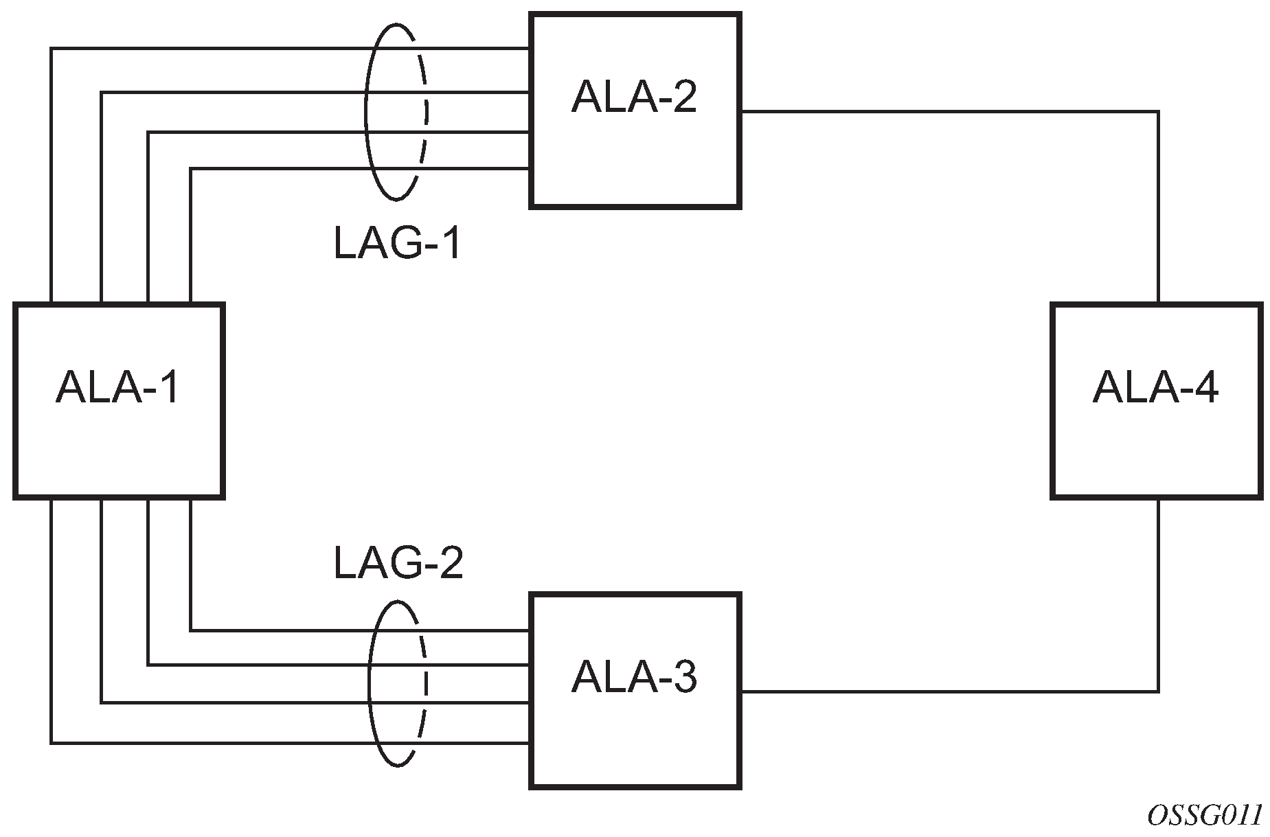
The following figure shows traffic routed between ALA-1 and ALA-2 as a LAG consisting of four ports.
LAG on access
Link Aggregation Groups (LAG) is supported on access ports and access-uplink ports. This is treated the same as LAG on network ports which provides a standard method to aggregate Ethernet links. The difference lies in how QoS is handled.
LAG and QoS policies on 7210 SAS-T, 7210 SAS-Sx/S 1/10GE, and 7210 SAS-Sx 10/100GE
In the 7210 SAS-T, 7210 SAS-Sx/S 1/10GE, and 7210 SAS-Sx 10/100GE an ingress QoS policy is applied to the aggregate traffic that is received on all the member ports of the LAG. For example, if an ingress policy is configured with a policer of PIR 100 Mbps, for a SAP configured on a LAG with two ports, then the policer limits the traffic received through the two ports to a maximum of 100 Mbps.
In the 7210 SAS-T, 7210 SAS-Sx/S 1/10GE, and 7210 SAS-Sx 10/100GE an egress QoS policy parameters are applied to all the ports that are members of the LAG (all ports get the full SLA). For example, if an egress policy is configured with a queue shaper rate of PIR 100 Mbps, and applied to an access-uplink or access LAG configured with two port members, then each port would send out 100 Mbps of traffic for a total of 200 Mbps of traffic out of the LAG. The advantage of this method over a scheme where the PIR is divided equally among all the member ports of the LAG is that, a single flow can use the entire SLA. The disadvantage is that, the overall SLA can be exceeded if the flows span multiple ports.
LAG and QoS policies on 7210 SAS-Mxp
In 7210 SAS-Mxp, a SAP ingress QoS policy or network port ingress QoS policy or network IP interface ingress QoS policy is applied to the aggregate traffic that enters the traffic through all the ports of the system. For example, if an ingress policy is configured with a policer of PIR 100 Mbps, for a SAP configured on a LAG with two ports, then the policer limits the traffic entering the system through the two ports to a maximum of 100 Mbps.
In 7210 SAS-Mxp, SAP egress QoS policy shaper parameters are applied to all the ports that are members of the LAG (all ports get the full SLA). For example, if an SAP egress policy is configured with a shaper of PIR 100 Mbps, each port would get a PIR of 100 Mbps. The advantage of this method over a scheme where the PIR is divided equally among all the member ports of the LAG is that, a single flow can uses the entire SLA. The disadvantage is that the overall SLA can be exceeded if the flows span multiple ports.
In 7210 SAS-Mxp, network port egress QoS policy shaper parameters are applied to all the ports that are members of the LAG (all ports get the full SLA). For example, if an network port egress policy is configured with a shaper of PIR 100 Mbps, each port would get a PIR of 100 Mbps. The advantage of this method over a scheme where the PIR is divided equally among all the member ports of the LAG is that, a single flow can uses the entire SLA. The disadvantage is that the overall SLA can be exceeded if the flows span multiple ports.
In 7210 SAS-Mxp, when operating in port-based queuing mode, the access egress QoS policy is applied to access ports and the policy parameters are applied to all the ports that are members of the LAG (all access ports get the full SLA). For example, if an access egress policy is configured with a shaper of PIR 100 Mbps, each port gets a PIR of 100 Mbps. The advantage of this method over a scheme where the PIR is divided equally among all the member ports of the LAG is that a single flow can use the entire SLA. The disadvantage is that the overall SLA can be exceeded if the flows span multiple ports. Access egress policy override parameters configured for the primary port of the LAG are applied to all the member ports of the LAG.
LAG and QoS policies on 7210 SAS-R6 and 7210 SAS-R12
In 7210 SAS-R6 and 7210 SAS-R12, a SAP ingress QoS policy or network port ingress QoS policy or network IP interface ingress QoS policy is applied to the aggregate traffic that enters through all the ports on a IMM. If the LAG has member ports on different IMMs, then the policy is created for each IMM and is applied to the aggregate traffic that enters through all the ports on a specific IMM. For example, if an ingress policy is configured with a policer of PIR 100 Mbps, for a SAP configured on a LAG with two ports, then the policer limits the traffic entering through the two ports of the IMM to a maximum of 100 Mbps. If the LAG has two ports on 2 different IMMs, then policy is applied each IMM individually, and the policer on each IMM allows a maximum of 100 Mbps for a total of 200 Mbps.
In 7210 SAS-R6 and 7210 SAS-R12, SAP egress QoS policy shaper parameters are applied to all the ports that are members of the LAG (all ports get the full SLA), irrespective of whether they are located on a single IMM or two different IMMs. For example, if an SAP egress policy is configured with a shaper of PIR 100 Mbps, each port would get a PIR of 100 Mbps. The advantage of this method over a scheme where the PIR is divided equally among all the member ports of the LAG is that, a single flow can uses the entire SLA. The disadvantage is that the overall SLA can be exceeded if the flows span multiple ports.
In 7210 SAS-R6 and 7210 SAS-R12, network port egress QoS policy shaper parameters are applied to all the ports that are members of the LAG (all ports get the full SLA), irrespective of whether they are located on a single IMM or two different IMMs. For example, if an network port egress policy is configured with a shaper of PIR 100 Mbps, each port would get a PIR of 100 Mbps. The advantage of this method over a scheme where the PIR is divided equally among all the member ports of the LAG is that, a single flow can uses the entire SLA. The disadvantage is that the overall SLA can be exceeded if the flows span multiple ports.
In 7210 SAS-R6 and 7210 SAS-R12, when operating in port-based queuing mode, the access egress QoS policy is applied to access ports and the policy parameters are applied to all the ports that are members of the LAG (all access ports get the full SLA). For example, if an access egress policy is configured with a shaper of PIR 100 Mbps, each port gets a PIR of 100 Mbps. The advantage of this method over a scheme where the PIR is divided equally among all the member ports of the LAG is that a single flow can use the entire SLA. The disadvantage is that the overall SLA can be exceeded if the flows span multiple ports. Access egress policy override parameters configured for the primary port of the LAG are applied to all the member ports of the LAG.
Port link damping
Hold time controls enable port link damping timers that reduce the number of link transitions reported to upper layer protocols.
The 7210 SAS OS port link damping feature guards against excessive port transitions. Any initial port transition is immediately advertised to upper layer protocols, but any subsequent port transitions are not advertised to upper layer protocols until a configured timer has expired.
An ‟up” timer controls the dampening timer for link up transitions, and a ‟down” timer controls the dampening timer for link down transitions.
LACP
Generally, link aggregation is used for two purposes: provide an increase in bandwidth and provide redundancy. Both aspects are addressed by aggregating several Ethernet links in a single LAG.
Under normal operation, all non-failing links in a specific LAG will become active and traffic is load balanced across all active links. In some circumstances, however, this is not wanted. Instead, it may be wanted that only some of the links are active and the other links be kept in stand-by condition.
LACP enhancements allow active lag-member selection based on particular constrains. The mechanism is based on the IEEE 802.3ax standard so interoperability is ensured.
Active-standby LAG operation without LACP
Active/standby LAG is used to provide redundancy while keeping consistency of QOS enforcement. Some devices do not support LACP and therefore an alternative solution is required.
The active/standby decision for LAG member links is local decision driven by preconfigured selection-criteria. This decision was communicated to remote system using LACP signaling.
As an alternative, the operator can disable the signal transmitted by using the power-off option for standby-signaling in the CLI command at the LAG level at the port member level. The transmit laser is switched off for all LAG members in standby mode. On switch over (active-links failed), the laser is switched on and all LAG members become active.
This mode of operation cannot detect physical failures on the standby link, which means that the network operator cannot be certain that the standby links are capable to take over in case of active-links failure. This is an inherent limitation of this operational mode.
When LACP goes down on a standby link, a warning message announcing that LACP has expired on the corresponding member port is printed in log 99 at the other end.
The operation where standby ports are powered down is mutually exclusive with LACP and, therefore, is modeled as a separate mode of LACP operation of power-off. For this mode, the best-port selection criteria can be used. This criteria ensures that a subgroup with the best-port (the highest priority port) is always chosen to be used as the active subgroup.
It is not possible to have an active LACP in the power-off mode before the correct selection criteria is selected.
LAG subgroups
LACP is used to make a selection of active links predictable and compatible with any vendor equipment. See IEEE STD 802.3-2002, Section 3, Clause 43.6.1, which describes how LACP allows standby and active signaling.
The 7210 SAS-T, 7210 SAS-R6, 7210 SAS-R6, 7210 SAS-Mxp, 7210 SAS-Sx/S 1/10GE (operating in standalone and standalone-VC mode), and 7210 SAS-Sx 10/100GE (operating in standalone mode) implementation of LACP supports the following:
A specific LAG member can be assigned to subgroups. The selection algorithm then assures that only members of a single subgroup are selected as active links.
The selection algorithm is effective only if LACP is enabled on a specific LAG. At the same time, it is assumed that the connected system also has LACP enabled (active or passive mode).
The algorithm selects active links based on following criteria:
Depending on the selection-criteria settings either the subgroup with the highest number of eligible links or the subgroup with the highest aggregate weight of all eligible members is selected first.
If multiple groups satisfy the selection criteria, the currently active subgroup remains active. Initially, the subgroup containing the highest priority eligible link is selected.
Only links pertaining to a single subgroup are active at any time.
An eligible member refers to a LAG member link that can potentially become active; that is, it is operationally up. If the slave-to-partner flag is set, the remote system does not disable its use (by signaling the ‟Standby” bit using LACP).
The selection algorithm works in a reverting mode. Each time the configuration or status of any link in a LAG changes, the selection algorithm is rerun. In case of a tie between two groups (one of them being currently active), the active group remains active (no reverting).
LAG and ECMP hashing
See the 7210 SAS-Mxp, R6, R12, S, Sx, T Router Configuration Guide for more information about ECMP support for 7210 SAS platforms.
When a requirement exists to increase the available bandwidth for a logical link that exceeds the physical bandwidth or add redundancy for a physical link, typically one of the methods is applied; equal cost multi-path (ECMP) or LAG. A 7210 SAS can deploy both at the same time, meaning, using ECMP of two or more LAGs or single links.The Nokia implementation supports per flow hashing used to achieve uniform loadspreading and per service hashing designed to provide consistent per service forwarding. Depending on the type of traffic that needs to be distributed into an ECMP or a LAG, different variables are used as input to the hashing algorithm.
An option is provided per LAG to select the hashing function to be used for load-balancing flows on the member ports of the LAG. Users can use one of the available options based on the flows they have in their network and select an option that helps improve the load-balancing of flows in their network. The packets fields selected by the hashing function is different for some flows with the two hashing functions and is provided in the following tables.
LAG hashing for the 7210 SAS-T (network mode)
The following table describes the packet fields used for hashing for services configured on the 7210 SAS-T in network mode.
The following notes apply to LAG hashing algorithm for services and traffic flows configured on the 7210 SAS-T configured in the network operating mode.
In the case of LSR, incoming labels are used for hashing.
The term ‟learned” corresponds to destination MAC.
The term ‟source and destination MAC” refers to customer source and destination MACs unless otherwise specified.
Traffic type |
Hashing options |
Packet fields used |
||||||||||||
|---|---|---|---|---|---|---|---|---|---|---|---|---|---|---|
|
Hash-1 |
Hash-2 |
BDA |
BSA |
CDA |
CSA |
EtherType |
Ingress Port-ID |
ISID |
MPLS label stack |
Source and destination |
VLAN |
|||
|
MAC |
IP |
L4 ports |
||||||||||||
VPLS service SAP to SAP |
||||||||||||||
IP traffic (learned) |
✓ |
✓ |
✓ |
|||||||||||
✓ |
✓ |
✓ |
✓ |
|||||||||||
IP traffic (unlearned) |
✓ |
✓ |
✓ |
✓ |
||||||||||
✓ |
✓ |
✓ |
✓ |
|||||||||||
PBB traffic (learned) |
✓ |
✓ |
✓ |
✓ |
||||||||||
✓ |
✓ |
✓ |
✓ |
✓ |
||||||||||
PBB traffic (unlearned) |
✓ |
✓ |
✓ |
✓ |
✓ |
|||||||||
✓ |
✓ |
✓ | ✓ |
✓ |
||||||||||
MPLS traffic (learned) |
✓ |
✓1 |
✓ |
|||||||||||
✓ |
✓ |
✓2 |
✓ |
|||||||||||
MPLS traffic (unlearned) |
✓ |
✓ |
✓2 |
✓ |
||||||||||
✓ |
✓ |
✓2 |
✓ |
|||||||||||
Non-IP traffic (learned) |
✓ |
✓ |
✓ |
✓ |
||||||||||
✓ |
✓ |
✓ | ✓ | ✓ |
||||||||||
Non-IP traffic (unlearned) |
✓ |
✓ |
✓ |
✓ |
✓ |
|||||||||
✓ |
✓ |
✓ |
✓ |
✓ |
||||||||||
VPLS service SAP to SDP |
||||||||||||||
IP traffic (learned) |
✓ |
✓ |
✓ |
|||||||||||
✓ |
✓ |
✓ |
✓ |
|||||||||||
IP traffic (unlearned) |
✓ |
✓ |
✓ |
✓ |
||||||||||
✓ |
✓ | ✓ |
✓ |
|||||||||||
PBB traffic (learned) |
✓ |
✓ |
✓ |
✓ |
||||||||||
✓ |
✓ |
✓ |
✓ |
✓ |
||||||||||
PBB traffic (unlearned) |
✓ |
✓ |
✓ |
✓ |
✓ |
|||||||||
✓ |
✓ |
✓ |
✓ |
✓ |
||||||||||
MPLS traffic (learned) |
✓ |
✓ |
✓ |
|||||||||||
✓ |
✓ |
✓2 |
✓ |
|||||||||||
MPLS traffic (unlearned) |
✓ |
✓ |
✓2 |
✓ |
||||||||||
✓ |
✓ |
✓2 |
✓ |
|||||||||||
Non-IP traffic (learned) |
✓ |
✓ |
✓ |
✓ |
||||||||||
✓ |
✓ |
✓ |
✓ |
✓ |
||||||||||
Non-IP traffic (unlearned) |
✓ |
✓ |
✓ |
✓ |
✓ |
|||||||||
✓ |
✓ |
✓ |
✓ |
✓ |
||||||||||
VPLS service SDP to SAP |
||||||||||||||
IP traffic (learned) |
✓ |
✓3 |
✓ |
✓ |
||||||||||
— |
||||||||||||||
PBB traffic (learned) |
✓ |
✓3 |
||||||||||||
— |
||||||||||||||
Non-IP traffic (learned) |
✓ |
✓ |
✓3 |
|||||||||||
— |
||||||||||||||
All traffic (learned) |
— |
|||||||||||||
✓ |
✓ |
✓3 |
||||||||||||
All traffic (unlearned) |
✓ |
✓ |
✓3 |
|||||||||||
✓ |
✓ |
✓3 |
||||||||||||
VPLS service SDP to SDP |
||||||||||||||
All traffic (learned) |
✓ |
✓ 3 |
||||||||||||
✓ |
✓ |
✓3 |
||||||||||||
All traffic (unlearned) |
✓ |
✓ |
✓3 |
|||||||||||
✓ |
✓ |
✓3 |
||||||||||||
Epipe service SAP to SAP |
||||||||||||||
IP traffic |
✓ |
✓ |
✓ |
|||||||||||
✓ |
✓ |
✓ |
✓ |
|||||||||||
PBB traffic |
✓ |
✓ |
✓ |
✓ |
||||||||||
✓ |
✓ |
✓ |
✓ |
✓ |
||||||||||
MPLS traffic |
✓ |
✓1 |
✓ |
|||||||||||
✓ |
✓ |
✓2 |
✓ |
|||||||||||
Non-IP traffic |
✓ |
✓ |
✓ |
✓ |
||||||||||
✓ |
✓ |
✓ |
✓ |
✓ |
||||||||||
Epipe service SAP to SDP |
||||||||||||||
IP traffic |
✓ |
✓ |
✓ |
|||||||||||
✓ |
✓ |
✓ |
✓ |
|||||||||||
PBB traffic |
✓ |
✓ |
✓ |
✓ |
||||||||||
✓ |
✓ |
✓ |
✓ |
✓ |
||||||||||
MPLS traffic |
✓ |
✓ |
✓ |
|||||||||||
✓ |
✓ |
✓2 |
✓ |
|||||||||||
Non-IP traffic |
✓ |
✓ |
✓ |
✓ |
||||||||||
✓ |
✓ |
✓ |
✓ |
✓ |
||||||||||
Epipe service SDP to SAP |
||||||||||||||
IP traffic |
✓ |
✓3 |
✓ |
✓ |
||||||||||
— |
||||||||||||||
PBB traffic |
✓ |
✓3 |
||||||||||||
— |
||||||||||||||
Non-IP traffic |
✓ |
✓ |
✓3 |
|||||||||||
— |
||||||||||||||
All traffic |
— |
|||||||||||||
✓ |
✓ |
✓3 |
||||||||||||
MPLS – LSR |
||||||||||||||
All traffic |
✓ |
✓1 |
||||||||||||
✓ |
✓ |
✓2 |
✓4 |
|||||||||||
PBB VPLS service B-SAP to B-SAP (PBB BCB traffic) |
||||||||||||||
IP traffic (learned) |
✓ |
✓ |
✓ |
|||||||||||
✓ |
✓ |
✓ |
✓ |
|||||||||||
IP traffic (unlearned) |
✓ |
✓ |
✓ |
✓ |
||||||||||
✓ |
✓ |
✓ |
✓ |
|||||||||||
L2 and non-IP traffic (learned) |
✓ |
✓ |
✓ |
|||||||||||
✓ |
✓ |
✓ |
✓ |
✓ |
||||||||||
L2 and non-IP traffic (unlearned) |
✓ |
✓ |
✓ |
✓ |
✓ |
|||||||||
✓ |
✓ |
✓ |
✓ |
✓ |
||||||||||
PBB VPLS service I-SAP to B-SAP (originating PBB BEB traffic) |
||||||||||||||
IP traffic (learned) |
✓ |
✓ |
✓ |
|||||||||||
✓ |
✓ |
✓ |
✓ |
|||||||||||
IP traffic (unlearned) |
✓ |
✓ |
✓ |
✓ |
||||||||||
✓ |
✓ |
✓ |
✓ |
|||||||||||
L2 and non-IP traffic (learned) |
✓ |
✓ |
✓ |
✓ |
✓ |
|||||||||
✓ |
✓ |
✓ |
✓ |
✓ |
✓ |
|||||||||
L2 and non-IP traffic (unlearned) |
✓ |
✓ |
✓ |
✓ |
✓ |
✓ |
||||||||
✓ |
✓ |
✓ |
✓ |
✓ |
✓ |
|||||||||
PBB VPLS service B-SAP to I-SAP (terminating PBB BEB traffic) |
||||||||||||||
IP traffic (learned) |
✓ |
✓ |
✓ |
|||||||||||
✓ |
✓ |
✓ |
✓ |
|||||||||||
IP traffic (unlearned) |
✓ |
✓ |
✓ |
✓ |
||||||||||
✓ |
✓ |
✓ |
✓ |
|||||||||||
L2 and non-IP traffic (learned) |
✓ |
✓ |
✓ |
✓ |
||||||||||
✓ |
✓ |
✓ |
✓ |
✓ |
||||||||||
L2 and non-IP traffic (unlearned) |
✓ |
✓ |
✓ |
✓ |
✓ |
|||||||||
✓ |
✓ |
✓ |
✓ |
✓ |
||||||||||
PBB Epipe service PBB Epipe I-SAP to B-SAP (originating PBB BEB traffic) |
||||||||||||||
IP traffic |
✓ |
✓ |
✓ |
✓ |
||||||||||
✓ |
✓ |
✓ |
✓ |
|||||||||||
L2 and non-IP traffic |
✓ |
✓ |
✓ |
✓ |
✓ |
✓ |
||||||||
✓ |
✓ |
✓ |
✓ |
✓ |
✓ |
|||||||||
PBB Epipe service PBB Epipe SAP to B-SAP (terminating PBB BEB traffic) |
||||||||||||||
IP traffic |
✓ |
✓ |
✓ |
|||||||||||
✓ |
✓ |
✓ |
||||||||||||
L2 and non-IP traffic |
✓ |
✓ |
✓ |
✓ |
||||||||||
✓ |
✓ |
✓ |
✓ |
|||||||||||
VPRN service SAP to SAP SAP to SDP SDP to SAP |
||||||||||||||
— |
✓ |
✓ |
✓ |
|||||||||||
✓ |
✓ |
✓ |
✓ |
|||||||||||
IES service (IPv4) IES SAP to IES SAP |
||||||||||||||
— |
✓ |
✓ |
✓ |
|||||||||||
✓ |
✓ |
✓ |
✓ |
|||||||||||
IES service (IPv4) IES SAP to IPv4 network port interface |
||||||||||||||
— |
✓ |
✓ |
✓ |
|||||||||||
✓ |
✓ |
✓ |
✓ |
|||||||||||
Network port IPv4 interface IPv4 network interface to IPv4 network interface |
||||||||||||||
— |
✓ |
✓ |
✓ |
|||||||||||
✓ |
✓ |
✓ |
✓ |
|||||||||||
Network port IPv6 interface IPv6 network interface to IPv6 network interface |
||||||||||||||
— |
✓ |
✓5 |
✓ |
|||||||||||
✓ |
✓ |
✓5 |
✓ |
|||||||||||
LAG hashing for the 7210 SAS-T (access-uplink mode)
The following table describes the packet fields used for hashing for services configured on the 7210 SAS-T in access-uplink mode.
The following notes apply to LAG hashing algorithm for services configured on the 7210 SAS-T in the access-uplink operating mode:
The term ‟Learned” corresponds to destination MAC.
Source/destination MAC refers to customer source/destination MACs unless otherwise specified.
VLAN ID is considered for Learned - PBB, MPLS, Non-IP traffic in VPLS service only for traffic ingressing at dot1q, Q.*, Q1.Q2 SAPs.
Only outer VLAN tag is used for hashing.
Traffic type |
Packet fields used |
|||||||||
|---|---|---|---|---|---|---|---|---|---|---|
|
BDA |
BSA |
EtherType |
Ingress Port-ID |
ISID |
MPLS Label Stack |
Source and destination |
VLAN |
|||
|
MAC |
IP |
L4 Ports |
||||||||
VPLS service SAP to SAP |
||||||||||
IP traffic (learned) |
✓ |
✓ |
||||||||
IP traffic (unlearned) |
✓ |
✓ |
✓ |
|||||||
PBB traffic (learned) |
✓ |
✓ |
||||||||
PBB traffic (unlearned) |
✓ |
✓ |
✓ |
✓ |
||||||
MPLS traffic (learned) |
✓6 |
|||||||||
IP MPLS traffic (unlearned) |
✓ |
✓7 |
✓ |
|||||||
L2 MPLS traffic (unlearned) |
✓ |
✓7 |
||||||||
Non-IP traffic (learned) |
✓ |
✓ |
✓ |
|||||||
Non-IP traffic (unlearned) |
✓ |
✓ |
✓ |
✓ |
||||||
Epipe service SAP to SAP |
||||||||||
IP traffic |
✓ |
✓ |
✓ |
|||||||
PBB traffic |
✓ |
✓ |
✓ |
✓ |
||||||
IP MPLS traffic |
✓ |
✓7 |
✓ |
|||||||
L2 MPLS traffic |
✓ |
✓7 |
||||||||
Non-IP traffic |
✓ |
✓ |
✓ |
✓ |
||||||
IES service (IPv4) IES SAP to IES SAP |
||||||||||
IPv4 unicast traffic |
✓ |
✓ |
||||||||
LAG hashing for the 7210 SAS-R6 and 7210 SAS-R12
The following table describes the packet fields used for hashing for services configured on the 7210 SAS-R6 and 7210 SAS-R12.
The following notes apply to LAG hashing algorithm for services and traffic flows configured on the 7210 SAS-R6 and 7210 SAS-R12:
The term ‟service_id” refers to the service ID of the egressing VPLS, Epipe, IES, or VPRN service.
The term ‟lag_index” refers to the Lag-IfIndex of the egressing lag.
the terms ‟encap_value” and ‟service_vlan” are based on the inner and outer VLAN values of the egressing LAG SAP.
The term ‟sap_index” is a value assigned uniquely for each SAP internally.
Parameters used for LAG hashing are the same in both SAP egress queue mode (SAP-based egress scheduling) or port egress queue mode (port-based egress scheduling), unless otherwise specified.
The term ‟learned” corresponds to the destination MAC.
The term ‟source and destination MAC” refers to customer source and destination MACs, unless otherwise specified.
In the case of a LAG with two ports at egress, different ingress port IDs may result in the same hash index, which causes traffic to always get hashed to only one of the ports. Load balancing is expected to occur when there are more than 2 ports in the lag.
The term ‟mgid” is the multicast group ID and is a software-allocated number. A unique number is allocated for each Layer-2 multicast MAC address.
The 7210 SAS supports Layer-2 multicast in a VPLS service. A group of 32 multicast IP addresses map to a single Layer-2 multicast MAC address. The ‟mgid” parameter remains the same for all IP multicast addresses that map to the same Layer-2 multicast MAC address.
Traffic type |
Hashing options |
Packet fields used |
|||||||||||
|---|---|---|---|---|---|---|---|---|---|---|---|---|---|
|
Hash-1 Version 1 |
Hash-1 Version 2 |
Hash-2 |
BDA |
BSA |
EtherType |
Ingress Port-ID |
ISID |
MPLS Label Stack |
Source and destination |
VLAN |
|||
|
MAC |
IP |
L4 Ports |
|||||||||||
VPLS service SAP to SAP |
|||||||||||||
IP traffic (learned) |
✓ |
✓ |
✓ |
||||||||||
✓ |
✓ |
✓ |
|||||||||||
✓ |
✓ |
✓ |
✓ |
||||||||||
PBB traffic (learned) |
✓ |
✓ |
✓ |
✓ |
|||||||||
✓ |
✓ |
✓ |
✓ |
||||||||||
✓ |
✓ |
✓ |
✓ |
✓ |
|||||||||
MPLS traffic (learned) |
✓ |
✓8 |
✓ |
||||||||||
✓ |
✓8 |
✓ |
|||||||||||
✓ |
✓ |
✓9 |
|||||||||||
Non-IP traffic (learned) |
✓ |
✓ |
✓ |
✓ |
|||||||||
✓ |
✓ |
✓ |
✓ |
||||||||||
✓ |
✓ |
✓ |
✓ |
✓ |
|||||||||
All traffic (unlearned) |
See note10 |
|
|
|
|
|
|
|
|
|
|
||
|
|
|
|
|
|
|
|
|
|
||||
|
|
|
|
|
|
|
|
|
|
||||
VPLS service SAP to SDP |
|||||||||||||
IP traffic (learned) |
✓ |
✓ |
✓ |
||||||||||
✓ |
✓ |
✓ |
|||||||||||
✓ |
✓ |
✓ |
✓ |
||||||||||
IP traffic (unlearned) |
✓ |
✓ |
✓ |
✓ |
|||||||||
✓ |
✓ |
✓ |
✓ |
||||||||||
✓ |
✓ |
✓ |
✓ |
||||||||||
PBB traffic (learned) |
✓ |
✓ |
✓ |
✓ |
|||||||||
✓ |
✓ |
✓ |
✓ |
||||||||||
✓ |
✓ |
✓ |
✓ |
✓ |
|||||||||
PBB traffic (unlearned) |
✓ |
✓ |
✓ |
✓ |
✓ |
||||||||
✓ |
✓ |
✓ |
✓ |
✓ |
|||||||||
✓ |
✓ |
✓ |
✓ |
✓ |
|||||||||
MPLS traffic (learned) |
✓ |
✓ |
✓ |
||||||||||
✓ |
✓ |
✓ |
|||||||||||
✓ |
✓ |
✓9 |
✓11 |
||||||||||
MPLS traffic (unlearned) |
✓ |
✓ |
✓9 |
✓11 |
|||||||||
✓ |
✓ |
✓9 |
✓11 |
||||||||||
✓ |
✓ |
✓9 |
✓11 |
||||||||||
Non-IP traffic (learned) |
✓ |
✓ |
✓ |
✓ |
|||||||||
✓ |
✓ |
✓ |
✓ |
||||||||||
✓ |
✓ |
✓ |
✓ |
✓ |
|||||||||
Non-IP traffic (unlearned) |
✓ |
✓ |
✓ |
✓ |
✓ |
||||||||
— |
|||||||||||||
✓ |
✓ |
✓ |
✓ |
✓ |
|||||||||
VPLS service SDP to SAP |
|||||||||||||
IP traffic (learned) |
✓ |
✓9 |
✓ |
✓ |
✓ |
||||||||
✓ |
✓ |
✓ |
|||||||||||
— |
|||||||||||||
All traffic, excluding IP traffic (learned) |
✓ |
✓ |
✓12 |
||||||||||
✓ |
✓ |
✓12 |
|||||||||||
— |
|||||||||||||
All traffic (learned) |
— |
||||||||||||
— |
|||||||||||||
✓ |
✓ |
✓12 |
|||||||||||
All traffic (unlearned) |
See note10 |
|
|
|
|
|
|
|
|
|
|
||
|
|
|
|
|
|
|
|
|
|
||||
VPLS service SDP to SDP |
|||||||||||||
All traffic (learned) |
✓ |
✓12 |
|||||||||||
✓ |
✓12 |
||||||||||||
✓ |
✓ |
✓12 |
|||||||||||
All traffic (unlearned) |
✓ |
✓ |
✓12 |
||||||||||
✓ |
✓ |
✓12 |
|||||||||||
✓ |
✓ |
✓12 |
|||||||||||
Epipe service SAP to SAP |
|||||||||||||
IP traffic |
✓ |
✓ |
✓ |
||||||||||
✓ |
✓ |
✓ |
|||||||||||
✓ |
✓ |
✓ |
✓ |
||||||||||
PBB traffic |
✓ |
✓ |
✓ |
✓ |
|||||||||
✓ |
✓ |
✓ |
✓ |
||||||||||
✓ |
✓ |
✓ |
✓ |
✓ |
|||||||||
MPLS traffic |
✓ |
✓8 |
✓ |
||||||||||
✓ |
✓8 |
✓ |
|||||||||||
✓ |
✓ |
✓9 |
|||||||||||
Non-IP traffic |
✓ |
✓ |
✓ |
✓ |
|||||||||
✓ |
✓ |
✓ |
✓ |
||||||||||
✓ |
✓ |
✓ |
✓ |
✓ |
|||||||||
Epipe service SAP to SDP |
|||||||||||||
IP traffic |
✓ |
✓ |
✓ |
||||||||||
✓ |
✓ |
✓ |
|||||||||||
✓ |
✓ |
✓ |
✓ |
||||||||||
PBB traffic |
✓ |
✓ |
✓ |
✓ |
|||||||||
✓ |
✓ |
✓ |
✓ |
||||||||||
✓ |
✓ |
✓ |
✓ |
✓ |
|||||||||
MPLS traffic |
✓ |
✓ |
✓ |
||||||||||
✓ |
✓ |
✓ |
|||||||||||
✓ |
✓ |
✓9 |
✓11 |
||||||||||
Non-IP traffic |
✓ |
✓ |
✓ |
✓ |
|||||||||
✓ |
✓ |
✓ |
✓ |
||||||||||
✓ |
✓ |
✓ |
✓ |
✓ |
|||||||||
Epipe service SDP to SAP |
|||||||||||||
IP traffic |
✓ |
✓ 9 |
✓ |
✓ |
✓ |
||||||||
✓ |
✓ |
✓ |
|||||||||||
— |
|||||||||||||
All other traffic |
✓ |
✓ |
✓12 |
||||||||||
✓ |
✓ |
✓12 |
|||||||||||
— |
|||||||||||||
All traffic |
— |
||||||||||||
— |
|||||||||||||
✓ |
✓ |
✓12 |
|||||||||||
MPLS – LSR |
|||||||||||||
All traffic |
✓ |
✓8 |
|||||||||||
✓ |
✓8 |
||||||||||||
✓ |
✓ |
✓13 |
✓14 |
||||||||||
VPLS (Multicast traffic with IGMP snooping enabled) SAP to SAP SDP to SAP |
|||||||||||||
— |
See note 15 |
|
|
|
|
|
|
|
|
|
|
||
|
|
|
|
|
|
|
|
|
|
||||
|
|
|
|
|
|
|
|
|
|
||||
VPRN service SAP to SAP SAP to SDP SDP to SAP |
|||||||||||||
— |
✓ |
✓ |
✓ |
||||||||||
✓ |
✓ |
✓ |
|||||||||||
✓ |
✓ |
✓ |
✓ |
||||||||||
IES service (IPv4) IES SAP to IES SAP |
|||||||||||||
— |
✓ |
✓ |
✓ |
||||||||||
✓ |
✓ |
✓ |
|||||||||||
✓ |
✓ |
✓ |
✓ |
||||||||||
IES service (IPv4) IES SAP to IPv4 network port interface |
|||||||||||||
— |
✓ |
✓ |
✓ |
||||||||||
✓ |
✓ |
✓ |
|||||||||||
✓ |
✓ |
✓ |
✓ |
||||||||||
Network port IPv4 interface IPv4 network interface to IPv4 network interface |
|||||||||||||
— |
✓ |
✓ |
✓ |
||||||||||
✓ |
✓ |
✓ |
|||||||||||
✓ |
✓ |
✓ |
✓ |
||||||||||
Network port IPv6 interface IPv6 network interface to IPv6 network interface |
|||||||||||||
— |
✓ |
✓16 |
✓ |
||||||||||
✓ |
✓16 |
✓ |
|||||||||||
✓ |
✓ |
✓16 |
✓ |
||||||||||
LAG hashing for the 7210 SAS-Mxp
The following table describes the packet fields used for hashing for services configured on the 7210 SAS-Mxp.
The following notes apply to LAG hashing algorithm for services and traffic flows configured on the 7210 SAS-Mxp :
In the case of LSR, incoming labels are used for hashing.
The term ‟learned” corresponds to the destination MAC.
The term ‟source and destination MAC” refers to customer source and destination MACs unless otherwise specified.
The term ‟service_id” refers to the service ID of the egressing VPLS, Epipe, IES, or VPRN service.
The term ‟lag_index” refers to the Lag-IfIndex of the egressing lag.
The terms ‟encap_value” and ‟service_vlan” are based on the inner/outer VLAN values of the egressing LAG SAP.
The term ‟sap_index” is a value assigned uniquely for each SAP internally.
Parameters used for LAG hashing are the same in both SAP egress queue mode (SAP-based egress scheduling) or port egress queue mode (port-based egress scheduling mode), unless otherwise specified previously.
The term ‟mgid” is the multicast group ID and is a software-allocated number. A unique number is allocated for each Layer-2 multicast MAC address.
The 7210 SAS supports Layer-2 multicast in a VPLS service. A group of 32 multicast IP addresses map to a single Layer-2 multicast MAC address. The ‟mgid” parameter remains the same for all IP multicast addresses that map to the same Layer-2 multicast MAC address.
|
Traffic type |
Hashing options |
Packet fields used |
|||||||||||
|---|---|---|---|---|---|---|---|---|---|---|---|---|---|
|
Hash-1 Version 1 |
Hash-1 Version 2 |
Hash-2 |
BDA |
BSA |
EtherType |
Ingress Port-ID |
ISID |
MPLS Label Stack |
Source and destination |
VLAN |
|||
|
MAC |
IP |
L4 Ports |
|||||||||||
|
VPLS and Epipe services SAP to SAP |
|||||||||||||
|
IP traffic (VPLS learned and Epipe; port-based egress scheduling) |
✓ |
✓ |
✓ |
||||||||||
|
✓ |
✓ |
✓ |
|||||||||||
|
✓ |
✓ |
✓ |
✓ |
||||||||||
|
MPLS traffic (VPLS learned and Epipe; port-based egress scheduling) |
✓ |
✓ |
✓ |
||||||||||
|
✓ |
✓ |
✓ |
|||||||||||
|
✓ |
✓ |
✓17 |
|||||||||||
|
Non-IP traffic (VPLS learned and Epipe; port-based egress scheduling) |
✓ |
✓ |
✓ |
✓ |
|||||||||
|
✓ |
✓ |
✓ |
✓ |
||||||||||
|
✓ |
✓ |
✓ |
✓ |
✓ |
|||||||||
|
All traffic (learned and unlearned; SAP-based egress scheduling) |
See note18 |
|
|
|
|
|
|
||||||
|
|
|
|
|
|
|
|
|
|
|
||||
|
|
|
|
|
|
|
|
|
|
|
||||
|
All traffic (VPLS unlearned; port-based egress scheduling) |
See note18 |
|
|
|
|
|
|
|
|
|
|
||
|
|
|
|
|
|
|
|
|
|
|
||||
|
|
|
|
|
|
|
|
|
|
|
||||
|
VPLS service SAP to SDP |
|||||||||||||
|
IP traffic (learned; SAP-based and port-based egress sheduling) |
✓ |
✓ |
✓ |
||||||||||
|
✓ |
✓ |
✓ |
|||||||||||
|
✓ |
✓ |
✓ |
✓ |
||||||||||
|
IP traffic (unlearned; SAP-based and port-based egress sheduling) |
✓ |
✓ |
✓ |
✓ |
|||||||||
|
✓ |
✓ |
✓ |
✓ |
||||||||||
|
✓ |
✓ |
✓ |
✓ |
||||||||||
|
MPLS traffic (learned; SAP-based and port-based egress sheduling) |
✓ |
✓ |
✓ |
||||||||||
|
✓ |
✓ |
✓ |
|||||||||||
|
✓ |
✓ |
✓17 |
|||||||||||
|
MPLS traffic (unlearned; SAP-based and port-based egress sheduling) |
✓ |
✓ |
✓17 |
||||||||||
|
✓ |
✓ |
✓17 |
|||||||||||
|
✓ |
✓ |
✓17 |
|||||||||||
|
Non-IP traffic (learned; SAP-based and port-based egress sheduling) |
✓ |
✓ |
✓ |
✓ |
|||||||||
|
✓ |
✓ |
✓ |
✓ |
||||||||||
|
✓ |
✓ |
✓ |
✓ |
✓ |
|||||||||
|
Non-IP traffic (unlearned; SAP-based and port-based egress sheduling) |
✓ |
✓ |
✓ |
✓ |
✓ |
||||||||
|
✓ |
✓ |
✓ |
✓ |
✓ |
|||||||||
|
✓ |
✓ |
✓ |
✓ |
✓ |
|||||||||
|
Epipe service SAP to SDP |
|||||||||||||
|
IP traffic (SAP-based and port-based egress sheduling) |
✓ |
✓ |
✓ |
||||||||||
|
✓ |
✓ |
✓ |
|||||||||||
|
✓ |
✓ |
✓ |
✓ |
||||||||||
|
MPLS traffic (SAP-based and port-based egress sheduling) |
✓ |
✓ |
✓ |
||||||||||
|
✓ |
✓ |
✓ |
|||||||||||
|
✓ |
✓ |
✓ 17 |
|||||||||||
|
Non-IP traffic (SAP-based and port-based egress sheduling) |
✓ |
✓ |
✓ |
✓ |
|||||||||
|
✓ |
✓ |
✓ |
✓ |
||||||||||
|
✓ |
✓ |
✓ |
✓ |
✓ |
|||||||||
|
VPLS and Epipe services SDP to SAP |
|||||||||||||
|
All traffic (including VPLS learned and unlearned; SAP-based egress scheduling) |
See note18 |
|
|
|
|
|
|
|
|
|
|
||
|
|
|
|
|
|
|
|
|
|
|
||||
|
|
|
|
|
|
|
|
|
|
|
||||
|
All traffic (VPLS unlearned; port-based egress scheduling) |
See note18 |
|
|
|
|
|
|
|
|
|
|
||
|
|
|
|
|
|
|
|
|
|
|
||||
|
|
|
|
|
|
|
|
|
|
|
||||
|
All other traffic (VPLS learned and Epipe; port-based egress scheduling) |
✓ |
✓19 |
|||||||||||
|
✓ |
✓ |
✓ |
|||||||||||
|
✓ |
✓ |
✓19 |
|||||||||||
|
VPLS service SDP to SDP |
|||||||||||||
|
All traffic (learned; SAP-based and port-based egress sheduling) |
✓ |
✓19 |
|||||||||||
|
✓ |
✓19 |
||||||||||||
|
✓ |
✓ |
✓19 |
|||||||||||
|
All traffic (unlearned; SAP-based and port-based egress sheduling) |
✓ |
✓ |
✓19 |
||||||||||
|
✓ |
✓ |
✓19 |
|||||||||||
|
✓ |
✓ |
✓19 |
|||||||||||
|
MPLS – LSR |
|||||||||||||
|
All traffic (SAP-based and port-based egress sheduling) |
✓ |
✓19 |
|||||||||||
|
✓ |
✓19 |
||||||||||||
|
✓ |
✓ |
✓20 |
✓21 |
||||||||||
|
VPLS (Multicast traffic with IGMP snooping enabled) SAP to SAP SDP to SAP |
|||||||||||||
|
— (SAP-based and port-based egress sheduling) |
See note 22 |
|
|
|
|
|
|
|
|
|
|
||
|
|
|
|
|
|
|
|
|
|
|
||||
|
|
|
|
|
|
|
|
|
|
|
||||
|
VPRN service SAP to SAP SDP to SAP |
|||||||||||||
|
All traffic (SAP-based egress scheduling) |
See note18 |
|
|
|
|
|
|
|
|
|
|
||
|
|
|
|
|
|
|
|
|
|
|
||||
|
|
|
|
|
|
|
|
|
|
|
||||
|
All traffic (Port-based egress scheduling) |
✓ |
✓ |
✓ |
||||||||||
|
✓ |
✓ |
✓ |
|||||||||||
|
✓ |
✓ |
✓ |
✓ |
||||||||||
|
VPRN service SAP to SDP |
|||||||||||||
|
All traffic (SAP-based and port-based egress sheduling) |
✓ |
✓ |
✓ |
||||||||||
|
✓ |
✓ |
✓ |
|||||||||||
|
✓ |
✓ |
✓ |
✓ |
||||||||||
|
IES service (IPv4) IES SAP to IES SAP |
|||||||||||||
|
All traffic (SAP-based egress scheduling) |
See note18 |
|
|
|
|
|
|
|
|
|
|
||
|
|
|
|
|
|
|
|
|
|
|
||||
|
|
|
|
|
|
|
|
|
|
|
||||
|
All traffic (Port-based egress scheduling) |
✓ |
✓ |
✓ |
||||||||||
|
✓ |
✓ |
✓ |
|||||||||||
|
✓ |
✓ |
✓ |
✓ |
||||||||||
|
IES service (IPv4) IES SAP to IPv4 network port interface |
|||||||||||||
|
— (SAP-based and port-based egress sheduling) |
✓ |
✓ |
✓ |
||||||||||
|
✓ |
✓ |
✓ |
|||||||||||
|
✓ |
✓ |
✓ |
✓ |
||||||||||
|
Network port IPv4 interface IPv4 network interface to IPv4 network interface |
|||||||||||||
|
— (SAP-based and port-based egress sheduling) |
✓ |
✓ |
✓ |
||||||||||
|
✓ |
✓ |
✓ |
|||||||||||
|
✓ |
✓ |
✓ |
✓ |
||||||||||
|
Network port IPv6 interface IPv6 network interface to IPv6 network interface |
|||||||||||||
|
— (SAP-based and port-based egress sheduling) |
✓ |
✓ |
✓ |
||||||||||
|
✓ |
✓ |
✓ |
|||||||||||
|
✓ |
✓ |
✓ |
✓ |
||||||||||
LAG hashing algorithm for the 7210 SAS-Sx/S 1/10GE and 7210 SAS-Sx 10/100GE in standalone and standalone-VC mode
The following table describes the packet fields used for hashing for services configured on the 7210 SAS-Sx/S 1/10GE and 7210 SAS-Sx 10/100GE operating in the standalone and standalone-VC modes.
The following terms are use in LAG hashing algorithm for services and traffic flows configured on the 7210 SAS-Sx/S 1/10GE and 7210 SAS-Sx 10/100GE in standalone and standalone-VC Mode:
The term ‟learned” corresponds to the destination MAC.
The term ‟source and destination MAC” refers to the customer source and destination MACs unless otherwise specified.
Traffic type |
Hashing options |
Packet fields used |
|||||||||||
|---|---|---|---|---|---|---|---|---|---|---|---|---|---|
|
Hash-1 Version 1 |
Hash-1 Version 2 |
Hash-2 |
BDA |
BSA |
EtherType |
Ingress Port-ID |
ISID |
MPLS Label Stack |
Source and destination |
VLAN |
|||
|
MAC |
IP |
L4 Ports |
|||||||||||
VPLS service SAP to SAP |
|||||||||||||
IP traffic (learned) |
✓ |
✓ |
✓ |
||||||||||
✓ |
✓ |
✓ |
|||||||||||
✓ |
✓ |
✓ |
✓ |
||||||||||
IP traffic (unlearned) |
✓ |
✓ |
✓ |
✓ |
|||||||||
✓ |
✓ |
✓ |
✓ |
||||||||||
✓ |
✓ |
✓ |
✓ |
||||||||||
PBB traffic (learned) |
✓ |
✓ |
✓ |
✓ |
✓ |
||||||||
✓ |
✓ |
✓ |
✓ |
✓ |
|||||||||
✓ |
✓ |
✓ |
✓ |
✓ |
✓ |
||||||||
PBB traffic (unlearned) |
✓ |
✓ |
✓ |
✓ |
✓ |
✓ |
|||||||
✓ |
✓ |
✓ |
✓ |
✓ |
✓ |
||||||||
✓ |
✓ |
✓ |
✓ |
✓ |
✓ |
||||||||
MPLS traffic (learned) |
✓ |
✓ |
✓23 |
✓ |
|||||||||
✓ |
✓ |
✓23 |
✓ |
||||||||||
✓ |
✓ |
✓24 |
✓25 |
||||||||||
MPLS traffic (unlearned) |
✓ |
✓ |
✓24 |
✓25 |
|||||||||
✓ |
✓ |
✓24 |
✓25 |
||||||||||
✓ |
✓ |
✓24 |
✓25 |
||||||||||
Non-IP traffic (learned) |
✓ |
✓ |
✓ |
✓ |
|||||||||
✓ |
✓ |
✓ |
✓ |
||||||||||
✓ |
✓ |
✓ |
✓ |
✓ |
|||||||||
Non-IP traffic (unlearned) |
✓ |
✓ |
✓ |
✓ |
✓ |
||||||||
✓ |
✓ |
✓ |
✓ |
✓ |
|||||||||
✓ |
✓ |
✓ |
✓ |
✓ |
|||||||||
Epipe service SAP to SAP |
|||||||||||||
IP traffic |
✓ |
✓ |
✓ |
||||||||||
✓ |
✓ |
✓ |
|||||||||||
✓ |
✓ |
✓ |
✓ |
||||||||||
PBB traffic |
✓ |
✓ |
✓ |
✓ |
✓ |
||||||||
✓ |
✓ |
✓ |
✓ |
✓ |
|||||||||
✓ |
✓ |
✓ |
✓ |
✓ |
✓ |
||||||||
MPLS traffic |
✓ |
✓ |
✓23 |
✓ |
|||||||||
✓ |
✓ |
✓23 |
✓ |
||||||||||
✓ |
✓ |
✓24 |
✓ 25 |
||||||||||
Non-IP traffic |
✓ |
✓ |
✓ |
✓ |
|||||||||
✓ |
✓ |
✓ |
✓ |
||||||||||
✓ |
✓ |
✓ |
✓ |
✓ |
|||||||||
VPLS service SAP to SDP |
|||||||||||||
IP traffic (learned) |
✓ |
✓ |
✓ |
||||||||||
✓ |
✓ |
✓ |
|||||||||||
✓ |
✓ |
✓ |
✓ |
||||||||||
IP traffic (unlearned) |
✓ |
✓ |
✓ |
✓ |
|||||||||
✓ |
✓ |
✓ |
✓ |
||||||||||
✓ |
✓ |
✓ |
✓ |
||||||||||
PBB traffic (learned) |
✓ |
✓ |
✓ |
✓ |
|||||||||
✓ |
✓ |
✓ |
✓ |
||||||||||
✓ |
✓ |
✓ |
✓ |
✓ |
✓ |
||||||||
PBB traffic (unlearned) |
✓ |
✓ |
✓ |
✓ |
✓ |
✓ |
|||||||
✓ |
✓ |
✓ |
✓ |
✓ |
✓ |
||||||||
✓ |
✓ |
✓ |
✓ |
✓ |
✓ |
||||||||
MPLS traffic (learned) |
✓ |
✓ |
✓ |
||||||||||
✓ |
✓ |
✓ |
|||||||||||
✓ |
✓ |
✓24 |
✓25 |
||||||||||
MPLS traffic (unlearned) |
✓ |
✓ |
✓24 |
✓25 |
|||||||||
✓ |
✓ |
✓24 |
✓25 |
||||||||||
✓ |
✓ |
✓24 |
✓25 |
||||||||||
Non-IP traffic (learned) |
✓ |
✓ |
✓ |
✓ |
|||||||||
✓ |
✓ |
✓ |
✓ |
||||||||||
✓ |
✓ |
✓ |
✓ |
✓ |
|||||||||
Non-IP traffic (unlearned) |
✓ |
✓ |
✓ |
✓ |
✓ |
||||||||
✓ |
✓ |
✓ |
✓ |
✓ |
|||||||||
✓ |
✓ |
✓ |
✓ |
✓ |
|||||||||
Epipe service SAP to SDP |
|||||||||||||
IP traffic |
✓ |
✓ |
✓ |
||||||||||
✓ |
✓ |
✓ |
|||||||||||
✓ |
✓ |
✓ |
✓ |
||||||||||
PBB traffic |
✓ |
✓ |
✓ |
✓ |
|||||||||
✓ |
✓ |
✓ |
✓ |
||||||||||
✓ |
✓ |
✓ |
✓ |
✓ |
✓ |
||||||||
MPLS traffic |
✓ |
✓ |
✓ |
||||||||||
✓ |
✓ |
✓ |
|||||||||||
✓ |
✓ |
✓24 |
✓25 |
||||||||||
Non-IP traffic |
✓ |
✓ |
✓ |
✓ |
|||||||||
✓ |
✓ |
✓ |
✓ |
||||||||||
✓ |
✓ |
✓ |
✓ |
✓ |
|||||||||
VPLS service SDP to SAP |
|||||||||||||
IP traffic (learned) |
✓26 |
✓27 |
✓ |
✓ |
✓ |
||||||||
✓ 26 |
✓ |
✓ |
|||||||||||
— |
|||||||||||||
PBB traffic (learned) |
✓ |
✓ |
✓ |
✓ |
|||||||||
✓ |
✓ |
✓ |
✓ |
||||||||||
— |
|||||||||||||
Non-IP traffic (learned) |
✓28 |
✓ |
✓ |
||||||||||
✓28 |
✓ |
✓ |
|||||||||||
— |
|||||||||||||
All traffic (learned) |
— |
||||||||||||
— |
|||||||||||||
✓ |
✓ |
✓29 |
|||||||||||
All traffic (unlearned) |
✓ |
✓ |
✓29 |
||||||||||
✓ |
✓ |
✓29 |
|||||||||||
✓ |
✓ |
✓29 |
|||||||||||
Epipe service SDP to SAP |
|||||||||||||
IP traffic |
✓ 26 |
✓27 |
✓ |
✓ |
✓ |
||||||||
✓26 |
✓ |
✓ |
|||||||||||
— |
|||||||||||||
PBB traffic |
✓ |
✓ |
✓ |
✓ |
|||||||||
✓ |
✓ |
✓ |
✓ |
||||||||||
— |
|||||||||||||
Non-IP traffic |
✓ 28 |
✓ |
✓ |
||||||||||
✓ 28 |
✓ |
✓ |
|||||||||||
— |
|||||||||||||
All traffic |
— |
||||||||||||
— |
|||||||||||||
✓ |
✓ |
✓29 |
|||||||||||
VPLS service SDP to SDP |
|||||||||||||
All traffic (learned) |
✓ |
✓29 |
|||||||||||
✓ |
✓29 |
||||||||||||
✓ |
✓ |
✓29 |
|||||||||||
All traffic (unlearned) |
✓ |
✓ |
✓29 |
||||||||||
✓ |
✓ |
✓29 |
|||||||||||
✓ |
✓ |
✓29 |
|||||||||||
MPLS – LSR |
|||||||||||||
All traffic |
✓ |
✓23 |
|||||||||||
✓ |
✓23 |
||||||||||||
✓ |
✓ |
✓24 |
✓30 |
||||||||||
VPLS IGMP snooping VPLS (Multicast traffic with IGMP snooping enabled): SAP to SAP SAP to SDP |
|||||||||||||
IP multicast traffic |
✓ |
✓ |
✓ |
✓ |
|||||||||
✓ |
✓ |
✓ |
✓ |
||||||||||
✓ |
✓ |
✓ |
✓ |
||||||||||
L2 multicast traffic |
✓ |
✓ |
✓ |
✓ |
|||||||||
✓ |
✓ |
✓ |
✓ |
||||||||||
✓ |
✓ |
✓ |
✓ |
||||||||||
VPLS IGMP snooping VPLS (Multicast traffic with IGMP snooping enabled): SDP to SAP, SDP to SDP |
|||||||||||||
— |
✓ |
✓ |
✓ |
||||||||||
✓ |
✓ |
✓ |
|||||||||||
✓ |
✓ |
✓ |
|||||||||||
VPRN service SAP to SAP SAP to SDP SDP to SAP |
|||||||||||||
— |
✓ |
✓ |
✓ |
||||||||||
✓ |
✓ |
✓ |
|||||||||||
✓ |
✓ |
✓ |
✓ |
||||||||||
IES service (IPv4): IES SAP to IES SAP |
|||||||||||||
— |
✓ |
✓ |
✓ |
||||||||||
✓ |
✓ |
✓ |
|||||||||||
✓ |
✓ |
✓ |
✓ |
||||||||||
IES service (IPv4): IES SAP to IPv4 network port interface |
|||||||||||||
— |
✓ |
✓ |
✓ |
||||||||||
✓ |
✓ |
✓ |
|||||||||||
✓ |
✓ |
✓ |
✓ |
||||||||||
Network port IPv4 interface: IPv4 network interface to IPv4 network interface |
|||||||||||||
— |
✓ |
✓ |
✓ |
||||||||||
✓ |
✓ |
✓ |
|||||||||||
✓ |
✓ |
✓ |
✓ |
||||||||||
Network port IPv6 interface: IPv6 network interface to IPv6 network interface |
|||||||||||||
— |
✓ |
✓31 |
✓ |
||||||||||
✓ |
✓31 |
✓ |
|||||||||||
✓ |
✓ |
✓31 |
✓ |
||||||||||
PW hash-label generation for 7210 SAS-R6 and 7210 SAS-R12
The following table describes the packet fields used to generate the hash label for different services and traffic types.
The following notes apply to Packet fields used for PW hash-label generation on the 7210 SAS-R6 and 7210 SAS-R12:
Source and destination MAC addresses are from the outermost Ethernet header.
MPLS and PBB traffic always use a fixed hash value. MPLS and PBB traffic encapsulation is identified by the system, only if the outermost Ethernet has two or fewer VLAN tags. If there are more VLAN tags, the system identifies the traffic as ‟Any other traffic”.
For IP traffic with two or more VLAN tags, source and destination MAC and VLAN are used to generate the hash label.
Any other traffic with three or more VLAN tags uses source and destination MAC and VLAN to generate the hash label.
The value of a hash label generated for the packet is the same and is not influenced by the configuration of the load-balancing algorithm using the command configure>lag>load-balancing.
Traffic identified as ‟All Other Traffic” have Ethertype or may not have Ethertype (for example, xSTP traffic does not have Ethertype). Ethertype is used only if available in the outermost Ethernet header for packets with two or fewer VLAN tags.
Traffic type |
Packet fields used |
|||||
|---|---|---|---|---|---|---|
|
EtherType |
Fixed Label Value |
Source and destination |
VLAN |
|||
|
MAC |
IP |
L4 Ports |
||||
VPLS and Epipe services SAP to SDP |
||||||
IP traffic |
✓ |
✓ |
||||
PBB traffic |
✓ |
|||||
MPLS traffic |
✓ |
|||||
Any other traffic |
✓ |
✓ |
✓ |
|||
VPLS service SDP to SDP |
||||||
IP traffic |
✓ |
✓ |
||||
PBB traffic |
✓ |
|||||
MPLS traffic |
✓ |
|||||
Any other traffic |
✓ |
✓32 |
✓ |
|||
PW hash-label – packet fields used for PW Hash-label generation for 7210 SAS-Mxp
The following table describes the packet fields used for different services and different traffic types, to generate the hash-label.
The following notes apply to Packet fields used for PW hash-label generation on the 7210 SAS-Mxp :
Source and destination MAC addresses are from the outermost Ethernet header.
MPLS and PBB traffic encapsulation is identified by the system only if the outermost Ethernet header has two or fewer VLAN tags.
Any traffic with three or more VLAN tags uses source and destination MAC and VLAN to generate the hash label.
The value of the hash label generated for the packet is the same and is not influenced by the configuration of the load-balancing algorithm using the command configure>lag>load-balancing.
Traffic identified as ‟All other traffic” may or may not have the Ethertype packet field (for example: xSTP traffic does not have Ethertype). Ethertype is used only if available in the outermost Ethernet header for packets with two or fewer VLAN tags.
Traffic type |
Packet fields used |
|||||||||
|---|---|---|---|---|---|---|---|---|---|---|
|
BDA |
BSA |
EtherType |
Ingress Port-ID |
ISID |
MPLS Label Stack |
Source and destination |
VLAN |
|||
|
MAC |
IP |
L4 Ports |
||||||||
VPLS and Epipe services SAP to SDP |
||||||||||
IP traffic |
✓ |
✓ |
✓ |
|||||||
PBB traffic |
✓ |
✓ |
✓ |
✓ |
||||||
MPLS traffic |
✓ |
✓33 |
✓34 |
|||||||
All other traffic |
✓ |
✓ |
✓ |
✓ |
||||||
VPLS service SDP to SDP |
||||||||||
All traffic |
✓ |
✓35 |
||||||||
PW hash-label – packet fields used for PW hash-label generation for 7210 SAS-Sx/S 1/10GE
The following table describes the packet fields used for different services and different traffic types, to generate the hash-label.
The following notes apply to table Packet fields used for PW hash-label generation on the 7210 SAS-Sx/S 1/10GE :
Source and destination MAC addresses are from the outermost Ethernet header.
MPLS and PBB traffic encapsulation is identified by the system only if the outermost Ethernet has two or fewer VLAN tags.
Any traffic with three or more VLAN tags uses source and destination MAC and VLAN to generate the hash label.
The value of the hash label generated for the packet is the same and is not influenced by the configuration of the load-balancing algorithm using the command configure>lag>load-balancing.
Traffic identified as ‟All other traffic” may or may not have the Ethertype packet field (for example: xSTP traffic does not have Ethertype). Ethertype is used only if available in the outermost Ethernet header for packets with two or fewer VLAN tags.
Traffic type |
Packet fields used |
||||||
|---|---|---|---|---|---|---|---|
|
EtherType |
Ingress Port-ID |
MPLS Label Stack |
Source and destination |
VLAN |
|||
|
MAC |
IP |
L4 Ports |
|||||
VPLS and Epipe services SAP to SDP |
|||||||
IP traffic |
✓ |
✓ |
✓ |
||||
PBB traffic |
✓ |
||||||
MPLS traffic |
✓ |
✓36 |
✓37 |
||||
All other traffic |
✓ |
✓ |
✓ |
✓ |
|||
VPLS service SDP to SDP |
|||||||
All traffic |
✓ |
✓38 |
|||||
ECMP hashing for 7210 SAS devices in network mode
The following table describes the packet fields used for different services and different traffic types, to generate the hash-label.
Traffic type |
Packet fields used |
||||||
|---|---|---|---|---|---|---|---|
|
EtherType |
Ingress Port-ID |
MPLS Label Stack |
Source and destination |
VLAN |
|||
|
MAC |
IP |
L4 Ports |
|||||
Network port IPv4 interface |
|||||||
IPv4 traffic |
✓ |
✓ |
✓ |
||||
IES service SAP to SAP |
|||||||
IPv4 traffic |
✓ |
✓ |
✓ |
||||
Bidirectional Forwarding Detection over LAG links
The 7210 SAS-Mxp, 7210 SAS-R6, 7210 SAS-R12, 7210 SAS-T, and 7210 SAS-Sx/S 1/10GE and 7210 SAS-Sx 10/100GE operating in standalone mode support bidirectional forwarding detection (BFD) to monitor individual LAG link members, which speeds up the detection of link failures. When BFD is associated with an Ethernet LAG, BFD sessions are established over each link member; sessions are called micro-BFD (uBFD) sessions. A link is not operational in the associated LAG until the associated micro-BFD session is fully established. The link member is also removed from the operational state in the LAG if the BFD session fails.
If BFD over LAG links is configured before the LAG is active, a link will not become operational in the associated LAG until the associated BFD session is fully established. If a LAG link is already in a forwarding state when BFD over LAG links is enabled, the forwarding state of the LAG link is not influenced until the uBFD session is fully established. A setup timer is started to remove the link from the LAG in the case where the uBFD session is not set up in time. By default, the setup timer value is set to never expire.
When configuring the local and remote IP addresses for BFD over LAG link sessions, the local-ip parameter must match an IP address associated with the IP interface to which this LAG is bound. In addition, the remote-ip parameter must match an IP address on the remote system, and should also be in the same subnet as the local IP address. If the LAG bundle is reassociated with a different IP interface, the local-ip and remote-ip parameters should be modified to match the new IP subnet.
Configuration guidelines and restrictions for BFD over LAG links
The following guidelines apply for BFD over LAG links:
The local address used for BFD sessions over LAG links cannot be an IP interface address that is associated with R-VPLS services.
When a micro-BFD session is established, resources are allocated per member port of the LAG. These resources are taken from the pool that is used to map packets to SAPs. Therefore, adding ports to the LAG on which the micro-BFD session is configured reduces the number of SAPs.
When configuring a micro-BFD session with dot1q encapsulation, an IP interface with dot1q explicit null SAP (:0 SAP) must be configured on the port for the BFD session to be operational. The local IP address of the BFD session can inherit the IP address of the IP interface that is configured with dot1q explicit null SAP or any other IP interface with the LAG.
The local IP interface address used for micro-BFD sessions must match the address of an IP interface configured on the LAG. If an IP interface is configured with an encapsulation of dot1q explicit null SAP configured on the LAG (lag:0), the uBFD session is not established unless one of the following occurs:
The interface using lag:0 also has the same source IP address as the uBFD configuration.
There is an operationally up interface with the same source IP address in the same routing instance.
Micro-BFD sessions share the resources from the pool used to identify MAC addresses belonging to the node, and the sessions must be processed by the applications on the node. Establishing a micro-BFD session results in one less resource available for other applications that use the pool, such as an IP interface, which is explicitly configured with a MAC address. On the 7210 SAS-R6 and 7210 SAS-R12, the MAC address resource is allocated per card, and is only allocated on cards with a LAG member port configured.
A remote IP address configured for a micro-BFD session must be the same IP address used to configure the micro-BFD session in the peer node.
The local IP address configured for micro-BFD should belong to the same routing instance as the IP interface configured for :0 LAG.
Multi-chassis LAG
This section describes the Multi-Chassis LAG (MC-LAG) concept. MC-LAG is an extension of a LAG concept that provides node-level redundancy in addition to link-level redundancy provided by ‟regular LAG”.
MC-LAG is supported on all 7210 SAS platforms as described in this document, except those operating in access-uplink mode.
Typically, MC-LAG is deployed in a network-wide scenario and provides redundant connection between different end points. The whole scenario is then built by a combination of different mechanisms (for example, MC-LAG and redundant pseudowire to provide end-to-end (e2e) redundant point-to-point (p2p) connection or dual homing of CPE devices in Layer 2/3 VPNs).
The 7210 SAS platforms configured in access-uplink mode cannot peer with an MC-LAG-enabled node because it does not implement MC-LAG protocol; a 7210 SAS-T in access-uplink mode cannot provide MC-LAG server functionality. Instead they can be used as MC-LAG clients, with the platforms connected to a head-end node that support MC-LAG server functionality. These platforms connect to the head-end node using LAG.
Overview
MC-LAG is a method of providing redundant Layer 2/3 access connectivity that extends beyond link level protection by allowing two systems to share a common LAG end point.
The CPE/access node is connected with multiple links toward a redundant pair of Layer 2/3 access aggregation nodes such that both link and node level redundancy is provided. By using a multi-chassis LAG protocol, the paired Layer 2/3 aggregation nodes (referred to as the redundant-pair) appear to be a single node that is utilizing LACP toward the access node. The multi-chassis LAG protocol between the redundant-pair ensures a synchronized forwarding plane to and from the CPE/access node. It is used to synchronize the link state information between the redundant-pair nodes and provide correct LACP messaging to the CPE/access node from both redundant-pair nodes.
To ensure SLAs and deterministic forwarding characteristics between the CPE/access and the redundant-pair node, the multi-chassis LAG function provides an active/standby operation toward/from the CPE/access node. LACP is used to manage the available LAG links into active and standby states so that only links from one aggregation node are active at a time to and from the CPE/access node.
MC-LAG has the following characteristics:
Selection of the common system ID, system-priority, and administrative-key are used in LACP messages to ensure that partner systems consider all links part of the same LAG.
The selection algorithm is extended to allow the selection of the active subgroup.
The subgroup definition in the LAG context is still local to the single box. Consequently, even when subgroups configured on two different systems have the same subgroup-id, they are still considered two separate subgroups within the specific LAG.
The configuration of multiple subgroups per PE in an MC-LAG is supported.
If there is a tie in the selection algorithm, for example, two subgroups with identical aggregate weight (or number of active links), the group that is local to the system with lower system LACP priority and LAG system ID is selected.
Providing an inter-chassis communication channel allows the inter-chassis communication to support LACP on both systems. The communication channel enables the following functionality:
It supports connections at the IP level that do not require a direct link between two nodes. The IP address configured at the neighbor system is one of the addresses of the system (interface or loop-back IP address).
The communication protocol provides heartbeat mechanism to enhance robustness of the MC-LAG operation and detect node failures.
It supports operator actions that force an operational change on nodes.
The LAG group-ids do not have to match between neighbor systems. At the same time, multiple LAG groups between the same pair of neighbors is also allowed.
It verifies that the physical characteristics, such as speed and auto-negotiation are configured and initiates operator notifications (traps) if errors exist. Consistency of MC-LAG configuration (system-id, administrative-key and system-priority) is provided. Load-balancing must be consistently configured on both nodes.
Traffic over the signaling link is encrypted using a user-configurable message digest key.
The MC-LAG function provides active/standby status to other software applications to build reliable solutions.
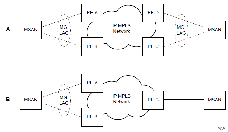
MC-LAG L2 dual homing to remote PE pairs and MC-LAG L2 dual homing to local PE pairs show different combinations of supported MC-LAG attachments. The supported configurations can be divided into the following subgroups:
dual-homing to remote PE pairs
both end-points attached with MC-LAG
one end-point attached
dual-homing to local PE pair
both end-points attached with MC-LAG
one end-point attached with MC-LAG
both end-points attached with MC-LAG to two overlapping pairs
The following figure shows dual homing to remote PE pairs.
The following figure shows dual homing to local PE pairs.
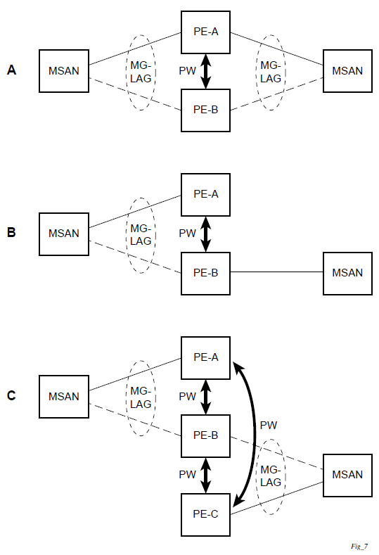
The forwarding behavior of the nodes is governed by the following principles. Note that the logical destination (actual forwarding decision) is primarily determined by the service (VPLS or VLL), and the following principle apply only if the destination or source is based on MC-LAG:
Packets received from the network will be forwarded to all local active links of the specific destination-sap based on conversation hashing. If there are no local active links, the packets will be cross-connected to the inter-chassis pseudowire.
Packets received from the MC-LAG sap will be forwarded to the active destination pseudowire or active local links of destination-sap. If no such objects are available at the local node, the packets will be cross-connected to inter-chassis pseudowire.
Point-to-point redundant connection across Layer 2/3 VPN network
The following figure shows the connection between two CPE/access nodes across network based on Layer 2/3 VPN pseudowires. The connection between a CPE/access node and a pair of access aggregation PE routers is realized by MC-LAG. From the CPE/access node perspective, a redundant pair of access aggregation PE routers acts as a single partner in LACP negotiation. At any point in time, only one of the routers has active links in a specific LAG. The status of LAG links is reflected in the status signaling of pseudowires set between all participating PEs. The combination of active and standby states across LAG links and pseudowires give only one unique path between a pair of MSANs.
Note that the configuration in the following figure shows an example configuration of VLL connections based on MC-LAG. Specifically, it shows a VLL connection where the two ends (SAPs) are located on two different redundant-pairs. However, additional configurations are possible, for example:
both ends of the same VLL connections are local to the same redundant-pair
one end of the VLL endpoint is on a redundant-pair and the other on a single (local or remote) node
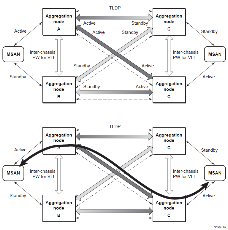
DSLAM dual homing in Layer 2 network
The following figure shows a network configuration where DSLAM is dual homed to a pair of redundant PEs by using MC-LAG. Inside the aggregation network, a redundant-pair of PEs is connecting to VPLS service, which provides a reliable connection to single or pair of Broadband Service Routers (BSRs).
PE-A and PE-B implement MC-LAG toward access. The active node synchronizes the IGMP snooping state with the standby node, allowing the standby node to forward multicast streams to receivers on the access side, if the active node fails.
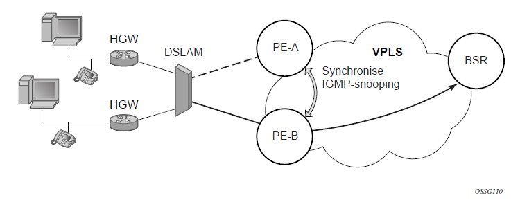
Configuration guidelines
The following guidelines apply to MC-LAG configurations:
MC-LAG peer nodes must be of the same platform type. For example, 7210 SAS-Sx/S 1/10GE can only peer with another 7210 SAS-Sx/S 1/10GE. 7210 SAS-Sx/S 1/10GE cannot be configured with 7210 SAS-Sx 10/100GE.
MC-LAG is only supported in network mode on 7210 SAS-T, 7210 SAS-Mxp, 7210 SAS-Sx/S 1/10GE, and 7210 SAS-Sx 10/100GE. For example, if two MC-LAG peers are set up using 7210 SAS-T, both need to be configured in network mode. It is not possible to have a node operating in network mode to be an MC-LAG peer with a node operating in access-uplink mode. This is true of standalone and standalone-VC modes, as well.
7210 SAS-T access-uplink mode supports active/standby LAG, which allows it to be used as client in an MC-LAG solution.
Configuring multi-chassis redundancy
When configuring associated LAG ID parameters, the LAG must be in access mode and LACP must be enabled.
Use the following syntax to configure multi-chassis redundancy features.
config>redundancy
  multi-chassis
     peer ip-address
        authentication-key [authentication-key | hash-key][hash | hash2]
        description description-string
        mc-lag
           hold-on-neighbor-failure duration
           keep-alive-interval interval
           lag lag-id lacp-key admin-key system-id system-id [remotelag lag-
id] system-priority system-priority
           no shutdown
        no shutdown
        source-address ip-address
        sync
           igmp-snooping
           port [port-id | lag-id] [sync-tag]range encap-range sync-tag
           no shutdown
config>redundancy# multi-chassis
config>redundancy>multi-chassis# peer 10.10.10.2 create
config>redundancy>multi-chassis>peer# description "Mc-Lag peer 10.10.10.2"
config>redundancy>multi-chassis>peer# mc-lag
config>redundancy>mc>peer>mc-lag# lag 1 lacp-key 32666 system-
id 00:00:00:33:33:33 system-priority 32888
config>redundancy>mc>peer>mc-lag# no shutdown
config>redundancy>mc>peer>mc-lag# exit
config>redundancy>multi-chassis>peer# no shutdown
config>redundancy>multi-chassis>peer# exit
config>redundancy>multi-chassis# exit
config>redundancy#
The following is a sample configuration output.
*7210-SAS>config>redundancy# info
----------------------------------------------
        multi-chassis
            peer 1.1.1.1 create
                shutdown
                sync
                    shutdown
                    port 1/1/1 create
                    exit
                exit
            peer 10.20.1.3 create
                mc-lag
                    lag 3 lacp-key 1 system-id 00:00:00:aa:bb:cc remote-
lag 1 system-priority 1
                    no shutdown
                exit
                no shutdown
            exit
        exit
----------------------------------------------
*7210-SAS>config>redundancy#