Network Address Translation
Terminology
-
BNG subscriber
This is a broader term than the ESM Subscriber, independent of the platform on which the subscriber is instantiated. It includes ESM subscribers on 7750 SR as well as subscribers instantiated on third party BNGs. Some of the NAT functions, such as Subscriber Aware Large Scale NAT44 utilizing standard RADIUS attribute work with subscribers independently of the platform on which they are instantiated.
-
deterministic NAT
This is a mode of operation where mappings between the NAT subscriber and the outside IP address and port-range are allocated at the time of configuration. Each subscriber is permanently mapped to an outside IP and a dedicated port block. This dedicated port block is referred to as deterministic port block. Logging is not needed as the reverse mapping can be obtained using a known formula. The subscriber’s ports can be expanded by allocating a dynamic port block in case that all ports in deterministic port block are exhausted. In such case logging for the dynamic port block allocation/de-allocation is required.
-
Enhanced Subscriber Management (ESM) subscriber
This is a host or a collection of hosts instantiated in 7750 SR Broadband Network Gateway (BNG). The ESM subscriber represents a household or a business entity for which various services with committed Service Level Agreements (SLA) can be delivered. NAT function is not part of basic ESM functionality.
-
L2-Aware NAT
In the context of 7750 SR platform combines Enhanced Subscriber Management (ESM) subscriber-id and inside IP address to perform translation into a unique outside IP address and outside port. This is in contrast with classical NAT technique where only inside IP is considered for address translations. Because the subscriber-id alone is sufficient to make the address translation unique, L2-Aware NAT allows many ESM subscribers to share the same inside IP address. The scalability, performance and reliability requirements are the same as in LSN.
-
Large Scale NAT (LSN)
This refers to a collection of network address translation techniques used in service provider network implemented on a highly scalable, high performance hardware that facilitates various intra and inter-node redundancy mechanisms. The purpose of LSN semantics is to make delineation between high scale and high performance NAT functions found in service provider networks and enterprise NAT that is usually serving much smaller customer base at smaller speeds. The following NAT techniques can be grouped under the LSN name:
-
Large Scale NAT44 or Carrier Grade NAT (CGN)
-
DS-Lite
-
NAT64
Each distinct NAT technique is referred to by its corresponding name (Large Scale NAT44 [or CGN], DS-Lite and NAT64) with the understanding that in the context of 7750 SR platform, they are all part of LSN (and not enterprise based NAT).
Large Scale NAT44 term can be interchangeably used with the term Carrier Grade NAT (CGN) which in its name implies high reliability, high scale and high performance. These are again typical requirements found in service provider (carrier) network.
-
-
NAT RADIUS accounting
This is the reporting (or logging) of address translation related events (port-block allocation/de-allocation) via RADIUS accounting facility. NAT RADIUS accounting is facilitated via regular RADIUS accounting messages (start/interim-update/stop) as defined in RFC 2866, RADIUS Accounting, with NAT specific VSAs.
-
NAT RADIUS accounting
This can be used interchangeably with the term NAT RADIUS logging.
-
NAT subscriber
In NAT terminology, a NAT subscriber is an inside entity whose true identity is hidden from the outside. There are a few types of NAT implementation in 7750 SR and subscribers for each implementation are defined as follows:
-
Large Scale NAT44 (or CGN)
The subscriber is an inside IPv4 address.
-
L2-Aware NAT
The subscriber is an ESM subscriber which can spawn multiple IPv4 inside addresses.
-
DS-Lite
The subscriber in DS-Lite can be identified by the CPE’s IPv6 address (B4 element) or an IPv6 prefix. The selection of address or prefix as the representation of a DS-Lite subscriber is configuration dependent.
-
NAT64
The subscriber is an IPv6 prefix.
-
-
non-deterministic NAT
This is a mode of operation where all outside IP address and port block allocations are made dynamically at the time of subscriber instantiation. Logging in such case is required.
-
port block
This is collection of ports that is assigned to a subscriber. A deterministic LSN subscriber can have only one deterministic port block that can be extended by multiple dynamic port blocks. Non-deterministic LSN subscriber can be assigned only dynamic port blocks. All port blocks for a LSN subscriber must be allocated from a single outside IP address.
-
port-range
This is a collection of ports that can spawn multiple port blocks of the same type. For example, deterministic port-range includes all ports that are reserved for deterministic consumption. Similarly dynamic port-range is a total collection of ports that can be allocated in the form of dynamic port blocks. Other types of port-ranges are well-known ports and static port forwards.
Network Address Translation (NAT) overview
The 7750 SR supports Network Address (and port) Translation (NAPT) to provide continuity of legacy IPv4 services during the migration to native IPv6. By equipping the multi-service ISA (MS ISA) in an IOM3-XP, the 7750 SR can operate in two different modes, known as:
Large Scale NAT
Layer 2-Aware NAT
These two modes both perform source address and port translation as commonly deployed for shared Internet access. The 7750 SR with NAT is used to provide consumer broadband or business Internet customers access to IPv4 Internet resources with a shared pool of IPv4 addresses, such as may occur around the forecast IPv4 exhaustion. During this time it, is expected that native IPv6 services are still growing and a significant amount of Internet content remains IPv4.
Principles of NAT
Network Address Translation devices modify the IP headers of packets between a host and server, changing some or all of the source address, destination address, source port (TCP/UDP), destination port (TCP/UDP), or ICMP query ID (for ping). The 7750 SR in both NAT modes performs Source Network Address and Port Translation (S-NAPT). S-NAPT devices are commonly deployed in residential gateways and enterprise firewalls to allow multiple hosts to share one or more public IPv4 addresses to access the Internet. The common terms of inside and outside in the context of NAT refer to devices inside the NAT (that is behind or masqueraded by the NAT) and outside the NAT, on the public Internet.
TCP/UDP connections use ports for multiplexing, with 65536 ports available for every IP address. Whenever many hosts are trying to share a single public IP address there is a chance of port collision where two different hosts may use the same source port for a connection. The resultant collision is avoided in S-NAPT devices by translating the source port and tracking this in a stateful manner. All S-NAPT devices are stateful in nature and must monitor connection establishment and traffic to maintain translation mappings. The 7750 SR NAT implementation does not use the well-known port range (1 to 1023).
In most circumstances, S-NAPT requires the inside host to establish a connection to the public Internet host or server before a mapping and translation occurs. With the initial outbound IP packet, the S-NAPT knows the inside IP, inside port, remote IP, remote port and protocol. With this information the S-NAPT device can select an IP and port combination (referred to as outside IP and outside port) from its pool of addresses and create a unique mapping for this flow of data.
Any traffic returned from the server uses the outside IP and outside port in the destination IP/port fields – matching the unique NAT mapping. The mapping then provides the inside IP and inside port for translation.
The requirement to create a mapping with inside port and IP, outside port and IP and protocol generally prevents new connections to be established from the outside to the inside as may occur when an inside host needs to be a server.
Traffic load balancing
NAT traffic in SR OS is distributed over ISAs and ESAs within each NAT group. As a result, NAT capacity grows incrementally by adding more ISAs and ESAs to the system while each ISA or ESA participates equally in load sharing.
SR OS load balancing mechanisms in CGN (LSN44, DS-Lite, and NAT64) differ in the upstream and downstream directions, they are independent and unaware of each other,
In the upstream direction, traffic is load balanced based on source IPv4 or IPv6 addresses or subnets.
In the downstream direction, outside IP address ranges (NAT pool address ranges) are microneted (divided into smaller subnets), and these micronets are assigned to individual ISAs or ESAs in a balanced way. Downstream traffic is assigned to each ISA or ESA based on the micronets.
Load balancing over ISAs and ESAs shows traffic load balancing within SR OS. In the upstream direction, traffic is hashed based on the source IP addresses or subnets from the10.10.0.0/16 range. A sample of 64000 source IP addresses guarantees equal load distribution.
In this example, in the downstream direction, a pool of 256 public addresses is divided into four equal subnets and each subnet is assigned to one ISA or ESA, each ISA or ESA is serving 64 public IP addresses.

If there are not enough IP addresses on the inside and outside in relation to the number of ISAs and ESAs, unequal load balancing and, in extreme cases, traffic blackholing can occur. Traffic blackholing shows an example of an extreme case, where a single IP address is assigned to a pool in a NAT group with four ISAs or ESAs. This single outside IP address can be assigned to a single ISA or ESA that serves downstream traffic. Upstream traffic is unaware of the downstream load distribution, so it sends traffic to all four ISAs and ESAs, and as a result this traffic is dropped at ISAs or ESAs that do not have the public IP address assigned.
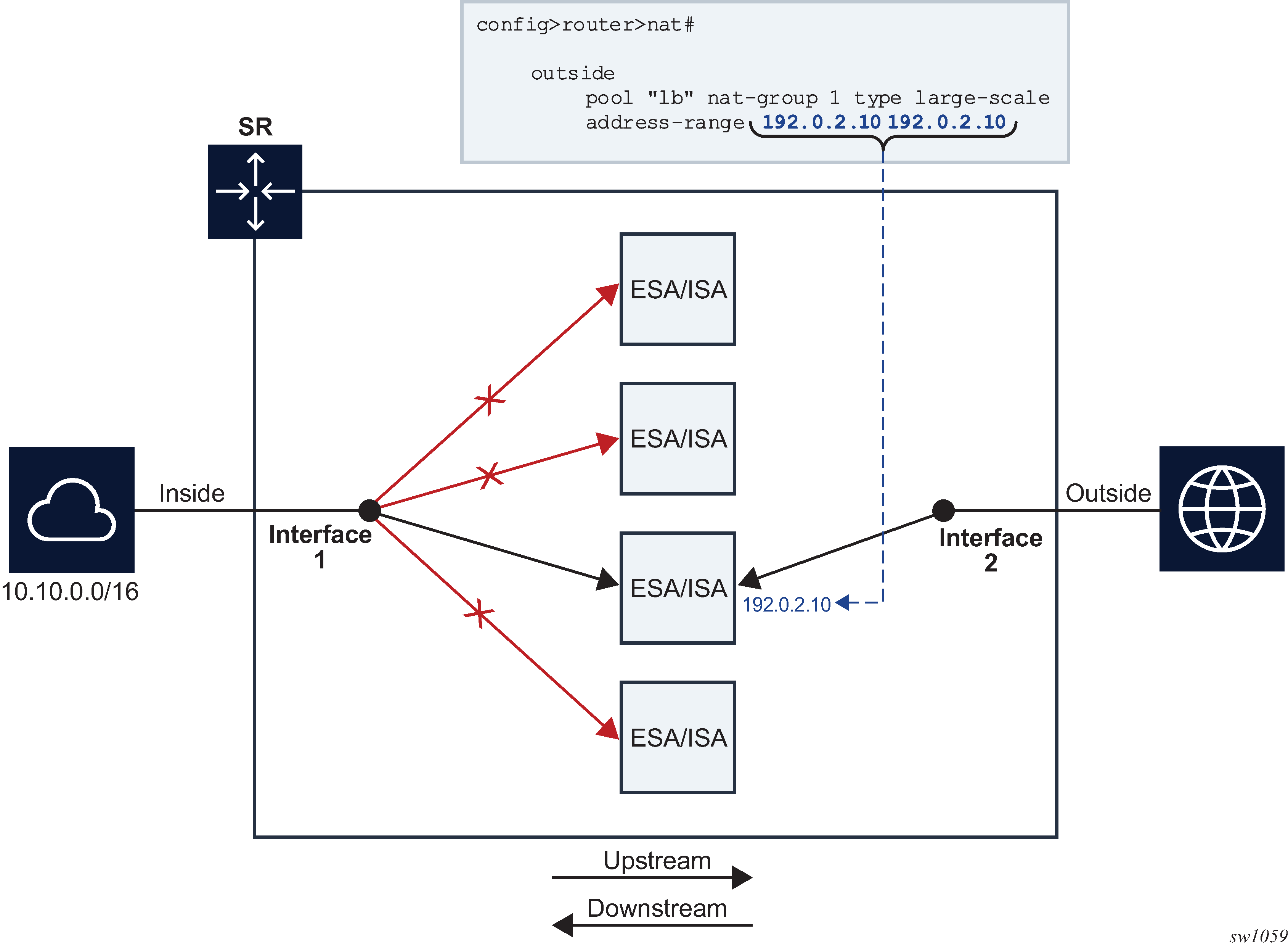
The operator is notified when the number of outside IP addresses in a pool is smaller than the number of ISAs or ESAs in the NAT group. The notification is sent in the form of a log.
3 2020/04/03 18:48:42.010 CEST MINOR: NAT #2015 Base Resource problem
"The address configuration for pool 'test.' causes one or more ISAs not getting an IP address"
4 2020/04/03 18:48:42.010 CEST MINOR: NAT #2014 Base Resource alarm raised
"The status of the NAT resource problem indication changed to true."
This configuration is permitted by the CLI, but a message is displayed directly in response to a pool activation.
configure router nat outside pool "test" no shutdown
INFO: BB #1221 The address configuration for this pool causes one or more members not getting an IP address - Router 'Base', pool 'test'
The load balancing mechanism in L2-Aware NAT relies on a different algorithm than CGN. In L2-Aware NAT, on the inside, traffic is distributed across ISAs and ESAs based on the resource utilization of each ISA or ESA. This load balancing mechanism is control plane driven, contrary to CGN which is forwarding plane driven (hashing is based purely on source IP addresses or subnets). In L2-Aware NAT, an ESM subscriber is directed to an ISA or ESA hosting a large number of subscribers, hosts, and port blocks, as an aggregate. In L2-Aware NAT, traffic is not blackholed when the number of outside IP addresses is smaller than the number of ISAs and ESAs in the pool within a single NAT group. Instead, the outside IP address is assigned to some of the ISAs or ESAs and the ESM host is directed to those. ISAs and ESAs without assigned outside IP addresses remains unused.
Application compatibility
Applications which operate as servers (such as HTTP, SMTP, and so on) or peer-to-peer applications can have difficulty when operating behind an S-NAPT because traffic from the Internet cannot reach the NAT without a mapping in place.
Different methods can be employed to overcome this, including:
Port forwarding
STUN support
Application Layer Gateways (ALG)
The 7750 SR supports all three methods following the best-practice RFC for TCP (RFC 5382, NAT Behavioral Requirements for TCP) and UDP (RFC 4787, Network Address Translation (NAT) Behavioral Requirements for Unicast UDP). Port Forwarding is supported on the 7750 SR to allow servers which operate on well-known ports <1024 (such as HTTP and SMTP) to request the appropriate outside port for permanent allocation.
STUN is facilitated by the support of Endpoint-Independent Filtering and Endpoint-Independent Mapping (RFC 4787) in the NAT device, allowing STUN-capable applications to detect the NAT and allow inbound P2P connections for that specific application. Many new SIP clients and IM chat applications are STUN capable.
Application Layer Gateways (ALG) allows the NAT to monitor the application running over TCP or UDP and make appropriate changes in the NAT translations to suit. The 7750 SR has an FTP ALG enabled following the recommendation of the IETF BEHAVE RFC for NAT (RFC 5382).
Even with these three mechanisms some applications still experience difficulty operating behind a NAT. As an industry-wide issue, forums like UPnP the IETF, operator and vendor communities are seeking technical alternatives for application developers to traverse NAT (including STUN support). In many cases the alternative of an IPv6-capable application gives better long-term support without the cost or complexity associated with NAT.
Large Scale NAT
Large Scale NAT represents the most common deployment of S-NAPT in carrier networks today, it is already employed by mobile operators around the world for handset access to the Internet.
A Large Scale NAT is typically deployed in a central network location with two interfaces, the inside toward the customers, and the outside toward the Internet. A Large Scale NAT functions as an IP router and is located between two routed network segments (the ISP network and the Internet).
Traffic can be sent to the Large Scale NAT function on the 7750 SR using IP filters (ACL) applied to SAPs or by installing static routes with a next-hop of the NAT application. These two methods allow for increased flexibility in deploying the Large Scale NAT, especially those environments where IP MPLS VPN are being used in which case the NAT function can be deployed on a single PE and perform NAT for any number of other PE by simply exporting the default route.
The 7750 SR NAT implementation supports NAT in the base routing instance and VPRN, and through NAT traffic may originate in one VPRN (the inside) and leave through another VPRN or the base routing instance (the outside). This technique can be employed to provide customers of IP MPLS VPN with Internet access by introducing a default static route in the customer VPRN, and NATing it into the Internet routing instance.
As Large Scale NAT is deployed between two routed segments, the IP addresses allocated to hosts on the inside must be unique to each host within the VPRN. While RFC1918 private addresses have typically been used for this in enterprise or mobile environments, challenges can occur in fixed residential environments where a subscriber has existing S-NAPT in their residential gateway. In these cases the RFC 1918 private address in the home network may conflict with the address space assigned to the residential gateway WAN interface. Some of these issues are documented in draft-shirasaki-nat444-isp-shared-addr-02. Should a conflict occur, many residential gateways fail to forward IP traffic.
Port range blocks
The S-NAPT service on the 7750 SR BNG incorporates a port range block feature to address scalability of a NAT mapping solution. With a single BNG capable of hundreds of thousands of NAT mappings every second, logging each mapping as it is created and destroyed logs for later retrieval (as may be required by law enforcement) could quickly overwhelm the fastest of databases and messaging protocols. Port range blocks address the issue of logging and customer location functions by allocating a block of contiguous outside ports to a single subscriber. Instead of logging each NAT mapping, a single log entry is created when the first mapping is created for a subscriber and a final log entry when the last mapping is destroyed. This can reduce the number of log entries by 5000x or more. An added benefit is that as the range is allocated on the first mapping, external applications or customer location functions may be populated with this data to make real-time subscriber identification, instead of having to query the NAT as to the subscriber identity in real-time and possibly delay applications.
Port range blocks are configurable as part of outside pool configuration, allowing the operator to specify the number of ports allocated to each subscriber when a mapping is created. When a range is allocated to the subscriber, these ports are used for all outbound dynamic mappings and are assigned in a random manner to minimize the predictability of port allocations (draft-ietf-tsvwg-port-randomization-05).
Port range blocks also serve another useful function in a Large Scale NAT environment, and that is to manage the fair allocation of the shared IP resources among different subscribers.
When a subscriber exhausts all ports in their block, further mappings are prohibited. As with any enforcement system, some exceptions are allowed and the NAT application can be configured for reserved ports to allow high-priority applications access to outside port resources while exhausted by low priority applications.
Reserved ports and priority sessions
Reserved ports allows an operator to configure a small number of ports to be reserved for designated applications should a port range block be exhausted. Such a scenario may occur when a subscriber is unwittingly subjected to a virus or engaged in extreme cases of P2P file transfers. In these situations, instead of blocking all new mappings indiscriminately, the 7750 SR NAT application allows operators to nominate a number of reserved ports and then assign a 7750 SR forwarding class as containing high priority traffic for the NAT application. Whenever traffic reaches the NAT application which matches a priority session forwarding class, reserved ports are consumed to improve the chances of success. Priority sessions could be used by the operator for services such as DNS, web portal, e-mail, VoIP, and so on, to allow these applications even when a subscriber exhausted their ports.
Preventing port block starvation
Dynamic port block starvation in LSN
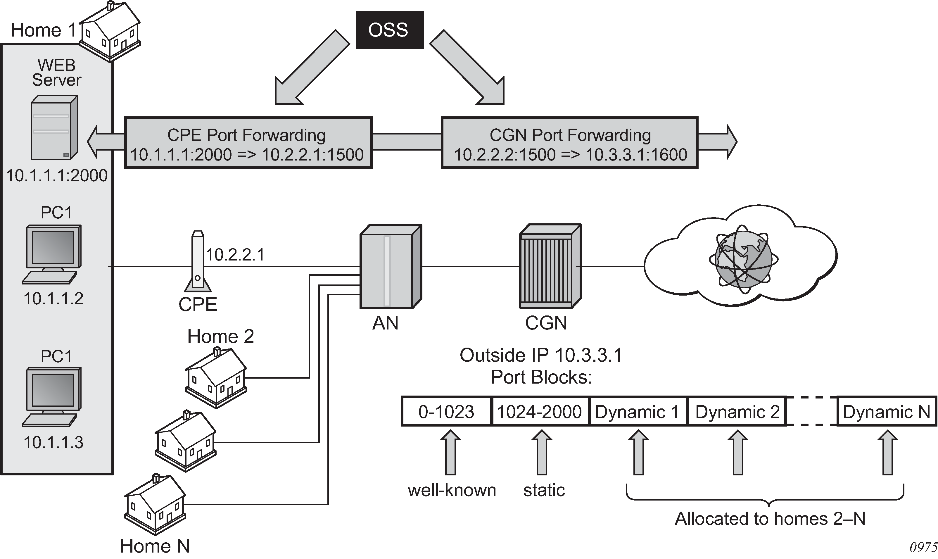
The outside IP address is always shared for the subscriber with a port forward (static or via PCP) and the dynamically allocated port block, insofar as the port from the port forward is in the range >1023. This behavior can lead to starvation of dynamic port blocks for the subscriber. An example for this scenario is shown in Dynamic port block starvation in LSN.
A static port forward for the WEB server in Home 1 is allocated in the CPE and the CGN. At the time of static port forward creation, no other dynamic port blocks for Home 1 exist (PCs are powered off).
Assume that the outside IP address for the newly created static port forward in the CGN is 10.3.3.1.
Over time dynamic port blocks are allocated for a number of other homes that share the same outside IP address, 10.3.3.1. Eventually those dynamic port block allocations exhaust all dynamic port block range for the address 10.3.3.1.
After the dynamic port blocks are exhausted for outside IP address 10.3.3.1, a new outside IP address (for example, 10.3.3.2) is allocated for additional homes.
Eventually the PCs in Home 1 come to life and they try to connect to the Internet. Because of the dynamic port block exhaustion for the IP address 10.3.3.1 (that is mandated by static port forward – Web Server), the dynamic port block allocation fails and consequently, the PCs are not able to access the Internet. There is no additional attempt within CGN to allocate another outside IP address. In the CGN there is no distinction between the PCs in Home 1 and the Web Server when it comes to source IP address. They both share the same source IP address 10.2.2.1 on the CPE.
The solution for this is to reserve a port block (or blocks) during the static port forward creation for the specific subscriber.
Dynamic port block reservation
To prevent starvation of dynamic port blocks for the subscribers that use port forwards, a dynamic port block (or blocks) is reserved during the lifetime of the port forward. Those reserved dynamic port blocks are associated with the same subscriber that created the port forward. However, a log would not be generated until the dynamic port block is actually used and mapping within that block are created.
At the time of the port forward creation, the dynamic port block is reserved in the following fashion:
If the dynamic port block for the subscriber does not exist, then a dynamic port block for the subscriber is reserved. No log for the reserved dynamic port block is generated until the dynamic port block starts being used (mapping created because of the traffic flow).
If the corresponding dynamic port block already exists, it is reserved even after the last mapping within the last port block had expired.
The reserved dynamic port block (even without any mapping) continues to be associated with the subscriber as long as the port forward for the subscriber is present. The log (syslog or RADIUS) is generated only when there is not active mapping within the dynamic port block and all port forwards for the subscriber are deleted.
Additional considerations with dynamic port block reservation:
The port block reservation should be triggered only by the first port forward for the subscriber. The subsequent port forwards do not trigger additional dynamic port block reservation.
Only a single dynamic port block for the subscriber is reserved (that is, no multiple port-block reservations for the subscriber are possible).
This feature is enabled with the configure service vprn nat outside pool port-forwarding-dyn-block-reservation and the configure router nat outside pool port-forwarding-dyn-block-reservation commands. This command can be enabled only if the maximum number of configured port blocks per outside IP is greater or equal then the maximum configured number of subscribers per outside IP address. This guarantees that all subscribers (up to the maximum number per outside IP address) configured with port forwards can reserve a dynamic port block.
If the port-reservation is enabled while the outside pool is operational and subscribers traffic is already present, the following two cases must be considered:
The configured number of subscribers per outside IP is less or equal than the configured number of port blocks per outside IP address (this is permitted) but all dynamic port blocks per outside IP address are occupied at the moment when port reservation is enabled. This leaves existing subscribers with port forwards that do not have any dynamic port blocks allocated (orphaned subscribers), unable to reserve dynamic port blocks. In this case the orphaned subscribers must wait until dynamic port blocks allocated to the subscribers without port forwards are freed.
The configured number of subscribers per outside IP is greater than the configured number of port blocks per outside IP address. In addition, all dynamic port blocks per outside IP address are allocated. Before the port reservation is even enabled, the subscriber-limit per outside IP address must be lowered (by configuration) so that it is equal or less than the configured number of port blocks per outside IP address. This action causes random deletion of subscribers that do not have any port forwards. Such subscribers are deleted until the number of subscriber falls below the newly configured subscriber limit. Subscribers with static port forwards are not deleted, regardless of the configured subscriber-limit number. When the number of subscribers is within the newly configured subscriber-limit, the port-reservation can take place under the condition that the dynamic port blocks are available. If specific subscribers with port forwards have more than one dynamic port block allocated, the orphaned subscribers must wait for those additional dynamic port blocks to expire and consequently be released.
This feature is supported on the following applications: CGN, DS-Lite and NAT64.
Timeouts
Creating a NAT mapping is only one half of the problem – removing a NAT mapping at the appropriate time maximizes the shared port resource. Having ports mapped when an application is no longer active reduces solution scale and may impact the customer experience should they exhaust their port range block. The NAT application provides timeout configuration for TCP, UDP and ICMP.
TCP state is tracked for all TCP connections, supporting both three-way handshake and simultaneous TCP SYN connections. Separate and configurable timeouts exist for TCP SYN, TCP transition (between SYN and Open), established and time-wait state. Time-wait assassination is supported and enabled by default to quickly remove TCP mappings in the TIME WAIT state.
UDP does not have the concept of connection state and is subject to a simple inactivity timer. Company-sponsored research into applications and NAT behavior suggested some applications, like the Bittorrent Distributed Hash Protocol (DHT) can make a large number of outbound UDP connections that are unsuccessful. Instead of waiting the default five (5) minutes to time these out, the 7750 SR NAT application supports an udp-initial timeout which defaults to 15 seconds. When the first outbound UDP packet is sent, the 15 second time starts – it is only after subsequent packets (inbound or outbound) that the default UDP timer becomes active, greatly reducing the number of UDP mappings.
L2-Aware NAT
L2-Aware tree shows the L2-Aware tree.
NAT is supported on DHCP, PPPoE and L2TP. Static and ARP hosts are not supported.
In an effort to address issues of conflicting address space raised in draft-shirasaki-nat444-isp-shared-addr-02, an enhancement to Large Scale NAT was co-developed to give every broadband subscriber their own NAT mapping table, yet still share a common outside pool of IPs.
Layer-2 Aware (or subscriber aware) NAT is combined with Enhanced Subscriber Management on the 7750 SR BNG to overcome the issues of colliding address space between home networks and the inside routed network between the customer and Large Scale NAT.
Layer-2 Aware NAT allows every broadband subscriber to be allocated the exact same IPv4 address on their residential gateway WAN link and then proceeds to translate this into a public IP through the NAT application. In doing so, L2-Aware NAT avoids the issues of colliding address space raised in draft-shirasaki without any change to the customer gateway or CPE.
Layer-2-Aware NAT is supported on any of the ESM access technologies, including PPPoE, IPoE (DHCP) and L2TP LNS. For IPoE both n:1 (VLAN per service) and 1:1 (VLAN per subscriber) models are supported. A subscriber device operating with L2-Aware NAT needs no modification or enhancement, existing address mechanisms (DHCP or PPP/IPCP) are identical to a public IP service, the 7750 SR BNG simply translates all IPv4 traffic into a pool of IPv4 addresses, allowing many L2-Aware NAT subscribers to share the same IPv4 address.
More information about L2-Aware NAT can be found in draft-miles-behave-l2nat-00.
Port block extensions
Similarly to LSN, an L2-Aware NAT subscriber is assigned a single outside IP address per NAT pool, with one or more port blocks tied to the IP address. The outside IP address is shared by multiple subscribers, each with its own unique set of port blocks.
To ensure that a predetermined number of subscribers receive NAT service, an outside IP address and at least one port block on that IP address must be guaranteed. For this reason, the port blocks space in a pool is divided into two partitions:
port block space reserved for new L2-Aware NAT subscribers
Each new subscriber is guaranteed to receive at least one port block, referred to as the initial port block. The keyword is a predetermined number of subscribers who are guaranteed at least one port block. This number is defined by the subscriber-limit multiplied by the number of outside addresses in a pool. If the overall number of subscribers in the network requiring the NAT service is larger, then the guaranteed PB space becomes oversubscribed.
port block space reserved for the extended port-blocks of existing NAT subscribers
This port partition can be used by subscribers who exhaust their ports in the initial port block and need additional ports. Pending on the availability and configuration, they are assigned additional port blocks.
Without this type of port space partitioning, the outside IP addresses and the NAT pool may become overtaken by users with heavier port consumption. This denies access to NAT services to a majority of users with lower port consumption.
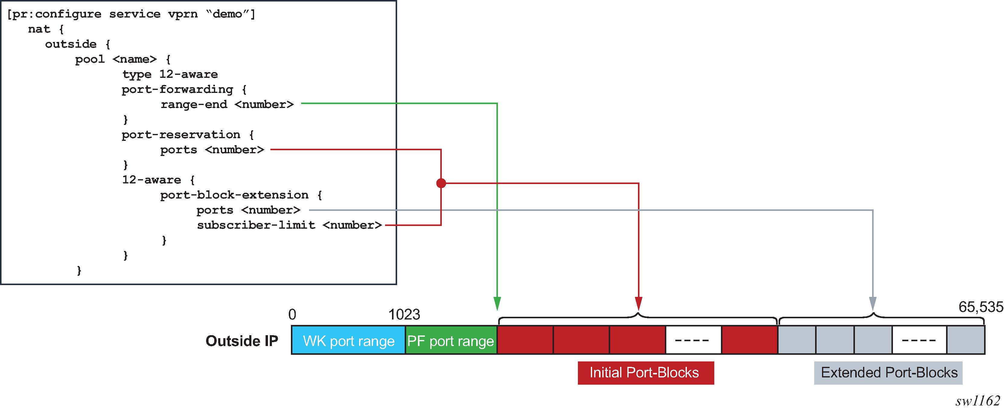
This division of port space is controlled by limiting the number of subscribers per an outside IP address and configuring the size of the initial port block.
The following shows configuration information relevant to port-block allocation in L2-Aware NAT:
initial port block size for new subscribers
MD-CLI
    configure service vprn <service-name> nat outside pool <name>
        port-reservation {
            ports <number>
        }
Classic CLI
The pool name must be type l2-aware.
port-reservation blocks num can be set only if port-block-extension is not enabled.
    configure service vprn <id> nat outside pool <name>
        port-reservation blocks <num>
        port-reservation ports <num>
the extended port block size for existing subscribers and the maximum number of subscribers per outside IP address. The size of the initial port blocks and extended port block may differ.
MD-CLI
    configure service vprn <service-name> nat outside pool <name>
        l2-aware {
            port-block-extension {
                ports <number>
                subscriber-limit <number>
            }
        }
Classic CLI
The pool name must be type l2-aware.
    configure service vprn <id> nat outside pool <name>
        port-block-extensions ports <num> subscriber-limit <num>
upper boundary for static port forwards
MD-CLI
    [configure service vprn <service-name> nat outside pool <name>]
        port-forwarding {
            range-end <number>
        }
Classic CLI
    configure service vprn <id> nat outside pool <name>
        port-forwarding-range <range-end>
Port space partitioning for an outside IP address shows the effects of the commands.
The maximum number of port blocks that can be allocated per subscriber is controlled by the following configuration in the NAT policy.
MD-CLI
    [configure service nat nat-policy <name>]
        block-limit <number>
Classic CLI
    configure service nat nat-policy <name>
        block-limit <number>
Managing port block space
Both port partitions, initial and extended, are served on a first-come-first-served basis. The initial port partition guarantees at least one port block for each of the preconfigured number of subscribers per outside IP address (configure router nat outside pool port-block-extension ports num-ports subscriber-limit number command). If there are more subscribers in the network than the preconfigured number of NAT subscribers, then this space becomes oversubscribed.
Extended port partitioning, however, does not guarantee that each of the existing NAT subscriber receives additional port blocks. Each subscriber can allocate additional free port blocks only if they are available, up to the maximum combined limit (initial and extended) set in the NAT policy (configure service nat nat-policy block-limit command).
For optimized NAT pool management and correct capacity planning, understanding the following parameters in the operator’s network is essential:
IP address compression ratio (the number of subscribers who share one outside IP address)
subscriber oversubscription ratio (the number of NAT subscribers who are active simultaneously)
statistical port usage for subscribers (the percentage of subscribers who are heavy, medium, and light port users)
port block sizes
Based on the previous parameters, an average port block per subscriber can be determined and the following parameters in NAT can be set:
the subscriber limit per outside IP address configured in the NAT pool
the size of the initial and extended port blocks configured in the NAT pool
the maximum number of port blocks per subscriber configured in NAT policy
the outside IP address range configured in the NAT pool
The following are reasonable guidelines with an example that can serve as an initial configuration for operators who are unsure of their current traffic patterns in terms of port usage for their subscribers.
An operator has 10,000 subscribers that require NAT, but only 8,000 of them are active simultaneously. This means that the operator can allow oversubscription of outside (NAT) IP address.
Average port usage:
60% of the subscribers are light port users with less than 1000 ports.
30% of the subscribers are medium port users with less than 2000 ports.
10% of the subscribers are heavy port users with less than 4000 ports.
These assumptions lead to the following calculations:
8,000 active subscribers x (0.6 x 1000 + 0.3 x 2,000 + 0.1 x 4,000) = 12,800,000 total ports.
Consider that one outside IP address can accommodate ~50,000 (64K ports less the static port forwards and well known ports). This yields 256 outside IP addresses (/24) in a pool therefore, 12,800,000 / 50,000 = 256.
The compression ratio is 8,000 divided by 256 equals ~32 (32 subscribers share one outside IP address), therefore the subscriber limit equals 32.
Based on this calculation, a reasonable size for the initial port block size is 1000 ports and the extended port block size is 335 ports.
The maximum number of port blocks per subscriber is set to 10 to accommodate heavy users with 4,000 ports (1000 + 9 x 335 = 4015)
Setting the subscriber limit in a pool to 32, the initial and extended port block sizes to 1000 and 335 respectively, the maximum number of port blocks per subscriber to 10, and configuring a /24 address range in a pool would produce the needed results. This assumes that the subscribers are properly load-balanced over ISAs or ESAs. The following is an example configuration.
    [configure service vprn ‟demo vprn” nat outside pool ‟demo pool”]
        port-reservation {
            ports 1000
        }
        l2-aware {
            port-block-extension {
            ports 335
            subscriber-limit 32
            }
        }
        port-forwarding {
            range-end 15000
        }

    [configure service nat nat-policy ‟demo-policy”]
        block-limit 10
L2-Aware NAT bypass
L2-Aware NAT bypass refers to the functionality where the entire or partial traffic from a L2-Aware-NAT-enabled ESM1 subscriber circumvents local NAT function. There are three types of bypass supported for L2-Aware NAT in the SR OS:
full ESM host bypass
selective ESM host bypass based on an IP filter match
the entire ESM subscriber bypass because of ISA/ESA failure. This type of bypass is described in NAT redundancy.
Full ESM host bypass
In this type of bypass, a subscriber host is implicitly excluded from L2-Aware NAT if its IP address falls outside of the configured subnet in the inside NAT CLI hierarchy under the L2-Aware CLI node.
In the following example, the address under the L2-Aware CLI node (address 10.10.1.254/24) represents the default gateway and a L2-Aware subnet. Hosts with IP addresses within the configured L2-Aware subnet (in this example 10.10.1.0/24) are subjected to L2-Aware NAT (the exception is the default gateway address 10.10.1.254). Hosts outside of this IP range bypass NAT. In this way, a mix of hosts under the same L2-Aware enabled ESM subscriber can coexist, some of which are subject to NAT, and some of which are bypassing NAT.
configure
     router
          nat
               inside
                    l2-aware
                         address 10.10.1.254/24
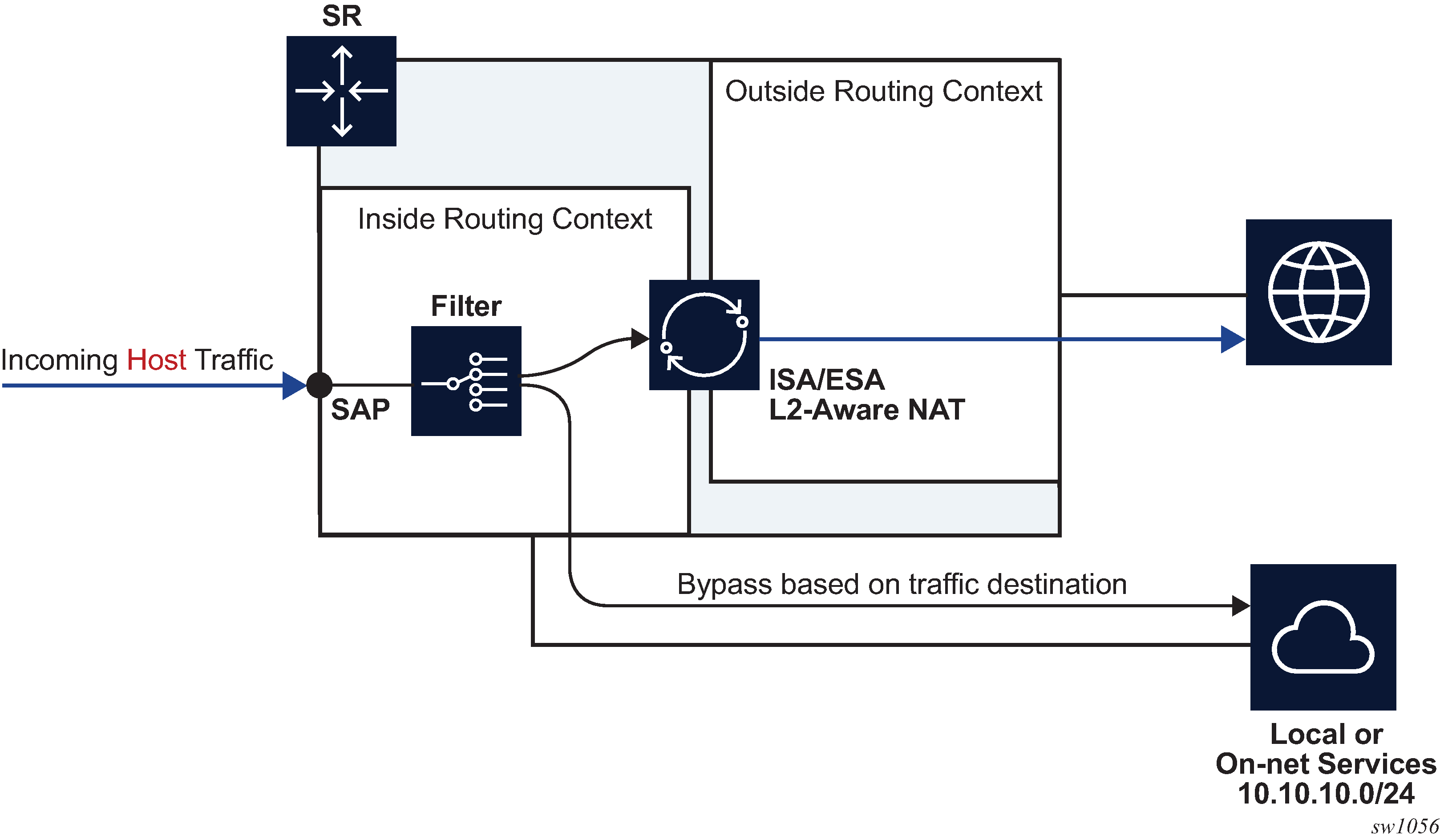
Selective L2-Aware NAT bypass
In selective L2-Aware NAT bypass, a decision whether to perform NAT is made based on the traffic classifiers (match conditions) defined in an IP filter applied to an ESM host.
A typical use case for selective L2-Aware NAT bypass is based on destinations, where on-net services are needed to be accessed without NAT, while some other off-net destinations, require NAT. Traffic to those on-net services is identified based on the destination IP addresses (L2-Aware bypass based on traffic destination).
L2-Aware NAT subscribers that are candidates for selective bypass in the SR OS, must be first identified and enabled with the config>subscr-mgmt>sub-prof>nat-allow-bypass command:
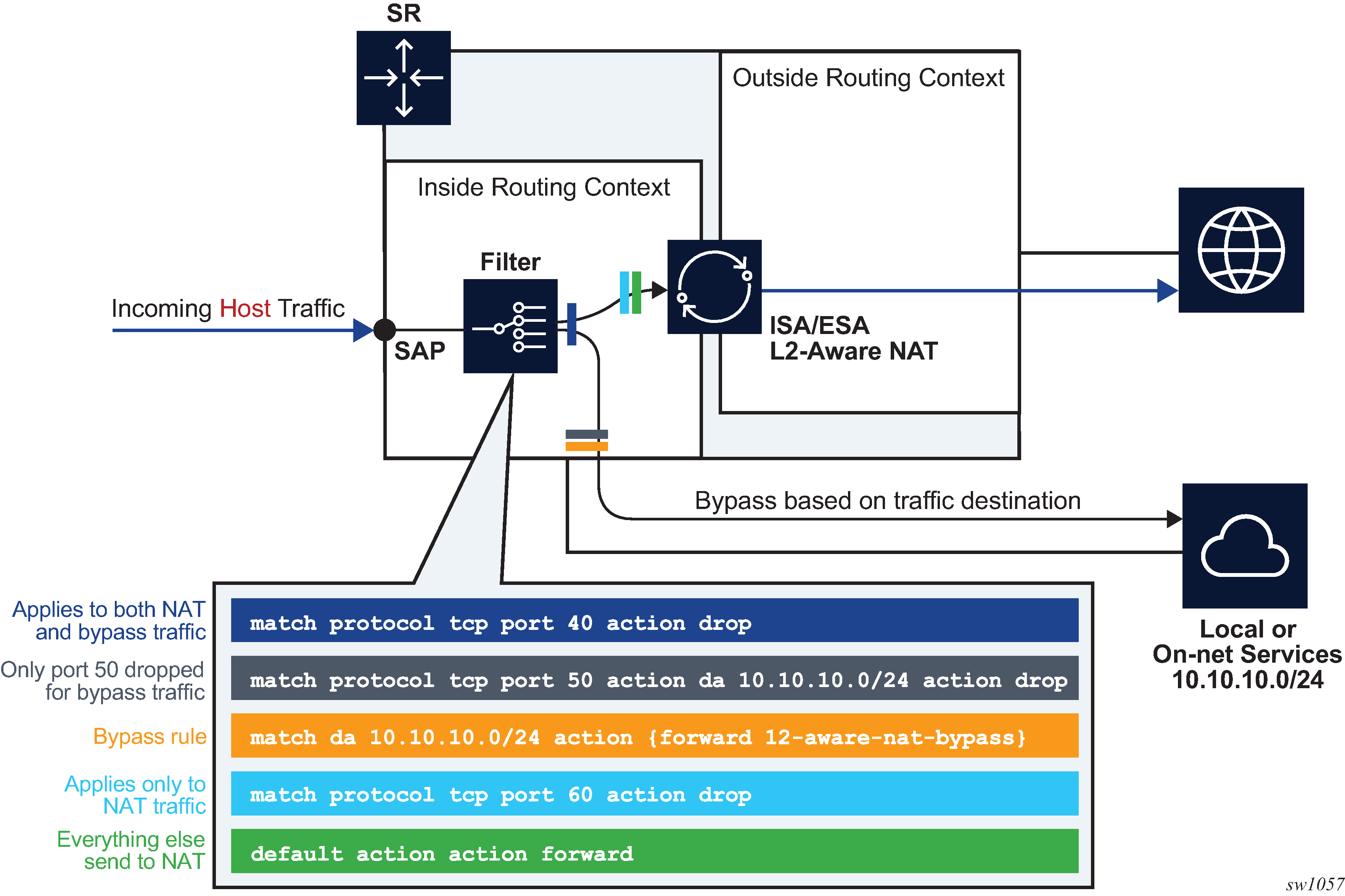
After the selective L2-Aware NAT bypass is enabled, the determination of whether specific traffic from a host bypasses NAT comes via an IP filter with a newly defined action l2-aware-nat-bypass. This new action must be configured in addition to the existing action accept (in MD-CLI) or forward (in classic CLI). This defined set of actions divert identified traffic away from NAT.
Although most typical use cases require traffic identification based on destination IP addresses, generic match statements in IP filters allow identification of traffic based on any Layer 3 fields.
The filter entries are executed in top-to-bottom order as shown in Filtering example for L2-Aware NAT bypass.
Configuration options for selective L2-Aware NAT bypass describes the behavior in relation to the three configuration options that directly influence selective L2-Aware NAT bypass.
| L2-Aware NAT-enabled host | Selective bypass enabled | IP filter action l2-aware-nat-bypass accept | forward |
Behavior |
|---|---|---|---|
Yes |
Yes |
Yes |
Selective bypass is in effect |
Yes |
Yes |
No |
The host is enabled for bypass, but without the corresponding IP filter action. Bypass is not in effect and all traffic from the host is NAT’d. After the bypass action is provided via the IP filter, traffic identified in the IP filter is bypassed. |
Yes |
No |
Yes |
The host is not enabled for bypass, but the IP filter is configured for bypass. This is an incorrect condition where host traffic is bypassed in the upstream direction but not in the downstream direction. As a result, downstream traffic is dropped. |
Yes |
No |
No |
The host is not enabled for bypass. All host traffic is NAT’d. |
No |
Yes |
Yes |
The host is not an L2-Aware NAT host. This is a full bypass case. |
No |
Yes |
No |
The host is not an L2-Aware NAT host. This is a full bypass case. |
No |
No |
Yes |
The host is not an L2-Aware NAT host. This is full bypass case. |
No |
No |
No |
The host is not an L2-Aware NAT host. This is full bypass case. |
The following are configuration considerations:
An ESM-enabled host can be enabled if the following two conditions are met:
The subscriber’s sub-profile contains the nat-policy name command.
The host IP address belongs to the subnet configured under the address command:
configure
    router/service vprn
        nat
            inside
                l2-aware
                    address <ip-address/mask>
-
Selective bypass is enabled if the configure subscriber-mgmt sub-profile nat-allow-bypass command is configured under the sub-profile.
-
All configuration options are allowed in the CLI and it is up to the operator to consult Configuration options for selective L2-Aware NAT bypass for expected results.
On-line change of the selective NAT bypass
While traffic is flowing, it is possible to change its path from going through NAT to bypassing NAT. This kind of transition while traffic is flowing is referred to as on-line change.
NAT bypass for L2-Aware NAT subscriber can be influenced with two configuration parameters (configure subscr-mgmt sub-prof nat-access-mode and configure filter ip-filter entry action l2-aware-nat-bypass). Configuration options for selective L2-Aware NAT bypass lists possible (valid and invalid) combinations of the two.
Enabling and disabling NAT bypass (config>subscr-mgmt>sub-prof>nat-access-mode), is supported by changing the subscriber profile for the ESM subscriber with RADIUS/Gx. However, changing the subscriber profile configuration with CLI while the profile is in use is not allowed.
The recommend method to change the IP filter action (l2-aware-nat-bypass) is to override the existing IP filter using RADIUS or Gx.
For additional restrictions when using this feature, see Known Limitations section in the Release Notes.
NAT bypass verification
To verify that NAT bypass is in effect, use the following show service active-subscribers detail and show filter ip commands.
*A:Dut-C# show service active-subscribers detail
===============================================================================
Active Subscribers
===============================================================================
-------------------------------------------------------------------------------
Subscriber AL_x0ffx6x0x0x2
           (sub_l2-dhcp1)
-------------------------------------------------------------------------------
NAT Policy    : pol-B-1
Outside IP    : 130.0.0.201
Ports         : 1536-1570
NAT Policy    : pol-o-1
Outside IP    : 19.0.0.87 (vprn101)
Ports         : 1024-1055
NAT Policy    : pol-o1-1
Outside IP    : 130.0.0.68 (vprn601)
Ports         : 1152-1349
NAT Policy    : pol-o2-1
Outside IP    : 130.0.0.222 (vprn602)
Ports         : 1152-1349
-------------------------------------------------------------------------------
I. Sched. Policy : N/A
E. Sched. Policy : N/A                              E. Agg Rate Limit: Max
                                                    E. Min Resv Bw   : 1
I. Policer Ctrl. : N/A
E. Policer Ctrl. : N/A
I. vport-hashing : Disabled
I. sec-sh-hashing: Disabled
Q Frame-Based Ac*: Disabled
Acct. Policy     : N/A                              Collect Stats    : Disabled
ANCP Pol.        : N/A
Accu-stats-pol   : (Not Specified)
HostTrk Pol.     : N/A
IGMP Policy      : N/A
MLD Policy       : N/A
PIM Policy       : N/A
Sub. MCAC Policy : N/A
NAT Policy       : pol-o-1
Firewall Policy  : N/A
UPnP Policy      : N/A
NAT Prefix List  : npl-4
Allow NAT bypass : Yes
This command shows that the ESM subscriber is a L2-Aware NAT subscriber for which bypass is enabled.
The following command provides insight into whether the NAT bypass is in effect:
*A:Dut-A>config>filter# show filter ip 10
===============================================================================
IP Filter
===============================================================================
Filter Id           : 10                           Applied        : Yes
Scope               : Template                     Def. Action    : Drop
Type                : Normal
System filter       : Unchained
Radius Ins Pt       : n/a
CrCtl. Ins Pt       : n/a
RadSh. Ins Pt       : n/a
PccRl. Ins Pt       : n/a
Entries             : 1
Description         : (Not Specified)
Filter Name         : 10
-------------------------------------------------------------------------------
Filter Match Criteria : IP
-------------------------------------------------------------------------------
Entry               : 1
Description         : (Not Specified)
Log Id              : n/a
Src. IP             : 0.0.0.0/0
Src. Port           : n/a
Dest. IP            : 0.0.0.0/0
Dest. Port          : n/a
Protocol            : Undefined                    Dscp           : Undefined
ICMP Type           : Undefined                    ICMP Code      : Undefined
Fragment            : Off                          Src Route Opt  : Off
Sampling            : Off                          Int. Sampling  : On
IP-Option           : 0/0                          Multiple Option: Off
Tcp-flag            : (Not Specified)
Option-pres         : Off
Egress PBR          : Disabled
Primary Action      : Forward
L2 Aware NAT Bypass : Enabled
Ing. Matches        : 0 pkts
Egr. Matches        : 0 pkts
===============================================================================
L2-Aware NAT destination-based multiple NAT policies
Multiple NAT policies for a L2-Aware subscriber can be selected based on the destination IP address of the packet. This allows the operator to assign different NAT pools and outside routing contexts based on the traffic destinations.
The mapping between the destination IP prefix and the NAT policy is defined in a nat-prefix-list. This nat-prefix-list is applied to the L2-Aware subscriber through a subscriber profile. After the subscriber traffic arrives to the MS-ISA where NAT is performed, an additional lookup based on the destination IP address of the packet is executed to select the specific NAT policy (and consequently the outside NAT pool). Failure to find the specific NAT policy based on the destination IP address lookup results in the selection of the default NAT policy referenced in the subscriber profile.
CLI example:
--------------------------------------------------
echo "Service Configuration"
#--------------------------------------------------
service
   nat
     nat-policy "l2aw nat policy" create
       pool "l2aw-nat-pool" router 1
     exit
     nat-policy "another-l2aw-nat-policy" create
        pool "another-l2aw-nat-pool" router 2
     exit
nat-policy "default-nat-policy" create
        pool "default-nat-pool" router Base
     exit

     nat-prefix-list "prefixlist1" application l2-aware-dest-to-policy create
        prefix 192.168.0.0/30 nat-policy "l2aw-nat-pol"
          prefix 192.168.0.64/30 nat-policy "l2aw-nat-pol"
          prefix 192.168.0.128/30 nat-policy "l2aw-nat-pol"
          prefix 192.168.1.0/30 nat-policy "another-l2aw-nat-pol"
          prefix 192.168.1.64/30 nat-policy "another-l2aw-nat-pol"
          prefix 192.168.1.128/30 nat-policy "another-l2aw-nat-pol"
        exit
    exit
#--------------------------------------------------
echo "Subscriber-mgmt Configuration"
#--------------------------------------------------
    subscriber-mgmt
        sub-profile "sub_profile" create
            nat-policy "def-nat-policy"
            nat-prefix-list "prefixlist1"
        exit
As displayed in the example, multiple IP prefixes can be mapped to the same NAT policy.
The NAT prefix list cannot reference the default NAT policy. The default NAT policy is the one that is referenced directly under the subscriber profile.
Logging
In L2-Aware NAT with multiple nat-policies, the NAT resources are allocated in each pool associated with the subscriber. This NAT resource allocation is performed at the time when the ESM subscriber is instantiated. Each NAT resource allocation is followed by log generation.
For example, if RADIUS logging is enabled, one Alc-NAT-Port-Range VSA per NAT policy is included in the acct START/STOP message.
[Alc-Nat-Port-Range = "192.168.20.1 1024-1055 router base nat-pol-1"
Alc-Nat-Port-Range = "193.168.20.1 1024-1055 router base nat-pol-2".
Alc-Nat-Port-Range = "194.168.20.1 1024-1055 router base" nat-pol-3.]
RADIUS logging and NAT-policy change via CoA
Nat-policy change for L2-Aware NAT is supported through a sub-profile change triggered in CoA. However, change of sub-profile alone through CoA does not trigger generation of a new RADIUS accounting message and therefore NAT events related to NAT policy changes are not promptly logged. For this reason, each CoA initiating the sub-profile change in a NAT environment must do one of the following:
Change the sla-profile.
Include the Alc-Trigger-Acct-Interim VSA in the CoA messages.
Note that the sla-profile has to be changed and not just refreshed. In other words, replacing the existing sla-profile with the same one does not trigger a new accounting message.
Both of these events trigger an accounting update at the time CoA is processed. This keeps NAT logging current. The information about NAT resources for logging purposes is conveyed in the following RADIUS attributes:
-
Alc-Nat-Port-Range-Freed VSA → NAT resources released because of CoA.
-
Alc-Nat-Port-Range VSA → NAT resources in use. These can be the existing NAT resources which were not affected by CoA or they can be new NAT resource allocated because of CoA.
NAT logging behavior because of CoA depends on the deployed accounting mode of operation. This is described in NAT-policy change and CoA in L2Aware NAT. The interim-update keyword must be configured for host/session accounting for Interim-Update messages to be triggered:
configure
   subscriber-mgmt
      radius-accounting-policy <name>
         session-accounting interim-update
configure
   subscriber-mgmt
      radius-accounting-policy <name>
         host-accounting interim-update
Table Legend:
AATR (Alc-Acct-Triggered-Reason) VSA — This VSA is optionally carried in Interim-Update messages that are triggered by CoA.
ATAI (Alc-Trigger-Acct-Interim) VSA — this VSA can be carried in CoA to trigger Interim-Update message. The string carried in this VSA is reflected in the triggered Interim-Update message.
I-U (Interim-Update Message)
| Host or session accounting | Queue-instance accounting | Comments | |
|---|---|---|---|
|
CoA Sub-prof change + ATAI VSA |
Single I-U with:
|
Single I-U with:
|
Single I-U message is triggered by CoA. |
|
CoA Sub-profile change + Sla-profile change |
First I-U:
Second I-U:
|
Acct Stop:
Acct Start:
|
Two accounting messages are triggered in succession. |
|
CoA Sub-profile change |
— |
— |
No accounting messages are triggered by CoA. The next regular I-U messages contain:
|
|
CoA Sub-profile change+ Sla-profile-change + ATAI VSA |
First I-U:
Second I-U:
|
Acct Stop:
Acct Start:
|
Two accounting messages are triggered in succession. |
For example, the second CoA row describes the outcome triggered by CoA carrying new sub and sla profiles. In host/session accounting mode this creates two Interim-Update messages. The first Interim-Messages carries information about:
-
the released NAT resources at the time when CoA is activated
-
existing NAT resources that are not affected by CoA
-
new NAT resources allocated at the time when CoA is activated
The second Interim-Update message carries information about the NAT resources that are in use (existing and new) when CoA is activated.
From this, the operator can infer which NAT resources are released by CoA and which NAT resources continue to be in use when CoA is activated.
Delay between the NAT resource allocation and logging during CoA
Nat-policy change induced by CoA triggers immediate log generation (for example acct STOP or INTERIM-UPDATE) indicating that the nat resources have been released. However, the NAT resources (outside IP addresses and port-blocks) in SR OS are not released for another five seconds. This delay is needed to facilitate proper termination of traffic flow between the NAT user and the outside server during the NAT policy transition. A typical example of this scenario is the following:
-
HTTP traffic is redirected to a WEB portal for authentication. Only when the user is authenticated, access to the Internet is granted along with a new NAT policy that provides more NAT resources (larger port-ranges, and so on).
-
After the user is authenticated, CoA is used to change the user forwarding properties (HTTP-redirect is removed and the NAT policy is changed). However, CoA must be sent before the authentication acknowledgment (ACK) messages is sent, otherwise the next new HTTP request would be redirected again.
-
Authentication acknowledgment is sent to the NAT user following the CoA which removed the HTTP redirect and instantiated a new NAT policy. Because the original communication between the WEB portal and the NAT user was relying on the original NAT policy, the NAT resources associated with the original NAT policy must be preserved to terminate this communication gracefully. Therefore, the delay of five seconds before the NAT resources are freed.
Similar to other stale dynamic mappings, stale port forwards are released after five seconds. Note that static port forwards are kept on the CPM. New CoAs related to NAT are rejected (NAK’d) in case that the previous change is in progress (during the 5seconds interval until the stale mappings are purged).
Static port forwards
Unless the specific NAT policy is provided during Static Port Forward (SPF) creation (SPF creation command), the port forward is created in the pool referenced in the default NAT policy. Nat-policy can be part of the command used to modify or delete SPF. If the NAT policy is not provided, then the behavior is:
If there is only one match, the port forward is modified or deleted.
If there is more than one match, modify or delete port forward must specify a NAT policy. Otherwise, the modify or delete action fails.
A match is considered when at least these parameters from the modify or delete command are matched (mandatory parameters in the spf command):
subscriber identification string
inside IP address
inside port
protocol
For a Layer 2-Aware NAT, an alternative AAA interface can be used to specify SPF. An alternative AAA interface and CLI-based port forwards are mutually exclusive. See the 7450 ESS, 7750 SR, and VSR RADIUS Attributes Reference Guide for more details.
L2-Aware ping
Similar to the non-L2-Aware ping command, understanding how the ICMP Echo Request packets are sourced in L2-Aware ping is crucial for the correct execution of this command and the interpretation of its results. The ICMP Echo Reply packets must be able to reach the source IP address that was used in ICMP Echo Request packets on the SR OS node on which the L2-Aware ping command was executed. See L2-Aware ping.
The return packet (the ICMP Echo reply sent by the targeted host) is subject to L2- Aware NAT routing executed in the MS-ISA. The L2-Aware NAT routing process looks at the destination IP address of the upstream packet and then directs the packet to the correct outside routing context. The result of this lookup is a NAT policy that references the NAT pool in an outside routing context. This outside routing context must be the same as the one from which the L2-Aware ping command was sourced. Otherwise, the L2-Aware ping command fails.
The L2-Aware ping command can be run in two modes:
basic mode (ping ip-address subscriber subscriber-id) in which the subscriber-id is a required field to differentiate subscriber hosts that assigned the same IP address (although each host has its own instantiation of this IP address)
-
extended mode where additional parameters can be selected. The two most important being the source IP address (source) and the routing context (router):
ping ip-address subscriber subscriber-id source ip-address router router-id
L2-Aware ping shows the traffic flow for an L2-Aware ping command targeting the subscriber’s IP address 10.2.3.4, sourced from the Base routing context using an arbitrary source IP address of 10.6.7.8 (it is not required that this IP address belong to the L2-Aware ping originating node).
When the host 10.2.3.4 replies, the incoming packets with the destination IP address of 10.6.7.8 are matched against the destination-prefix 10.6.7.0/24 referencing the nat-policy-1. nat-policy-1 contains the Pool B which resides in the Base routing context. Hence, the loop is closed and the execution of the L2-Aware ping command is successful.

L2-Aware ping is always sourced from the outside routing context, never from the inside routing context. If the router is not specifically configured as an option in the L2-Aware ping command, the Base routing context is selected by default. If that the Base routing context is not one of the outside routing contexts for the subscriber, the L2-Aware ping command execution fails with the following error message:
‟MINOR: OAM #2160 router ID is not an outside router for this subscriber.”
UPnP
UPnP uses the default NAT policy.
NAT pool addresses and ICMP Echo Request/Reply (ping)
The outside IPv4 addresses in a NAT pool can be configured to answer pings. ICMPv4 Echo Requests are answered with ICMPv4 Echo Replies.
In 1:1 NAT, ICMP Echo Requests are propagated to the host on the inside. The host identified by a NAT binding then answers the ping.
In Network Address Port Translation (NAPT), ICMP Echo Requests are not propagated to the hosts behind the NAT. Instead, the reply is issued by the SR OS from the ESA or ISA.
In NAPT, the behavior is as follows:
In L2-aware NAT when port-block-extensions is disabled, the reply from an outside IP address is generated only when the IP address has at least one host (binding) behind it.
In L2-aware NAT when port-block-extensions is enabled, the reply from an outside IP address is generated regardless if a binding is present.
In LSN, the reply from an outside IP address is generated regardless if a binding is present.
For security reasons, the ICMP Echo Reply functionality is disabled by default. The following commands enable the behavior:
Classic CLI
configure
   router
      nat
         outside
            pool <name> nat-group <id> type <large-scale|l2-aware|wlan-gw-anchor>
               [no] icmp-echo-reply
MD-CLI
configure {
   router ‟Base”  | service vprn <name> {
      nat {
         outside {
            pool <name> {

               icmp-echo-reply <boolean>
            }
         }
      }
   }
}
This functionality is on a per pool basis and it can be configured online while the pool is enabled.
Traffic steering to NAT
Traffic steering to NAT refers to the mechanism by which traffic in the SR line card is redirected to the ISA or VM-ESA for NAT processing. This traffic must be identified first and then redirected to ISA or VM-ESA. The mechanism by which traffic is steered to NAT in an SR node in the upstream direction depends on the NAT type.
For LSN44, the upstream traffic (in the private to public direction) is steered (or redirected) to NAT in an SR node through one of the two mechanisms:
routing
filters
Both methods are applied in the inside (private) routing context. Traffic matched through routing or filter criteria is sent to the ISA or VM-ESA for NAT processing and from there to the outside (public) routing context where it exits the node.
In NAT64 and DS-lite, traffic is steered to NAT mainly through routing NAT64 prefix in NAT64 and Address Family Transition Router (AFTR) IPv6 address in DS-lite. However, the routing can be augmented with IPv6 filters to accommodate mapping to multiple NAT pools per subscriber.
In L2-Aware, where NAT is integrated with ESM, traffic is steered to NAT automatically assuming that the subscriber session is associated with NAT during session instantiation phase.
In all NAT types, the downstream traffic arriving in the outside (public) routing context is forwarded to NAT through routing and public pool IPv4 addresses are installed in the routing table with the next hop pointing to the ISA or VM-ESA.
The following sections describe steering logic for LSN44 which is the only NAT type that supports dynamic routing.
Routing approach in LSN44
Routing approach relies on destination IP-based match. A destination IP route leading to NAT can be static (specifically configured) or dynamic (installed through the BGP routing protocol).
Static NAT routes
Static steering to LSN44 is based on the destination-prefix command with a statically-configured routing prefix in an inside routing context (VPRN or GRT). This static route points to an ISA or VM-ISA. In transit from the inside routing context to the outside routing context, frames must be redirected through an ISA or VM-ESA where NAT is performed.
If there are multiple ISA or VM-ESAs in a NAT group, an internal LAG per NAT group is used with member ports connected to each ISA or VM-ESA. Upstream traffic is load-balanced between the ISAs or VM-ESAs based on the source IP addresses or prefixes.
The CLI configuration used for static steering to LSN44 is shown in Basic CLI for NAT where a NAT policy containing a pool name and the outside routing context acts as a bond between the inside routing context and the outside routing context. A destination-prefix without an explicitly configured NAT policy uses a default NAT policy. As shown in Basic CLI for NAT, the prefix 192.168.1.0/24 is mapped to nat-policy cgn2.
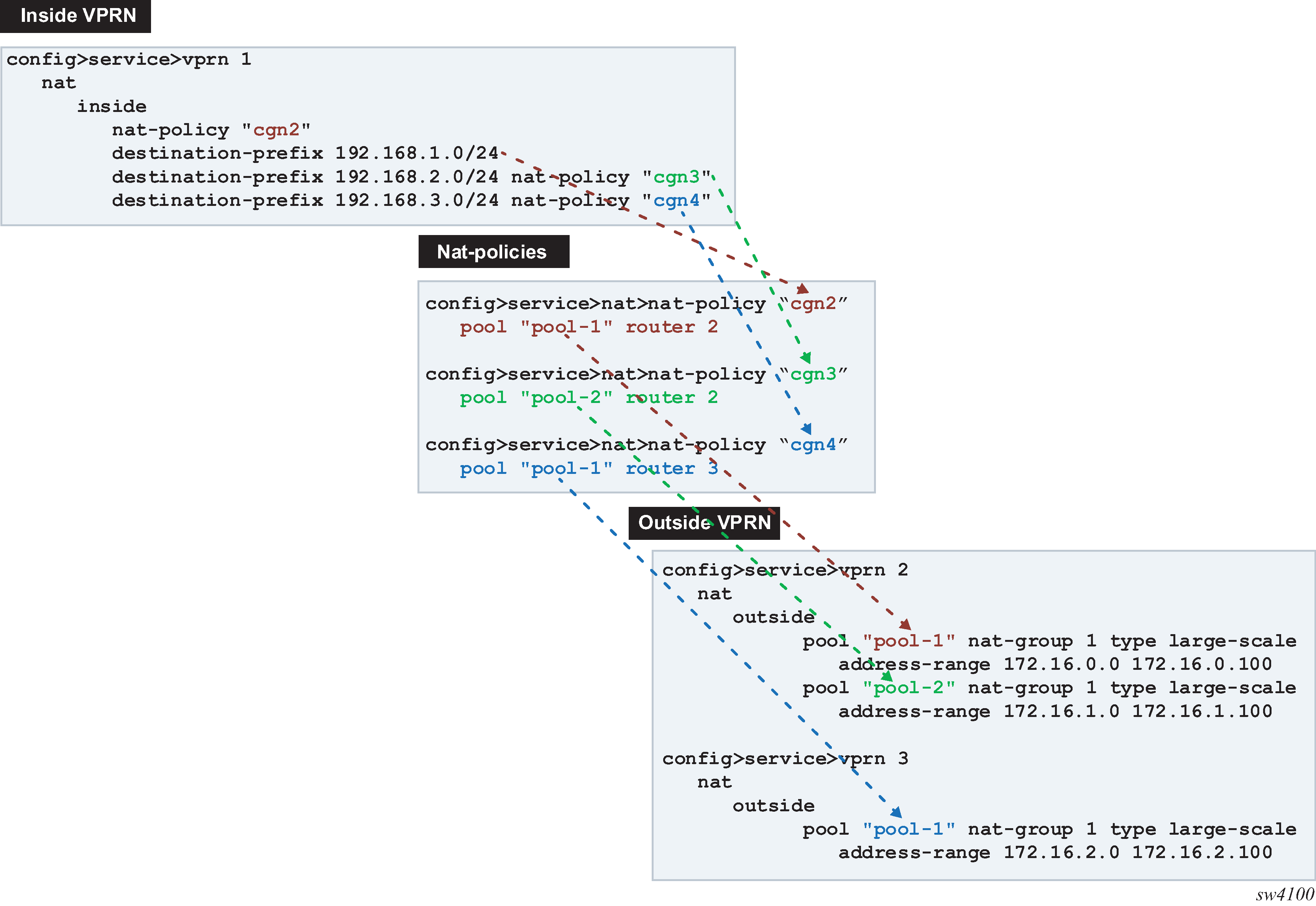
Logical representation of NAT routing through SR displays the logical configuration.

In the routing table, the ISA or VM-ESA next hops for NAT destination prefixes are shown as NAT inside semantics and the listed static routes belong to protocol NAT, as shown in the following example:
show router  1 route-table
===============================================================================
Route Table (Service: 1)
===============================================================================
Dest Prefix[Flags]                            Type    Proto     Age        Pref
      Next Hop[Interface Name]                                    Metric
-------------------------------------------------------------------------------
192.168.1.0/24                                Remote  NAT       05d15h21m  0
       NAT inside                                                   0
192.168.2.0/24                                Remote  NAT       05d15h21m  0
       NAT inside                                                   0
192.168.3.0/24                                Remote  NAT       05d15h21m  0
       NAT inside                                                   0
When forwarding in the downstream direction (in the public to private direction), the outside address ranges (NAT pool ranges 172.16.x.x, as shown in the following example) are subdivided (micronetted) and distributed on a more granular level across the ISAs and VM-ESAs in the same NAT group. The micronetting is necessary so that traffic can be distributed across ISAs or VM-ESAs. The micronets are visible in the routing table and their next hops point to the corresponding ISA or VM-ESA. Micronets are used to attract traffic toward the ISAs or VM-ESAs in the downstream direction. An example of the route table on the outside (public side) is shown in the following output:
show router 3 route-table
===============================================================================
Route Table (Router: Base)
===============================================================================
Dest Prefix[Flags]                            Type    Proto     Age        Pref
      Next Hop[Interface Name]                                    Metric
-------------------------------------------------------------------------------
172.16.2.0/28                                   Remote  NAT       05d15h32m  0
       NAT outside to mda 1/2                                       0
172.16.2.16/28                                   Remote  NAT       05d15h32m  0
       NAT outside to mda 2/2                                       0
172.16.2.32/28                                   Remote  NAT       05d15h32m  0
       NAT outside to mda 1/2                                       0
172.16.2.48/28                                   Remote  NAT       05d15h32m  0
       NAT outside to mda 2/2                                       0
172.16.2.64/28                                   Remote  NAT       05d15h32m  0
       NAT outside to mda 1/2                                       0
172.16.2.80/28                                   Remote  NAT       05d15h32m  0
       NAT outside to mda 2/2                                       0
172.16.2.96/31                                   Remote  NAT       05d15h32m  0
       NAT outside to mda 1/2                                       0
172.16.2.98/31                                   Remote  NAT       05d15h32m  0
       NAT outside to mda 2/2                                       0
172.16.2.100/32                                   Remote  NAT       05d15h32m  0
       NAT outside to mda 1/2                                       0
Dynamic routing to LSN44
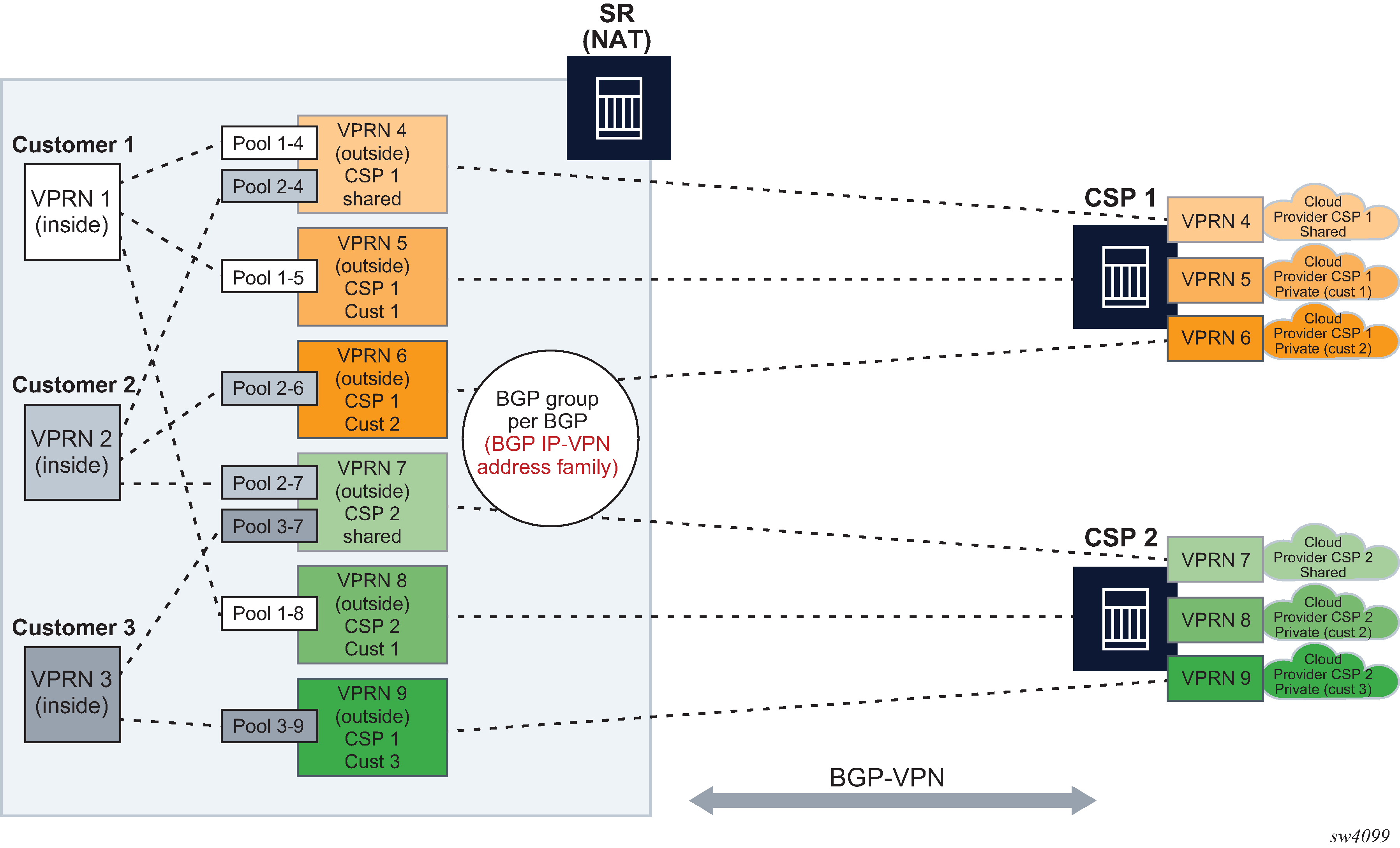
LSN44 steering on the inside routing context is supported through routes received from the BGP-VPN protocol. NAT-related BGP-VPN routes are received from BGP-VPN peers in the outside routing contexts and are imported in the inside routing context. This way, the routing information for NAT is dynamically updated without operator intervention. Typical users are operators using NAT who are peering with third parties and frequently re-purposing their IPv4 prefixes based on usage or redundancy. A cloud solution is an example of these types of peering partners.
A typical network design describing this scenario is shown in Connectivity diagram.
Dynamic import of BGP-VPN routes with the next-hop leading to NAT (ISA or VM-ESA) is performed through a routing policy where:
A route received on the outside by BGP-VPN is matched against the configured route target community and installed in the outside VPRN automatically. Alternatively, the route can be matched against any BGP-VPN supported criteria through an import route policy and installed in the outside routing table.
Within the NAT context on the inside, the BGP-VPN route is imported through an import route policy, where the route is matched against any BGP-VPN supported criteria. In the same route policy, the route is associated with a NAT policy which determines the NAT pool and outside routing context.
An example configuration for the route policy that is referenced as import within a NAT context is shown below.
MD-CLI
configure
    policy-options {
        policy-statement <policy-name> {
            entry <id> {
                from {
           :     <<any match condition supported for BGP-VPN routes
                }
               action {
                    action-type accept
                    nat-policy <nat-policy-name>
                }
            }
        }
    }
If the NAT policy under the action is omitted, then a default NAT policy from the inside routing context is used.
The configured route policy is then applied under NAT in the inside routing context.
MD-CLI
configure {
    service vprn <name>  }
        nat }
            inside }
                large-scale }
                    nat-policy <name>   <<default nat-policy
                        nat44 }
                        nat-import <name> }
               {
            {
        {
    {
Deterministic LSN44, non-deterministic LSN44, and 1:1 static LSN44 in a dynamic routing environment
Deterministic and non-deterministic LNS44 can be simultaneously configured in an inside routing context. See Multiple NAT policies and deterministic NAT for more details.
Combination of static and dynamic routes
If the same route is provided by the static configuration and dynamically by a BGP-VPN, only the configured (static) route is installed in the routing table. In other words, a static route has a higher priority than the dynamic route.
Scale and logging notes
A NAT route is not installed in the routing table on the inside if one of the following occurs:
A maximum number of NAT policies per inside VPRN is reached. A NAT policy indirectly represents the route’s next hop in the inside routing context (toward the ISA or VM-ESA).
The next hop in the outside routing context is not available.
A maximum number of imported NAT routes is reached. There is a maximum numbers of routes that can be imported into the inside routing context from each outside VPRN.
A maximum number of the dynamic NAT routes per system is reached.
NAT steering through IP filters
Traffic steering to NAT through IP filters is more customizable than steering through routing with traffic identification because of the extensive matching criteria offered by IP filters.
An IP filter can be applied on:
ingress access and network interfaces on the private side
network ingress of a VPRN, for example, auto-bind or spoke SDPs
ingress SLA profile in subscriber management
The filter entry used for NAT steering has an action nat which redirects traffic identified through matched criteria toward ISAs and VM-ESAs. The entries in the filter are evaluated the first match ends the filter evaluation.
MD-CLI
[pr:/configure filter]
    match-list {
        ip-prefix-list "nat-dest" {
            prefix 172.16.0.0/24 { }
        }
    }
    ip-filter "demo-filter" {
        default-action accept
        entry 10 {
            match {
                protocol udp
                src-port {
                    eq 30000
                }
            }
            action {
                accept
            }
        }
        entry 20 {
            match {
                protocol udp
                dst-ip {
                    ip-prefix-list "nat-dest"
                }
                src-port {
                    range {
                        start 40000
                        end 50000
                    }
                }
            }
            action {
                nat {
                }
            }
        }
        entry 30 {
            match {
                protocol udp
            }
            action {
                drop
            }
        }
    }
In this scenario, any UDP traffic with the source port 3000 as indicated in entry 10, is allowed through the system, bypassing NAT UDP traffic with source ports in the range 40,000 to 50,000 destined for network 172.16.0.0.24 as indicated in entry 20, is NAT’d. The remaining UDP traffic is dropped, according to entry 30.
The remaining non-UDP traffic is allowed through the filter and bypasses NAT as indicated by the default action accept.
The following is an example of a filter applied to a network interface on ingress.
MD-CLI
[pr:/configure]
 router "Base" {
        interface "annex" {
            port 1/x1/2/c10/1:1
            ingress {
                filter {
                    ip "demo-filter"
                }
            }
            ipv4 {
                primary {
                    address 192.168.12.2
                    prefix-length 24
                }
            }
        }
}
An example of a filter applied to all ingress network ingress for a specific VPRN.
MD-CLI
[pr:/configure service]
vprn "demo" {
        service-id 1
        customer "1"
        network {
            ingress {
                filter {
                    ip "demo-filter"
                }
            }
        }
}
An example of a filter applied on ingress in an SLA profile.
MD-CLI
[pr:/configure service]
subscriber-mgmt {
        sla-profile "demo" {
            ingress {
                ip-filter "demo-filter"
            }
        }
}
L2-Aware support for residential gateway types
L2-Aware NAT functionality is tightly coupled with ESM and therefore, the type of the residential gateway supported in L2-Aware NAT depends on the anti-spoof setting of the ESM subscriber. In this context, the residential gateway types can be:
bridged
Subscriber-hosts behind the residential gateway are individually set up in the BNG and their IP and MAC addresses are known to the BNG during the host setup phase (DHCP/PPPoE).
routed with NAT
The only residential gateway is set up in the BNG. The residential gateway IP and MAC address is known in the BNG during the set up phase. Subscriber hosts behind the residential gateway are not known in the BNG, but instead, they are hidden behind the residential gateway’s NAT.
routed without NAT
The residential gateway is set up in the BNG. Hosts behind residential gateway’s NAT are not set up in the BNG. The control plane in the BNG is not aware of their IP and MAC addresses. To forward data traffic from these routed hosts in the upstream direction, the anti-spoof in BNG must be set to nh-mac. In the downstream direction, a frame route pointing to the residential gateway must be present in the BNG.
Note that DHCP relay on the residential gateway is disabled. If it was enabled, then routed hosts could be set up in BNG with lease-populate [nbr-of-leases] l2-header [mac ieee-address] command under the group interface.
Anti-spoof settings in ESM that are relevant to this context include:
mac-ip
Anti-spoof is based on the MAC address and the source IP address of the host. This anti-spoof type is more stringent and secure.
nh-mac
Anti-spoof is based only on the MAC address of the host. This is used in the presence of IP hosts behind the routed RG without NAT. The IP addresses of these hosts are exposed within the data traffic received by BNG, even though those hosts were never explicitly set up in the BNG (using DHCP/PPP). Nh-mac anti-spoof ensures that data traffic from unknown (unknown on the control plane level) IP addresses pass through BNG in the upstream direction. These hosts are behind a known subscriber host, that is, in this case, a routed residential gateway without NAT.
In addition to the anti-spoof setting, an additional CLI command is required in BNG to select the needed residential gateway type:
configure subscr-mgmt sub-prof nat-access-mode {auto | bridged}
The relationship between the anti-spoof setting in ESM, nat-access-mode CLI flag and a compatible residential gateway model is shown in Anti-spoof setting comparisons .
| Model no. | Home model | Anti-spoof | NAT access mode CLI flag | Supported in SR OS | Comments |
|---|---|---|---|---|---|
1 |
Bridged RG |
mac-ip |
auto bridged |
Yes |
All bridged subscriber hosts are eligible for L2-Aware NAT with the most stringent anti-spoof settings. If there is only one host behind the bridged RG, then this model becomes the same as model 3. |
2 |
Bridged RG |
nh-mac |
bridged |
Yes |
All bridged subscriber hosts are eligible for L2-Aware NAT. In this model, MAC addresses within the subscriber and SAP must be unique. Even though the anti-spoof in ESM is set to nh-mac, the NAT function still checks the source IP address of the upstream traffic and drops any traffic from spoofed IP addresses (IP source address that do not belong to the bridged hosts, as initially setup in ESM). |
3 |
Routed RG with NAT |
mac-ip |
auto bridged |
Yes |
Subscriber hosts behind the residential gateway are hidden behind routed RG’s NAT and are not visible in BNG. |
4 |
Routed RG with NAT |
nh-mac |
auto bridged |
Yes |
This combination is supported but with inferior anti-spoofing. |
5 |
Routed RG, no NAT |
mac-ip |
— |
No |
This combination is not supported. The mac-ip anti-spoof in ESM blocks traffic for the host with an exposed source IP address that resides behind the RG. Those hosts are not set up in the BNG on the control plane level (DHCP/PPPoE is not sent from those hosts). |
6 |
Routed RG, no NAT |
nh-mac |
auto bridged |
Yes |
Subscriber hosts with exposed source IP addresses pass the nh-mac anti-spoof check and are eligible for L2-Aware NAT. |
One-to-one (1:1) NAT
In 1:1 NAT, each source IP address is translated in 1:1 fashion to a corresponding outside IP address. However, the source ports are passed transparently without translation.
The mapping between the inside IP addresses and outside IP addresses in 1:1 NAT supports two modes:
dynamic
The operator can specify the outside IP addresses in the pool, but the exact mapping between the inside IP address and the configured outside IP addresses is performed dynamically by the system in a semi-random fashion.
static
The mappings between IP addresses are configurable and they can be explicitly set.
The dynamic version of 1:1 NAT is protocol dependent. Only TCP/UDP/ICMP protocols are allowed to traverse such NAT. All other protocols are discarded, with the exception of PPTP with ALG. In this case, only GRE traffic associated with PPTP is allowed through dynamic 1:1 NAT.
The static version of 1:1 NAT is protocol agnostic. This means that all IP based protocols are allowed to traverse static 1:1 NAT.
The following points are applicable to 1:1 NAT:
Even though source ports are not being translated, the state maintenance for TCP and UDP traffic is still performed.
Traffic can be initiated from outside toward any statically mapped IPv4 address.
1:1 NAT can be supported simultaneously with NAPT (classic non 1:1 NAT) within the same inside routing context. This is accomplished by configuring two separate NAT pools, one for 1:1 NAT and the other for non 1:1 NAPT.
Static 1:1 NAT
In static 1:1 NAT, inside IP addresses are statically mapped to the outside IP addresses. This way, devices on the outside can predictably initiate traffic to the devices on the inside.
Static configuration is based on the CLI concepts used in deterministic NAT. For example:
config
   router
      nat
         inside
             deterministic
               prefix 10.0.0.0/24 subscriber-type classic-lsn-sub nat-policy ‛one-to-one’
            map start 10.0.0.10       end 10.0.0.10    to 1.2.3.4
                     map start 10.0.0.15       end 10.0.0.15    to 1.2.3.20
                     map start 10.0.0.100    end 10.0.0.100 to 1.2.3.30
Static mappings are configured according to the map statements. In classic CLI, the map statement can be configured manually by the operator or automatically by the system. In MD-CLI, the map statement must be configured by the operator, but the tools perform nat deterministic calculate-maps command can be used to produce system-generated maps. The calculate-maps command outputs a set of system-generated map statements. The map parameters can then be copied and pasted into an MD-CLI candidate configuration by the operator.
IP addresses from the automatically-generated map statements are sequentially mapped into available outside IP addresses in the pool:
The first inside IP address is mapped to the first available outside IP address from the pool.
The second inside IP address is mapped to the second available outside IP address from the pool.
The following mappings apply to the example above:
Static mappings
   10.0.0.0 — 1.2.3.0
   10.0.0.1 — 1.2.3.1
   10.0.0.2  —  1.2.3.2
   10.0.0.3  —  1.2.3.3
   10.0.0.4  —  1.2.3.5
   10.0.0.5  —  1.2.3.6
   :
   10.0.0.9  —  1.2.3.10
   10.0.0.10  —  1.2.3.4
   10.0.0.11  —  1.2.3.11
   10.0.0.12  —  1.2.3.12
   :
   10.0.0.14  —  1.2.3.14
   10.0.0.15  —  1.2.3.20
   10.0.0.16  —  1.2.3.15
   :
   10.0.0.19  —  1.2.3.18
   10.0.0.20  —  1.2.3.19
   10.0.0.21  —  1.2.3.21
   :
   10.0.0.28  —  1.2.3.28
   10.0.0.29  —  1.2.3.29
   10.0.0.30  —  1.2.3.31
   :
   10.0.0.99  —  1.2.3.100
   10.0.0.100 — 1.2.3.30
   10.0.0.101  —  1.2.3.101
   :
   10.0.0.255  —  1.2.3.255
Protocol agnostic behavior
Although static 1:1 NAT is protocol agnostic, the state maintenance for TCP and UDP traffic is still required to support ALGs. Therefore, the existing scaling limits related to the number of supported flows still apply.
Protocol agnostic behavior in 1:1 NAT is a property of a NAT pool:
config
   router / service vprn
      nat
            outside
               pool ‟one-to-one” nat-group 1 type large-scale applications agnostic create
                  address-range 192.168.0.0 192.168.0.10 create
The application agnostic command is a pool create-time parameter. This command automatically pre-sets the following pool parameters:
mode one-to-one
port-forwarding-range 0
port-reservation blocks 1
subscriber-limit 1
deterministic port-reservation 65536.
When pre-set, these parameters cannot be changed while the pool is operating in protocol agnostic mode.
The deterministic port-reservation 65536 command configures the pool to operate in static (or deterministic) mode.
Modification of parameters in static 1:1 NAT
Parameters in the static 1:1 NAT can be changed according to the following rules:
The deterministic pool must be in a no shutdown state when a prefix or a map command in deterministic NAT is added or removed.
All configured prefixes referencing the pool via the NAT policy must be deleted (unconfigured) before the pool can be shut down.
Map statements can be modified only when prefix is shutdown state. All existing map statements must be removed before the new ones are created.
Load distribution over ISAs in static 1:1 NAT
For best traffic distribution over ISAs, the value of the classic-lsn-max-subscriber-limit max parameter should be set to 1.
config
   router / service vprn X
      nat
         inside
             deterministic
               classic-lsn-max-subscriber-limit  <num>
This mean that traffic is load balanced over ISAs based on inside IP addresses. In static 1:1 NAT this is certainly possible because the subscriber-limit parameter at the pool level is preset to a fixed value of 1.
However, if 1:1 static NAT is simultaneously used with regular (many-to-one) deterministic NAT where the subscriber-limit parameter can be set to a value greater than 1, then the classic-lsn-max-subscriber-limit parameter also has to be set to a value that is greater than 1. The consequence of this is that the traffic is load balanced based on the consecutive blocks of IP addresses (subnets) instead of individual IP addresses. See Deterministic NAT for information about Deterministic NAT behavior.
NAT-policy selection
The traffic match criteria used in the selection of specific NAT policies in static 1:1 NAT (the deterministic part of the configuration) must not overlap with traffic match criteria that is used in the selection of a specific NAT policy used in filters or in destination-prefix statement (these are used for traffic diversion to NAT). Otherwise, traffic is dropped in ISA.
A specific NAT policy in this context refers to a non-default NAT policy, or a NAT policy that is directly referenced in a filter, in a destination-prefix command or in a deterministic prefix command.
The following example is used to clarify this point:
Traffic is diverted to NAT using specific nat-policy pol-2:
service vprn 10 nat inside destination-prefix 192.168.0.0/16 nat-policy pol-2 deterministic prefix 10.10.10.0/24 subscriber-type classic-lsn-sub nat-policy pol-1-
The deterministic (source) prefix 10.10.10.0/30 is configured to be mapped to nat-policy pol-1 specifically which points to protocol agnostic 1:1 nat pool.
service vprn 10 nat inside destination-prefix 192.168.0.0/16 nat-policy pol-2 deterministic prefix 10.10.10.0/30 subscriber-type classic-lsn-sub nat-policy pol-1 -
Packet received in the ISA has srcIP 10.10.10.1 and destIP 192.168.10.10.
-
If no NAT mapping for this traffic exists in the ISA, a NAT policy (and with this, the NAT pool) must be determined to create the mapping. Traffic is diverted to NAT using nat-policy pol-2, while the deterministic mapping suggests that nat-policy pol-1 should be used (this is a different pool from the one referenced in nat-policy pol-2). Because of the specific NAT policy conflict, traffic is dropped in the ISA.
To successfully pass traffic between two subnets through NAT while simultaneously using static 1:1 NAT and regular LSN44, a default (non-specific) NAT policy can be used for regular LSN44.
For example:
service vprn 10
   nat
      inside
         destination-prefix 192.168.0.0/16
            nat-policy pol-2
               deterministic
                  prefix 10.10.10.0/30 subscriber-type classic-lsn-sub nat-policy pol-1
In this case, the four hosts from the prefix 10.10.10.0/30 are mapped in 1:1 fashion to 4 IP addresses from the pool referenced in the specific nat-policy pol-1, while all other hosts from the 10.10.10.0/24 network are mapped to the NAPT pool referenced by the default nat-policy pol-2. In way, a NAT policy conflict is avoided.
In summary, a specific NAT policy (in filter, destination-prefix command or in deterministic prefix command) always takes precedence over a default NAT policy. However, traffic that matches classification criteria (in filter, destination-prefix command or a deterministic prefix command) that leads to multiple specific nat-policies, is dropped.
Mapping timeout
Static 1:1 NAT mappings are explicitly configured, and therefore, their lifetime is tied to the configuration.
Logging
The logging mechanism for static mapping is the same as in Deterministic NAT. Configuration changes are logged via syslog and enhanced with reverse querying on the system.
Restrictions
Static 1:1 NAT is supported only for LSN44 (there is no support for DS-Lite/NAT64 or L2-Aware NAT).
ICMP
In 1:1 NAT, specific ICMP messages contain an additional IP header embedded in the ICMP header. For example, when the ICMP message is sent to the source because of the inability to deliver datagram to its destination, the ICMP generating node includes the original IP header of the packet plus 64bits of the original datagram. This information helps the source node to match the ICMP message to the process associated with this message.
When these messages are received in the downstream direction (on the outside), 1:1 NAT recognizes them and changes the destination IP address not only in the outside header but also in the ICMP header. In other words, a lookup in the downstream direction is performed in the ISA to determine if the packet is ICMP with a specific type. Depending on the outcome, the destination IP address in the ICMP header is changed (reverted to the original source IP address).
Messages carrying the original IP header within ICMP header are:
Destination Unreachable Messages (Type 3)
Time Exceeded Message (Type 11)
Parameter Problem Message (Type 12)
Source Quench Message (Type 4)
Deterministic NAT
Overview
In deterministic NAT the subscriber is deterministically mapped into an outside IP address and a port block. The algorithm that performs this deterministic mapping is revertive, which means that a NAT subscriber can be uniformly derived from the outside IP address and the outside port (and the routing instance). Thus, logging in deterministic NAT is not needed.
The deterministic [subscriber <-> outside-ip, deterministic-port-block] mapping can be automatically extended by a dynamic port-block in case that deterministic port block becomes exhausted of ports. By extending the original deterministic port block of the NAT subscriber by a dynamic port block yields a satisfactory compromise between a deterministic NAT and a non-deterministic NAT. There is no logging as long as the translations are in the domain of the deterministic NAT. After the dynamic port block is allocated for port extension, logging is automatically activated.
NAT subscribers in deterministic NAT are not assigned outside IP address and deterministic port-block on a first come first serve basis. Instead, deterministic mappings are pre-created at the time of configuration regardless of whether the NAT subscriber is active or not. In other words we can say that overbooking of the outside address pool is not supported in deterministic NAT. Consequently, all configured deterministic subscribers (for example, inside IP addresses in LSN44 or IPv6 address/prefix in DS-Lite) are guaranteed access to NAT resources.
Supported deterministic NAT types
The routers support Deterministic LSN44 and Deterministic DS-Lite. The basic deterministic NAT principle is applied equally to both NAT flavors. The difference between the two stem from the difference in interpretation of the subscriber – in LSN44 a subscriber is an IPv4 address, whereas in DS-Lite the subscriber is an IPv6 address or prefix (configuration dependent).
With the exception of classic-lsn-max-subscriber-limit and dslite-max-subscriber-limit commands in the inside routing context, the deterministic NAT configuration blocks are for the most part common to LSN44 and DS-Lite.
Deterministic DS-Lite section at the end of this section focuses on the features specific to DS-Lite.
Number of subscribers per outside IP and per pool
The outside pools in deterministic NAT can contain an arbitrary number of address ranges, where each address range can contain an arbitrary number of IP addresses (up to the ISA maximum).
The maximum number of NAT subscribers that can be mapped to a single outside IP address is configurable using a subscriber-limit command under the pool hierarchy. For Deterministic NAT, this number is restricted to the power of 2 (2^n). The consequence of this is that the number of NAT subscribers must be configuration-wise organized in ranges with the boundary that must be power of 2.
For example, in LSN44 where the NAT subscriber is an IP address, the deterministic subscribers would be configured with prefixes (for example, 10.10.10.0/24 – 256 subscribers) instead of an IP address range that would contain an arbitrary number of addresses (for example, 10.10.10.10 – 10.10.10.50).
On the other hand, in DS-Lite the deterministic subscribers are for the most part already determined by the prefix with the subscriber-prefix-length command under the DS-Lite configuration node.
The number of subscribers per outside IP (the subscriber-limit command [2^n]) multiplied by the number of IP addresses over all address-range in an outside pool determines the maximum number of subscribers that a deterministic pool can support.
Referencing a pool
In deterministic NAT, the outside pool can be shared amongst subscribers from multiple routing instances. Also, NAT subscribers from a single routing instance can be selectively mapped to different outside pools.
Outside pool configuration
The number of deterministic mappings that a single outside IP address can sustain is determined through the configuration of the outside pool.
The port allocation per an outside IP is shown in Outside pool configuration.

The well-known ports are predetermined and are in the range 0 — 1023.
The upper limit of the port range for static port forwards (wildcard range) is determined by the existing port-forwarding-range command.
The range of ports allocated for deterministic mappings (DetP) is determined by multiplying the number of subscribers per outside IP (subscriber-limit command) with the number of ports per deterministic block (deterministic>port-reservation command). The number of subscribers per outside IP in deterministic NAT must be power of 2 (2^n).
The remaining ports, extending from the end of the deterministic port range to the end of the total port range (65,535) are used for dynamic port allocation. The size of each dynamic port block is determined with the existing port-reservation command.
The determinisitic>port-reservation command enables deterministic mode of operation for the pool.
Examples:
Three examples follow, with deterministic Large Scale NAT44, where the requirements are:
300, 500 or 700 (three separate examples) ports are in each deterministic port block.
A subscriber (an inside IPv4 address in LSN44) can extend its deterministic ports by a minimum of one dynamic port-block and by a maximum of four dynamic port blocks.
Each dynamic port-block contains 100 ports.
Oversubscription of dynamic port blocks is 4:1. This means that 1/4th of inside IP addresses may be starved out of dynamic port blocks in worst case scenario.
The wildcard (static) port range is 3000 ports.
In the first case, the ideal case is examined where an arbitrary number of subscribers per outside IP address is allocated according to our requirements described above. Then the limitation of the number of subscribers being power of 2 is factored in.
| Well-known ports1 | Static port range1 | Number of ports in deterministic block1 | Number of deterministic blocks | Number of ports in dynamic block1 | Number of dynamic blocks1 | Number of inside IP addresses per outside IP address1 | Block limit per inside IP address1 | Wasted ports |
|---|---|---|---|---|---|---|---|---|
0-1023 |
1024-4023 |
300 |
153 |
100 |
153 |
153 |
5 |
312 |
0-1023 |
1024-4023 |
500 |
102 |
100 |
102 |
102 |
5 |
312 |
0-1023 |
1024-4023 |
700 |
76 |
100 |
76 |
76 |
5 |
712 |
The example in Contiguous number of subscribers shows how port ranges would be carved out in ideal scenario.
The other values are calculated according to the fixed requirements.
port-block-limit includes the deterministic port block plus all dynamic port-blocks.
Next, in Preserving Det/Dyn port ratio with 2^n subscribers, a more realistic example with the number of subscribers being equal to 2^n are considered. The ratio between the deterministic ports and the dynamic ports per port-block just like in the example above: 3/1, 5/1 and 7/1 are preserved. In this case, the number of ports per port-block is dictated by the number of subscribers per outside IP address.
| Well-known ports1 | Static port range1 | Number of ports in deterministic block1 | Number of deterministic blocks | Number of ports in dynamic block1 | Number of dynamic blocks | Number of inside IP addresses per outside IP address1 | Block limit per inside IP address1 | Wasted ports |
|---|---|---|---|---|---|---|---|---|
0-1023 |
1024-4023 |
180 |
256 |
60 |
256 |
256 |
5 |
72 |
0-1023 |
1024-4023 |
400 |
128 |
80 |
128 |
128 |
5 |
72 |
0-1023 |
1024-4023 |
840 |
64 |
120 |
64 |
64 |
5 |
72 |
The final example (Fixed number of deterministic ports with 2^n subscribers) is similar as Contiguous number of subscribers with the difference that the number of deterministic port blocks fixed are kept, as in the original example (300, 500 and 700).
| Well-known ports | Static port range | Number of ports in deterministic block | Number of deterministic blocks | Number of ports in dynamic block | Number of dynamic blocks | Number of inside IP addresses per outside IP address | Block limit per inside IP address | Wasted ports |
|---|---|---|---|---|---|---|---|---|
0-1023 |
1024-4023 |
300 |
128 |
180 |
128 |
128 |
5 |
72 |
0-1023 |
1024-4023 |
500 |
64 |
461 |
64 |
64 |
5 |
8 |
0-1023 |
1024-4023 |
700 |
64 |
261 |
64 |
64 |
5 |
8 |
The three examples from above should give us a perspective on the size of deterministic and dynamic port blocks in relation to the number of subscribers (2^n) per outside IP address. Operators should run a similar dimensioning exercise before they start configuring their deterministic NAT.
The CLI for the highlighted case in the Contiguous number of subscribers is displayed:
configure
   service
      vprn
         nat
            outside
               pool mypool
                  port-reservation ports 180
                  deterministic
      port-reservation 300
                  subscriber-limit 128
                  port-forwarding-range 4023
Where:
128 subs * 300ports = 38,400 deterministic port range
128 subs * 180ports = 23,040 dynamic port range
Det+dyn available ports = 65,536 – 4024 = 61,512
Det+dyn usable pots = 128*300 + 128 *180 = 61,440 ports
72 ports per outside-ip are wasted.
configure
service
nat
nat-policy mypolicy
block-limit 5 1 deterministic port block + 4 dynamic port blocks
This configuration allows 128 subscribers (inside IP addresses in LSN44) for each outside address (compression ratio is 128:1) with each subscriber being assigned up to 1020 ports (300 deterministic and 720 dynamic ports over 4 dynamic port blocks).
The outside IP addresses in the pool and their corresponding port ranges are organized as shown in Outside address ranges.
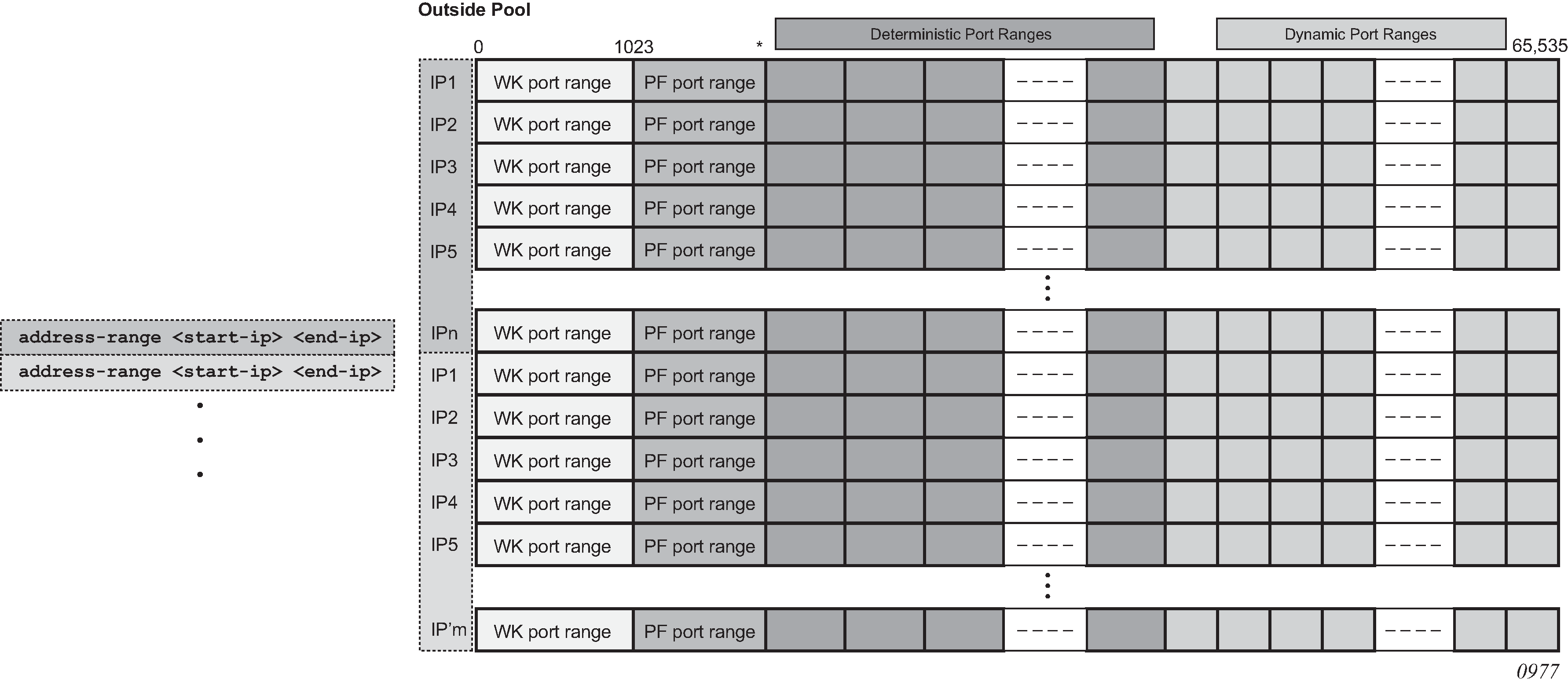
Assuming that the above graph depicts an outside deterministic pool, the number of subscribers that can be accommodated by this deterministic pool is represented by purple squares (number of IP addresses in an outside pool * subscriber-limit). The number of subscribers across all configured prefixes on the inside that are mapped to the same deterministic pool must be less than the outside pool can accommodate. In other words, an outside address pool in deterministic NAT cannot be oversubscribed.
The following is a CLI representation of a deterministic pool definition including the outside IP ranges:
pool ‛mypool’ nat-group 1 type large-scale
      port-reservation {blocks <dynBlocks>} | {ports <ports>}
      deterministic
            port-reservation <ports>
      subscriber-limit <sub-limit>
      port-forwarding-range <pfRange>
      address-range <start-ip-address> <end-ip-address>
      address-range <start-ip-address> <end-ip-address>
Mapping rules and the map command in deterministic LSN44
The common building block on the inside in the deterministic LSN44 configuration is a IPv4 prefix. The NAT subscribers (inside IPv4 addresses) from the configured prefix are deterministically mapped to the outside IP addresses and corresponding deterministic port-blocks. Any inside prefix in any routing instance can be mapped to any pool in any routing instance (including the one in which the inside prefix is defined).
The mapping between the inside prefix and the deterministic pool is achieved through a NAT policy that can be referenced per each individual inside IPv4 prefix. IPv4 addresses from the prefixes on the inside are distributed over the IP addresses defined in the outside pool referenced by the NAT policy.
The mapping itself is represented by the map command under the prefix hierarchy:
router/service vprn
   nat
      inside
         deterministic
             prefix <ip-prefix/length> subscriber-type <nat-sub-type> nat-policy <nat-policy-name>
               map start <inside-ip-address> end <inside-ip-address> to <outside-ip-address>
The purpose of the map statement is to split the number of subscribers within the configured prefix over available sequences of outside IP addresses. The key parameter that governs mappings between the inside IPv4 addresses and outside IPv4 addresses in deterministic LSN44 is defined by the outside>pool>subscriber-limit command. This parameter must be power of 2 and it limits the maximum number of NAT subscribers that can be mapped to the same outside IP address.
The follow are rules governing the configuration of the map statement:
In case that the number of subscribers (IP addresses in LSN44) in the map statement is larger than the subscriber-limit per outside IP, then the subscribers must be split over a block of consecutive outside IP addresses where the outside-ip-address in the map statement represent only the first outside IP address in that block.
The number of subscribers (range of inside IP addresses in LSN44) in the map statement does not have to be a power of 2. Rather it has to be a multiple of a power of two m * 2^n, where m is the number of consecutive outside IP addresses to which the subscribers are mapped and the 2^n is the subscriber-limit per outside IP.
An example of the map statement is shown below:
router
nat
      outside
         pool ‛my-det-pool’ nat-group 1 type large-scale
            subscriber-limit 128
               deterministic
                   port-reservation 400
            address-range 192.168.0.0 192.168.0.10

service vprn 10
nat
      inside
         deterministic
             prefix 10.0.0.0/24 subscriber-type classic-lsn-sub nat-policy det
               map start 10.0.0.0 end 10.0.0.255 to 192.168.0.1
In this case, the configured 10.0.0.0/24 prefix is represented by the range of IP addresses in the map statement (10.0.0.0-10.0.0.255). Because the range of 256 IP addresses in the map statement cannot be mapped into a single outside IP address (subscriber-limit=128), this range must be further implicitly split within the system and mapped into multiple outside IP addresses. The implicit split creates two IP address ranges, each with 128 IP addresses (10.0.0.0/25 and 10.0.0.128/25) so that addresses from each IP range are mapped to one outside IP address. The hosts from the range 10.0.0.0-10.0.0.127 are mapped to the first IP address in the pool (128.251.0.1) as explicitly stated in the map statement (to statement). The hosts from the second range, 10.0.0.128-10.0.0.255 are implicitly mapped to the next consecutive IP address (128.251.0.2).
Alternatively, the map statement can be configured as:
service vprn 10
nat
      inside
         deterministic
             prefix 10.0.0.0/24 subscriber-type classic-lsn-sub nat-policy det
               map start 10.0.0.0 end 10.0.0.127 to 192.168.0.1
               map start 10.0.0.128 end 10.0.0.255 to 192.168.0.5
In this case the IP address range in the map statement is split into two non-consecutive outside IP addresses. This gives the operator more freedom in configuring the mappings.
However, the following configuration is not supported:
service vprn 10
nat
      inside
         deterministic
             prefix 10.0.0.0/24 subscriber-type classic-lsn-sub nat-policy det
               map start 10.0.0.0 end 10.0.0.63 to 192.168.0.1
               map start 10.0.0.64 end 10.0.0.127 to 192.168.0.3
               map start 10.0.0.128 end 10.0.0.255 to 192.168.0.5
Considering that the subscriber-limit = 128 (2^n; where n=7), the lower n bits of the start address in the second map statement (map start 10.0.0.64 end 10.0.0.127 to 192.168.0.3) are not 0. This is in violation of the rule #1 that governs the provisioning of the map statement.
Assuming that we use the same pool with 128 subscribers per outside IP address, the following scenario is also not supported (configured prefix in this example is different than in previous example):
service vprn 10
nat
      inside
         deterministic

prefix 10.0.0.0/26 subscriber-type classic-lsn-sub nat-policy det
               map start 10.0.0.0 end 10.0.0.63 to 192.168.0.1

prefix 10.0.1.0/26 subscriber-type classic-lsn-sub nat-policy det
               map start 10.0.1.0 end 10.0.1.63 to 192.168.0.1
Although the lower n bits in both map statements are 0, both statements are referencing the same outside IP (192.168.0.1). This is violating rule #2 that governs the provisioning of the map statement. Each of the prefixes in this case have to be mapped to a different outside IP address, which leads to underutilization of outside IP addresses (half of the deterministic port-blocks in each of the two outside IP addresses are not used).
In conclusion, considering that the number of subscribers per outside IP (subscriber-limit) must be 2^n, the inside IP addresses from the configured prefix is split on the 2^n boundary so that every deterministic port-block of an outside IP is used. In case that the originally configured prefix contains less subscribers (IP addresses in LSN44) than an outside IP address can accommodate (2^n), all subscribers from such configured prefix are mapped to a single outside IP. Because the outside IP cannot be shared with NAT subscribers from other prefixes, some of the deterministic port-blocks for this particular outside IP address are not used.
Each configured prefix can evaluate into multiple map commands. The number of map commands depends on the length of the configured prefix, the subscriber-limit command and fragmentation of outside address-range within the pool with which the prefix is associated.
In classic CLI, the map statement can be configured manually by the operator or automatically by the system. In MD-CLI, the map statement must be configured by the operator, but the tools perform nat deterministic calculate-maps command can be used to produce system-generated maps if needed. The calculate-maps command outputs a set of system-generated map statements. The map parameters can then be copied and pasted into an MD-CLI candidate configuration by the operator.
-
If the number of subscribers per configured prefix is greater than the subscriber-limit per outside IP parameter (2^n), then the lowest n bits of the map start inside-ip-address must be set to 0.
-
If the number of subscribers per configured prefix is equal or less than the subscriber-limit per outside IP parameter (2^n), then only one map command for this prefix is allowed. In this case there is no restriction on the lower n bits of the map start inside-ip-address. The range of the inside IP addresses in such map statement represents the prefix itself.
-
The outside-ip-address in the map statements must be unique amongst all map statements referencing the same pool. In other words, two map statements cannot reference the same outside-ip-address in the pool.
Hashing considerations in deterministic LSN44
Support for multiple MS-ISAs in the nat-group calls for traffic hashing on the inside in the ingress direction. This ensures fair load balancing of the traffic amongst multiple MS-ISAs. While hashing in non-deterministic LSN44 can be performed per source IP address, hashing in deterministic LSN44 is based on subnets instead of individual IP addresses. The length of the hashing subnet is common for all configured prefixes within an inside routing instance. In case that a prefixes from an inside routing instances is referencing multiple pools, the common hashing prefix length is chosen according to the pool with the highest number of subscribers per outside IP address. This ensures that subscribers mapped to the same outside IP address are always hashed to the same MS-ISA.
In general, load distribution based on hashing is dependent on the sample. Large and more diverse sample ensures better load balancing. Therefore the efficiency of load distribution between the MS-ISAs is dependent on the number and diversity of subnets that hashing algorithm is taking into consideration within the inside routing context.
A simple rule for good load balancing is to configure a large number of subscribers relative to the largest t subscriber-limit parameter in any pool that is referenced from this inside routing instance.

The configuration example shown Deterministic LSN44 configuration example depicts a case in which prefixes from multiple routing instances are mapped to the same outside pool and at the same time the prefixes from a single inside routing instance are mapped to different pools (we do not support the latter with non-deterministic NAT).
Distribution of outside IP addresses across MS-ISAs in an MS-ISA NA group
Distribution of outside IP addresses across the MS-ISAs is dependent on the ingress hashing algorithm. Because traffic from the same subscriber is always pre-hashed to the same MS-ISA, the corresponding outside IP address also must reside on the same ISA. CPM runs the hashing algorithm in advance to determine on which MS-ISA the traffic from particular inside subnet lands and then the corresponding outside IP address (according to deterministic NAT mapping algorithm) is configured in that particular MS-ISA.
Sharing of deterministic NAT pools
Sharing of the deterministic pools between LSN44 and DS-Lite is supported.
Simultaneous support of dynamic and deterministic NAT
Simultaneous support for deterministic and non-deterministic NAT inside of the same routing instance is supported. However, an outside pool can be only deterministic (although expandable by dynamic ports blocks) or non-deterministic at any time.
Ingress hashing for all NAT’d traffic within the VRF, in this case, is performed based on the subnets driven by the classic-lsn-max-subscriber-limit parameter.
Selecting traffic for NAT
Deterministic NAT does not change the way how traffic is selected for the NAT function but instead only defines a predictable way for translating subscribers into outside IP addresses and port-blocks.
Traffic is still diverted to NAT using the existing methods:
routing based
Traffic is forwarded to the NAT function if it matches a configured destination prefix that is part of the routing table. In this case inside and outside routing context must be separated.
filter based
Traffic is forwarded to the NAT function based on any criteria that can be defined inside an IP filter. In this case the inside and outside routing context can be the same.
Inverse mappings
The inverse mapping can be performed with a MIB locally on the node or externally via a script sourced in the router. In both cases, the input parameters are <outside routing instance, outside IP, outside port. The output from the mapping is the subscriber and the inside routing context in which the subscriber resides.
MIB approach
Reverse mapping information can be obtained using the following command:
tools dump nat deterministic-mapping outside-ip <ipv4-address> router <router-instance> outside-port <[1..65535]>
 <ipv4-address>       : a.b.c.d
 <router-instance>    : <router-name> | <service-id>
                        router-name    - "Base"
                        service-id     - [1..2147483647]
Example:
tools dump nat deterministic-mapping outside-ip 10.0.0.2 router "Base" outside-port 2333
Output:
Inside router 10 ip 10.0.5.171 -- outside router Base ip 10.0.0.2 port 2333 at Mon Jan 7 10:02:02 PST 2013
Off-line approach to obtain deterministic mappings
Instead of querying the system directly, there is an option where a Python script can be generated on router and exported to an external node. This Python script contains mapping logic for the configured deterministic NAT in the router. The script can be then queried off-line to obtain mappings in either direction. The external node must have installed Python scripting language with the following modules: getopt, math, os, socket and sys.
The purpose of such off-line approach is to provide fast queries without accessing the router. Exporting the Python script for reverse querying is a manual operation that needs to be repeated every time there is configuration change in deterministic NAT.
The script is exported outside of the box to a remote location (assuming that writing permissions on the external node are correctly set). The remote location is specified with the following command:
config service nat deterministic-script location <remote-url>
<remote-url>     - [{ftp:// | tftp://}<login>:<pswd>@<remote-locn>/][<file-path>]
180 chars max
The status of the script is shown using the following command:
show service nat deterministic-script
========================================================================
Deterministic NAT script data
========================================================================
Location            : ftp://10.10.10.10/pub/det-nat-script/det-nat.py
Save needed         : yes
Last save result    : none
Last save time      : N/A
========================================================================
After the script location is specified, the script can be exported to that location with the following command:
admin nat save-deterministic-script
This needs to be repeated manually every time the configuration affecting deterministic NAT changes.
Once the script is exported (saved), the status of the script is changed as well:
show service  nat deterministic-script
========================================================================
Deterministic NAT script data
========================================================================
Location            : ftp://10.10.10.10/pub/det-nat-script/det-nat.py
Save needed         : no
Last save result    : success
Last save time      : 2013/01/07 10:33:43
========================================================================
The script itself can be run to obtain mapping in forward or backward direction:
user@external-server:/home/ftp/pub/det-nat-script$ ./det-nat.py
Usage: det-nat-.py {{DIRECTION PARAMS} | -h[elp] }
where  DIRECTION := { -f[orward] | -b[ackward] }
where  PARAMS := { -s[ervice] -a[ddress] -p[ort] }
The following displays an example in which source addresses are mapped in the following manner:
Router 10, Source-ip:  10.0.5.0-10.0.5.127      to router base, outside-ip  10.0.0.1
Router 10 Source-ip: 10.0.5.128-10.0.5.255    to router base outside-ip 10.0.0.2
The forward query for this example is performed as:
user@external-server:/home/ftp/pub/det-nat-script$ ./det-nat.py -f -s 10 -a 10.0.5.10
Output:
subscriber has public ip address 10.0.0.1 from service 0 and is using ports [1324 - 1353]
The reverse query for this example is performed as:
user@external-server:/home/ftp/pub/det-nat-script$ ./det-nat.py -b -s 0 -a 10.0.0.1 -p 3020
Output:
subscriber has private ip address 10.0.5.66 from service 10
Logging
Every configuration change concerning the deterministic pool is logged and the script (if configured for export) is automatically updated (although not exported). This is needed to keep current track of deterministic mappings. In addition, every time a deterministic port-block is extended by a dynamic block, the dynamic block is logged just as it is today in non-deterministic NAT. The same logic is followed when the dynamic block is de-allocated.
All static port forwards (including PCP) are also logged.
PCP allocates static port forwards from the wildcard-port range.
Deterministic DS-Lite
A subscriber in non-deterministic DS-Lite is defined as v6 prefix, with the prefix length being configured under the DS-Lite NAT node:
config>service>vprn>nat>inside>dslite#
   subscriber-prefix-length [32..64 | 128]      (default is 128)
All incoming IPv6 traffic with source IPv6 addresses falling under a unique v6 prefix that is configured with subscriber-prefix-length command is considered as a single subscriber. As a result, all source IPv4 addresses carried within that IPv6 prefix are mapped to the same outside IPv4 address.
The concept of deterministic DS-Lite is very similar to deterministic LSN44. The DS-Lite subscribers (IPv6 addresses/prefixes) are deterministically mapped to outside IPv4 addresses and corresponding deterministic port-blocks.
Although the subscriber in DS-Lite is considered to be either a B4 element (IPv6 address) or the aggregation of B4 elements (IPv6 prefix determined by the subscriber-prefix-length command), only the IPv4 source addresses and ports carried inside of the IPv6 tunnel are actually translated.
The prefix statement for deterministic DS-Lite remains under the same deterministic CLI node as for the deterministic LSN44. However, the prefix statement parameters for deterministic DS-Lite differ from the one for deterministic LSN44 in the following fashion:
DS-Lite prefix is a v6 prefix (instead of v4). The DS-Lite subscriber whose traffic is mapped to a particular outside IPv4 address and the deterministic port block is deduced from the prefix statement and the subscriber-prefix-length statement.
Subscriber-type is set to dslite-lsn-sub.
config>service>vprn>nat>inside>deterministic#
   prefix <v6-prefix/length> subscriber-type dslite-lsn-sub nat-policy <policy-name>
Example:
config>service>vprn>nat>inside>deterministic#
   prefix 2001:db8::/56 subscriber-type dslite-lsn-sub nat-policy det-policy

config>service>vprn>nat>inside>dslite#
   subscriber-prefix-length 60
In this case, 16 v6 prefixes (from 2001:db8::/60 to 2001:db8:00:F0::/60) are considered DS-Lite subscribers. The source IPv4 addresses/ports inside of the IPv6 tunnels is mapped into respective deterministic port blocks within an outside IPv4 address according to the map statement.
The map statement contains minor modifications as well. It maps DS-Lite subscribers (IPv6 address or prefix) to corresponding outside IPv4 addresses. Continuing on the previous example:
map start 2001:db8::/60 end 2001:db8:00:F0::/60 to 192.168.1.1
The prefix length (/60) in this case must be the same as configured subscriber-prefix-length. If we assume that the subscriber-limit in the corresponding pool is set to 8 and outside IP address range is 192.168.1.1 to 192.168.1.10, then the actual mapping is the following:
2001:db8::/60  to 2001:db8:00:70::/60 to 192.168.1.1
2001:db8:00:80::/60  to 2001:db8:00:F0::/60 to 192.168.1.2
Hashing considerations in DS-Lite
The ingress hashing and load distribution between the ISAs in Deterministic DS-Lite is governed by the highest number of configured subscribers per outside IP address in any pool referenced within the specific inside routing context.
This limit is configured under:
configure
router/service vprn
      nat
         inside
            deterministic
               dslite-max-subscriber-limit   <1,2,4,8…32768>
While ingress hashing in non-deterministic DS-Lite is governed by the subscriber-prefix-length command, in deterministic DS-Lite the ingress hashing is governed by the combination of dslite-max-subscriber-limit and subscriber-prefix-length commands. This is to ensure that all DS-Lite subscribers that are mapped to a single outside IP address are always sent to the same MS-ISA (on which that outside IPv4 address resides). In essence, as soon as deterministic DS-Lite is enabled, the ingress hashing is performed on an aggregated set of n = log2(dslite-max-subscriber-limit) contiguous subscribers. n is the number of bits used to represent the largest number of subscribers within an inside routing context, that is mapped to the same outside IP address in any pool referenced from this inside routing context (referenced through the NAT policy).
After the deterministic DS-Lite is enabled (a prefix command under the deterministic CLI node is configured), the ingress hashing influenced by the dslite-max-subscriber-limit is in effect for both flavors of DS-Lite (deterministic and non-deterministic) within the inside routing context assuming that both flavors are configured simultaneously.
With introduction of deterministic DS-Lite, the configuration of the subscriber-prefix-length must adhere to the following rule:
The configured value for the subscriber-prefix-length minus the number of bits representing the dslite-max-subscriber-limit value, must be in the range [32 to 64,128]. Or:
subscriber-prefix-length – n = [32..64,128]
where n = log2(dslite-max-subscriber-limit)
[or dslite-max-subscriber-limit = 2^n]
This can be clarified by the two following examples:
dslite-max-subscriber-limit = 64 — n=6 [log2(64) = 6] .
This means that 64 DS-Lite subscribers are mapped to the same outside IP address. Consequently the prefix length of those subscribers must be reduced by 6 bits for hashing purposes (so that chunks of 64 subscribers are always hashed to the same ISA).
According to our rule, the prefix of those subscribers (subscriber-prefix-length) can be only in the range of [38..64], and no longer in the range [32 to 64, 128].
dslite-max-subscriber-limit = 1 > n=0 [log2(1) = 0]
This means that each DS-Lite subscriber is mapped to its own outside IPv4 address. Consequently there is no need for the aggregation of the subscribers for hashing purposes, because each DS-Lite subscriber is mapped to an entire outside IPv4 address (with all ports). Because the subscriber prefix length are not contracted in this case, the prefix length can be configured in the range [32 to 64, 128].
In other words the largest configured prefix length for the deterministic DS-Lite subscriber is 32+n, where n = log2(dslite-max-subscriber-limit). The subscriber prefix length can extend up to 64 bits. Beyond 64 bits for the subscriber prefix length, there is only one value allowed: 128. In the case n must be 0, which means that the mapping between B4 elements (or IPv6 address) and the IPv4 outside addresses is in 1:1 ratio (no sharing of outside IPv4 addresses).
The dependency between the subscriber definition in DS-Lite (based on the subscriber-prefix-length) and the subscriber hashing mechanism on ingress (based on the dslite-max-subscriber-limit value), influences the order in which deterministic DS-Lite is configured.
Order of configuration steps in deterministic DS-Lite
Configure deterministic DS-Lite in the following order:
- Configure DS-Lite subscriber-prefix-length.
- Configure dslite-max-subscriber-limit.
- Configure deterministic prefix (using a NAT policy).
- Optionally configure map statements under the prefix.
- Configure DS-Lite AFTR endpoints.
- Enable (no shutdown) DS-Lite node.
Modifying the dslite-max-subscriber-limit requires that all nat-policies be removed from the inside routing context.
To migrate a non-deterministic DS-Lite configuration to a deterministic DS-Lite configuration, the non-deterministic DS-Lite configuration must be first removed from the system. The following steps should be followed:
- Shutdown DS-Lite node.
- Remove DS-Lite AFTR endpoints.
- Remove global NAT policy.
- Configure/modify DS-Lite subscriber-prefix-length.
- Configure dslite-max-subscriber-limit.
- Reconfigure global NAT policy.
- Configure deterministic prefix.
- Optionally configure one or more manual map statements under the prefix.
- Reconfigure DS-Lite AFTR endpoints.
- Enable (no shutdown) DS-Lite node.
- Configuration Restrictions in Deterministic NAT.
-
NAT pool
-
To modify nat pool parameters, the nat pool must be in a shutdown state.
-
Shutting down the nat pool by configuration (shutdown command) is not allowed in case that any NAT policy referencing this pool is active. In other words, all configured prefixes referencing the pool via the NAT policy must be deleted system-wide before the pool can be shut down. when the pool is enabled again, all prefixes referencing this pool (with the NAT policy) have to be recreated. For a large number of prefixes, this can be performed with an offline configuration file executed using the exec command.
-
-
NAT policy
-
All NAT policies (deterministic and non-deterministic) in the same inside routing-instance must point to the same nat-group.
-
A NAT policy (be it a global or in a deterministic prefix) must be configured before one can configure an AFTR endpoint.
-
-
NAT group
The active-mda-limit in a nat-group cannot be modified as long as a deterministic prefix using that NAT group exists in the configuration (even if that prefix is shutdown). In other words, all deterministic prefixes referencing (with the NAT policy) any pool in that nat-group, must be removed.
-
deterministic mappings (prefix and map statements)
-
Non-deterministic policy must be removed before adding deterministic mappings.
-
Modifying, adding or deleting prefix and map statements in deterministic DS-Lite requires that the corresponding nat pool is enabled (in no-shutdown state).
-
Removing an existing prefix statement requires that the prefix node is in a shutdown state.
config>service>vprn>nat>inside>deterministic# info
----------------------------------------------
            classic-lsn-max-subscriber-limit 128
prefix 10.0.5.0/24 subscriber-type classic-lsn-sub nat-policy "det"
                map start 10.0.5.0 end 10.0.5.127 to 192.168.0.7
                 map start 10.0.5.128 end 10.0.5.255 to 192.168.0.2
           shutdown

config>service>vprn>nat>inside>deterministic# info
----------------------------------------------
            dslite-max-subscriber-limit 128
  prefix 2001:db8:0:1/64 subscriber-type dslite-lsn-sub nat-policy "det"
map start 2001:db8::/64 end 2001:db8::FF:0:0:0:0/64 to 10.0.0.5
 shutdown

config>service>vprn>nat>inside>ds-lite#
               subscriber-prefix-length 64
               no shutdown
Similarly, the map statements can be added or removed only if the prefix node is in a shutdown state.
There are a few rules governing the configuration of the map statement:
-
If the number of subscribers per configured prefix is greater than the subscriber-limit per outside IP parameter (2^n), then the lowest n bits of the map start <inside-ip-address> must be set to 0.
-
If the number of subscribers per configured prefix is equal or less than the subscriber-limit per outside IP parameter (2^n), then only one map command for this prefix is allowed. In this case there is no restriction on the lower n bits of the map start <inside-ip-address>. The range of the inside IP addresses in such map statement represents the prefix itself.
The outside-ip-address in the map statements must be unique amongst all map statements referencing the same pool. In other words, two map statements cannot reference the same <outside-ip-address> in a pool.
-
-
configuration parameters
-
The subscriber-limit in deterministic nat pool must be a power of 2.
-
The NAT inside classic-lsn-max-subscriber-limit must be power of 2 and at least as large as the largest subscriber-limit in any deterministic nat pool referenced by this routing instance. To change this parameter, all nat-policies in that inside routing instance must be removed.
-
The NAT inside ds-lite-max-subscriber-limit must be power of 2 and at least as large as the largest subscriber-limit in any deterministic nat pool referenced by this routing instance. To change this parameter, all nat-policies in that inside routing instance must be removed.
-
In DS-Lite, the [subscriber-prefix-length - log2(dslite-max-subscriber-limit)] value must fall within [32 to 64, 128].
-
In DS-Lite, the subscriber-prefix-length can be only modified if the DS-Lite CLI node is in the shutdown state and there are no deterministic DS-Lite prefixes configured.
-
-
miscellaneous
-
Deterministic NAT is not supported in combination with 1:1 NAT. Therefore the nat pool cannot be in mode 1:1 when used as deterministic pool. Even if each subscriber is mapped to its own unique outside IP (sub-limit=1, det-port-reservation ports (65535-1023), NAPT (port translation) function is still performed.
-
Wildcard port forwards (including PCP) map to the wildcard port ranges and not the deterministic port range. Consequently logs are generated for static port forwards using PCP.
-
Destination Based NAT (DNAT)
Destination NAT (DNAT) in SR OS is supported for LSN44 and L2-Aware NAT. DNAT can be used for traffic steering where the destination IP address of the packet is rewritten. In this fashion traffic can be redirected to an appliance or set of servers that are in control of the operator, without the need for a separate transport service (for example, PBR plus LSP). Applications utilizing traffic steering via DNAT normally require some form of inline traffic processing, such as inline content filtering (parental control, antivirus/spam, firewalling), video caching, and so on.
After the destination IP address of the packet is translated, traffic is naturally routed based on the destination IP address lookup. DNAT translates the destination IP address in the packet while leaving the original destination port untranslated.
Similar to source based NAT (Source Network Address and Port Translation (SNAPT)), the SR OS maintains state of DNAT translations so that the source IP address in the return (downstream) packet is translated back to the original address.
Traffic selection for DNAT processing in MS-ISA is performed via a NAT classifier.
Combination of SNAPT and DNAT
In specific cases SNAPT is required along with DNAT. In other cases only DNAT is required without SNAPT. Supported combinations of SNAPT and DNAT shows the supported combinations of SNAPT and DNAT in SR OS.
| SNAPT | DNAT-only | SNAPT + DNAT | |
|---|---|---|---|
LSN44 |
X |
X |
X |
L2-Aware |
X |
X |
The SNAPT/DNAT address translations are shown in IP address/port translation modes.
Forwarding model in DNAT
NAT forwarding in SR OS is implemented in two stages:
-
Traffic is first directed toward the MS-ISA. This is performed via a routing lookup, via a filter or via a subscriber-management lookup (L2-Aware NAT). DNAT does not introduce any changes to the steering logic responsible for directing traffic from the I/O line card toward the MS-ISA.
-
When traffic reaches the MS-ISA, translation logic is performed. DNAT functionality incurs an additional lookup in the MS-ISA. This lookup is based on the protocol type and the destination port of the packets, as defined in the nat-classifier.
As part of the NAT state maintenance, the SR OS maintains the following fields for each DNATed flow:
<inside host /port, outside IP/port, foreign IP address/port, destination IP address/port, protocol (TCP,TCP,ICMP)> Note that the inside host in LSN is inside the IP address and in L2-Aware NAT it is the <inside IP address + subscriber-index>. The subscriber index is carried in session-id of the L2TP.
The foreign IP address represents the destination IP address in the original packet, while the destination IP address represents the DNAT address (translated destination IP address).
DNAT traffic selection via NAT classifier
Traffic intended for DNAT processing is selected via a nat classifier. The nat classifier has configurable protocol and destination ports. The inclusion of the classifier in the NAT policy is the trigger for performing DNAT. The configuration of the nat classifier determines which of the following is true:
A specific traffic defined in the match criteria is DNATed while the rest of the traffic is transparently passed through the nat classifier.
-
A specific traffic defined in the match criteria is transparently passed through the nat classifier while the rest of the traffic is DNATed.
Classifier cannot drop traffic (no action drop). However, a non-reachable destination IP address in DNAT causes traffic to be black-holed.
Configuring DNAT
DNAT is enabled in the config>service>nat>nat-policy context.
config>service>nat
nat-policy <nat-policy-name> create
dnat
dnat-only router <router-instance> nat-group <nat-group-id>
nat-classifier <classifier-name>
exit
DNAT function is triggered by the presence of the nat classifier (nat-classifier command), referenced in the NAT policy.DNAT-only option is configured in case where SNAPT is not required. This command is necessary to determine the outside routing context and the nat-group when SNAPT is not configured. Pool (relevant to SNAPT) and DNAT-only configuration options within the NAT policy are mutually exclusive.
DNAT traffic selection and destination IP address configuration
DNAT traffic selection is performed via a nat-classifier. Nat-classifier is defined under config>service>nat hierarchy and is referenced within the nat-policy.
config>service>nat # nat-classifier <name> create
default-action {dnat|forward} [ip-addr <ip-address>]
default-dnat-ip-address <ip-addr>
description <description-string>
entry <entry-id> create
action {dnat|forward}[ip-addr <ipv4-address>]
description <description-string>
match protocol {tcp | udp}
match dst-port range start <port-number> end <port-number>
match foreign-ip <ip-address>
exit
default-dnat-ip-address is used in all match criteria that contain DNAT action without specific destination IP address. However, the default-dnat-ip-address is ignored in cases where IP address is explicitly configured as part of the action within the match criteria.
default-action is applied to all packets that do not satisfy any match criteria.
forward (forwarding action) has no effect on the packets and transparently forwards packets through the nat-classifier.
By default, packets that do not match any matching criteria are transparently passed through the classifier.
Micro-netting original source (inside) IP space in DNAT-only case
To forward upstream and downstream traffic for the same NAT binding to the same MS-ISA, the original source IP address space must be known in advance and consequently hashed on the inside ingress toward the MS-ISAs and micro-netted on the outside. This is performed with the following CLI:
router | service vprn <id>
nat
inside
classic-lsn-max-subscriber-limit <max>
dnat-only
source-prefix <nat-prefix-list-name>

service nat
nat-prefix-list <name> application dnat-only-subscribers create
prefix <ip-prefix>
The classic-lsn-max-subscriber-limit parameter was introduced by deterministic NAT and it is reused here. This parameter affects the distribution of the traffic across multiple MS-ISA in the upstream direction traffic. Hashing mechanism based on source IPv4 addresses/prefixes is used to distribute incoming traffic on the inside (private side) across the MS-ISAs. Hashing based on the entire IPv4 address produces the most granular traffic distribution, while hashing based on the IPv4 prefix (determined by prefix length) produces less granular hashing. For further details about this command, consult the CLI command description. The source IP prefix is defined in the nat-prefix-list and then applied under the DNAT-only node in the inside routing context. This instructs the SR OS to create micro-nets in the outside routing context. The number of routes installed in this fashion is limited by the following configuration:
router | service vprn <id>
nat
outside
dnat-only
route-limit <route-limit>
The configurable range is 1-128K with the default value of 32K.DNAT provisioning concept is shown in DNAT provisioning model.
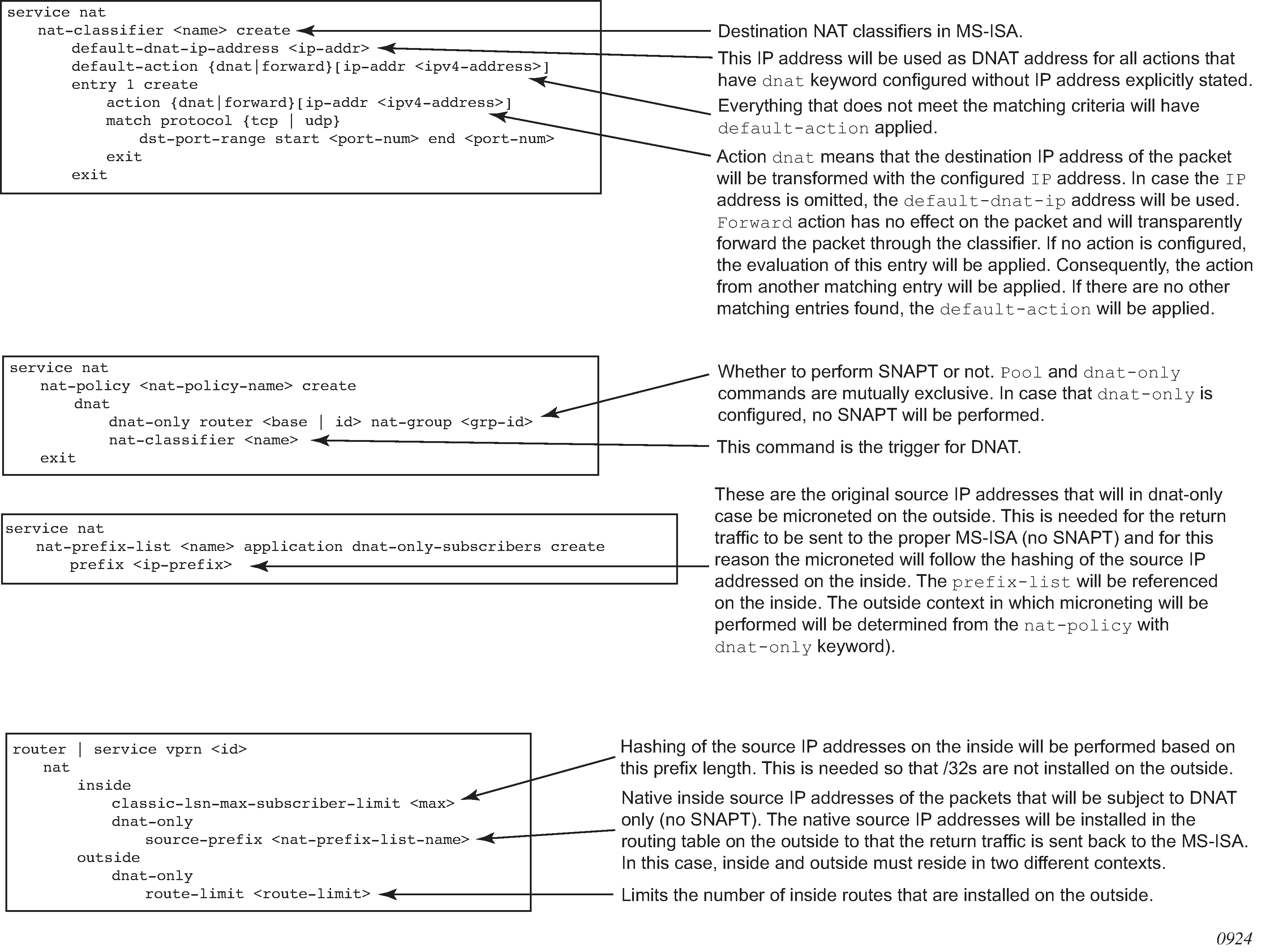
LSN – multiple NAT policies per inside routing context
Restrictions
The following restrictions apply to multiple NAT policies per inside routing context:
There is no support for L2-Aware NAT.
DS-Lite and NAT64 diversion to NAT is supported only through IPv6 filters.
The default NAT policy is counted toward this limit (8).
Multiple NAT policies per inside routing context
The selection of the NAT pool and the outside routing context is performed through the NAT policy. Multiple NAT policies can be used within an inside routing context. This feature effectively allows selective mapping of the incoming traffic within an inside routing context to different NAT pools (with different mapping properties, such as port-block size, subscriber-limit per pool, address-range, port-forwarding-range, deterministic vs non-deterministic behavior, port-block watermarks, and so on) and to different outside routing contexts. NAT policies can be configured:
via filters as part of the action nat command
via routing with the destination-prefix command within the inside routing context
The concept of the NAT pool selection mechanism based on the destination of the traffic via routing is shown in Pool selection based on traffic destination.
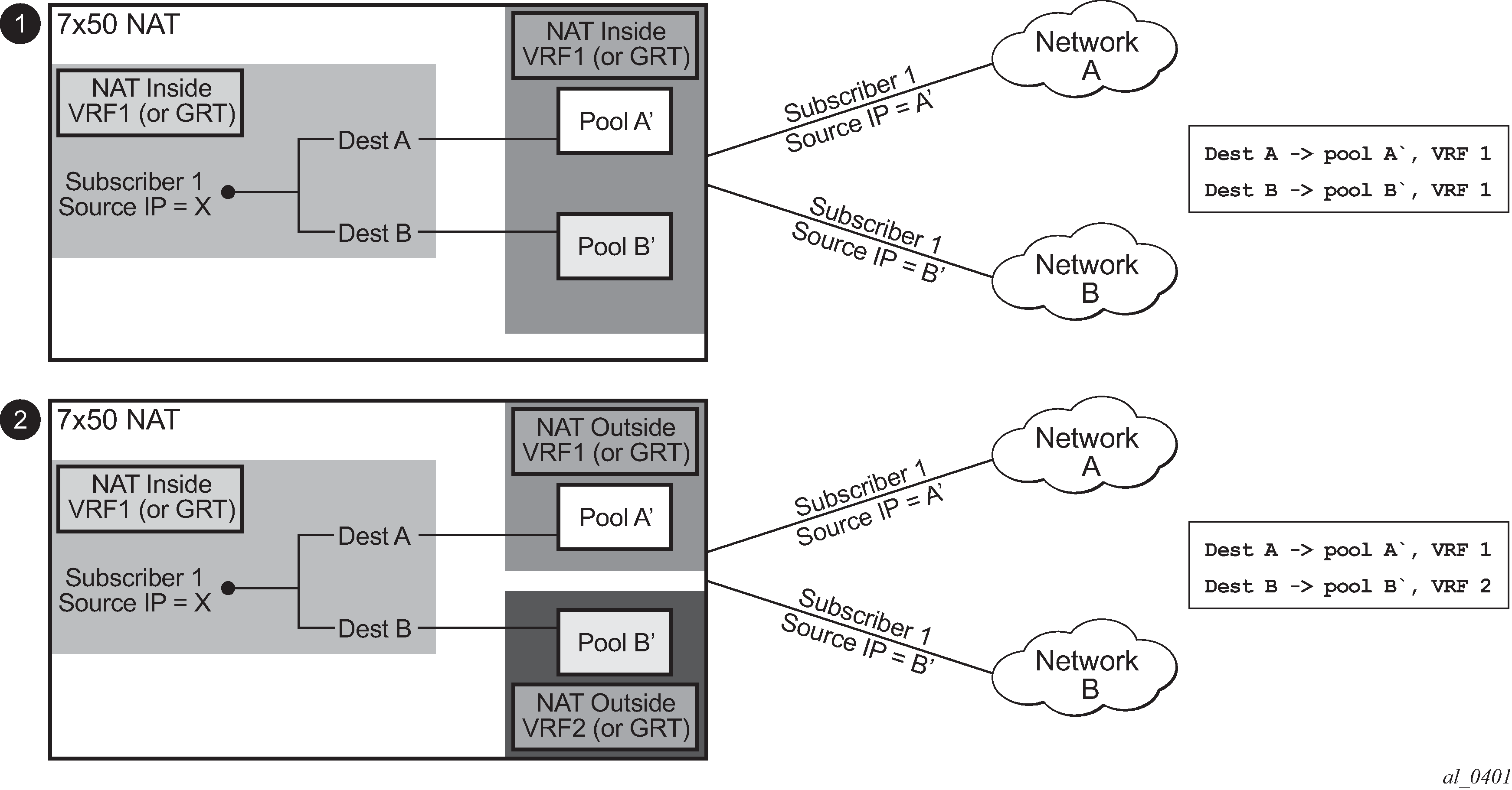
Diversion of the traffic to NAT based on the source of the traffic is shown in NAT pool selection based on the inside source IP address.
Only filter-based diversion solution is supported for this case. The filter-based solution can be extended to a 5 tuple matching criteria.
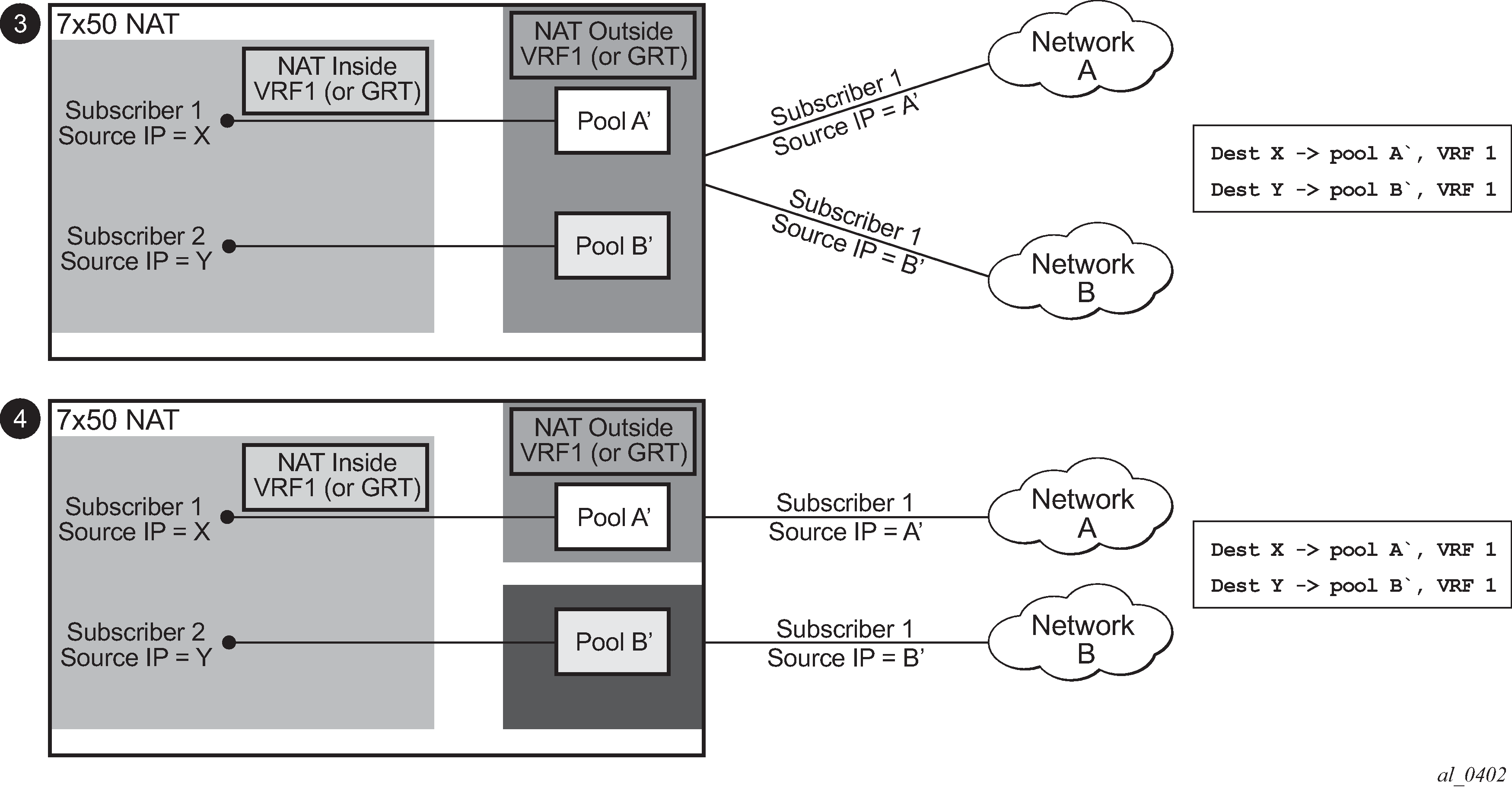
The following considerations must be taken into account when deploying multiple NAT policies per inside routing context:
The inside IP address can be mapped into multiple outside IP addresses based on the traffic destination. The relationship between the inside IP and the outside IP is 1:N.
In case where the source IP address is selected as a matching criteria for a NAT policy (or pool) selection, the inside IP address always stays mapped to the same outside IP address (relationship between the inside IP and outside IP address is, in this case, 1:1)
Static Port Forwards (SPF); each SPF can be created only in one pool. This means that the pool (or NAT policy) must be an input parameter for SPF creation.
Routing approach for NAT diversion
The routing approach relies on upstream traffic being directed (or diverted) to the NAT function based on the destination-prefix command in the config>service>vprn/router>nat>inside CLI context. In other words, the upstream traffic is NAT’d only if it matches a preconfigured destination IP prefix. The destination-prefix command creates a static route in the routing table of the inside routing context. This static route diverts all traffic with the destination IP address that matches the created entry, toward the MS-ISA. The NAT function itself is performed when the traffic is in the correct context in the MS-ISA.
The CLI for multiple NAT policies per inside routing context with routing based diversion to NAT is the following:
service vprn/router
   nat
        inside
              destination-prefix <ip-prefix/length>  nat-policy <policy-name>]
                           :
                           :
or, for example:
service vprn/router
   nat
        inside
              destination-prefix 10.20.10.0/24  nat-policy policy-1
         destination-prefix 10.30.30.0/24  nat-policy policy-1
         destination-prefix 10.40.40.0/24  nat-policy policy-2
Different destination prefixes can reference a single NAT policy (policy-1 in this case).
In case that the destination-policy does not directly reference the NAT policy, the default NAT policy is used. The default NAT policy is configured directly in the vprn/router>nat>inside context.
After the destination-prefix command referencing the NAT policy is configured, an entry in the routing table is created that directs the traffic to the MS-ISA.
Filter-based approach
A filter-based approach diverts traffic to NAT based on the IP matching criteria shown in the CLI below.
*A:right-a21>config>filter>ip-filter>entry# match
  - match [protocol <protocol-id>]
  - no match

 <protocol-id>        : protocol numbers - [0..255] (Decimal,
                                Hexadecimal, or Binary representation).
                        Supported IANA IP protocol names -
                                none|crtp|crudp|egp|eigrp|encap|ether-ip|
                                gre|icmp|idrp|igmp|igp|ip|ipv6|ipv6-frag|ipv6-icmp|
                                ipv6-no-nxt|ipv6-opts|ipv6-route|isis|iso-ip|l2tp|
                                ospf-igp|pim|pnni|ptp|rdp|rsvp|sctp|stp|tcp|udp|vrrp
                        * - udp/tcp wildcard

 [no] dst-ip          - Configure dest. ip match condition
 [no] dst-port        - Configure destination port match condition
 [no] port            - Configure port match condition
 [no] src-ip          - Configure source ip match condition
 [no] src-port        - Configure source port match condition
The CLI for the filter-based diversion in conjunction with multiple NAT policies is shown below:
filter
    entry
      action nat [nat-policy <nat-policy-name>]
The association with the NAT policy is made after the filter is applied to the SAP.
Multiple NAT policies and deterministic NAT
Combination of deterministic LSN44, non-deterministic LSN44, and MNP
Deterministic LSN44 is supported in combination with multiple NAT policies (MNP) based on the destination prefix or on a filter term in non-deterministic LSN44. For simplicity, the destination prefix configuration is used throughout this section instead of the filter terms. However, the combination of deterministic and non-deterministic LSN44 can lead to conflicting scenarios for which the outcomes must be well defined.
The reasons for these conflicting scenarios are the following:
In private to public (or inside to outside) direction, deterministic NAT uses source IP addresses of the traffic as a match criterion to find the correct NAT pool and outside routing context. This is performed through configuration where each source prefix is associated with a NAT policy.
In contrast, non-deterministic NAT uses destination IP addresses of the traffic as a match criterion to find the correct NAT pool and outside routing context. This is performed through configuration where each destination prefix is explicitly associated with its own NAT policy.
If both NAT variants are used simultaneously in the same inside NAT routing context, then the conflict resulting from different NAT policies for the same traffic must be resolved. Deterministic and non-deterministic NAT must always use different NAT policies within the same inside routing context.
The rules used to resolve this conflict are:
Destination prefixes are used to determine the outside routing context from their associated NAT policies. A NAT policy must be explicitly defined for each destination prefix.
When the outside routing context is determined, the pool selection within that routing context is selected based on the NAT policies associated with the source prefixes.
This means that the outside routing context in both NAT policies must match. If they do not match, traffic is dropped.
This logic ensures that traffic intended for NAT processing is identified based on the traffic destination (destination-prefix) while the pool selection (with outside IP addresses) is determined by the source prefix.
This is useful when non-deterministic NAT and static 1:1 NAT are simultaneously used in the same inside routing context. In this case, a customer to which NAT’d traffic is destined can change and re-purpose its routes that can then be dynamically advertised to the NAT operator. At the same time, the NAT operator who is providing static 1:1 NAT can ensure that its clients are predictably mapped to static outside IP addresses because the source prefixes and their associated NAT policies are not changed, even if the destination prefixes are changed.
An example of a supported scenario is shown in MNP and deterministic NAT44 where all destination prefixes are explicitly associated with NAT policies (no destination-prefix is using a default NAT policy) and the source prefixes are explicitly mapped to a different set of NAT policies. The outside routing contexts in the two NAT policies for traffic matching destination and source prefixes simultaneously, must match.
As shown in MNP and deterministic NAT44, traffic from the source network 10.10.0.0/24 is mapped to two different pools in two different outside VPRNs based on the pool names configured in NAT policies associated with the source prefixes. The actual outside VPRN is selected based on the NAT policy associated with the relevant destination prefix.
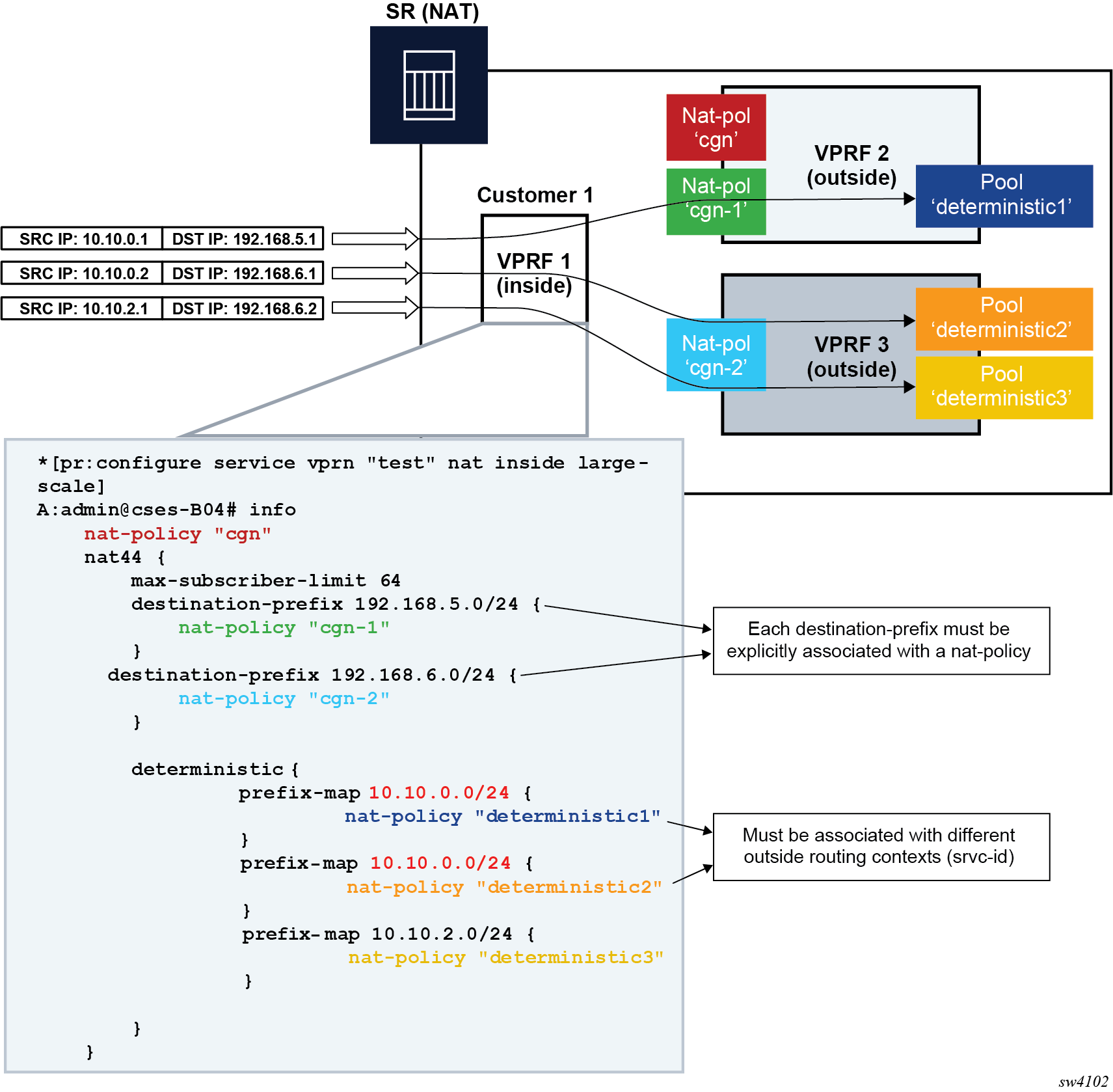
Multiple NAT policies with DS-Lite and NAT64
DS-Lite and NAT64 diversion to NAT with multiple NAT policies is supported only through IPv6 filters.
Classic CLI
configure
   filter
      ipv6-filter
         entry <entry-id> [create]
            action nat nat-type <nat-type> [nat-policy <nat-policy-name>]
            exit
         exit
      exit
   exit
Where the nat-type parameter can be either dslite or NAT64.
The DS-Lite AFTR address and NAT64 destination prefix configuration under the corresponding (DS-Lite or NAT64) router/vprn>nat>inside context is mandatory. This is even when only filters are needed for traffic diversion to NAT.
For example, every AFTR address and NAT64 prefix that is configured as a match criteria in the filter, must also be duplicated in the router/vprn>nat>inside context. However, the opposite is not required.
IPv6 traffic with the destination address outside of the AFTR/NAT64 address/prefix follows normal IPv6 routing path within the 7750 SR.
Default NAT policy
The default nat-policy is always mandatory and must be configured under the router/vprn>nat>inside context. This default NAT policy can reference any configured pool in the needed ISA group. The pool referenced in the default NAT policy can be then overridden by the NAT policy associated with the destination-prefix in LSN44 or by the NAT policy referenced in the ipv4/ipv6-filter used for NAT diversion in LSN44/DS-Lite/NAT64.
The NAT CLI nodes fail to activate (be brought out of the no shutdown state), unless a valid NAT policy is referenced in the router/vprn>nat>inside context.
Scaling considerations
Each subscriber using multiple policies is counted as one subscriber for the inside resources scaling limits (such as the number of subscribers per MS-ISA), and counted as one subscriber per (subscriber and policy combination) for the outside limits (subscriber-limit subscribers per IP; port-reservation port/block reservations per subscriber).
Multiple NAT policies and SPF configuration considerations
Any Static Port Forward (SPF) can be created only in one pool. This pool, which is referenced through the NAT policy, has to be specified at the SPF creation time, either explicitly through the configuration request or implicitly via defaults.
Explicit requests are submitted either via SAM or via CLI:
tools perform nat port-forwarding-action lsn
 - lsn create router <router-instance> [b4 <ipv6-address>] [aftr <ipv6-address>] ip <ip-address> protocol {tcp|udp} [port <port>] lifetime <lifetime> [outside-ip <ipv4-address>] [outside-port <port>] [nat-policy <nat-policy-name>]
In the absence of the NAT policy referenced in the SPF creation request, the default nat-policy command under the vprn/router>nat>inside context is used.
The consequence of this is that the operator must know the NAT policy in which the SPF is to be created. The SPF cannot be created via PCP outside of the pool referenced by the default NAT policy, because PCP does not provide means to communicate NAT policy name in the SPF creation request.
The static port forward creation and their use by the subscriber types must follow these rules:
default NAT policy
Any subscriber type can use an SPF created in the pool referenced by the default NAT policy.
deterministic LSN44 NAT policy
Only deterministic LSN44 subscribers matching the configured prefix can use the SPF created in the pool referenced by the deterministic LSN44 prefix NAT policy.
deterministic DS-Lite NAT policy
Only deterministic DS-Lite subscribers matching the configured prefix can use the SPF created in the pool referenced by the deterministic DS-Lite prefix NAT policy.
LSN44 filter based NAT policy
Only LSN44 subscribers matching the configured filter entry can use the SPF created in the pool referenced by the non-deterministic LSN44 NAT policy within the filter.
DS-Lite filter based NAT policy
Only DS-Lite subscribers matching the configured filter entry can use the SPF created in the pool referenced by the DS-Lite NAT policy within the filter.
NAT64 filter based NAT policy
Only NAT64 subscribers matching the configured filter entry can use the SPF created in the pool referenced by the NAT64 NAT policy within the filter.
When the last relevant policy for a specific subscriber type is removed from the virtual router, the associated port forwards are automatically deleted.
Multiple NAT policies and forwarding considerations
SPF with multiple NAT policies and Bypassing NAT policy rule describe specific scenarios that are more theoretical and are less likely to occur in reality. However, they are described here for the purpose of completeness.
SPF with multiple NAT policies represents the case where traffic from the WEB server 10.1.1.1 is initiated toward the destined network 10.11.0.0/8. Such traffic ends up translated in the Pool B and forwarded to the 10.11.0.0/8 network even though the static port forward has been created in Pool A. In this case, the NAT policy rule (dest 10.11.0.0/8 pool B) determines the pool selection in the upstream direction (even though the SPF for the WEB server already exists in the Pool A).
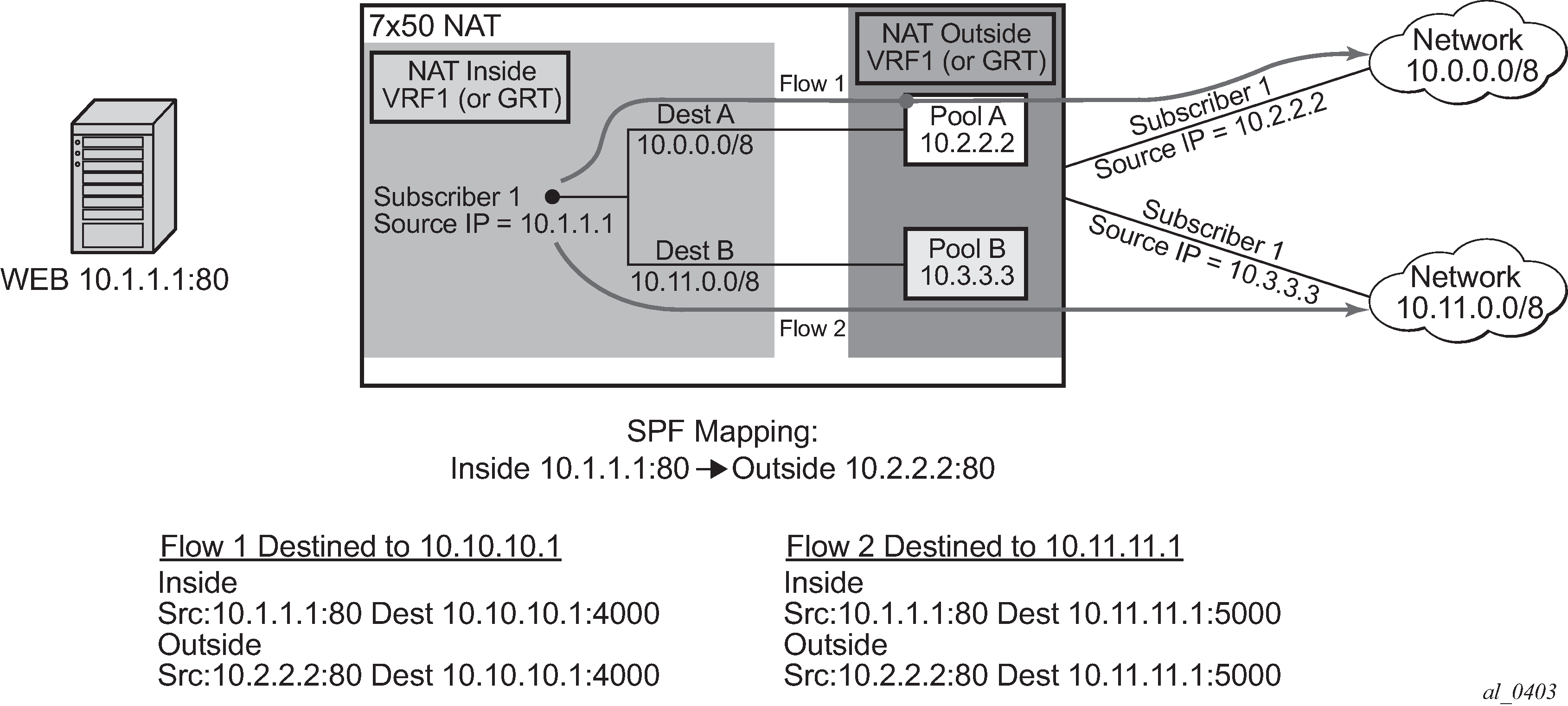
The next example in Bypassing NAT policy rule shows a case where the Flow 1 is initiated from the outside. Because the partial mapping matching this flow already exists (created by SPF) and there is no more specific match (FQF) present, the downstream traffic is mapped according to the SPF (through Pool A to the Web server). At the same time, a more specific entry (FQF) is created (initiated by the very same outside traffic). This FQF now determines the forwarding path for all traffic originating from the inside that is matching this flow. This means that the Flow 2 (reverse of the Flow 1) is not mapped to an IP address from the pool B (as the policy dictates) but instead to the Pool A which has a more specific match.
A more specific match would be in this case fully qualified flows (FQF) that contains information about the foreign host: <host, inside IP/port, outside IP/port, foreign IP address/port, protocol>.
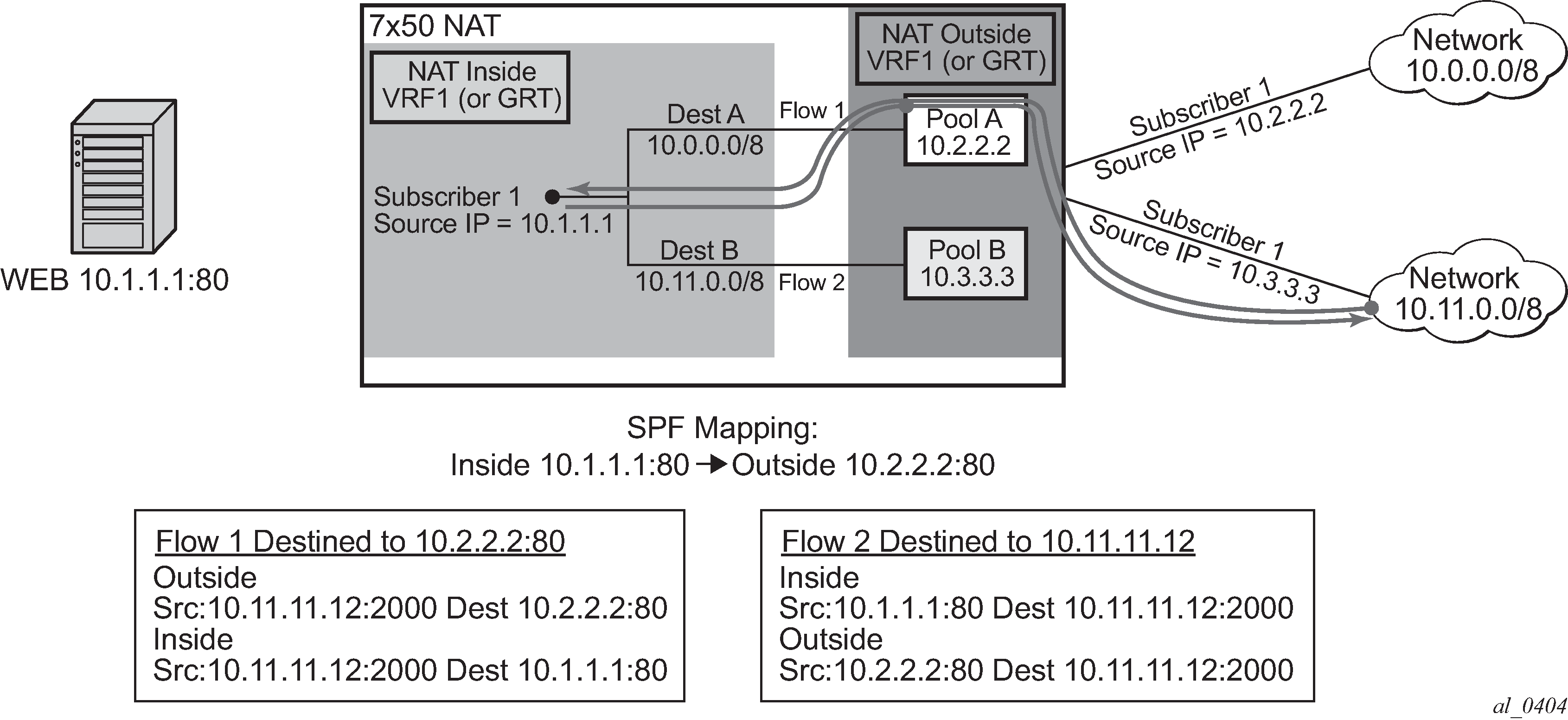
Logging
When multiple NAT policies per inside routing context are deployed, a new policy-id parameter is added to specific syslog messages. The format of the policy-id is:
plcy-id XX
Where XX is an arbitrary unique number per inside routing context assigned by the router. This number, represents the corresponding NAT policy. Because the maximum number of NAT policies in the inside routing context is 8, the policy-id value is also a numerical value in the range 1 to 8.
The introduction of the policy-id in logs is necessary because of the bulk-operations associated with multiple NAT policies per inside routing context. A bulk operation, for example, represents the removal of the nat-policy from the configuration, shutting down the NAT pool, or removing an IP address range from the pool. Removing a NAT accounting policy in case of RADIUS NAT logging does not trigger a summarization log because an acct-off message is sent. Such operations have a tendency to be heavy on NAT logging because they affect a large number of NAT subscribers at the same time. Summarization logs are introduced to prevent excessive logging during bulk operations. For example, the NAT policy deletion can be logged with a single (summarized) entry containing the policy-id of the NAT policy that was removed and the inside service-id. Because all logs contain the policy-id, a single summarization free log can be compared to all map2 logs containing the same policy-id to determine for which subscribers the NAT mappings have ceased. Map and Free logs are generated when the port-block for the subscribers are allocated and de-allocated.
Summarization log is always generated on the CPM, regardless of whether the RADIUS logging is enabled or not. A summarization log simply cannot be generated via RADIUS logging because the RADIUS accounting message streams (start/interim-updates/stop) are always generated per subscriber. In other words, for RADIUS logging, the summarization log would need to be sent to each subscriber, which defeats the purpose of the summarization logs.
A summarization log on the CPM is generated:
When the NAT policy is removed, with a single NAT policy per inside routing context, a summarization log is generated with only one field: inside srvc-id (vprn or base). This is sufficient because there is only one NAT policy per inside routing context. To determine subscribers for which NAT mappings are terminated, the operator should search all most recent map logs matching the service-id from the summarization log.
With multiple NAT policies per inside routing context, the inside srvc-id and the policy-id are included in the summarization log (no outside IPs, outside srvc-id, port-block or source IP).
A log search based on the policy-id and inside srvc-id should reveal all subscribers whose mappings were affected by the NAT policy removal.
When the pool is shutdown, the router sends a summarization log that includes the outside srvc-id and all IP address ranges configured in the pool. No other parameters are included in the summarization log.
A log search based on the outside IP address and outside srvc-id should reveal all subscribers for which the NAT mappings have ceased.
When an IP address-range is removed from the pool. The router sends a summarization log that includes the outside srvc-id and the IP address range that has been removed. No other parameters are included in the summarization log.
A log search based on the outside IP addresses in the range and the outside srvc-id should reveal all subscribers for which the NAT mappings have ceased.
when the last AFTR address is removed
when DS-Lite/NAT64 node is shutdown
when deterministic NAT prefixes are created or removed
Summarization logs in RADIUS logging:
The summarization log for bulk operation while RADIUS logging is generated only in the CPM (syslog). This means that for bulk operations with RADIUS logging, the operator has to rely on RADIUS logging as well as on the CPM logging.
An open log sequence in RADIUS, for example a map for the <inside IP 1, outside IP 1,port-block 1> followed at some later time with a map for <inside IP 2, outside IP 1, port-block 1>, is an indication that the free log for <inside IP 1, outside IP 1,port-block 1> is missing. This means that either the free log for <inside IP 1, outside IP 1,port-block 1> was lost or that a policy, pool, and address-range was removed from the configuration. In the latter case, the operator should look in the CPM log for the summarization message.
The summarization logs are enabled via the event control 2021 tmnxNatLsnSubBlksFree which is by default suppressed. The event control 2021 is also used to report when all blocks for the subscriber are freed.
Default DMZ Host
A default demilitarized zone (DMZ) host is a node to which all unmatched traffic from the outside can be redirected. This redirection is achieved by changing the destination IPv4 address in the traffic header to the IPv4 address of the default DMZ host. On the default DMZ host, unmatched traffic can be inspected as part of a threat analysis.
A default DMZ host does not have to be directly connected to the inside NAT segment, but can be located deeper in the network. The default DMS host does not send any replies to the unknown traffic; and therefore, there is no state maintained for the unknown traffic in NAT. The rate of unmatched traffic sent to the default DMZ host can be restricted by configuration.
In the redirected traffic with swapped destination IPv4 addresses, the Layer 3 and Layer 4 (UDP and TCP) checksums are recalculated.
The following example show a basic default DMZ host configuration.
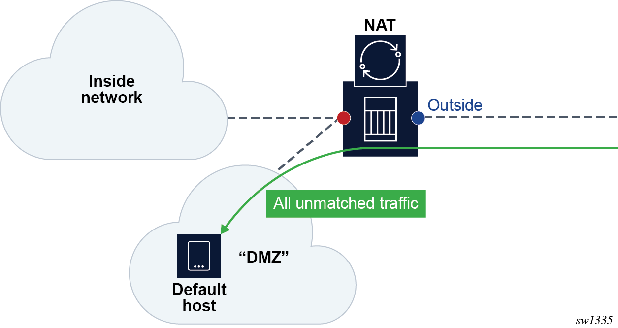
The following example shows a default DMZ host for LSN in a VPRN service configuration.
MD-CLI
[ex:/configure service vprn "demo-vprn" nat outside pool "demo-pool" large-scale default-host
configure service vprn “demo-vprn” nat outside pool “demo-pool” large-scale
    default-host {
        ip-address 10.10.10.10
    }
classic CLI
*A:node-2>config>router#
            nat
                outside
                    pool "demo-pool" nat-group 1 type large-scale create
                        default-host 10.10.10.10 inside-router-id "Base" rate 10
                    exit
                exit
            exit
            no shutdown
----------------------------------------------
The following example shows a L2-aware NAT in a “Base” router configuration.
MD-CLI
[ex:/configure router "Base" nat outside pool "demo-pool" l2-aware]
configure router “Base” nat outside pool “demo-pool” l2-aware
    default-host {
        ip-address 10.10.10.10
        inside-router-instance “Base”
        rate-limit 100
    }
classic CLI
*A:node-2>config#
    router
         nat
            outside
                pool "demo-pool" nat-group 1 type l2-aware create
                    default-host 10.10.10.10 inside-router-id "Base" rate 100
                exit
--------------------------------------------------
NAT and CoA
RADIUS Change of Authorization (CoA) can be used in subscriber management (ESM) to modify the NAT behavior of the subscriber. This can be performed by:
replacing a NAT policy in a subscriber profile for the L2-Aware NAT subscriber
-
replacing or removing a NAT policy within the IP filter for the ESM subscriber using LSN44, DS-Lite or NAT64
-
modifying DNAT parameters directly via CoA for the L2-Aware subscriber
CoA and NAT policies
The behavior for NAT policy changes via CoA for LSN and L2-Aware NAT is summarized in NAT policy changes via CoA .
| Action | Outcome | Remarks | |
|---|---|---|---|
| L2-Aware | LSN | ||
CoA - replacing NAT policy |
Stale flows using the old NAT policy are cleared after 5 seconds. New flows immediately start using a new NAT policy. Restrictions: Allowed only when the previous change is completed (need to wait for a 5 second interval during which the stale mappings caused by previous CoA are purged). |
Stale flows using the old NAT policy continue to exist and are used for traffic forwarding until they are naturally timed-out or TCP- terminated. The exception to this is when the reference to the NAT policy in the filter was the last one for the inside VRF. In this scenario, the flows from the removed NAT policy are cleared immediately. New flows immediately start using new NAT policy. |
A NAT policy change via CoA is performed by changing the sub-profile for the ESM subscriber or by changing the ESM subscriber filter in the LSN case. 1 A sub-profile change alone does not trigger accounting messages in L2-Aware NAT and consequently the logging information is lost. To ensure timely RADIUS logging of the NAT policy change in L2-Aware NAT, each CoA must, in addition to the sub-profile change, also do one of the following:
Both of the above events trigger an accounting update at the time when CoA is processed. This keeps NAT logging current. |
(cont.)
|
|||
In non-ESM environments, the NAT policy can be changed by replacing the interface filter via CLI for LSN case.
The SLA profile has to be changed and not just refreshed. In other words, replacing the existing SLA profile with the same one does not trigger a new accounting message.
CoA and DNAT
Adding, removing or replacing DNAT parameters in LSN44 can be achieved through NAT policy manipulation in an IP filter for ESM subscriber. The rules for NAT policy manipulation via CoA are given in NAT policy changes via CoA . In L2-Aware NAT, CoA can be used to:
Enable or disable DNAT functionality while leaving the Source Network Address and Port Translation (SNAPT) uninterrupted.
-
Modify the default destination IP address in DNAT.
After the DNAT configuration is modified via CoA (enable or disable DNAT or change the default DNAT IP address), the existing flows affected by the change remain active for 5 more seconds while the new flows are created in accordance with the new configuration. After a 5 second timeout, the stale flows are cleared from the system.
The RADIUS attribute used to perform DNAT modifications is a composite attribute with the following format:
Alc-DNAT-Override (234) = ‟{<DNAT_state> | <DNAT-ip-addr>},[nat-policy]”
where: DNAT state = none | disable → and the DNAT-ip-addr parameter are mutually exclusive.
DNAT-ip-addr = Provides an implicit enable with the destination IPv4 address in dotted format (a.b.c.d) → and the DNAT-state parameter are mutually exclusive.
nat-policy = nat-policy name → This is an optional parameter. If it is not present, then the default NAT policy is assumed.
For example:
Alc-DNAT-Override=none → This negates any previous DNAT related override in the default nat-policy. Consequently, the DNAT functionality is set as originally defined in the default nat-policy. In case that the ‛none’ value is received while DNAT is already enabled, a CoA ACK is sent back to the originator.
Alc-DNAT-Override =none,nat-pol-1 → This re-enables DNAT functionality in the specific NAT policy with the name nat-policy-1.
Alc-DNAT-Override =none,10.1.1.1 → The DNAT-state and DNAT-ip-addr parameters are mutually exclusive within the same Alc-DNAT-Override attribute. Although a CoA ACK reply is returned to the RADIUS server, an error log message is generated in the SR OS indicating that the attempted override failed.
Alc-DNAT-Override =10.1.1.1 → This changes the default DNAT IP address to 1.1.1.1 in the default NAT policy. In case DNAT was disabled before receiving this CoA, it is implicitly enabled.
Alc-DNAT-Override =10.1.1.1,nat-pol-1 → This changes the default DNAT IP address to 10.1.1.1 in the specific NAT policy named nat-policy-1. DNAT is implicitly enabled if it was disabled before receiving this CoA.
The combination of sub-fields with the Alc-DNAT-Override RADIUS attribute and the corresponding actions are shown in CoA and DNAT .
| DNAT-state | DNAT-ip-addr | NAT policy | DNAT action in L2-Aware NAT |
|---|---|---|---|
none |
- |
- |
Re-enable DNAT in the default NAT policy. If DNAT was enabled before receiving this CoA, then no specific action is carried out by the SR OS with the exception of sending the CoA ACK back to the CoA server. This negates any previous DNAT-related override in the default nat-policy. Consequently, the DNAT functionality is set as originally defined in the default nat-policy. If the DNAT classifier is not present in the default nat-policy when this CoA is received, an error log message is raised. |
none |
- |
nat-pol-name |
Re-enable DNAT in the referenced NAT policy. This negates any previous DNAT related override in the referenced nat-policy. Consequently, the DNAT functionality is set as originally defined in the referenced nat-policy. If the DNAT classifier is not present in the referenced nat-policy when this CoA is received, a CoA ACK reply is returned to the RADIUS server and an error log message is generated in the SR OS indicating that the attempted override has failed. |
none |
a.b.c.d |
- |
These two parameters are mutually exclusive in the same Alc-DNAT-Override attribute. Although a CoA ACK reply is returned to the RADIUS server, an error log message is generated in SR OS indicating that the attempted override has failed. |
none |
a.b.c.d |
nat-pol-name |
DNAT-state and DNAT-ip-address parameters are mutually exclusive in the same Alc-DNAT-Override attribute. Although a CoA ACK reply is returned to the RADIUS server, an error log message is generated in SR OS indicating that the attempted override has failed. |
disable |
- |
- |
Disable DNAT in the default NAT policy. If the DNAT classifier is not present in the default nat-policy when this CoA is received, a CoA ACK reply is returned to the RADIUS server and an error log message is generated in the SR OS indicating that the attempted override has failed. |
disable |
- |
nat-pol-name |
Disable DNAT in the referenced NAT policy. If the DNAT classifier is not present in the referenced nat-policy when this CoA is received, a CoA ACK reply is returned to the RADIUS server and an error log message is generated in SR OS indicating that the attempted override has failed. |
disable |
a.b.c.d |
- |
The DNAT-state and DNAT-ip-address parameters are mutually exclusive in the same Alc-DNAT-Override attribute. Although a CoA ACK reply is returned to the RADIUS server, an error log message is generated in SR OS indicating that the attempted override has failed. |
disable |
a.b.c.d |
nat-pol-name |
The DNAT-state and DNAT-ip-address parameters are mutually exclusive in the same Alc-DNAT-Override attribute. Although a CoA ACK reply is returned to the RADIUS server, an error log message is generated in the SR OS indicating that the attempted override has failed. |
- |
a.b.c.d |
- |
The default destination IP address is changed in the default NAT policy. |
- |
a.b.c.d |
nat-pol-name |
The default destination IP address is changed in the referenced NAT policy. |
- |
- |
- or nat-pol-name |
A CoA NAK (error) is generated. Either DNAT-state or DNAT-ip-address parameters must be present in the Alc-DNAT-Override attribute. |
If multiple Alc-DNAT-Override attributes with conflicting actions are received in the same CoA or Access-Accept, the action that occurred last takes precedence.
For example, if the following two Alc-DNAT-Override attributes are received in the same CoA, the last one takes effect and consequently DNAT is disabled in the default NAT policy:
Alc-DNAT-Override = ‟10.1.1.1‟
Alc-DNAT-Override = ‟disable‟
Modifying an active NAT prefix list or NAT classifier via CLI
Modifying active NAT prefix list or NAT classifier describes the outcome when the active NAT prefix list or NAT classifier is modified using CLI.
| Action | Outcome | Remarks | |
|---|---|---|---|
| L2-Aware | LSN | ||
CLI – Modifying prefix in the NAT prefix list |
Existing flows are always checked whether they comply with the NAT prefix list that is currently applied in the subscriber profile for the subscriber. If the flows do not comply with the current NAT prefix list, they are cleared after 5 seconds. The new flows immediately start using the updated settings. |
Changing the prefix in the NAT prefix list internally re-subnets the outside IP address space. |
A NAT prefix list is used with multiple NAT policies in L2-Aware NAT and for downstream Internal subnet in DNAT-only scenario for LSN. The prefix can be modified (added, removed, remapped) at any time in the NAT prefix list, while the NAT policy must be first shut down via CLI. |
CLI – Modifying or replacing the NAT classifier |
Existing flows are always checked whether they comply with the NAT classifier that is currently applied in the active NAT policy for the subscriber. If the flows do not comply with the current NAT classifier, they are cleared after 5 seconds. The new flows immediately start using the updated settings. |
Changing the NAT classifier have the same effect as in L2-Aware NAT; all existing flows using the NAT classifier are checked whether they comply with this classifier or not. |
The NAT classifier is used for DNAT. NAT classifier is referenced in the NAT policy. |
CLI - Removing or adding NAT policy in NAT prefix list |
Blocked |
Not applicable |
|
CLI - Removing or adding NAT policy in the subscriber profile |
Blocked |
Not applicable |
|
CLI - Removing, adding or replacing NAT prefix list under the rtr/nat/inside/DNAT-only |
Not applicable |
This action triggers internally re-subnet the source address space according to the new NAT prefix list. However, the current flows in the MS ISA are not affected by this change. In other words, they are not removed if the associated prefix is removed from the prefix list. |
|
Watermarks
Watermarks can be configured to monitor the actual usage of sessions, ports, and port blocks.
For each watermark, a high and a low value must be set. When the high threshold value is crossed in the upward direction, an event is generated (SNMP trap), notifying the operator that a NAT resource may be approaching exhaustion. When the low threshold value is crossed in the downward direction, a similar event is generated (clearing the first event, notifying the operator that the resource utilization has dropped below the low threshold value.
Watermarks can be defined on the NAT group, pool, and policy level.
NAT group
Watermarks can be placed to monitor the total number of sessions on an MDA.
NAT pool on each NAT group member
Watermarks can be placed to monitor the port block occupancy in a pool within each NAT group member.
policy
In the policy the operator can define watermarks on session and port usage. In both cases, it is the usage per subscriber (for L2-Aware NAT) or per host (for large-scale NAT) that are monitored.
Port forwards
Port forwards allow devices on the public side of NAT (NAT outside) to initiate sessions toward those devices, usually servers, that are hidden behind NAT (NAT inside). Another term for port forwards is NAT pinhole.
A port forward represents a previously created (before any traffic is received from the inside) mapping between a TCP/UDP port on the outside IP address and a TCP/UDP port on the inside IP address assigned to a device behind the NAT. This mapping can be created statically by configuration (such as CLI, MIB, YANG, or NETCONF), or it can be created dynamically with protocols such as PCP or UPnP. Port forwards are supported only in NAT pools in Network Address and Port Translation (NAPT) mode. NAT pools in 1:1 mode do not support configured port forwards because, by default, the pools allow traffic from the outside to the inside and this cannot be disabled. Pools in 1:1 mode (whether protocol agnostic) do not perform port translation; therefore the inside and outside always match.
In UPnP, the forwarded ports are created with the port range of the NAT subscriber, whereas with PCP and Static Port Forwards (SPF), the forwarded ports are allocated from a dedicated port range outside of the port blocks allocated to individual NAT subscribers. There are two ranges dedicated to port forwards in NAT:
-
well-known ports (1 to 1023)
This range is always enabled and cannot be disabled in NAT pools that support configured port forwards (non 1:1 NAT pools).
-
ports from the ephemeral port range (1025 to 65535)
Port forwards from the ephemeral port space must be explicitly enabled by configuration. They are allocated from a contiguous block of ports where upper and lower limits are defined. Ports reserved for port forwards allocated in the ephemeral port space are also referred to as wildcard ports.
Port forwarding ranges (well-known ports and wildcard ports) are shared by all NAT subscribers on a specific outside IP address. Port blocks that are individually assigned to the subscriber cannot be allocated from the port forwarding range. The wildcard port forwarding range can be configured only when the pool is administratively disabled.
See the Port Control Protocol (PCP) and Universal plug and play Internet Gateway Device service sections as well as the SR OS R22.x.Rx Software Release Notes for more information about these protocols and the supported NAT types.
Static port forwards
In classic CLI, NAT Static Port Forwards (SPFs) can be managed through configuration or with a tools command. In the MD-CLI and NETCONF, a tools command manages SPFs.
If the tools command is configured to manage SPFs and preserve SPFs across reboots, then persistency of the SPF must be enabled with the configure system persistence nat-port-forwarding command for both classic CLI and MD-CLI. With persistency enabled, SPF configuration is stored on the compact flash.
The following are command syntax and sample configuration for Large Scale NAT (LSN):
- MD-CLI
A:admin@sr-1s# tools perform nat port-forwarding-action lsn ? lsn add router <string> [b4 <ipv6 address>] [aftr <ipv6 address>] ip <IP address> protocol <keyword> [port <number>] lifetime <string> [outside-ip <ipv4 address>] [outside-port <number>] [nat-policy <string>] lsn remove router <string> [b4 <ipv6 address>] ip <IP address> protocol <keyword> port <number> [nat-policy <string>] lsn modify router <string> [b4 <ipv6 address>] ip <IP address> protocol <keyword> port <number> lifetime <string> [nat-policy <string>] -
classic CLI
A:cses-V22>config>service>nat>fwd#
lsn router <router-instance> [b4 <ipv6-address>] [aftr <ipv6-address>] ip <ip-address> protocol {tcp|udp} [port <port>] [outside-ip <ipv4-address>] [outside-port <port>] [nat-policy <nat-policy-name>]
*A:Dut-C>config>service>nat>fwd# info detail ---------------------------------------------- lsn router 101 ip 11.11.13.7 protocol udp port 12345 outside-ip 130.0.255.254 outside-port 3171 nat-policy "pol1_for_2001-pool-0" ---------------------------------------------- *A:Dut-C>config>service>nat>fwd#
- port number
- for the source port
- outside-ip ipv4-address
- for the outside IP address
- outside-port number
- for the outside port
- nat-policy string
- for the NAT policy
Port Control Protocol (PCP)
PCP is a protocol that operates between subscribers and the NAT directly. This makes the protocol similar to DHCP or PPP in that the subscriber has a limited but direct control over the NAT behavior.
PCP is designed to allows the configuration of static port-forwards, obtain information about existing port forwards and to obtain the outside IP address from software running in the home network or on the CPE.
PCP runs on each MS-ISA as its own process and make use of the same source-IP hash algorithm as the NAT mappings themselves. The protocol itself is UDP based and is request/response in nature, in some ways, similar to UPnP.
PCP operates on a specified loopback interface in a similar way to the local DHCP server. It operates on UDP and a specified (in CLI) port. As Epoch is used to help recover mappings, a unique PCP service must be configured for each NAT group.
When epoch is lowered, there is no mechanism to inform the clients to refresh their mappings en masse. External synchronization of mappings is possible between two chassis (epoch does not need to be synchronized). If epoch is unsynchronized then the result is clients re-creating their mapping on next communication with the PCP server.
     0                   1                   2                   3
      0 1 2 3 4 5 6 7 8 9 0 1 2 3 4 5 6 7 8 9 0 1 2 3 4 5 6 7 8 9 0 1
     +-+-+-+-+-+-+-+-+-+-+-+-+-+-+-+-+-+-+-+-+-+-+-+-+-+-+-+-+-+-+-+-+
     |  Version = 1  |R|   OpCode    |      Reserved (16 bits)       |
     +-+-+-+-+-+-+-+-+-+-+-+-+-+-+-+-+-+-+-+-+-+-+-+-+-+-+-+-+-+-+-+-+
     |                      Requested Lifetime                       |
     +-+-+-+-+-+-+-+-+-+-+-+-+-+-+-+-+-+-+-+-+-+-+-+-+-+-+-+-+-+-+-+-+
     :                                                               :
     :             (optional) opcode-specific information            :
     :                                                               :
     +-+-+-+-+-+-+-+-+-+-+-+-+-+-+-+-+-+-+-+-+-+-+-+-+-+-+-+-+-+-+-+-+
     :                                                               :
     :             (optional) PCP Options                            :
     :                                                               :
     +-+-+-+-+-+-+-+-+-+-+-+-+-+-+-+-+-+-+-+-+-+-+-+-+-+-+-+-+-+-+-+-+
The R-bit (0) indicates request and (1) indicates response. This is a request so (0).
OpCode defined as:
Requested Lifetime: Lifetime 0 means delete.
      0                   1                   2                   3
      0 1 2 3 4 5 6 7 8 9 0 1 2 3 4 5 6 7 8 9 0 1 2 3 4 5 6 7 8 9 0 1
     +-+-+-+-+-+-+-+-+-+-+-+-+-+-+-+-+-+-+-+-+-+-+-+-+-+-+-+-+-+-+-+-+
     |  Version = 1  |R|   OpCode    |   Reserved    |  Result Code  |
     +-+-+-+-+-+-+-+-+-+-+-+-+-+-+-+-+-+-+-+-+-+-+-+-+-+-+-+-+-+-+-+-+
     |                           Lifetime                            |
     +-+-+-+-+-+-+-+-+-+-+-+-+-+-+-+-+-+-+-+-+-+-+-+-+-+-+-+-+-+-+-+-+
     |                             Epoch                             |
     +-+-+-+-+-+-+-+-+-+-+-+-+-+-+-+-+-+-+-+-+-+-+-+-+-+-+-+-+-+-+-+-+
     :                                                               :
     :             (optional) OpCode-specific response data          :
     :                                                               :
     +-+-+-+-+-+-+-+-+-+-+-+-+-+-+-+-+-+-+-+-+-+-+-+-+-+-+-+-+-+-+-+-+
     :             (optional) Options                                :
     +-+-+-+-+-+-+-+-+-+-+-+-+-+-+-+-+-+-+-+-+-+-+-+-+-+-+-+-+-+-+-+-+
As this is a response, R = (1).
The Epoch field increments by 1 every second and can be used by the client to determine if state needs to be restored. On any failure of the PCP server or the NAT to which it is associated Epoch must restart from zero (0).
Result Codes:
0 SUCCESS, success.
1 UNSUPP_VERSION, unsupported version.
2 MALFORMED_REQUEST, a general catch-all error.
3 UNSUPP_OPCODE, unsupported OpCode.
4 UNSUPP_OPTION, unsupported option. Only if the Option was mandatory.
5 MALFORMED_OPTION, malformed option.
6 UNSPECIFIED_ERROR, server encountered an error
7 MISORDERED_OPTIONS, options not in correct order
Creating a Mapping
Client Sends
      0                   1                   2                   3
      0 1 2 3 4 5 6 7 8 9 0 1 2 3 4 5 6 7 8 9 0 1 2 3 4 5 6 7 8 9 0 1
     +-+-+-+-+-+-+-+-+-+-+-+-+-+-+-+-+-+-+-+-+-+-+-+-+-+-+-+-+-+-+-+-+
     |  Protocol     |          Reserved (24 bits)                   |
     +-+-+-+-+-+-+-+-+-+-+-+-+-+-+-+-+-+-+-+-+-+-+-+-+-+-+-+-+-+-+-+-+
     |        Internal port          |   Suggested external port     |
     +-+-+-+-+-+-+-+-+-+-+-+-+-+-+-+-+-+-+-+-+-+-+-+-+-+-+-+-+-+-+-+-+
     :                                                               :
     : Suggested External IP Address (32 or 128, depending on OpCode):
     :                                                               :
     +-+-+-+-+-+-+-+-+-+-+-+-+-+-+-+-+-+-+-+-+-+-+-+-+-+-+-+-+-+-+-+-+
MAP4 opcode is (1). Protocols: 0 – all; 1 – ICMP; 6 – TCP; 17 – UDP.
MAP4 (1), PEER4 (3) and PREFER_FAILURE are supported. FILTER and THIRD_PARTY are not supported.
PORT_SET option
Terminology
The terms internal port and inside port are used interchangeably. They both refer to the original source port before NAT is performed.
The terms external port and outside port are used interchangeably. They both refer to the translated source port after NAT is performed.
The PCP PORT_SET option is defined in RFC 7753, Port Control Protocol (PCP) Extension for Port-Set Allocation, and is used by applications that require a consecutive block of port forwards. The reasons to provide a block of ports in a single request as opposed to multiple requests for single port in a MAP request are described in Section 2 of RFC 7753.
A PCP PORT_SET option indicates to the PCP server (SR OS) that a client needs a block of sequential port forwards. The number of requested port forwards must be greater than one (otherwise, a plain MAP opcode can be used). The ports in the block start at the Internal Port (in MAP opcode) and map to the same number of ports on the outside (or the external side), starting from either the Suggested External Port (in MAP opcode) or from an arbitrary external port. The returned number of ports may be fewer than the requested number, but the number cannot be larger. The allocated port set cannot fall outside of the range defined by the Internal Port (as requested in MAP opcode) plus the PORT_SET Size. Before a port set is assigned to a client, the SR OS always checks if any of the internal ports in the MAP request carrying the PORT_SET option has already been allocated.
The following figure shows an example of PORT_SET option format.
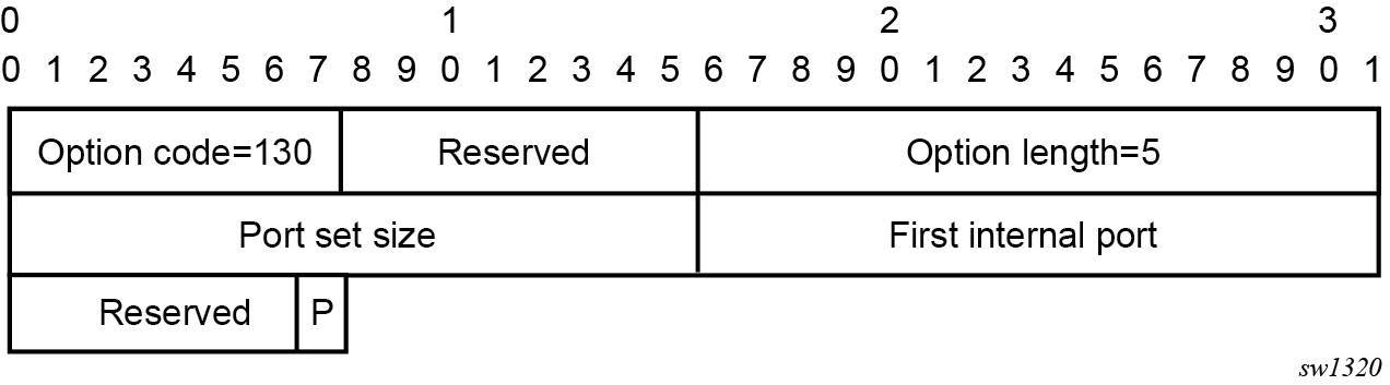
In the MAP request, the needed number of ports is specified in the PORT_SET Size field.
The First Internal Port is set to the same value as the Internal Port field in the MAP opcode.
In the MAP response, the PORT_SET Size represents the number of allocated ports. The First Internal Port represents the first internal port in the port set, which may be different than the Internal Port field in the MAP opcode (see example in Section 6.3 in RFC 7753, overlapping requests). The first external port is the value returned in Assigned External Port field in the MAP opcode.
Enabling the PORT_SET option
The PORT_SET option is enabled with the following CLI:
Classic CLI:
config>service>nat>pcp-server-policy#
    option
        [no] port-set
MD-CLI:
configure
    service {
        nat {
            pcp-server-policy <name> {
                option {
                    port-set <boolean>
                }
            }
        }
    }
Port allocation scheme
The appropriate port set size is determined from the combination of the port set size received via the PORT_SET option and the locally configured policy which may limit the port set size.
If the requested port set is initially not available at the Suggested External Port, an attempt is made to find a new set of ports of the appropriate size. The appropriate PORT_SET size in this context means a combination of the requested PORT_SET size and the local limits set by the operator in the SR OS node.
If the available number of consecutive ports in a set for the specified external IP address is fewer that the requested amount or stated in the policy, the maximum number of available consecutive ports are allocated to the client.
In summary, the SR OS tries to find the biggest available port set (as dictated by the combination of the requested size and local policy), instead of allocating random port sets available at the suggested external port.
Limits and quotas
The maximum number of port forwards per subscriber can be limited with the following CLI:
Classic CLI:
config>service>nat>nat-policy# port-limits forwarding
  - forwarding <limit>
  - no forwarding
MD-CLI:
configure
    service {
        nat {
            nat-policy <name> {
                port-limits {
                }
            }
        }
    }
This limit is the total number of port forwards, regardless of the methods by which the port forwards are requested, either PCP MAP, PORT_SET, or static port forwards.
Port overlaps
PCP clients should not request overlapping ports. Requesting overlapping ports produces an erroneous condition. If this condition occurs, then the request is considered as a refresh of the existing ports. This is described in RFC 7753, Section 4.4.1.
Port allocation example
The following example depicts PCP port allocation with the PORT_SET option in action. For additional examples, see RFC 7753.
In this example, the sequence on the top of PORT_SET example represents the state of the port forwards for an external IP address before the PCP Request with the PORT_SET option is received. The port 1032 (in red) has already been mapped to a source port for the same client or to a different client.
A PCP client requesting an overlapping set of external ports (while internal ports are different) triggers the following action in SR OS (PCP server):
The SR OS checks if the existing mapping is overlapping with the one for this client. It checks to see if the occupied external port is already mapped to one of the requested internal ports from the 20000 to 20009 range for the same client.
If such overlap between internal and external ports is detected (for example, 20001 is mapped to 1032), then this is considered a refresh, and the response is:
opcode: 1(MAP)
internal port: 20,000
assigned external port: 1032
assigned external ip address:192.0.2.3
Every overlapping pair of internal and external ports are individually acknowledged. No new mapping is allocated.
If there is no overlap (when the external port is mapped to a port outside of the 20000 to 20009 range), and no limit is reached, then the SR OS honors the request where it finds any set containing consecutive 10 ports.
In PORT_SET example , there is no overlap (external port 1032 belongs to another client or the same client outside of the 20000 to 20009 range) and consequently a block of 10 ports (following parity) is allocated to the client.

Operational considerations
Consider the following points when the when PCP PORT_SET option is enabled. Points listed below are in accordance with the RFC 7753:
The SR OS attempts to allocate the first external port from the suggested external port. If the port is not available, another port is selected.
Parity is honored.
The PORT_SET size value 0xffff in the request indicates that the client is willing to accept as many ports as the SR OS can offer.
If the requested PORT-SET request cannot be fully (or exactly) satisfied because of the unavailability of the requested consecutive port range, the SR OS tries to find and allocate the next largest port set.
If the SR OS, because of the lack of contiguous port ranges, allocates only a single port, the PORT_SET option is not present in the response.
If the SR OS receives a PCP MAP request, with or without a PORT_SET option that tries to map one or more internal ports or port sets belonging to already existing mappings, then the request is considered to be a refresh request. Each of the matching port or port set mappings is processed independently, as if a separate refresh request was received. Consequently, the SR OS sends a Mapping Update message for each of the mappings.
If multiple PORT_SET options are present in a single PCP MAP request, a MALFORMED_OPTION error is returned.
If the PORT_SET size is zero, a MALFORMED_OPTION error is returned.
If a Prefer Failure option is present, a MALFORMED_OPTION error is returned.
When a PCP request contains both the PORT_SET and Port Reservation Port (N/N+1) options, only the PORT_SET is honored.
PCP (with PORT_SET option or otherwise) should not be configured simultaneously with static port forwards in the same NAT pool. PCP allows for dynamic refreshment of port forwards while static port forwards do not have this capability. As a result, PCP port refresh of a port forward allocated statically may lead to unwanted behavior.
If the PORT_SET capability is added to or removed from an operationally up PCP server on an SR OS node, the server resets its Epoch time and sends a Version 2 ANNOUNCE message as described in the PCP specification.
Universal plug and play Internet Gateway Device service
Universal Plug and Play (UPnP), which is a set of specifications defined by the UPnP forum. One specification is called Internet Gateway Device (IGD) which defines a protocol for clients to automatically configure port mappings on a NAT device. Today, many gaming, P2P, VoIP applications support the UPnP IGD protocol. The SR OS supports the following UPnP version 1 InternetGatewayDevice version 1 features:
Supports only L2-Aware NAT hosts.
Distributed subscriber management is not supported.
The UPnP server runs on NAT ISA and only serves the local L2-Aware NAT hosts on the same ISA.
The UPnP server can be enabled per subscriber by configuring a upnp-policy in the sub-profile.
UPnP discovery is supported.
UPnP eventing is not supported.
The following IGD devices and services are supported:
-
WANDevice
-
WANConnectionDevice
-
WANIPConnection service
-
-
For WANIPConnection services:
-
Optional state variables in a WANIPConnection service are not supported.
-
Optional actions in a WANIPConnection services are not supported.
-
Wildcard ExternalPort is not supported.
-
Only supports wildcard RemoteHost.
-
Up to 64 bytes of port mapping description are supported.
-
The SR OS supports a vendor specific action X_ClearPortMapping. This clears all port mappings of the subscriber belonging to the requesting host. This action has no in or out arguments.
-
-
If the NewExternalPort in an addPortMapping request is same as the external port of one existing UPnP port mapping:
-
If NewInternalClient is different from InternalClient of existing mapping, then the system rejects the request.
-
If NewInternalClient is same as InternalClient of existing mapping:
-
With strict-mode on, if the source IP address of the request is same as InternalClient of existing mapping, then the request is accepted; otherwise the request is rejected.
-
With strict-mode off, the request is accepted.
-
-
-
The system also supports the Alc-UPnP-Sub-Override-Policy RADIUS VSA which can be included in access-accept or CoA request. It can be used to override the upnp-policy configured in sub-profile or disable UPnP for the subscriber. See RADIUS reference guide for detail usage.
Configuring UPnP IGD service
- Configure L2-Aware NAT.
- Create a upnp-policy:
-
Configure the upnp-policy as created in step 2 in the subscriber profile:
config>service
   upnp
            upnp-policy "test" create
                no description
                http-listening-port 5000
                mapping-limit 100
                no strict-mode
            exit
config>subscr-mgmt sub-profile "l2nat-upnp" create nat-policy "l2" upnp-policy "test" exit
NAT Point-to-Point Tunneling Protocol (PPTP) ALG
PPTP is defined in RFC 2637, Point-to-Point Tunneling Protocol (PPTP), and is used to provide VPN connection for home/mobile users to gain secure access to the enterprise network. Encrypted payload is transported over GRE tunnel that is negotiated over TCP control channel. In order for PPTP traffic to pass through NAT, the NAT device must correlate the TCP control channel with the corresponding GRE tunnel. This mechanism is referred to as PPTP ALG.
PPTP protocol
There are two components of PPTP:
-
TCP control connection between the two endpoints
-
an IP tunnel operating between the same endpoints. These are used to transport GRE encapsulated PPP packets for user sessions between the endpoints. PPTP uses an extended version of GRE to carry user PPP packets.
The control connection is established from the PPTP clients (for example, home users behind the NAT) to the PPTP server which is located on the outside of the NAT. Each session that carries data between the two endpoints can be referred as call. Multiple sessions (or calls) can carry data in a multiplexed fashion over a tunnel. The tunnel protocol is defined by a modified version of GRE. Call ID in the GRE header is used to multiplex sessions over the tunnel. The Call-ID is negotiated during the session/call establishment phase.
Supported control messages
-
control connection management
The following messages are used to maintain the control connection:
-
Start-Control-Connection-Request
-
Start-Control-Connection-Reply
-
Stop-Control-Connection-Request
-
Stop-Control-Connection-Reply
-
Echo-Request
-
Echo-Reply
The remaining control message types are sent over the established TCP session to open/maintain sessions and to convey information about the link state:
-
-
call management
Call management messages are used to establish/terminate a session/call and to exchange information about the multiplexing field (Call-id). Call-IDs must be captured and translated by the NAT. The call management messages are:
-
Outgoing-Call-Request (contains Call ID)
-
Outgoing-Call-Reply (contains Call ID and peer’s Call-ID)
-
Call-Clear-Request (contains Call ID)
-
Call-Disconnect-Notify (contains Call ID)
-
-
error reporting
This message is sent by the client to indicate WAN error conditions that occur on the interface supporting PPP.
Wan-Error-Notify contains Call ID and Peer’s Call ID.
-
PPP session control
This message is sent in both directions to setup PPP-negotiated options.
Set-Link-Info contains Call ID and Peer’s Call ID.
After Call-ID is negotiated by both endpoints, it is inserted in GRE header and used as multiplexing field in the tunnel that carries data traffic.
GRE tunnel
A GRE tunnel is used to transport data between two PPTP endpoints. The packet transmitted over this tunnel has the general structure shown in the following figure.
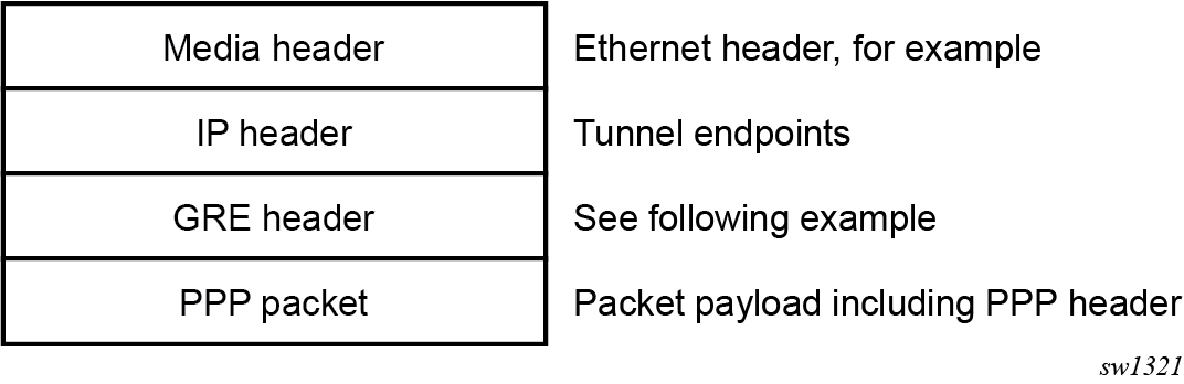
The following figure shows an example GRE header containing the Call ID of the peer for the session for which the GRE packet belongs.
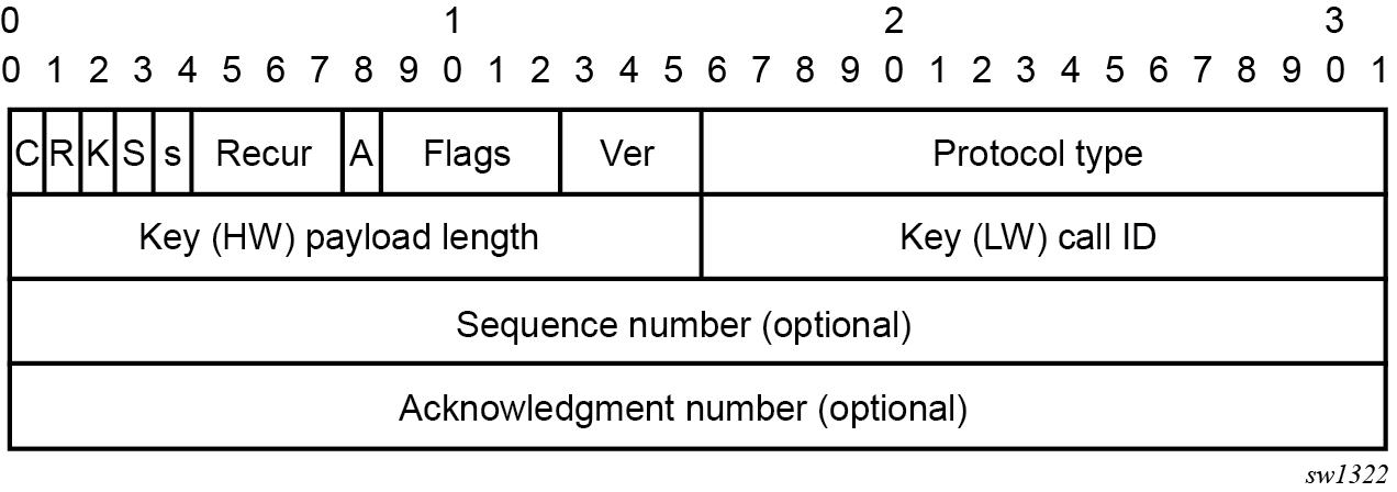
PPTP ALG operation
PPTP ALG is aware of the control session (Start Control Connection Request/Replay) and consequently it captures the Call ID field in all PPTP messages that carry that field. In addition to translating inside IP and TCP port, the PPTP ALG process data beyond the TCP header to extract the Call ID field and translate it inside of the Outgoing Call Request messages initiated from the inside of the NAT.
The GRE packets with corresponding Call IDs are translated through the NAT as follows:
The inside source IP address is replaced by the outside IP address and the opposite is true for traffic in the opposite direction. This is standard IP address translation technique. The key is to keep the outside IP address of the control packets and corresponding data packets (GRE tunnel) the same.
The Call-ID in the GRE packets in the direction of outside to inside is translated by the NAT according to the mappings that were created during session negotiation.
In addition, the following applies:
GRE packets are translated and passed through the NAT only if they can be matched to an existing PPTP call for which the mapping already exists.
Translation of the Call-IDs advertised by the PPTP server in the Outgoing Call Reply control message (this message is sent from the outside of the NAT to the inside) are not translated. Subsequently the Call ID in such messages are transparently passed through the NAT. There is no need to translate those Call IDs as their uniqueness between the two endpoints are guaranteed by the selection algorithm of the PPTP server. This can be thought of as destination TCP/UDP ports. They are not translated in the NAT. Instead only the source ports are translated.
PPTP session initiation in the outside to inside direction through the NAT is not supported.
Call-ID’s are allocated and used in the same fashion as the outside TCP/UDP ports (random with parity). They are taken from the same port range as ICMP ports.
The basic principle of PPTP NAT ALG is shown in NAT PPTP operation.

The scenario where multiple clients behind the NAT are terminated to the same PPTP server is shown in Merging of endpoints in NAT. In this case, it is possible that the source IP addresses of the two PPTP clients are mapped to the same outside address of the NAT. Because the endpoints of the GRE tunnel from the NAT to the PPTP server are the same for both PPTP clients (although their real source IP addresses are different), the NAT must ensure the uniqueness of the Call-IDs in the outbound data connection. This is where Call-ID translation in the NAT becomes crucial.
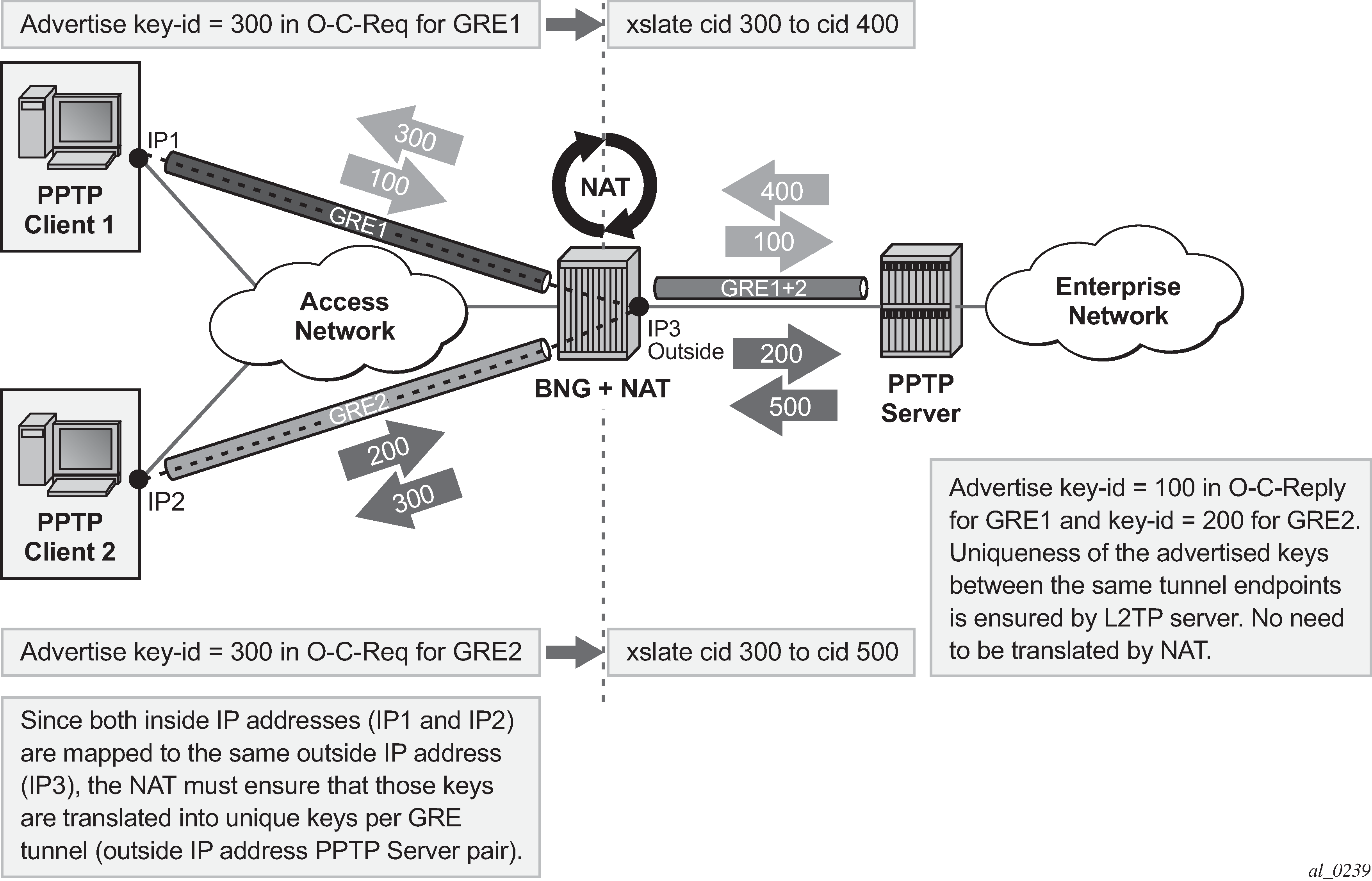
Multiple sessions initiated from the same PPTP client node
The routers supports a deployment scenario where multiple calls (or tunnels) are established from a single PPTP node within a single control connection. In this case, there is only one set of Start-Control-Connection-Req/Reply messages (one control channel) and multiple sets of Outgoing-Call-Req/Reply messages.
Selection of call IDs in NAT
Call-Id are taken from the same pool as the ICMP port ranges. Port-ranges and Call-IDs are both 16-bit values. Call-id selection mechanism is the same as the outside TCP/UDP port selection mechanism (random with parity).
Modifying active NAT prefix list or NAT classifier via CLI
Modifying active NAT prefix list or NAT classifier describes the outcome when the active NAT prefix list or NAT classifier is modified using CLI.
| Action | Outcome | Remarks | |
|---|---|---|---|
| L2-Aware | LSN | ||
CLI – Modifying prefix in the NAT prefix list |
Existing flows are always checked whether they comply with the NAT prefix list that is currently applied in the sub-profile for the subscriber. If the flows do not comply with the current NAT prefix list, they are cleared after 5 seconds. The new flows immediately start using the updated settings. |
Changing the prefix in the NAT prefix list internally re-subnets the outside IP address space. |
Nat-prefix list is used with multiple NAT policies in L2-Aware NAT and for downstream internal subnet in dNAT-only scenario for LSN. Prefix can be modified (added, removed, remapped) at any time in the NAT prefix list, while the NAT policy must be first shut down via CLI. |
CLI – Modifying the NAT classifier |
Existing flows are always checked whether they comply with the NAT classifier that is currently applied in the active NAT policy for the subscriber. If the flows do not comply with the current NAT classifier, they are cleared after 5 seconds. The new flows immediately start using the updated settings. |
Changing the NAT classifier has the same effect as in L2-Aware NAT; all existing flows using the NAT classifier are checked to see whether they comply with this classifier. |
The NAT classifier is used for dNAT. The NAT classifier is referenced in the NAT policy. |
CLI - Removing/adding NAT policy in nat-prefix-list |
Blocked |
Not Applicable |
— |
CLI - Removing/adding/replacing NAT policy in sub-profile |
Blocked |
Not Applicable |
— |
CLI - Removing/adding/replacing NAT prefix-list under the rtr/nat/inside/dnat-only |
Not Applicable |
Internally re-subnet, no effect on the flows |
— |
NAT logging
LSN logging is extremely important to the Service Providers (SP) who are required by the government agencies to track source of suspicious Internet activities back to the users that are hidden behind the LSN device.
The 7750 SR supports several modes of logging for LSN applications. Choosing the right logging model depends on the required scale, simplicity of deployment and granularity of the logged data.
For most purposes logging of allocation/de-allocation of outside port-blocks and outside IP address along with the corresponding LSN subscriber and inside service-id is sufficient.
In some cases, port-block based logging is not satisfactory and per flow logging is required.
Syslog/SNMP/local-file logging
The simplest form of LSN and L2-Aware NAT logging is via logging facility in the 7750 SR, commonly called logger. Each port-block allocation/de-allocation event is recorded and send to the system logging facility (logger). Such an event can be:
recorded in the system memory as part of regular logs
written to a local file
sent to an external server by a syslog facility
sent to a SNMT trap destination
In this mode of logging, all applications in the system share the same logger.
Syslog/SNMP/Local-File logging on LSN and NAT RADIUS-based logging are mutually exclusive.
Syslog/SNMP/local-file logging must be separately enabled for LSN and L2-Aware NAT in log even-control. The following displays relevant MIB events:
2012 tmnxNatPlBlockAllocationLsn
2013 tmnxNatPlBlockAllocationL2Aw
Filtering LSN events to system memory
In this example a single port-block [1884-1888] is allocated/de-allocated for the inside IP address 10.5.5.5 which is mapped to the outside IP address 198.51.100.1. Consequently the event is logged in the memory as.
2 2012/07/12 16:40:58.23 WEST MINOR: NAT #2012 Base NAT
"{2} Free 198.51.100.1 [1884-1888] -- vprn10 10.5.5.5 at 2012/07/12 16:40:58"

1 2012/07/12 16:39:55.15 WEST MINOR: NAT #2012 Base NAT
"{1} Map  198.51.100.1 [1884-1888] -- vprn10 10.5.5.5 at 2012/07/12 16:39:55"
When the needed LSN events are enabled for logging via event-control configuration, they can be logged to memory via standard log-id 99 or be filtered with a custom log-id, such as in this example (log-id 5):
Configuration:
*A:left-a20>config>log# info
----------------------------------------------
        filter 1
            default-action drop
            entry 1
                action forward
                match
                    application eq "nat"
                    numbr eq 2012
                exit
            exit
        exit
        event-control "nat" 2001 suppress
        event-control "nat" 2002 suppress
        event-control "nat" 2003 suppress
        event-control "nat" 2004 suppress
        event-control "nat" 2005 suppress
        event-control "nat" 2006 suppress
        event-control "nat" 2007 suppress
        event-control "nat" 2008 suppress
        event-control "nat" 2009 suppress
        event-control "nat" 2010 suppress
        event-control "nat" 2011 suppress
        event-control "nat" 2012 generate
        event-control "nat" 2014 suppress
        event-control "nat" 2015 suppress
        event-control "nat" 2017 suppress
        syslog 10
        exit
        log-id 5
            filter 1
            from main
            to memory
        exit
----------------------------------------------

*A:left-a20# show log event-control "nat"
=======================================================================
Log Events
=======================================================================
Application
 ID#    Event Name                       P   g/s     Logged     Dropped
-----------------------------------------------------------------------
   2001 tmnxNatPlL2AwBlockUsageHigh      WA  thr          0           0
   2002 tmnxNatIsaMemberSessionUsageHigh WA  thr          0           0
   2003 tmnxNatPlLsnMemberBlockUsageHigh WA  thr          0           0
   2007 tmnxNatL2AwSubIcmpPortUsageHigh  WA  thr          0           0
   2008 tmnxNatL2AwSubUdpPortUsageHigh   WA  thr          0           0
   2009 tmnxNatL2AwSubTcpPortUsageHigh   WA  thr          0           0
   2010 tmnxNatL2AwSubSessionUsageHigh   WA  thr          0           0
   2012 tmnxNatPlBlockAllocationLsn      MI  sup          0           0
   2013 tmnxNatPlBlockAllocationL2Aw     MI  sup          0           0
   2014 tmnxNatResourceProblemDetected   MI  thr          0           0
   2015 tmnxNatResourceProblemCause      MI  thr          0           0
   2016 tmnxNatPlAddrFree                MI  sup          0           0
   2017 tmnxNatPlLsnRedActiveChanged     WA  thr          0           0
   2018 tmnxNatPcpSrvStateChanged        MI  thr          0           0
   2020 tmnxNatMdaActive                 MI  thr          0           0
   2021 tmnxNatLsnSubBlksFree            MI  sup          0           0
   2022 tmnxNatDetPlcyChanged            MI  thr          0           0
   2023 tmnxNatMdaDetectsLoadSharingErr  MI  thr          0           0
   2024 tmnxNatIsaGrpOperStateChanged    MI  thr          0           0
   2025 tmnxNatIsaGrpIsDegraded          MI  thr          0           0
   2026 tmnxNatLsnSubIcmpPortUsgHigh     WA  thr          0           0
   2027 tmnxNatLsnSubUdpPortUsgHigh      WA  thr          0           0
   2028 tmnxNatLsnSubTcpPortUsgHigh      WA  thr          0           0
   2029 tmnxNatLsnSubSessionUsgHigh      WA  thr          0           0
   2030 tmnxNatInAddrPrefixBlksFree      MI  sup          0           0
   2031 tmnxNatFwd2EntryAdded            MI  sup          0           0
   2032 tmnxNatDetPlcyOperStateChanged   MI  thr          0           0
   2033 tmnxNatDetMapOperStateChanged    MI  thr          0           0
   2034 tmnxNatFwd2OperStateChanged      WA  thr          0           0
=======================================================================
The event description is shown below:
tmnxNatPlL2AwBlockUsageHigh
        The tmnxNatPlL2AwBlockUsageHigh notification is sent when
         the block usage of a Layer-2-Aware NAT address pool
         reaches its high watermark ('true')
         or when it reaches its low watermark again ('false').

tmnxNatIsaMemberSessionUsageHigh
        The tmnxNatIsaMemberSessionUsageHigh notification is sent when
         the session usage of a NAT ISA group member reaches its high
         watermark ('true') or when it reaches its low watermark
         again ('false').

tmnxNatPlLsnMemberBlockUsageHigh
        The tmnxNatPlLsnMemberBlockUsageHigh notification is sent when
         the block usage of a Large Scale NAT address pool
         reaches its high watermark ('true')
         or when it reaches its low watermark again ('false')
         on a particular member MDA of its ISA group.

tmnxNatLsnSubIcmpPortUsageHigh
        The tmnxNatLsnSubIcmpPortUsageHigh notification is sent when
         the ICMP port usage of a Large Scale NAT subscriber reaches its high
         watermark ('true') or when it reaches its low watermark
         again ('false').

tmnxNatLsnSubUdpPortUsageHigh
        The tmnxNatLsnSubUdpPortUsageHigh notification is sent when
         the UDP port usage of a Large Scale NAT subscriber reaches its high
         watermark ('true') or when it reaches its low watermark
         again ('false').

tmnxNatLsnSubTcpPortUsageHigh
        The tmnxNatLsnSubTcpPortUsageHigh notification is sent when
         the TCP port usage of a Large Scale NAT subscriber reaches its high
         watermark ('true') or when it reaches its low watermark
         again ('false').

tmnxNatL2AwSubIcmpPortUsageHigh
        The tmnxNatL2AwSubIcmpPortUsageHigh notification is sent when
         the ICMP port usage of a Layer-2-Aware NAT subscriber reaches its high
         watermark ('true') or when it reaches its low watermark
         again ('false').

tmnxNatL2AwSubUdpPortUsageHigh
        The tmnxNatL2AwSubUdpPortUsageHigh notification is sent when
         the UDP port usage of a Layer-2-Aware NAT subscriber reaches its high
         watermark ('true') or when it reaches its low watermark
         again ('false').

tmnxNatL2AwSubTcpPortUsageHigh
        The tmnxNatL2AwSubTcpPortUsageHigh notification is sent when
         the TCP port usage of a Layer-2-Aware NAT subscriber reaches its high
         watermark ('true') or when it reaches its low watermark
         again ('false').

tmnxNatL2AwSubSessionUsageHigh
        The tmnxNatL2AwSubSessionUsageHigh notification is sent when
         the session usage of a Layer-2-Aware NAT subscriber reaches its high
         watermark ('true') or when it reaches its low watermark
         again ('false').

tmnxNatLsnSubSessionUsageHigh
        The tmnxNatLsnSubSessionUsageHigh notification is sent when
         the session usage of a Large Scale NAT subscriber reaches its high
         watermark ('true') or when it reaches its low watermark
         again ('false').

tmnxNatPlBlockAllocationLsn
        The tmnxNatPlBlockAllocationLsn notification is sent when
         an outside IP address and a range of ports is allocated to
         a NAT subscriber associated with a Large Scale NAT (LSN) pool,
         and when this allocation expires.

tmnxNatPlBlockAllocationL2Aw
        The tmnxNatPlBlockAllocationL2Aw notification is sent when
         an outside IP address and a range of ports is allocated to
         a NAT subscriber associated with a Layer-2-Aware NAT pool,
         and when this allocation expires.

tmnxNatResourceProblemDetected
        The tmnxNatResourceProblemDetected notification is sent when
         the value of the object tmnxNatResourceProblem changes.

tmnxNatResourceProblemCause
        The tmnxNatResourceProblemCause notification is to describe the cause
         of a NAT resource problem.

tmnxNatPlAddrFree
        The tmnxNatPlAddrFree notification is sent when
         a range of outside IP addresses becomes free at once.

tmnxNatPlLsnRedActiveChanged
       The tmnxNatPlLsnRedActiveChanged notification is related to NAT Redundancy
       sent when the value of the object tmnxNatPlLsnRedActive changes. The cause is
       explained in the tmnxNatNotifyDescription which is a printable character
       string.

tmnxNatMdaActive
        The tmnxNatMdaActive notification is sent when
         the value of the object tmnxNatIsaMdaStatOperState changes from
         'primary' to any other value, or the other way around.
         The value 'primary' means that the MDA is active in the group.

tmnxNatLsnSubBlksFree
        The tmnxNatLsnSubBlksFree notification is sent when
         all port blocks allocated to a Large Scale NAT (LSN) subscriber
         are released.

         The NAT subscriber is identified with its subscriber ID
         tmnxNatNotifyLsnSubId.

         To further facilitate the identification of the NAT subscriber,
         its type tmnxNatNotifySubscriberType,
         inside IP address tmnxNatNotifyInsideAddr
         and inside virtual router instance tmnxNatNotifyInsideVRtrID
         are provided.

         The values of tmnxNatNotifyMdaChassisIndex, tmnxNatNotifyMdaCardSlotNum
         and tmnxNatNotifyMdaSlotNum identify the ISA MDA where the blocks were
         processed.

         All notifications of this type are sequentially numbered with
         the tmnxNatNotifyPlSeqNum.

         The value of tmnxNatNotifyNumber is the numerical identifier of the
         NAT policy used for this allocation; it can be used for correlation
         with the tmnxNatPlBlockAllocationLsn notification; the value zero
         means that this notification can be correlated with all the
         tmnxNatPlBlockAllocationLsn notifications of the subscriber.

tmnxNatDetPlcyChanged
        The tmnxNatDetPlcyChanged notification is sent when
         something changed in the Deterministic NAT map.

         [CAUSE] Such a change may be caused by a modification of the
        tmnxNatDetPlcyTable or the tmnxNatDetMapTable.

     [EFFECT] Traffic flows of one or more given subscribers, subject to NAT, may be
        assigned different outside IP address and/or outside port.

        [RECOVERY] Managers that rely on the offline representation of the
        Deterministic NAT map should get an updated copy.

tmnxNatMdaDetectsLoadSharingErr
        The tmnxNatMdaDetectsLoadSharingErr notification is sent
         periodically at most every 10 seconds while a NAT ISA MDA
         detects that it is receiving packets erroneously, due to
         incorrect load-balancing by the ingress IOM.

         The value of tmnxNatNotifyCounter is the incremental count of
         dropped packets since the previous notification sent by the same MDA.

         [CAUSE] The ingress IOM hardware does not support a particular
         NAT function's load-balancing, for example an IOM-2 does not
         support deterministic NAT.

         [EFFECT] The MDA drops all incorrectly load-balanced traffic.

         [RECOVERY] Upgrade the ingress IOM, or change the configuration.

tmnxNatIsaGrpOperStateChanged
        The tmnxNatIsaGrpOperStateChanged notification is sent when
         the value of the object tmnxNatIsaGrpOperState changes.

tmnxNatIsaGrpIsDegraded
        The tmnxNatIsaGrpIsDegraded notification is sent when
         the value of the object tmnxNatIsaGrpDegraded changes.

tmnxNatLsnSubIcmpPortUsgHigh
      The tmnxNatLsnSubIcmpPortUsgHigh notification is sent when
      the ICMP port usage of a Large Scale NAT subscriber reaches its high watermark
      ('true') or when it reaches its low watermark again ('false').

      The subscriber is identified with its inside IP address or prefix
      tmnxNatNotifyInsideAddr in the inside virtual router instance
      tmnxNatNotifyInsideVRtrID.

tmnxNatLsnSubUdpPortUsgHigh
        The tmnxNatLsnSubUdpPortUsgHigh notification is sent when
         the UDP port usage of a Large Scale NAT subscriber reaches its high
         watermark ('true') or when it reaches its low watermark
         again ('false').

         The subscriber is identified with its inside IP address or prefix
         tmnxNatNotifyInsideAddr in the inside virtual router instance
         tmnxNatNotifyInsideVRtrID.

tmnxNatLsnSubTcpPortUsgHigh
        The tmnxNatLsnSubTcpPortUsgHigh notification is sent when
         the TCP port usage of a Large Scale NAT subscriber reaches its high
         watermark ('true') or when it reaches its low watermark
         again ('false').

         The subscriber is identified with its inside IP address or prefix
          tmnxNatNotifyInsideAddr in the inside virtual router instance
          tmnxNatNotifyInsideVRtrID.

tmnxNatLsnSubSessionUsgHigh
        The tmnxNatLsnSubSessionUsgHigh notification is sent when
         the session usage of a Large Scale NAT subscriber reaches its high
         watermark ('true') or when it reaches its low watermark
         again ('false').

         The subscriber is identified with its inside IP address or prefix
         tmnxNatNotifyInsideAddr
         in the inside virtual router instance tmnxNatNotifyInsideVRtrID.

tmnxNatInAddrPrefixBlksFree
        The tmnxNatInAddrPrefixBlksFree notification is sent when
        all port blocks allocated to one or more subscribers
        associated with a particular set of inside addresses
        are released by this system.

        The type of subscriber(s) is indicated by tmnxNatNotifySubscriberType.

        The set of inside IP addresses is associated with the virtual
        router instance indicated by tmnxNatNotifyInsideVRtrID and is of the
         type indicated by tmnxNatNotifyInsideAddrType

        The set of inside IP addresses consists of the address prefix
        indicated with tmnxNatNotifyInsideAddr and tmnxNatNotifyInsideAddrPrefixLen
        unless these objects are empty and zero; if tmnxNatNotifyInsideAddr is empty
        and tmnxNatNotifyInsideAddrPrefixLen is zero, the set contains
        all IP addresses of the indicated type.

        The values of tmnxNatNotifyMdaChassisIndex, tmnxNatNotifyMdaCardSlotNum
        and tmnxNatNotifyMdaSlotNum identify the ISA MDA where the blocks were
        processed.

        All notifications of this type are sequentially numbered with
        the tmnxNatNotifyPlSeqNum.

        This type of notification is typically the consequence of one or
        more configuration changes; the nature of these changes is indicated
        in the tmnxNatNotifyDescription.

tmnxNatFwd2EntryAdded
        [CAUSE] The tmnxNatFwd2EntryAdded notification is sent when
         a row is added to or removed from the tmnxNatFwd2Table by other means
         than operations on the tmnxNatFwdAction;
         a conceptual row can be added to or removed from the table by operations on
         the tmnxNatFwdAction
         object group or otherwise, by means of the PCP protocol
         or automatically by the system, for example when a subscriber profile is
         changed.
         When the row is added, the value of the object
         tmnxNatNotifyTruthValue is 'true'; when the row is removed,
         it is 'false'.

         [EFFECT] The specified NAT subscriber can start receiving inbound
         traffic flows.
         [RECOVERY] No recovery required; this notification is the result
         of an operator or protocol action.

tmnxNatDetPlcyOperStateChanged
        [CAUSE] The tmnxNatDetPlcyOperStateChanged notification is sent when
         the value of the object tmnxNatDetPlcyOperState changes. The cause is
         explained in the tmnxNatNotifyDescription.
         tmnxNatDetMapOperStateChanged
         [CAUSE] The tmnxNatDetMapOperStateChanged notification is sent when
         the value of the object tmnxNatDetMapOperState changes. The cause is
         explained in the tmnxNatNotifyDescription.

tmnxNatFwd2OperStateChanged
      [CAUSE] The tmnxNatFwd2OperStateChanged notification is sent when
      the value of the object tmnxNatFwd2OperState changes. This
      is related to the state of the ISA MDA where the forwarding entry
      is located, or the availability of resources on that MDA.

      In the case of Layer-2-Aware NAT subscribers, the tmnxNatFwd2OperState
      is 'down' while the subscriber is not instantiated. This would typically
      be a transient situation.

      [EFFECT] The corresponding inward bound packets are dropped while the
      operational status is 'down'.

      [RECOVERY] If the ISA MDA reboots successfully, or another ISA MDA takes over,
      no recovery is required. If more resources become available on the ISA MDA, no
         recovery is required.
NAT logging to a local file
In this case, the destination of log-id 5 in the following example would be a local file instead of memory:
*A:left-a20>config>log# info
----------------------------------------------
        file-id 5
            description "nat logging"
            location cf1:
            rollover 15 retention 12
        exit

        log-id 5
            filter 1
            from main
            to file 5
        exit
The events are logged to a local file on the compact flash cf1 in a file under the /log directory.
SNMP trap logging
In case of SNMP logging to a remote node, the log destination should be set to SNMP destination. Allocation de-allocation of each port block triggers sending a SNMP trap message to the trap destination.
*A:left-a20>config>log# info
----------------------------------------------
       filter 1
            default-action drop
            entry 1
                action forward
                match
                    application eq "nat"
                    number eq 2012
                exit
            exit
        exit

        snmp-trap-group 6
            trap-target "nat" address 192.168.1.10 port 9001 snmpv2c notify-community "private"
        exit
        log-id 6
            filter 1
            from main
            to snmp
        exit
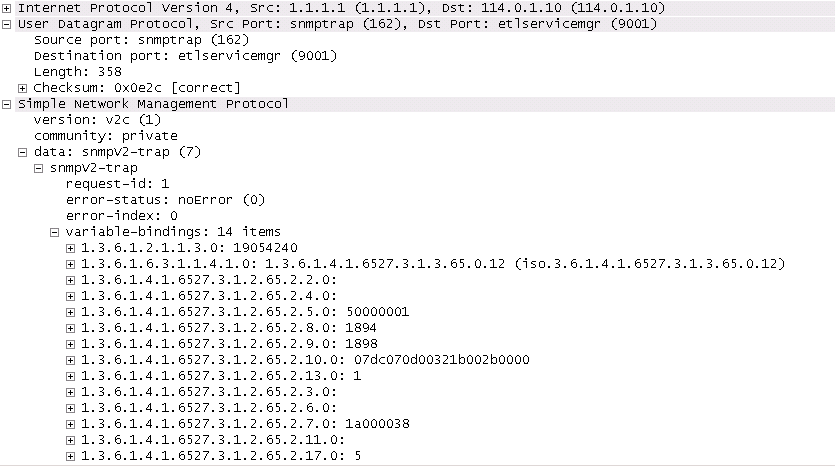
NAT syslog
NAT logs can be sent to a syslog remote facility. A separate syslog message is generated for every port-block allocation/de-allocation.
*A:left-a20>config>log#info
----------------------------------------------
...
        filter 1
            default-action drop
            entry 1
                action forward
                match
                    application eq "nat"
                    number eq 2012
                exit
            exit
        exit
        syslog 7
            address 192.168.1.10
        exit


        log-id 7
            filter 1
            from main
            to syslog 7
        exit

----------------------------------------------
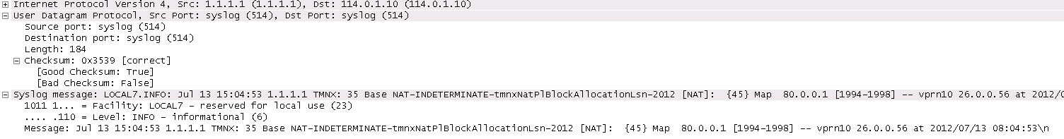
Severity level for this event can be changed via CLI:
*A:left-a20# configure log event-control "nat" 2012 generate
<severity-level>
cleared   indeterminate   critical   major   minor   warning
LSN RADIUS logging
LSN RADIUS logging (or accounting) is based on RADIUS accounting messages defined in RFC 2866. It requires a user to have RADIUS accounting infrastructure in place. For that reason, LSN RADIUS logging and LSN RADIUS accounting terms can be used interchangeably.
This mode of logging operation is introduced so that the shared logging infrastructure in 7750 SR can be offloaded by disabling syslog/SNMP/local-file LSN logging. The result is increased performance and higher scale, particularly in cases when multiple BB-ISA cards within the same system are deployed to perform aggregated LSN functions.
An additional benefit of LSN RADIUS logging over syslog/SNMP/local-file logging is reliable transport. Although RADIUS accounting relies on unreliable UDP transport, each accounting message from the RADIUS client must be acknowledged on the application level by the receiving end (accounting server).
Each port-block allocation or deallocation is reported to an external accounting (logging) server in the form of START, INTERIM-UPDATE, or STOP messages. The type of accounting messages generated depends on the mode of operation. The modes of operation are as follows:
-
START and STOP per port-block
An accounting START is generated when a new port-block for the LSN subscriber is allocated. Similarly, the accounting STOP is generated when the port-block is released. Each accounting START and STOP pair of messages that are triggered by port-block allocation or deallocation within the same subscriber have the same Acct-Multi-Session-Id (subscriber significant) but a different Acct-Session-Id (port-block significant). This mode of operation is enabled by the inclusion of Acct-Multi-Session-Id within the NAT accounting policy.
-
START and STOP per subscriber
An accounting START is generated when the first port block for the NAT subscriber is allocated. Each consecutive port-block allocation or deallocation triggers an INTERIM-UPDATE message with the same Acct-Session-Id (subscriber significant). The termination cause attribute in accounting STOP messages indicates the reason for port-block deallocation. Deallocation of the last port block for the LSN subscriber triggers an accounting STOP message. There is no Acct-Multi-Session-Id present in this mode of operation.
The accounting messages are generated and reported directly from the BB-ISA card, therefore bypassing accounting infrastructure residing on the Control Plane Module (CPM).
LSN RADIUS logging is enabled per NAT group. To achieve the required scale, each BB-ISA card in the NAT group with LSN RADIUS logging enabled runs a RADIUS client with its own unique source IP address. Accounting messages can be distributed to up to five accounting servers that can be accessed in round-robin fashion. Alternatively, in direct access mode, only one accounting server in the list is used. When this server fails, the next one in the list is used.
Perform the following steps to enable LSN RADIUS logging:
-
Configure the LSN RADIUS policy. The policy defines the following:
-
accounting destination
-
inclusion of RADIUS attributes that are sent in accounting messages to the destination
-
source IP addresses per BB-ISA card (RADIUS client) in the NAT group
Note: The accounting policy applies to both LSN and WLAN-GW. Some attributes are only applicable to NAT, some are only applicable WLAN-GW, and some are applicable to both. -
-
Apply this policy to the NAT group. This automatically enables RADIUS accounting on every BB-ISA card in the group, provided that each BB-ISA card has an IP address.
The following example shows the LSN RADIUS accounting policy configuration.
LSN RADIUS accounting policy configuration (MD-CLI)
[ex:/configure aaa radius isa-policy "1"]
A:admin@node-2# info detail
 ## apply-groups
 ## apply-groups-exclude
    description "RADIUS accounting policy for NAT"
 ## password
    nas-ip-address-origin system-ip
 ## python-policy
    accounting {
        include-attributes {
            acct-delay-time false
            acct-triggered-reason false
            called-station-id true
            calling-station-id false
            circuit-id false
            class false
            dhcp-options false
            dhcp-vendor-class-id false
            frame-counters true
            framed-ip-address true
            framed-ip-netmask false
            framed-ipv6-prefix false
            hardware-timestamp true
            ipv6-address false
            mac-address false
            multi-session-id true
            nas-identifier true
            nas-ip-address false
            nas-ipv6-address false
            nas-port false
            nas-port-id false
            nas-port-type false
            nat-inside-service-id true
            nat-outside-ip-address true
            nat-outside-service-id true
            nat-port-range-block true
            nat-subscriber-string false
            octet-counters true
            proxied-subscriber-data false
            release-reason true
            remote-id false
            rssi false
            session-time true
            subscriber-id false
            toserver-dhcp6-options false
            ue-creation-type false
            user-name true
            wlan-ssid-vlan false
            xconnect-tunnel-local-ipv6-address false
            xconnect-tunnel-remote-ipv6-address false
            xconnect-tunnel-service false
            xconnect-tunnel-type false
            xconnect-tunnel-home-address false
            millisecond-event-timestamp false
            credit-control-quota false
        }
    }

    ...

    servers {
        source-address-range 192.168.1.20
        timeout 5
        total-tries 3
        router-instance "Base"
        access-algorithm direct
        ipv6 {
            mtu 9000
         ## source-prefix
        }
        server 1 {
         ## apply-groups
         ## apply-groups-exclude
            admin-state disable
            ip-address 192.168.1.10
            secret "ZVo7IYMjSxbdW1ocPvLeFh5a8Xa1DVLOc2uzKVmGRnIKJo37JJjKleoTXIPkD7hQljmD3aC8ZdQOSlw=" hash2
            purpose {
                accounting {
                    udp-port 1813
                }
             ## authentication
             ## coa
            }
        }
    }
LSN RADIUS accounting policy configuration (classic CLI)
*A:node-2>config>aaa>isa-radius-plcy$ info detail
----------------------------------------------
            description "RADIUS accounting policy for NAT"
            nas-ip-address-origin system-ip
            no password
            no periodic-update
            user-name-format mac mac-format alu
            acct-include-attributes
                no acct-delay-time
                no acct-trigger-reason
                called-station-id
                no calling-station-id
                no circuit-id
                no class
                no credit-control-quota
                no dhcp-options
                no dhcp-vendor-class-id
                no dhcp6-options
                frame-counters
                framed-ip-addr
                no framed-ip-netmask
                no framed-ipv6-prefix
                hardware-timestamp
                inside-service-id
                no ipv6-address
                no mac-address
                no millisecond-event-timestamp
                multi-session-id
                nas-identifier
                no nas-ip-address
                no nas-ipv6-address
                no nas-port
                no nas-port-id
                no nas-port-type
                no nat-subscriber-string
                octet-counters
                outside-ip
                outside-service-id
                port-range-block
                release-reason
                no remote-id
                session-time
                no subscriber-data
                no subscriber-id
                no ue-creation-type
                user-name
                no wifi-rssi
                no wifi-ssid-vlan
                no xconnect-tunnel-home-address
                no xconnect-tunnel-local-ipv6-address
                no xconnect-tunnel-remote-ipv6-address
                no xconnect-tunnel-service
                no xconnect-tunnel-type
            exit

            ...

            servers
                access-algorithm direct
                retry 3
                router "Base"
                source-address-range 192.168.1.20
                timeout sec 5
                ipv6
                    mtu 9000
                    no source-prefix
                exit
                server 1 create
                    shutdown
                    accounting port 1813
                    no authentication
                    no coa
                    ip-address 192.168.1.10
                    secret "ZVo7IYMjSxbdW1ocPvLeFh5a8Xa1DVLOc2uzKVmGRnIKJo37JJjKleoTXIPkD7hQljmD3aC8ZdQOSlw=" hash2
                exit
            exit
----------------------------------------------
Use the following command to assign one unique IPv4 address to each BB-ISA card from the range of IPv4 addresses configured:
-
MD-CLI
configure aaa radius isa-policy servers source-address-range -
classic CLI
configure aaa isa-radius-policy servers source-address-range
The IP addresses are consecutively assigned to each BB-ISA, starting from the IP address configured by this command. The number of IP addresses allocated internally by the system corresponds to the number of BB-ISAs in the system.
Each BB-ISA is provisioned automatically with the first free IP address available, starting from the IP address that is configured using the source-address-range command. When a BB-ISA is removed from the system (or NAT group), it releases that IP address to be available to the next BB-ISA that comes online within the NAT group.
It is important to be mindful of the internally allocated IP addresses, because they are not explicitly configured in the system (other than the first IP address configured using the source-address-range command). However, those internally-assigned IP addresses can be seen using show commands in the routing table.
Use the following command to show route-table information.
show router route-tableThe following example shows there is one BB-ISA card in the NAT group 1. Its source IP address is 192.168.1.120.
NAT group with one BB-ISA card
===============================================================================================
Route Table (Router: Base)
===============================================================================================
Dest Prefix[Flags]  Type     Proto    Age         Pref  Next Hop[Interface Name]         Metric
-----------------------------------------------------------------------------------------------
80.0.0.1/32         Remote   NAT      02d18h24m   0     NAT outside: group 1 member 1    0
192.168.1.0/28      Local    Local    02d20h25m   0     radius                           0
192.168.1.20/32     Remote   NAT      00h38m29s   0     NAT outside: group 1 member 1    0
To communicate with IPv6 servers, provide a /64 source prefix for all ISAs and ESA VMs to use. Use the following command to configure this prefix:
-
MD-CLI
configure aaa radius isa-policy servers ipv6 source-prefix -
classic CLI
configure aaa isa-radius-policy servers ipv6 source-prefix
Each ISA or ESA uses one /128 address from this prefix as a source address when communicating with an IPv6 RADIUS server. Because this is a /64 prefix, there is no risk of the ISA or ESA VMs running out of allocated addresses or using addresses not assigned to them, as there is with IPv4.
There is no path MTU discovery when communicating with an IPv6 server. On IPv6 servers, only the originating host is allowed to fragment a packet. In this case, the host is the ISA or ESA VM. This means that any MTU applied to the IOM does not fragment the packet, as it does with IPv4. However, an MTU for IPv6 fragmentation can be configured manually. Use the following command to configure an MTU for IPv6 fragmentation:
-
MD-CLI
configure aaa radius isa-policy servers ipv6 mtu -
classic CLI
configure aaa isa-radius-policy servers ipv6 mtu
When the ISA or ESA VM generates a packet larger than the MTU, IPv6 fragmentation is applied to the packet.
It is possible to load-balance accounting messages over multiple logging servers by configuring the access-algorithm to round-robin mode. After the LSN RADIUS accounting policy is defined, it must be applied to a NAT group.
The following example shows a NAT group with an LSN RADIUS accounting policy applied to it.
NAT group with an LSN RADIUS accounting policy (MD-CLI)
*[ex:/configure isa nat-group 1]
A:admin@node-2# info
    admin-state enable
    radius-accounting-policy "nat-acct-basic"
    redundancy {
        active-mda-limit 1
    }
    mda 1/2 { }
NAT group with an LSN RADIUS accounting policy (classic CLI)
*A:node-2>config>isa>nat-group# info
----------------------------------------------
            active-mda-limit 1
            radius-accounting-policy "nat-acct-basic"
            mda 1/2
            no shutdown
The RADIUS accounting messages for when a Large Scale NAT44 subscriber has allocated two port blocks in a logging mode where accounting START or STOP is generated per port block are as follows.
Fri Jul 13 09:55:15 2012
        NAS-IP-Address = 10.1.1.1
        NAS-Identifier = "left-a20"
        NAS-Port = 37814272
        Acct-Status-Type = Start
        Acct-Multi-Session-Id = "500052cd2edcaeb97c2dad3d7c2dad3d"
        Acct-Session-Id = "500052cd2edcaeb96206475d7c2dad3d"
        Called-Station-Id = "00-00-00-00-01-01"
        User-Name = "LSN44@10.0.0.58"
        Alc-Serv-Id = 10
        Framed-IP-Address = 10.0.0.58
        Alc-Nat-Outside-Ip-Addr = 198.51.100.1
        Alc-Nat-Port-Range = "198.51.100.1 2024-2028 router base"
        Acct-Input-Packets = 0
        Acct-Output-Packets = 0
        Acct-Input-Octets = 0
        Acct-Output-Octets = 0
        Acct-Input-Gigawords = 0
        Acct-Output-Gigawords = 0
        Acct-Session-Time = 0
        Event-Timestamp = "Jul 13 2012 09:54:37 PDT"
        Acct-Unique-Session-Id = "21c45a8b92709fb8"
        Timestamp = 1342198515
        Request-Authenticator = Verified

Fri Jul 13 09:55:16 2012
        NAS-IP-Address = 10.1.1.1
        NAS-Identifier = "left-a20"
        NAS-Port = 37814272
        Acct-Status-Type = Start
        Acct-Multi-Session-Id = "500052cd2edcaeb97c2dad3d7c2dad3d"
        Acct-Session-Id = "500052cd2edcaeb9620647297c2dad3d"
        Called-Station-Id = "00-00-00-00-01-01"
        User-Name = "LSN44@10.0.0.58"
        Alc-Serv-Id = 10
        Framed-IP-Address = 10.0.0.58
        Alc-Nat-Outside-Ip-Addr = 198.51.100.1
        Alc-Nat-Port-Range = "198.51.100.1 2029-2033 router base"
        Acct-Input-Packets = 0
        Acct-Output-Packets = 5
        Acct-Input-Octets = 0
        Acct-Output-Octets = 370
        Acct-Input-Gigawords = 0
        Acct-Output-Gigawords = 0
        Acct-Session-Time = 1
        Event-Timestamp = "Jul 13 2012 09:54:38 PDT"
        Acct-Unique-Session-Id = "baf26e8a35e31020"
        Timestamp = 1342198516
        Request-Authenticator = Verified
The RADIUS accounting messages for when a Large Scale NAT44 subscriber has deallocated two port blocks in a logging mode where accounting START or STOP is generated per port block are as follows.
Fri Jul 13 09:56:18 2012
        NAS-IP-Address = 10.1.1.1
        NAS-Identifier = "left-a20"
        NAS-Port = 37814272
        Acct-Status-Type = Stop
        Acct-Multi-Session-Id = "500052cd2edcaeb97c2dad3d7c2dad3d"
        Acct-Session-Id = "500052cd2edcaeb96206475d7c2dad3d"
        Called-Station-Id = "00-00-00-00-01-01"
        User-Name = "LSN44@10.0.0.58"
        Alc-Serv-Id = 10
        Framed-IP-Address = 10.0.0.58
        Alc-Nat-Outside-Ip-Addr = 198.51.100.1
        Alc-Nat-Port-Range = "198.51.100.1 2024-2028 router base"
        Acct-Terminate-Cause = Port-Unneeded
        Acct-Input-Packets = 0
        Acct-Output-Packets = 25
        Acct-Input-Octets = 0
        Acct-Output-Octets = 1850
        Acct-Input-Gigawords = 0
        Acct-Output-Gigawords = 0
        Acct-Session-Time = 64
        Event-Timestamp = "Jul 13 2012 09:55:41 PDT"
        Acct-Unique-Session-Id = "21c45a8b92709fb8"
        Timestamp = 1342198578
        Request-Authenticator = Verified

Fri Jul 13 09:56:20 2012
        NAS-IP-Address = 10.1.1.1
        NAS-Identifier = "left-a20"
        NAS-Port = 37814272
        Acct-Status-Type = Stop
        Acct-Multi-Session-Id = "500052cd2edcaeb97c2dad3d7c2dad3d"
        Acct-Session-Id = "500052cd2edcaeb9620647297c2dad3d"
        Called-Station-Id = "00-00-00-00-01-01"
        User-Name = "LSN44@10.0.0.58"
        Alc-Serv-Id = 10
        Framed-IP-Address = 10.0.0.58
        Alc-Nat-Outside-Ip-Addr = 198.51.100.1
        Alc-Nat-Port-Range = "198.51.100.1 2029-2033 router base"
        Acct-Terminate-Cause = Host-Request
        Acct-Input-Packets = 0
        Acct-Output-Packets = 25
        Acct-Input-Octets = 0
        Acct-Output-Octets = 1850
        Acct-Input-Gigawords = 0
        Acct-Output-Gigawords = 0
        Acct-Session-Time = 65
        Event-Timestamp = "Jul 13 2012 09:55:42 PDT"
        Acct-Unique-Session-Id = "baf26e8a35e31020"
        Timestamp = 1342198580
        Request-Authenticator = Verified
Including the Acct-Multi-Session-Id attribute in the NAT accounting policy enables generating START and STOP messages for each allocation or deallocation of a port block within the subscriber. Otherwise, only the first and last port block for the subscriber would generate a pair of START and STOP messages. All port blocks in between would generate INTERIM-UPDATE messages.
The User-Name attribute in accounting messages is set to app-name@inside-ip-address. The app-name can be any of the following:
-
LSN44
-
DS-Lite
-
NAT64
Periodic RADIUS logging
Currently-allocated NAT resources (such as a public IP address and a port block for a NAT subscriber) can be periodically refreshed via Interim-Update (I-U) accounting messages. This functionality is enabled by the periodic RADIUS logging facility. Its primary purpose is to keep logging information preserved for long-lived sessions in environments where NAT logs are periodically and deliberately deleted from the service provider’s network. This is typically the case in countries where privacy laws impose a limit on the amount of time that the information about customer’s traffic can be retained/stored in service provider’s network.
Periodic RADIUS logging for NAT is enabled by the following command:
configure
    aaa
        isa-radius-policy <name> create
           [no] periodic-update interval <hours> [rate-limit <r>]
The configurable interval dictates the frequency of I-U messages that are generated for each currently allocated NAT resource (such as a public IP address and a port block).
By default, the I-U messages are sent in rapid succession for a subscriber without any intentional delay inserted by SR OS. For example, a NAT subscriber with 8 NAT policies, each configured with 40 port ranges generates 320 consecutive I-U messages at the expiration of the configured interval. This can create a surge in I-U message generation in cases where intervals are synchronized for multiple NAT subscribers. This can have adverse effects on the logging behavior. For example, the logging server can drop messages because of its inability to process the high rate of incoming I-U messages.
To prevent this, the rate of I-U message generation can be controlled by a rate-limit CLI parameter.
The periodic logging is applicable to both modes of RADIUS logging in NAT:
Acct-Multi-Session-Id AVP is enabled
In this case, accounting START/STOP messages are generated for each NAT resource (such as a public IP address and a port block) allocation/de-allocation. Acct-multi-session-id and acct-session-id messages in the periodic I-U messages for the currently allocated NAT resource are inherited from the acct START messages related to the same NAT resource.
-
Acct-Multi-Session-Id AVP is disabled
In this case, the acct START is generated for the first allocated NAT resource for the subscriber (a public IP address and a port block) and the acct STOP message is generated when the last NAT resource for the subscriber is released. All of the in-between port block allocations for the same subscriber trigger I-U messages with the same acct-session-id as the one contained in the acct START message. To differentiate between the port-block allocations, releases and updates within the I-U messages for the same NAT subscriber, the Alc-Acct-Triggered-Reason AVP is included in every periodic I-U message. Sending the Alc-Acct-Triggered-Reason AVP is configuration dependent (enabled in the isa-radius-policy>acct-include-attributes context).The supported values for Alc-Acct-Triggered-Reason AVP in I-U messages are:
-
Alc-Acct-Triggered-Reason=Nat-FREE (19) Generated when the port-block is released.
-
Alc-Acct-Triggered-Reason=Nat-MAP (20) Generated when the port-block is allocated.
-
Alc-Acct-Triggered-Reason = Nat-UPDATE (21) Generated during periodically scheduled I-U update.
The log for each port-block periodic update is carried in a separate I-U message.
-
Message pacing
Periodic I-U message output can be paced to avoid congestion at the logging server. Pacing is controlled by the rate-limit option of the periodic-update command. As an example, consider the following hypothetical case:
1 million NAT subscribers came up within 1hour (16,666 NAT-subs per minute).
-
On average, each NAT subscriber allocates two port blocks.
-
This means that 2 million logs are sent to the logging server.
-
If the rate-limit value is set to 100 (messages per second), on average it would take over 5 hours to send all those messages at the given rate.
-
In this case, it would be prudent to set the interval value to at least 6 hours, or increase the rate-limit value so there is no time overlap between the old and new logs.
In the case of an MS-ISA switchover or a NAT multi-chassis redundancy switchover, there is a chance that a large number of subscribers become active at approximately the same time on the newly active MS-ISA (or chassis). This causes a large number of logs to be sent in a relatively short amount of time, which may overwhelm the logging server. The rate-limit parameter is designed to help in such situations.
RADIUS logging and L2-Aware NAT
Logging of L2-Aware NAT is supported via accounting policy associated with the ESM subscriber (outside of NAT). In addition to ESM subscriber specific attributes, the NAT port-ranges and outside IP address (nat-port-range command in regular ESM accounting policy) are reported in the same accounting messages.
Fri Jul 13 11:57:38 2012
        Acct-Status-Type = Start
        NAS-IP-Address = 10.1.1.1
        User-Name = "l2-aware-nat"
        Framed-IP-Address = 198.51.100.100
        Framed-IP-Netmask = 255.255.255.0
        Class = 0x6c322d61776172652d636c737373
        Calling-Station-Id = "remote-l2-aware0"
        NAS-Identifier = "left-a20"
        Acct-Session-Id = "D896FF0000001150006F7C"
        Event-Timestamp = "Jul 13 2012 11:57:00 PDT"
        NAS-Port-Type = Ethernet
        NAS-Port-Id = "1/1/5:5.13"
        ADSL-Agent-Circuit-Id = "l2-aware-nat"
        ADSL-Agent-Remote-Id = "remote-l2-aware0"
        Alc-Subsc-ID-Str = "l2-aware-1"
        Alc-Subsc-Prof-Str = "l2-aware-nat"
        Alc-SLA-Prof-Str = "tp_sla_prem"
        Alc-Nat-Port-Range = "10.0.0.1 1024-1079 router base"
        Alc-Client-Hardware-Addr = "2001:db8:65:05:13:01"
        Acct-Delay-Time = 0
        Acct-Authentic = RADIUS
        Acct-Unique-Session-Id = "6bbbd5a110313b47"
        Timestamp = 1342205858
        Request-Authenticator = Verified
RADIUS accounting initiated by BB-ISA card is not supported for L2-Aware NAT.
Syslog/SNMP/Local-file logging can be enabled simultaneously with L2-Aware NAT RADIUS accounting (which is in this case regular ESM RADIUS accounting).
Integrated L2-Aware NAT RADIUS logging and BNG accounting
In L2-Aware NAT, the logging of NAT resources is integrated with ESM RADIUS accounting. The NAT-related resources reporting is described in Integrated ESM and NAT accounting .
Accounting START messages carry only the RADIUS Event-Timestamp (type 55), which correctly reflects the creation of the initial port block and outside IP address for L2-Aware NAT. The initial port block and outside IP address allocation in the ISA or ESA for a L2-Aware subscriber is triggered by the control plane (CPM) when the first session or host is created. This means that the initial port block and outside IP address creation in the ISA or ESA is not triggered by data traffic. However, data traffic triggers the creation of extend port blocks.
Interim-Updates and STOP accounting messages carry two timestamps. This is because the RADIUS accounting message is generated by the CPM at the time indicated by the Event-Timestamp, which may not accurately reflect the time of the extended port block allocation or de-allocation that occurs on ISA or ESA.
RADIUS Event-Timestamp (type 55) with a 1 second resolution
This timestamp is updated by the CPM with the time that the Interim-Update message is generated.
Nokia Alc-ISA-Event-Timestamp (type 86)
This is updated only when an event on the ISA or ESA occurs, for example, an extension port block is allocated or de-allocated. The format and resolution of this timestamp is the same as the format of the Event-Timestamp.
A summary of integrated ESM and NAT RADIUS logging is shown in Integrated ESM and NAT accounting . Only RADIUS attributes relevant to NAT are shown.
| ESM and NAT integrated RADIUS accounting/logging | |||
|---|---|---|---|
| Acct msg type | Queue-instance (Sla-profile instance) accounting |
Session or host accounting | Comments |
Start |
An Acct START message is generated for every SLA profile instantiation and every accounting START message contains NAT-related information carried in Alc-Nat-Port-Range (26.6527.121) which includes the outside IP address, newly allocated initial port block, outside router ID, and NAT policy ID. If there are multiple SLA profile instances per a NAT-enabled ESM subscriber, this information is repeated for all additional SLA profile instances. |
Acct START is generated for every new session or host of a NAT- enabled subscriber. This message carries:
The NAT related information is carried in the following RADIUS attribute: Alc-Nat-Port-Range(26.6527.121) This attribute includes the outside IP address, port blocks, outside router ID, and NAT policy. There is no distinction between NAT-enabled sessions or hosts and non NAT-enabled sessions of hosts (that is, non NAT-enabled sessions or hosts also carry NAT information) for a NAT enabled subscriber. |
The initial port block and outside IP address are always advertised in accounting START messages, regardless of whether there is a single session, host, multiple sessions, hosts per subscriber, or the sessions or hosts are NAT-enabled. |
Regular Interim-Update |
The message reports existing in-use NAT resources (the cumulative update) for each SLA profile instance: Alc-Nat-Port-Range (26.6527.121) The outside IP address, all existing port blocks, outside router ID, and NAT policy ID. Alc-ISA-Event-Timestamp(241.26.6527.86) The time of the last extended port block allocation or de-allocation on the ISA or ESA. Event-Timestamp (55) The time when the RADIUS message is generated on the CPM. This is repeated for all NAT- enabled sessions of an ESM subscriber. |
This message reports the existing in-use NAT resources (the cumulative update) for each session: Alc-Nat-Port-Range (26.6527.121) The outside IP address, all existing port blocks, outside router ID, and NAT policy. Alc-ISA-Event-Timestamp(241.26.6527.86) The time of the last extended port block allocation or de-allocation on the ISA or ESA. Event-Timestamp (55) The time when the RADIUS message is generated on the CPM This is repeated for all NAT-enabled sessions or hosts of an ESM subscriber. |
— |
Triggered Interim-Update |
This message carries differential updates tracking changes only for extended port blocks of the existing subscriber. The initial port-block is not advertised in the triggered Interim-Update but instead it is only advertised in the accounting START (map) or STOP (free) message. Alc-Nat-Port-Range (26.6527.121) The outside IP address, newly allocated or de-allocated extended port block, outside router ID, and NAT policy ID. Alc-Acct-Triggered-Reason (26.6527.163)
These are the reasons for this triggered Interim-Update message. An extended port block is allocated (MAP) or de-allocated (FREE). Alc-ISA-Event-Timestamp (241.26.6527.86) The time of the extended port block allocation or de-allocation on the ISA or ESA. Event-Timestamp (55) The time when the RADIUS message is generated on the CPM. This is repeated for each SLA-profile instance (queuing instance). |
This message carries differential updates tracking changes only for extended port blocks of the existing subscriber. The initial port block is never advertised in the triggered Interim-Update but is only advertised in accounting START (map) or STOP (free) message. Alc-Nat-Port-Range (26.6527.121) The outside IP address, newly allocated or de-allocated extended port block, outside router ID, and NAT policy ID. Alc-Acct-Triggered-Reason (26.6527.163)
The reason for this triggered Interim-Update message. An extended port block is allocated (MAP) or de-allocated (FREE). Alc-ISA-Event-Timestamp (241.26.6527.86) The time of the extended port block allocation or de-allocation on the ISA or ESA. Event-Timestamp (55) The time when the RADIUS message is generated on the CPM. This is repeated for all sessions or hosts of an ESM subscriber. |
If the last session of the subscriber is terminated, and at the same time this session has extended port blocks in use, two consecutive RADIUS accounting messages are sent (regardless of the accounting model):
A subscriber termination is infrequent event. |
Stop |
Accounting STOP messages are sent when an SLA profile instance (queuing-instance) is terminated (the last session associated with it is terminated). If the terminated SLA-profile instance (queuing instance) is the last for the subscriber, the accounting STOP message only carry the initial port block (and outside IP address). Any extended port blocks that were released are be reported in immediately preceding triggered Interim-Update message. If the terminated SLA-profile instance (queuing instance) is not the last for the subscriber, the accounting STOP message carries the initial port-block (and outside IP address) and any extended port blocks that are still allocated for the subscriber, but not used any more by this terminated SLA-profile instance. Alc-Nat-Port-Range (26.6527.121) The outside IP address, initial port block, outside router ID, and NAT policy ID. Alc-ISA-Event-Timestamp (241.26.6527.86) The time of the last extended port block allocation or de-allocation on the ISA or ESA. Event-Timestamp (55) The time when the RADIUS message is generated on the CPM. This information is generated for every SLA-profile instance (queuing instance) termination, meaning that the information is repeated if the subscriber has multiple SLA-profile instances. |
Accounting STOP message is sent when a session or host of a NAT enabled subscriber is terminated. If the terminated session of host is the last for the subscriber, the accounting STOP message carries only the initial port-block (and outside IP address). Any extended port blocks that were released are reported in immediately preceding triggered Interim-Update messages. If the terminated session or host is not the last for the subscriber, the accounting STOP message carries the initial port-block (and outside IP address) and any extended port blocks that are still allocated for the subscriber, but not used any more by this terminated session or host. Alc-Nat-Port-Range (26.6527.121) The outside IP address, initial port block, outside router ID, and NAT policy ID. Alc-ISA-Event-Timestamp (241.26.6527.86) The time of the last extended port block allocation or de-allocation on the ISA or ESA. Event-Timestamp (55) The time when the RADIUS message is generated on the CPM This information is generated upon termination of every session or host of an L2-Aware subscriber. |
Each accounting stream (START, I-U, STOP) is treated as a separate entity and it contains NAT information that can overlap with other accounting streams (for the queuing instance or a session) of the same subscriber. A complete NAT information is always conveyed in an accounting stream, for example, for every PB allocation a matching de-allocation can be found on the same stream. In other words, there are no known cases where a PB allocation is reported on one accounting stream, but de-allocation is reported on another. |
The following are examples showing only relevant NAT related attributes:
A session is created for a L2-Aware NAT subscriber. At the time of session instantiation, a RADIUS accounting START messages is generated.
     Alc-Nat-Port-Range = "192.168.20.2 2001-2024 router base l2-aware"
     Event-Timestamp = T1
The outside IP address 192.168.20.2 and initial port block [2001-2004] are allocated at time T1.
New extended port block is allocated. Differential data is carried in a triggered Interim-Update message.
     Alc-Nat-Port-Range = "192.168.20.2 3000-3023 router base l2-aware"
     Alc-Acct-Triggered-Reason = Nat-Map (20)
     Event-Timestamp = T3
     Alc-ISA-Event-Timestamp = T2
Only the new allocated port blocks are present in this update with the triggered reason Nat-Map (20).
This port block was allocated on ISA or ESA at time T2 which may be different than time T3 at which the Interim-Update is sent to the RADIUS server.
This difference may be small if there is no congestion in the system. It may be larger if there is congestion in the system while the notifications from the ISA or ESA are queued internally in the system waiting to be transported to the CPM which is backlogged. A reason for CPM backlog can be from a high volume of RADIUS messages that are sent to the RADIUS servers.
Periodic Interim-Update messages are triggered at regular intervals and carries cumulative (or absolute) data.
     Alc-Nat-Port-Range = "192.168.20.2 2001-2024, 3000-3023 router base l2-aware"
     Event-Timestamp = T4
     Alc-ISA-Event-Timestamp = T2
This update carries both previously allocated port blocks, the initial port block and the extended port block.
T4 in Event-Timestamp reflects the time when the message is generated, while the Alc-ISA-Event-Timestamp is unchanged from the previous update because no new event occurred on the ISA or ESA.
An existing extended port block is de-allocated. Differential data is carried in triggered Interim-Update message.
     Alc-Acct-Triggered-Reason = Nat-Free (19)
     Alc-Nat-Port-Range = "192.168.20.2 3000-3023 router base l2-aware"
     Event-Timestamp = T6
     Alc-ISA-Event-Timestamp = T5
Only the de-allocated port block is present in this update with the triggered reason NAT-Free (19).
This port block was de-allocated on ISA or ESA at time T5 which may be different than time T6 at which the Interim-Update is sent to the RADIUS server.
At session termination, a RADIUS accounting STOP message with initial port block is generated.
     Alc-Nat-Port-Range = "192.168.20.2 2001-2024 router base l2-aware"
     Event-Timestamp = T7
     Alc-ISA-Event-Timestamp = T5
This final update for the session carries the initial port block that is no longer used by the terminated session, host or queuing instance. Although this session is terminated, the initial port block can be used by another sessions still present under the same L2-Aware NAT subscriber.
T7 in Event-Timestamp reflects the time when the message is generated, while the Alc-ISA-Event-Timestamp is always the same as in the previous triggered accounting Interim-Update message.
Enabling RADIUS logging for L2-Aware NAT subscribers
This method of logging is enabled with a RADIUS accounting policy as follows:
[configure subscriber-mgmt radius-accounting-policy <name>]
     include-radius-attribute {
        nat-port-range true
        acct-triggered-reason true

     }
For session or host type accounting, the generation of periodic Interim-Update messages must be enabled as follows:
[configure subscriber-mgmt radius-accounting-policy <name>]
     session-accounting {
        interim-update true
     }
Timestamp interpretation
Extended port block functionality in L2-Aware NAT contains an additional time stamp into the logging framework. In addition to the standardized Event-Timestamp that is carried in every RADIUS accounting message, a NAT-related timestamp is included. This additional timestamp is introduced in the accounting stream after the first extended port block for the subscriber is allocated and then it is present in every accounting message in the stream. It represents the time of the last extended port block allocation or de-allocation as recoded by the ISA or ESA.
The two timestamps should be interpreted as the following:
The Standard Event-Timestamp (55) attribute records the time when the accounting message was generated on the CPM.
The Alc-ISA-Event-Timestamp (241.26.6527.86) attribute records the time of the last NAT related event (extended port block allocation or de-allocation).
For example, a periodic I-U message below indicates that at the time 1000, a subscriber has two ports blocks allocated: [2001-2024] and [3000-3023]. The last change related to extended port blocks was at time 500.
The following are Periodic Interim-Updates with the NAT-related attributes:
Alc-Nat-Port-Range = "192.168.20.2 2001-2024,3000-3023 router base l2-aware"
Event-Timestamp = 1000
Alc-ISA-Event-Timestamp = 500
In the following scenario where:
the extended port block [3000-3023] was released a few milliseconds before the previous periodic Interim-Update message was sent
notification from the ISA or ESA about this event has not reached the CPM in time for the event to be included in periodic Interim-Update
Then, a triggered Interim-Update would immediately follow the above periodic Interim-Update with relevant NAT related attributes:
Alc-Nat-Port-Range = "192.168.20.2 3000-3023 router base l2-aware"
Alc-Acct-Triggered-Reason = Nat-Free
Event-Timestamp = 1000
Alc-ISA-Event-Timestamp = 999
Both messages have the same Event-Timestamp of 1000 because the resolution of this timestamp is 1 second. However, the port block [3000-3023] was released at time 999 as indicated by the Alc-ISA-Event-Timestamp. This scenario is shown in Alc-ISA-Event-Timestamp.
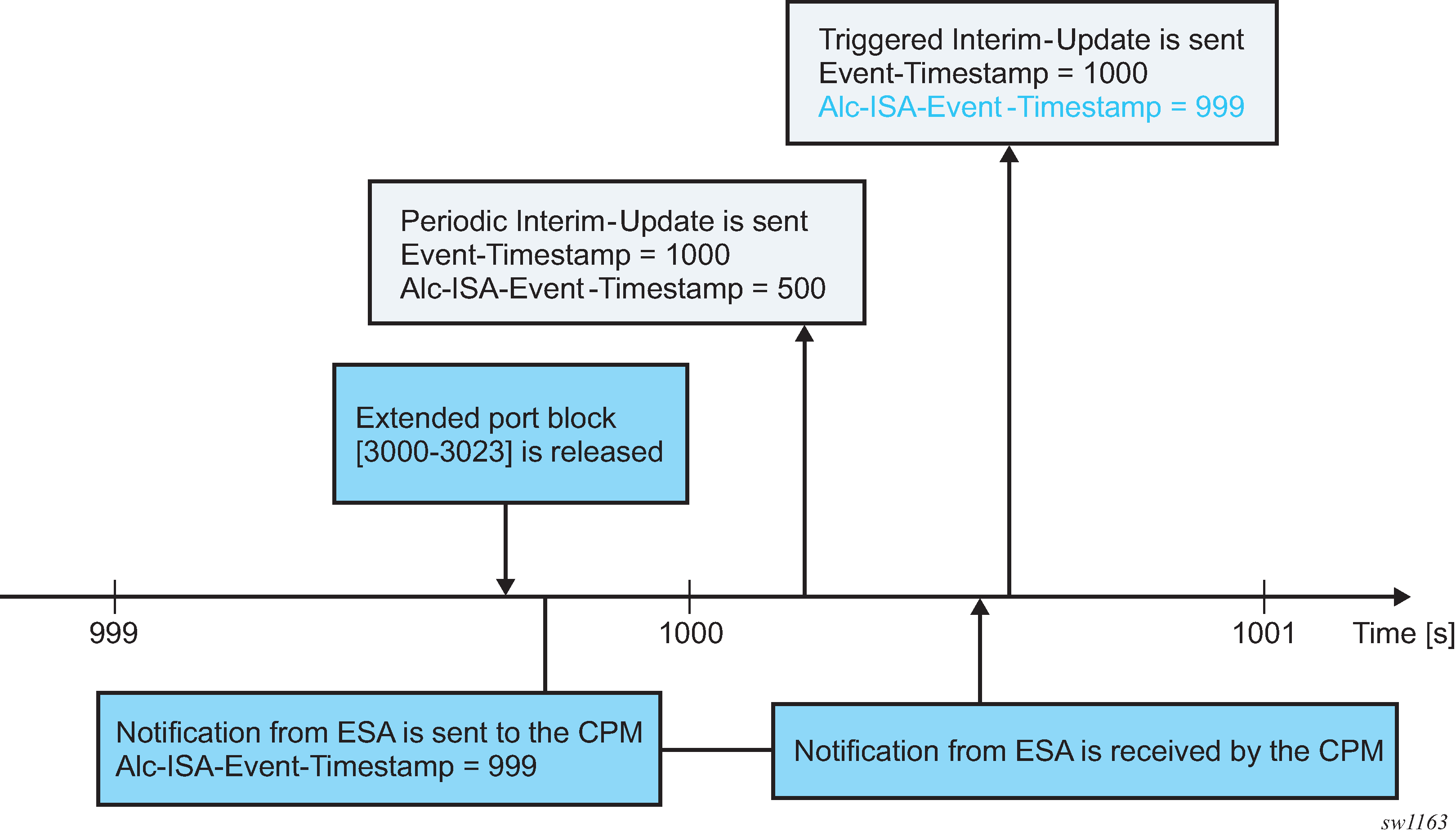
High logging rates
A system with on-demand port block allocations is dynamic with a possibility of generating a high volume of logs. Transporting NAT logs through ESM accounting relies on a generic RADIUS accounting infrastructure implemented in the SR which supports multiple RADIUS servers and failover mechanisms. In cases where the rate of accounting message exceeds the capacity of the entire accounting system, the queue of the accounting message toward the RADIUS servers in SR start to fill up. This can be caused by the internal condition in the SR by slow or even unresponsive RADIUS servers. Considering that NAT is only a contributor of the accounting messages in a larger accounting framework that includes ESM, the rate of the allocation and de-allocations of extended port blocks is internally limited. Although this does not prevent loss of accounting messages in the overloaded accounting system (for example, caused by slow RADIUS servers), it helps to reduce the chances that the system become overloaded.
Intra-chassis redundancy
Initial port blocks are preserved during an ISA or ESA switchover and are not affected by the switchover. However, extended port blocks are released during the switchover. Consequently, their release is reported in triggered Interim-Update messages.
LSN and L2-Aware NAT flow logging
LSN and L2-Aware NAT flow logging allows each BB-ISA card to export the creation and deletion of NAT flows to an external server. A NAT flow, or a Fully Qualified Flow, consists of the following parameters: inside IP, inside port, outside IP, outside port, foreign IP, foreign port, and protocol (UDP, TCP, ICMP).
Owner               : LSN-Host@10.10.10.101
Router              : 1
Policy              : mnp
FlowType            : UDP
Inside IP Addr      : 10.10.10.101
Inside Port         : 20001
Outside IP Addr     : 192.168.20.28
Outside Port        : 2001
Foreign IP Addr     : 192.168.5.4
Foreign Port        : 20001
Dest IP Addr        : 192.168.5.4
Nat Group           : 1
Nat Group Member    : 1
The foreign IP address is the original IPv4 destination address as received by NAT on the inside. The destination IP address is the translated foreign IP address if that destination NAT is active (the destination NAT translates the destination IPv4 address of the packet).
Additional information, such as the inside or outside service ID and subscriber string, can be added to a flow record.
Flow logging can be deployed as an alternative to port-range logging or can be complementary (providing a more granular log for offline reporting or compliance). Certain operators have legal and compliance requirements that require extremely detailed logs, created per flow, to be exportable from the NAT node.
Because the setup rate of new flows is excessive, logging to an internal facility (like compact flash) is not possible except in debugging mode (which must specify match criteria down to the inside IP and service level).
Flow logging can be enabled on a per-NAT policy basis and, consequently, it is initiated from each BB-ISA card. The flow records can be exported to an external collector in an IPFIX format or a syslog format, both of which use UDP as the transport protocol. These UDP streams are stateless because of the significant volume of transactions. However they do contain sequence numbers so packet loss can be identified. They egress the chassis at the fc nc.
IPFIX and SYSLOG flow logging are configured using respective flow logging policies (such as ipfix-export-policy and syslog-export-policy). Each flow logging policy supports two destinations (collectors). One ipfix-export-policy and one syslog-export-policy can be used simultaneously in any one NAT group.
IPFIX flow logging
IPFIX defines two different types of messages that are sent from the IPFIX exporter (SR OS NAT node). The first contains a template set which is an IPFIX message that defines fields for subsequent IPFIX messages but contains no actual data of its own. The second IPFIX message type contains data sets. Here, the data is passed using the previous template set message to define the fields. This means an IPFIX message is not passed as sets of TLV, but instead, data is encoded with a scheme defined through the template set message.
While an IPFIX message can contain both a template set and data set, the SR OS node sends template set messages periodically without any data, whereas the data set messages are sent on demand and as required. When IPFIX is used over UDP, the default retransmission frequency of the template set messages defaults to 10 minutes. The interval for retransmission is configurable in CLI with a minimum interval of one minute and a maximum interval of 10 minutes. When the exporter first initializes, or when a configuration change occurs, the template set is sent out three times, one second apart. Templates are sent before any data sets, assuming that the collector is enabled, so that an IPFIX collector can establish the data template set.
Although the UDP transport is unreliable, the IPFIX sequence number is a 32-bit number that contains the total number of IPFIX data records sent for the UDP transport session before the receipt of the new IPFIX message. The sequence number starts with 0 and rolls over when it reaches 4,294,967,268.
The default packet size is 1500 bytes unless another value has been defined in the configuration (the range is 512 bytes through 9212 bytes inclusively). Traffic is originated from a random high port to the collector on port 4739. Multiple create and delete flow records are stuffed into a single IPFIX packet (although the mappings created are not delayed) until stuffing an additional data record would exceed MTU or a timer expires. The timer is not configurable and is set to 250 milliseconds (that is, should any mapping occur, a packet is sent within 250 milliseconds of that mapping being created).
Each collector has a 50-packet buffering space. If, because of excessive logging, the buffering space becomes unavailable, new flows are denied and the deletion of flows is delayed until buffering space becomes available.
Two collector nodes can be defined in the same IPFIX export policy for redundancy purposes.
Template formats
The SR OS supports two data formats. Their selection is controlled through CLI:
configure
   service
      ipfix
         ipfix-export-policy <name> [create]
             template-format {format1|format2}
The difference between the two formats is related to the fields conveying information about the translated source IP addresses and ports (outside IP addresses and ports).
Format1 carries information about translated (outside) IP address in the sourceIPv4Address information element while in format2 this information element is replaced by the postNATSourceIPv4Address. Further, format1 does not convey any information about the translated source port (post-NAT) while a new information element postNAPTsourceTrasportPort is introduced in format2 to carry this information.
Both formats use proprietary information element AluNatSubString carrying the original source IP address, before NAT is performed.
The template and data sets are formatted according to RFC 5101, Specification of the IP Flow Information Export (IPFIX) Protocol for the Exchange of IP Traffic Flow Information.
Standardized data fields are defined in RFC 5102, Information Model for IP Flow Information Export, and in IANA registry https://www.iana.org/assignments/ipfix/ipfix.xhtml# ipfix-information-elements.
In addition to standardized data fields, IPFIX supports vendor-proprietary data fields which contains an Enterprise Number specific to each vendor.
The supported information elements and their description for each format is provided in IPFIX fields and formats . EN in IPFIX fields and formats stands for Enterprise Number (0 = IETF, 637 = Nokia) and IE-Id represents Information Element Identifier.
| Field | EN, IE-Id | Format 1 | Format 2 |
|---|---|---|---|
flowId |
0, 148 |
A unique (per-observation domain ID) ID for this flow. Used for tracking purposes only (opaque value). The flow ID in a create and a delete mapping record must be the same for a specific NAT mapping. |
A unique (per-observation domain ID) ID for this flow. Used for tracking purposes only (opaque value). The flow ID in a create and a delete mapping record must be the same for a specific NAT mapping. |
sourceIPv4Address |
0, 8 |
The outside (translated) IP address used in the NAT mapping. In format2, this is replaced by postNATSourceIPv4Address. |
N/A |
postNATSourceIPv4Address |
0, 255 |
N/A |
The outside (translated) IP address used in the NAT mapping. This replaces the sourceIPv4Address field from format1. |
destinationIPv4Address |
0, 12 |
The foreign or remote IP address used in the NAT mapping. |
The foreign or remote IP address used in the NAT mapping. |
sourceTransportPort |
0, 7 |
The outside (translated) source port used in the NAT mapping. |
This is the original source port (before NAT translation) on the inside |
postNAPTsourceTrasportPort |
0, 227 |
N/A |
The outside (translated) source port used in the NAT mapping |
destinationTransportPort |
0, 11 |
The destination port used in the NAT mapping. |
The destination port used in the NAT mapping. |
flowStartMilliseconds |
0, 152 |
The timestamp of when the flow was created (chassis NTP derived) in milliseconds from epoch. |
The timestamp of when the flow was created (chassis NTP derived) in milliseconds from epoch. |
flowEndMilliseconds |
0, 153 |
The timestamp of when the flow was destroyed (chassis NTP derived) in milliseconds from epoch. |
The timestamp of when the flow was destroyed (chassis NTP derived) in milliseconds from epoch. |
protocolIdentifier |
0, 4 |
Protocol (UDP, TCP, ICMP) |
Protocol (UDP, TCP, ICMP) |
flowEndReason |
0, 136 |
The reasons for flow termination. The following Flow End Reasons are supported:
|
The reasons for flow termination. The following Flow End Reasons are supported:
|
paddingOctets |
0, 210 |
Padding |
N/A |
aluInsideServiceId |
637, 91 |
The 16-bit service ID representing the inside service ID. This field is not applicable in L2-Aware NAT and is set to NULL in this case. |
The 16-bit service ID representing the inside service ID. This field is not applicable in L2-Aware NAT and is set to NULL in this case. |
aluOutsideServiceId |
637, 92 |
The 16-bit service ID representing the outside service ID. |
The 16-bit service ID representing the outside service ID. |
aluNatSubString |
637, 93 |
A variable 8B aligned string that represents the NAT subscriber construct (as currently used in the tools>dump>service>nat> session commands). The original IP source address, before NAT is performed is included in this string. For example: LSN-Host@10.10.10.101 |
A variable 8B aligned string that represents the NAT subscriber construct (as currently used in the tools>dump>service>nat> session commands). The original IP source address, before NAT is performed is included in this string. For example: LSN-Host@10.10.10.101 |
Template format 1 and format 2
Template format 1 and Template format 2 show information elements that are present in data sets during flow creation and deletion for the two formats. Each template set carries a unique template ID that is used to match the corresponding data set that carries the same ID in the set header (Set Id field).
| Flow creation template set | Flow deletion templates set | ||
|---|---|---|---|
| Description | Size (B) | Description | Size (B) |
flowId |
8 |
flowId |
8 |
sourceIPv4Address |
4 |
sourceIPv4Address |
4 |
destinationIPv4Address |
4 |
destinationIPv4Address |
4 |
sourceTransportPort |
2 |
sourceTransportPort |
2 |
destinationTransportPort |
2 |
destinationTransportPort |
2 |
flowStartMilliseconds |
8 |
flowEndMilliseconds |
8 |
protocolIdentifier |
1 |
protocolIdentifier |
1 |
paddingOctets |
1 |
flowEndReason |
1 |
aluInsideServiceID |
2 |
aluInsideServiceID |
2 |
aluOutsideServiceID |
2 |
aluOutsideServiceID |
2 |
aluNatSubString |
var |
aluNatSubString |
var |
| Flow creation template set | Flow deletion templates set | ||
|---|---|---|---|
| Description | Size (B) | Description | Size (B) |
flowId |
8 |
flowId |
8 |
postNATSourceIPv4Address |
4 |
postNATSourceIPv4Address |
4 |
destinationIPv4Address |
4 |
destinationIPv4Address |
4 |
sourceTransportPort |
2 |
sourceTransportPort |
2 |
postNAPTSourceTransportPort |
2 |
postNAPTSourceTransportPort |
2 |
destinationTransportPort |
2 |
destinationTransportPort |
2 |
flowStartMilliseconds |
8 |
protocolIdentifier |
1 |
protocolIdentifier |
1 |
flowEndReason |
1 |
paddingOctets |
1 |
flowEndMilliseconds |
8 |
aluInsideServiceID |
2 |
aluInsideServiceID |
2 |
aluOutsideServiceID |
2 |
aluOutsideServiceID |
2 |
aluNatSubString |
var |
aluNatSubString |
var |
Configuration example
Large Scale NAT44 Flow Logging with format2:
A collector node along with other local transport parameters must be defined through an IPFIX export policy.
*A:BNG1>config>service>ipfix# info detail
----------------------------------------------
            ipfix-export-policy "flow-logging" create
                no description
                template-format format2
                collector router "Base" ip 192.168.115.1 create
                    mtu 1500
                    source-address 192.0.2.2
                    template-refresh-timeout min 5
                    no shutdown
                exit
            exit
To export flow records using UDP stream, the BB-ISA card must be configured with an appropriate IPv4 address within a designated VPRN. This address (/32) acts as the source for sending all IPFIX records and is shared by all ISA.
After the IPFIX export policy is defined, it must be applied within the NAT policy:
*A:BNG1>config>service>nat#     info
----------------------------------------------
            nat-policy "mnp" create
                pool "mnp" router Base
                ipfix-export-policy "flow-logging"
            exit
Flow creation and flow deletion templates for format2, as captured in Wireshark, are shown in Format2 templates.
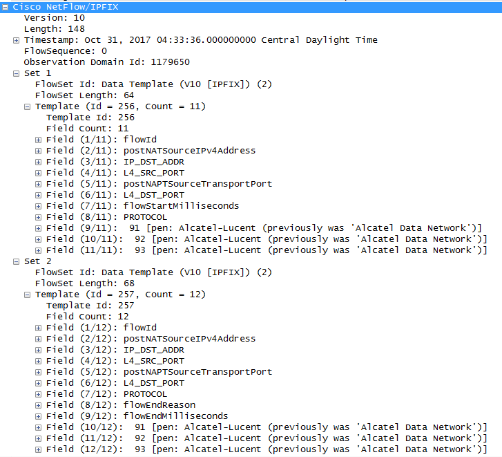
IPFIX flow creation data set, as captured in Wireshark, is shown in Flow creation data set.
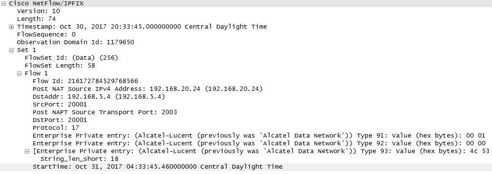
IPFIX flow destruction data set, as captured in Wireshark, is shown in Flow destruction.
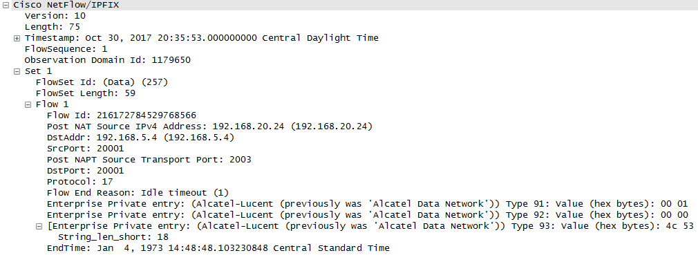
Syslog flow logging
The format of syslog messages for NAT flow logging in SR OS adheres to RFC 3164, The BSD Syslog Protocol:
<PRI> <HEADER><MSG>
where:
<PRI> (the ‟<” and ‟>” are included in the syslog message) is the configured facility*8+severity (as described in the 7450 ESS, 7750 SR, 7950 XRS, and VSR System Management Guide and RFC 3164).
<HEADER> defines the MMM DD HH:MM:SS <hostname>. Two characters always appear for the day (DD) field. Single-digit days are preceded with a space character. Time is recorded as local time (and not UTC). The time zone designator is not shown in this example, but each event has its own timestamp where the time-zone designator is shown.
<MSG> defines the <log-prefix>: <seq> <application [<subject>]: <message>\n
where:
<log-prefix> is an optional 32-character string of text (default = 'TMNX') as configured in the log-prefix command.
<seq> is the log event sequence number (always preceded by a colon and a space char).
The [<subject>] field may be empty resulting in []:
<message> display a custom message relevant to the log event.
\n is the standard ASCII new line character (hex 0A).
Syslog message fields for NAT flow logging shows the syslog message fields for NAT flow logging.
| Field name | Value | Comments |
|---|---|---|
PRI
|
|
|
Timestamps |
MMM DD HH:MM:SS |
|
<hostname> |
The IP address of the SR OS system that is generating the message. |
|
<log-prefix> |
Configurable. This can be used as a field to differentiate between the vendors. For example, NOK(ia) in log-prefix indicates that this is a log format from a Nokia node so the operator can apply parsing logic accordingly. |
|
<seq> |
Sequence numbers can be used for tracking if loss in transit occurs. |
|
<application> |
NAT |
The application that generated the log. |
[<subject>]: |
MDA ID |
The BB-ISA on which the event occurred. |
<message> |
This is a custom part with specific information related to the event itself. |
The message portion contains information relevant to the respective log event, even if this information is already repeated outside of the message (for example, timestamp). The fields in the message part are separated by a single whitespace for easier parsing and are placed in the order shown Message fields .
| Field name | Value | Presence | Comments |
|---|---|---|---|
NAT type |
LSN44 NAT64 |
M(andatory) |
|
Event name |
SADD SDEL |
M |
SADD – session added event SDEL – session deleted event |
Timestamp |
<TimeStamp>: <Year> <Mon> <Day> <hh:mm:ss:cs> <TZ>, Year is 4-digit, Mon is 3-letter abbreviation, TZ is a 1-5 character time-zone designator. |
M |
Because events can be combined in the same syslog message, each event is uniquely timestamped with the local time (not UTC), including the time zone designator. During daylight saving’s time (summer), the time zone designator is replaced by the DST designator, which is configurable. |
Protocol ID |
1, 6, 17 |
M |
ICMP, UDP, TCMP |
Inside router |
0 to 2147483650 |
M |
0 represents Base 1 to 2147483650 represents VPRNs |
Source IP address |
IPv4 address in LSN44 and IPv6 address in NAT64 |
M |
|
Source port or ICMP identifier |
0 to 65535 |
M |
|
Outside router |
0 to 2147483650 |
M |
|
Outside (post NAT) IP address |
IPv4 address |
M |
|
Outside (post NAT) port or ICMP identifier |
0 to 65535 |
M |
|
Foreign IP address |
IPv4 address |
O(ptional) |
This is the original destination IPv4 address. |
Foreign port or ICMP identifier |
0 to 65535 |
O |
|
Destination IP address |
IPv4 address |
O |
It represents the translated destination IP address. |
Nat-policy |
<name> |
O |
|
Sub-ID |
<sub-name> |
O |
‟-” if requested by the configuration (includes the sub-id statement) but the sub-aware NAT is not enabled. Otherwise, the sub-ID in the sub-aware NAT. |
Sequence numbers
Each syslog message contains a sequence number. The sequence numbers are independently generated by each BB-ISA per collector, and they are monotonically increased by 1. The MDA ID carried in the syslog message is used to differentiate between the overlapping sequence numbers generated by different BB-ISAs in the same NAT group.
Timestamp
Each flow creation or deletion event is timestamped individually using the local time in the system. The event timestamp (including the time-zone designator) is carried in the message part of the log. This timestamp is carried in addition to the syslog timestamp which is generated at the time of syslog message generation and carried in the <HEADER> part of the syslog messages.
Event aggregation
By default, flow logging events are transported to the collector as fast as they are generated. This does not imply that each event is transported individually, instead a few events can be still aggregated in a single message. However, this aggregation is not user controllable and it depends on the current condition in the system (events that are generated at approximately the same time).
To further optimize transport of logging events to the collector, the events can be aggregated in a controlled fashion. The flow logging events can be aggregated based on:
expiry of a configurable timer
transport message size (logs are collected until the size of the syslog message reaches the MTU size)
Whichever of the two conditions is met first triggers the generation of a syslog frame carrying multiple events. The separating character between the logs in a syslog message is ‟|” surrounded by a whitespace on each side.
<186>Jan 11 18:51:22 135.221.38.108 NOK: 47 NAT [MDA 1/1]: NAT44 SADD 2017 Jan 11 18:51:22:50 PST 6 0 10.10.10.1 3000 20 11.11.11.11 5000 12.12.12.12 8000 pol-name-1 sub-1 | NAT44 SADD 2017 Jan 11 18:51:22:60 PST 6 0 10.10.10.2 4000 20 11.11.11.11 6000 13.13.13.13 9000 pol-name-1 sub-1\n
Syslog transmission rate limit and overload conditions
The transmission rate of syslog messages can be limited by configuration. The rate limit is enforced in packets-per-seconds (pps). When the rate limit is exceeded, NAT flow logs are buffered. An overload condition is characterized by exhaustion of this buffer space. This condition can occur because of imposed rate limit or the software speed limit. Once the buffer space is exhausted, new flow creation is denied, and the teardown of the existing flows are delayed until the buffer space becomes available. Rate limit determines how fast the buffers are freed (by sending packets to the collector).
DS-Lite and NAT64 fragmentation
Overview
Fragmentation functionality is invoked when the size of a fragmentation eligible packet exceeds the size of the MTU of the egress interface or tunnel. Packets eligible for fragmentation are:
IPv4 packets or fragments with the DF bit in the IPv4 header cleared. Fragmentation can be performed on any routing node between the source and the destination of the packet.
IPv6 packets on the source node. Fragmentation of IPv6 packet on the transient routing nodes is not allowed.
The best practice is to avoid fragmentation in the network by ensuring adequate MTU size on the transient or source nodes. Drawbacks of the fragmentation are:
increased processing and memory demands to the network nodes (especially during reassembly process)
increased byte overhead
increased latency
Fragmentation can be particularly deceiving in a tunneled environment whereby the tunnel encapsulation adds extra overhead to the original packet. This extra overhead could tip the size of the resulting packet over the egress MTU limit.
Fragmentation could be one solution in cases where the restriction in the mtu size on the packet’s path from source to the destination cannot be avoided. Routers support IPv6 fragmentation in DS-Lite and NAT64 with some enriched capabilities, such as optional packet IPv6 fragmentation even in cases where DF-bit in corresponding IPv4 packet is set.
In general, the lengths of the fragments must be chosen such that resulting fragment packets fit within the MTU of the path to the packets destinations.
In downstream direction fragmentation can be implemented in two ways:
IPV4 packet can be fragmented in the carrier IOM before it reaches ISA for any NAT function.
IPv6 packet can be fragmented in the ISA, after the IPv4 packet is IPv6 encapsulated in DS-Lite or IPv6 translated in NAT64.
In upstream direction, IPv4 packets can be fragmented after they are decapsulated in DS-Lite or translated in NAT64. The fragmentation occurs in the IOM.
IPv6 fragmentation in DS-Lite
In the downstream direction, the IPv6 packet carrying IPv4 packet (IPv4-in-IPv6) is fragmented in the ISA in case the configured DS-Lite tunnel-mtu is smaller than the size of the IPv4 packet that is to be tunneled inside of the IPv6 packet. The maximum IPv6 fragment size is 48bytes larger than the value set by the tunnel-mtu. The additional 48 bytes is added by the IPv6 header fields: 40 bytes for the basic IPv6 header plus 8 bytes for extended IPv6 fragmentation header. NAT implementation in the routers does not insert any extension IPv6 headers other than fragmentation header.
DS-Lite shows DS-Lite IPv6 fragmentation.

If the IPv4 packet is larger than the value set by the tunnel-mtu, the fragmentation action depends on the configuration options and the DF bit setting in the header of the received IPv4 header:
The IPv4 packet can be dropped regardless of the DF bit setting. IPv6 fragmentation is disabled.
The IPv4 packet can be encapsulated in IPv6 packet and then the IPv6 can be fragmented regardless of the DF bit setting in the IPv4 tunneled packet. The IPv6 fragment payload is limited to the value set by the tunnel-mtu.
The IPv4 packet can be encapsulated in IPv6 packet and then the IPv6 can be fragmented only if the DF bit is cleared. The IPv6 fragment payload is limited to the value set by the tunnel-mtu.
If the IPv4 packet is dropped because of fragmentation not being allowed, an ICMPv4 Datagram Too Big message is returned to the source. This message carries the information about the size of the MTU that is supported, by notifying the source to reduce its MTU size to the requested value (tunnel-mtu).
The maximum number of supported fragments per IPv6 packet is 8. Considering that the minimum standard based size for IPv6 packet is 1280 bytes, 8 fragments is enough to cover jumbo Ethernet frames.
configure
   [router] | [service vprn]
        nat
          inside
             dual-stack-lite
address <IPv6 Addr>
                   tunnel-mtu bytes
                  ip-fragmentation {disabled | fragment-ipv6 | fragment-ipv6-unless-ipv4-df-set}
NAT64
Downstream fragmentation in NAT64 works in similar fashion. The difference between DS-Lite is that in NAT64 the configured ipv6-mtu represents the mtu size of the IPv6 packet (as opposed to payload of the IPv6 tunnel in DS-Lite). In addition, IPv4 packet in NAT64 is not tunneled but instead IPv4 or IPv6 headers are translated. Consequently, the fragmented IPv6 packet size is 28 bytes larger than the translated IPv4 packet 20 bytes difference in basic IP header sizes (40-bytes IPv6 header versus a 20-byte IPv4 header) plus 8 bytes for extended fragmentation IPv6 header. The only extended IPv6 header that NAT64 generates is the fragmentation header.
If the IPv4 packet is dropped because of the fragmentation not being allowed, the returned ICMP message contains MTU size of ipv6-mtu minus 28 bytes.
Otherwise the fragmentation options are the same as in DS-Lite.
configure
   [router] | [service vprn]
        nat
          inside
             nat64
                ipv6-mtu bytes
            ip-fragmentation {disabled | fragment-ipv6 | fragment-ipv6-unless-ipv4-df-set}
DS-Lite reassembly
In a tunneled environment such as DS-Lite, a fragmented packet must be reassembled in the end node before it is decapsulated. DS-Lite reassembly is implemented in-line, which means that the reassembly function runs in the same MS-ISA where native DS-Lite processing occurs. The presence of the Fragment Extension header in the IPv6 header signals the need for reassembly for all traffic destined for the AFTR in the upstream direction.
Fragments of a frame can be buffered for up to two seconds in an MS-ISA to wait for all the fragments of the original frame to arrive can be reassembled.
DS-Lite reassembly is performed only in the upstream direction.
Interpreting fragmentation statistics
Fragmentation statistics in DS-Lite can be observed by issuing the following command:
show isa nat-group <grp-id> mda <slot-id/mda-id> statistics
The command output displays only relevant DS-Lite fragmentation counters are shown. The remaining counters are removed from the output for easier reading.
show isa nat-group 1 mda 1/2 statistics
===============================================================================
ISA NAT Group 1 MDA 1/2
===============================================================================
--snip--
too many fragments for IP packet                        : 0
too many fragmented packets                             : 0
too many fragment holes                                 : 0
too many frags buffered                                 : 0
fragment list expired                                   : 0
Reassembly Failures                                     : 0
Fragments RX DSL                                        : 0
Fragments RX DORMANT                                    : 0
Fragments TX DSL                                        : 0
Fragments TX DORMANT                                    : 0
Fragments RX OUT                                        : 0
Fragments TX OUT                                        : 0
too many frag. lists for flow                           : 0
frag. list cleanup in progress                          : 0
--snip--
===============================================================================
To interpret these counters, familiarity with the following terms in the context of fragmentation is required:
-
packet
An IP packet that is split into fragments (multiple frames) because of its original size being larger than the MTU configured on any node servicing this packet.
-
fragment
A fragment comprises the frames that make up a packet. Multiple fragments (frames on the wire) are eventually reassembled into the original packet.
-
fragment list
MS-ISA maintains a list of fragments belonging to a single packet. Each list represents a single fragmented packet and the list contains multiple fragments.
-
fragment hole
A hole refers to a fragment or a group of consecutive fragments in a fragment list. Fragments of a packet are sequentially numbered from first to last and they must be reassembled in the same order in which they are fragmented. For example, if a packet contains 9 fragments but only fragments [1,3,5,9] are received by MS-ISA, then there are 3 holes in this list [2],[3,4],[6,7,8].
-
flow
This is identified by 5 tuple <src IP, dst IP, src Port, dst Port, protocol>. Flows can have many packets and each packet of a flow can be fragmented.
Counter names and descriptions describes counter names.
| Counter name | Description |
|---|---|
too many fragments for IP packet |
This counter increments if there are more than 20 fragments of a received single packet (the maximum number of fragments per packet is 20). In this case, all fragments of the packet are dropped. |
too many fragmented packets |
This counter increases if the maximum number of fragmented packets per MS-ISA is reached. See the MS-ISA Scaling Guides for the maximum number of fragmented packets per MS-ISA (specifically, the max num of frag lists parameter). |
too many fragment holes |
This counter increments if there are more than 11 holes tracked for a single packet. In this case, all fragments are be dropped. |
too many frags buffered |
This counter increases if the maximum number of fragments that can be stored on MS-ISA is reached. |
fragment list expired |
This counter increases if all fragments of single packets are not received within two seconds. In this case, all fragments of this packet are dropped. |
lists for flow |
This counter increases when more than five fragmented packets per flow are being maintained simultaneously in MS-ISA. In this case, the fragments of the sixth packets are dropped. |
Reassembly Failures |
This counter increases when the reassembly of a packets (when all fragments are received) failed. This can attributed to the size of the first DS-Lite IPv6 fragment is smaller than 1280B, or the total reassembled packet is too big (greater than 9212B). |
Fragments RX DSL |
This counter increments only when a DS-Lite packet/fragment is received in the upstream direction that contains an IPv4 fragment. In other words, this counter is relevant only to IPv4 fragments inside of the DS-Lite packet/fragment that is received from the subscriber, and is not affected by DS-Lite fragments. |
Fragments TX DSL |
This counter increments only in case that DS-Lite packet/fragment sent in the downstream direction contains an encapsulated IPv4 fragment (which is received from the public side). In other words, this counter is relevant only to IPv4 fragments inside of the DS-Lite packet/fragment that is sent toward the subscriber, and is not affected by DS-Lite fragments. |
Fragments RX OUT |
This counter increments when an IPv4 fragment is received in the downstream direction, toward the subscriber. |
Fragments TX OUT |
This counter increments when an IPv4 fragment is transmitted in the upstream direction (public side). |
Support for small first fragments
RFC 8200, Internet Protocol, Version 6 (IPv6) Specification, recommends the minimum MTU size in IPv6 should be 1280 bytes. However, some devices sourcing IPv6 traffic do not follow this recommendation and fragments packets to a size smaller than 1280 bytes. To accommodate these devices, the DS-Lite implementation in SR OS can process first fragments (with the fragment offset equaling 0 in the IPv6 fragmentation header) that are smaller than 1280 bytes. The SR OS can reassemble such packets in the upstream direction, as well as fragment them in the downstream direction.
Upstream reassembly with small first IPv6 fragments less than 1280 bytes
This functionality is disabled by default, and can be explicitly enabled by configuring the min-first-fragment-size-rx command under the DS-lite configuration.
Classic CLI:
config
   router / service vprn
      nat
         inside
               dual-stack-lite
                         address  <AFTR IPv6 address>
                              min-first-fragment-size-rx <512..1280>
MD-CLI:
configure {
   router {
      nat {
         inside {
            large-scale {
               dual-stack-lite {
                  endpoint <AFTR IPv6 address> {
                     min-first-fragment-size-rx <512..1280>
                  }
               }
            }
         }
      }
   }
}
Downstream fragmentation with small first IPv6 fragment
In the downstream direction, the existing tunnel-mtu command is used to set the size of the frames in the downstream direction.
Classic CLI:
config
   router / service vprn
      nat
         inside
               dual-stack-lite
                         address  <AFTR IPv6 address>
                              tunnel-mtu <464..1280>
MD-CLI:
configure {
   router {
      nat {
         inside {
            large-scale {
               dual-stack-lite {
                  endpoint <AFTR IPv6 address> {
                     tunnel-mtu <464..1280>
                  }
               }
            }
         }
      }
   }
}
The tunnel-mtu value represents the size of the IPv4 payload which is encapsulated in the IPv6 packet with an additional 48-byte header. These IPv6 packets can then be fragmented when fragmentation is enabled.
Histogram
The histogram tools command shows several summarized distributions:
ports and subscribers
The distribution of outside ports in a NAT pool for an aggregate number of subscribers. The output of the histogram command can reveal the number of subscribers in a pool that are heavy port users, or it can reveal the average number of ports used by most subscribers
port blocks and subscribers in a NAT pool
The distribution of port blocks in an L2-aware NAT pool for an aggregate number of subscribers. The output of the histogram command can reveal how subscribers are using port blocks in the aggregate.
extended port blocks and outside IP addresses in a NAT pool
The distribution of extended port blocks in NAT pool in relation to an aggregate number of outside IP addresses. The output of the histogram command can reveal how extended port blocks are distributed over IP addresses in an aggregate. This is applicable only for a L2-aware NAT pool with extended port blocks enabled, or a deterministic LSN pool.
The operator can use the displayed information to adjust the port block size per subscriber, the amount of port blocks per subscriber, or see port usage trends over time. Consequently, the operator can adjust the configuration as the port demand per subscriber increases or decreases over time. For example, an operator may find that the port usage in a pools increased over a period of time. Accordingly, the operator can plan to increase the number of ports per port block.
The output of the histogram command is described in the following examples:
ports and subscribers per NAT pool (L2-aware or LSN)
The output is organized in port buckets with the number of subscribers in each bucket.
show router nat pool <name> histogram ports
  - ports bucket-size <size> num-buckets <number>
 <size>               : [1..65536]
 <number>             : [2..50]

show router nat pool "pool-1" histogram ports bucket-size 200 num-buckets 10
===============================================================================
Usage histogram NAT pool "pool-1" router "Base"
===============================================================================
Num-ports   Sub-TCP    Sub-UDP    Sub-ICMP
-------------------------------------------------------------------------------
1-199       17170      0          0
200-399     8707       0          0
400-599     2406       0          0
600-799     635        0          0
800-999     322        0          0
1000-1199   0          0          0
1200-1399   0          0          0
1400-1599   0          0          0
1600-1799   0          0          0
1800-       0          0          0
-------------------------------------------------------------------------------
No. of entries: 10
===============================================================================
port blocks and subscribers per NAT pool (L2-aware and LSN)
The output is organized by the increasing number of port blocks in a NAT pool with the number of subscribers using the number of port blocks indicated in each line.
show router nat pool <name> histogram port-blocks

show router nat pool "l2a" histogram port-blocks
===============================================================================
Usage histogram NAT pool "l2a" router "Base" port blocks per subscriber
===============================================================================
Num port-blocks      Num subscribers
-------------------------------------------------------------------------------
1                    17398
2                    8550
3                    2352
4                    940
5                    0
6                    0
7                    0
8                    0
9                    0
10                   0
-------------------------------------------------------------------------------
No. of entries: 10
===============================================================================
extended port blocks in a NAT pool and outside IP addresses (L2-aware NAT and deterministic LSN)
The output is organized in extended port-block buckets in a NAT pool with the number of outside IP addresses in each bucket.
show router nat pool demo histogram extended-port-blocks-per-ip
  - extended-port-blocks-per-ip bucket-size <size> num-buckets <number>
 <size>               : [1..65536]
 <number>             : [2..50]
show router nat pool "l2a" histogram extended-port-blocks-per-ip bucket-size 1 num-buckets 10
===============================================================================
Usage histogram NAT pool "l2a" router "Base" extended port blocks per IP address
===============================================================================
Num extended-port-blocks      Num IP addresses
-------------------------------------------------------------------------------
-                             -
1-1                           1039
2-2                           6182
3-3                           777
4-4                           194
5-5                           0
6-6                           0
7-7                           0
8-8                           0
9-                            0
-------------------------------------------------------------------------------
No. of entries: 10
===============================================================================
The output of each command can be periodically exported to an external destination with the cron command. The following displays an example of the output:
/configure system
   script-control {
      script "nat_histogram" owner ‟TiMOSCLI” {
        admin-state enable
        location "ftp://*:*@138.203.8.62/nat-histogram.txt"
      }
   script-policy "dump_nat_histogram" owner ‟TiMOS CLI” {
        admin-state enable
        results "ftp://*:*@138.203.8.62/nat_histogram_results.txt"
        script {
          name "nat_histogram"
        }
   }
  }
   cron {
      schedule "nat_histogram_schedule" owner ‟TiMOS CLI” {
        admin-state enable
        interval 600
        script-policy {
          name "dump_nat_histogram"
        }
      }
The nat-histogram.txt file contains the command execution line. For example:
tools dump nat histogram router 4 pool "deterministic" bucket-size 10 num-buckets 10
This command is executed every 10 minutes (600 seconds) and the output of the command is written into a set of files on an external TFP server as displayed in the following example:
 [root@ftp]# ls nat_histogram_results.txt*
    nat_histogram_results.txt_20130117-153548.out
    nat_histogram_results.txt_20130117-153648.out
    nat_histogram_results.txt_20130117-153748.out
    nat_histogram_results.txt_20130117-153848.out
    nat_histogram_results.txt_20130117-153948.out
    nat_histogram_results.txt_20130117-154048.out
    [root@ftp]#
NAT redundancy
NAT ISA redundancy helps protect against Integrated Service Adapter (ISA) failures. This protection mechanism relies on the CPM maintaining configuration copy of each ISA. In case that an ISA fails, the CPM restores the NAT configuration from the failed ISA to the remaining ISAs in the system. NAT configuration copy of each ISA, as maintained by CPM, is concerned with configuration of outside IP address and port forwards on each ISA. However, CPM does not maintain the state of dynamically created translations on each ISA. This causes interruption in traffic until the translation are re-initiated by the devices behind the NAT.
Two modes of operation are supported:
Active-Standby
In this mode of operation, any number of standby ISAs can be allocated for protection purposes. When there are no failures in the router, standby ISAs are idle, in a state ready to accept traffic from failed ISA. Mapping between the failed ISA and the standby ISA is always 1:1. This means that one standby ISA entirely replaces one failed ISA. In this respect, NAT bandwidth from the failed ISA is reserved and restored upon failure. This model is shown in Active-Standby intra-chassis redundancy model.
Figure 34. Active-Standby intra-chassis redundancy model 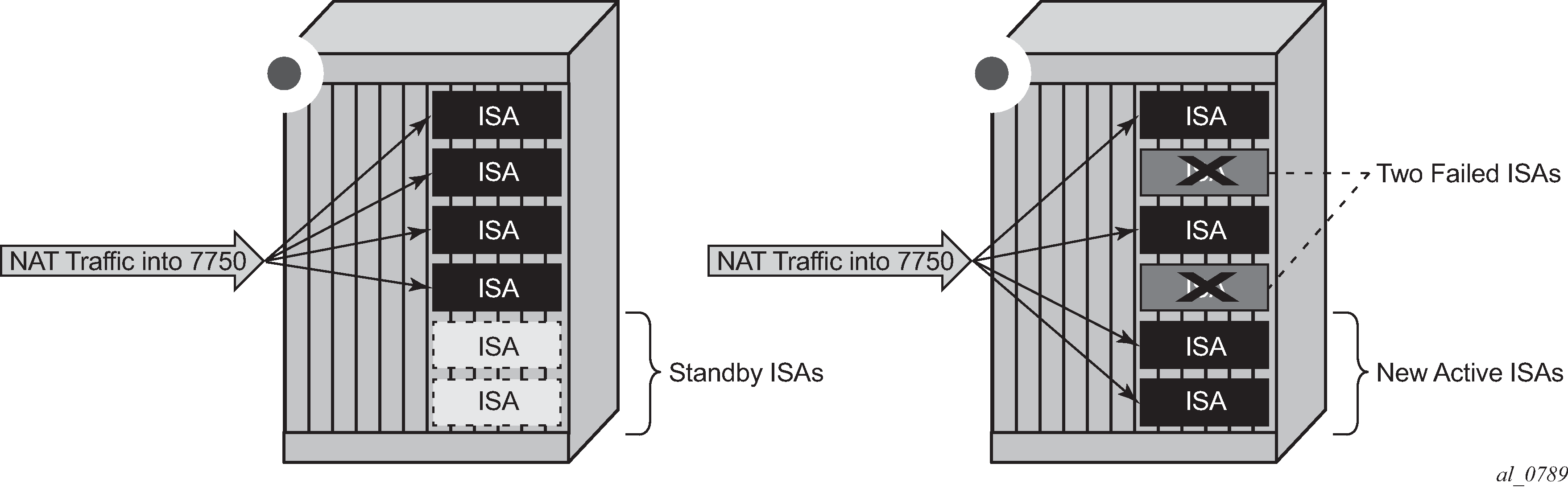
Active-Active
In this mode all ISAs in the system are active. When an ISA fails, its load is distributed across the remaining active ISA. In this mode of operation there is no bandwidth reservation across active ISA. Each ISA can operate at full speed at any time. However, memory resources necessary to setup new translations from the failed ISAs are reserved. The reserved resources are:
subscribers (inside IPv4 addresses for LSN44, IPv6 prefixes for DS-Lite/NAT64 and L2-Aware subscriber)
outside IPv4 addresses
outside port-ranges
By reserving memory resources it can be assured that failed traffic can be recovered by remaining ISAs, potentially with some bandwidth reduction in case that remaining ISAs operated at full or close to full speed before the failure occurred. Active-active ISA redundancy model is shown in Active-Active intra-chassis redundancy model.
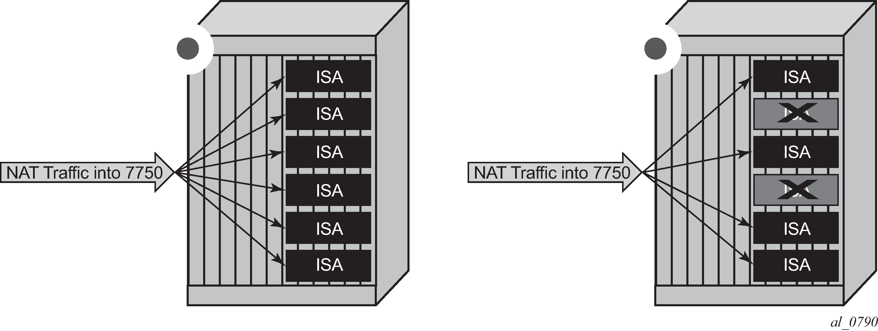
In case of an ISA failure, the member-id of the member ISA that failed is contained in the FREE log. This info is used to find the corresponding MAP log which also contains the member-id field.
In case of RADIUS logging, CPM summarization trap is generated (because RADIUS log is sent from the ISA – which is failed).
NAT stateless dual-homing
Multi-chassis stateless NAT redundancy is based on a switchover of the NAT pool that can assume active (master) or standby state. The inside/outside routes that attract traffic to the NAT pool are always advertised from the active node (the node on which the pool is active).
This dual-homed redundancy based on the pool mastership state works well in scenarios where each inside routing context is configured with a single NAT policy (NAT’d traffic within this inside routing context is mapped to a single NAT pool).
However, in cases where the inside traffic is mapped to multiple pools (with deterministic NAT and in case when multiple NAT policies are configured per inside routing context), the basic per pool multi-chassis redundancy mode can cause the inside traffic within the same routing instance to fail because some pools referenced from the routing instance may be active on one node while other pools may be active on the other node.
Imagine a case where traffic ingressing the same inside routing instance is mapped as follows (this mapping can be achieved via filters):
Source ip-address A → Pool 1 (nat-policy 1) active on Node 1
Source ip-address B → Pool 2 (nat-policy 2) active on Node 2
Traffic for the same destination is normally attracted only to one NAT node (the destination route is advertised only from a single NAT node). Assume that this node is Node 1 in the example. After the traffic arrives to the NAT node, it is mapped to the corresponding pool according to the mapping criteria (routing based or filter based). But if active pools are not co-located, traffic destined for the pool that is active on the neighboring node would fail. In our example traffic from the source ip-address B would arrive to the Node 1, while the corresponding Pool 2 is inactive on that node. Consequently the traffic forwarding would fail.
To remedy this situation, a group of pools targeted from the same inside routing context must be active on the same node simultaneously. In other words, the active pools referenced from the same inside routing instance must be co-located. This group of pools is referred to as Pool Fate Sharing Group (PFSG). The PFSG is defined as a group of all NAT pools referenced by inside routing contexts whereby at least one of those pools is shared by those inside routing contexts. This is shown in Active-Standby intra-chassis redundancy model.
Even though only Pool 2 is shared between subscribers in VRF 1 and VRF 2, the remaining pools in VRF 1 and VRF 2 must be made part of PFSG 1 as well.
This ensures that the inside traffic is always mapped to pools that are active in a single box.
Pool fate sharing group shows the pool fate sharing group.
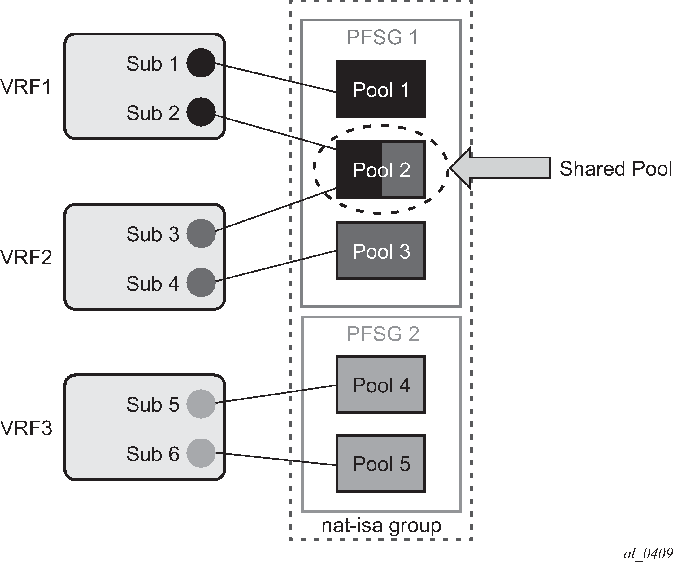
There is always one lead pool in PFSG. The Lead pool is the only pool that is exporting/monitoring routes. Other pools in the PFSG are referencing the lead pool and they inherit its (activity) state. If any of the pools in PFSG fails, all the pools in the PFSG switch the activity, or in another words they share the fate of the lead pool (active/standby/disabled).
There is one lead pool per PFSG per node in a dual-homed environment. Each lead pool in a PFSG has its own export route that must match the monitoring route of the lead pool in the corresponding PFSG on the peering node.
PFSG is implicitly enabled by configuring multiple pools to follow the same lead pool.
Configuration considerations
Attracting traffic to the active NAT node (from inside and outside) is based on the routing.
On the outside, the active pool address range is advertised. On the inside, the destination prefix or steering route (in case of filter based diversion to the NAT function) is advertised by the node with the active pool.
The advertisement of the routes is driven by the activity of the pools in the pool fate sharing group:
configure
   router/service vprn
      nat
         outside
            pool <name>
               redundancy
                  export <ip-prefix/length>
                  monitor <ip-prefix/length>[no] shutdown
                  follow router  <rtr-id> pool <master-pool>
For example:
router/service vprn
    nat
        outside
          pool "nat0-pool" nat-group 1 type large-scale create
             port-reservation ports 252
            redundancy
               follow router 500 pool "nat500-pool"
            exit
           address-range 192.168.12.0 192.168.12.10 create
           exit
            no shutdown
          exit
       exit
     exit
A pool can be one of the following:
a leading pool (configure export- and monitor-route and put in no shutdown)
A following pool (configure follow)
Both sets of options are therefore mutually exclusive.
A leading pool redundancy is only enabled when the redundancy node is in no shutdown. For a following pool, the administrate has no effect, and the redundancy is only enabled when the leading pool is enabled.
Before a lead pool is enabled, consistency checks are performed to make sure that PFSG is properly configured and that the all pools in the PFSG belong to the same NAT ISA group. PFSG is implicitly enabled by configuring multiple pools to follow the same lead pool. Adding or removing pools from the fate-share-group is only possible when the leading pool is disabled.
For example in the case shown in Consistency check, the consistency check would fail because pool 1 is not part of the PFSG 1 (where it should be).
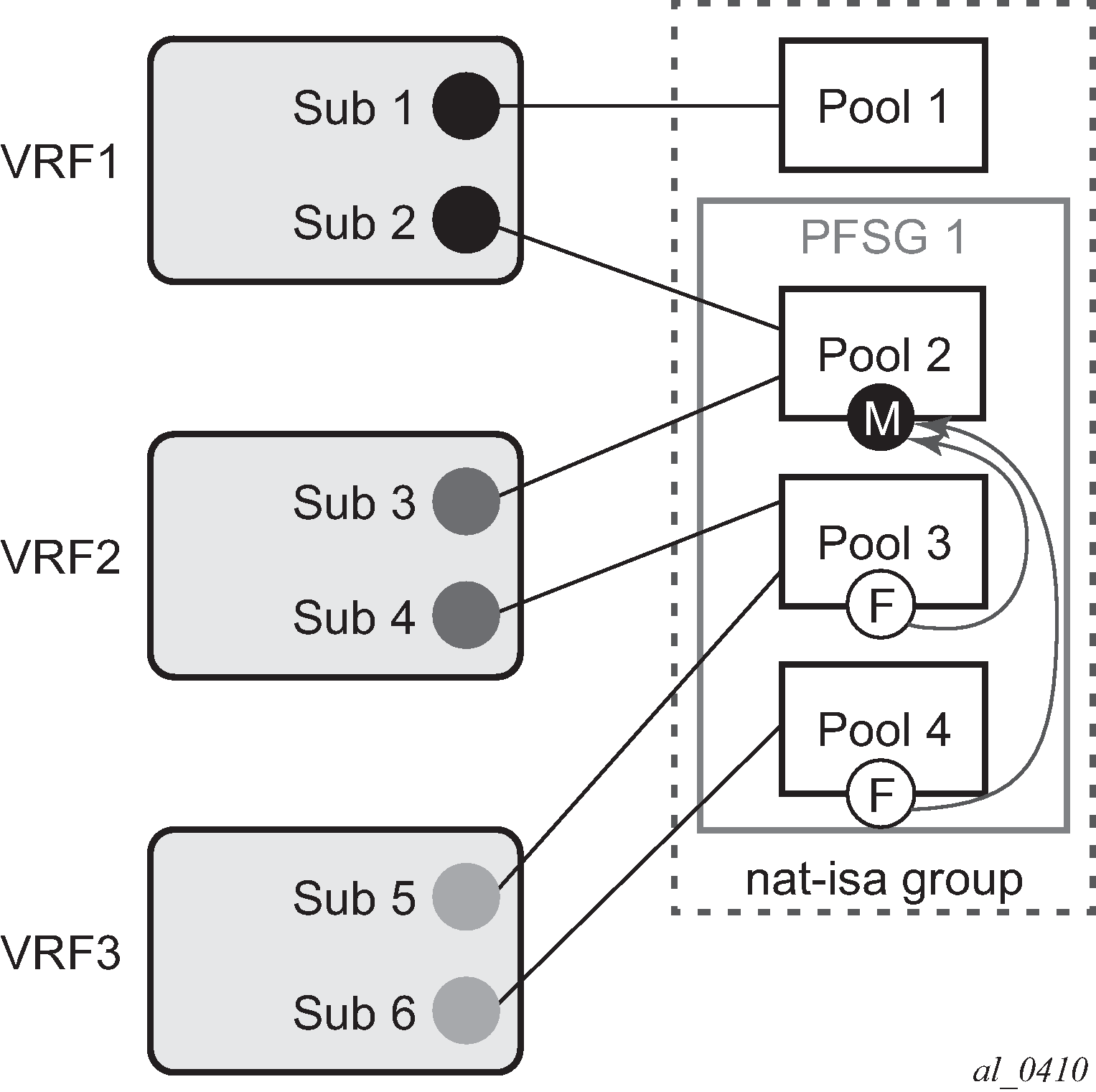
Troubleshooting commands
The following command displays the state of the leading pool (dual-homing section toward the bottom of the command output):
*A:Dut-B# show router 500 nat pool "nat500-pool"
===============================================================================
NAT Pool nat500-pool
===============================================================================
Description                           : (Not Specified)
ISA NAT Group                         : 1
Pool type                             : largeScale
Admin state                           : inService
Mode                                  : auto (napt)
Port forwarding dyn blocks reserved   : 0
Port forwarding range                 : 1 - 1023
Port reservation                      : 2300 blocks
Block usage High Watermark (%)        : (Not Specified)
Block usage Low Watermark (%)         : (Not Specified)
Subscriber limit per IP address       : 65535
Active                                : true
Deterministic port reservation        : (Not Specified)
Last Mgmt Change                      : 02/17/2014 09:41:43
===============================================================================
===============================================================================
NAT address ranges of pool nat500-pool
===============================================================================
Range                                                          Drain Num-blk
-------------------------------------------------------------------------------
192.168.1.0 - 192.168.1.255                                          0
-------------------------------------------------------------------------------
No. of ranges: 1
===============================================================================

===============================================================================
NAT members of pool nat500-pool ISA NAT group 1
===============================================================================
Member                                                        Block-Usage-% Hi
-------------------------------------------------------------------------------
1                                                             < 1           N
2                                                             < 1           N
3                                                             < 1           N
4                                                             < 1           N
5                                                             < 1           N
6                                                             < 1           N
-------------------------------------------------------------------------------
No. of members: 6
===============================================================================
===============================================================================
Dual-Homing
===============================================================================
Type                                  : Leader
Export route                          : 10.0.0.3/32
Monitor route                         : 10.0.0.2/32
Admin state                           : inService
Dual-Homing State                     : Active
===============================================================================
===============================================================================
Dual-Homing fate-share-group
===============================================================================
Router         Pool                                                   Type
-------------------------------------------------------------------------------
Base           nat0-pool                                              Follower
vprn500        nat500-pool                                            Leader
vprn501        nat501-pool                                            Follower
vprn502        nat502-pool                                            Follower
-------------------------------------------------------------------------------
No. of pools: 4
===============================================================================
The following command displays the state of the follower pool (dual-homing section toward the bottom of the command output):
*A:Dut-B# show router 501 nat pool "nat501-pool"
===============================================================================
NAT Pool nat501-pool
===============================================================================
Description                           : (Not Specified)
ISA NAT Group                         : 1
Pool type                             : largeScale
Admin state                           : inService
Mode                                  : auto (napt)
Port forwarding dyn blocks reserved   : 0
Port forwarding range                 : 1 - 1023
Port reservation                      : 2300 blocks
Block usage High Watermark (%)        : (Not Specified)
Block usage Low Watermark (%)         : (Not Specified)
Subscriber limit per IP address       : 65535
Active                                : true
Deterministic port reservation        : (Not Specified)
Last Mgmt Change                      : 02/17/2014 09:41:43
===============================================================================
===============================================================================
NAT address ranges of pool nat501-pool
===============================================================================
Range                                                          Drain Num-blk
-------------------------------------------------------------------------------
192.168.2.0 - 192.168.2.255                                          0
192.168.3.0 - 192.168.3.255                                          0
-------------------------------------------------------------------------------
No. of ranges: 2
===============================================================================
===============================================================================
NAT members of pool nat501-pool ISA NAT group 1
===============================================================================
Member                                                        Block-Usage-% Hi
-------------------------------------------------------------------------------
1                                                             < 1           N
2                                                             < 1           N
3                                                             < 1           N
4                                                             < 1           N
5                                                             < 1           N
6                                                             < 1           N
-------------------------------------------------------------------------------
No. of members: 6
===============================================================================
===============================================================================
Dual-Homing
===============================================================================
Type                                  : Follower
Follow-pool                           : "nat500-pool" router 500
Dual-Homing State                     : Active
===============================================================================
===============================================================================
Dual-Homing fate-share-group
===============================================================================
Router         Pool                                                   Type
-------------------------------------------------------------------------------
Base           nat0-pool                                              Follower
vprn500        nat500-pool                                            Leader
vprn501        nat501-pool                                            Follower
vprn502        nat502-pool                                            Follower
-------------------------------------------------------------------------------
No. of pools: 4
===============================================================================
The following command lists all the pools that are configured along with the NAT inside/outside routing context.
*A:Dut-B# show service nat overview
===============================================================================
NAT overview
===============================================================================
Inside/        Policy/                                   Type
Outside        Pool
-------------------------------------------------------------------------------
vprn550        lsn-policy_unused                         default
Base           nat0-pool

vprn550        lsn-policy_nat1                           destination prefix
vprn500        nat500-pool

vprn550        lsn-policy-nat2                           destination prefix
vprn501        nat501-pool

vprn551        lsn-policy_unused                         default
Base           nat0-pool

vprn551        lsn-policy-nat3                           destination prefix
vprn501        nat501-pool

vprn551        lsn-policy-nat4                           destination prefix
vprn502        nat502-pool

vprn552        lsn-policy_unused                         default
Base           nat0-pool

vprn552        lsn-policy-nat5                           destination prefix
vprn502        nat502-pool
===============================================================================
Active-active ISA redundancy model
In active-active ISA redundancy, each ISA is subdivided into multiple logical ISAs. These logical sub-entities are referred to as members. NAT configuration of each member is saved in the CPM. In case that any one ISA fails, its members are downloaded by the CPM to the remaining active ISAs. Memory resources on each ISA are reserved to accommodate additional traffic from the failed ISAs. The amount of resources reserved per ISA depends on the number of ISAs in the system and the number of simultaneously supported ISA failures. The number of simultaneous ISA failures per system is configurable. Memory reservation affects NAT scale per ISA.
Traffic received on the inside is forwarded by the ingress forwarding complex to a predetermined member ISAs for further NAT processing. Each ingress forwarding complex maintains an internal link per member. The number of these internal links, along with other factors, determine the maximum number of members per system and with this, the granularity of traffic distribution over remaining ISAs in case of an ISA failure. The segmentation of ISAs into members for a single failure scenario is shown in Load distribution in active-active intra-chassis redundancy model. The protection mechanism in this example is designed to cover for one physical ISA failure. Each ISA is divided into four members. Three of those carry traffic during normal operation, while the fourth one has resources reserved to accommodate traffic from one of the members in case of failure. When an ISA failure occurs, three members are delegated to the remaining ISAs. Each member from the failed ISA is mapped to a corresponding reserved member on the remaining ISAs.
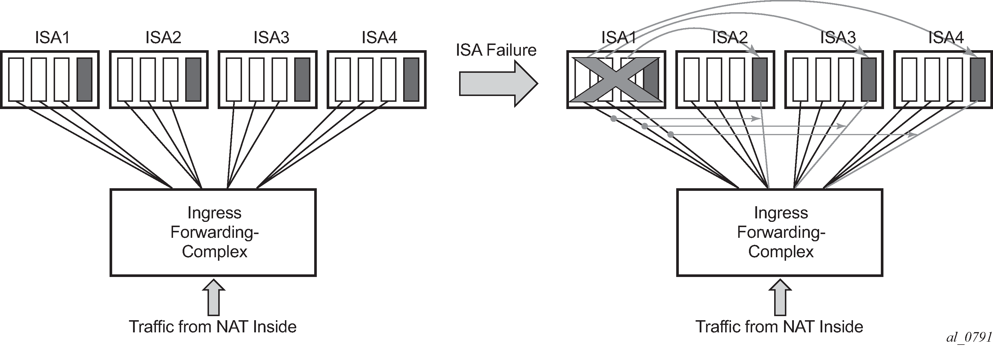
Active-active ISA redundancy model supports multiple failures simultaneously. The protection mechanism shown in Multiple failures is designed to protect against two simultaneous ISA failures. As the previous case, each ISA is divided into six members, three of which are carrying traffic under normal circumstances while the remaining three members have reserved memory resources.

Load distribution in active-active ISA redundancy model supporting single ISA failure shows resource utilization for a single ISA failure in relation to the total number of ISAs in the system. The resource utilization affects only scale of each ISA. However, bandwidth per ISA is not reserved and each ISA can operate at full speed at any time (with or without failures).
| Number of physical ISAs per system | Number of member ISAs per physical ISA (active/reserved) | Resource utilization per system in non-failed condition | Resource utilization per system with one failed ISA |
|---|---|---|---|
2 |
1A 1R |
50% |
100% |
3 |
2A 1R |
67% |
100% |
4 |
3A 1R |
75% |
100% |
5 |
3A 1R |
75% |
95% |
6 |
2A 1R |
66% |
83% |
7 |
2A 1R |
66% |
80% |
8 |
2A 1R |
66% |
79% |
9 |
1A 1R |
50% |
61% |
10 |
1A 1R |
50% |
60% |
11 |
1A 1R |
50% |
59% |
12 |
1A 1R |
50% |
58% |
13 |
1A 1R |
50% |
58% |
14 |
1A 1R |
50% |
57% |
Startup conditions
During the first five minutes of system startup or nat-group activation, the system behaves as if all ISAs are operational. Consequently, ISAs are segmented in its members according to the configured maximum number of supported failures.
Upon expiration of this initial five minute interval, the system is re-evaluated. In case that one of more ISAs are found in faulty state during re-evaluation, the members of the failed ISAs are distributed to the remaining ISAs that are operational.
Recovery
After a failed ISA is recovered, the system automatically accepts it and traffic is assigned to it. Traffic that is moved to the recovered ISA is interrupted.
Adding additional ISAs in the ISA group
Adding additional ISAs in an operational nat-group requires reconfiguration of the active mda-limit for the nat-group (or the failed mda-limit for that matter). This is only possible when nat-group is in an administratively shutdown state.
L2-Aware bypass
L2-Aware bypass provides the basis for traffic continuity if an MS-ISA fails. With L2-Aware bypass functionality disabled and without an intra-chassis redundancy scheme deployed (such as active/active or active/standby), the traffic to be processed by the failed MS-ISA is blackholed. This means that traffic continues to be sent to the failed MS-ISA. By enabling L2-Aware bypass, instead of being blackholed, the traffic is routed outside of the SR OS node without being NAT’d in accordance to the routing table in the inside routing context. The intent is that non-NAT’d traffic is intercepted by a central NAT node that performs the NAT function. This way, traffic served by the failed MS-ISA continues to be NAT’d by a central NAT node. The central NAT node provides redundancy for multiple SR OS nodes, therefore reducing the need to equip each individual SR OS node with multiple MS-ISAs which are normally used in an active/active or active/standby intra-chassis redundancy mode.
This concept is shown in L2-Aware bypass . The example shows the base router as an inside routing context where the global routing table (GRT) is used to decide where to send traffic if an MS-ISA is unavailable. Apart from this example, the inside routing context is not limited to the base router but instead can be an VPRN instance.
L2-Aware bypass is considered as an optional redundancy model in L2-Aware NAT which is mutually exclusive with the other two MS-ISA redundancy modes (active/active and active/standby).
L2-Aware bypass is enabled with the following CLI:
configure
 isa
   nat-group <id>
    redundancy {active-active|active-standby|l2aware-bypass}

Sharing IP addresses in L2-Aware NAT
L2-Aware NAT allows overlap of inside (private) IP addresses between Enhanced Subscriber Management (ESM) (or L2-Aware NAT) subscribers. For example, IP addresses assigned to hosts within, for example, subscriber SUB-1, can be identical to IP addresses assigned to hosts within, for example, subscriber SUB-2. This is possible by the subscriber-ID field (which must be unique in the system) that is a part of the NAT translation key. This way the return traffic (in downstream direction) belonging to different ESM subscribers with overlapping IP addresses can still be differentiated by a unique ESM subscriber-id field that is used in reverse NAT translation.
L2-Aware bypass functionality with a failed MS-ISA breaks the logic because traffic is not translated (NAT’d) in SR OS node, and therefore, the return traffic does not take subscriber-id field into forwarding consideration. For this reason, the overlap of inside (private) IP addresses between ESM subscribers is not supported by the L2-Aware bypass functionality for the routed traffic within the same inside routing context. In other words, private IP addresses must be unique across the subscribers within a specified inside routing context.
Recovery
Upon the recovery of the failed MS-ISA, all existing subscribers that are affected by the bypass continue to use the bypass. However, all new subscribers that come online after the recovery, are automatically L2-Aware NAT’d (and therefore do not use the bypass).
Restoring bypassed subscribers to the L2-Aware NAT after the recovery, requires manual intervention by the operator. This is accomplished by executing the tools perform nat recover-l2aw-bypass mda mda-id command:
In L2-Aware NAT, the <subscriber to outside IP, port-block> mappings are allocated during the subscriber attachment phase (when the subscriber comes online) and are maintained in the CPM. Therefore, they are preserved in the CPM during MS-ISA failure. This means that the original mappings for the recovered subscribers continue to be used when the MS-ISA is recovered.
Be aware that only the partial mappings <subscriber to outside IP, port-block> are preserved. This does not include preservation of NAT sessions sometimes referred as fully qualified flows. NAT sessions are maintained in MS-ISA and they are lost during MS-ISA failures. Hence, this model provides stateless failover to an external NAT node.
The operator is notified about the MS-ISA failure by a log message or an SNMP trap. An example of such log is:
9 2017/06/07 11:32:49.748 UTC MINOR: NAT #2020 Base NAT
"The NAT MDA 5/1 is now inactive in group 2."
Default bypass during reboot or MS-ISA provisioning
If enabled, L2-Aware bypass takes effect automatically if an MS-ISA does not become operational within 10 minutes of provisioning (configuring) or after a system bootup.
Logging
Because partial mappings in L2-Aware NAT <subscriber to outside IP addresses, port block> are preserved in the CPM during an MS-ISA failure, no logging is generated for existing ESM/NAT subscribers when the MS-ISA fails or is recovered.
Stateful inter-chassis NAT redundancy
Stateful inter-chassis NAT redundancy provides seamless NAT failover between the two redundant SR OS nodes. A pair of redundant nodes operates in active or standby modes per NAT group. If traffic distribution between the nodes is needed, then up to four NAT groups per node can be deployed, and with each NAT group having its own set of ISAs. In this scenario, traffic between the nodes can be load-balanced per NAT group.
CGN stateful inter-chassis redundancy shows a scenario where inside routes are advertised from the node with the active NAT group that ensures traffic is symmetric. This means that upstream and downstream traffic is fully flowing through the same node. Although this scenario represents the majority of use cases, it is allowed for the upstream traffic to arrive on the node with a standby NAT group and be shunted over to the node with active nat-group over a link that interconnects the two nodes. This scenario is shown in Asymmetric traffic.
The redundant pair of NAT nodes protect against the following:
node failure
ISA failure
link failure
path failure (BFD, VRRP)


The basic premise of stateful inter-chassis NAT redundancy is as follows:
ISAs/ESAs within a NAT group can be either active or standby. This means that in a pair of redundant NAT nodes, only one node attracts traffic per NAT group while the NAT group on the peering node is in a standby state with synchronized flows (or sessions).
The activity (active or standby) of a NAT group is determined by an internal health parameter that represents the node’s ability to perform NAT at full capacity. The value of the health parameter can change dynamically and is based on the events that are related to various failures against which the stateful inter-chassis NAT redundancy offers protection. The health value is communicated between the redundant (or peering) nodes on the CPM level.
In case of equal health, an operator can, through configuration, influence the activity of a NAT group.
The activity of a NAT group is characterized by the advertisement of the NAT- related routes on the inside (steering and destination-prefix) and the outside (pool routes).
Only TCP/UDP/ICMP flows that are older than the preconfigured amount of time are synchronized.
Flow synchronization is performed directly between the ISAs, bypassing the CPM. The CPM’s main role is to determine the activity of a NAT group with health related parameters as shown in NAT synchronization.
Flows are created on the active NAT group and are synchronized from the active NAT group to the standby NAT group.
Immediately following the switchover, all flows on the newly standby NAT group are resynchronized from the newly active NAT group.
If the link between the chassis is lost, then each chassis operates in a standalone mode.
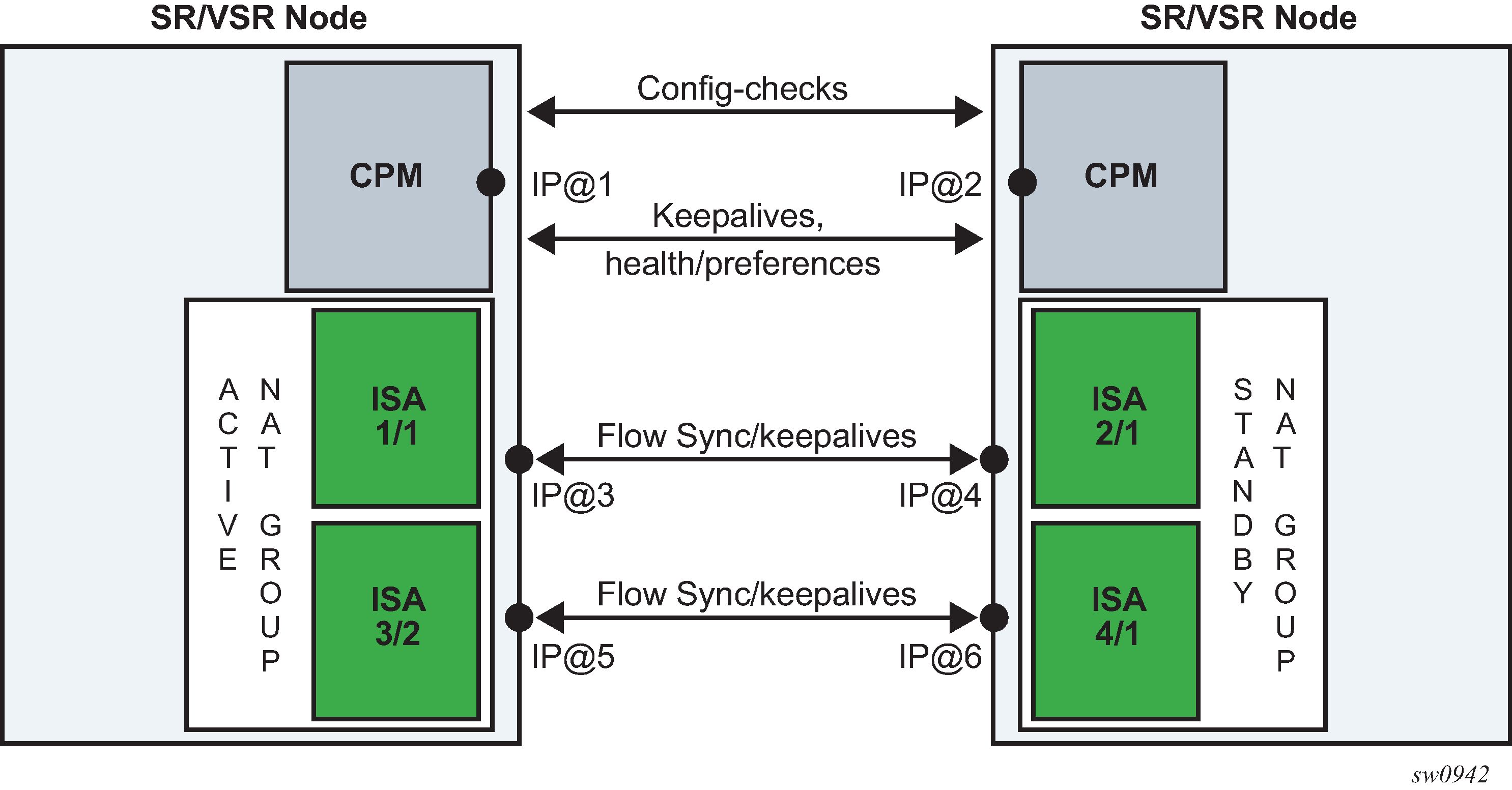
A reliable and redundant link should always be available between the two redundant NAT nodes. This link is referred to as Inter-Chassis Link (ICL) and is used for:
CPM communication (activity negotiation and presence detection)
ISA-to-ISA communication (flow synchronization)
transient forwarding of data traffic during switchovers
Health status and failure events
A health value determines the activity of a NAT group within a pair of redundant nodes. The health value of a NAT group is internally calculated. The system can automatically decrease this value depending on the events that can negatively affect the system’s ability to perform NAT at a needed capacity.
A NAT group with a higher health value becomes active.
Activity states at equal health shows activity states, if paired NAT groups have equal health values on both nodes. Preferred is a configuration parameter that influences the activity state for a pair of NAT groups with equal health value (typical use case would be load balancing per NAT group).
| Node 1 | Node 2 | Active node | Comments |
|---|---|---|---|
no preferred configured |
no preferred configured |
Whichever node becomes active first, remains active |
If both nodes are becoming active simultaneously, the node with the highest system chassis MAC address becomes a controller node that decides which node becomes active node and which standby based on the health and preference values. When the health and preference are equal, the controller node does not preempt (trigger a switchover) an already active node. |
preferred configured |
no preferred configured |
Node 1 |
Node 1 always preempts Node 2 (if the health values are equal) |
no preferred configured |
preferred configured |
Node 2 |
Node 2 always preempts Node 1 (if the health values are equal) |
preferred configured |
preferred configured |
Whichever node becomes active first, remains active |
Same as for no preference on both nodes |
The health parameter is initially set to a value of 1000 under the following circumstances:
The number of active ISAs in a NAT group is matching the configured value for the active-mda-limit configuration parameter.
There are no port failures that are being monitored.
There are no failures within the operation groups that are being monitored.
The above circumstances imply that the system is fully operational with no failures that would affect NAT operation.
However, the health value can be influenced by the events that can affect NAT operation, and that are outside of ISA-related failures, for example, unhealthy ports and paths that lead traffic in and out of the NAT node. Such events are explicitly tracked or monitored for the purpose of dynamically adjusting the health value and therefore influencing the activity of the NAT groups.
Stateful inter-chassis NAT redundancy protects against the following failures:
Nodal failure; if the active node fails, the standby node is notified of such an event by the lack of received keepalives.
ISA failure; a NAT group must have exactly the active-mda-limit number of ISAs that are operationally up to participate in stateful inter-chassis NAT redundancy. If the number of operational ISAs falls below the configured limit, then the health of the NAT group drops to 0.
Ports on the node can be monitored, and their operational state can trigger a change of the health value.
BFD sessions on the node can be monitored using the oper-groups and their state change can trigger a change of the health value.
VRRP instances under interface configurations can be monitored using the oper-groups and their state change can trigger a change of the health value.
SAPs on the node can be monitored using the oper-groups and their operational state can trigger a change of the health value.
Port and oper-group state change influences the reachability of the NAT node and consequently this affects network-wide NAT operation. If that port or path capacity in and out of the NAT node drops below a specific level, a switchover to a healthier NAT node may be needed.
Port states can be tracked or monitored on the private side (inside) and on the public side (outside) of NAT.
Oper-groups are constructs that are tracking states of BFD enabled interfaces, SAPs, and VRRP instances.
BFD sessions targeted to the next hop can traverse intermediate Layer 2 nodes and can have longer reach than port tracking.
Another benefit of monitoring ports and paths is that it can help reduce the amount of traffic on the inter-chassis communication link (ICL) if that active node loses direct connection to the node downstream or upstream from it. The link for inter-chassis control communication (ICL) must always be present (for synchronization purposes). However, this link does not need to be designed for heavy traffic loads during extended periods of time occurs if traffic bearing ports are not colocated with the active node. However, this link is used for shorter transient periods that are caused by switchovers.
Route advertisements
NAT-related routes are active only on the node with the active NAT group. On the outside, these are the pool routes that attract traffic in the downstream direction. On the inside, the destination-prefix (which can be configured per NAT policy) represents a route that diverts traffic to NAT in the upstream direction. In case of a filter-based diversion to NAT, a steering route is advertised only from the active node. The following are the steering-route contexts.
config>router>nat>inside>redundancy>steering-route ip-prefix/length
config>service>vprn>nat>inside>redundancy>steering-route ip-prefix/length
The route advertisement concept is shown in Route advertisement.

Flow synchronization
The goal of flow synchronization is to minimize service interruption after a switchover. Minimum service interruption in this context allows some packet drop during a switchover, but the user sessions are preserved without requiring a user to restart them. Flows are synchronized directly between the ISAs at the time of creation and deletion, and always only from the active side to the standby side.
The amount of traffic carried across the inter-chassis link is proportional to the number of flows that are synchronized, and it also depends on the NAT type (NAT44, DS-Lite or NAT64). The size of a flow record on the wire is around 100 bytes and a number of flow records can be packed into a single frame whose MTU is adjustable. With approximately 90 bytes of header overhead per frame, and the number of synchronized flows, it is relatively easy to estimate the required bandwidth of the inter-chassis links. The minimum recommended bandwidth of the inter-chassis link is 10 Gb/s.
Excluding short-lived flows from synchronization could further reduce the necessary bandwidth for synchronization. The flow replication threshold is configurable:
 configure
      isa
         nat-group <id>
            active-mda-limit <limit>
            inter-chassis-redundancy
               replication-threshold <seconds>   [0..300]
For the replication-threshold, Nokia recommends choosing a value that is larger than any of the typical short-lived flows that are not closed by the protocol itself but rely on the timeout value for its expiration (udp-dns, udp-initial, or icmp-query).
After a switchover, a resynchronization of flows occurs. The new standby ISA starts clearing all its flows and the synchronization process restarts. This means that an attempt is made to resynchronize flows from the currently active side to the standby side. During this process, the active ISAs continue to forward traffic and create new flows.
While the flow synchronization is in progress, a switchover is not allowed unless the health on the active side drops to 0, which means that one or more ISAs on the active side have failed.
Loss of synchronization
After the loss of synchronization, an ISA transitions into a ‟com-sync” state. Some of the events that can cause loss of synchronization on the ISA level are:
Misconfigurations such as:
pools not matching on both nodes (outside IPs do not match between the ISAs)
NAT policies not matching on both nodes
ISA-to-ISA timeout. If an ACK for any flow synchronization frame is not received within one second, the system transitions to a non-synchronized state.
When the synchronization is lost, the standby ISA starts clearing all the flows and the synchronization process restarts. This means that an attempt is made to resynchronize flows from the currently active side to the standby side. During this process, the active ISAs continue to forward traffic and create new flows.
Flow timeout on the standby node
When a flow is synchronized to a standby ISA, its record is present in the standby ISA until it is deleted explicitly by the active node with a delete synchronization message. There are no additional updates sent for that flow from the active node between its creation and deletion time.
Flow timeout following the switchover
When an ISA transitions from a standby to an active state, the timeout for the synchronized flows on the newly active ISA is set to a percentage of the flow timeout value that is configured in the NAT policy. Timeout of the flow refers to the clearing of its state in NAT after a period of traffic inactivity. Flow timeouts are configured in the NAT policy. This adjustment of the flow timeout on the newly active ISA is necessary because the standby ISA, although aware of the flows, is not aware of the flow forwarding status at the time of the switchover. In other words, the flow on the active node just before the switchover may have been inactive and close to the timer expiry. In this case, it may not be desirable to extend the life time of such a flow on the newly active ISA to its initially configured value.
This flow timeout after the switchover is set by the following command:
config>isa>nat-group>inter-chassis-redundancy>flow-timeout-on-switchover percent [1..50]
A value of 50 for the flow-timeout-on-switchover means that synchronized flows on the newly active ISA inherits half of the value set in the NAT policy.
Rapid consecutive switchovers
Excessive switchovers can be caused by unstable network elements. Events causing instability should be dampened at the source (ports may support event dampening). Event dampening control is not configurable under NAT. However, a dampening mechanism is built into stateful inter-chassis NAT redundancy by not allowing a switchover while synchronization is in progress.
Considering that a full re-synchronization is triggered after every switchover, the next switchover can occur only after the amount of time needed for full synchronization of flows. The new standby starts deleting flows and after this is completed, all flows from the newly active ISA are copied over to the standby.
ISA-to-ISA communication
Flow synchronization occurs directly between the ISAs, bypassing CPMs. Each ISA has its own IP address through which it communicates with its counterpart on the peering node.
Although each ISA has its own IP address, only one IP address in a NAT group is configured. This IP address is used by one of the ISAs and the rest of the ISAs are assigned consecutive IP addresses automatically by the system.
Preemption
Preemption is a feature that allows one node to relinquish activity to a peering node when the health values are equal. This functionality can be enabled through configuration (preferred CLI command). If one of the nodes in the redundant pair is enabled for preemption (has a preferred keyword configured), then this node, upon a boot up, takes over the activity from the existing active peering node with the same health value.
In a setup with two nodes with the same health value and no preferred command is configured on either node, the currently active node remains active and does not relinquish its activity status to a just booted up node unless the health value is changed.
If the health values are different between the peering nodes, preemption is automatically disabled, and the activity is driven solely by the health value.
A freshly booted node that is about to take over the activity from an existing node (because of preemption), waits for all the flows to be synchronized and transferred from the currently active node. Only after this transfer is complete, does switchover occur.
Message delivery prioritization
Control messages originated by the CPM that pertain to NAT redundancy are treated with the highest priority and are marked by the system with a DSCP value of Network Control NC1 (48d). Those messages are crucial to stability of NAT redundancy (otherwise inadvertent switchovers could occur).
Flow synchronization control messages originated by ISAs are marked with EF (46d) for DSCP and 5 for dot1p, which are lower priorities than CPM-originated messages. The sync (ISA keepalive) messages are sent with DSCP NC1 and dot1p 6.
Flow synchronization messages are more tolerant to delays and loss.
Both of these types of control messages should be higher priority than any customer -originated traffic that is expected to cross the ICL. Customer traffic can be marked in SR OS node by the appropriate QoS configuration on egress interfaces.
Subscriber-aware NAT
Subscriber-aware information must be supplied to both nodes (active and standby) through RADIUS accounting.
With Nokia BNG, the following configuration ensures that subscriber information is sent through RADIUS to more than one target:
*A:BNG1>config>subscr-mgmt>sub-prof# info
----------------------------------------------
            radius-accounting
                policy "acct-nat-1" "acct-nat-2"
            exit
Accounting policies contain respective NAT node destinations and consequently the subscriber information is sent to both NAT nodes.
Matching configuration on redundant pair of nodes
A pair of nodes participating in stateful NAT inter-chassis redundancy must have matching NAT configurations, the inside service-id and outside service-id. That is, parameters other than the configuration items referring to local objects, such as ports and interfaces, should be configured with the same values on both nodes.
For example,
config isa nat-group inter-chassis-redundancy keepalive interval dropcount count
must be the same on both nodes.
However, the statement
config isa nat-group inter-chassis-redundancy monitor-port port-id
does not need to match because each node can monitor its own set of unique ports, or not monitor ports at all.
Detection of configuration mismatch is logged in the system and operators are encouraged to check the logs periodically for any misaligned statements.
Online configuration changes
Certain NAT configuration changes can be performed online, which allows NAT to continue running in a redundant configuration.
In classic CLI, the user cannot perform the following online:
-
delete flows
-
block subscribers
In MD-CLI, these changes are allowed; however, during the commit, the inter-chassis NAT redundancy is temporarily disabled and then re-enabled after the commit is completed. Examples of configuration changes that require halting synchronization, include manipulation of NAT pools with active flows or subscribers, or removing NAT policies for active subscribers.
For configuration changes that can be performed online without halting the synchronization, there is a period during which the configuration between the nodes are misaligned (while the user is performing configuration changes). During these periods, the system continuously tries to synchronize the configuration. This perpetual attempt to synchronize flows is demanding for processing power and Nokia recommends it should be avoided.
To properly perform NAT configuration changes in a redundant configuration, the user must temporarily disable synchronization of the flows between the nodes with the following configuration. Perform the changes to the NAT configuration in an inter-chassis redundant setup.
MD-CLI
A:admin@node-2#
   isa
      nat-group 1 {
          redundancy {
              inter-chassis {
                  sync false
              }
          }
      }
classic CLI
----------------------------------------------
        nat-group 1 create
            no shutdown
            redundancy inter-chassis
            active-mda-limit 1
            exit
        exit
----------------------------------------------
In this configuration, the nodes continue to operate in active or standby mode but the newly added and deleted flows on the active node are not synchronized. During this non-synchronizing period, the user can make any NAT changes that are possible in a standalone node. When the configuration changes are performed, the sync command must be reversed on both nodes. At that point, the two nodes resynchronize.
Setting up inter-chassis redundancy
-
Disable the committed synchronization of flows between the ISAs or ESAs on both
nodes.
MD-CLI
A:node-2>config>isa>nat-group>redundancy inter-chassis sync false
A:node-2>config>isa>nat-group commit
classic CLIA:node-2>config>isa>nat-group>inter-chassis-redundancy# no sync
This sync command causes the nodes to behave as if the flow synchornizations are not configured, which allows the online configuration changes.
The order in which the nodes (active or standby) are configured is irrelevant.
- Perform the configuration changes on both nodes.
-
Re-enable synchronization of flows on both nodes.
MD-CLI
A:node-2>config>isa>nat-group>redundancy inter-chassis sync true
A:node-2>config>isa>nat-group commit
classic CLIA:node-2>config>isa>nat-group>inter-chassis-redundancy# sync
Scenario with monitoring ports
This example relies on the following assumptions in Port monitoring scenario:
Load sharing over redundant chassis is achieved through two nat-groups that are, under normal conditions (no failures), active on respective chassis:
nat-group 1 is active on NAT node 1.
nat-group 2 is active on NAT node 2.
Two 100G links on the network/public/outside side are shared between the two NAT groups on each node (Internet access). These links are redundant, and failure of one link does not have a negative effect on the traffic.
Each NAT group has five 10G ports connected on the subscriber/private/inside side. Planned traffic load over those links is between 30G and 40G, which means that one link can be safely lost, without affecting traffic in the NAT group.
The operator’s rules for managing failures are the following:
The scheme protects against two access link failures per NAT group and one network link failure, simultaneously.
The scheme protects against three access link failures per NAT group, simultaneously. However, in this case, there cannot be any network link failures.
In the two above scenarios, if both network links fail on the same node (while on the other node at least one is available), the node with two failed links becomes standby.
According to those rules, the following configuration can be applied:
configure
   isa
      nat-group 1
         active-mda-limit 5
         inter-chassis-redundancy
            monitor-port port-1 health-drop 6
            monitor-port port-2 health-drop 6
            monitor-port port-3 health-drop 6
            monitor-port port-4 health-drop 6
            monitor-port port-5 health-drop 6
            monitor-port port-11 health-drop 10
            monitor-port port-12 health-drop 10

The results for a randomly selected number of failure combinations (out of 360 valid combinations) is shown in Randomly selected number of failure combinations .
‟N” indicates that the priority is equal, and unless preemption is enabled, the node that becomes active first, remains active.
| Node | Number of failures in nat-group 1 (10G ports) |
Number of failures in nat-group 2 (10G ports) |
Number of failures on shared network side (100G ports) |
Health of nat-group 1 | Health of nat-group 2 | State of nat-group 1 (active/standby) | State of nat-group 2 (active/standby) |
|---|---|---|---|---|---|---|---|
1 2 |
0 1 |
0 0 |
0 1 |
1000 984 |
1000 990 |
A S |
A S |
1 2 |
0 2 |
0 1 |
1 1 |
990 978 |
990 984 |
A S |
A S |
1 2 |
0 0 |
1 0 |
0 0 |
1000 1000 |
994 1000 |
N N |
S A |
1 2 |
1 2 |
1 0 |
0 0 |
1000 988 |
994 1000 |
A S |
S A |
1 2 |
1 0 |
0 2 |
1 1 |
984 990 |
990 978 |
S A |
A S |
1 2 |
1 2 |
1 1 |
1 1 |
984 978 |
984 984 |
A S |
N N |
1 2 |
1 1 |
2 0 |
0 0 |
994 994 |
988 1000 |
N N |
S A |
1 2 |
1 0 |
2 1 |
1 1 |
984 990 |
978 984 |
S A |
S A |
1 2 |
1 2 |
2 0 |
1 1 |
984 978 |
978 990 |
A S |
S A |
1 2 |
2 0 |
2 2 |
0 1 |
988 990 |
988 978 |
S A |
A S |
Configuring stateful inter-chassis NAT redundancy
Stateful inter-chassis NAT redundancy requires synchronization on the CPM level and on the ISA and ESA levels.
CPM level synchronization is required to primarily exchange health information and keepalives between the nodes for the purpose of determining active and standby NAT groups between the two peers (nodes). Each peer is identified by a single IP address. The level of traffic exchanged between the peers for CPM synchronization is low.
The ISA or ESA level synchronization is required to synchronize flows between the ISA or ESAs. Each ISA or ESA becomes a peer and is identified by its own IP address. The level of traffic exchanged between ISA or ESA for synchronization purposes depends on the configuration and the amount of NAT traffic.
Basic configuration steps are described below with command syntax examples. Some of the steps are optional and can assume default values. For more information about each command, see the 7450 ESS, 7750 SR, 7950 XRS, and VSR Classic CLI Command Reference Guide.
Configure a synchronization peer on the CPM level. The health of the NAT group is exchanged between the chassis and the node that is elected as active for the NAT group. The other node becomes the standby for the same NAT group.
configure redundancy multi-chassis peer 192.0.2.0 nat nat-group 1 sync-tag ‟some-tag”Configure keepalives between the nodes (CPMs).
configure isa nat-group 1 inter-chassis-redundancy nat keepalive 50 dropcount 2Configure the minimum duration of the flow before it is synchronized. The operator may choose to synchronize only long-lived flows.
configure isa nat-group 1 inter-chassis-redundancy nat replication-threshold 60Configure a timeout of the flow after a switchover. Independent of stateful redundancy, and depending on the type of traffic, each flow has a timeout value that determines its expiration time if there is inactivity. The initial flow timeouts are configured in a NAT policy. After a switchover, this timeout can be reset to the percentage of the originally-configured value. This can be useful because some of the flows switched over may already have been in an inactive state before the switchover.
configure isa nat-group 1 inter-chassis-redundancy nat flow-timeout-on-switchover 10Configure the IP-MTU size of the packets carrying flow synchronization information between the ISA or ESAs.
configure isa nat-group 1 inter-chassis-redundancy nat ip-mtu 9000Configure the IP address of the first ISA or ESA in a NAT group on local and remote nodes. The IP addresses for the remaining ISA or ESA are assigned automatically consecutively. These are peering addresses between the ISA and ESAs over which the flows are synchronized. Traffic from the first IP address on the local node is sent to the first IP address on the remote node.
configure isa nat-group 1 inter-chassis-redundancy nat local-ip-range-start 203.0.113.1
configure isa nat-group 1 inter-chassis-redundancy nat remote-ip-range-start 203.0.113.100
Configure parameters related to the monitoring status of the ports and other objects, such as SAPs, BFD sessions, or VRRP sessions in the system. The status of those object can affect the health of the system and can trigger a switchover.
configure isa nat-group 1 inter-chassis-redundancy nat monitor-oper-group ‛demo-grp’ health-drop 100
configure isa nat-group 1 inter-chassis-redundancy nat monitor-port 1/1/1 health-drop 50
Select the activity preference for a NAT group.
configure isa nat-group 1 inter-chassis-redundancy nat preferredReference a routing instance through which ISA or ESAs on redundant nodes exchange synchronization information.
configure isa nat-group 1 inter-chassis-redundancy nat router ‟Base”
Related show commands include the following:
show isa nat-group 3
show isa nat-group 3 inter-chassis-redundancy
show isa nat-group 3 inter-chassis-redundancy statistics
show isa nat-group 3 member 1 inter-chassis-redundancy
show isa nat-group 3 member 1 inter-chassis-redundancy statistics
ISA feature interactions
This section describes the interaction between MS-ISA applications and other system features.
MS-ISA use with service mirrors
All MS-ISA uses include support for service mirroring running with no feature interactions or impacts. For example, any service diverted to AA, IPsec, NAT, LNS, or supported combinations of MS-ISA application also supports service mirroring simultaneously.
Network Address Translation
Subscriber aware Large Scale NAT44
Subscriber aware Large Scale NAT44 attempts to combine the positive attributes of Large Scale NAT44 and L2-Aware NAT, namely:
the ability for some traffic to bypass the NAT function, such as IPTV traffic and VoIP traffic whenever a unique IP address per subscriber is used (for example, not L2-Aware NAT where all subs share the same IP). This can be achieved using existing Large Scale NAT44 mechanisms (ingress IP-filters)
the use of RADIUS Acct for logging of port-ranges, including multiple port-range blocks
the use of subscriber-identification/RADIUS username to identify the customer to simplify management of Large Scale NAT44 subscribers
Subscriber awareness in Large Scale NAT44 facilitates the release of NAT resources immediately after the BNG subscriber is terminated, without having to wait for the last flow of the subscriber to expire on its own (TCP timeout is 4hours by default).
The subscriber aware Large Scale NAT44 function leverages RADIUS accounting proxy built-in to the 7750 SR. The RADIUS accounting proxy allows the 7750 SR to inform Large Scale NAT44 application about individual BNG subscribers from the RADIUS accounting messages generated by a remote BNG and use this information in the management of Large Scale NAT44 subscribers. The combination of the two allows, for example, the 7750 SR running as a Large Scale NAT44 to make the correlation between the BNG subscriber (represented in the Large Scale NAT44 by the Inside IP Address) and RADIUS attributes such as User-Name, Alc-Sub-Ident-String, Calling-Station-Id or Class. These attributes can subsequently be used for either management of the Large Scale NAT44 subscriber, or in the NAT RADIUS Accounting messages generated by the 7750 SR Large Scale NAT44 application. Doing so simplifies both the administration of the Large Scale NAT44 and the logging function for port-range blocks.
As BNG subscribers authenticate and come online, the RADIUS accounting messages are ‛snooped’ through RADIUS accounting proxy which creates a cache of attributes from the BNG subscriber. BNG subscribers are correlated with the NAT subscriber by framed-ip address, and one of the following attributes that must be present in the accounting messages generated by BNG:
username
subscriber ID
RADIUS Class attribute
Calling-Station-id
IMSI
IMEI
Framed-ip address must also be present in the accounting messages generated by BNG.
Large Scale NAT44 Subscriber Aware application receives a number of cached attributes which are used for appropriate management of Large Scale NAT44 subscribers, for example:
Delete the Large Scale NAT44 subscriber when the BNG subscriber is terminated.
Report attributes in Large Scale NAT44 accounting messages according to configuration options.
Creation and removal of RADIUS accounting proxy cache entries related to BNG subscriber is triggered by the receipt of accounting start/stop messages sourced by the BNG subscriber. Modification of entries can be triggered by interim-update messages carrying updated attributes. Cached entries can also be purged via CLI.
In addition to passing one of the above attributes in Large Scale NAT44 RADIUS accounting messages, a set of opaque BNG subscriber RADIUS attributes can optionally be passed in Large Scale NAT44 RADIUS accounting messages. Up to 128B of these opaque attributes are accepted. The remaining attributes are truncated.
Large Scale NAT44 subscriber instantiation can optionally be denied in case that corresponding BNG subscriber cannot be identified in Large Scale NAT44 through RADIUS accounting proxy.
Configuration guidelines:
Configure RADIUS accounting proxy functionality in a routing instance that receives accounting messages from the remote or local BNG. Optionally forward received accounting message received by RADIUS accounting proxy to the final accounting destination (accounting server).
Point the BNG RADIUS accounting destination to the RADIUS accounting proxy – this way RADIUS accounting proxy receives and ‛snoop’ BNG RADIUS accounting data.
BNG subscriber can be associated with two accounting policies, therefore pointing to two different accounting destinations. For example, one to the RADIUS accounting proxy, the other one to the real accounting server.
Configure subscriber aware Large Scale NAT44. From Large Scale NAT44 Subscriber Aware application reference the RADIUS Proxy accounting server and define the string that is used to correlate BNG subscriber with the Large Scale NAT44 subscriber.
Optionally enable NAT RADIUS accounting that includes BNG subscriber relevant data.
(1)
*A:left-a20>config>service>vprn#
      radius-proxy
                server "proxy-acct" purpose accounting create
                    default-accounting-server-policy "lsn-policy"
                   description "two side server -interface:client ; default-plcy:real server"
                    interface "rad-proxy-loopback"
                    secret "TEg1UEZzemRMyZXD1HvvQGkeGfoQ58MF" hash2
                    no shutdown
                exit
            exit
RADIUS accounting proxy listens to accounting messages on interface ‛rad-proxy-loopback’.
The name ‛proxy-acct’ as defined by the server command is used to reference this proxy accounting server from Large Scale NAT44.
Received accounting messages can be relayed further from RADIUS accounting proxy to the accounting server which can be indirectly referenced in the default-accounting-policy ‛lsn-policy’.
The lsn-policy is defined as:
*A:left-a20>config>aaa#
               radius-server-policy "lsn-policy" create
            servers
                router "Base"
                source-address 192.168.1.12
                server 1 name "192"
            exit
        exit
This lsn-policy can then reference an external RADIUS accounting server with its own security credentials. This external accounting server can be configured in any routing instance.
*A:left-a20>config>router>radius-server# info
----------------------------------------------
            server "192" address 192.168.1.10 secret "KRr7H.K3i0z9O/hj2BUSmdJUdl.zWrkE" hash2 port 1813 create
                description "real radius or acct server"
            exit
(2)
Two RADIUS accounting policies can be configured in BNG, one to the real RADIUS server, the other one to the RADIUS accounting proxy.
*A:left-a20>config>subscr-mgmt>sub-prof# info
----------------------------------------------
            radius-accounting-policy "real-acct-srvr"  duplicate ‟lsn”
            egress
                agg-rate-limit 10000
            exit
----------------------------------------------
*A:left-a20>config>subscr-mgmt>acct-plcy# info
----------------------------------------------
            description ‟lsn  radius-acct-policy”
update-interval 5
            include-radius-attribute
                acct-authentic
                acct-delay-time
                called-station-id
                calling-station-id remote-id
                circuit-id
                framed-interface-id
                framed-ip-addr
                framed-ip-netmask
                mac-address
                nas-identifier
                nas-port-id
                nas-port-type
                nat-port-range
                remote-id
                sla-profile
                sub-profile
                subscriber-id
                user-name
                alc-acct-triggered-reason
            exit
            session-id-format number
            radius-accounting-server
                router 10  (service id where proxy radius is configured)
                server 1 address 10.5.5.5 secret "cVi1sidvgH28Pd9QoN1flE" hash2
   (radius proxy IP address is 10.5.5.5 on interface ‟rad-proxy-loopback”; the ‛secret’ is the same as configured on RADIUS accounting proxy)
            exit
(3)
Sub-aware Large Scale NAT44 references the RADIUS accounting proxy server ‛proxy-acct’ and defines the calling-station-id attribute from the BNG subscriber as the matching attribute:
*A:left-a20>config>service>vprn>nat>inside# info
----------------------------------------------
   nat-policy "nat-base"
      destination-prefix 10.0.0.0/16
      subscriber-identification
          attribute vendor "standard" attribute-type "station-id"
      description "sub-aware CGN"
      radius-proxy-server router 10 name "proxy-acct"
      no shutdown
    exit

----------------------------------------------
(4)
Optionally RADIUS NAT accounting can be enabled:
*A:left-a20>config>isa>nat-group# info
----------------------------------------------
            active-mda-limit 1
            radius-accounting-policy "nat-acct-basic"
            mda 1/2
            no shutdown

*A:left-a20>config>aaa>isa-radius-plcy# info detail
----------------------------------------------
            description "radius accounting policy for NAT"
            include-radius-attribute
                framed-ip-addr
                nas-identifier
                nat-subscriber-string
                user-name
                inside-service-id
                outside-service-id
                outside-ip
                port-range-block
                hardware-timestamp
                release-reason
                multi-session-id
                frame-counters
                octet-counters
                session-time
                called-station-id
                subscriber-data
            exit
            radius-accounting-server
                access-algorithm direct
                retry 3
                router "Base"
                source-address-range 192.168.1.20 192.168.1.20
                timeout sec 5
                server 1 address 192.168.1.10 secret "KlWIBi08CxTyM/YXaU2gQitOu8GgfSD7Oj5hjese27A" hash2 port 1813
            exit
----------------------------------
Such setup would produce a stream of following Large Scale NAT44 RADIUS accounting messages:
Mon Jul 16 10:59:27 2012
        NAS-IP-Address = 10.1.1.1
        NAS-Identifier = "left-a20"
        NAS-Port = 37814272
        Acct-Status-Type = Start
        Acct-Multi-Session-Id = "500456500365a4de7c29a9a07c29a9a0"
        Acct-Session-Id = "500456500365a4de6201d7b87c29a9a0"
        Called-Station-Id = "00-00-00-00-01-01"
        User-Name = "remote0"
        Calling-Station-Id = "remote0"
        Alc-Serv-Id = 10
        Framed-IP-Address = 10.0.0.7
        Alc-Nat-Outside-Ip-Addr = 198.51.100.1
        Alc-Nat-Port-Range = "198.51.100.1 1054-1058 router base"
        Acct-Input-Packets = 0
        Acct-Output-Packets = 0
        Acct-Input-Octets = 0
        Acct-Output-Octets = 0
        Acct-Input-Gigawords = 0
        Acct-Output-Gigawords = 0
        Acct-Session-Time = 0
        Event-Timestamp = "Jul 16 2012 10:58:40 PDT"
        NAS-IP-Address = 10.1.1.1
        User-Name = "cgn_1_ipoe"
        Framed-IP-Netmask = 255.255.255.0
        Class = 0x63676e2d636c6173732d7375622d6177617265
        NAS-Identifier = "left-a20"
        Acct-Session-Id = "D896FF0000000550045640"
        Event-Timestamp = "Jul 16 2012 10:58:24 PDT"
        NAS-Port-Type = Ethernet
        NAS-Port-Id = "1/1/5:5.10"
        Acct-Delay-Time = 0
        Acct-Authentic = RADIUS
        Acct-Unique-Session-Id = "10f8bce6e5e7eb41"
        Timestamp = 1342461567
        Request-Authenticator = Verified

Mon Jul 16 11:03:56 2012
        NAS-IP-Address = 10.1.1.1
        NAS-Identifier = "left-a20"
        NAS-Port = 37814272
        Acct-Status-Type = Interim-Update
        Acct-Multi-Session-Id = "500456500365a4de7c29a9a07c29a9a0"
        Acct-Session-Id = "500456500365a4de6201d7b87c29a9a0"
        Called-Station-Id = "00-00-00-00-01-01"
        User-Name = "remote0"
        Calling-Station-Id = "remote0"
        Alc-Serv-Id = 10
        Framed-IP-Address = 10.0.0.7
        Alc-Nat-Outside-Ip-Addr = 198.51.100.1
        Alc-Nat-Port-Range = "198.51.100.1 1054-1058 router base"
        Acct-Input-Packets = 0
        Acct-Output-Packets = 1168
        Acct-Input-Octets = 0
        Acct-Output-Octets = 86432
        Acct-Input-Gigawords = 0
        Acct-Output-Gigawords = 0
        Acct-Session-Time = 264
        Event-Timestamp = "Jul 16 2012 11:03:04 PDT"
        Acct-Delay-Time = 5
        NAS-IP-Address = 10.1.1.1
        User-Name = "cgn_1_ipoe"
        Framed-IP-Netmask = 255.255.255.0
        Class = 0x63676e2d636c6173732d7375622d6177617265
        NAS-Identifier = "left-a20"
        Acct-Session-Id = "D896FF0000000550045640"
        Acct-Session-Time = 279
        Event-Timestamp = "Jul 16 2012 11:03:04 PDT"
        NAS-Port-Type = Ethernet
        NAS-Port-Id = "1/1/5:5.10"
        Acct-Delay-Time = 0
        Acct-Authentic = RADIUS
        Acct-Unique-Session-Id = "10f8bce6e5e7eb41"
        Timestamp = 1342461836
        Request-Authenticator = Verified

Mon Jul 16 11:04:34 2012
        NAS-IP-Address = 10.1.1.1
        NAS-Identifier = "left-a20"
        NAS-Port = 37814272
        Acct-Status-Type = Stop
        Acct-Multi-Session-Id = "500456500365a4de7c29a9a07c29a9a0"
        Acct-Session-Id = "500456500365a4de6201d7b87c29a9a0"
        Called-Station-Id = "00-00-00-00-01-01"
        User-Name = "remote0"
        Calling-Station-Id = "remote0"
        Alc-Serv-Id = 10
        Framed-IP-Address = 10.0.0.7
        Alc-Nat-Outside-Ip-Addr = 198.51.100.1
        Alc-Nat-Port-Range = "198.51.100.1 1054-1058 router base"
        Acct-Terminate-Cause = Host-Request
        Acct-Input-Packets = 0
        Acct-Output-Packets = 1321
        Acct-Input-Octets = 0
        Acct-Output-Octets = 97754
        Acct-Input-Gigawords = 0
        Acct-Output-Gigawords = 0
        Acct-Session-Time = 307
        Event-Timestamp = "Jul 16 2012 11:03:47 PDT"
        NAS-IP-Address = 10.1.1.1
        User-Name = "cgn_1_ipoe"
        Framed-IP-Netmask = 255.255.255.0
        Class = 0x63676e2d636c6173732d7375622d6177617265
        NAS-Identifier = "left-a20"
        Acct-Session-Id = "D896FF0000000550045640"
        Acct-Session-Time = 279
        Event-Timestamp = "Jul 16 2012 11:03:04 PDT"
        NAS-Port-Type = Ethernet
        NAS-Port-Id = "1/1/5:5.10"
        Acct-Delay-Time = 0
        Acct-Authentic = RADIUS
        Acct-Unique-Session-Id = "10f8bce6e5e7eb41"
        Timestamp = 1342461874
        Request-Authenticator = Verified
The matching accounting stream generated on the BNG is shown below:
Mon Jul 16 10:59:11 2012
        Acct-Status-Type = Start
        NAS-IP-Address = 10.1.1.1
        User-Name = "cgn_1_ipoe"
        Framed-IP-Address = 10.0.0.7
        Framed-IP-Netmask = 255.255.255.0
        Class = 0x63676e2d636c6173732d7375622d6177617265
        Calling-Station-Id = "remote0"
        NAS-Identifier = "left-a20"
        Acct-Session-Id = "D896FF0000000550045640"
        Event-Timestamp = "Jul 16 2012 10:58:24 PDT"
        NAS-Port-Type = Ethernet
        NAS-Port-Id = "1/1/5:5.10"
        ADSL-Agent-Circuit-Id = "cgn_1_ipoe"
        ADSL-Agent-Remote-Id = "remote0"
        Alc-Subsc-ID-Str = "CGN1"
        Alc-Subsc-Prof-Str = "nat"
        Alc-SLA-Prof-Str = "tp_sla_prem"
        Alc-Client-Hardware-Addr = "2001:db8:65:05:10:01"
        Acct-Delay-Time = 0
        Acct-Authentic = RADIUS
        Acct-Unique-Session-Id = "9c1723d05e87c043"
        Timestamp = 1342461551
        Request-Authenticator = Verified

Mon Jul 16 11:03:51 2012
        Acct-Status-Type = Interim-Update
        NAS-IP-Address = 10.1.1.1
        User-Name = "cgn_1_ipoe"
        Framed-IP-Address = 10.0.0.7
        Framed-IP-Netmask = 255.255.255.0
        Class = 0x63676e2d636c6173732d7375622d6177617265
        Calling-Station-Id = "remote0"
        NAS-Identifier = "left-a20"
        Acct-Session-Id = "D896FF0000000550045640"
        Acct-Session-Time = 279
        Event-Timestamp = "Jul 16 2012 11:03:04 PDT"
        NAS-Port-Type = Ethernet
        NAS-Port-Id = "1/1/5:5.10"
        ADSL-Agent-Circuit-Id = "cgn_1_ipoe"
        ADSL-Agent-Remote-Id = "remote0"
        Alc-Subsc-ID-Str = "CGN1"
        Alc-Subsc-Prof-Str = "nat"
        Alc-SLA-Prof-Str = "tp_sla_prem"
        Alc-Client-Hardware-Addr = "2001:db8:65:05:10:01"
        Acct-Delay-Time = 0
        Acct-Authentic = RADIUS
        Alcatel-IPD-Attr-163 = 0x00000001
        Alc-Acct-I-Inprof-Octets-64 = 0x00010000000000000000
        Alc-Acct-I-Outprof-Octets-64 = 0x00010000000000020468
        Alc-Acct-I-Inprof-Pkts-64 = 0x00010000000000000000
        Alc-Acct-I-Outprof-Pkts-64 = 0x0001000000000000052a
        Alc-Acct-I-Inprof-Octets-64 = 0x00030000000000000000
        Alc-Acct-I-Outprof-Octets-64 = 0x00030000000000000000
        Alc-Acct-I-Inprof-Pkts-64 = 0x00030000000000000000
        Alc-Acct-I-Outprof-Pkts-64 = 0x00030000000000000000
        Alc-Acct-I-Inprof-Octets-64 = 0x00050000000000000000
        Alc-Acct-I-Outprof-Octets-64 = 0x00050000000000000000
        Alc-Acct-I-Inprof-Pkts-64 = 0x00050000000000000000
        Alc-Acct-I-Outprof-Pkts-64 = 0x00050000000000000000
        Alc-Acct-O-Inprof-Octets-64 = 0x00010000000000000000
        Alc-Acct-O-Outprof-Octets-64 = 0x00010000000000003154
        Alc-Acct-O-Inprof-Pkts-64 = 0x00010000000000000000
        Alc-Acct-O-Outprof-Pkts-64 = 0x0001000000000000009a
        Alc-Acct-O-Inprof-Octets-64 = 0x00030000000000000000
        Alc-Acct-O-Outprof-Octets-64 = 0x00030000000000000000
        Alc-Acct-O-Inprof-Pkts-64 = 0x00030000000000000000
        Alc-Acct-O-Outprof-Pkts-64 = 0x00030000000000000000
        Alc-Acct-O-Inprof-Octets-64 = 0x00050000000000000000
        Alc-Acct-O-Outprof-Octets-64 = 0x00050000000000000000
        Alc-Acct-O-Inprof-Pkts-64 = 0x00050000000000000000
        Alc-Acct-O-Outprof-Pkts-64 = 0x00050000000000000000
        Acct-Unique-Session-Id = "9c1723d05e87c043"
        Timestamp = 1342461831
        Request-Authenticator = Verified

Mon Jul 16 11:04:34 2012
        Acct-Status-Type = Stop
        NAS-IP-Address = 10.1.1.1
        User-Name = "cgn_1_ipoe"
        Framed-IP-Address = 10.0.0.7
        Framed-IP-Netmask = 255.255.255.0
        Class = 0x63676e2d636c6173732d7375622d6177617265
        Calling-Station-Id = "remote0"
        NAS-Identifier = "left-a20"
        Acct-Session-Id = "D896FF0000000550045640"
        Acct-Session-Time = 322
        Acct-Terminate-Cause = User-Request
        Event-Timestamp = "Jul 16 2012 11:03:47 PDT"
        NAS-Port-Type = Ethernet
        NAS-Port-Id = "1/1/5:5.10"
        ADSL-Agent-Circuit-Id = "cgn_1_ipoe"
        ADSL-Agent-Remote-Id = "remote0"
        Alc-Subsc-ID-Str = "CGN1"
        Alc-Subsc-Prof-Str = "nat"
        Alc-SLA-Prof-Str = "tp_sla_prem"
        Alc-Client-Hardware-Addr = "2001:db8:65:05:10:01"
        Acct-Delay-Time = 0
        Acct-Authentic = RADIUS
        Alc-Acct-I-Inprof-Octets-64 = 0x00010000000000000000
        Alc-Acct-I-Outprof-Octets-64 = 0x000100000000000248c4
        Alc-Acct-I-Inprof-Pkts-64 = 0x00010000000000000000
        Alc-Acct-I-Outprof-Pkts-64 = 0x000100000000000005d9
        Alc-Acct-I-Inprof-Octets-64 = 0x00030000000000000000
        Alc-Acct-I-Outprof-Octets-64 = 0x00030000000000000000
        Alc-Acct-I-Inprof-Pkts-64 = 0x00030000000000000000
        Alc-Acct-I-Outprof-Pkts-64 = 0x00030000000000000000
        Alc-Acct-I-Inprof-Octets-64 = 0x00050000000000000000
        Alc-Acct-I-Outprof-Octets-64 = 0x00050000000000000000
        Alc-Acct-I-Inprof-Pkts-64 = 0x00050000000000000000
        Alc-Acct-I-Outprof-Pkts-64 = 0x00050000000000000000
        Alc-Acct-O-Inprof-Octets-64 = 0x00010000000000000000
        Alc-Acct-O-Outprof-Octets-64 = 0x00010000000000003860
        Alc-Acct-O-Inprof-Pkts-64 = 0x00010000000000000000
        Alc-Acct-O-Outprof-Pkts-64 = 0x000100000000000000b0
        Alc-Acct-O-Inprof-Octets-64 = 0x00030000000000000000
        Alc-Acct-O-Outprof-Octets-64 = 0x00030000000000000000
        Alc-Acct-O-Inprof-Pkts-64 = 0x00030000000000000000
        Alc-Acct-O-Outprof-Pkts-64 = 0x00030000000000000000
        Alc-Acct-O-Inprof-Octets-64 = 0x00050000000000000000
        Alc-Acct-O-Outprof-Octets-64 = 0x00050000000000000000
        Alc-Acct-O-Inprof-Pkts-64 = 0x00050000000000000000
        Alc-Acct-O-Outprof-Pkts-64 = 0x00050000000000000000
        Acct-Unique-Session-Id = "9c1723d05e87c043"
        Timestamp = 1342461874
        Request-Authenticator = Verified
Mapping of Address and Port using Translation (MAP-T)
MAP-T is a NAT technique defined in RFC 7599. Its key advantage is the decentralization of stateful NAT while enabling the sharing of public IPv4 addresses among the customer edge (CE) devices. In a nutshell, the CE performs the stateful NAT44 function and translates the resulting IPv4 packet into an IPv6 packet. The IPv6 packet is transported over the IPv6 network to the Border Router (BR), which then translates the IPv6 packet to IPv4 and sends it into the public domain.
As multiple CEs can share a single public IPv4 address, MAP-T must rely on an algorithm (A+P algorithm running on the CEs and BR) to ensure that each CE is assigned a unique port-range on a shared IPv4 public address. In this way, each CE can be uniquely identified at the BR by a combination of the shared IPv4 public address and unique port-range. A set of CEs and BR that share a common set of MAP algorithm rules constitutes a MAP domain. MAP-T network level view shows a network-level view of Map-T.
MAP-T offers the following advantages mainly as a result of its stateless BR operation:
improved scaling
State maintenance is decentralized, which enables better scaling.
simplified redundancy
There are no sessions synchronized between redundant BRs and this translates to simplified redundancy.
reduced logging
As there are no NAT resources in the BR that require logging, only configuration changes in the BR are logged, which reduces the volume of logging data.
simpler communication
MAP-T simplifies user-to-user communication.
higher throughput
MAP-T offers higher throughput than a stateful solution, with less processing required in the BR.
Mapping of address and port (MAP) is a generic function, regardless of the underlying transport mechanism (MAP-T or MAP-E) used. Each MAP CE is assigned as follows:
a shared public IPv4 address with a unique port-range on the shared IPv4 address
Although a shared IPv4 address is used in most cases, the CE is sometimes assigned a unique IPv4 address or even an IPv4 prefix. This information is used for stateful NAT44 at the CE.
an IPv6 prefix (IA-PD)
A ‟subnet” from the IPv6 prefix is allocated to the CE as a MAP prefix. The MAP prefix is used to encode public IPv4 information and identify the CE in a MAP domain. The remainder of the IA-PD is used on the LAN side of the CE.
an IPv6 address (IA-NA)
The IPv6 address is independent of MAP and is a regular IPv6 address on the WAN side. The address is used for native end-to-end IPv6 communication (it can participate in forming routing adjacencies and other tasks).
The CE and BR perform the following functions in the MAP-T domain:
CE upstream direction (IPv4→IPv6)
Perform stateful NAT44 function (private→public).
Translate the public IPv4 address and port into an assigned IPv6 MAP source address.
Send the IPv6 packet with encoded IPv4 information toward the BR.
BR upstream direction (IPv6→IPv4)
Perform an anti-spoof check on the received IPv6 packet to ensure that it is coming from a trusted source (CE).
Anti-spoofing is achieved by checking the source IPv6 MAP address against the configured MAP rules and making sure that the correct public IPv4 address and port-range of the CE are encoded in the CE's source IPv6 MAP address.
Translate the IPv6 packet into an IPv4 packet and forward it into the public domain.
BR downstream direction (IPv6<--IPv4)
Translate the IPv4 packet into an IPv6 packet according to MAP rules.
The IPv4 destination address of the received packet is translated into an IPv6 MAP address of the CE.
Send the IPv6 packet toward the CE.
CE downstream direction (IPv4 <-- IPv6)
Perform the anti-spoofing function using the destination IPv6 address to verify that the packet is destined for the CE.
MAP rules are used to verify that the public IPv4 address and the port-range of the CE is encoded in the IPv6 destination IP address of the received packet (IPv6 MAP address of the CE).
Translate the IPv6 packet into an IPv4 packet.
Perform the NAT44 function (public→private).
Forward the packet into the private IPv4 network.
Each device (CE and BR) is also responsible for fragmentation handling and ICMP error reporting (MTU to small, TTL expired, and so on).
MAP-T rules
MAP-T rules control the address translation in a MAP-T domain. The mapping rules can be delivered to the devices in the MAP domain using RADIUS or DHCP, or be statically provisioned.
The MAP-T rules are:
Basic Mapping Rule (BMR)
The BMR is used to translate the public IPv4 address and port-range assigned to the CE into the IPv6 MAP address. It is composed of the following parameters:
rule IPv6 prefix (including prefix length)
rule IPv4 prefix (including prefix length)
rule Embedded Address bits (EA-bits) define the portion of the IA-PD that encodes the IPv4 suffix and port-range
rule Port Parameters (optional)
Forwarding Mapping Rule (FMR)
The FMR is used for forwarding within the MAP domain. FMRs are instantiated in the BR so that the BR can forward traffic to the CEs. FMRs can also be instantiated in CEs to forward traffic directly between CEs, effectively bypassing BR. The FMR is composed of the same set of parameters as the BMR:
rule IPv6 prefix (including prefix length)
rule IPv4 prefix (including prefix length)
rule Embedded Address (EA) bits that define the portion of the IA-PD that encodes the IPv4 suffix and port-range
rule Port Parameters (optional)
Default Mapping Rule (DMR)
The DMR is used to forward traffic outside the MAP domain. This rule contains the IPv6 prefix of the BR in MAP-T and it is used as the default route.
A+P mapping algorithm
The public IPv4 address and the port-range information of the CE is encoded in its assigned IPv6 delegated prefix (IA-PD). The BMR holds the key to decode this information from the IA-PD of the CE. The BMR identifies the portion of bits of the IA-PD that contain the suffix of the IPv4 address and the port-set ID (PSID). These bits are called the EA bits. The PSID represents the port-range assigned to the CE.
The public IPv4 address of the CE is constructed by concatenating the IPv4 prefix carried in the BMR and the suffix, which is extracted from the EA bits within the IA-PD. The port-range is identified by the remaining EA bits (PSID portion). The EA bits uniquely identify the CE within the IPv6 network in a MAP domain.
The psid-offset value must be set to a value greater than 0. It represents ports that are omitted from the mapping (for example, well-known ports).
An IPv4 address and port on the private side of the CE must be statefully translated to a public IPv4 address, and the port within the assigned port must be set on the public side of the CE. This ensures that the BR, based on the same MAP rules, can extrapolate the IPv4 source of the packet for verification (anti-spoofing) purposes in the upstream direction, and conversely, to determine the destination IPv6 MAP address (CE address) in the downstream direction (based on the destination IPv4+port).
The IPv6 MAP address is constructed by setting the subnet-id in the delegated IPv6 prefix to 0. In this way, the subnet-id of 0 is reserved for MAP function. The remaining subnets can be delegated on the LAN side of the CE.
The interface-id is set to the IPv4 public address and PSID. This is described in RFC 7599, §6.
In this way, the IPv4 and IPv6 addresses of the CE are defined and easily converted to each other based on the BMR and the port information in the packet. A+P mapping shows the A+P mapping algorithm.
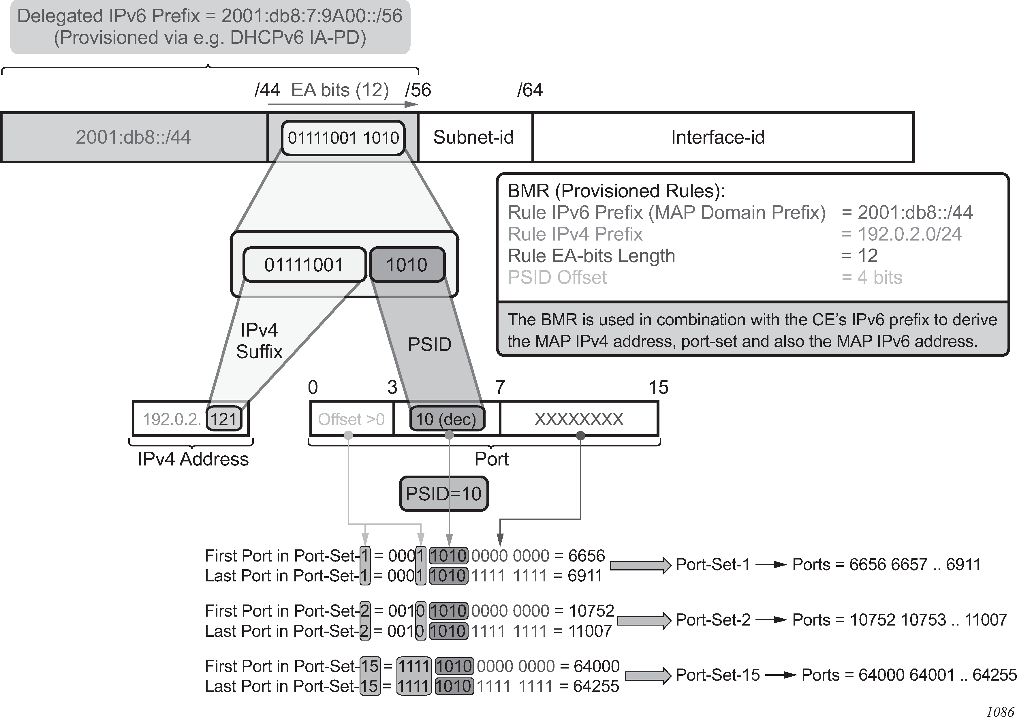
Routing considerations
MAP-T deployment scenario shows a MAP-T deployment scenario.
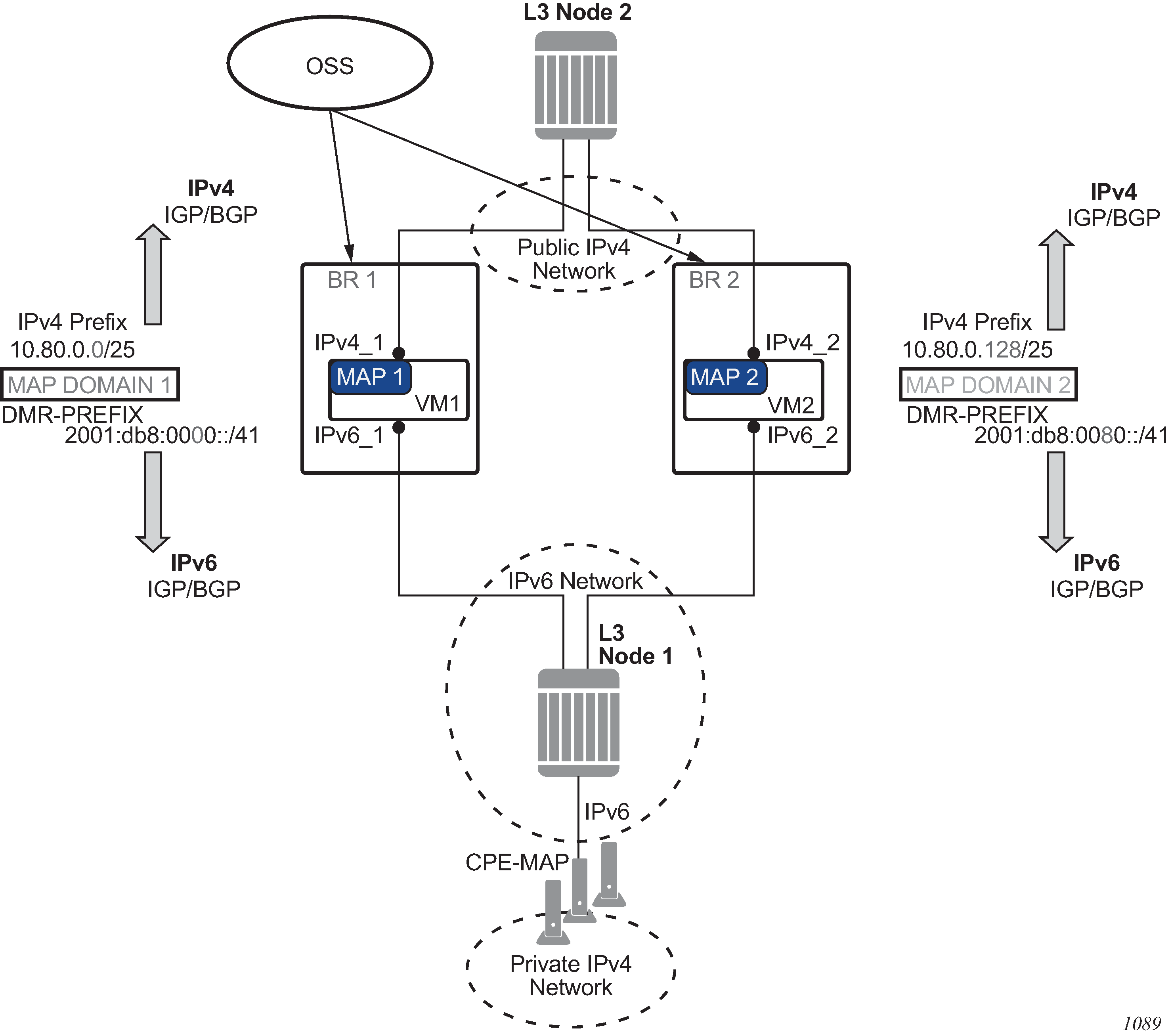
The routes related to MAP-T are:
IPv4 prefixes from the MAP-rules
These routes are advertised in the upstream direction.
DMR
This is the BR prefix for a specific domain. This route is advertised in the downstream direction.
Routes related to MAP-T are advertised through IPv4 and IPv6 routing protocols. MAP-T routes in the VSR are owned by ‟protocol nat” with a metric of 50. This can be used to configure an export routing policy when advertising MAP-T routes in IGP or BGP.
Multiple MAP-T domains can be supported in the same routing context.
Forwarding considerations in the BR
In the upstream direction, when the BR receives an IPv6 packet destined for the BR prefix, a source-based IPv6 address lookup (anti-spoofing) is performed to verify that the packet is sent by the credible CE.
In the downstream direction, a destination-based IPv4 lookup is performed. This leads to the MAP-T rule entry, which provides the information necessary to derive the IPv6 address of the destination CE.
The MAP-T forwarding function in the VSR is also responsible for:
address conversion between IPv4 and IPv6 based on the BMR rule
header translation between IPv4 and IPv6, as described in RFC 6145
In address-sharing scenarios, address translation is performed for TCP/UDP and a subset of ICMP traffic; everything else is dropped. In contrast, 1:1 and prefix-sharing scenarios are protocol agnostic.
IPv6 addresses
An IPv6 address of the MAP-T node is constructed according to RFC 7597, §5.2 and RFC 7599, §6. IPv6 address construction shows the IPv6 address of the MAP-T node.
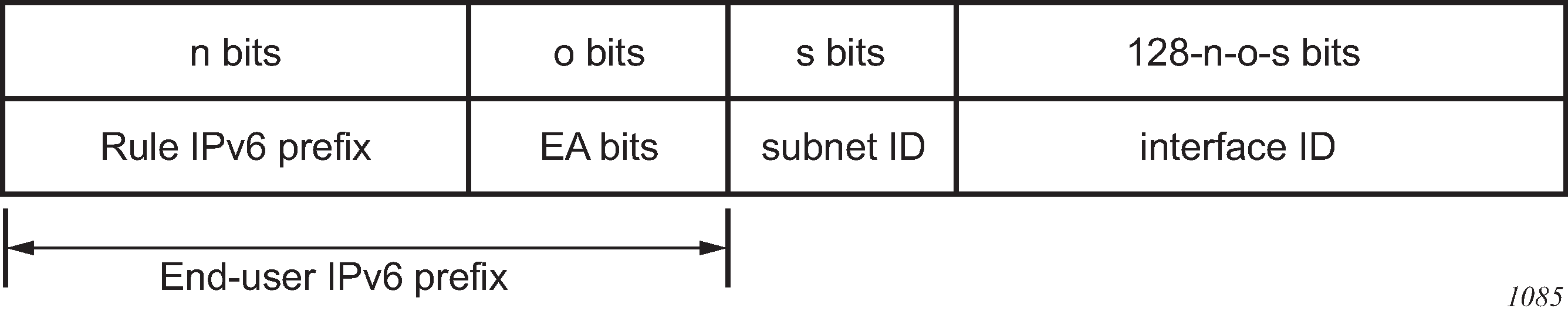
The subnet ID for a MAP node (CE) is set to 0. Node interface shows the node interface (PSID is left-padded with zeros to create a 16-bit field and the IPv4 address is the public IPv4 address assigned to the CE).
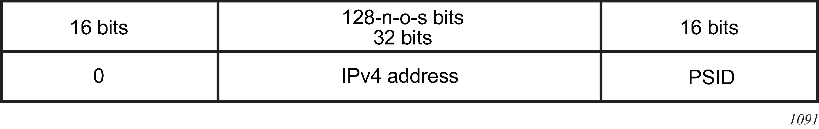
This constructed IPv6 address represents the source IPv6 address of traffic sent from the CE to BR (upstream direction), and the destination IPv6 address in the opposite direction (downstream traffic sent from the BR to the CE).
The source IPv6 address in the downstream direction is a combination of the BR IPv6 prefix and the source IPv4 address (per RFC 7599, §5.1) received in the original packet.
The destination IPv6 address in the upstream direction is a combination of the BR IPv6 prefix and the IPv4 destination address (RFC 7599, §5.1) in the original packet.
1:1 translations and IPv4 prefix translations
1:1 translations refer to the case in which each CE is assigned a distinct public IPv4 address; that is, there is no public IPv4 address sharing between the CEs. In this case, the PSID field is 0 and the sum of lengths for the IPv4 rule prefix and EA bits is 32. In other words, all the EA bits represent the IPv4 suffix. The public IPv4 address of the CE is created by concatenating the Rule IPv4 Prefix and the EA bits.
IPv4 Prefix translations refer to the case where an IPv4 prefix is assigned to a CE. In this case, the PSID field is 0 and the sum of the lengths for IPv4 rule prefix and EA bits is less than 32.
In both preceding cases, the translations are protocol agnostic; all protocols, not just TCP/UDP or ICMP, is translated.
Hub-and-spoke topology
The BR supports hub-and-spoke topology, which means that the BR facilitates communication between MAP-T CEs.
Rule prefix overlap
Rule prefix overlap is not supported because it can cause lookup ambiguity. IPv6 rule prefix overlap shows a rule prefix overlap example.

In the case where rule IPv6 prefix 1 is a subset of rule IPv6 prefix 2, the overlapping bits between the EA-bits in end user prefix 2 and the overlapping bits in rule prefix 1 (represented by the shaded sections in IPv6 rule prefix overlap) could render end-user prefixes 1 and 2 indistinguishable (everything else being the same) when anti-spoof lookup is performed in the upstream direction. This could result in an incorrect anti-spoofing lookup.
A similar logic can be applied to overlapping IPv4 prefixes in the downstream direction, where the longest prefix match always leads to the same CE, while the shortest match (leading to a different CE) is not evaluated.
BMR rules implementation example
This section examines an example MAP-T deployment with three MAP rules. The deployment assumes the following:
There are about 12,000 private IPv4 addresses that need to be translated via MAP-T.
Each such address should have approximately 4000 ports available per CE. Therefore, the IP address sharing ratio is 16:1; that is, 16 CEs share the same public IP address.
The public IPv4 addresses that are available to the operator for this translation are from three /24 subnets (10.11.11.0/24, 10.12.12.0/24 and 10.13.13.0/24).
All users (or CEs) are assigned a /60 IA-PD.
The 12,000 private IPv4 addresses (CEs) in a 16:1 sharing scenario can be covered using three /24 subnets as follows:
(3 * 2^8 * 16 = 12,288)
The IPv4 rule prefix and EA bits length per rule in this scenario are:
10.11.11.0/24 EA length: 12 bits (8 bits for the IPv4 suffix and 4 bits for PSID)
10.12.12.0/24 EA length: 12 bits (8 bits for the IPv4 suffix and 4 bits for PSID)
10.13.13.0/24 EA length: 12 bits (8 bits for the IPv4 suffix and 4 bits for PSID)
The first 6 bits of the 16 bit port-range are set to 000000 and are reserved for psid-offset (ports 0-1023 are reserved); therefore, the user-allocated port space is calculated as follows:
4000 - 64 = 4032 ports
The IPv6 rule prefix is the next parameter in the MAP rule. Determining the rule IPv6 prefix shows the relevant bits in the IPv6 address: only bits /32 to /64 are considered; the irrelevant bits of the IPv6 addresses are ignored in this example.
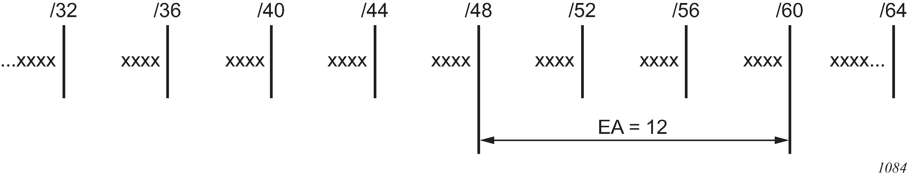
The following three rules are created in this example:
Rule 1 covers subnet 1.
Rule 2 covers subnet 2.
Rule 3 covers subnet 3.
In each of the three cases, the EA bits extend from the PD length (/60) to the IPv6 rule prefix length (/48).
The IPv6 rule prefix length is determined for each of the three rules. However, the IPv6 rule prefixes must not overlap, see sectionRule prefix overlap for more information. Non-overlapping IPv6 rule prefixes ensure that each CE is assigned a unique IA-PD. IPv6 rule prefixes describes the rules.
|
Rule 1 | Rule 1 | Rule 1 |
|---|---|---|---|
IPv6 rule prefix |
2001:db8:0000::/48- |
2001:db8:0001::/48- |
2001:db8:0002::/48- |
IPv4 rule prefix |
10.11.11.0/24 |
10.12.12.0/24 |
10.13.13.0/24 |
EA bits |
12 |
12 |
12 |
Paid-Offset |
6 |
6 |
6 |
The final step is to ensure that the DHCPv6 server hands out correct end-user prefixes (IA-PD), and the rules are also delegated.
In this example, each /48 IPv6 rule prefix supports 4,000 MAP-T CEs, where each CE can further delegate 15 IPv6 ‟subnets” on the LAN side and each CE is allocated about 4,000 ports to use in stateful NAT44.
ICMP
The following ICMPv4 messages are supported in MAP-T on the VSR; other types of ICMP messages are not supported:
ICMP query messages
These messages contain an identifier field in the ICMP header, which is referred to as the ‟query identifier” or ‟query-id” and it is used in MAP-T in the same way as the L4 ports are used in TCP or UDP. ICMP Echo Req/Rep (PING) and traceroute are examples that rely on ICMP Query messages.
ICMP error messages
These messages contain the embedded original datagram that triggers the ICMP error message. The ICMP error messages do not contain the query-id field.
The ICMP Query messages and ICMP Error messages are supported regardless of whether they are just passing through a VSR (transit messages), or are terminated or generated in or from a VSR.
The NAT-related ICMPv4 behavior is described in RFC 5508. The following NAT messages are supported in the MAP-T VSR (RFC 5508, §7, Requirement 10a):
ICMPv4 Error Message: Destination Unreachable Message (Type 3)
ICMPv4 Error Message: Time Exceeded Message (Type 11)
ICMPv4 Query Message: Echo and Echo Reply Messages (Type 8 and Type 0)
Fragmentation
The IPv6 header of the IPv4-translated packet in MAP-T can be up to 28 bytes larger than the IPv4 header (40-byte IPv6 header plus 8-byte fragmentation header versus 20-byte IPv4 header). In the case where the IPv4-to-IPv6 translated packet is larger than the IPV6 MTU, the original IPv4 packet is fragmented so that the size of the translated IPv6 packet is within IPv6 MTU. IPv6 packets are never fragmented, although they may contain the fragmentation header that carries fragmentation information related to the original IPv4 packet/fragment.
The IPv6 MTU in the VSR is configurable for each MAP-T domain. The L2 header is excluded from the IPv6 MTU.
Fragmentation in the downstream direction
All fragments of the same IPv4 packet are translated and sent toward the same CE. As the second and consecutive fragments do not contain any port information, the translation is performed based on the <SA, DA, Prot, Ident> cached flow records extracted from the IPv4 header.
Note that the VSR may further fragment an IPv4 fragment that it has received to fit it within the IPv6 MTU.
Fragmentation in the downstream direction shows downstream fragmentation scenarios.

Fragmentation in the upstream direction
In the upstream direction, the received IPv6 fragments are artifacts of the IPv4 packets being fragmented on the CP side, before they are translated into IPv6. No flow caching is performed in the upstream direction. The BR performs an anti-spoof for each fragment and if the anti-spoof is successful, the fragment is translated to IPv4. Fragmentation in the upstream direction shows the upstream fragmentation scenario.
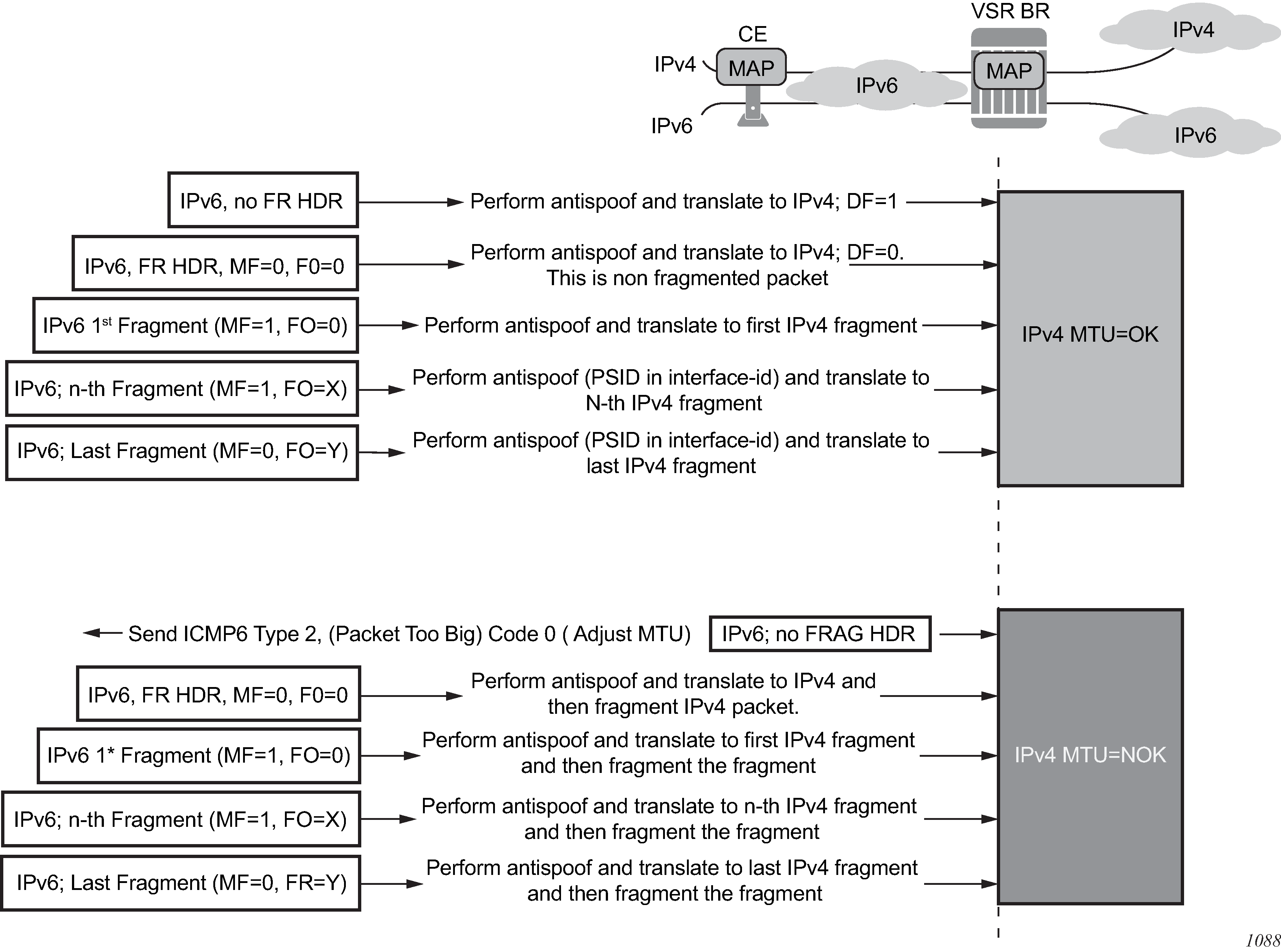
Fragmentation statistics
Fragmentation statistics can be cleared using the clear nat map frag-stats command. The following fragmentation statistics are available:
Rx Resolved Frags
This counter shows fragments that were resolved and never buffered; for example:
first fragments (MF=1, FO=0), which are always resolved by definition
non-first fragments with matching flow records
Rx Unresolved Frags
This counter shows the number of packets that were queued in the system since the last clear command was invoked. For example, packets with out-of-order fragments without a matching flow record (missing 1st fragment) can be eventually resolved and forwarded, or discarded (for example, because of timeout).
Tx Frags
This counter shows the fragments that were transmitted (Rx Resolved and Rx Unresolved that were eventually resolved) out of fragmentation logic within the VSR. There is no guarantee that the fragments are transmitted out of the system as they may be dropped on egress because of congestion or restrictions imposed by the configured filter.
Dropped Frags
This counter represents the fragments that are dropped because of fragmentation issues such as timeout, buffer full, and so on.
Buffers in Use
This counter represents the amount of buffered fragments expressed as a percentage of the maximum buffer space that can be used for fragmentation.
Max Buffers
This is a non-cumulative counter that represents the maximum number of buffers allocated since the last clear command. The counter captures the highest value of the buffers-in-use counter since the last clear command. The unit of this counter is the percentage of the total buffer space that can be used by fragmentation.
Created Flows
This is a cumulative counter that represents the total number of flow records since the last clear command was invoked. It only counts the first fragment. It represents the number of fragmented packets that were processed by the system since the last clear command. This counter does not indicate the number of flows (packets whose fragments were transmitted fully) that were actually transmitted.
Flows in Use
The counter gives an approximation of the number of flow records currently in use and the number of fragmented packets being processed at the time the counter was invoked, as a percentage.
Max Flows
A non-cumulative counter that represents the maximum number of flow records reached since the last clear command. The counter shows the highest value of the flows-in-use counter since the last clear command, as a percentage.
Flow Collisions
This counter represents the number of overlapping first fragments. For example, in the case where a flow record already exists and another first fragment for the flow is received.
Exceeded Max Timeouts
This counter shows the number of fragments that have timed out since the last clear command. The represented fragments are:
Rx unresolved (buffered) fragments that have timed out because of a missing first fragment
deleted flow-records because they have not received all fragments within the timeout period
Exceeded Max Flows
This counter represents the number of times that the flows in the system has exceeded the maximum supported value.
Exceeded Max Buffers
This counter represents the number of times that the buffers in the system has exceeded the maximum supported value.
Exceeded Max Buffers Per Flow
This counter represents the number of times that the fragment counter per flow has exceeded its limit.
Maximum Segment Size (MSS) adjust
The MSS Adjust feature is used to prevent fragmentation of TCP traffic. The TCP synchronize/start (SYN) packets are intercepted and their MSS value inspected to ensure that it conforms with the configured MSS value. If the inspected value is greater than the value configured in the VSR BR, the MSS value in the packet is lowered to match the configured value before the TCP SYN packet is forwarded.
As the end nodes governing the MSS value are IPv4 nodes, this feature is supported for IPv4 packets only.
An MSS adjust is performed in both the upstream and downstream directions.
Statistics collection
The VSR BR maintains a count of the forwarded and dropped packets/octets per MAP-T-domain per direction. The statistics are collected on ingress (upstream v6 and downstream v4) and stored in 64-bit counters.
Logging
As with any NAT operation where the identity of the user is hidden behind the NAT identity, logging of the NAT translation information is required. In the MAP-T domain, NAT logging is based on configuration changes because the user identity can be derived from the configured rules.
A system can have a large number of rules and each configured MAP rule generates a separate log. As a result, the amount of logs generated can be substantial. Logging is explicitly enabled using a log event.
A NAT log contains information about the following:
MAP type (map-t)
map-domain name
map-rule name
v6 rule-prefix
v4 rule-prefix
EA bits
psid-offset bits
associated routing context for the MAP-T rule
timestamp
A MAP rule log is generated when both of the following conditions are met:
a MAP rule is activated and deactivated in the system (administratively shutdown/no shutdown, corresponding MAP domain is associated/dissociated from the routing context, corresponding MAP domain is shutdown /no shutdown, and so on)
event tmnxNatMapRuleChange (id=2036) has been enabled in event-control
Example:
551 2016/04/22 14:56:35.44 UTC MINOR: NAT #2036 vprn220 NAT MAP
"map-type=map-t map-domain=domain-name-1 rule-name=rule-name-1 rule-prefix=2001:db8::/44 ipv4-prefix=192.168.10.0/24 ea-length=12 psid-offset=6 enabled router=vprn220 at 2016/04/22 14:56:35"
Licensing
A valid MAP-T license is required to enable the MAP-T functionality in the VSR BR. A MAP-T domain can only be instantiated with the appropriate license, which enables the following CLI command:
configure
   service
      vprn <id> customer <cust-id> create
          map-domain <domain-name>
Configuration
The MAP-T configuration consists of defining MAP-T parameters within a template. The MAP-T domain is then instantiated by applying (referencing) this template within a routing (router or VPRN) context.
Defining a MAP domain template:
configure
  service
    nat
       map-domain <domain-name> create
          [no] shutdown
          dmr-prefix <ipv6-prefix>
          tcp-mss-adjust  <segment-size>
          mtu <mtu-size>
          ip-fragmentation
             [no] v6-frag-header
          mapping-rule <rule-name>
             [no] shutdown
             rule-prefix <ipv6-prefix>
             ipv4-prefix <ipv4-prefix>
             ea-length <ea-bits-length>
             psid-offset <psid-offset-len>
          :
          mapping-rule <rule-name>
             [no] shutdown
             rule-prefix <ipv6-prefix>
             ipv4-prefix <ipv4-prefix>
             ea-length <ea-bits-length>
             psid-offset <psid-offset-len>
          :
          up to 256 rules per domain
MAP-T domain instantiation:
configure
   service vprn <id>   |  router
     nat
      map-t
         map-domain <domain-name>
MAP domain example template:
The following example shows the MAP domain template for the BMRs defined BMR rules implementation example.
configure
   service
     nat
        map-domain domain_1 create
           no shutdown
           dmr-prefix 2001:db8:0100::/64
           mapping-rule rule_1
             no shutdown
             rule-prefix 2001:db8:0000::/48
             ipv4-prefix 10.11.11.0/24
             ea-length 12
             psid-offset 6
           mapping-rule rule_2
             no shutdown
             rule-prefix 2001:db8:0001::/48
             ipv4-prefix 10.12.12.0/24
             ea-length 12
             psid-offset 6
           mapping-rule rule_3
             no shutdown
             rule-prefix 2001:db8:0002::/48
             ipv4-prefix 10.13.13.0/24
             ea-length 12
             psid-offset 6
MAP-T domain instantiation example:
The following example shows the MAP-T domain instantiation for the BMRs defined in BMR rules implementation example.
configure
   service
      vprn 10
         nat
           map-t
             map-domain domain_1
Modifying MAP-T parameters when the MAP-T domain is active
You can add new rules to an existing MAP-T domain while the MAP-T domain is instantiated and forwarding traffic. However, each rule must be in the shutdown state before any of its parameters are modified.
A MAP-T domain must be in the shutdown state to modify the dmr-prefix parameter. The remaining parameters (tcp-mss-adjust, mtu, ip-fragmentation) can be modified while the domain is active.
A MAP domain does not have to be in a shutdown state when rule modification is in progress.
Inter-chassis redundancy
MAP natively provides multi-chassis redundancy through the use of the anycast BR prefix that is advertised from multiple nodes.
As there is no state maintenance in the MAP-T BR, any BR node can process traffic for the same domain at all times. The only traffic interruption during the switch-over is for the fragmented traffic in the downstream direction being handled at the time of switchover (the flow record cache is not synchronized between the nodes).
Configuring NAT
This section provides information to configure NAT using the command line interface.
ISA redundancy
The 7750 SR supports ISA redundancy to provide reliable NAT even when an MDA fails. The active-mda-limit command allows an operator to specify how many MDAs are active in a NAT group. Any number of MDAs configured above the active-mda-limit are spare MDAs; they take over the NAT function if one of the current active MDAs fail.
A sample configuration is as follows:
configure
    isa
        nat-group 1 create
            active-mda-limit 1
            mda 1/2
            mda 2/2
            no shutdown
        exit
    exit
exit
Show commands are available to display the actual state of a nat-group and its corresponding MDAs:
show isa nat-group 1
===============================================================================
ISA NAT Group 1
===============================================================================
Admin state       : inService           Operational state : inService
Active MDA limit  : 1                   Reserved sessions : 0
High Watermark (%): (Not Specified)     Low Watermark (%) : (Not Specified)
Last Mgmt Change  : 01/11/2010 15:05:36
===============================================================================
===============================================================================
ISA NAT Group 1 members
===============================================================================
Group Member     State          Mda  Addresses  Blocks     Se-% Hi Se-Prio
-------------------------------------------------------------------------------
1     1          active         1/2  0          0          0    N  0
-------------------------------------------------------------------------------
No. of members: 1
===============================================================================
A nat-group cannot become active (no shutdown) if the number of configured MDAs is lower than the active-mda-limit.
An MDA can be configured in several nat-groups but it can only be active in a single nat-group at any moment in time. Spare MDAs can be shared in several nat-groups, but a spare can only become active in one nat-group at a time. Changing the active-mda-limit, adding or removing MDAs can only be done when the nat-group is shutdown.
Nat-groups that share spare MDAs must be configured with the same list of MDAs. It is possible to remove/add spare MDAs to a nat-group while the nat-group is admin enabled.
Configure
    isa
        nat-group 1 create
            active-mda-limit 1
            mda 1/2
            mda 2/2
            mda 3/1
            no shutdown
        exit
        nat-group 2 create
            active-mda-limit 1
            mda 1/2
            mda 2/2
            mda 3/1
            no shutdown
        exit
    exit
exit
Through show commands, it is possible to display an overview of all the nat-groups and MDAs.
show isa nat-group
===============================================================================
ISA NAT Group Summary
===============================================================================
Mda  Group 1            Group 2
-------------------------------------------------------------------------------
1/1  active             busy
2/2  busy               active
3/1  standby            standby
===============================================================================
If an MDA fails, the spare (if available) takes over. All active sessions are lost, but new incoming sessions makes use of the spare MDA.
In case of an MDA failure in a nat-group without any spare MDA, all traffic toward that MDA is black-holed.
For L2-aware NAT, the operator has the possibility to clear all the subscribers on the affected MDA (clear nat isa), terminating all the subscriber leases. New incoming subscribers make use of the MDAs that are still available in the nat-group.
NAT Layer 2-Aware configurations
The following sections provide NAT Layer 2-Aware configurations.
#--------------------------------------------------
echo "Card Configuration"
#--------------------------------------------------
    card 1
        card-type iom4-e-b
        mda 1
            mda-type m48-1gb-xp-tx
        exit
        mda 2
            mda-type isa-bb
        exit
    exit
    card 2
        card-type iom4-e-b
        mda 1
            mda-type m48-1gb-xp-tx
        exit
        mda 2
            mda-type isa-bb
        exit
    exit

#--------------------------------------------------
echo "ISA Configuration"
#--------------------------------------------------
    isa
        nat-group 1 create
            description "1 active + 1 spare"
            active-mda-limit 1
            mda 1/2
            mda 2/2
            no shutdown
        exit
    exit
#--------------------------------------------------
echo "Router (Network Side) Configuration"
#--------------------------------------------------
    router
        ...
#--------------------------------------------------
echo "NAT (Network Side) Configuration"
#--------------------------------------------------
        nat
            outside
                pool "pool1" nat-group 1 type l2-aware create
                    address-range 10.81.0.0 10.81.0.200 create
                    exit
                    no shutdown
                exit
            exit
        exit
#--------------------------------------------------
echo "Service Configuration"
#--------------------------------------------------
    service
        customer 1 create
            description "Default customer"
        exit
        ...
        vprn 100 customer 1 create
            ...
            nat
                outside
                    pool "pool2" nat-group 1 type l2-aware create
                        address-range 10.0.0.0 10.0.0.200 create
                        exit
                        no shutdown
                    exit
                exit
            exit
        exit

        vprn 101 customer 1 create
            ...
            nat
                inside
                    l2-aware
                        # Hosts in this service with IP addresses in these ranges
                        # will be subject to l2-aware NAT.
                        address 10.0.0.1/29
                        address 10.1.0.1/29
                    exit
                exit
            exit
        exit
        ...
        nat
            nat-policy "l2-aware-nat-policy1" create
                pool "pool1" router Base
            exit
            nat-policy "l2-aware-nat-policy2" create
                pool "pool2" router 100
            exit
        exit
        ...
    exit
#--------------------------------------------------
echo "Subscriber-mgmt Configuration"
#--------------------------------------------------
    subscriber-mgmt
        # Subscribers using these sub-profiles will be subject to l2-aware NAT.
        # The configured nat-policies will determine which IP pool will be used.
        sub-profile "l2-aware-profile1" create
            nat-policy "l2-aware-nat-policy1"
        exit
        sub-profile "l2-aware-profile2" create
            nat-policy "l2-aware-nat-policy2"
        exit
        ...
    exit
Large scale NAT configuration
The following sections provide Large Scale NAT configuration examples.
configure
#--------------------------------------------------
echo "Card Configuration"
#--------------------------------------------------
    card 3
        card-type iom3-xp
        mda 1
            mda-type isa-bb
        exit
        mda 2
            mda-type isa-bb
        exit
    exit
#--------------------------------------------------
echo "ISA Configuration"
#--------------------------------------------------
    isa
        nat-group 1 create
            active-mda-limit 2
            mda 3/1
            mda 3/2
            no shutdown
        exit
    exit
#--------------------------------------------------
echo "Filter Configuration"
#--------------------------------------------------
    filter
        ip-filter 123 create
            entry 10 create
                match
                    src-ip 10.0.0.1/8
                exit
                action nat
            exit
        exit
    exit
#--------------------------------------------------
echo "NAT (Declarations) Configuration"
#--------------------------------------------------
    service
        nat
            nat-policy "ls-outPolicy" create
            exit
        exit
    exit
#--------------------------------------------------
echo "Service Configuration"
#--------------------------------------------------
    service
        customer 1 create
            description "Default customer"
        exit
        vprn 500 customer 1 create
            interface "ip-192.168.113.1" create
            exit
            nat
                outside
                    pool "nat1-pool" nat-group 1 type large-scale create
                        port-reservation ports 200
                        address-range 10.81.0.0 10.81.6.0 create
                        exit
                        no shutdown
                    exit
                exit
            exit
        exit
        vprn 550 customer 1 create
            interface "ip-192.168.13.1" create
            exit
        exit
        nat
            nat-policy "ls-outPolicy" create
                pool "nat1-pool" router 500
                timeouts
                    udp hrs 5
                    udp-initial min 4
                exit
            exit
        exit
        vprn 500 customer 1 create
            router-id 10.21.1.2
            route-distinguisher 500:10
            vrf-target export target:500:1 import target:500:1
            interface "ip-192.168.113.1" create
                address 192.168.113.1/24
                static-arp 192.168.113.5 2001:db8:01:01:00:01
                sap 1/1/1:200 create
                exit
            exit
            no shutdown
        exit
        vprn 550 customer 1 create
            router-id 10.21.1.2
            route-distinguisher 550:10
            vrf-target export target:550:1 import target:550:1
            interface "ip-192.168.13.1" create
                address 192.168.13.1/8
                sap 1/2/1:900 create
                    ingress
                        filter ip 123
                    exit
                exit
            exit
            nat
                inside
                    nat-policy "ls-outPolicy"
                exit
            exit
            no shutdown
        exit
    exit
exit all
NAT configuration examples
The following output displays example configurations.
VPRN service example:
configure service vprn 100 nat
                inside
                    nat-policy "priv-nat-policy"
                    destination-prefix 0.0.0.0/0
                    dual-stack-lite
                        subscriber-prefix-length 128
                        address 2001:db8:470:1F00:FFFF:190
                            tunnel-mtu 1500
                        exit
                        no shutdown
                    exit
                    redundancy
                        no peer
                        no steering-route
                    exit
                    subscriber-identification
                        shutdown
                        no attribute
                        no description
                        no radius-proxy-server
                    exit
                    l2-aware
                    exit
                exit
                outside
                    no mtu
                exit
Router NAT example:
configure router nat
            outside
                no mtu
                pool "privpool" nat-group 3 type large-scale create
                    no description
                    port-reservation blocks 128
                    port-forwarding-range 1023
                    redundancy
                        no export
                        no monitor
                    exit
                    subscriber-limit 65535
                    no watermarks
                    mode auto
                    address-range 10.0.0.5 10.0.0.6 create
                        no description
                        no drain
                    exit
                    no shutdown
                exit
                pool "pubpool" nat-group 1 type large-scale create
                    no description
                    port-reservation blocks 1
                    port-forwarding-range 1023
                    redundancy
                        no export
                        no monitor
                    exit
                    subscriber-limit 65535
                    no watermarks
                    mode auto
                    address-range 192.168.8.241 192.168.8.247 create
                        no description
                        no drain
                    exit
                    no shutdown
                exit
            exit
Service NAT example:
configure service nat
            nat-policy "priv-nat-policy" create
                alg
                    ftp
                    rtsp
                    sip
                exit
                block-limit 4
                no destination-nat
                no description
                filtering endpoint-independent
                pool "privpool" router Base
                no ipfix-export-policy
                port-limits
                    forwarding 64
                    no reserved
                    no watermarks
                exit
                priority-sessions
                exit
                session-limits
                    max 65535
                    no reserved
                    no watermarks
                exit
                timeouts
                    icmp-query min 1
                    sip min 2
                    no subscriber-retention
                    tcp-established hrs 2 min 4
                    tcp-syn sec 15
                    no tcp-time-wait
                    tcp-transitory min 4
                    udp min 5
                    udp-initial sec 15
                    udp-dns sec 15
                exit
                no tcp-mss-adjust
                no udp-inbound-refresh
            exit
            nat-policy "pub-nat-policy" create
                alg
                    ftp
                    no rtsp
                    no sip
                exit
                block-limit 1
                no destination-nat
                no description
                filtering endpoint-independent
                pool "pubpool" router Base
                no ipfix-export-policy
                port-limits
                    no forwarding
                    no reserved
                    no watermarks
                exit
                priority-sessions
                exit
                session-limits
                    max 65535
                    no reserved
                    no watermarks
                exit
                timeouts
                    icmp-query min 1
                    sip min 2
                    no subscriber-retention
                    tcp-established hrs 2 min 4
                    tcp-syn sec 15
                    no tcp-time-wait
                    tcp-transitory min 4
                    udp min 5
                    udp-initial sec 15
                    udp-dns sec 15
                exit
                no tcp-mss-adjust
                no udp-inbound-refresh
            exit
Configuring VSR-NAT
This section provides information about the VSR-NAT functionality, including licensing requirements, statistics collection, and examples of show command output.
VSR-NAT licensing
Appropriate licensing is required to enable the VSR-NAT functionality in the system. However, no further licensing enforcement is performed based on resource utilization, such as the consumed bandwidth or the number of NAT bindings.
The following NAT-related functionality is enabled through licensing:
LSN (LSN44, DS-Lite, and NAT64)
L2-Aware NAT
UPnP
geo-redundancy
You can use the CLI or MIB on VSR-NAT to get more information about the number of LSN bindings and LSN bandwidth.
NAT licenses required to unlock NAT functionality describes the licenses required to unlock the VSR-NAT functionality.
| NAT license title | Functionality enabled | License purchased |
|---|---|---|
LSN |
LSN Pool
|
The following two scaling licenses are required:
You must purchase both licenses to enable the LSN functionality. |
L2AWARE |
L2Aware Pool
|
Purchase the L2-Aware license to enable the functionality. The LSN scaling license is not required. Note: The L2-Aware NAT functionality can only be
used with the VBNG.
|
UPnP |
UPnP commands: configure subscriber-mgmt sub-profile sub-prof-name upnp-policy upnp-pol-name |
Purchase the UPnP license to enable the functionality. Note: The UPnP functionality can only be used with
the L2-Aware NAT.
|
GEO REDUNDANCY |
Geo-redundancy Pool
|
Purchase the Geo Redundancy license to enable the functionality. |
Statistics collection For LSN bindings
A NAT subscriber is an internal entity whose true identity is hidden outside the network. The NAT subscriber is represented by a binding that is a set of stateful mappings between the internal and external representations of the subscriber. From the licensing perspective, the terms ‟NAT bindings” and ‟NAT subscribers” can be used interchangeably.
VSR-NAT collects the number of LSN subscribers for licensing purposes; the L2-Aware NAT subscribers are excluded from this count. An LSN subscriber is defined as follows:
Large Scale NAT44 (or CGN)
The subscriber is an internal IPv4 address.
DS-Lite
The subscriber is identified by the CPE IPv6 address (B4 element) or an IPv6 prefix. The selection of the address or prefix as the representation of a DS-Lite subscriber is configuration-dependent.
NAT64
The subscriber is an IPv6 address.
The number of LSN subscribers (LSN44, DS-Lite, and NAT64) in VSR-NAT is sampled every hour on the hour (for example, at 00:00 am, 01:00 am, 02:00 am, and so on). Each sample is a snapshot of the number of subscribers at the time that the statistics are collected.
The CLI can be used to view the following information:
24 samples (one per hour) in the current day
Maximum value for each of the last 7 days
Average value for each of the last 7 days
Maximum value since the system booted
For the list of CLI commands available for use, see VSR-NAT show command examples.
Statistics collection for LSN bandwidth
The measurement of LSN bandwidth includes translated packets and octets in the upstream and downstream direction. Packets that are rejected for any reason and traffic carrying logging information are both excluded from the statistics.
LSN bandwidth statistics for VSR-NAT are collected every 10 minutes. The bandwidth is derived as a difference in octet count between the two consecutive collection intervals, divided by a 10 minute interval. There is no bandwidth differentiation per LSN type (LSN44, DS-Lite, and NAT64) or per direction. Aggregate bandwidth values per node are maintained in kb/s units. L2-Aware NAT and WLAN gateway statistics are not included in the statistics collection.
The CLI can be used to view the following LSN bandwidth information:
144 bandwidth values for the current day (bandwidth statistics are collected every 10 minutes)
Maximum bandwidth value for each of the last 7 days
Average bandwidth value for each of the last 7 days
Maximum bandwidth value since the system booted
For the list of CLI commands available for use, see VSR-NAT show command examples.
VSR-NAT show command examples
The following CLI commands are available for use:
-
show system license-statistics 24-hours application nat
show system license-statistics week application nat
show system license-statistics peak application nat
The following output shows examples of NAT statistics.
Weekly display example:
*A:Dut-A>show system license-statistics week application nat
=====================================================================
week license statistics for nat
========================================================================
index       time                average              peak
---------------------------------------------------------------------
LSN subscribers
1           2016/02/01 00:00:00 370                  456
2           2016/01/31 00:00:00 375                  512
3           2016/01/30 00:00:00 374                  510
4           2016/01/29 00:00:00 373                  478
5           2016/01/28 00:00:00 360                  450
6           2016/01/27 00:00:00 370                  496
7           2016/01/26 00:00:00 373                  503
LSN bandwidth
1           2016/02/01 00:00:00 12472623             12472623
2           2016/01/31 00:00:00 12472623             12472623
3           2016/01/30 00:00:00 12472623             12472623
4           2016/01/29 00:00:00 12472623             12472623
5           2016/01/28 00:00:00 12472623             12472623
6           2016/01/27 00:00:00 12472623             12472623
7           2016/01/26 00:00:00 12472623             12472623
---------------------------------------------------------------------
No. of license statistics entries: 14
=====================================================================
24-hour display example:
*A:Dut-A# show system license-statistics 24-hours application nat
========================================================================
24 hours license statistics for nat
========================================================================
index       time                value
------------------------------------------------------------------------
LSN subscribers
1           2016/06/29 19:00:00 512
2           2016/06/29 20:00:00 512
LSN bandwidth
1           2016/06/29 18:10:00 0
2           2016/06/29 18:20:00 0
3           2016/06/29 18:30:00 0
4           2016/06/29 18:40:00 2996286
5           2016/06/29 18:50:00 12472524
6           2016/06/29 19:00:00 12472424
7           2016/06/29 19:10:00 12471020
8           2016/06/29 19:20:00 12471980
9           2016/06/29 19:30:00 12471566
10          2016/06/29 19:40:00 12471881
11          2016/06/29 19:50:00 12472116
12          2016/06/29 20:00:00 12472623
------------------------------------------------------------------------
No. of license statistics entries: 14
========================================================================
Peak display example:
========================================================================
*A:Dut-A# show system license-statistics peak application nat
========================================================================
peak license statistics for nat
========================================================================
                                      time                peak
------------------------------------------------------------------------
LSN subscribers                       2016/06/29 19:00:00 512
LSN bandwidth                         2016/06/29 20:00:00 12472623
------------------------------------------------------------------------
No. of license statistics entries: 2
========================================================================
NAT statistics output fields describes the NAT statistics output fields.
| Label | Description |
|---|---|
Index |
The entry number of the displayed value. A weekly display contains 7 entries, one for each of the last 7 days. A 24-hour display can contain up to 24 values for NAT subscribers (statistics are collected hourly) and 144 values for NAT bandwidth (statistics are collected every 10 minutes). |
Time |
The timestamp of the statistics collection. The bandwidth is averaged in 10 minute intervals. Consequently, bandwidth value at a specific time represents the average bandwidth for the last 10 minute period. |
Value |
The value for the number of NAT subscribers at a specific time, or the average bandwidth in kb/s for the last 10 minute period. |
Average |
In the weekly display, the average daily value for the number of NAT subscribers or the NAT bandwidth. |
Peak |
In the weekly display, the daily peak value for the number of NAT subscribers or the NAT bandwidth. |
VSR scaling profiles on BB-ISA
Scaling profiles on the VSR
To meet flexible scaling requirements in common compute platforms, operators can use the CLI to select VSR-NAT scaling profiles that correspond to the amount of memory allocated in the VM.
The following scaling profiles have predefined upper scaling limits and are available for VSR-NAT and IPv6 FW:
profile1 is a lower scaling profile.
profile2 is a higher scaling profile.
The default scaling profile is profile1.
Contact your Nokia representative for more information about NAT scaling figures in each profile.
For the number of required CPU control cores on a VSR-I in relation to profiles, see to the Sysinfo section in the Virtualized Service Router Installation and Setup Guide.
For the amount of required memory on VSR-I in relation to profiles, see Software Release Notes, section VM Memory Requirements by Function Mix.
Scaling profiles are applied under the following CLI hierarchy:
Classic CLI
*A:cses-V22# configure isa
*A:cses-V22>config>isa# nat-group 1 create
*A:cses-V22>config>isa>nat-group# scaling-profile
  - scaling-profile <scaling-profile-id>
 <scaling-profile-id> : {profile1|profile2}
MD-CLI
*[pr:/configure isa nat-group 1]
A:admin@cses-V27# scaling-profile ?
 scaling-profile <keyword>
 <keyword>  - {profile1|profile2}
 Default    - profile1
    Scaling profile for the NAT group
    Warning: Modifying this element toggles
    'configure isa nat-group 1 admin-state' automatically for the new value to
    take effect.
    Warning: Modifying this element clears ISA state, such as flow state, for
    the new value to take effect.
*[pr:/configure isa nat-group 1]
Scale profile modification
A scaling profile can be changed only when the NAT group is in a shut down state. After the scaling profile is changed and the NAT group is activated (no shutdown), the system tries to allocate necessary memory. If successful, the vISA transitions inservice; if unsuccessful (for example, if there is not enough memory in the system), the NAT group remains in the shut down state.
Without sufficient resources to accommodate the required scaling profile, the vMDA where the vISA resides transitions into a failed state, followed by logs describing the failure:
33 2018/05/28 09:36:30.484 UTC MAJOR: CHASSIS #2001 Base Mda 1/1
"Class MDA Module : failed, reason: Insufficient memory to boot"

36 2018/09/18 14:13:02.426 UTC MAJOR: CHASSIS #2001 Base Mda 1/1
"Class MDA Module : failed, reason: Insufficient mgmt cores to boot"
NAT scaling profiles on ESA
Scaling profiles for NAT on ESA
NAT on ESA offers two scaling profiles, each of them adapted to the amount of memory allocated to the VM.
profile1
A lower scaling profile that requires 8 CPU cores and 32 GB of DRAM memory per ESA-VM.
profile2
A medium scaling profile that requires 11 CPU cores and 96 GB of DRAM memory per ESA-VM.
profile3
A high scaling profile that requires 15 CPU cores and 115 GB of DRAM memory per ESA-VM.
The default scaling profile is profile1.
Contact your Nokia representative for more specific information about the NAT scaling figures in each profile.
Scaling profiles are configurable under the following CLI hierarchy:
Classic CLI
*A:cses-V22# configure isa
*A:cses-V22>config>isa# nat-group 1 create
*A:cses-V22>config>isa>nat-group# scaling-profile
  - scaling-profile <scaling-profile-id>
 <scaling-profile-id> : {profile1|profile2|profile3}
MD-CLI
*[pr:/configure isa nat-group 1]
A:admin@cses-V27# scaling-profile ?
 scaling-profile <keyword>
 <keyword>  - (profile1|profile2|profile3)
 Default    - profile1
    Scaling profile for the NAT group
    Warning: Modifying this element toggles
    'configure isa nat-group 1 admin-state' automatically for the new value to
    take effect.
    Warning: Modifying this element clears ISA state, such as flow state, for
    the new value to take effect.
*[pr:/configure isa nat-group 1]
Scale profile modification
A scaling profile can be changed using CLI only when all ESA-VMs in a NAT group are removed from the configuration.
For example, in the following case, transitioning from profile2 to profile1 is not possible until esa-vm 1/1 is removed from the CLI:
config
   isa
    nat-group 1
      esa-vm 1/1
        scaling-profile profile2
config>isa>nat-group# scaling-profile profile1
MINOR: BBGRPMGR #1052 Cannot change scale-profile with MDAs or ESA-VMs provisioned
Expanding a NAT group
Adding or removing an MDA from a NAT group affects all currently active subscribers and may invalidate existing static port forwards and mappings configured in deterministic NAT.
Store configurations offline before removing the configuration as part of the NAT group modification process that is described in the following information. You can restore the configuration to the node after the change is complete.
The procedure to add or remove an MDA from a NAT group is described in the following information.
-
Administratively disable deterministic prefix policies and delete their mappings. Perform this for every deterministic prefix and their mapping used in a NAT group in which the size is modified. Store the deterministic mapping configuration offline before removing it and then reapply after the change.When the NAT group size is modified and the deterministic mappings reapplied, the commit may fail. If the commit fails, you must create a new mapping. Use the following command to create a new mapping:
tools perform nat deterministic calculate-mapsStatic port forwards configurations created with the tools command are automatically deleted during the commitment of the modified NAT group.
-
Commit the changes.
-
Change the active and failed MDA limit.
-
Commit the changes.
-
Re-apply deterministic mappings and static port forwards.
Adding and removing an MDA from a NAT group in the classic CLI:
-
Shut down the NAT group.
-
Remove all statically configured large-scale subscribers (such as deterministic, LI, debug, and subscriber-aware) in a NAT group that is being modified.
-
A static port forward configuration created via the tools commands is automatically deleted.
-
Manually delete any static port forward configurations creates via classic CLI.
-
Shut down and remove the deterministic policies.
-
Delete NAT policy references in all inside routing contexts associated with the NAT group that is being modified.
-
Reconfigure the active and failed-mda-limit options.
-
Use the following command to enable the NAT group.
no shutdown -
Restore previously removed NAT group references in all of the inside routing contexts associated with the modified NAT group.
-
Reapply the subscriber-aware and deterministic subscribers (prefixes and maps), static port-forwards, LI, and debug.