G.8031 Protected Ethernet Tunnels
G.8031 Protected Ethernet Tunnels is supported only on the 7450 ESS and 7750 SR.
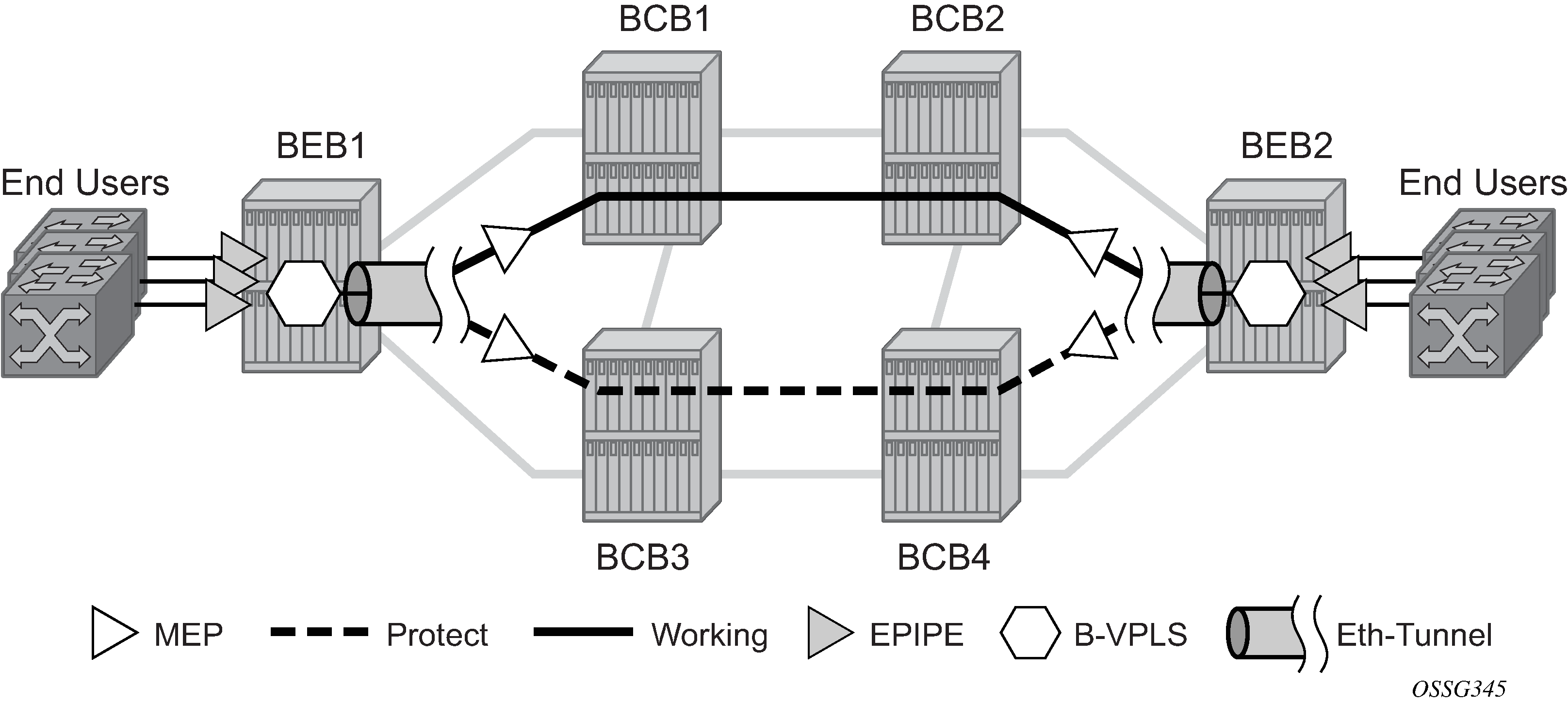
The Nokia implementation of Ethernet Tunnels offers ITU-T G.8031 specification compliance to achieve 50 ms resiliency for failures in a native Ethernet backbone for native Layer 2 networks.
Ethernet Automatic Protection Switching (APS) as defined in ITU-T recommends G.8031 provides a linear 1:1 or 1+1 protection switching mechanism for VLAN-based Ethernet networks. The OS implementation of G.8031 supports 1:1 linear protection through implementation of point-to-point Ethernet Tunnels providing a working and protecting Ethernet circuit, where the path providing the protection is always available through health-monitoring. The 1:1 model is common practice for packet based services because it makes best use of available bandwidth.
Within each path, Y.1731 Maintenance Entity Group (MEG) Endpoints (MEPs) are used to exchange APS-specific information (specifically to co-ordinate switchovers) as well as optionally fast Continuity Check Messages (CCM) providing an inherent fault detection mechanism as part of the protocol. Failure detection of a working path by one of the mechanisms triggers to move from working to protecting circuits. Upon failure, re-convergence times are a dependent on the failure detection mechanisms. In the case of Y.1731, the CCM transmit interval determines the response time. The OS supports message timers as low as 10 milliseconds so the restoration times are comparable to SONET/SDH. Alternatively, 802.3ah (Ethernet in the First Mile) or simple Loss of Signal can act as a trigger for a protection switch where appropriate.
Revertive or non-revertive behavior can be configured based on service provider environment. Revertive behavior is commonly deployed because it restores the traffic to a predictable state.
Ethernet APS can be configured on any port configured for access mode using dot1q or Q-in-Q encapsulation enabling support for Ethernet APS protected services on the service edge toward the customer site, or within the Ethernet backbone. E-Line, E-LAN, and E-Tree services can be afforded Ethernet APS protection and, although the Ethernet Tunnel providing the protection has a working/protecting path that is presented to the service as a single logical entity to the service layer. The intention of this is to cause minimum disruption to the service during Ethernet APS failure detection and recovery.
In the implementation, the Ethernet tunnel is a logical interface for a SAP defined Layer 2 service similar to a LAG. The implementation offers ITU G.8031 1:1 compliance as well as some added capabilities such as fate sharing and emulated LAG support. Other added capabilities include:
synchronization between services such that both send and receive on the same Ethernet path in stable state
revertive/non-revertive choices
emulated-LAG coexistence
It is important that the configuration for the various services does not change when a new Ethernet tunneling type is introduced on the backbone side. This is achieved by using a SAP to map the eth-tunnel object into service instance.
The member port and control tag defined under each eth-tunnel path are then used for encapsulating and forwarding the CCMs and the G.8031 PDUs used for protection function, the latter frames being sent only on the secondary path. The configuration of the active path is also used to instantiate the SAP object in the forwarding plane.
If a failure of a link or node affects the primary eth-tunnel path, the services fail to receive the CC messages exchanged on that path or receive a fault indication from the link layer OAM module.
For fault detection using CCMs, a number of 3.5 CC intervals plus a configurable hold-off timer must be missed for a fault to be declared on the associated path. The latter mechanism is required to accommodate the existence of additional 50 ms resiliency mechanism in the optical layer. After it received the fault indication, the protection module declares the associated path down, then sends an indication to the remote protection module to switch the transmit direction to the backup path.
To address unidirectional failures, the RDI bit is set in CC messages transmitted in the reverse direction upon detection of failure at the receiving service. The same applies for link layer OAM. Until the protection switch indication arrives from the remote node, the local node continues to receive frames from both primary and backup paths to avoid the loss of in-flight packets.
In case of direct connectivity between the nodes, there is no need to use Ethernet CCM messaging for liveliness detection. Link level detection mechanisms like LoS (Loss of Signal) or IEEE 802.3ah link layer OAM can be used to detect link or nodal failure. This can be achieved by not provisioning a MEP on the primary path.
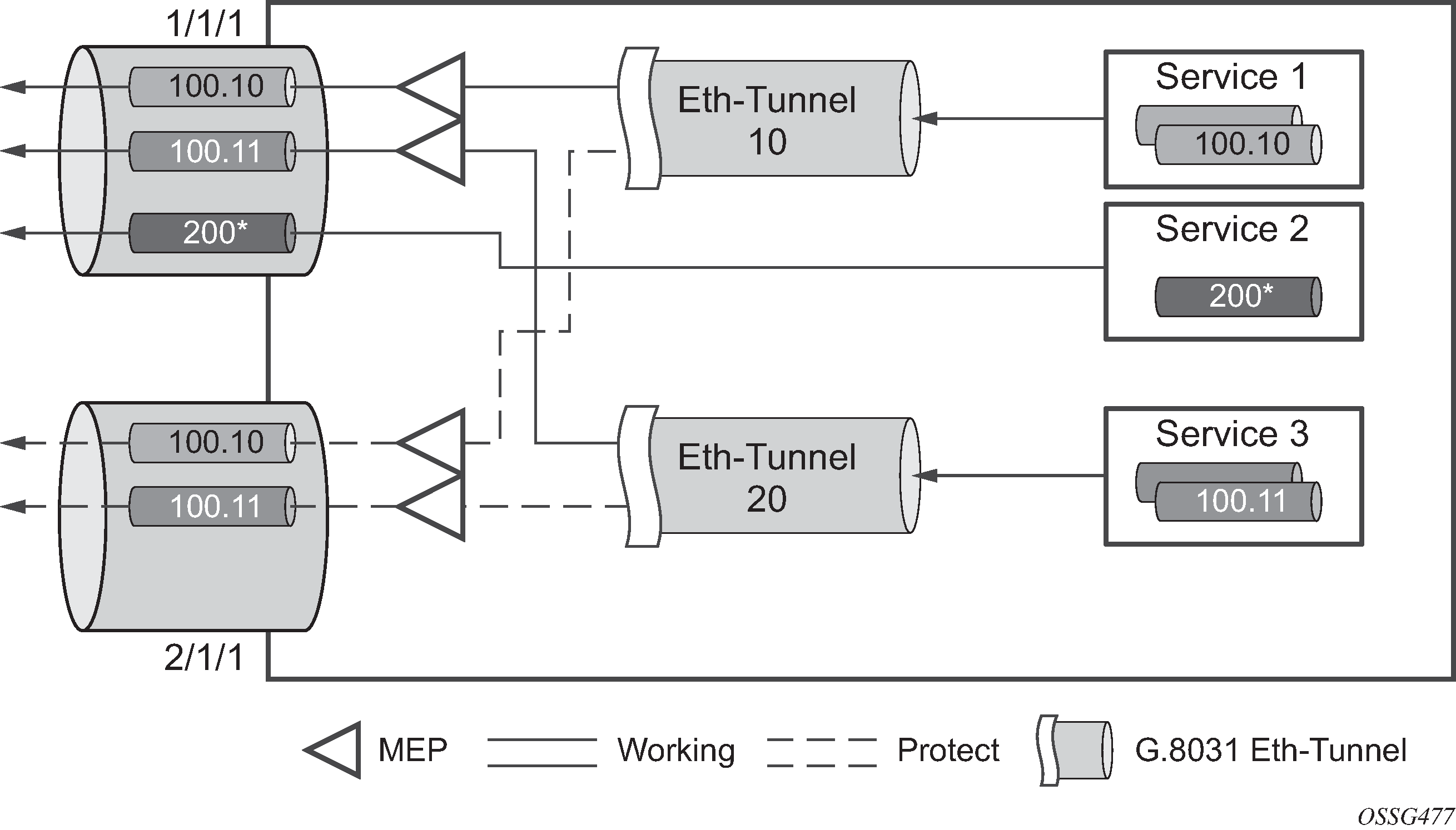
Using the Ethernet Tunnel as a building block for Ethernet APS protection it is possible to provide different protection schemes with different fate-dependency; or indeed to mix protected and non-protected services on the same physical port.
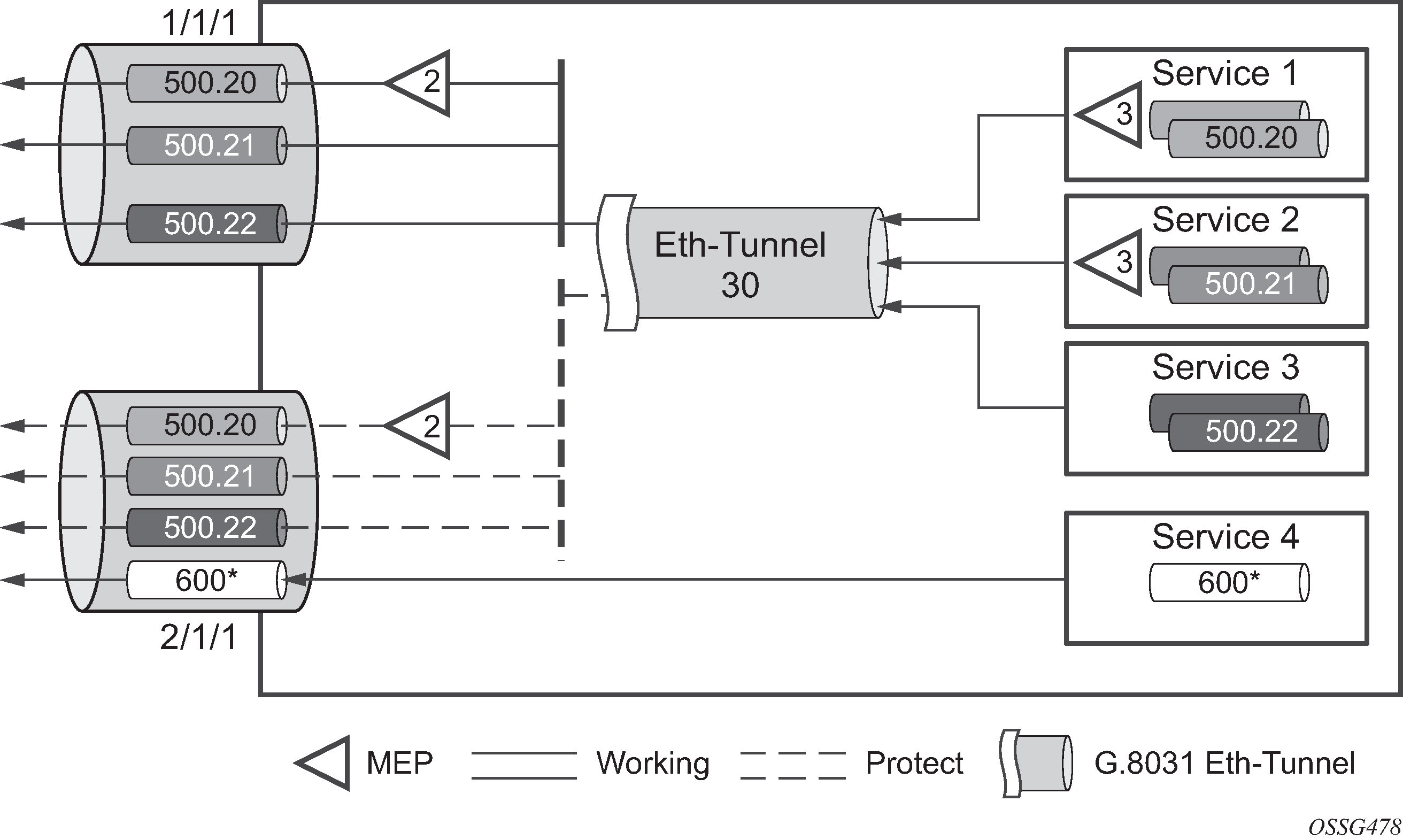
The simplest model is the fate-independent model where each Ethernet Tunnel supports its own protection using Y.1731 CCMs for example. In this case a single VLAN Tag may be used for control and data traffic. In cases where Ethernet Tunnels can be guaranteed to share a common physical path, it is possible to implement a fate-sharing model. This approach provides the advantage of reducing the amount of Ethernet OAM signaling because only one control tag determines the fate of many user tags.
Epipe using BGP-MH site support for Ethernet tunnels (see the7450 ESS, 7750 SR, 7950 XRS, and VSR Layer 2 Services and EVPN Guide for more information) offers an enhancement to Ethernet tunnels enabling an Ethernet edge device using G.8031 to support multi-chassis redundancy for Epipe services. The G.8031 device configuration is standard on the Ethernet edge device, but the active link is controlled by BGP-multihoming just as with VPLS services. This Epipe feature offers a standards-based alternative for multihomed access.
One of the advantages of access redundancy using Ethernet APS is that because it operates at the VLAN level protection mechanisms can be varied between services supported on the physical port. For example, it is possible to provide a protected service for ‟Premium” customers and also provide non-protected services for ‟Standard” users on the same physical port.
OAM considerations
Ethernet CFM can be enabled on each individual path under an Ethernet tunnel. Only down MEPs can be configured on each of them and CCM sessions can be enabled to monitor the liveliness of the path using interval as low as 10 msec. Different CCM intervals can be supported on the primary and secondary paths in an Ethernet tunnel.
MEPs can still be configured under the services independent of the Ethernet Tunnels.
The following rules control the interaction between the MEP defined under the eth-tunnel path and the MEP defined in the service:
The down MEPs configured on the eth-tunnel paths must be lower level than any down.
MEPs configured on the associated SAP. The same applies for Virtual MEPs associated with services such as BVPLS. Checks are provided to prevent the user from configuring anything that violates the above rule. An error message is generated to indicate the mismatch.
Other service MEPs (up direction, down higher levels) are allowed with no restriction.
Any down MEP on the associated SAP transmits only over the active path entity.
QoS considerations
When Ethernet tunnel is configured on two member ports located on different IOMs, the SAP queues and virtual schedulers are created with the actual parameters on each IOM.
The protection mode '8031-1to1' (default) activates only the primary path at any point in time, guaranteeing the use of the needed QoS resources.
Ethernet tunnel CC messages transmitted over the SAP queues using the default egress QoS policy use NC (network class) as a forwarding class. If user traffic is assigned to the NC forwarding class, it competes for the same bandwidth resources with the Ethernet CCMs. As CCM loss could lead to unnecessary bouncing of the Ethernet tunnel, congestion of the queues associated with the NC traffic should be avoided. The operator must configure different QoS Policies to avoid congestion for the CCM forwarding class by controlling the amount of traffic assigned into the corresponding queue.
Mirroring and Lawful Intercept considerations
Mirroring and Lawful Intercept (LI) cannot use the eth-tunnel as a source. Also, a SAP configured on an eth-tunnel cannot be used as mirror destination. The CLI blocks the above options. The SAP configured on the eth-tunnel, a filter associated with it and the member ports in the eth-tunnel>path context can be used as mirror and LI source.
Support service and solution combinations
The Ethernet tunnels are supported Layer 2 service VLL, VPLS and B-VPLS instances. The following considerations apply:
Only ports in access or hybrid mode can be configured as eth-tunnel path members. The member ports can be located on the same or different IOMs or MDAs.
Dot1q and QinQ ports are supported as eth-tunnel path members.
The same port cannot be used as member in both a LAG and an Ethernet Tunnel but LAG emulation is supported.
A mix of regular and multiple eth-tunnel SAPs and pseudowires can be configured in the same services.
Split horizon groups in VPLS and BVPLS are supported on eth-tunnel SAPs. The use of split horizon groups allows the emulation of a VPLS model over the native Ethernet core, eliminating the need for P-MSTP.
LAG Emulation offers another method offering MSTP or P-MSTP over Ethernet Tunnels.
MC-LAG access multi-homing into services is supported in combination with Ethernet tunnels.
LAG emulation using Ethernet tunnels
Ethernet Tunnels can provide G.8031 Ethernet APS protection as described in G.8031 Protected Ethernet Tunnels, or they can operate in a load-sharing manner providing an emulated LAG function. Moreover, as multiple Ethernet Tunnels can be provisioned on the same physical links, it is possible that two physical links could support one or more Ethernet Tunnels supporting APS protection for protected services whilst concurrently supporting one or more Ethernet Tunnels in load-sharing mode for non-protected services.
When Ethernet Tunnels have the protection type set to load-sharing, the precedence is configured to secondary, making the tunnels equal to implement load-sharing capability. A path threshold parameter allows the load-sharing group to be declared down if the number of paths drops equal to or lower than the threshold value. The ‛lag-emulation’ context provides access to conventional LAG parameters such as the adapt-qos mode (link, port-fair or distributed bandwidth distribution) and per-fp-ing-queuing to ensure that only one ingress queue is instantiated for every physical link supported on the same FP complex.
A typical use case for LAG emulation is to allow unprotected Ethernet services to capitalize on the LAG capability. RSTP and MSTP can also be used to network VPLS or B-VPLS over the Ethernet tunnels. LAG Emulation is also recommended when you use BGP-MH site support for Ethernet tunnels.