BIER
BIER overview
Bit Indexed Explicit Replication (BIER) architecture allows optimal forwarding of multicast packets without requiring a legacy multicast protocol to build multicast trees or for intermediate routers to maintain any per-multicast flow state. This provides a simplified control plane because BIER information is distributed using underlay IGP.
The following terms are used in BIER:
Bit Forwarding Router (BFR)
A BFR is a router supporting BIER with a unique BFR prefix and optionally, a BIER ID assigned by the operator. A BFR establishes BFR adjacencies (IGP or SDN-programmed), computes the BIER routing table, and forwards or replicates BIER packets.
BIER domain and sub-domain (SD)
A BIER domain is a connected set of BFRs, each with a unique BFR ID. A BIER domain can be divided into sub-domains for scalability without a linear increase in size of the BIER header. For example, in IS-IS, a BIER sub-domain is IS-IS multi topology, where ipv4-unicast is a single sub-domain and ipv4-multicast is another sub-domain.
Sub-domains provide minimum traffic engineering and separation of services.
Bit Forwarding Ingress Router (BFIR)
A BFIR is the first PE in a BIER domain entered by a multicast packet. The BFIR adds a BIER header and forwards the packet using the BIER routing table.
Bit Forwarding Egress Router (BFER)
A BFER is the last PE that processes a BIER packet in a BIER domain. The BFER removes the BIER header before forwarding the packet. This is the only PE that requires a BIER ID as it is a PE with receiver connectivity.
Transit Bit Forwarding Router (transit BFR)
A transit BFT is a router in the BFR domain that is not a BFIR or a BFER that forwards the packet using the best path.
SR OS does not support multicast MPLS packets over an IGP shortcut. This includes BIER MPLS encapsulation. IGP shortcuts can be configured on SR OS for unicast and installed in the RIB or FIB, but BIER is not resolved over the IGP shortcut. If an IGP shortcut is used for unicast resolution, an IPv4-multicast MT can be used to create a separate MT for BIER without the IGP shortcut.
BIER hardware
BIER is only supported on FP4 and FP5 network interfaces. BIER is not supported on FP3 or earlier cards, or on access interfaces.
If a chassis has a mix of FP3, FP4, and FP5 network ports, BIER is signaled on all FP3, FP4, and FP5 interfaces that are part of the IS-IS. From a control plane perspective, BIER TLVs are advertised using IS-IS on FP3, FP4, and FP5 interfaces. The BIER forwarding table is not downloaded to FP3 cards. Therefore, there is no BIER packet forwarding or processing on these cards. If IGP chooses FP3 L3 interfaces, there are BIER forwarding issues. An event log is generated if an FP3 is part of the BIER sub-domain.
BIER-encapsulated multicast traffic can egress only on FP4 or FP5 interfaces. Non-FP4 or non-FP5 egress interfaces do not forward BIER-encapsulated multicast traffic.
BIER IMPM
BIER supports IMPM and all the IMPM rules apply to BIER also. Users can use IMPM to optimize and increase BIER throughput.
BIER ECMP
BIER supports ECMP/LAG. SR OS only uses the smallest IP address in the ECMP/LAG group to resolve the BFRs.
After an ECMP switch, IGP must download the BIER forwarding table to the new interface or card so BIER ECMP does not have a sub-millisecond recovery. The recovery time is in line with IGP convergence time.
BIER redundancy and resiliency
If BIER Fast Reroute (FRR) is not enabled, when there is a failure on the primary next-hop BIER does not switch to the protection next-hop (LFA) even if one exists. After the failure, BIER waits for IGP to converge and a new next-hop to be available, which means that traffic interruption is equal to the IGP convergence time. LFA is still configurable when BIER is enabled and can be used for other IP and MPLS functionality.
If BIER FRR is enabled, BIER uses the available underlay Loop-Free Alternates (LFA) to provide link protection to neighbors and the recovery time from link failure is less than the IGP convergence time.
BIER FRR
BIER FRR uses basic LFA only; it cannot use TI-LFA or remote-LFA. Also, currently BIER FRR only supports ISIS.
Use the commands in the following context to configure LFA:
- MD-CLI
configure router isis loopfree-alternate - classic
CLI
configure router isis loopfree-alternates
When FRR is enabled, link protection is enabled for all BIER neighbors that can find an underlay LFA. The neighbor BFR label is pushed first. Use the following command to enable BIER FRR.
configure router bier fast-rerouteUse the following command to display BIER routing information for the sub-domain.
show router bier routing sub-domain 0In the following output example, next-hop 10.20.1.4 is protected through 10.20.1.2 using a basic LFA.
BIER routing information
===============================================================================
Destination Prefix                          Bfr-ID          Age
  Neighbor
    Nexthop
    Interface
-------------------------------------------------------------------------------
===============================================================================
BIER Routing Database Sub-Domain 0 BSL 256
===============================================================================
    10.20.1.1                                   1               0d 01:17:21
      10.20.1.2 (Backup)
        10.180.3.2
        ip-10.180.3.3
      10.20.1.4
        10.180.11.4
        ip-10.180.11.4

    10.20.1.2                                   2               0d 01:17:21
      10.20.1.2
        10.180.3.2
        ip-10.180.3.3
      10.20.1.4 (Backup)
        10.180.11.4
        ip-10.180.11.4

    10.20.1.4                                   0               0d 01:17:21
      10.20.1.4
        10.180.11.4
        ip-10.180.11.3
===============================================================================
Total (Sub-Domain 0): 3
===============================================================================
Total BIER Routing entries : 3
===============================================================================
Use the following command to display BIER forwarding information for the sub-domain.
show router bier forwarding sub-domain 0BIER forwarding information
===============================================================================
  Neighbor
    Nexthop
    Interface
    [SI]: Label
       Forwarding Bit Mask
         BFR-ID : Prefix
-------------------------------------------------------------------------------
BIER FRR limitation
At the Point of Local Repair (PLR), when multiple leaves are reachable through the same next-hop, all the leaves must be protected through the same protection next-hop.
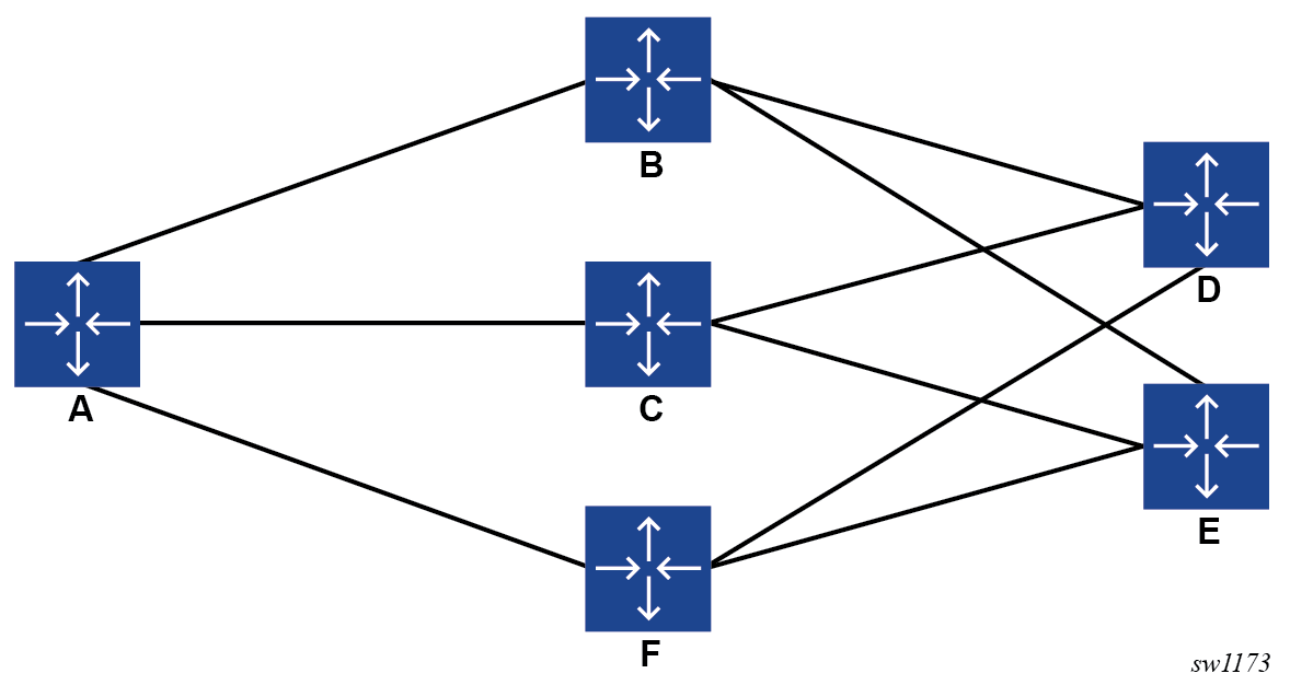
For example, in Topology example 1, from the point of view of A, both D and E are reachable through C. C is the next-hop for both D and E and can have a single protection next-hop, either B or F. If B is chosen as the protection next hop, for an LFA, the packet is forwarded to B for both D and E. B is not on the Shortest Path First (SPF) path to E and not the correct LFA, so an LFA for F is not possible in this network topology.
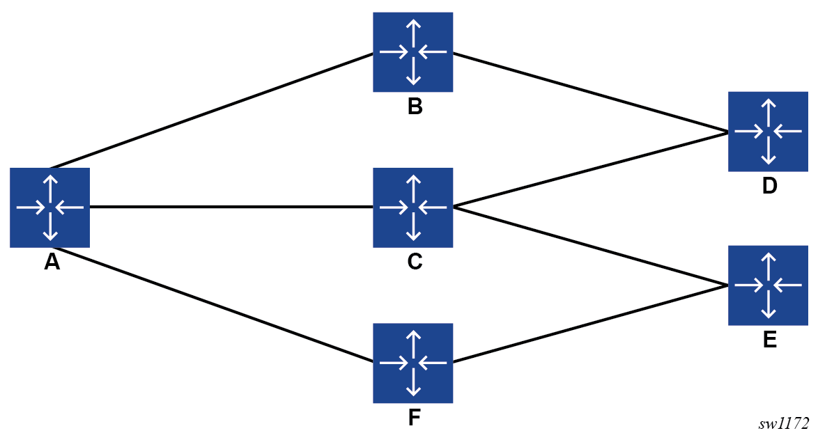
If the network topology is changed as shown in Topology example 2, B can protect both D and E.
BIER FRR with ECMP
When ECMP is enabled for two directly connected BIER routers, multiple next-hops are provided to BIER. BIER uses the next-hop with the smallest IP address for the primary path; all other next-hops can be used as protection paths. BIER uses as a protection next-hop for FRR all ECMP next-hops other than the primary ECMP next-hop. BIER does not hash the BIER packets over multiple ECMP next-hops.
BIER does not hash the BIER packets over multiple ECMP next-hops.
BIER BFD for next-hop failure detection
IGP Bi-directional Forwarding Detection (BFD) must be enabled on BIER neighbors that require FRR support. To register BIER with BFD, BFD must be enabled under BIER.
BIER layers
A multicast BIER network can be divided into three layers:
routing underlay (IGP) has the following capabilities:
establishes BIER adjacencies based on BIER configuration
populates BIER routing table (best path reachability)
provides routing-underlay-based redundancy and convergence, ECMP
BIER layer (BIER routing table, BIER header) has the following capabilities:
advertises and configures the BFR prefix and BIER ID (bitmask bit) for BIER routers
imposes a new BIER header (bitmask: "OR" for receiver PEs based on their BIER IDs as dictated by multicast flow overlay)
forwards multicast traffic using the BIER header and BIER routing table
prevents loops and duplication by using bitmask manipulation and removing the bits for PEs that are not reachable using the L3 interface next hop
Multicast flow overlay (MVPN, BGP) uses MP-BGP to distribute and discover the endpoints (RFC-6513 and RFC-6514).
Implementation
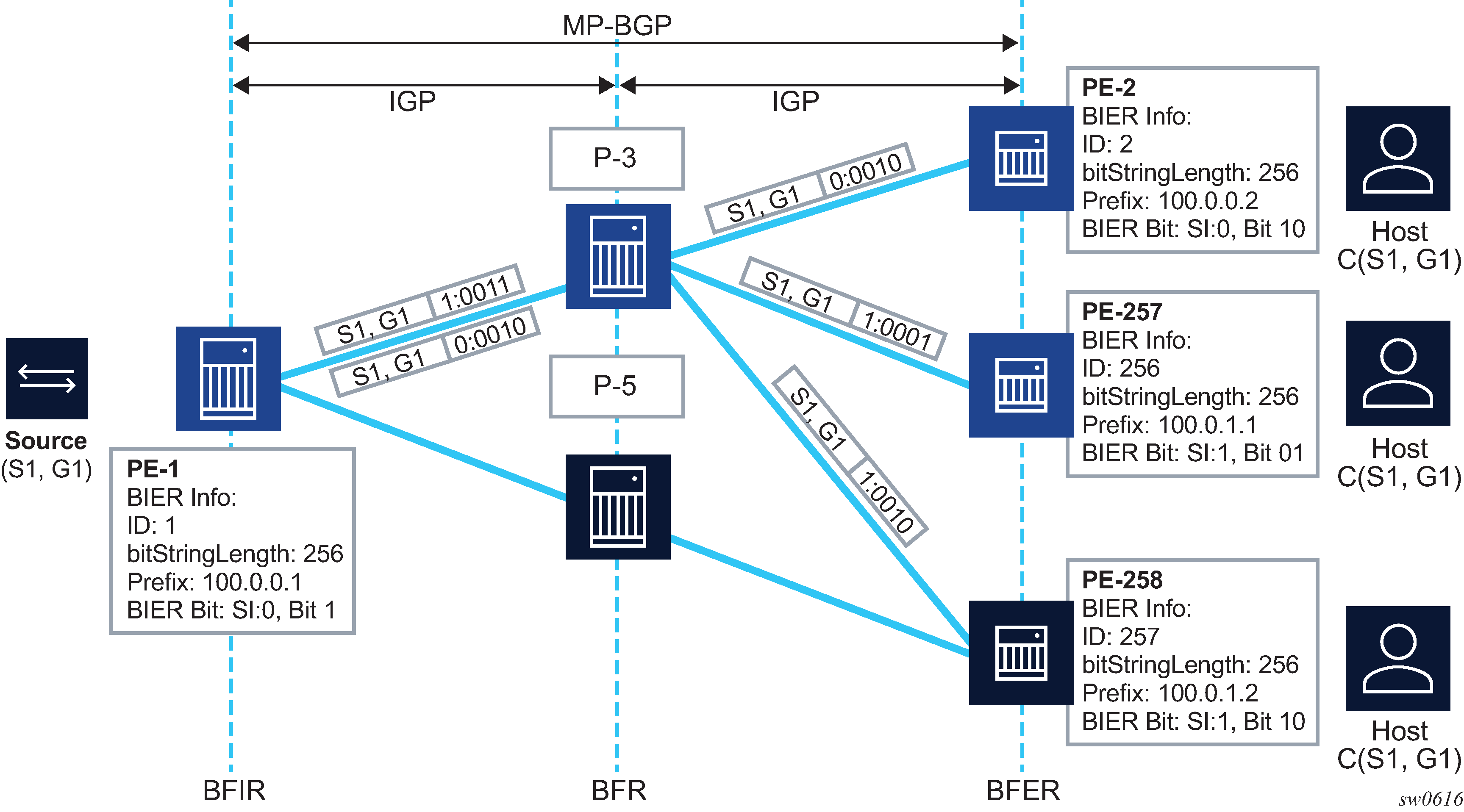
BIER high-level IGP and overlay shows multicast with BIER deployed. IGP is used as the routing underlay, and MP-BGP for NG-MVPN is used as the multicast flow overlay. The BFIR is the source PE-1, BFERs 2, 256, and 257 are receiver PEs, and the remaining routers are BFRs. All routers have their BIER prefix assigned and, additionally, the BFERs have BIER BFR-IDs assigned.
A BFR prefix is a unicast routable IP address (either IPv4 or IPv6) that is either a system loopback or a loopback interface. BFR prefixes are unique within a BIER domain.
A BFR ID is a unique number assigned to BFERs and BFIRs that is used to build the BIER bitmask used to forward packets. BIER IDs should be allocated as a continuous set of IDs starting at 1 to ensure a minimum number of sets are required to achieve multicast BIER connectivity. Sets allow scaling of BIER beyond the bitmask length supported; however, sets require a separate copy of the multicast packet to be forwarded on the same link which may result in unwanted replication.
BIER Sub-domains
Each BIER domain can be divided into sub-domains. A BIER domain supports sub-domains numbered from 0 to 255. Each BIER domain must contain at least one sub-domain, and sub-domain 0 is the default. If a BIER domain contains more than one sub-domain, each BFR in the domain must be provisioned with the set of sub-domains to which it belongs.
A BIER domain is an IGP area, and sub-domains are the different topologies within that area. In IS-IS and OSPF, each topology must also have its own sub-domain ID. For example, in IS-IS a sub-domain is an IS-IS multi-topology. SR OS supports two sub-domains in IS-IS: IPv4-multicast and IPv4-unicast MTs. A sub-domain creates the least traffic engineering in a BIER domain. A user can use separate L3 interfaces into IPv4-unicast MT and a set of disjointed interfaces into the IPv4-multicast MT. This creates separation and traffic engineering for different multicast streams.
For each sub-domain to which a specific BFR belongs, if the BFR is capable of acting as a BFIR or a BFER, it must be provisioned with a BFR ID that is unique within the sub-domain. If a given BFR belongs to more than one sub-domain, it may have a different BFR ID for each sub-domain but this is not required.
BIER set IDs
To increase scalability of BIT String Length (BSL), routers can be grouped into BIER sets.
The BSL dictates how many BFRs can be represented in a BIER set. Each BIER set can contain as many routers as the length of BSL, and it is represented by a BIER Set ID (SI). The Set ID is part of the packet and represented as <SI:Bit Position>. BIER set shows an example set with a BSL of 4.
The BFR ID is programmed into <SI, Bit Position> based on the network BSL.
SI = (BFR-ID – 1)/BSL
BP = ((BFR-ID – 1) mod BSL)+1
For example: BSL 4 and BFR-ID 6 = <SI=1, BP=2>.
BIER works well in an IP TV deployment where the network is in a spine and leaf deployment. SR OS supports 16 set IDs in this type of deployment where there is no packet duplication at the spine.
The SHO can be connected to as many as 16 VHOs.
Each tree can have 256 LEAFs without packet duplication.
Each leaf can have as many hosts on it as the number of supported IGMP/MLD hosts.
BIER encapsulation
SR OS supports BIER MPLS encapsulation.
BIER MPLS encapsulation
The BIER MPLS labels are downstream-assigned MPLS labels that are unique only to the BFR that advertises them. BIER MPLS labels can be advertised using IGP (IS-IS) extension sub-TLVs or BGP extension sub-TLVs.
Penultimate Hop Popping (PHP) is not supported by BIER-MPLS labels as the labels are used to identify the BIER forwarding table that packets need to be looked up in.
BIER MPLS encapsulation shows the BIER MPLS encapsulation label.
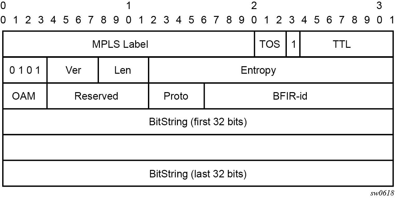
A BIER MPLS label is bound to the forwarding element class. A BIER label is assigned per BIER <SD, <BSL, SI>>. The SR OS supports only a BSL of 256.
Labels are chosen from the first available label in the label pool, and are only allocated locally when IGP advertises the BIER sub-TLVs.
When a packet arrives on a BFR the BIER forwarding table is identified using the MPLS label. BIER forwarding is then completed using the BIER header.
BIER forwarding tables
A BIER forwarding table is built based on the combination of:
Set ID (SI)
BIER String Length (BSL)
Sub Domain (SD)
and saved in the format <SD, BSL, SI>. BIER forwarding tables shows an example of how forwarding tables are built.
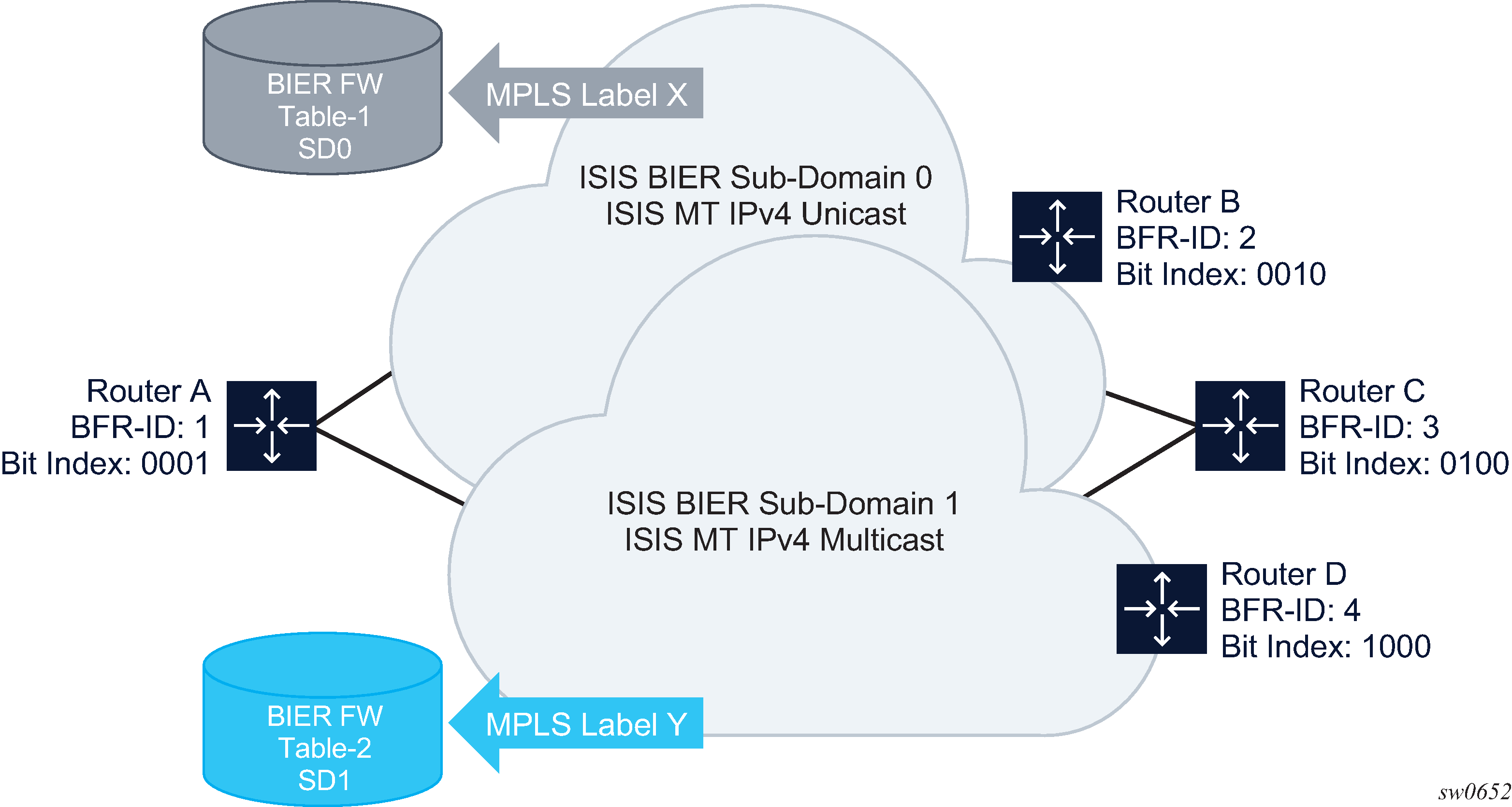
For example, if there are 2 SDs and there are 256 PEs in each SD, there are two forwarding tables, one for each SD. One for <SD=0, BSL=256, SI=0> and the other for <SD=1, BSL=256, SI=0>.
Similarly, if there are 512 PEs in an SD and the BSL is 256, there are two forwarding tables, one for <SD=0, BSL=256, SI=0> and the other for <SD=0, BSL=256, SI=1>.
An MPLS label is assigned locally for each BIER routing table, and advertised.
BIER IS-IS sub-TLVs
BFRs establish BIER adjacencies through IS-IS and exchange their BFR prefixes and BIER IDs as well as transport-related information. IS-IS can be used to exchange the information. BIER IGP sub-TLV shows the IS-IS extensions for BIER and BIER MPLS sub-sub-TLV shows a BIER MPLS sub-sub-TLV.
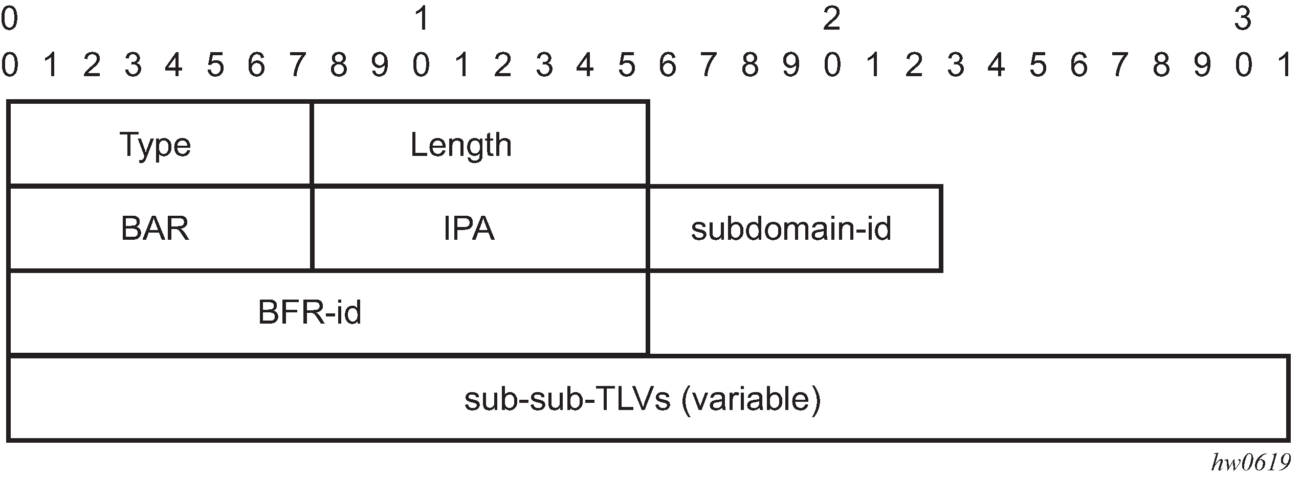

In IS-IS, a new BIER sub-TLV is advertised as part of extended prefix opaque LSA carrying the BFR IP address (loopback) and supported BIER bitmask length for this BFR (multiple TLVs are used to convey support for multiple bitmask lengths). In addition, when MPLS encapsulation is used, a BIER MPLS encapsulation sub-TLV is included that contains the label range used for BIER. The label ranges advertised within the area are unique to a BFR and are used to identify the BIER forwarding context.
Based on the information exchanged, IGP creates a BIER routing table (unicast SPF) to reach each BFER that can be used to route BIER packets. The routing table specifies the shortest unicast path to reach each BFER through (BFERs bitmask, next-hop BFR)-tuples.
BIER sub-TLVs having the wrong length or illegal encoding are ignored and no error is raised. All other sub-TLV or sub-sub-TLV validation is done by the BIER module.
IS-IS BIER support
IS-IS supports multiple levels and BIER is supported under each level using the following rules:
If the ABR is not a BFIR or BFER, the BIER sub-TLV must be leaked between different levels (areas) at the ABR. A BIER template without a BFR ID must be on both levels.
The ABR can support BFIR and BFER functionality. ABR does not support BIER header stitching.
A single area can have level 1 and level 2. In this case, the same template can be programmed on both levels.
IS-IS multi-topologies
IS-IS supports multi-topologies (MT), such as ipv4-unicast, ipv4-multicast, ipv6-unicast, and ipv6-multicast. SR OS supports ipv4-unicast and ipv4-multicast MTs for BIER.
A sub-domain is supported within only one topology. The mapping is indicated by the pair <MT, SD>.
For example, the following combination of <MT, SD>, where MT 0 is IPv4 unicast and MT 3 is IPv4 multicast, are valid:
<MT=0, SD=0>
<MT=0, SD =1>
<MT=0, SD =2>
However, the following combination, where MT 0 is IPv4 unicast and MT 3 is IPv4 multicast, is invalid because an SD belongs to more than one MT:
<MT=0, SD=0>
<MT=3, SD=0>
IPv4-multicast imports routes into the multicast RTM and ipv4-unicast imports routes into the unicast RTM.
A BIER forwarding table (BIFT) is identified using a label. A BIER label is assigned per (<MT, SD>, SI, BSL) and therefore, different MTs point to different BIFTs.
The MT can be used to engineer multicast and BIER routes separately from unicast routes.
BIER intra-AS solution
For intra-AS solutions, ensure that the ABR loopback interface used as the BIER prefix is included in both Level 1 and Level 2, otherwise the BIER prefix is not resolved at the level into which the route was leaked.
Nokia recommends having the loopback interface used as the BIER prefix in Level1/Level2 for intra-AS solutions, which is the default configuration for SR OS.
OSPF BIER support
SR OS supports the BIER TLV for OSPF. Each node uses the TLVs described in RFC 8444 to propagate the BIER information to the entire network. The peer nodes use this information to build their BIER Index forwarding table (BIFT).
OSPF does not support MT. Single BIER sub-domain per area is supported. Inside an area, BIER and virtual links are mutually exclusive.
configure router ospf area bier templateBIER OSPF sub-TLVs
The BFRs establish the BIER adjacencies through OSPF and IS-IS, and exchange their BFR prefixes, BIER IDs, and transport-related information. OSPF can be used for this information exchange. The OSPF extensions for BIER and BIER MPLS sub-TLV are shown below. The peer OSPF routers use this information to build the BIER forwarding table.
The BIER sub-TLV has the following format:
   0                   1                   2                   3
   0 1 2 3 4 5 6 7 8 9 0 1 2 3 4 5 6 7 8 9 0 1 2 3 4 5 6 7 8 9 0 1
   +-+-+-+-+-+-+-+-+-+-+-+-+-+-+-+-+-+-+-+-+-+-+-+-+-+-+-+-+-+-+-+-+
   |              Type             |             Length            |
   +-+-+-+-+-+-+-+-+-+-+-+-+-+-+-+-+-+-+-+-+-+-+-+-+-+-+-+-+-+-+-+-+
   | sub-domain-id |     MT-ID     |              BFR-id           |
   +-+-+-+-+-+-+-+-+-+-+-+-+-+-+-+-+-+-+-+-+-+-+-+-+-+-+-+-+-+-+-+-+
   |    BAR        |    IPA        |            Reserved           |
   +-+-+-+-+-+-+-+-+-+-+-+-+-+-+-+-+-+-+-+-+-+-+-+-+-+-+-+-+-+-+-+-+
   |                      Sub-TLVs (variable)                      |
   +-                                                             -+
Only the following values are supported for the BIER Algorithm (BAR) and, respectively, the IGP Algorithm (IPA): BAR=0 and IPA=0.
The BIER MPLS Encapsulation sub-TLV has the following format:
0                   1                   2                   3
   0 1 2 3 4 5 6 7 8 9 0 1 2 3 4 5 6 7 8 9 0 1 2 3 4 5 6 7 8 9 0 1
   +-+-+-+-+-+-+-+-+-+-+-+-+-+-+-+-+-+-+-+-+-+-+-+-+-+-+-+-+-+-+-+-+
   |              Type             |             Length            |
   +-+-+-+-+-+-+-+-+-+-+-+-+-+-+-+-+-+-+-+-+-+-+-+-+-+-+-+-+-+-+-+-+
   |     Max SI    |                     Label                     |
   +-+-+-+-+-+-+-+-+-+-+-+-+-+-+-+-+-+-+-+-+-+-+-+-+-+-+-+-+-+-+-+-+
   |BS Len |                     Reserved                          |
   +-+-+-+-+-+-+-+-+-+-+-+-+-+-+-+-+-+-+-+-+-+-+-+-+-+-+-+-+-+-+-+-+
BIER forwarding
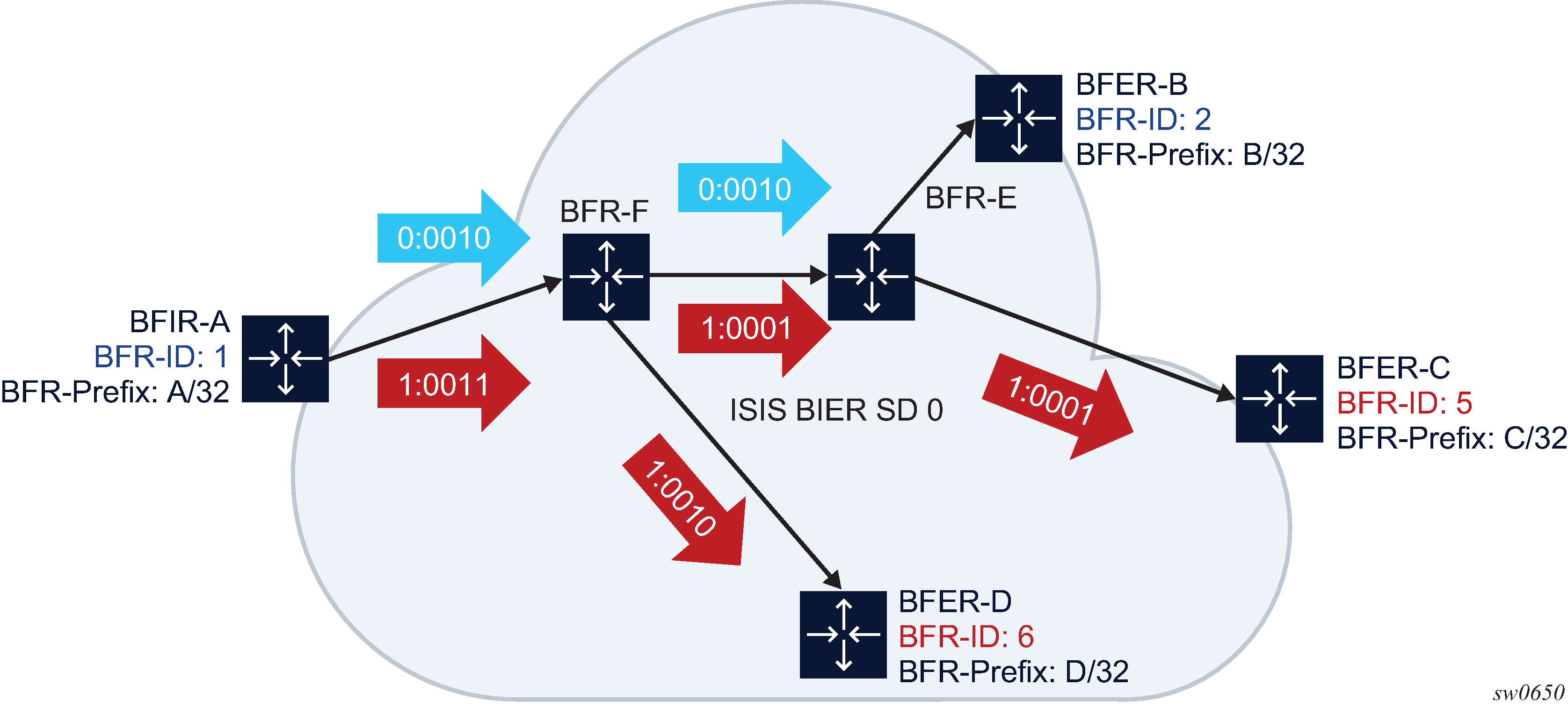
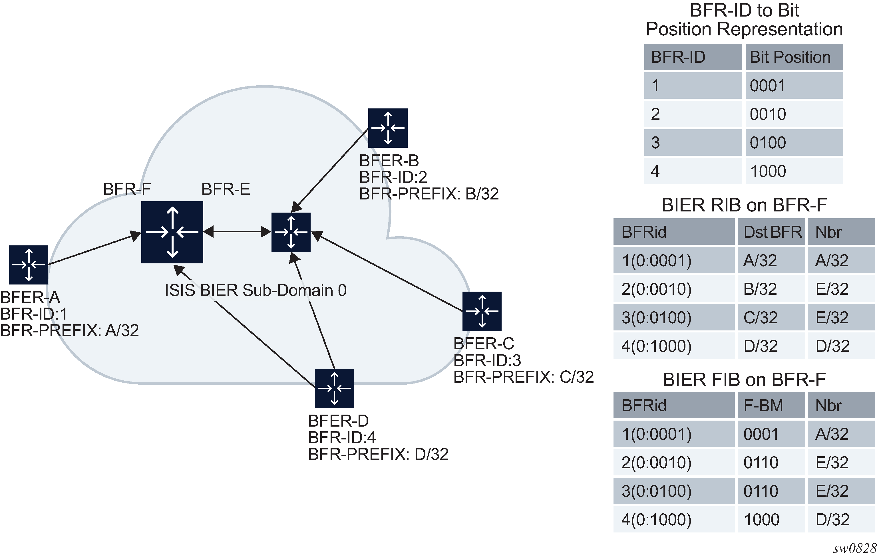
BIER forwarding shows that IGP builds the BIFT using IGP BIER TLVs. Each node also builds its LTN table based on IGP-advertised MPLS labels.
The BIER routing table is constructed based on the combination of:
Set ID (SI)
BIER String Length (BSL)
Sub Domain (SD)
This information is presented as <SD, BSL, SI>. An MPLS label is assigned locally for each BIER routing table and is advertised using IGP to peers.
For example, if there are 512 PEs and the BSL is 256 there are two forwarding tables with each table having its own label as follows:
<SD=0, BSL=256, SI=0> represented with a unique local label
<SD=0, BSL = 256, SI=1> represented with a second unique local label
Each node is presented in the BIER header using its BFR-ID. It is recommended to assign the BFR-IDs sequentially and in a tight order for the PEs so that no bits in the BIER header remain unused.
After all BFRs forward their BIER information using IGP BIER TLV, each BFR builds its own BIER RIB and BIER FIB. In the BIER forwarding example, PE A is represented using BFR-ID 1 (0:0001) and PE B is represented using BFR-ID 2 (0:0010) and so on. Therefore, on BFR F, the routing table is built based on this information. In the BIER forwarding example, BFR A (0:0001) has a destination of A/32 and its neighbor also has a destination of A/32 because of it directly being attached to BFR F. BFR B (0:0010) has destination of B/32 but is reachable using BFR E.
Therefore, the routing table for each PE is built based on its BFR-ID, destination IP address and the direct neighbor which it is attached.
The FIB is built based on the summation of the routes in the RIB that have the same neighbor. In the BIER forwarding example, BFER B and C have the same neighbor/peer BFR E. As a result, their FIB entry is identical BFR-ID 2 (0:0010) Forwarding bit mask 0110 neighbor/peer E/32; where the forwarding bit mask is a summation of BFR-ID nodes B and C (bit 2 and 3).
BIER FIB packet handling
BIER FIB packet handling shows how BIER packets are handled in the FIB.
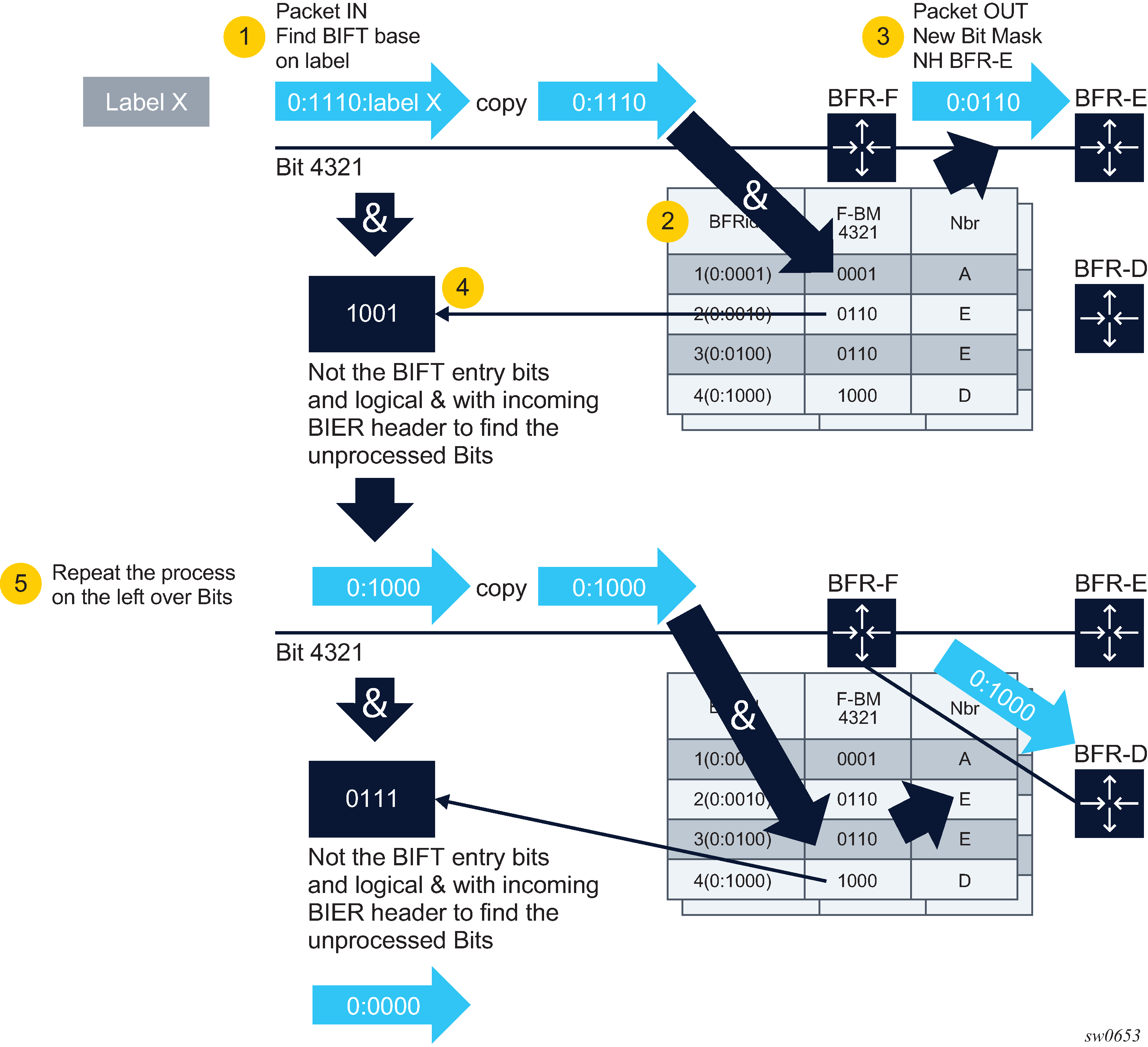
When a BIER packet arrives, the PE checks the label and finds the BIFT for that label and then pops the label.
For the incoming BIER header, it walks the bit index and finds the first entry in the BIFT for that bit position.
Using a logical ‟AND”, the BIER header is combined with the BIFT bit-mask and forwarded to the neighbor. If there are multiple neighbors, the BIFT is programmed with a single entry, the neighbor with the smallest IP address.
Using a logical ‟NOT” on the BIFT bit-mask entry, the PE finds out which bits remain to be processed.
Repeat the process until all the BIER header’s bits are processed.
BIER MVPN
BIER MVPN uses MP-BGP as an overlay to signal MVPN. It uses RFC 6514 the same way P2MP RSVP-TE.
BIER MVPN introduces a new tunnel type of BIER (0x0B).
BIER PMSI replaces PIM, mLDP, and RSVP-TE P2MP in the core. There is no PMSI per (C-S, C-G), PMSI is used to reach all PE nodes interested in the C-Flow.
The VC label represents the VRF. Within the VRF, the payload IP header (C-S,C-G) finds the OIF based on PIM, IGP, and MLD states.
When a root PE (BFIR) receives a multicast packet and determines that the packet needs to be forwarded to the appropriate BFERs, the source PE encapsulates the multicast packet in a BIER header as described in BIER encapsulation. The root PE adds the appropriate VC label advertised by MP-BGP and PTA and forwards it to the BIER domain.
BIER MVPN packet format shows the BIER MVPN packet format.

The original packet has a VC label identifying the VRF added first, then the packet (MPLS payload) is forwarded using BIER PMSI by adding a BIER header identifying the BFERs and BIER label learned using IGP from the next-hop router, as described in BIER forwarding. Finally, when the packet arrives on the BFER, the BIER label is stripped, the BIFT is used to identify whether the packet needs to be handled by a corresponding VRF (because the bit in the header corresponds to the BFER BFR-ID). The BFER strips the BIER header, uses the VC label to identify the VRF instance, strips the VC label, and forwards the packet according to the legacy multicast protocols configured on the SAPs of the MVPN (for example, PIM, IGMP, and MLD OIFs).
SR OS supports BIER as I-PMSI and S-PMSI. By default, all (C-S, C-G) are forwarded using I-PMSI. If a throughput threshold is configured in MVPN and that threshold is surpassed by a (C-S, C-G), then the traffic for that stream is switched from I-PMSI to S-PMSI. BIER uses standard NG-MVPN signaling for S-PMSI and uses leaf AD routes from the leaf PEs to set up S-PMSI to the corresponding leaf that is interested in a specific (C-S, C-G).
The following example shows a BIER MVPN configuration.
MD-CLI
[ex:/configure service vprn "1" mvpn]
A:admin@node-2# info
    c-mcast-signaling bgp
    umh-selection hash-based
    auto-discovery {
        type bgp
    }
    vrf-target {
        unicast true
    }
    provider-tunnel {
        inclusive {
            bier {
                admin-state enable
                sub-domain 0
            }
        }
        selective {
            data-threshold {
                group-prefix 224.0.0.0/4 {
                    threshold 10
                }
            }
            bier {
                admin-state enable
                sub-domain 0
            }
        }
    }
classic CLI
A:node-2>config>service>vprn>mvpn# info
----------------------------------------------
        auto-discovery default
        c-mcast-signaling bgp
        umh-selection hash-based
        provider-tunnel
            inclusive
                bier
                    sub-domain 0
                    no shutdown
                exit
            exit
            selective
                bier
                    sub-domain 0
                    no shutdown
                exit
                data-threshold 224.0.0.0/4 10
            exit
        exit
        vrf-target unicast
        exit
----------------------------------------------
BIER MVPN IPv4 and IPv6
BIER MVPN only generates a single VC label and PMSI for IPv4 or IPv6 traffic belonging to the same VRF.
The BIER header protocol is set to "mpls packet with upstream-assigned label". This label is the VC label identifying the VRF that the packet belongs to. After finding the VRF and removing the VC label, a second lookup on the IP header identifies the packet address family (IPv4 or IPv6). Based on the destination IP, which is the multicast group address, the packet is forwarded out the appropriate MVPN OIF SAPs.
BIER MVPN sub-domain
An MVPN belongs to a single sub-domain (SD). An SD is assigned to the PMSI of the MVPN, and forces the MVPN to resolve the BGP next-hop within that SD. Both I-PMSI and S-PMSI must be configured with the same SD. Different MVPNs can belong to different SDs. For example, mvpn-1 can belong to SD 0 which is an IPv4 unicast MT and mvpn-2 can belong to SD 1 which is an IPv4 multicast MT. This allows different MVPNs to be traffic engineered between different SDs or IS-IS MTs as needed.
BIER templates
A BIER template provides a centralized BIER configuration where the operator can configure all the BIER parameters. The BIER template contains the sub-domain to multi-topology mapping and other BIER configurations, such as the BFR ID and BIER prefix.
Each sub-domain can contain a single IGP Multi-Topology (MT). Currently, SR OS only supports MT for IS-IS but not for OSPF. A BIER template can contain many MTs and SDs. Each SD has its own BIER prefix and BFR ID and can belong to a different MT. The default MT is ipv4-unicast MT.
Use the commands in the following context to create a BIER template.
configure router bier templateAfter you configure a template you can assign it to a corresponding IGP protocol. The IGP protocol chooses the first <SD, MT> that matches its own configured MT. For example, if IS-IS has an MT of IPv4-multicast for the following example BIER template, it uses the sub-domain 1 configuration. It builds its BIER forwarding table base on SD 1 SI, BSL and uses the BIER prefix configured under sub-domain 1 for its IGP sub-TLVs.
MD-CLI
[ex:/configure router "Base" bier template "bier1"]
A:admin@node-2# info
    admin-state enable
    sub-domain 0 {
        bfr-id 4096
        prefix 100.0.0.100
    }
    sub-domain 1 {
        bfr-id 1
        multi-topology ipv4-multicast
        prefix 100.0.0.101
    }
classic CLI
 A:node-2>config>router>bier>template# info
 ----------------------------------------------
        sub-domain 0
            prefix 100.0.0.100
            bfr-id 4096
        exit
        sub-domain 1
            prefix 100.0.0.101
            bfr-id 1
            mt ipv4-multicast
        exit
        no shutdown
    ----------------------------------------------