G.8032 Ethernet ring protection switching
Ethernet ring protection switching offers ITU-T G.8032 specification compliance to achieve resiliency for Ethernet Layer 2 networks. Similar to G.8031 linear protection (also called Automatic Protection Switching (APS)), G.8032 (Ethernet-ring) is built on Ethernet OAM and often referred to as Ring Automatic Protection Switching (R-APS).
Ethernet-rings are supported on VPLS SAPs (VPLS, I-VPLS, B-VPLS). VPLS services supporting Rings SAPs can connect to other rings and Ethernet service using VPLS and R-VPLS SAPs. Ethernet-rings enables rings for core network or access network resiliency. A single point of interconnection to other services is supported. The Ethernet-ring service is a VLAN service providing protection for ring topologies and the ability to interact with other protection mechanisms for overall service protection. This ensures failures detected by Ethernet-ring only result in R-APS switchover when the lower layer cannot recover and that higher layers are isolated from the failure.
Rings are preferred in data networks where the native connectivity is laid out in a ring or there is a requirement for simple resilient LAN services. Because of the symmetry and the simple topology, rings are viewed a good solution for access and core networks where resilient LANs are required. The SR OS implementation can be used for interconnecting access rings and to provide traffic engineered backbone rings.
Ethernet-rings use one VID per control per ring instance and use one (typically) or multiple VIDs for data instances per control instance. A dedicated control VLAN (ERP VLAN) is used to run the protocol on the control VID. G.8032 controls the active state for the data VLANs (ring data instances) associated with a control instance. Multiple control instances allow logically separate rings on the same topology.
The SR OS implementation supports DOT1q, QinQ and PBB encapsulation for data ring instances. The control channel supports dot1q and QinQ encapsulation. Enable the following global command to allow the control channel to support DOT1Q while the data channels use queuing:
- MD-CLI
configure service system extended-default-qinq-sap-lookup - classic
CLI
configure system ethernet new-qinq-untagged-sap
Overview of G.8032 operation
R-APS messages that carry the G.8032 protocol are sent on dedicated protocol VLAN called the Ethernet Ring Protection (ERP) instance. In a revertive case, G.8032 Protocol ensures that one Ring Protection Link (RPL) owner blocks the RPL link. R-APS messages are periodically sent around the ring to inform other nodes in the Ring about the blocked port in the RPL owner node. In non-revertive mode any link may be the RPL. Y.1731 Ethernet OAM CC is the basis of the RAPs messages. Y.1731 CC messages are typically used by nodes in the ring to monitor the health of each link in the ring in both directions. However CC messages are not mandatory. Other link layer mechanisms could be considered – for example Loss Of Signal (LOS) when the nodes are directly connected.
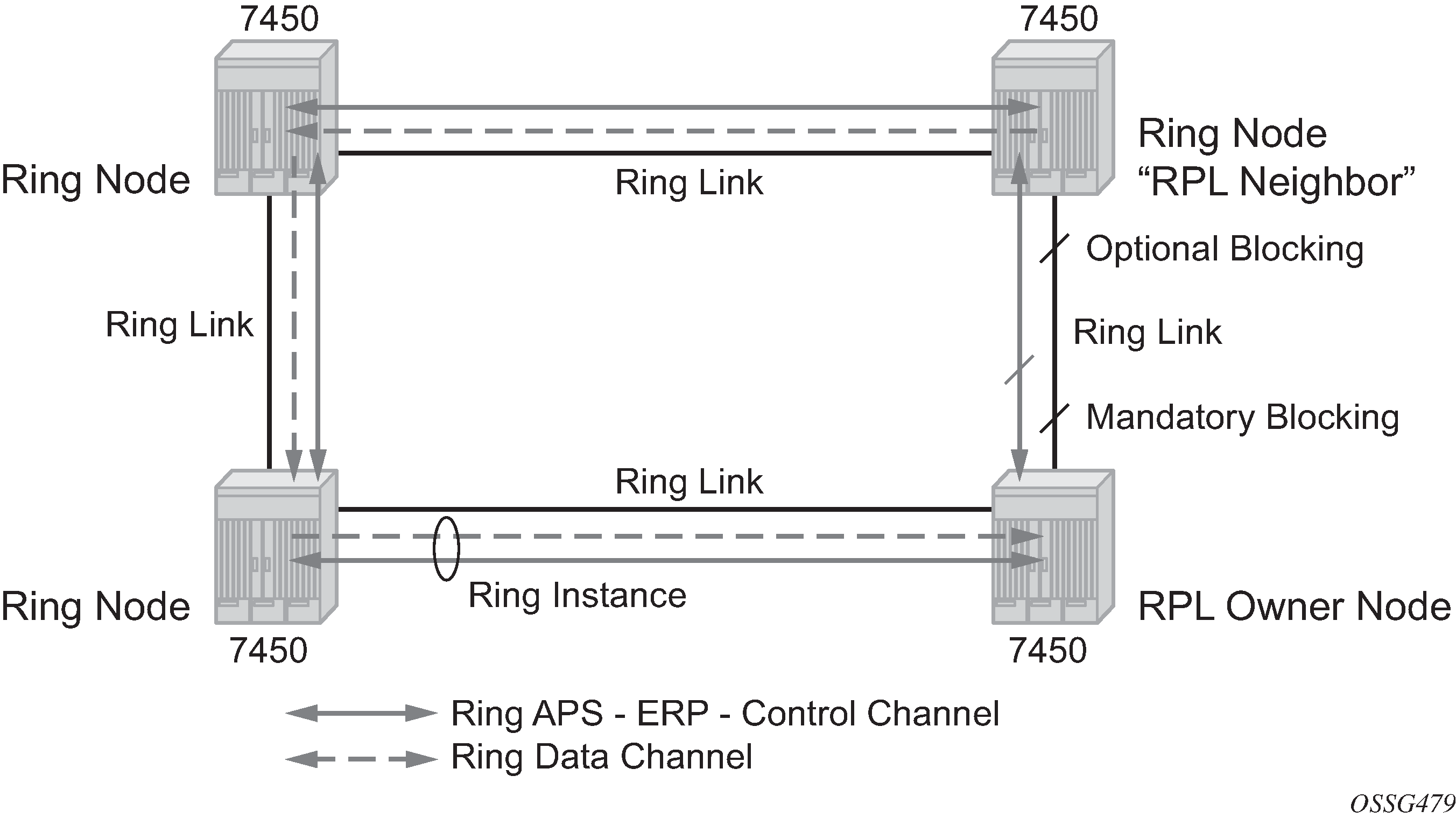
Initially each Ring Node blocks one of its links and notifies other nodes in the ring about the blocked link. When a ring node in the ring learns that another link is blocked, the node unblocks its blocked link possibly causing FDB flush in all links of the ring for the affected service VLANs, controlled by the ring control instance. This procedure results in unblocking all links but the one link and the ring normal (or idle) state is reached. In revertive mode the RPL link is the link that is blocked when all links are operable after the revert time. In non-revertive mode the RPL link is no different than other ring links. Revertive mode offers predictability particularly when there are multiple ring instances and the operator can control which links are blocked on the different instances. Each time there is a topology change that affects reachability, the nodes may flush the FDB and MAC learning takes place for the affected service VLANs, allowing forwarding of packets to continue. 0-1 G.8032 ring in the initial state depicts this operational state:
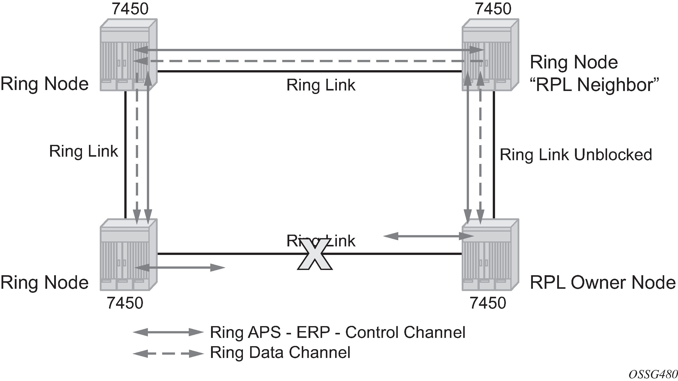
When a ring failure occurs, a node or nodes detecting the failure (enabled by Y.1731 OAM CC monitoring) send R-APS message in both directions. This allows the nodes at both ends of the failed link to block forwarding to the failed link preventing it from becoming active. In revertive mode, the RPL Owner then unblocks the previously blocked RPL and triggers FDB flush for all nodes for the affected service instances. The ring is now in protecting state and full ring connectivity is restored. MAC learning takes place to allow Layer 2 packet forwarding on a ring. 0-1 G.8032 ring in the protecting state depicts the failed link scenario.
When the failed link recovers, the nodes that blocked the link again send the R-APS messages indicating no failure this time. This in turn triggers RPL owner to block the RPL link and indicate the blocked RPL link the ring in R-APS message, which when received by the nodes at the recovered link cause them to unblock that link and restore connectivity (again all nodes in the ring perform FDB flush and MAC learning takes place). The ring is back in the normal (or idle) state.
Within each path, Y.1731 Maintenance Entity Group (MEG) Endpoints (MEPs) are used to exchange R-APS specific information (specifically to co-ordinate switchovers) as well as optionally fast Continuity Check Messages (CCM) providing an inherent fault detection mechanism as part of the protocol. Failure detection of a ring path by one of the mechanisms triggers to activate the protection links. Upon failure, reconvergence times are a dependent on the failure detection mechanisms. In the case of Y.1731, the CCM transmit interval determines the response time. The router supports message timers as low as 10 milliseconds (also 100 ms) so the restoration times are comparable to SONET/SDH. Alternatively, 802.3ah (Ethernet in the First Mile) or simple Loss of Signal can act as a trigger for a protection switch where appropriate. In case of direct connectivity between the nodes, there is no need to use Ethernet CC messaging for liveliness detection.
Revertive and non-revertive behaviors are supported. The Ring protection link (RPL) is configured and Ethernet-rings can be configured to revert to the RPL upon recovery.
G.8032 supports multiple data channels (VIDs) or instances per ring control instance (R-APS tag). G.8032 also supports multiple control instances such that each instance can support RPLs on different links providing for a load balancing capability. However, after services have been assigned to one instance the rest of the services that need to be interconnected to those services must be on the same instance. In other words each data instance is a separate data VLAN on the same physical topology. When there is any one link failure or any one node failure in the ring, G.8032 protocols are capable of restoring traffic between all remaining nodes in these data instances.
Ethernet R-APS can be configured on any port configured for access mode using dot1q, q-in-q encapsulation enabling support for Ethernet R-APS protected services on the service edge toward the customer site, or within the Ethernet backbone. ELINE services (using PBB Epipes with the B-VPLS configured with Ethernet rings), E-LAN services, and E-Tree data services can be afforded Ethernet R-APS protection and, although the Ethernet ring providing the protection uses a ring for protection the services are configured independent of the Ring properties. The intention of this is to cause minimum disruption to the service during Ethernet R-APS failure detection and recovery.
In the implementation, the Ethernet Ring is built from a VPLS service on each node with VPLS SAPs that provides Ring path with SAPs. As a result, most of the VPLS SAP features are available on Ethernet rings if needed. This results in a fairly feature rich ring service.
The control tag defined under each Ethernet-ring is used for encapsulating and forwarding the CCMs and the G.8032 messages used for the protection function. If a failure of a link or node affects an active Ethernet ring segment, the services fail to receive the CCMs exchanged on that segment or receive a fault indication from the Link Layer OAM module. CCMs are optional but MEPs are always configured to provide G.8032 control. Note that the forwarding of CCMs and G.8032 R-APS messages continues in the control VPLS even if the service or its SAPs are administratively shut down. The Ethernet ring instance can be shut down if it is needed to stop the operation of the ring on a node.
For fault detection using CCMs three CC messages plus a configurable hold-off timer must be missed for a fault to be declared on the associated path. The latter mechanism is required to accommodate the existence of additional, 50 ms resiliency mechanism in the optical layer. After it receives the fault indication, the protection module declares the associated ring link down and the G.8032 state machine sends the appropriate messages to open the RPL and flush the learned addresses.
Flushing is triggered by the G.8032 state machine and the router implementation allows flooding of traffic during the flushing interval to expedite traffic recovery.
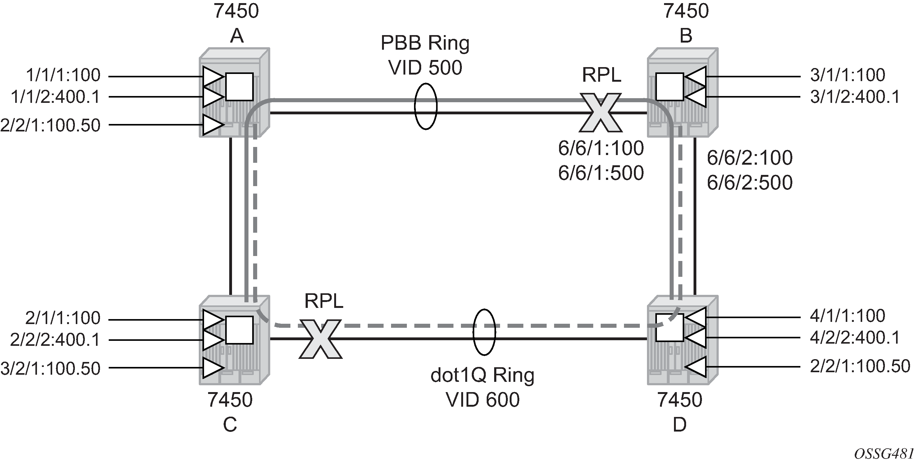
0-3 ring example illustrates a resilient Ring Service. In the example a PBB ring (solid line) using VID 500 carries 2 service VLANs on I-SID 1000 and 1001 for Service VIDs (Dot1q 100 and QinQ 400.1 respectively.) The RPL for the PBB ring is between A and B where B is the RPL owner. Also illustrated is a QinQ service on the (dotted line) ring that uses Dot1q VID 600 for the ring to connect service VLAN 100.50. The two rings have RPLs on different nodes which allow a form of load balancing. The example serves to illustrate that service encapsulations and ring encapsulation can be mixed in various combinations. Also note that neither of the rings is closed loop. A ring can restore connectivity when any one node or link fails to all remaining nodes within the 50 ms transfer time (signaling time after detection).
Ethernet ring configuration (MD-CLI)
[ex:/configure eth-ring 1]
A:admin@node-B# info
    admin-state enable
    description "Ring PBB BLUE on Node B"
    guard-time 5
    revert-time 100
    rpl-node owner
    ccm-hold-time {
        down 100
        up 200
    }
    path "a" {
        # comment: allows protect switching
        # comment: in absence of "tools perform eth-ring force"
        admin-state enable
        description "To A ring link"
        port-and-raps-tag 6/6/1:100
        rpl-end true
        eth-cfm {
            mep
                description "Control MEP"
                ma-admin-name "association-1"
                md-admin-name "domain-1"
                mep-id 1
        }
    }
    path "b" {
        admin-state enable
        description "To D ring link"
        port-and-raps-tag 6/6/2
        rpl-end true
        eth-cfm {
            mep
                ma-admin-name "association-1"
                md-admin-name "domain-1"
                mep-id 1
        }
    }
Ethernet ring configuration (classic CLI)
A:node-2>config>eth-ring# info
----------------------------------------------
    description  "Ring PBB BLUE on Node B"
    revert-time 100
    guard-time 5
    ccm-hold-time down 100 up 200
    rpl-node owner
    path a  6/6/1 raps-tag 100 // CC Tag 100
        description "To A ring link"
        rpl-end
        eth-cfm
            mep 1 domain 1 association 1
                  // Control MEP
            no shutdown
            exit
        exit
        no shutdown // allows protect switching
                      // in absence of "tools perform eth-ring force"
    exit
    path b  6/6/2 raps-tag 100
    description "to D ring link"
        eth-cfm
            mep 1 domain 1 association 1
            no shutdown
            exit
        exit
        no shutdown
    no shutdown
    exit
Ethernet ring used in VPLS service configuration (MD-CLI)
[ex:/configure service]
A:admin@node-2# info
    vpls "10" {
        admin-state enable
        description "Ring Control VID 100 APS SAPS"
        customer "1"
        sap 6/6/1:100 {
            eth-ring 1
            description "TAG for the Control Path a"
        }
        sap 6/6/2:100 {
            eth-ring 1
            description "TAG for the Control Path b"
        }
    }
    vpls "40" {
        admin-state enable
        description "Ethernet Ring 1 VID 500"
        customer "1"
        pbb-type b-vpls
        sap 6/6/1:500 {
            eth-ring 1
            description "TAG for the Data Channel Path a"
        }
        sap 6/6/2:500 {
            eth-ring 1
            description "TAG for the Data Channel Path b"
        }
    }
    vpls "1000" {
        admin-state enable
        description "CPE traffic"
        pbb-type i-vpls
        pbb {
            backbone-vpls "40" {
                isid 1000
            }
        sap 3/1/1:100 {
            description "CPE SAP"
        }
    }
    vpls "1001" {
        admin-state enable
        description "CPE traffic"
        pbb-type i-vpls
        pbb {
            backbone-vpls "40" {
                isid 1001
            }
        sap 3/1/2:400.1 {
            description "CPE SAP"
        }
    }
Ethernet ring used in VPLS service configuration (classic CLI)
A:node-2>config>service# info
----------------------------------------------
        ....
        vpls 10 customer 1 create
            no shutdown
            description "Ring Control VID 100 APS SAPS"
            sap 6/6/1:100 eth-ring 1 create
                             // TAG for the Control Path a
            exit
            sap 6/6/2:100 eth-ring 1 create
                             // TAG for the Control Path b
            exit
        exit
        vpls 40 customer 1 b-vpls create //Data Channel on Ring
            no shutdown
            description "Ethernet Ring 1 VID 500"
            sap 6/6/1:500 eth-ring 1 create
                              // TAG for the Data Channel Path a
            exit
            sap 6/6/2:500 eth-ring 1 create
                              // TAG for the Data Channel Path b
            exit
        exit
        vpls 1000 i-vpls // CPE traffic
            no shutdown
            sap 3/1/1:100 create // CPE SAP
            pbb
                backbone-vpls 40 isid 1000
            exit
        exit
        vpls 1001 i-vpls // CPE traffic
            no shutdown
            sap 3/1/2:400.1 create   // CPE SAP
            pbb
                backbone-vpls 40 isid 1001
            exit
        exit
        ....
Ethernet ring sub-rings
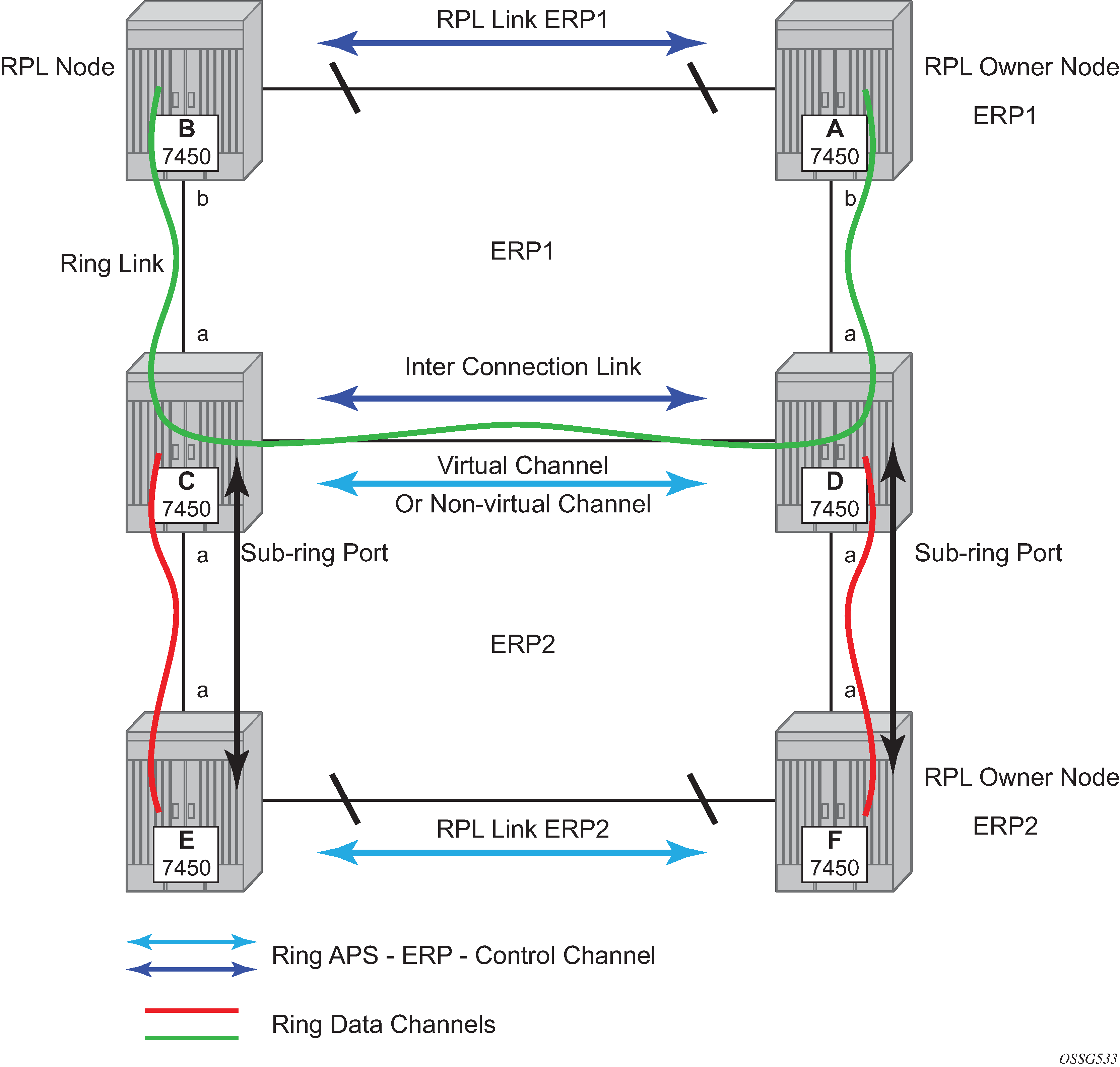
Ethernet Sub-Rings offer a dual redundant way to interconnect rings. The router supports Sub-Rings connected to major rings and a sub-ring connected to a VPLS (LDP based) for access rings support in VPLS networks. 0-4 G.8032 sub-ring illustrates a Major Ring and Sub-Ring scenario. In this scenario, any link can fail in either ring (ERP1 or ERP2) and each ring is protected. Furthermore, the sub ring (ERP2) relies on the major Ring (ERP1) as part of its protection for the traffic from C and D. The nodes C and D are configured as inter connection nodes.
Sub-Rings and Major Rings run similar state machines for the ring logic, however there are some differences. When Sub-Rings protect a link, the flush messages are propagated to the major ring. (A special configuration allows control of this option on the router.) When major rings change topology, the flush is propagated around the major ring and does not continue to any sub-rings. The reason for this is that Major Rings are completely connected but Sub-Rings are dependent on another ring or network for full connectivity. The topology changes need to be propagated to the other ring or network usually. Sub-Rings offer the same capabilities as major rings in terms of control and data so that all link resource may be used.
Virtual and non-virtual channel
The 7450 ESS, 7750 SR, and 7950 XRS support both the virtual channel and non-virtual channel for sub-ring control communication. In the virtual channel mode, a dedicated VID, other than the major ring RAPs control channel is configured as a data instance on the major ring. This allows the sub-ring control messages and state machine logic to behave similar to a major ring. In the non-virtual channel mode, the sub-ring is only connected by the RAPs control channels on the sub-ring itself. This mode offers slightly less redundancy in the RAPs messaging than the virtual channel mode because sub-ring RAPs messages are not propagated across the major ring. When non-virtual link is configured, the protocol allows RPL messages over the sub-ring blocked link.
Sub-ring configuration is similar to major ring configuration and consists of three parts: Ethernet-ring instance configuration, control VPLS configuration, and data VPLS configuration (data instance or data channel). The Ethernet-ring configuration of a sub-ring is tied to a major ring and only one path is allowed.
As with a major ring, the forwarding of CCMs and G.8032 R-APS messages continues in the control VPLS even if the service or its SAPs are administratively shut down. The Ethernet ring instance can be shut down if it is needed to stop the operation of the ring on a node.
The data VPLS can be configured on the major ring, and in the example, shares the same VID (SAP encapsulation) on both the major ring and the sub-ring to keep data on the same VLAN ID everywhere.
The following example shows a sub-ring configuration.
Sub-ring configuration using a virtual link (MD-CLI)
[ex:/configure eth-ring 2]
A:admin@node-2# info
    admin-state enable
    description "Ethernet Sub Ring on Ring 1"
    sub-ring {
        description "Using a virtual link"
        type virtual-link
        interconnect {
            ring-id 1
            propagate-topology-change true
        }
    }
    path "a" {
        admin-state enable
        description "Ring control uses VID 100"
        port-and-raps-tag 1/1/3:100
        eth-cfm {
            mep
                admin-state enable
                ccm true
                control-mep
                ma-admin-name "4"
                md-admin-name "1"
                mep-id 9
            }
        }
Sub-ring configuration using a virtual link (classic CLI)
A:node-2>config>eth-ring# info
----------------------------------------------
description "Ethernet Sub Ring on Ring 1"
sub-ring virtual-link
interconnect ring-id 1
propagate-topology-change
exit
exit
path a 1/1/3 raps-tag 100 // Ring control uses VID 100
eth-cfm
mep 9 domain 1 association 4
ccm-enable
control-mep
no shutdown
exit
exit
no shutdown
exit
no shutdown
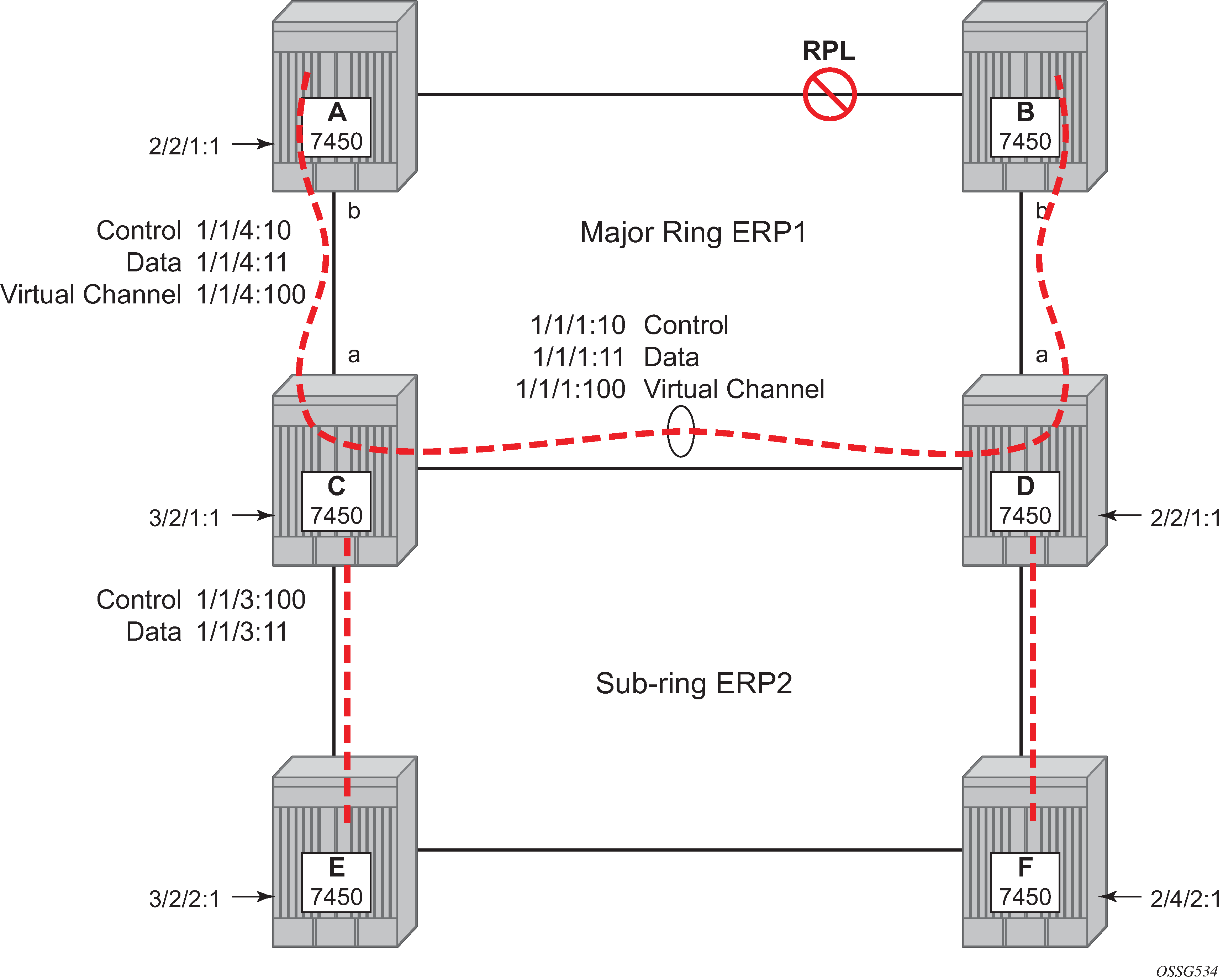
exitIf you configure the sub-ring as a non-virtual link, the previous sub-ring configuration and on all the other sub-ring nodes for the sub-ring are as shown in the following example. The control channel for the major ring ERP1 illustrates that the major ring control is separate from the sub-ring control.
Sub-ring configuration using a non-virtual link (MD-CLI)
[ex:/configure service]
A:admin@node-2# info
     vpls "10" {
        admin-state enable
        description "stadmin="
        customer "1"
        stp {
            admin-state disable
        }
        sap 1/1/1:10 {
            eth-ring 1
            stp {
                admin-state disable
            }
        }
        sap 1/1/4:10 {
            eth-ring 1
            stp {
                admin-state disable
            }
        }
    }
Sub-ring configuration using a non-virtual link (classic CLI)
A:node-2>config>service# info
----------------------------------------------
  vpls 10 customer 1 create
      description "stadmin="
      stp shutdown
      sap 1/1/1:10 eth-ring 1 create
          stp shutdown
          exit
      sap 1/1/4:10 eth-ring 1 create
          stp shutdown
          exit
      no shutdown
  exit
Data configuration for the non-virtual Sub-Ring (MD-CLI)
[ex:/configure service]
A:admin@node-2# info
     vpls "11" {
        admin-state enable
        description "Data on VID 11 for Ring 1"
        customer "1"
        stp {
            admin-state disable
        }
        sap 1/1/1:11 {
            description "VID 11 used for ring"
            eth-ring 1
            stp {
                admin-state disable
            }
        }
        sap 1/1/4:11 {
            eth-ring 1
            stp {
                admin-state disable
            }
        }
        sap 1/1/3:11 {
            description "Sub-ring data"
            eth-ring 2
            stp {
                admin-state disable
            }
        }
        sap 3/2/1:1 {
            description "Local Data SAP"
            stp {
                admin-state disable
            }
        }
    }
Data configuration for the non-virtual Sub-Ring (classic CLI)
A:node-2>config>service# info
----------------------------------------------
  vpls 11 customer 1 create
      description "Data on VID 11 for Ring 1"
      stp shutdown
      sap 1/1/1:11 eth-ring 1 create // VID 11 used for ring
          stp shutdown
      exit
      sap 1/1/4:11 eth-ring 1 create
          stp shutdown
      exit
      sap 1/1/3:11 eth-ring 2 create // Sub-ring data
          stp shutdown
      exit
      sap 3/2/1:1 create
      description "Local Data SAP"
          stp shutdown
      no shutdown
  exit
You could configure a control channel for the sub-ring using a virtual link. This is a data channel as far as the ring 1 configuration. Other ring 1 nodes also need this VID to be configured.
Control channel for the sub-ring using a virtual link (MD-CLI)
[ex:/configure service]
A:admin@node-2# info
     vpls "100" {
        admin-state enable
        description "Control VID 100 for Ring 2 Interconnection"
        customer "1"
        split-horizon-group "s1"
            description "Ring split horizon group"
        stp {
            admin-state disable
        }
        sap 1/1/1:100 {
            split-horizon-group "s1"
            eth-ring 1
            stp {
                admin-state disable
            }
        }
        sap 1/1/4:100 {
            split-horizon-group "s1"
            eth-ring 1
            stp {
                admin-state disable
            }
        }
        sap 1/1/3:100 {
            eth-ring 2
            stp {
                admin-state disable
            }
        }
    }
Control channel for the sub-ring using a virtual link (classic CLI)
A:node-2>config>service# info
----------------------------------------------
  vpls 100 customer 1 create
      description "Control VID 100 for Ring 2 Interconnection"
      split-horizon-group "s1" create //Ring split horizon Group
      exit
      stp shutdown
      sap 1/1/1:100 split-horizon-group "s1" eth-ring 1 create
          stp shutdown
      exit
      sap 1/1/4:100 split-horizon-group "s1" eth-ring 1 create
          stp shutdown
      exit
      sap 1/1/3:100 eth-ring 2 create
          stp shutdown
      exit
      no shutdown
  exit
If you configure the sub-ring as a non-virtual-link, the previous configuration would be like the following example.
Control channel for the sub-ring using a non-virtual link (MD-CLI)
[ex:/configure service]
A:admin@node-2# info
     vpls "100" {
        admin-state enable
        description "Control VID 100 for Ring 2 Interconnection"
        customer "1"
        sap 1/1/3:100 {
            eth-ring 2
            stp {
                admin-state disable
            }
        }
    }
Control channel for the sub-ring using a non-virtual link (classic CLI)
A:node-2>config>service# info
----------------------------------------------
vpls 100 customer 1 create
description "Control VID 100 for Ring 2 Interconnection"
sap 1/1/3:100 eth-ring 2 create
stp shutdown
exit
no shutdown
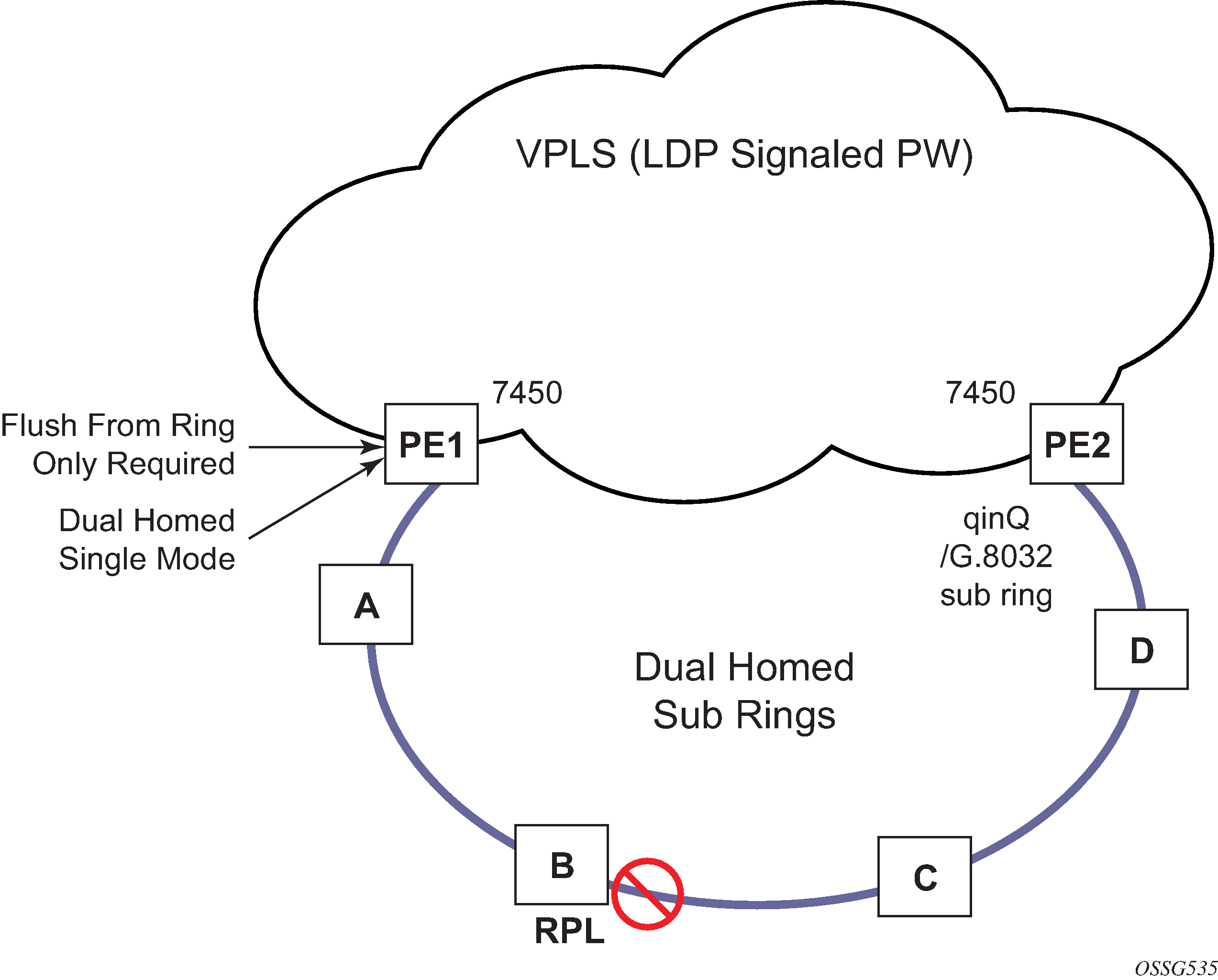
exit The 7450 ESS, 7750 SR, and 7950 XRS allow for a special configuration of the non-virtual link sub-ring that can be homed to a VPLS service illustrated in 0-6 sub-ring homed to VPLS. This is an economical way to have a redundant ring connection to a VPLS service. This is currently supported only for dot1Q and QinQ sub-rings and only on LDP based VPLS. The primary application for this is access rings that require resiliency. This configuration shows the configuration for a sub-ring at an interconnection node without a virtual channel and interconnected to a VPLS. A VPLS service 1 is used to terminate the ring control. The Ethernet ring data SAP appears in the associated LDP based VPLS service 5.
The following example is a sub-ring configuration for VPLS (at PE1 in 0-7 multi ring hierarchy).
Sub-ring configuration for a VPLS (MD-CLI)
[ex:/configure eth-ring 1]
A:admin@node-2# info
    description "Eternet_Ring_1"
    guard-time 20
    revert-time 0
    rpl-node neighbor
    sub-ring {
        interconnect {
            vpls
            propagate-topology-change true
        }
    }
    path "a" {
        admin-state enable
        description "Ethernet Ring : 1 Path on LAG"
        port-and-raps-tag 1/1/3
        eth-cfm {
            mep
                admin-state enable
                ccm true
                control-mep
                ma-admin-name "8"
                md-admin-name "1"
                mep-id 8
        }
    }
Sub-ring configuration for a VPLS (classic CLI)
A:node-2>config>eth-ring# info
----------------------------------------------
      description "Ethernet Ring 1"
      guard-time 20
      no revert-time
      rpl-node nbr
      sub-ring non-virtual-link
          interconnect vpls
              propagate-topology-change
          exit
      exit
      path a 1/1/3 raps-tag 1.1
          description "Ethernet Ring : 1 Path on LAG"
          eth-cfm
          mep 8 domain 1 association 8
               ccm-enable
               control-mep
               no shutdown
            exit
        exit
        no shutdown
    exit
    no shutdown
exit
Configuration for the VPLS ring-control interconnection termination (MD-CLI)
[ex:/configure service]
A:admin@node-2# info
     vpls "1" {
        admin-state enable
        description "Ring 1 control interconnection termination"
        customer "1"
        sap 1/1/3:1.1 {
            description "path a control"
            eth-ring 1
            stp {
                admin-state disable
            }
        }
    }
Configuration for the VPLS ring-control interconnection termination (classic CLI)
A:node-2>config>service# info
----------------------------------------------
  vpls 1 customer 1 create
      description "Ring 1 control interconnection termination"
      stp shutdown
      sap 1/1/3:1.1 eth-ring 1 create //path a control
          stp shutdown
      exit
      no shutdown
  exit
Configuration for the ring data into an LDP-based VPLS (MD-CLI)
[ex:/configure service]
A:admin@node-2# info
     vpls "5" {
        admin-state enable
        description "VPLS Service at PE1"
        customer "1"
        mesh-sdp 5001:5 {
            description "sample LDP MPLS LSPs"
        }
        mesh-sdp 5005:5 {
        }
        mesh-sdp 5006:5 {
        }
        sap 1/1/3:2.2 {
            eth-ring 1
            stp {
                admin-state disable
            }
        sap 1/1/5:1 {
        }
    }
Configuration for the ring data into an LDP-based VPLS (classic CLI)
A:node-2>config>service# info
----------------------------------------------
vpls 5 customer 1 create
description "VPLS Service at PE1"
stp
no shutdown
exit
sap 1/1/3:2.2 eth-ring 1 create
stp shutdown
exit
sap 1/1/5:1 create
exit
mesh-sdp 5001:5 create //sample LDP MPLS LSPs
exit
mesh-sdp 5005:5 create
exit
mesh-sdp 5006:5 create
exit
no shutdown
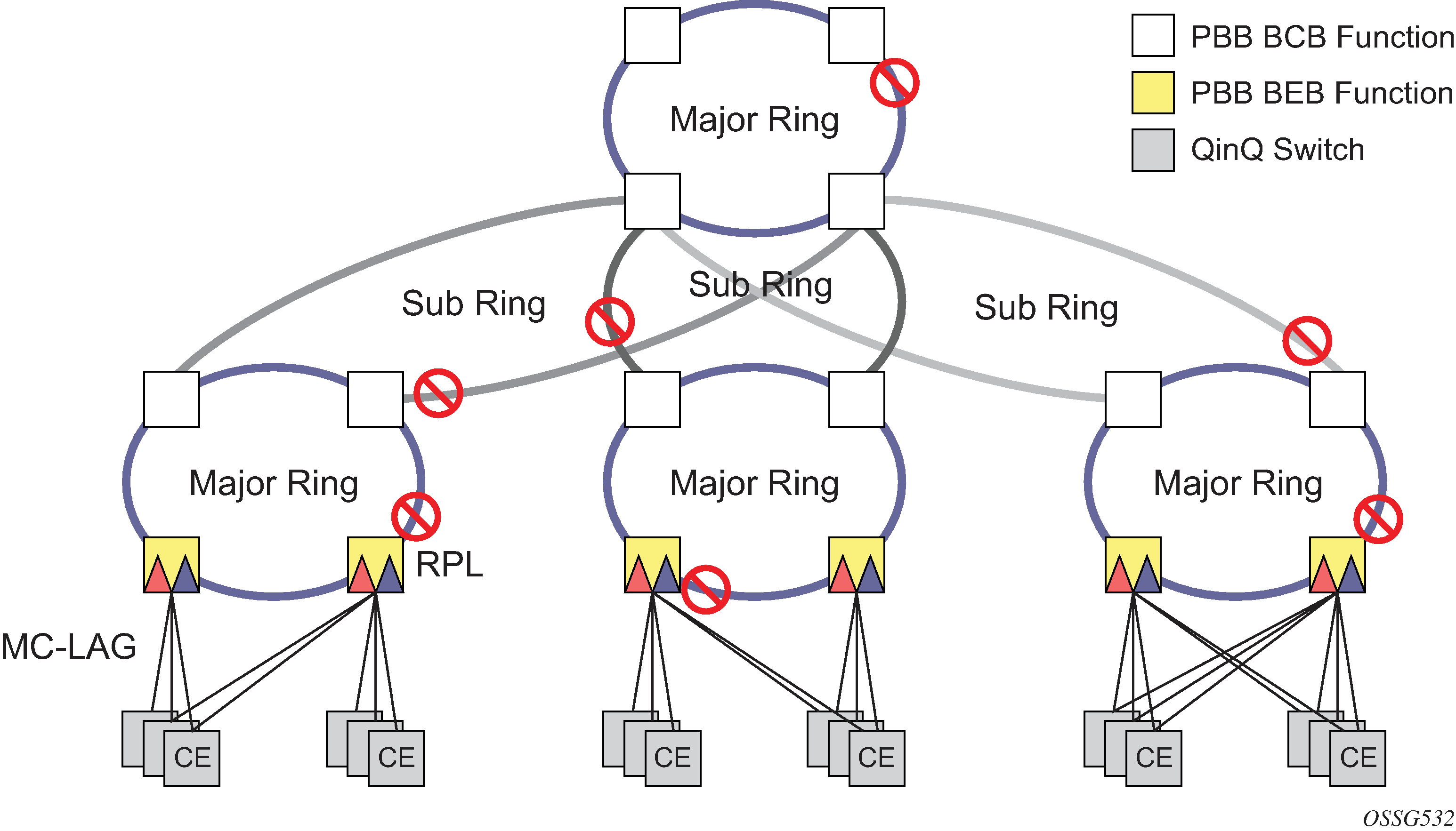
exitEthernet-rings and sub-rings offer a way to build a scalable resilient Ethernet transport network. 0-7 multi ring hierarchy illustrates a hierarchical ring network using PBB where dual homed services are connected to a PBB based Ethernet ring network.
The major rings are connected by sub-rings to the top level major ring. These sub-rings require virtual channel and do not work with non-virtual channel. Ring flushing is contained to major rings, or in the case of a sub-ring link or node failure, to the sub-ring and the directly attached major rings.
LAG support
Ethernet-rings support LAG on Ethernet rings SAPs. However, the use of LAG impact the response time for resiliency. In many cases, the use of multiple ring instances each on a single link may be more suitable from a resiliency and QoS standpoint than using LAG on Ethernet rings in a specific topology. If sub 100ms response is not required, LAG is an option for Ethernet-rings.
OAM considerations
Ethernet CFM is enabled by configuring MEPs on each individual path under an Ethernet ring. Only down MEPs can be configured on each path and optionally, CCM sessions can be enabled to monitor the liveliness of the path using interval of 10 or 100 msec. Different CCM intervals can be supported on the path a and path b in an Ethernet ring. CFM is optional if hardware supports Loss of Signal (LOS) for example, which is controlled by configuring the following command:
- MD-CLI
configure eth-ring path eth-cfm mep ccm false - classic
CLI
configure eth-tunnel path eth-cfm mep no ccm-enable
Up MEPs on service SAPs which multicast into the service and monitor the active path may be used to monitor services.
When Ethernet ring is configured on two ports located on different cards, the SAP queues and virtual schedulers are created with the actual configuration on each card.
Ethernet ring CC messages transmitted over the SAP queues using the default egress QoS policy use NC (network class) as a forwarding class. If user traffic is assigned to the NC forwarding class, it competes for the same bandwidth resources with the Ethernet CCMs. As CCM loss could lead to unnecessary switching of the Ethernet ring, congestion of the queues associated with the NC traffic should be avoided. You must configure different QoS policies to avoid congestion for the CCM forwarding class by controlling the amount of traffic assigned into the corresponding queue.
Details of the Ethernet ring applicability in the services solution can be found in the respective sections of the 7450 ESS, 7750 SR, 7950 XRS, and VSR Layer 2 Services and EVPN Guide.
Support service and solution combinations
The Ethernet rings are supported Layer 2 service, VPLS, I-VPLS, R-VPLS, and B-VPLS instances. The following considerations apply:
Only ports in access mode can be configured as Ethernet-ring paths. The ring ports can be located on the same or different media adapter cards.
-
Dot1q and QinQ ports are supported as Ethernet-ring path members.
-
A mix of regular and multiple Ethernet-ring SAPs and pseudowires can be configured in the same services.