Ethernet connectivity fault management (ETH-CFM)
The IEEE and the ITU-T have cooperated to define the protocols, procedures and managed objects to support service based fault management. Both IEEE 802.1ag standard and the ITU-T Y.1731 recommendation support a common set of tools that allow operators to deploy the necessary administrative constructs, management entities and functionality, Ethernet Connectivity Fault Management (ETH-CFM). The ITU-T has also implemented a set of advanced ETH-CFM and performance management functions and features that build on the proactive and on demand troubleshooting tools.
CFM uses Ethernet frames and is distinguishable by ether-type 0x8902. In specific cases, the different functions use a reserved multicast Layer 2 MAC address that could also be used to identify specific functions at the MAC layer. The multicast MAC addressing is not used for every function or in every case. The Operational Code (OpCode) in the common CFM header is used to identify the PDU type carried in the CFM packet. CFM frames are only processed by IEEE MAC bridges.
IEEE 802.1ag and ITU-T Y.1731 functions that are implemented are available on the SR and ESS platforms.
This section of the guide provides configuration examples for each of the functions. It also provides the various OAM command line options and show commands to operate the network. The individual service guides provide the complete CLI configuration and description of the commands to build the necessary constructs and management points.
ETH-CFM acronym expansions lists and expands the acronyms used in this section.
| Acronym | Expansion | Supported platform |
|---|---|---|
1DM |
One way Delay Measurement (Y.1731) |
All |
AIS |
Alarm Indication Signal |
All |
CCM |
Continuity check message |
All |
CFM |
Connectivity fault management |
All |
CSF |
Client Signal Fail (Receive) |
All |
DMM |
Delay Measurement Message (Y.1731) |
All |
DMR |
Delay Measurement Reply (Y.1731) |
All |
ED |
Ethernet Defect (Y.1731 sub OpCode of MCC) |
All |
LBM |
Loopback message |
All |
LBR |
Loopback reply |
All |
LMM |
(Frame) Loss Measurement Message |
Platform specific |
LMR |
(Frame) Loss Measurement Response |
Platform specific |
LTM |
Linktrace message |
All |
LTR |
Linktrace reply |
All |
MCC |
Maintenance Communication Channel (Y.1731) |
All |
ME |
Maintenance entity |
All |
MA |
Maintenance association |
All |
MD |
Maintenance domain |
All |
MEP |
Maintenance association end point |
All |
MEP-ID |
Maintenance association end point identifier |
All |
MHF |
MIP half function |
All |
MIP |
Maintenance domain intermediate point |
All |
OpCode |
Operational Code |
All |
RDI |
Remote Defect Indication |
All |
TST |
Ethernet Test (Y.1731) |
All |
SLM |
Synthetic Loss Message |
All |
SLR |
Synthetic Loss Reply (Y.1731) |
All |
VSM |
Vendor Specific Message (Y.1731) |
All |
VSR |
Vendor Specific Reply (Y.1731) |
All |
Facility MEPs
Facility MEPs have been introduced to improve scalability, reduce operational overhead, and provide fate sharing without requiring service MEPs. This allows for fault notification for Epipe services that share a common transport. Facility MEPs recognize failure based solely on ETH-CFM detection mechanisms.
There are a total of four facility MEPs, as described below:
- port (physical)
- detects port failure where LoS may be hidden by some intervening network
- LAG (logical)
- validates the connectivity of the LAG entity
- tunnel (logical)
- enables fate sharing of a MEP configured on a QinQ encapsulated access LAG and outer VLAN-ID
- router IP interface (logical)
- validates the Layer 2 connectivity between IP endpoints (troubleshooting only, no CCM functions)
In general, a Facility MEP detects failure conditions using ETH-CFM at the Ethernet Transport layer. The detection is based solely on the MEP entering a fault state as a result of ETH-CC. Conditions outside the scope of ETH-CFM do not directly influence the state of the MEP. However, these outside influences have indirect influence. For example, upon a failure of a port, CCM messages cannot reach the destination. This condition causes the MEP to enter a fault state after the 3.5*interval expires, with the only exception being the acceptance of AIS on a Tunnel MEP. AIS received on all other facilities MEPs are discarded silently when normal level matching targets the local facility MEP.
Facility MEPs are supported as part of a down MEP only. Facility MEPs validate the point to point Ethernet transport between two end points. Facility MEPs do not validate switching functions that are not part of the point to point Ethernet transport. Instead, service MEPs validate switching functions that are not part of the point to point Ethernet transport.
A facility MEP allows for the scaling improvements using fate sharing and leveraging OAM mapping. The OAM mapping functions are part of the fault propagation functions and allow ETH-CFM to move from alarms only to network actions. Service based MEPs are not required to generate AIS in reaction to a facility MEP fault. OAM mapping and generation of fault via fault-propagation means or the AIS function are only available for Epipe services. There is no equivalent AIS generation as part of the facility fault for VPLS, IES, and VPRN. There is no service MEP required to have the SAP transition in the VPLS, IES, and VPRN service context. Normal SAP transition functions does not occur when these services are configured to accept the tunnel fault, or in reaction to a facility fault, where the underlying port or LAG transitions the SAP.
The implementation of facility MEPs must adhere to all platform-specific specifications. For example, sub-second enabled CCM MEPs are supported on port based MEPs. However, any platform restrictions preventing the sub-second enabled MEPs override this capability and require the operator to configure CCM intervals that are supported for that specific platform.
Facility MEPs are created in the same manner as service MEPs, both related to the ETH-CFM domain and association. However, the association used to build the facility MEP does not include a bridge-identifier. The CLI ensures that a bridge ID is not configured when the association is applied to a facility MEP.
Service MEPs and Facility MEPs may communicate with each other, as long as all the matching criteria are met. Because facility MEPs use the standard ETH-CFM packets, there is nothing contained in the packet that would identify an ETH-CFM packet as a facility MEP or Service MEP.
Facility MEPs are not supported on ports that are configured with Eth-Tunnels (G.8031) and only facility MEPs of 1 second and above are supported on the ports that are involved in an Eth-Ring (G.8032).
Common actionable failures
It is important to note that AIS operates independently from the low-priority-defect command option. The low-priority-defect command option affects only the ETH-CFM fault propagation and alarming outside the scope of AIS. By default, a fault in the CCM MEP state machine generates AIS when it is configured. Defect conditions and priority settings illustrates the ETH-CC defect condition groups, configured low-priority-defect setting, priority and defect as it applies to fault propagation. AIS maintains its own low-priority-defect command option which can be used to exclude the CCM defect RDI from triggering the generation of AIS.
| Defect | Low priority defect | Description | Causes | Priority |
|---|---|---|---|---|
|
DefNone |
n/a |
No faults in the association. |
Normal operations. |
n/a |
|
DefRDICCM |
allDef |
Remote Defect Indication. |
Feedback mechanism to inform unidirectional faults exist. It provides the feedback loop to the node with the unidirectional failure conditions. |
1 |
|
DefMACStatus (default) |
macRemErrXcon |
MAC Layer. |
Remote MEP is indicating a remote port or interface not operational. |
2 |
|
DefRemoteCCM |
remErrXon |
No communication from remote peer. |
MEP is not receiving CCM from a configured peer. The timeout of CCM occurs at 3.5x the local CC interval. As per the specification, this value is not configurable. |
3 |
|
DefErrorCCM |
errXcon |
Remote and local configurations do not match the required configuration. |
Caused by different interval timer, domain level issues (lower value arriving at a MEP configured with a higher value), MEP receiving CCM with its MEP-ID. |
4 |
|
DefXconn |
Xcon |
Cross Connected Service. |
The service is receiving CCM packets from a different association. This could indicate that two services have merged or there is a configuration error on one of the SAP or bindings of the service, incorrect association identification. |
5 |
A facility MEP may trigger two distinct actions as a result of fault. Epipe services generate AIS that have been configured to do so as a result of a failure. The level of the AIS is derived from the facility MEP. Multiple client-meg-level can be configured under the facility MEP to allow for operational efficiency in the event a change is required. However, only the lowest AIS level is generated for all the linked and applicable services. VPLS, IES and VPRN SAPs transition the SAP state that are configured to react to the facility MEP state. In addition, Epipe services may also take advantages of OAM and mapping functions.
Before implementing facility MEPs, it is important to understand the behavior of AIS and Fault propagation. Nokia advises considers the following recommendations listed below before enabling or altering the configuration of any facility MEP. These steps must be tested on each individual network before building a maintenance operational procedure (MOP).
-
Do not configure AIS on the facility MEP until the ETH-CCM has been verified. For instance, when a local MEP is configured with AIS before the completion of the remote MEP, the AIS is immediately generated when the MEP enters a fault state for all services linked to that facility MEP.
-
Disable the client MEG level (client-meg-level) command when making changes to existing functional facility MEPs for AIS. Doing this stops the transmit function but maintains the ability to receive and understand AIS conditions from the network.
-
Set the low priority defect (low-priority-defect) command to not report defects DefXcon or lower, to prevent the MEP from entering a defect state, triggering SAP transitions and OAM mapping reactions.
It is important to consider and select what types of fault conditions causes the MEP to enter a faulty state when using fault propagation functions.
The ccm-hold-time supported on port-based MEPs configured with a sub-second interval. The ccm-hold-time prevents the MEP from entering a failed state for 3.5 times the CCM interval plus the additional hold timer.
General detection, processing and reaction
All Facility MEPs that support CCM functions must only have one remote MEP peer. Facilities MEPs validate point-to-point logical or physical Ethernet transports. Configure service MEPs if multipoint-service validation is required.
There are three distinct functions for a Facility MEP:
general detection
This determines that a fault has occurred. In this case, the MEP performs its normal functions such as: recognizing the fault condition, maintaining the local errors and reporting based on low-priority-setting, and taking no further action. This is the default.
fault processing
By default, there is no action taken as a result of a MEP state machine transition beyond alarming. To take action which may include a SAP operational state change, generation of AIS, or fault propagation and mapping, the appropriate facility fault command option must be configured and enabled. The general reaction to a fault is described below. More details are including the section describing the functions of the individual facility MEPs.
port
This affects link operational status of the port. Facility failure changes the operational state to Link Up. This indicates that the port has been brought down as a result of OAM MEP Fault. This operational state has the equivalent function to port down condition.
LAG
This affects link operational status of the LAG. Facility failure changes the operational state of the LAG to DOWN. This indicates that the LAG has be brought down as a result of OAM MEP Fault.
tunnel MEP
Note: The tunnel-fault command option applies for classic CLI.This enters faulty state and further impacts the operational state of the SAPs linked to the tunnel MEP state.
Epipe SAP remains operationally up, SAP's flag set to OamTunnelMEPFault
Ipipe SAP remains operationally up, SAP's flag set to OamTunnelMEPFault
VPLS, IES and VPLS SAPs transition to operationally down, the SAP's flag is set to OamTunnelMEPFault. SAP operational states and flags are affected only by the tunnel-fault command option.
router IP interface
This affects operational status of the IP Interface.
propagation
Services appropriately linked to the Facility MEP take the following service-specific actions:
Epipe generates AIS or use Fault Propagation and OAM mappings.
VPLS does not propagate fault using AIS unless service-based MEPs are configured and contain MEP-specific AIS configuration. SAP transitions occur when the facility MEP failure is recognized by the service.
IES and VPRN, as Layer 3 functions, act as boundaries for Layer 2 fault processing. No propagation functions occur beyond what is currently available as part of fault propagation: SAP down.
Enabling AIS command options
Epipe services support the following command under the SAP hierarchy level:
- MD-CLI
configure service epipe sap eth-cfm ais true - classic
CLI
configure service epipe sap eth-cfm ais-enable
configure service epipe sap eth-cfm mep ais-enable
This structure, outside of the MEP context, creates a special link between the Epipe service SAP and the facility MEP. If a facility MEP enters a fault state, all Epipe service SAPs with this configuration generate lowest-level AIS at the level configured under the facility MEP. As with fault propagation, AIS generation is restricted to Epipe services only. The actions taken by the other services are described in more detail in the relevant facility MEP sections.
Note: Facility MEPs do not support the generation of AIS to an explicitly configured endpoint. An explicitly configured endpoint abstracts multiple endpoints within its context; for example, pseudowire (PW) redundancy. Although the linkage of a facility MEP to an Epipe, and AIS generation triggered as a result of the facility MEP failure can be configured, AIS generation is not supported and is unpredictable. When an explicit endpoint is configured, service-based MEPs are required when AIS generation is the needed behavior.- MD-CLI
Port-based MEP
There is an increase in services that share the same facilities, and that service-based ETH-CFM, although very granular, comes at an operational and scalability cost. Configuring a MEP on a physical port allows ETH-CFM to detect Ethernet transport failures, raise a facility alarm, and perform local fault processing. A facility event is coordinated to the services or functions using the affected port.
The port-based MEP is intended to validate physical connectivity to the peer MEP, and provide on-demand and scheduled troubleshooting, and performance management functions.
Port facility MEPs are advantageous in cases where port-to-port connectivity issues are obscured, similar to the deployment use cases for IEEE 802.3 Clause 57 – Operation, Administration and Maintenance (formerly 802.3ah). Clause 57 specification limits the transmit rate to 10 packets/s, or a send duration of 100 ms. To more quickly detect port failure conditions between two peers, a port-based facility MEP may be configured to use the supported sub-second CCM intervals. One-second and above timers are also available for configuration in cases where aggressive timers are not necessary. All platform-specific requirements must be met for the needed interval. ETH-CFM and IEEE 802.3ah Clause 57 can influence the operational state of the port over which they are configured.
The 802.3ah and ETH-CFM protocols cannot simultaneously control the individual port operational state. Both protocols can be decoupled from the port operational state. The 802.3ah protocol defaults to influencing the port operational state. This can be modified by using the following command. When the following command is configured, the ETH-OAM protocol does not impact the state of the port when there is a failure in the protocol state machine (discovery, configuration, timeout, loops, and so on). There is only a protocol warning message on the port.
- MD-CLI
configure port ethernet efm-oam ignore-efm-state true - classic
CLI
configure port ethernet efm-oam ignore-efm-state
The ETH-CFM protocol ETH-CC defaults to alarm-only without influencing the port operational state. This can be modified by using the following command. When configured, the following command allows the facility MEP to move from just reporting the alarm condition to network actionable function.
- MD-CLI
configure port ethernet eth-cfm mep facility-fault true - classic
CLI
configure port ethernet eth-cfm mep facility-fault
The 802.3ah and ETH-CFM protocol combinations that conflict with the single-port operational control rule are rejected with a configuration error. Port-level ETH-CFM PDUs are sent untagged because they are not specific to any service or VLAN. The ETH-CFM packets generated from a port-based facility MEP must use an ETH-CFM level of 0 or 1. Any ETH-CFM PDU that arrives untagged on a port matching the level for the port-based facility MEP is terminated and processed by the port-based MEP.
Do not use MEPs configured with level 0 to validate logical transport or services. Consider blocking all non-customer (5-7) levels at the entry point of the network.
It is not expected that faults from other parts of the network are propagated and terminated on a port-based facility MEP. This type of facility MEP provides a one-to-one validation with a single remote MEP across on a physical port, allowing locally detected faults to be propagated to the endpoints of the network.
A physical port may only have a single port-based facility MEP. Because the purpose of the MEP is to control the port state, more than one is not required per port.
When a port enters the link up operational state because of ETH-CFM, the MEP continues to transmit and receive to properly clear the condition. However, when the port fails for reasons that are not specific to ETH-CFM, it stops transmit and receive functions until the condition is cleared. This is different than the behavior of a service MEP, because facility MEPs only supports Down MEPs, while some service-based MEPs support UP and Down MEPs. In the case of UP MEPs, a single port failure may not prevent all the CCMs from egressing the node. So the operational method for service-based MEPs remains the same: continuing to increase the counter for CCM transmit in the event of port failure, regardless of the reason. The transmit ETH-CCM counters do not apply to sub-second CCM-enabled MEPs.
There are two types of port in the context of port-based facility MEPs. The first type are ports that are not part of a LAG, referred to as non-member ports. The second type of ports are ports that are part of a LAG, referred to member ports, and have slightly different reactions to fault. MEPs configured directly on either type of port act the same. However, a MEP configured on a non-member port and a MEP configured on a member port handle fault propagation differently.
When a port-based facility MEP causes the port to enter the operational state Link Up, normal processing occurs for all higher level functions. If the port is a member port, unless the entire LAG enters a non-operational state, the SAP configured on the LAG remains operational. A facility MEP on a member port has no direct influence on the SAP. The purpose of a facility MEP on a member port is to provide feedback to the LAG. The LAG performs the normal computations in response to a port down condition. A facility MEP configured on a non-member port does have direct control over the SAPs configured on the port. Therefore, when a port fails, all the SAPs transitions to the operation state down. When this occurs, fault may be propagated using AIS for those Epipe services that are AIS-enabled under the SAP. For the services that have MEPs configured on the SAP or the binding, fault propagation occurs. For VPLS, IES and VPRN services, normal reaction to a SAP entering a down state occurs.
When a LAG is administratively shutdown, the member ports are shutdown automatically. As a result, packet reception is interrupted, causing ETH-CFM functions running on physical member ports to lose connectivity. Therefore, the CFM functions on member ports are somewhat tied to the LAG admin status in this case.
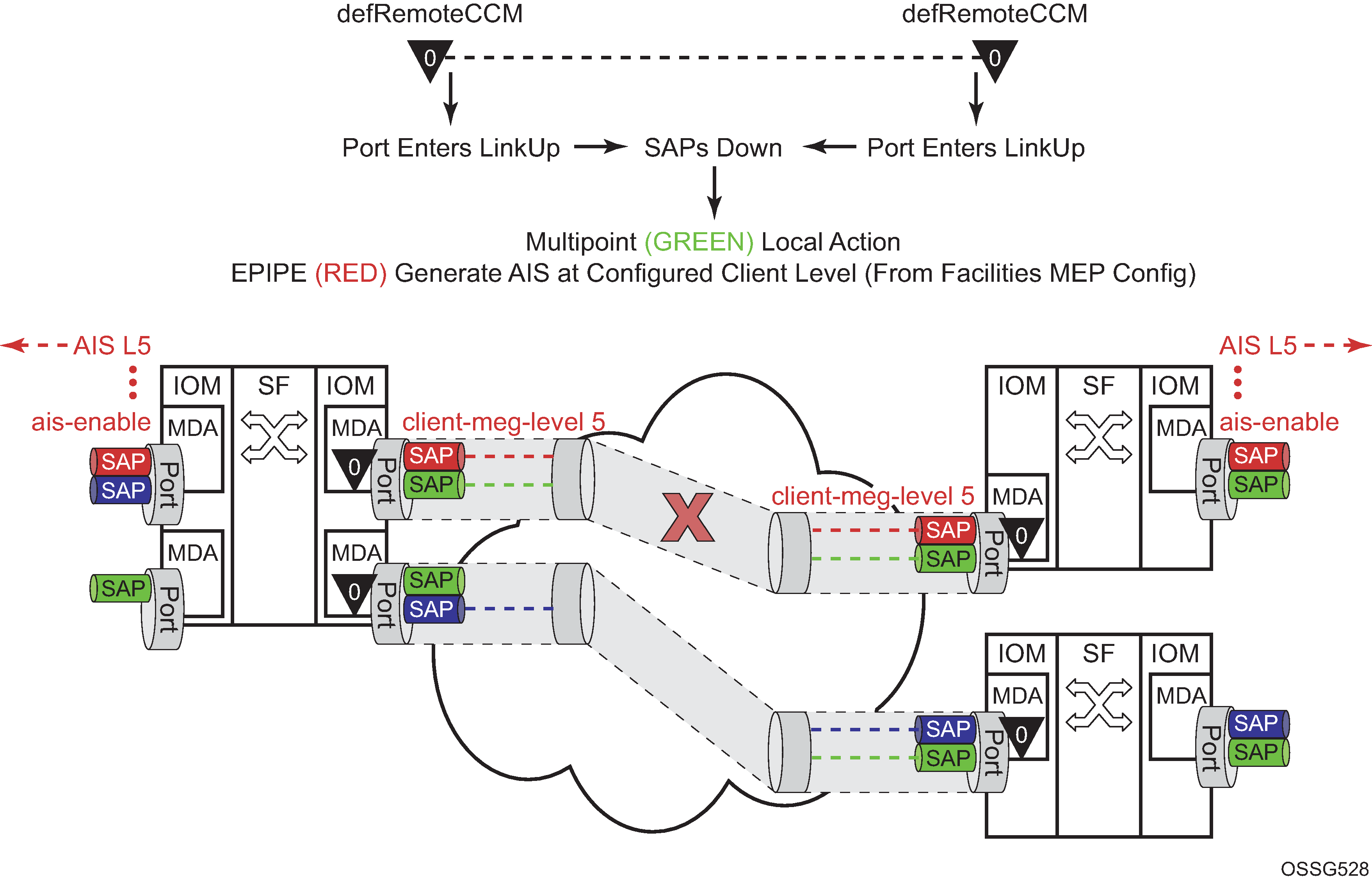
Fault handling non-member port provides an example of how an ETH-CFM failure reacts with the various services that share that port. The green Epipe service generates AIS as a result of the port failure using the client-meg-level command configured on the port facility MEP. The multipoint service takes location configured action when the SAP transitions to the down operational state. The blue Epipe service is not affected by the port link up state as a result of ETH-CFM fault.
A debounce function has been implemented to prevent notifying every port state change if a port bounces multiple times within a window. Up to four notifications are accepted in a three second window. If the third port state is a down state change, the fourth is ignored. If the fourth port state change is a down state change, it is processed. After that, no further state changes are accepted for the duration of the three second timer. This helps ensure that the port is not artificially held in the UP state when it is not operation. Following the processing of that last port state change, the third or fourth, the latest state change is held and processed at the expiration of the three second hold timer.
Port based facility MEPs are not allowed on a port that is configured with G.8031 Ethernet Tunnels.
Port-Based MEP example displays an example of how port-based MEPs and defect conditions translate into service awareness without service-based MEPs. From the two nodes perspective, they are aware they are directly connected at the port. The two nodes are unaware of any of the cross connections that allow this to occur.
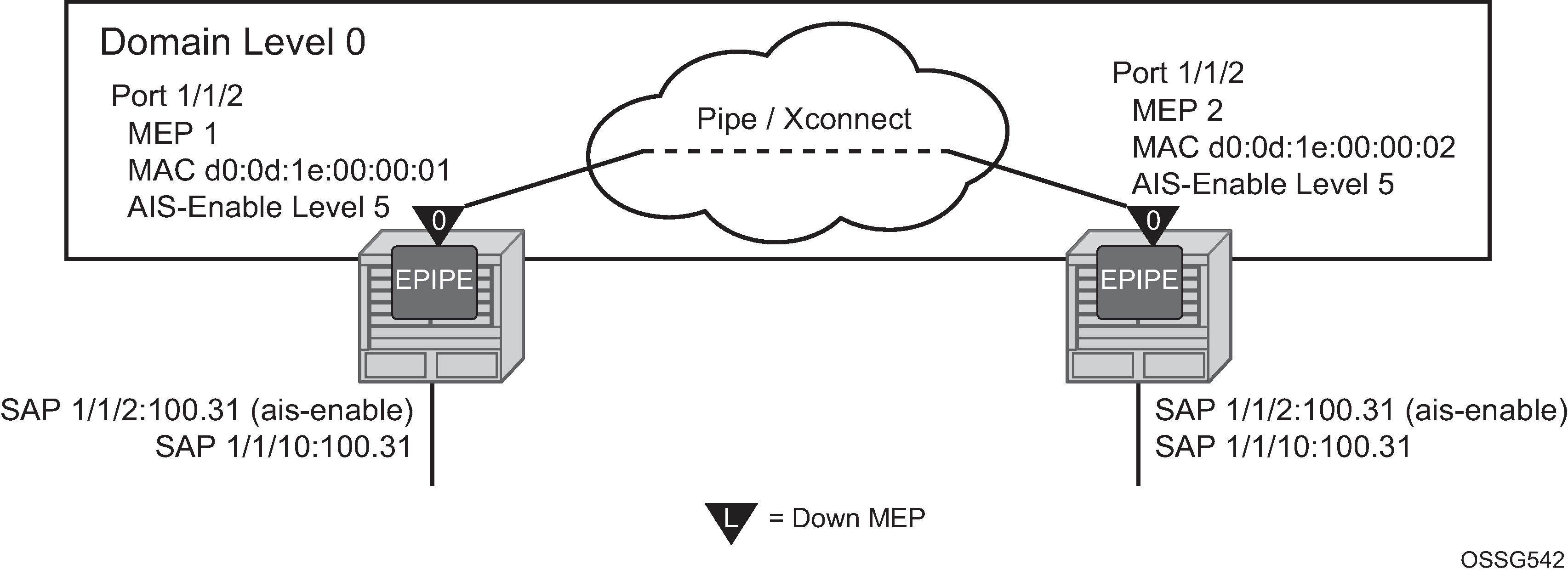
Use the following commands to configure port-based MEPs. When the MEP enters any defect state, an AIS is generated to any Epipe services that have AIS enabled under the sap eth-cfm hierarchy.
- MD-CLI
configure port ethernet eth-cfm mep facility-fault true configure port ethernet eth-cfm mep ais client-meg-level - classic
CLI
configure port ethernet eth-cfm mep facility-fault
configure port ethernet eth-cfm mep ais-enable client-meg-level
Node1 configuration (MD-CLI)
[ex:/configure eth-cfm]
A:admin@node-1# info
    domain "10" {
        level 0
        format none
        association "1" {
            icc-based "FacilityPort0"
            ccm-interval 1s
            remote-mep 2 {
            }
        }
    }

[ex:/configure port 1/1/2]
A:admin@node-1# info
    admin-state enable
    ethernet {
        mode access
        encap-type qinq
        eth-cfm {
            mep md-admin-name "10" ma-admin-name "1" mep-id 1 {
                admin-state enable
                mac-address d0:0d:1e:00:00:01
                ccm true
                facility-fault true
                ais {
                    client-meg-level [5]
                }
            }
        }
    }
[ex:/configure service epipe "7"]
A:admin@node-1# info
    sap 1/1/2:100.31 {
        eth-cfm {
            ais true
        }
    }
    sap 1/1/10:100.31 {
    }
Node1 configuration (classic CLI)
A:node-1>config>eth-cfm# info
----------------------------------------------
        domain 10 format none level 0
            association 1 format icc-based name "FacilityPort0"
                ccm-interval 1
                remote-mepid 2
            exit
        exit
----------------------------------------------

A:node-1>config>port# info
----------------------------------------------
        ethernet
            mode access
            encap-type qinq
            eth-cfm
                mep 1 domain 10 association 1
                    ais-enable
                        client-meg-level 5
                    exit
                    facility-fault
                    ccm-enable
                    mac-address d0:0d:1e:00:00:01
                    no shutdown
                exit
            exit
        exit
        no shutdown
----------------------------------------------

A:node-1>config>service>epipe# info
----------------------------------------------
            sap 1/1/2:100.31 create
                eth-cfm
                    ais-enable
                exit
            exit
            sap 1/1/10:100.31 create
            exit
            no shutdown
----------------------------------------------
Node2 configuration (MD-CLI)
[ex:/configure eth-cfm]
A:admin@node-2# info
    domain "10" {
        level 0
        format none
        association "1" {
            icc-based "FacilityPort0"
            ccm-interval 1s
            remote-mep 1 {
            }
        }
    }
[ex:/configure port 1/1/2]
A:admin@node-2# info
    admin-state enable
    ethernet {
        mode access
        encap-type qinq
        eth-cfm {
            mep md-admin-name "10" ma-admin-name "1" mep-id 2 {
                admin-state enable
                mac-address d0:0d:1e:00:00:02
                ccm true
                facility-fault true
                ais {
                    client-meg-level [5]
                }
            }
        }
    }
[ex:/configure service epipe "7"]
A:admin@node-2# info
    sap 1/1/2:100.31 {
        eth-cfm {
            ais true
        }
    }
    sap 1/1/10:100.31 {
    }
Node2 configuration (classic CLI)
A:node-2>config>eth-cfm# info
----------------------------------------------
        domain 10 format none level 0
            association 1 format icc-based name "FacilityPort0"
                ccm-interval 1
                remote-mepid 1
            exit
        exit
----------------------------------------------

A:node-2>config>port# info
----------------------------------------------
        ethernet
            mode access
            encap-type qinq
            eth-cfm
                mep 2 domain 10 association 1
                    ais-enable
                        client-meg-level 5
                    exit
                    facility-fault
                    ccm-enable
                    mac-address d0:0d:1e:00:00:02
                    no shutdown
                exit
            exit
        exit
        no shutdown
----------------------------------------------

A:node-2>config>service>epipe# info
----------------------------------------------
            sap 1/1/2:100.31 create
                eth-cfm
                    ais-enable
                exit
            exit
            sap 1/1/10:100.31 create
            exit
            no shutdown
----------------------------------------------
There are two different levels of fault to consider: Port State/Operational State driven by the low-priority-defect setting and the generation of AIS driven by the defect state for the MEP.
If the low-priority-defect is left at the default macRemErrXcon setting, then port state may not match on both nodes. If an unidirectional failure is introduced for port-based MEPs, then RDI is received on one of the nodes and the other node would report and react to RemoteCCM (timeout). The RDI defect is below the default low-priority-defect in priority, and the port would remain operationally UP and the port state would remain UP. The MEP that has timed out the peer MEP takes port level action because this defect is higher in priority than the default low-priority-defect. The port state is recorded as Link Up and the Port is operationally down with a Reason Down: ethCfmFault. To avoid this inconsistency, set the low-priority-defect command option to detection unidirectional failures using the allDef option.
The following show commands reveal the condition mentioned above within the network. Node 1 is receiving RDI and Node 2 has timed out its peer MEP.
Node1 outputs
The following outputs display information for the Node1 example configuration.
Use the following command to display port information.
show port===============================================================================
Ports on Slot 1
===============================================================================
Port Admin Link Port Cfg Oper LAG/ Port Port Port C/QS/S/XFP/
Id State State MTU MTU Bndl Mode Encp Type MDIMDX
-------------------------------------------------------------------------------
...
1/1/2 Up Yes Up 1522 1522 - accs qinq xcme
...Use the following command to display information for a specific port.
show port 1/1/2===============================================================================
Ethernet Interface
===============================================================================
Description : 10/100/Gig Ethernet SFP
Interface : 1/1/2 Oper Speed : 1 Gbps
Link-level : Ethernet Config Speed : 1 Gbps
Admin State : up Oper Duplex : full
Oper State : up Config Duplex : full
Physical Link : Yes MTU : 1522
...Use the following command to display the maintenance endpoint, maintenance domain, and maintenance association information.
show eth-cfm mep 1 domain 10 association 1===============================================================================
Eth-Cfm MEP Configuration Information
===============================================================================
Md-index : 10 Direction : Down
Ma-index : 1 Admin : Enabled
MepId : 1 CCM-Enable : Disabled
Port : 1/1/2 VLAN : 0
Description : (Not Specified)
FngState : fngReset ControlMep : False
LowestDefectPri : macRemErrXcon HighestDefect : none
Defect Flags : bDefRDICCM
Mac Address : d0:0d:1e:00:00:01 ControlMep : False
CcmLtmPriority : 7
CcmTx : 1481 CcmSequenceErr : 0
Fault Propagation : disabled FacilityFault : Notify
MA-CcmInterval : 1 MA-CcmHoldTime : 0ms
Eth-1Dm Threshold : 3(sec) MD-Level : 0
Eth-Ais: : Enabled Eth-Ais Rx Ais: : No
Eth-Ais Tx Priorit*: 7 Eth-Ais Rx Interv*: 1
Eth-Ais Tx Interva*: 1 Eth-Ais Tx Counte*: 3019
Eth-Ais Tx Levels : 5
Eth-Tst: : Disabled
...Use the following command to display ETH-CFM facility information.
show service sap-using eth-cfm facility===============================================================================
Service ETH-CFM Facility Information
===============================================================================
SapId SvcId SAP AIS SAP Tunnel SVC Tunnel
Fault Fault
-------------------------------------------------------------------------------
1/1/2:100.31 100 Enabled Accept Ignore
-------------------------------------------------------------------------------
No. of Facility SAPs: 1
===============================================================================Node2 outputs
The following outputs display information for the Node2 example configuration.
Use the following command to display port information.
show port===============================================================================
Ports on Slot 1
===============================================================================
Port Admin Link Port Cfg Oper LAG/ Port Port Port C/QS/S/XFP/
Id State State MTU MTU Bndl Mode Encp Type MDIMDX
-------------------------------------------------------------------------------
...
1/1/2 Up Yes Link Up 1522 1522 - accs qinq xcme
...
Use the following command to display information for a specific port.
show port 1/1/2==============================================================================
Ethernet Interface
===============================================================================
Description : 10/100/Gig Ethernet SFP
Interface : 1/1/2 Oper Speed : N/A
Link-level : Ethernet Config Speed : 1 Gbps
Admin State : up Oper Duplex : N/A
Oper State : down Config Duplex : full
Reason Down : ethCfmFault
Physical Link : Yes MTU : 1522
...Use the following command to display information for the specified maintenance endpoint, maintenance domain, and maintenance association.
show eth-cfm mep 2 domain 10 association 1===============================================================================
Eth-Cfm MEP Configuration Information
===============================================================================
Md-index : 10 Direction : Down
Ma-index : 1 Admin : Enabled
MepId : 2 CCM-Enable : Enabled
Port : 1/1/2 VLAN : 0
Description : (Not Specified)
FngState : fngDefectReported ControlMep : False
LowestDefectPri : macRemErrXcon HighestDefect : defRemoteCCM
Defect Flags : bDefRemoteCCM
Mac Address : d0:0d:1e:00:00:02 ControlMep : False
CcmLtmPriority : 7
CcmTx : 5336 CcmSequenceErr : 0
Fault Propagation : disabled FacilityFault : Notify
MA-CcmInterval : 1 MA-CcmHoldTime : 0ms
Eth-1Dm Threshold : 3(sec) MD-Level : 0
Eth-Ais: : Enabled Eth-Ais Rx Ais: : No
Eth-Ais Tx Priorit*: 7 Eth-Ais Rx Interv*: 1
Eth-Ais Tx Interva*: 1 Eth-Ais Tx Counte*: 3515
Eth-Ais Tx Levels : 5
Eth-Tst: : Disabled
...Use the following command to display ETH-CFM facility information.
show service sap-using eth-cfm facility===============================================================================
Service ETH-CFM Facility Information
===============================================================================
SapId SvcId SAP AIS SAP Tunnel SVC Tunnel
Fault Fault
-------------------------------------------------------------------------------
1/1/2:100.31 100 Enabled Accept Ignore
-------------------------------------------------------------------------------
No. of Facility SAPs: 1
===============================================================================LAG based MEP
LAG bundled ports provide both protection and scalability. Down MEPs configured on a LAG validates the connectivity of the LAG. Failure of this MEP causes the LAG to enter an operational down state. SAPs connected to the operationally down LAG transitions to operationally down. This triggers the configured reaction and processing similar to that of the port-based facility MEP. AIS is generated for those Epipe services with AIS enabled under the SAP. Local processing occurs for VPLS, IES and VPRN services that have experienced the SAP failure as a result of the LAG based SAP. Furthermore, fault propagation is invoked for any SAP with fault propagation operations enabled as a result of the failed LAG based SAP. LAG-based MEPs must be configured with a direction down.
LAG ETH-CFM PDUs are sent untagged because they are not specific to any service or VLAN. When running the combination of LAG-based MEPs and port-based MEPs, domain-level nesting rules must be adhered to for correct implementation, and is enforced by the CLI on the local node. As stated earlier, do not configure logical non-port-based MEPs, including service-based MEPs, to use level 0 for the ETH-CFM packets.
Because the recognition of fault is determined entirely by the ETH-CFM function, timeout conditions for the MEP occurs in 3.5 times the CCM interval. The LAG admin state or other failures that causes the LAG to completely fail, does not directly influence the MEP. The state of the MEP can only be influenced by the ETH-CFM function, specifically ETH-CC.
Because the LAG-based MEP selects a single member port to forward ETH-CFM packets, port-based facilities MEPs must be deployed to validate the individual member ports. Functional tests that require the ability to test individual member ports need to be performed from the port-based MEPs. The LAG-based MEPs validate only the LAG entity.
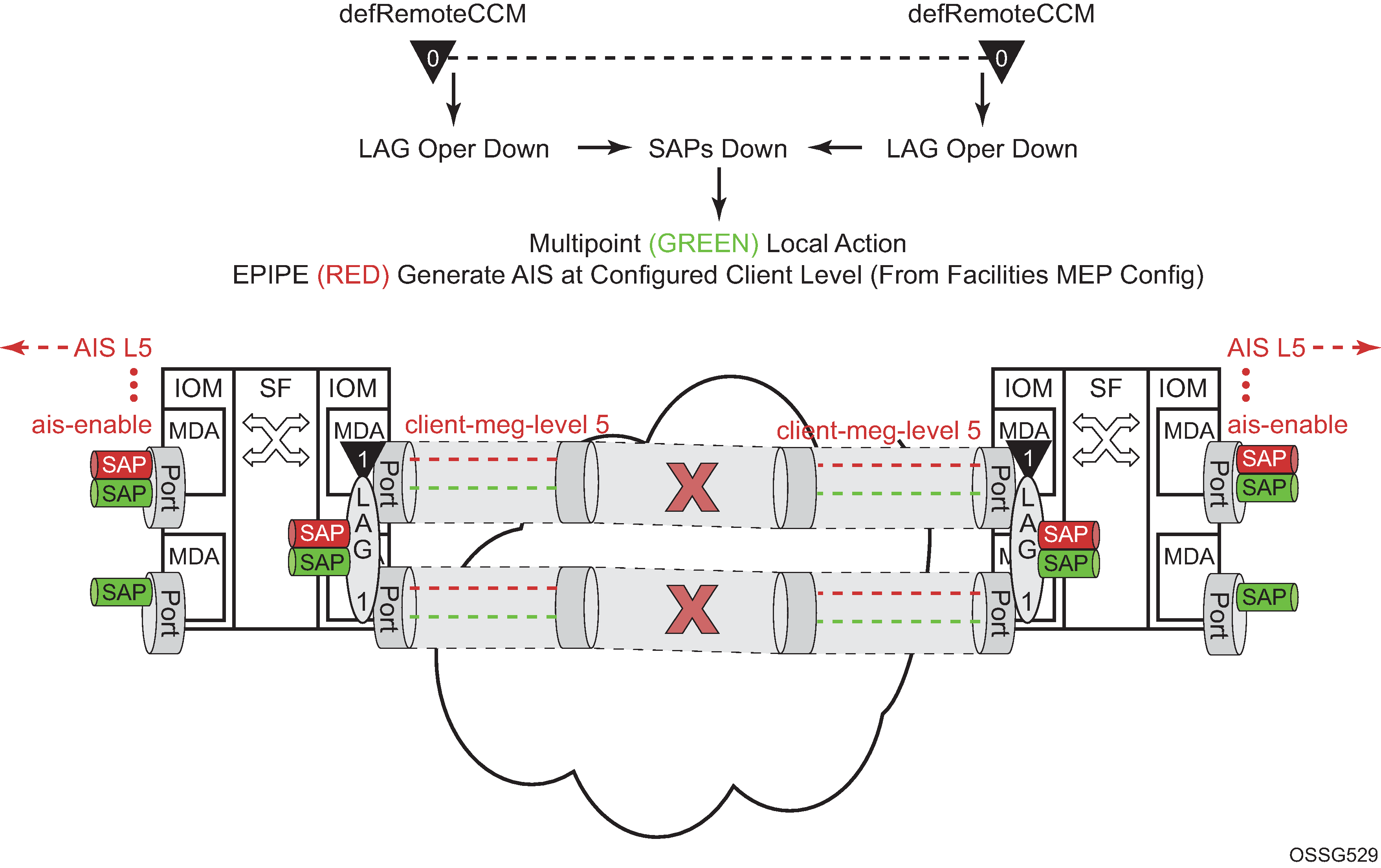
Fault handling LAG MEP, provides an example how an ETH-CFM failure reacts with the various services that share that LAG. There is only one way the LAG state can trigger the propagation of failure, and that is using ETH-AIS. The carrier must enable CCM at the LAG level and a ETH-CCM defect condition exists. The red Epipe service generates AIS as a result of the LAG failure using the client-meg-level command option configured on the LAG facility MEP. The green multipoint service takes location-configured action when the SAP transitions to the down operational state.
LAG-based MEP are supported for MultiChassis LAG (MC-LAG) configurations.
A LAG facility MEP must not be configured with facility-fault when it is applied to an MC-LAG. Traffic goes into a black hole when the LAG Facility MEP enters a defect state. The LAG enters an operational down state but the MC-LAG does not switch over to the peer node. This restriction does not include Tunnel Facility MEPs which are applied to a LAG with an outer VLAN. Tunnel facility MEPs do not control the operational state of the LAG because they are outer VLAN specific.
LAG MEP example uses a port-based MEP to validate port-to-port connectivity.
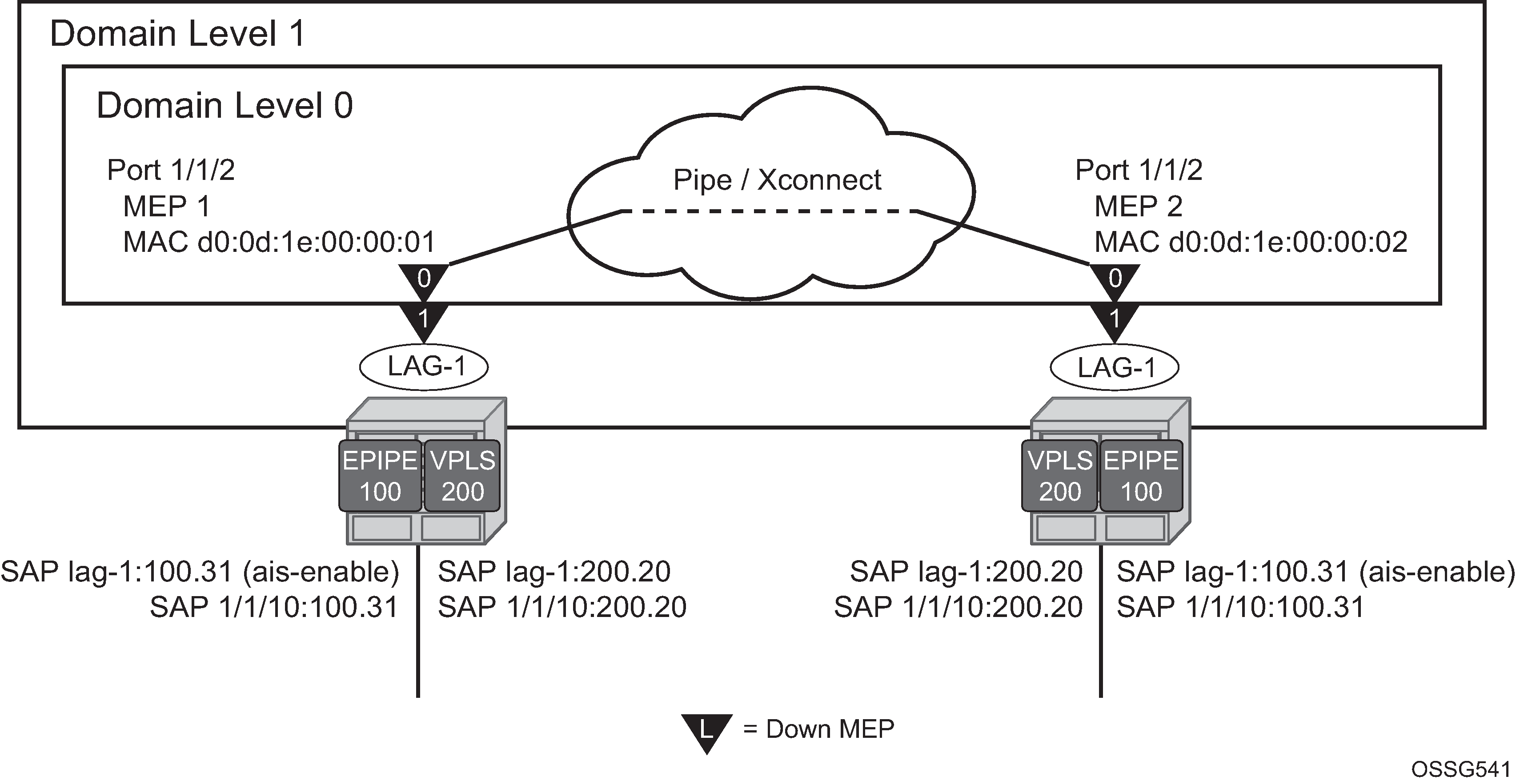
With the introduction of the LAG, the port no longer has direct control over the services SAPs. The AIS has been disabled from the port for this reason. The low-priority-defect condition has been modified to react to all defect conditions ‟allDef”, avoiding the unidirectional issue demonstrated in the previous port-based MEP example. A LAG MEP is built on top of the LAG with the facility-fault command option and enabling AIS with the associated client-meg-level. This allows the Epipe services to generate AIS when the LAG MEP enters any defect condition. This example introduce the use of a VPLS service. VPLS, IES and VPRN services do not support the generation of AIS as a result of a facility MEP failure. However, all service SAPs which correspond to the failed facility transition to a down state. Epipe service also generates AIS in this example.
Node1 configuration (MD-CLI)
[ex:/configure eth-cfm]
A:admin@node-1# info
    domain "1" {
        level 1
        format none
        association "1" {
            icc-based "FacilityLag01"
            ccm-interval 1s
            remote-mep 22 {
            }
        }
    }
    domain "10" {
        level 0
        format none
        association "1" {
            icc-based "FacilityPort0"
            ccm-interval 1s
            remote-mep 2 {
            }
        }
    }
[ex:/configure port 1/1/2]
A:admin@node-1# info
    admin-state enable
    ethernet {
        autonegotiate limited
        mode access
        encap-type qinq
        eth-cfm {
            mep md-admin-name "10" ma-admin-name "1" mep-id 1 {
                admin-state enable
                mac-address d0:0d:1e:00:00:01
                low-priority-defect all-def
                ccm true
                facility-fault true
                }
            }
        }
    }
[ex:/configure lag "lag-1"]
A:admin@node-1# info
    mode access
    admin-state enable
    encap-type qinq
    eth-cfm {
        mep md-admin-name "1" ma-admin-name "1" mep-id 11 {
            admin-state enable
            low-priority-defect all-def
            ccm true
            facility-fault true
            ais {
                client-meg-level [5]
            }
        }
    }
    port 1/1/2 {
    }

[ex:/configure service]
A:admin@node-1# info
    customer "1" {
        description "Default customer"
    epipe "100" {
        admin-state enable
        customer "1"
        sap 1/1/10:100.31 {
        }
        sap lag-1:100.31 {
            eth-cfm {
                ais true
            }
        }
    }
    vpls "200" {
        admin-state enable
        customer "1"
        stp {
            admin-state disable
        }
        sap 1/1/10:200.20 {
        }
        sap lag-1:200.20 {
        }
    }
Node1 configuration (classic CLI)
A:node-1>config>eth-cfm# info
----------------------------------------------
        domain 1 format none level 1
            association 1 format icc-based name "FacilityLag01"
                ccm-interval 1
                remote-mepid 22
            exit
        exit
        domain 10 format none level 0
            association 1 format icc-based name "FacilityPort0"
                ccm-interval 1
                remote-mepid 2
            exit
        exit
----------------------------------------------

A:node-1>config>port# info
----------------------------------------------
        ethernet
            autonegotiate limited
            mode access
            encap-type qinq
            eth-cfm
                mep 1 domain 10 association 1
                    facility-fault
                    ccm-enable
                    low-priority-defect allDef
                    mac-address d0:0d:1e:00:00:01
                    no shutdown
                exit
            exit
        exit
        no shutdown
----------------------------------------------

A:node-1>config>lag# info
----------------------------------------------
        mode access
        encap-type qinq
        eth-cfm
            mep 11 domain 1 association 1
                ais-enable
                    client-meg-level 5
                exit
                ccm-enable
                facility-fault
                low-priority-defect allDef
                no shutdown
            exit
        exit
        port 1/1/2
        no shutdown
----------------------------------------------

A:node-1>config>service# info
----------------------------------------------
        customer 1 create
            description "Default customer"
        exit
        epipe 100 customer 1 create
            sap 1/1/10:100.31 create
            exit
            sap lag-1:100.31 create
                eth-cfm
                    ais-enable
                exit
            exit
            no shutdown
        exit
        vpls 200 customer 1 create
            stp
                shutdown
            exit
            sap 1/1/10:200.20 create
            exit
            sap lag-1:200.20 create
            exit
            no shutdown
        exit
----------------------------------------------
Node2 configuration (MD-CLI)
[ex:/configure eth-cfm]
A:admin@node-2# info
    domain "1" {
        level 1
        format none
        association "1" {
            icc-based "FacilityLag01"
            ccm-interval 1s
            remote-mep 11 {
            }
        }
    }
    domain "10" {
        level 0
        format none
        association "1" {
            icc-based "FacilityPort0"
            ccm-interval 1s
            remote-mep 1 {
            }
        }
    }
[ex:/configure port 1/1/2]
A:admin@node-2# info
    admin-state enable
    ethernet {
        autonegotiate limited
        mode access
        encap-type qinq
        eth-cfm {
            mep md-admin-name "10" ma-admin-name "1" mep-id 2 {
                admin-state enable
                mac-address d0:0d:1e:00:00:02
                low-priority-defect all-def
                ccm true
                facility-fault true
                }
            }
        }
    }
[ex:/configure lag "lag-1"]
A:admin@node-2# info
    admin-state enable
    encap-type qinq
    eth-cfm {
        mep md-admin-name "1" ma-admin-name "1" mep-id 22 {
            admin-state enable
            low-priority-defect all-def
            ccm true
            facility-fault true
            ais {
                client-meg-level [5]
            }
        }
    }
    port 1/1/2 {
    }

[ex:/configure service]
A:admin@node-2# info
    customer "1" {
        description "Default customer"
    epipe "100" {
        admin-state enable
        customer "1"
        sap 1/1/10:100.31 {
        }
        sap lag-1:100.31 {
            eth-cfm {
                ais true
            }
        }
    }
    vpls "200" {
        admin-state enable
        customer "1"
        stp {
            admin-state disable
        }
        sap 1/1/10:200.20 {
        }
        sap lag-1:200.20 {
        }
    }
Node2 configuration (classic CLI)
A:node-2>config>eth-cfm# info
----------------------------------------------
        domain 1 format none level 1
            association 1 format icc-based name "FacilityLag01"
                ccm-interval 1
                remote-mepid 11
            exit
        exit
        domain 10 format none level 0
            association 1 format icc-based name "FacilityPort0"
                ccm-interval 1
                remote-mepid 1
            exit
        exit
----------------------------------------------

A:node-2>config>port# info
----------------------------------------------
        ethernet
            mode access
            encap-type qinq
            eth-cfm
                mep 2 domain 10 association 1
                    facility-fault
                    ccm-enable
                    low-priority-defect allDef
                    mac-address d0:0d:1e:00:00:02
                    no shutdown
                exit
            exit
            autonegotiate limited
        exit
        no shutdown
----------------------------------------------

A:node-2>config>lag# info
----------------------------------------------
        mode access
        encap-type qinq
        eth-cfm
            mep 22 domain 1 association 1
                ais-enable
                    client-meg-level 5
                exit
                facility-fault
                ccm-enable
                low-priority-defect allDef
                no shutdown
            exit
        exit
        port 1/1/2
        no shutdown
----------------------------------------------

A:node-2>config>service# info
----------------------------------------------
        customer 1 create
            description "Default customer"
        exit
        epipe 100 customer 1 create
            sap 1/1/10:100.31 create
            exit
            sap lag-1:100.31 create
                eth-cfm
                    ais-enable
                exit
            exit
            no shutdown
        exit
        vpls 200 customer 1 create
            stp
                shutdown
            exit
            sap 1/1/10:200.20 create
            exit
            sap lag-1:200.20 create
            exit
            no shutdown
        exit
----------------------------------------------
A fault is introduced that only affects the LAG MEP. The port MEP continues to validate the port, meaning that the port remains operationally up and the lag transitions to operation down. The LAG transition causes all the SAPs tied to the LAG to transition to down. The VPLS service reacts normally with the configured behavior as a result of a SAP down condition. The Epipe SAP also transitions to down, causing the operational state of the Epipe service to transition to down. In this case, AIS is enabled under the SAP in the service those AIS packets are still generated out the mate SAP.
Output from one of the nodes is included below. Because both react in the same manner, output from both nodes is not shown.
Node1 outputs
The following outputs display information for the Node1 example configuration.
Use the following command to display port information.
show port===============================================================================
Ports on Slot 1
===============================================================================
Port Admin Link Port Cfg Oper LAG/ Port Port Port C/QS/S/XFP/
Id State State MTU MTU Bndl Mode Encp Type MDIMDX
-------------------------------------------------------------------------------
...
1/1/2 Up Yes Up 1522 1522 - accs qinq xcme
...Use the following command to display information for the specified maintenance endpoint, maintenance domain, and maintenance association.
show eth-cfm mep 11 domain 1 association 1===============================================================================
Eth-Cfm MEP Configuration Information
===============================================================================
Md-index : 1 Direction : Down
Ma-index : 1 Admin : Enabled
MepId : 11 CCM-Enable : Disabled
Port : lag-1 VLAN : 0
Description : (Not Specified)
FngState : fngDefectReported ControlMep : False
LowestDefectPri : allDef HighestDefect : defRDICCM
Defect Flags : bDefRDICCM
Mac Address : 90:f3:ff:00:01:41 ControlMep : False
CcmLtmPriority : 7
CcmTx : 4428 CcmSequenceErr : 0
Fault Propagation : disabled FacilityFault : Notify
MA-CcmInterval : 1 MA-CcmHoldTime : 0ms
Eth-1Dm Threshold : 3(sec) MD-Level : 1
Eth-Ais: : Enabled Eth-Ais Rx Ais: : No
Eth-Ais Tx Priorit*: 7 Eth-Ais Rx Interv*: 1
Eth-Ais Tx Interva*: 1 Eth-Ais Tx Counte*: 1085
Eth-Ais Tx Levels : 5
Eth-Tst: : Disabled
...Use the following command to display the ETH-CFM facility information.
show service sap-using eth-cfm facility===============================================================================
Service ETH-CFM Facility Information
===============================================================================
SapId SvcId SAP AIS SAP Tunnel SVC Tunnel
Fault Fault
-------------------------------------------------------------------------------
lag-1:100.31 100 Enabled Accept Ignore
lag-1:200.20 200 Disabled Accept Ignore
-------------------------------------------------------------------------------
No. of Facility SAPs: 2
=============================================================================== Use the following command to display the CFM stack table facility information.
show eth-cfm cfm-stack-table facility===============================================================================
CFM Stack Table Defect Legend:
R = Rdi, M = MacStatus, C = RemoteCCM, E = ErrorCCM, X = XconCCM, A = AisRx
===============================================================================
CFM Facility Port Stack Table
===============================================================================
Port Tunnel Lvl Dir Md-index Ma-index MepId Mac-address Defect
-------------------------------------------------------------------------------
1/1/2 0 0 Down 10 1 1 d0:0d:1e:00:00:01 ------
===============================================================================
===============================================================================
CFM Facility LAG Stack Table
===============================================================================
Lag Tunnel Lvl Dir Md-index Ma-index MepId Mac-address Defect
-------------------------------------------------------------------------------
lag-1 0 1 Down 1 1 11 90:f3:ff:00:01:41 R-----
===============================================================================
Tunnel-based MEP
The concept of a logical tunnel carrying many unique and individual services has been deployed in many networks on QinQ encapsulated access ports where the outer VLAN represents the common transports and the inner VLAN represents the specific service. Typically, the tunnel transparently passes frames from multiple services through some common network. Tunnel MEPs are logically configured on the Port or LAG and outer VLAN for access ports use QinQ Ethernet encapsulation. Service processing is done after the tunnel MEP. This means that any service-based MEPs are required to be a higher level than that of the tunnel MEP. Tunnel MEPs are only supported on LAGs that are configured with QinQ encapsulation and must specify the outer VLAN.
The Tunnel MEP must validate connectivity between the tunnel end points. As with all facility MEPs, this is a point-to-point relationship between the local MEP and one remote MEP. By default, the MEP configured at the tunnel level performs only alarming functions. Actionable functions such as AIS, SAP transition, and fault propagation requires the user to enable these functions.
The tunnel MEP must first be configured to take action when the MEP enters a fault state, similar to all other facilities MEPs. For the individual services to share the fate of the tunnel, each service must accept the facility MEP state. This is service-dependent and depends on the needed goals. Services share the tunnel fate based on the lag-id and the outer VLAN.
Epipe services support the ais-enable command option on the SAP. Enabling this option generates AIS in the event the tunnel MEP has entered a fault state as a result of ETH-CC failure, similar to other facility MEPs. However, because the individual SAPs configured within the different services are not directly affected by the tunnel MEP, an additional configuration is necessary to perform local SAP transitions, in the case of VPLS, IES and VPRN services and OAM mapping functions for Epipe services.
The tunnel-fault service-level command configured on an Epipe allows SAP flags to be set and fault propagation and OAM mapping functions between technology. The operational state of the SAP remains up. The user needs to determine if the AIS generation of fault propagation is the best approach in their specific network. It is possible to configure both enabling AIS and tunnel-fault accept within the Epipe service. However, this may generate multiple ETH-CFM packets, or multiple actions as a result of a single failure.
The tunnel-fault accept service level option is also available under Epipe, VPLS and IES services hierarchy level within the CLI. This allows for a tunnel fault to share fate with these service SAPs. For the non-Epipe services, the SAP enters an operationally down state, and normal processing occurs as a result of the SAP transition. To generate any ETH-CC based fault propagation, suspend-cmm or use-int-stat-tlv, this requires service-based MEPs that are actively running CCM with a peer.
The tunnel-fault command options occur in two levels of the CLI hierarchy: service level and SAP level. Both of the levels within a service and within the SAP (whose underlying port and outer tag has a tunnel MEP) must be set to accept, in order to have the function enabled. By default the tunnel-fault is set to ignore at the service level and accept at the SAP level. This means that a single tunnel-fault accept at the service level enables fault operations for all SAPs in the service. The user is free to enable and disable on specific SAPs by choosing the ignore option under the individual SAP. The combination of accept at the service level and ignore at the SAP level prevents that specific SAP from recognizing fault. AIS generation for Epipe services is not controlled by the tunnel-fault command options.
Specific to tunnel MEPs, reception of AIS on the tunnel MEP causes AIS to be cut through to all Epipe services that have the ais-enabled command configured under the SAP. During a fault condition, it is important that the AIS configuration under the tunnel MEP not be modified. This causes increased network element CPU processing requirements and in scaled environments transitioning this command during a heavily loaded fault condition, where highly scaled SAPs are linked to the fate of the tunnel MEP, may cause the system to spend more than normal processing time to be spent dealing with this artificially induced clear and fault situation. It is not expected that users perform these types of tasks in production networks. Reception of AIS does not trigger a fault condition or AIS to be cut through when sub second CCM intervals have been configured on the Tunnel MEP.
Service-based MEPs may also be configured as normal for all services. They perform normal processing tasks, including service-based MEP with fault propagation.
As with all other facility MEPs, use only ETH-CFM functions to cause the Tunnel MEP to enter the fault state. Tunnel MEPs support sub second ccm-intervals on selected hardware. Tunnel MEPs must be configured with a direction of down. UP MEPs are not supported as part of the facility MEP concept.
LAG-based MEPs and LAG-based tunnel MEPs cannot be configured on the same LAG. Port-based MEPs may be configured on the LAG member ports of a tunnel MEP as long as they follow the requirements for port-based MEPs on LAG member ports. All those consideration are applicable here, including nesting and port-level control only without propagation.
Port-based MEPs and port-based tunnel MEPs cannot be configured on the same port.
LAG-based tunnel MEPs are supported in Multi-Chassis LAG (MC-LAG) configuration. However, sub second CCM enabled intervals should not be configured when the LAG-based tunnel MEP uses the transport of an MC-LAG. Only one second and above CCM intervals should be used. Not all platforms support sub second CCM enable tunnel MEPs.
Tunnel MEPs are meant to propagate fault from one segment to the other for Epipe services. Tunnel concepts and encapsulation shows how individual Epipes have SAPs connecting to a legacy network. A MEP is configured at the tunnel level and peers with a single remote peer MEP.
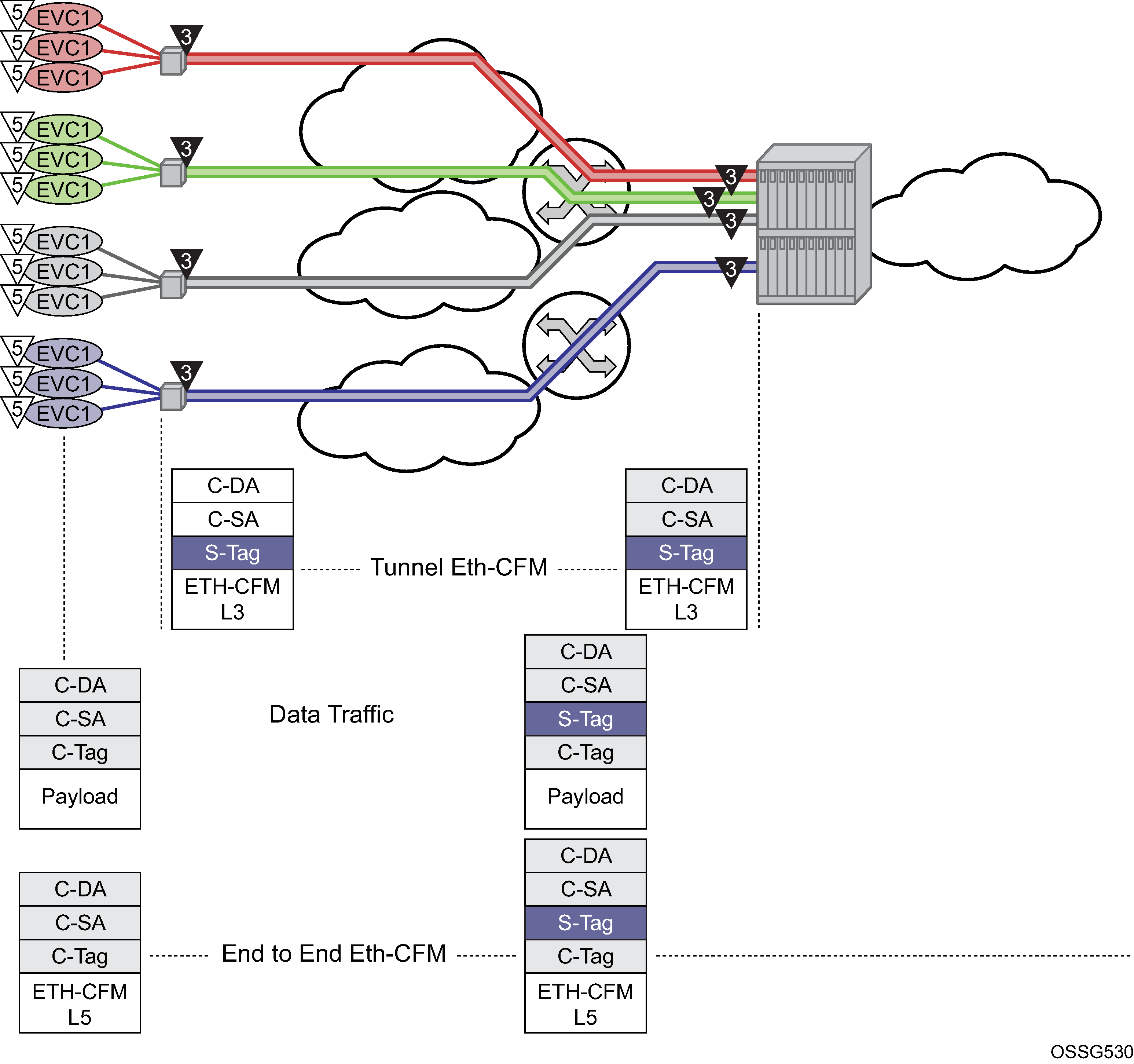
This is only one example of a tagged service. The principles of a tunnel MEP may be applied to other service as applicable. Remember that tunnel MEPs are only supported on LAGs that are configured with QinQ encapsulation and must have an outer VLAN.
Individual services can be monitored end-to-end by placing a MEP on the service endpoint at the CPE, denoted by the MEP at level 5 on the individual EVC (customer levels 5-7). The Network Interface Demarcation (NID) typically places a single tag, outer or only, on the customer traffic. This is cross connected to the correct connection in the access network and eventually arrive on the Ethernet Aggregation Switch. The connection between the legacy or access network and the aggregation switch must be either a LAG bundle or MC-LAG in order for tunnel MEPs to be configured.
Because there can be a large number of services transported by a single tunnel, the MEP executing at the tunnel-level reduces network overhead and simplifies the configuration.
A SAP is needed in order for the Tunnel MEP to extract the tunnel MEP ETH-CFM packets at the appropriate level. No SAP record is created by default. A service must already exist that includes a SAP in the form lag-id:vid.* or lag-id:vid.0 where the vid matches the outer VLAN in which the tunnel is to monitor. Because the ETH-CFM traffic arrives at the Ethernet aggregation node as a single outer tag with no inner tag, the user may want to consider the ability to configure the lag-id:vid.0 to accept untagged only frames with the matching outer tag and no inner tag.
In the classic CLI, use the following global command to enable this functionality.
configure system ethernet new-qinq-untagged-sapBy default both the vid.* and vid.0 accepts all packets that match the outer vid and any inner vid. If no SAP record exists for this VLAN, one must be created manually. Manually creating this SAP requires a service context. Nokia recommends that an Epipe service be configured with this single SAP, preventing any flooding of packets. It is possible to use a VPLS instance and combine many tunnel SAP records into a single service instance. However, configuration errors may result in leakage because of the multipoint nature of a VPLS service. Regardless of the service type chosen, it should be in a shutdown state. Also, normal ETH-CFM rules apply. ETH-CFM packets arriving on the SAP passes all ETH-CFM packets at and below the tunnel MEP to the ETH-CFM application for processing.
The goal of a Tunnel MEP is to validate an attachment circuit and relate the state to services that share the same LAG and outer VLAN to other services across the network. Tunnel MEPs are not intended for propagating fault between two endpoints that share the same LAG and outer VLAN. For this reason, locally switched circuits that share the same LAG and the same outer tag must not use the ais-enable function under those SAPs. As an example, lag-1 may have two SAPs associated with it: lag-1:1.1 and lag-1:1.2. These two SAP represent two different endpoints on the same LAG using the same outer VLAN. In this case, if the ais-enable is configured under both SAPs, AIS functionality does not work properly. Normal fault propagation could be used in this case instead. Because the tunnel MEP is validating the common physical path and these two MEPs share the common physical path, there is no reason to propagate fault. Service-based MEPs could be configured on the endpoints to validate the connectivity between the two endpoints when this type of model is deployed. However, two SAPs that are connected to different LAGs is a supported configuration. An example of this would be lag-1:1.1 and lag-2:1.1.
Sub second Tunnel MEPs are monitored for every three seconds to ensure that they are not continuously bouncing and consuming an unfair allocation of ETH-CFM resources. A sub second MEP is only allowed three operational status changes in a three second window before holding the state for the remaining time in that window. Messages are paced from Tunnel MEPs. Fault propagation depends on factors such as how busy the node is, or how scaled the node configuration is.
Five percent of the operational/negotiated port speed not physical speed is available for Tunnel MEP control traffic. When applying this to the LAG-based Tunnel MEPs the five percent is derived from the lowest speed of a single member port in the bundle. If this bandwidth percentage required for ETH-CFM is exceeded the ETH-CFM packets are not able to be sent and failures occur. As an example, a physical port of 1Gb/s that has negotiated an operational speed of 100 Mb/s with a peer is allowed to send up to a maximum of 5 Mb/s of Tunnel MEP control traffic.
Tunnel MEP example shows how fate can be shared between the Tunnel MEP and the services configured on the same LAG and outer VLAN.
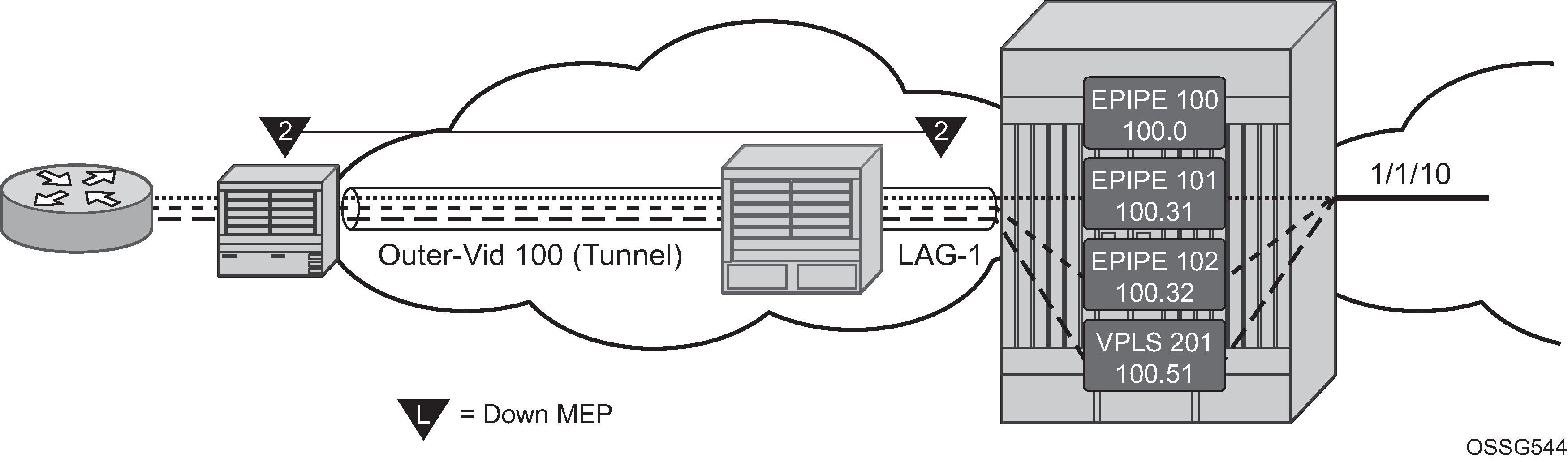
In this example, a single Tunnel, LAG-1 outer VLAN 100, carries three services. Epipe 101, Epipe 102 and VPLS 201 are the service extraction points on the aggregation node. Epipe 100 is the extraction point for the Tunnel MEP ETH-CFM traffic. This is a single SAP Epipe that is operationally shutdown. One common configuration error when using Tunnel MEPs is the lack extraction on the aggregation node, causing unidirectional failures. The aggregation node is sending ETH-CFM traffic to the NID, but is not extracting the eth-cfm traffic that the NID is sending.
Epipe 101 is configured to accept the tunnel MEP fate and generate AIS.
Epipe 102 is configured to accept the tunnel MEP state and apply fault propagation rules. If the network-side mate were an SDP binding, then the applicable setting of the LDP status bits are in the header. Because this example uses an Ethernet SAP as the mate, and only tunnel fault-accept is configured with no ais-enable, only the SAP flag is set to indicate an error.
VPLS 201 also shares the fate of the tunnel MEP. The tunnel-fault accept transitions the SAP to operationally down. Any configured event that occurs because of a SAP down for the VPLS also occur.
Only the configuration for the aggregation node is shown below. The NID configuration is not required to show how this function works.
Configuration of the aggregation node (classic CLI)
A:node-2>config>eth-cfm# info
----------------------------------------------
        domain 2 format none level 2
            association 1 format icc-based name "FacilityTun01"
                ccm-interval 1
                remote-mepid 101
            exit
        exit
----------------------------------------------

A:node-2>config>lag# info
----------------------------------------------
        mode access
        encap-type qinq
        eth-cfm
            mep 100 domain 2 association 1 vlan 100
                description "Tunnel Facility MEP - Do NOT Delete"
                ais-enable
                    client-meg-level 5
                exit
                facility-fault
                ccm-enable
                low-priority-defect allDef
                no shutdown
            exit
        exit
        port 1/1/2
        no shutdown
----------------------------------------------

A:node-2>config>service# info
----------------------------------------------
        customer 1 create
            description "Default customer"
        exit
        epipe 100 customer 1 create
            shutdown
            description "Tunnel Extraction Service"
            sap lag-1:100.0 create
            exit
        exit
        epipe 101 customer 1 create
            description "Customer Service 100.31"
            sap 1/1/10:100.31 create
            exit
            sap lag-1:100.31 create
                eth-cfm
                    ais-enable
                exit
            exit
            no shutdown
        exit
        epipe 102 customer 1 create
            description "Customer Service 100.32"
            eth-cfm
                tunnel-fault accept
            exit
            sap 1/1/10:100.32 create
            exit
            sap lag-1:100.32 create
            exit
            no shutdown
        exit
        vpls 201 customer 1 create
            description "Customer Service 100.51"
            stp
                shutdown
            exit
            eth-cfm
                tunnel-fault accept
            exit
            sap 1/1/10:100.51 create
            exit
            sap lag-1:100.51 create
            exit
            no shutdown
        exit
----------------------------------------------
Use the following command to display the ETH-CFM MEP configuration information.
show eth-cfm mep 100 domain 2 association 1===============================================================================
Eth-Cfm MEP Configuration Information
===============================================================================
Md-index : 2 Direction : Down
Ma-index : 1 Admin : Enabled
MepId : 100 CCM-Enable : Enabled
Port : lag-1 VLAN : 100
Description : Tunnel Facility MEP - Do NOT Delete
FngState : fngReset ControlMep : False
LowestDefectPri : allDef HighestDefect : none
Defect Flags : None
Mac Address : 90:f3:ff:00:01:41 ControlMep : False
CcmLtmPriority : 7
CcmTx : 3958 CcmSequenceErr : 0
Fault Propagation : disabled FacilityFault : Notify
MA-CcmInterval : 1 MA-CcmHoldTime : 0ms
Eth-1Dm Threshold : 3(sec) MD-Level : 2
Eth-Ais: : Enabled Eth-Ais Rx Ais: : No
Eth-Ais Tx Priorit*: 7 Eth-Ais Rx Interv*: 1
Eth-Ais Tx Interva*: 1 Eth-Ais Tx Counte*: 175
Eth-Ais Tx Levels : 5
Eth-Tst: : Disabled
Redundancy:
MC-LAG State : n/a
CcmLastFailure Frame:
None
XconCcmFailure Frame:
None
=============================================================================== Use the following information to display the CFM facility LAG stack information.
show eth-cfm cfm-stack-table facility all-tunnel-meps===============================================================================
CFM Stack Table Defect Legend:
R = Rdi, M = MacStatus, C = RemoteCCM, E = ErrorCCM, X = XconCCM, A = AisRx
===============================================================================
CFM Facility LAG Stack Table
===============================================================================
Lag Tunnel Lvl Dir Md-index Ma-index MepId Mac-address Defect
-------------------------------------------------------------------------------
lag-1 100 2 Down 2 1 100 90:f3:ff:00:01:41 ------
===============================================================================Use the following command to display the Service ETH-CFM facility information.
show service sap-using eth-cfm facility===============================================================================
Service ETH-CFM Facility Information
===============================================================================
SapId SvcId SAP AIS SAP Tunnel SVC Tunnel
Fault Fault
-------------------------------------------------------------------------------
lag-1:100.0 100 Disabled Accept Ignore
lag-1:100.31 101 Enabled Accept Ignore
lag-1:100.32 102 Disabled Accept Accept
lag-1:100.51 201 Disabled Accept Accept
-------------------------------------------------------------------------------
No. of Facility SAPs: 4
===============================================================================When the tunnel MEP enters a fault state:
-
Epipe 101 starts to generate AIS out the mate sap.
-
Epipe 102 SAP flag is set.
-
VPLS 201 SAP goes down.
The following examples show output from one of the nodes. Because both react in the same manner output from both nodes is not required.
Use the following command to display CFM facility LAG stack information.
show eth-cfm cfm-stack-table facility all-tunnel-meps===============================================================================
CFM Stack Table Defect Legend:
R = Rdi, M = MacStatus, C = RemoteCCM, E = ErrorCCM, X = XconCCM, A = AisRx
===============================================================================
CFM Facility LAG Stack Table
===============================================================================
Lag Tunnel Lvl Dir Md-index Ma-index MepId Mac-address Defect
-------------------------------------------------------------------------------
lag-1 100 2 Down 2 1 100 90:f3:ff:00:01:41 --C---
===============================================================================Use the following command to display ETH-CFM facility information.
show service sap-using eth-cfm facility tunnel 100===============================================================================
Service ETH-CFM Facility Information
===============================================================================
SapId SvcId SAP AIS SAP Tunnel SVC Tunnel
Fault Fault
-------------------------------------------------------------------------------
lag-1:100.0 100 Disabled Accept Ignore
lag-1:100.31 101 Enabled Accept Ignore
lag-1:100.32 102 Disabled Accept Accept
lag-1:100.51 201 Disabled Accept Accept
-------------------------------------------------------------------------------
No. of Facility SAPs: 4
===============================================================================Use the following command to display ETH-CFM MEP configuration information.
show eth-cfm mep 100 domain 2 association 1===============================================================================
Eth-Cfm MEP Configuration Information
===============================================================================
Md-index : 2 Direction : Down
Ma-index : 1 Admin : Enabled
MepId : 100 CCM-Enable : Enabled
Port : lag-1 VLAN : 100
Description : Tunnel Facility MEP - Do NOT Delete
FngState : fngDefectReported ControlMep : False
LowestDefectPri : allDef HighestDefect : defRemoteCCM
Defect Flags : bDefRemoteCCM
Mac Address : 90:f3:ff:00:01:41 ControlMep : False
CcmLtmPriority : 7
CcmTx : 4211 CcmSequenceErr : 0
Fault Propagation : disabled FacilityFault : Notify
MA-CcmInterval : 1 MA-CcmHoldTime : 0ms
Eth-1Dm Threshold : 3(sec) MD-Level : 2
Eth-Ais: : Enabled Eth-Ais Rx Ais: : No
Eth-Ais Tx Priorit*: 7 Eth-Ais Rx Interv*: 1
Eth-Ais Tx Interva*: 1 Eth-Ais Tx Counte*: 215
Eth-Ais Tx Levels : 5
Eth-Tst: : Disabled
Redundancy:
MC-LAG State : n/a
CcmLastFailure Frame:
None
XconCcmFailure Frame:
None
===============================================================================Us the following command to display basic service information.
show service id 101 base===============================================================================
Service Basic Information
===============================================================================
Service Id : 101 Vpn Id : 0
Service Type : Epipe
Name : (Not Specified)
Description : Customer Service 100.31
Customer Id : 1
Last Status Change: 02/04/2010 15:53:12
Last Mgmt Change : 02/04/2010 16:31:00
Admin State : Up Oper State : Up
MTU : 1514
Vc Switching : False
SAP Count : 2 SDP Bind Count : 0
Per Svc Hashing : Disabled
Force QTag Fwd : Disabled
-------------------------------------------------------------------------------
Service Access & Destination Points
-------------------------------------------------------------------------------
Identifier Type AdmMTU OprMTU Adm Opr
-------------------------------------------------------------------------------
sap:1/1/10:100.31 qinq 1522 1522 Up Up
sap:lag-1:100.31 qinq 1522 1522 Up Up
===============================================================================Use the following command to display basic service information.
show service id 102 base===============================================================================
Service Basic Information
===============================================================================
Service Id : 102 Vpn Id : 0
Service Type : Epipe
Name : (Not Specified)
Description : Customer Service 100.32
Customer Id : 1
Last Status Change: 02/04/2010 15:45:07
Last Mgmt Change : 02/04/2010 16:30:43
Admin State : Up Oper State : Up
MTU : 1514
Vc Switching : False
SAP Count : 2 SDP Bind Count : 0
Per Svc Hashing : Disabled
Force QTag Fwd : Disabled
-------------------------------------------------------------------------------
Service Access & Destination Points
-------------------------------------------------------------------------------
Identifier Type AdmMTU OprMTU Adm Opr
-------------------------------------------------------------------------------
sap:1/1/10:100.32 qinq 1522 1522 Up Up
sap:lag-1:100.32 qinq 1522 1522 Up Up
===============================================================================Use the following command to display SAP information.
show service id 102 sap lag-1:100.32===============================================================================
Service Access Points(SAP)
===============================================================================
Service Id : 102
SAP : lag-1:100.32 Encap : qinq
QinQ Dot1p : Default
Description : (Not Specified)
Admin State : Up Oper State : Up
Flags : OamTunnelMEPFault
Multi Svc Site : None
Last Status Change : 02/04/2010 15:45:07
Last Mgmt Change : 02/04/2010 15:44:26
-------------------------------------------------------------------------------
ETH-CFM SAP specifics
-------------------------------------------------------------------------------
Tunnel Faults : accept AIS : Disabled
MC Prop-Hold-Timer : n/a
===============================================================================Use the following command to display basic service information.
show service id 1 base===============================================================================
Service Basic Information
===============================================================================
Service Id : 1 Vpn Id : 0
Service Type : VPLS
Name : 1
Description : (Not Specified)
Customer Id : 1 Creation Origin : manual
Last Status Change: 05/08/2018 09:40:32
Last Mgmt Change : 05/08/2018 09:40:24
Etree Mode : Disabled
Admin State : Up Oper State : Up
MTU : 1514
SAP Count : 1 SDP Bind Count : 1
Snd Flush on Fail : Disabled Host Conn Verify : Disabled
SHCV pol IPv4 : None
Propagate MacFlush: Disabled Per Svc Hashing : Disabled
Allow IP Intf Bind: Disabled
Fwd-IPv4-Mcast-To*: Disabled Fwd-IPv6-Mcast-To*: Disabled
Mcast IPv6 scope : mac-based
Def. Gateway IP : None
Def. Gateway MAC : None
Temp Flood Time : Disabled Temp Flood : Inactive
Temp Flood Chg Cnt: 0
SPI load-balance : Disabled
TEID load-balance : Disabled
Src Tep IP : N/A
Vxlan ECMP : Disabled
VSD Domain : <none>
-------------------------------------------------------------------------------
Service Access & Destination Points
-------------------------------------------------------------------------------
Identifier Type AdmMTU OprMTU Adm Opr
-------------------------------------------------------------------------------
sap:1/1/c1/1:1 q-tag 9000 9000 Up Up
sdp:65:1 S(192.0.2.5) Spok 0 8974 Up Down
===============================================================================
* indicates that the corresponding row element may have been truncated.Router interface MEP
MEPs and associated on-demand troubleshooting functions act as router interfaces that are part of the base routing instance. This feature allows the user to verify Layer 2 transport that connects the Layer 3 interfaces.
Router interfaces MEPs are supported for all router interface instances (null port 1/1/1, dot1q port 1/1/3:vid, null LAG-lag-id and dot1q LAG-lag-id:vid).
The following illustration, Router MEP example, shows how a Router Facility MEP can be configured on a routed interface in the base router instance.
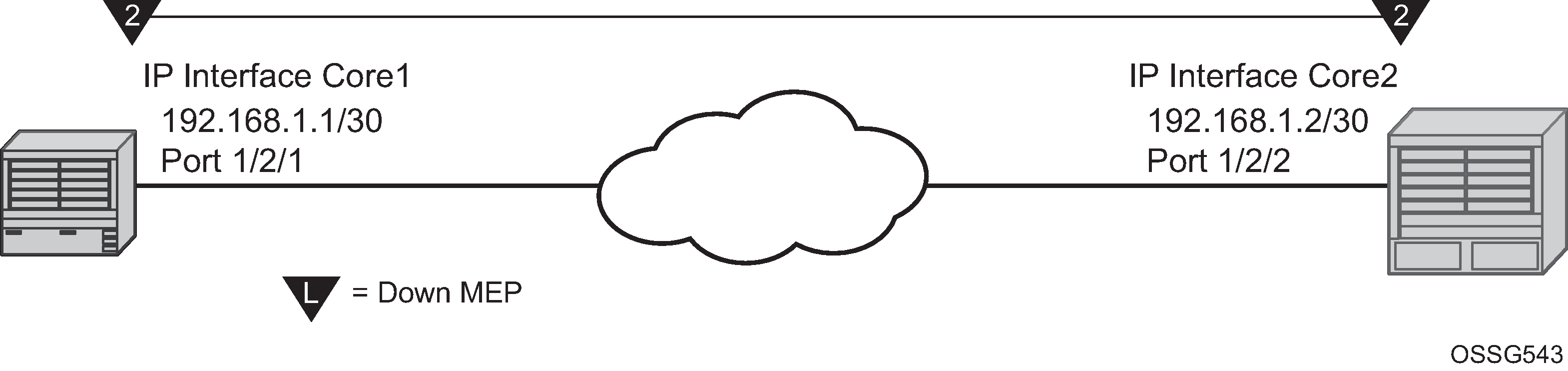
ETH-CFM tools for proactive management (ETH-CC), troubleshooting (Loopback, Linktrace, and so on) and profiling (Delay Measurement, and so on) are supported. The configuration and some ETH-CFM test commands are shown for Node1 (left). Following the on-demand test output, the configuration for Node 2 is included for completeness, without repeating the on-demand tests.
Node1 configuration (MD-CLI)
[ex:/configure port 1/2/1]
A:admin@node-1# info
    admin-state enable

[ex:/configure eth-cfm]
A:admin@node-1# info
    domain "2" {
        level 2
        format none
        association "2" {
            icc-based "FacilityRtr01"
        }
    }

[ex:/configure router "Base"]
A:admin@node-1# info
    interface "Core1" {
        port 1/2/1
        eth-cfm {
            mep md-admin-name "2" ma-admin-name "2" mep-id 1 {
                admin-state enable
                mac-address d0:0d:1e:00:00:01
            }
        }
        ipv4 {
            primary {
                address 192.168.1.1
                prefix-length 30
            }
        }
    }
Node1 configuration (classic CLI)
A:node-1>config>port# info
----------------------------------------------
        ethernet
        exit
        no shutdown
----------------------------------------------

A:node-1>config>eth-cfm# info
----------------------------------------------
        domain 2 format none level 2
            association 2 format icc-based name "FacilityRtr01"
            exit
        exit
----------------------------------------------

A:node-1>config>router# info
#--------------------------------------------------
echo "IP Configuration"
#--------------------------------------------------
        interface "Core1"
            address 192.168.1.1/30
            port 1/2/1
            eth-cfm
                mep 1 domain 2 association 2
                    mac-address d0:0d:1e:00:00:01
                    no shutdown
                exit
            exit
        exit
        interface "system"
        exit
----------------------------------------------
Use the following command to show CFM facility information stack information for all router interfaces.
show eth-cfm cfm-stack-table facility all-router-interfaces===============================================================================
CFM Stack Table Defect Legend:
R = Rdi, M = MacStatus, C = RemoteCCM, E = ErrorCCM, X = XconCCM, A = AisRx
===============================================================================
CFM Facility Interface Stack Table
===============================================================================
Interface Lvl Dir Md-index Ma-index MepId Mac-address Defect
-------------------------------------------------------------------------------
Core1 2 Down 2 2 1 d0:0d:1e:00:00:01 ------
===============================================================================Use the following command to show CFM facility interface stack information for all router interfaces.
show eth-cfm cfm-stack-table facility all-router-interfaces===============================================================================
CFM Stack Table Defect Legend:
R = Rdi, M = MacStatus, C = RemoteCCM, E = ErrorCCM, X = XconCCM, A = AisRx
===============================================================================
CFM Facility Interface Stack Table
===============================================================================
Interface Lvl Dir Md-index Ma-index MepId Mac-address Defect
-------------------------------------------------------------------------------
Core1 2 Down 2 2 1 d0:0d:1e:00:00:01 ------
===============================================================================
# oam eth-cfm loopback d0:0d:1e:00:00:02 mep 1 domain 2 association 2
send-count 5
Eth-Cfm Loopback Test Initiated: Mac-Address: d0:0d:1e:00:00:02, out service: 0
Sent 5 packets, received 5 packets [0 out-of-order, 0 Bad Msdu]
# oam eth-cfm linktrace d0:0d:1e:00:00:02 mep 1 domain 2 association
2
Index Ingress Mac Egress Mac Relay Action
----- -------------------- -------------------- ---------- ----------
1 D0:0D:1E:00:00:02 00:00:00:00:00:00 n/a terminate
----- -------------------- -------------------- ---------- ----------
No more responses received in the last 6 seconds.
# oam eth-cfm two-way-delay-test d0:0d:1e:00:00:02 mep 1 domain 2 association 2
Two-Way-Delay-Test Response:
Delay 1130 microseconds Variation 63 microseconds
# oam eth-cfm two-way-delay-test d0:0d:1e:00:00:02 mep 1 domain 2 association 2
Two-Way-Delay-Test Response:
Delay 1218 microseconds Variation 88 microsecondsNode2 configuration (MD-CLI)
[ex:/configure port 1/2/2]
A:admin@node-2# info
    admin-state enable

[ex:/configure eth-cfm]
A:admin@node-2# info
    domain "2" {
        level 2
        format none
        association "2" {
            icc-based "FacilityRtr01"
        }
    }

[ex:/configure router "Base"]
A:admin@node-2# info
    interface "Core2" {
        port 1/2/2
        eth-cfm {
            mep md-admin-name "2" ma-admin-name "2" mep-id 2 {
                admin-state enable
                mac-address d0:0d:1e:00:00:02
            }
        }
        ipv4 {
            primary {
                address 192.168.1.2
                prefix-length 30
            }
        }
    }
Node2 configuration (classic CLI)
A:node-2>config>port# info
----------------------------------------------
        ethernet
        exit
        no shutdown
----------------------------------------------

A:node-2>config>eth-cfm# info
----------------------------------------------
        domain 2 format none level 2
            association 2 format icc-based name "FacilityRtr01"
            exit
        exit
----------------------------------------------

A:node-2>config>router# info
#--------------------------------------------------
echo "IP Configuration"
#--------------------------------------------------
        interface "Core2"
            address 192.168.1.2/30
            port 1/2/2
            eth-cfm
                mep 2 domain 2 association 2
                    mac-address d0:0d:1e:00:00:02
                    no shutdown
                exit
            exit
        exit
        interface "system"
        exit
----------------------------------------------
Hardware support
This section applies to the 7750 SR and 7450 ESS. However, only the facility MEP has an IOM-specific requirement. SAPs and ports that are not configured as part of facility MEPs are not restricted to a specific IOM. For example, a Tunnel MEP would be required to meet the minimum IOM requirement, similar to the fated shared service SAPs. However, the mate or egress SAP or binding is not required to meet the facility MEP requirement. Of course, there may be other reasons why a mate SAP or binding requires specific IOM/IMM that are outside that of facility MEPs. Similarly, a LAG MEP requires all port members to meet the IOM/IMM requirements for facility MEPs.
Facility MEP support overview provides an overview of Facility MEP support.
| Port MEPs | Tunnel MEPs | LAG MEPs | Router MEPs | ||
|---|---|---|---|---|---|
| Port | LAG | ||||
Sub Second |
Yes |
Yes |
Yes |
Yes |
Yes |
Port: |
|||||
Hybrid Network Access |
Dot1q/QinQ Null/Dot1q Null/Dot1q/QinQ |
QinQ no QinQ |
QinQ no QinQ |
Dot1q/QinQ Null/Dot1q Null/Dot1q/QinQ |
Dot1q/QinQ Null/QinQ N/A |
CCM |
Yes |
Yes |
Yes |
Yes |
Yes |
Y.1731 PM Tools |
Yes |
Yes |
Yes |
Yes |
Yes |
AIS Reception |
— |
Yes |
Yes |
— |
— |
Facility Fault |
Controls port operational state Failure=Link Up Success=Up |
Controls shared fate service SAPs and Epipe AIS |
Controls Shared fate service SAPs and Epipe AIS |
Controls LAG operational state Failure=Oper: down, Success=Oper=up |
Controls IP interface operational state in reaction to CFM state |
Mutually Exclusive |
Mutually Exclusive |
||||
Sub-second CCM-enabled MEPs are platform-specific and may not be supported uniformly on the 7750 SR, 7450 ESS and 7950 XRS platforms. For those 7750 SR, 7450 ESS and 7950 XRS platforms which support sub-second CCM-enabled MEPs, this additional restriction is applied; QinQ tunnel MEPs require a minimum of SF/CPM3.
ETH-CFM and MC-LAG
By default, ETH-CFM Management Points (MEPs and MIPs) and MC-LAG operate independently. Nokia recommends not enabling fault propagation when the default behavior is in use. A global command is available to allow ETH-CFM the ability to track the state of the MC-LAG for MPs that are configured on MC-LAG ports. This feature does not allow MEPs to influence MC-LAG state. Because the MP relies heavily on the underlying MC-LAG construct, consideration must be given for the correct MC-LAG design and deployment. It is important to understand that the state of MC-LAG can be reflected in the state of the MPs which are configured on SAPs that are part MC-LAGs. For example, a SAP on a LAG that is part of an MC-LAG configuration can behave in a manner that more appropriately represents the MC-LAG.
ETH-CFM and MC-LAG default behavior
ETH-CFM MPs track the SAPs, bindings and facility independently. Therefore, when an MP is configured on a SAP which is not operationally up because of MC-LAG ETH-CFM defect, conditions are raised for what could be considered normal conditions. Independent processing UP MEP example shows the default behavior for a point-to-point service without regard for MC-LAG. In the case below, the two up MEPs operating at level 4 on the affected SAPs set the Interface-Status-TLV bit in the ETH-CC header to represent the isDown condition, assuming ETH-CC is executing between the peer MEPs. This is the correct action based on the ETH-CFM perspective, SAPs are operationally down.
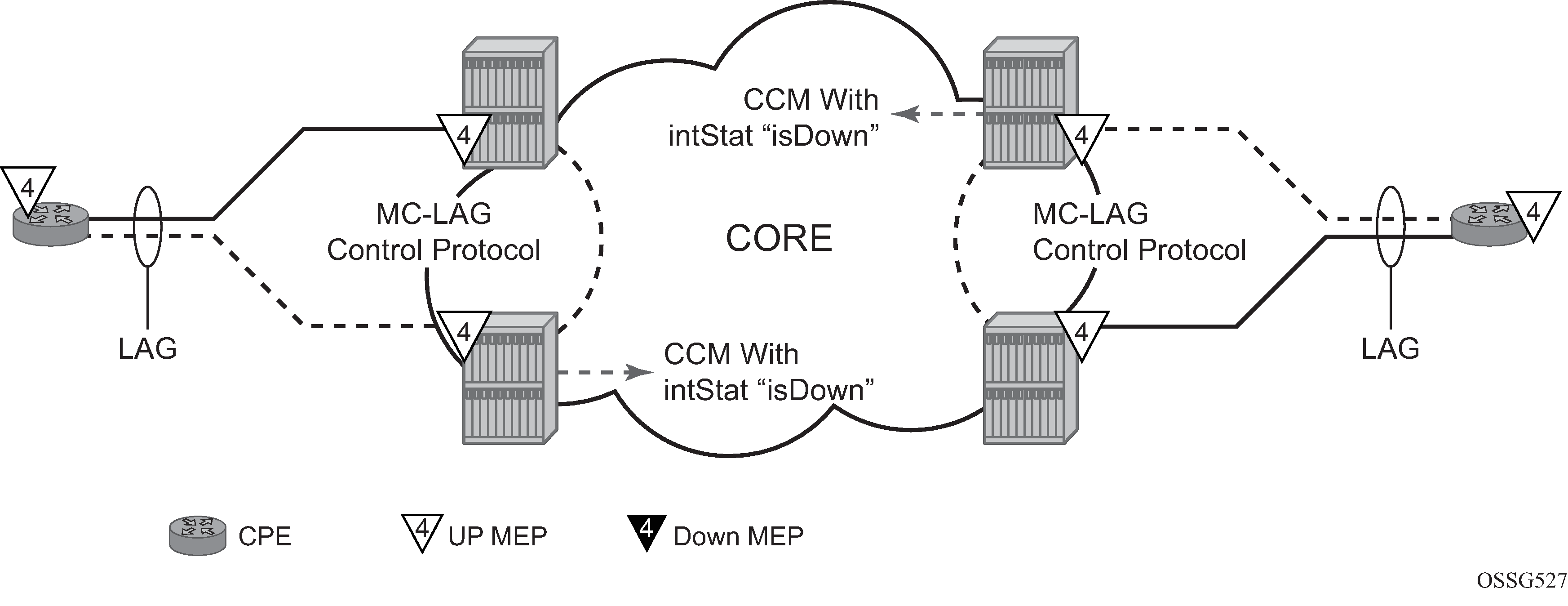
A similar condition exists if down MEPs are configured on the SAPs that are operationally down. Independent processing down MEP example shows how the same service configured with down MEPs would generate AIS, if enabled, toward the remote client at the configured client-meg-level, in the reverse direction of the MEP. This is also the correct behavior from the perspective ETH-CFM.
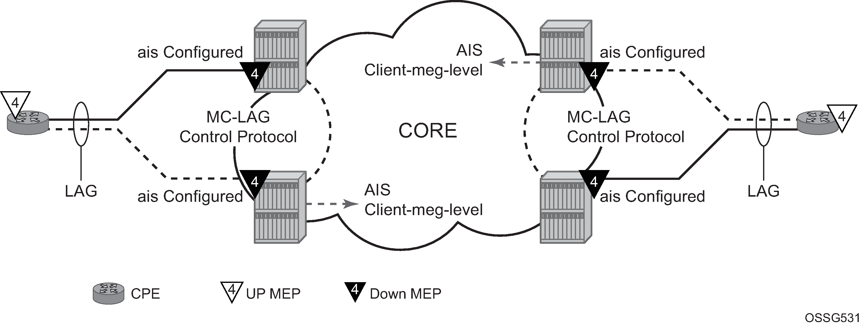
Linking ETH-CFM to MC-LAG state
Allowing ETH-CFM to understand the state of MC-LAG and adjusting the behavior of the MP (MEP and MIP) according to that state has benefits.
MC-LAG represents the two upstream nodes as a single system to the node terminating a standard LAG. Linking the ETH-CFM MPs to the state of the MC-LAG allows the user to configure MPs across the two boxes that appear the same. Under the default configuration, this would introduce various defect conditions to be raised and event conditions. However, when ETH-CFM is tracking the state of the MC-LAG, the MPs performs a role that represents the state of the resiliency mechanism.
Use the following system-wide command to enable this new behavior:
- MD-CLI
configure system eth-cfm redundancy mc-lag standby-mep true - classic
CLI
configure eth-cfm redundancy mc-lag standby-mep-shutdown
When a MP is part of the active MC-LAG system, it performs as a normal MP: terminating, generating, responding to, and processing all appropriate ETH-CFM packets. An MP that is on the standby MC-LAG node enters a pseudo-shutdown state. These MPs terminates all ETH-CFM that are part of the regular interception process, but does not process them. They are silently discarded. Also, an MP that exists on a standby MC-LAG system does not generate any ETH-CFM packets. All proactive and on-demand functions are blocked on the standby MC-LAG node. When scheduled tests are executed through SAA these test attempt to execute. The tests record failures as a result of the MEP state. These failures are not representative of the network.
This feature relies on the correct configuration, design, and deployment of the MC-LAG protocol. There are numerous optimizations and command options that are available as part of the MC-LAG functions. For example, by default, when a currently active MC-LAG port transitions to standby, by any means including manual user intervention, the remote node terminating the standard LAG sees the LAG transition because all ports in the LAG are down for an instance in time. This is standard LAG behavior does not change as a result of the linkage of MP state to MC-LAG state. This transition causes the propagation of faults for MEPs configured on that node.
ETH-CFM registers a fault propagation delay timer equal to propagate-hold-time under the configure eth-cfm redundancy mc-lag context (default of 1s) to delay notification of an event that may be a result of MC-LAG failover. This allows the system time to coordinate events and triggers that together represent the MC-LAG transition from active to standby.
A fixed timer value of 1s delays an UP MEP from announcing a SAP down condition through CCM Interface-Status-TLV bits, is Down. ETH-CFM maintains a status of last sent to the UP MEPs peer. When the SAP transitions either to UP or DOWN that fault is held for the fixed 1s interval and the last Interface-Status-TLV bits are set based on the previous transmission. If the condition, different from the previous sent, still exists at the end of the 1s fixed timer and when the next CCM interval expires, the representative value of the SAP is sent in the Interface-Status-TLV. These two timers help to smooth out network transitions at the cost of propagation and clearing of faults.
When a node with ETH-CFM linked to MC-LAG is transitioning from standby to active ETH-CFM assumes there are no underlying conditions for any of the SAPs that are now part of the newly activating MC-LAG. The initial notification to an UP MEPs peer does not include any faults. It assumes that the transitioning SAPs are stabilizing as the switchover proceeds. The fixed 1s timer starts and a second CCM PDU based on the UP MEPs interval is sent without any recognition of potential fault on the SAP. However, after the expiration of the fixed timer and on the next CCM-Interval, the Interface-Status-TLV represents the state of the SAP.
In scaled environments it is important to configure the propagation-hold-time and the CCM intervals to achieve the needed goals. If these timers are set too aggressively, then fault and defect conditions may be generated during times of network stabilization. The use of fault propagation and AIS transmission needs to be carefully considered in environments where MC-LAG protection mechanisms are deployed. Timer values do not guarantee that transitional state is not propagated to the peer. The propagation of such state may be more taxing and disruptive that allowing the transmission states to complete. For example, if AIS generation is being used in this type of solution the user should use a 60s AIS interval to avoid transitional state from being advertised.
AIS generation is paced in a first come first serve model not to exceed the system capability, scale is dependent on the type of system. If AIS is configured in an MC-LAG solution the user must make sure that the same MEPs on each system are configured to generate AIS and this number does not exceed the maximum. This would require the user to configure both nodes with the same MEPs that can generate AIS and not exceed the system capacity. If the nodes are configured differently or exceed the system scale there is a very high potential where a transition may see a different set of MEPs pacing out the AIS than the original set of MEPs. There is no synchronization of AIS state across nodes.
Administrative functions, like administratively down, are special cases. When the administrative state changes from up to down, the timer is bypassed and communication from ETH-CFM is immediate.
When an MP is configured in an MC-LAG environment, Nokia recommends that each aspect of the MP be configured the same, including MAC address. Also, although this may be obvious, both nodes participating in the MC-LAG requiring this functionality should include the following global command to avoid unpredictable behavior:
- MD-CLI
configure system eth-cfm redundancy mc-lag standby-mep true - classic
CLI
configure eth-cfm redundancy mc-lag standby-mep-shutdown
In summary, a SAP with ETH-CFM tracking the state of the MC-LAG represents the state of the MC-LAG. MPs configured on the standby MC-LAG ports enters a state similar to being administratively disabled. MPs on the MC-LAG ports on the active MC-LAG ports perform all normal processing.
The following illustration, shows how MEPS can be linked to MC-LAG state. In this example, a service MEP is created on the LAG SAP on NODE1 within service VPLS 100. The MEPs configured on the MC-LAG nodes within service 100 are both configured the same. Both MEPs use the same MEP-ID, the same MAC address.
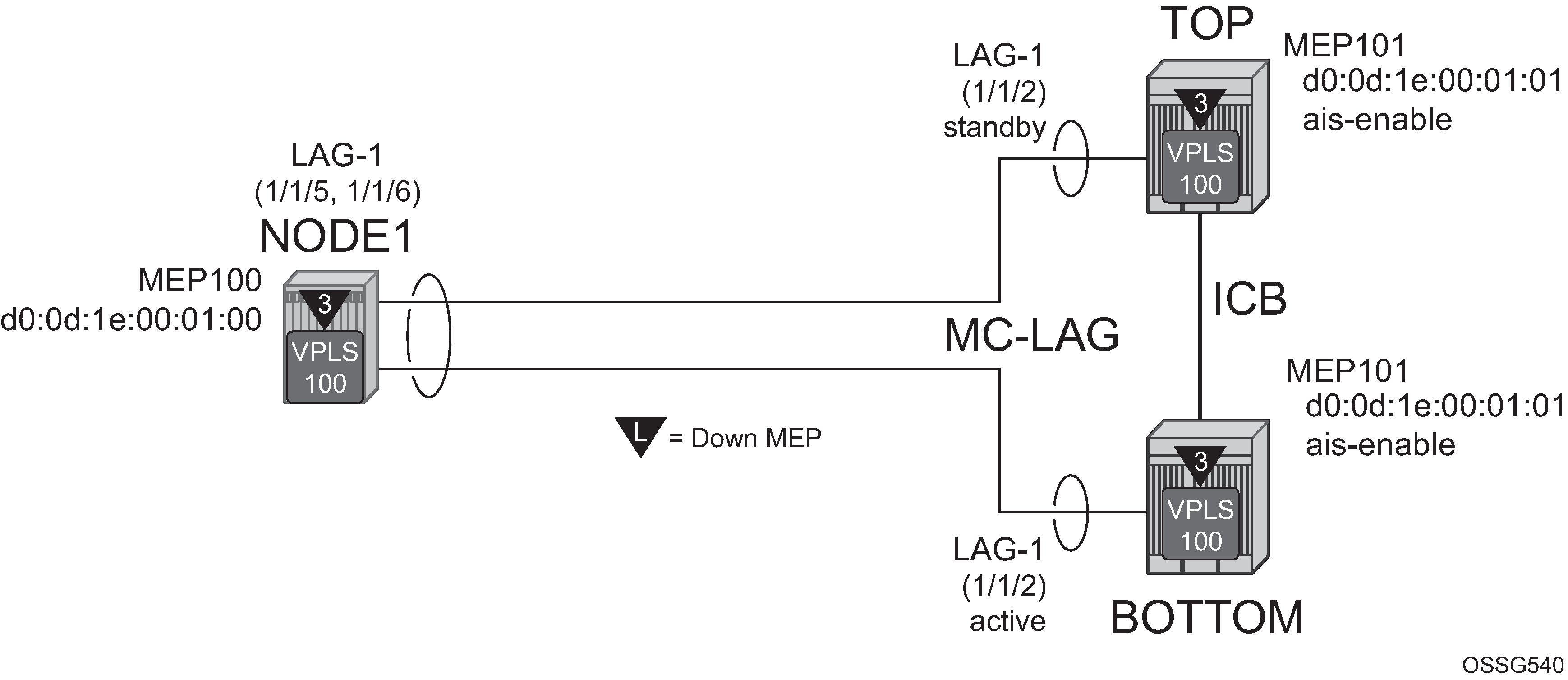
Only one of the MEPs on the MC-LAG nodes is active for VPLS service 100. The other MEP is in a shutdown mode, so that even when the MC-LAG is in standby and the port state is Link Up, the MEP is in a pseudo shutdown state.
The following configuration example is not meant to provide all possible MC-LAG configuration statement to tune each provider’s network. It does provide a base configuration to demonstrate the ETH-CFM feature.
Node1 configuration (MD-CLI)
[ex:/configure port 1/1/5]
A:admin@node-1# info
    ethernet {
        autonegotiate limited
        mode access
        encap-type qinq
    }

[ex:/configure port 1/1/6]
A:admin@node-1# info
    ethernet {
        autonegotiate limited
        mode access
        encap-type qinq
    }

[ex:/configure lag "lag-1"]
A:admin@node-1# info
    admin-state enable
    encap-type qinq
    mode access
    hold-time-down 10
    lacp {
        mode active
        administrative-key 32768
    }
    access {
        adapt-qos {
            mode link
        }
    }
    port 1/1/5 {
    }
    port 1/1/6 {
    }

[ex:/configure eth-cfm]
A:admin@node-1# info
...
    domain "3" {
        level 3
        format none
        association "1" {
            icc-based "03-0000000100"
            ccm-interval 1s
            bridge-identifier "100" {
            }
            remote-mep 101 {
            }
        }
    }
[ex:/configure service vpls "100"]
A:admin@node-1# info
...
    stp {
        admin-state disable
    }
    sap 1/1/3:100.100 {
    }
    sap lag-1:100.100 {
        eth-cfm {
            mep md-admin-name "3" ma-admin-name "1" mep-id 100 {
                direction down
                mac-address d0:0d:1e:00:01:00
                ccm true
            }
        }
    }
Node1 configuration (classic CLI)
A:node-1>config>port# info (both ports)
----------------------------------------------
        ethernet
            mode access
            encap-type qinq
            autonegotiate limited
        exit
        no shutdown
----------------------------------------------

A:node-1>config>lag# info
----------------------------------------------
     mode access
        encap-type qinq
        access
            adapt-qos link
        exit
        port 1/1/5
        port 1/1/6
        lacp active administrative-key 32768
        hold-time down 10
        no shutdown
----------------------------------------------

A:node-1>config>eth-cfm# info
----------------------------------------------
        domain 3 format none level 3
            association 1 format icc-based name "03-0000000100"
                bridge-identifier 100
                exit
            ccm-interval 1
            remote-mepid 101
            exit
        exit
----------------------------------------------

A:node-1>config>service>vpls# info
----------------------------------------------
            stp
                shutdown
            exit
            sap 1/1/3:100.100 create
            exit
            sap lag-1:100.100 create
                eth-cfm
                    mep 100 domain 3 association 1 direction down
                        ccm-enable
                        mac-address d0:0d:1e:00:01:00
                        no shutdown
                    exit
                exit
            exit
            no shutdown
----------------------------------------------
Top (MC-LAG Standby) configuration (MD-CLI)
[ex:/configure port 1/1/2]
A:admin@node-top# info
    ethernet {
        autonegotiate limited
        mode access
        encap-type qinq
    }

[ex:/configure lag "lag-1"]
A:admin@node-top# info
    admin-state enable
    encap-type qinq
    mode access
    hold-time-down 10
    lacp {
        mode active
        administrative-key 32768
    }
    access {
        adapt-qos {
            mode link
        }
    }
    port 1/1/2 {
    }

[ex:/configure router "Base"]
A:admin@node-top# info
    interface "Core2" {
        port 1/2/2
        ipv4 {
            primary {
                address 192.168.1.2
                prefix-length 30
            }
        }
    }

[ex:/configure redundancy]
A:admin@node-top# info
    synchronize boot-env
    multi-chassis {
        peer 192.168.1.1 {
            admin-state enable
            source-address 192.168.1.2
            mc-lag {
                admin-state enable
            lag "lag-1" {
                    lacp-key 1
                    system-id 00:00:00:00:00:01
                    system-priority 100
                }
            }
        }
    }
            }
        }
    }

[ex:/configure eth-cfm]
A:admin@node-top# info
    domain "3" {
        level 3
        format none
        association "1" {
            icc-based "03-0000000100"
            ccm-interval 1s
            bridge-identifier "100" {
            }
            remote-mep 101 {
            }
        }
    }

[ex:/configure system eth-cfm]
A:admin@node-top# info
    redundancy {
        mc-lag {
            standby-mep true
        }
    }

[ex:/configure service vpls "100"]
A:admin@node-top# info
...
    stp {
        admin-state disable
    }
    sap lag-1:100.100 {
        eth-cfm {
            mep md-admin-name "3" ma-admin-name "1" mep-id 101 {
                direction down
                mac-address d0:0d:1e:00:01:01
                ccm true
            }
        }
    }
Top (MC-LAG Standby) configuration (classic CLI)
A:node-top>config>port# info
----------------------------------------------
        ethernet
            mode access
            encap-type qinq
            autonegotiate limited
        exit
        no shutdown
----------------------------------------------

A:node-top>config>lag# info
----------------------------------------------
        mode access
        encap-type qinq
        access
            adapt-qos link
        exit
        port 1/1/2
        lacp active administrative-key 32768
        no shutdown
----------------------------------------------

A:node-top>config>router# info
#--------------------------------------------------
echo "IP Configuration"
#--------------------------------------------------
        interface "Core2"
            address 192.168.1.2/30
            port 1/2/2
        exit
        interface "system"
        exit
----------------------------------------------

A:node-top>config>redundancy# info
----------------------------------------------
        multi-chassis
            peer 192.168.1.1 create
                source-address 192.168.1.2
                mc-lag
                    lag 1 lacp-key 1 system-id 00:00:00:00:00:01 system-priority
 100
                    no shutdown
                exit
                no shutdown
            exit
        exit
        synchronize boot-env
----------------------------------------------

A:node-top>config>eth-cfm# info
----------------------------------------------
        domain 3 format none level 3
            association 1 format icc-based name "03-0000000100"
                bridge-identifier 100
                exit
                ccm-interval 1
                remote-mepid 100
            exit
        exit
        redundancy
            mc-lag
                standby-mep-shutdown
            exit
        exit
----------------------------------------------

A:node-top>config>service>vpls# info
----------------------------------------------
            stp
                shutdown
            exit
            sap lag-1:100.100 create
                eth-cfm
                    mep 101 domain 3 association 1 direction down
                        exit
                        ccm-enable
                        mac-address d0:0d:1e:00:01:01
                        no shutdown
                    exit
                exit
            exit
            no shutdown
----------------------------------------------
Use the following command to show LAG information for the Top (standby) configuration.
show lag 1===============================================================================
Lag Data
===============================================================================
Lag-id Adm Opr Port-Threshold Up-Link-Count MC Act/Stdby
-------------------------------------------------------------------------------
1 up down 0 0 standby
===============================================================================
Use the following command to show port information.
show port===============================================================================
Ports on Slot 1
===============================================================================
Port Admin Link Port Cfg Oper LAG/ Port Port Port C/QS/S/XFP/
Id State State MTU MTU Bndl Mode Encp Type MDIMDX
-------------------------------------------------------------------------------
...
1/1/2 Up Yes Link Up 1522 1522 1 accs qinq xcme
...
==========================================================================Bottom (MC-LAG Active) configuration (MD-CLI)
[ex:/configure port 1/1/2]
A:admin@node-bottom# info
    ethernet {
        autonegotiate limited
        mode access
        encap-type qinq
    }

[ex:/configure lag "lag-1"]
A:admin@node-bottom# info
    admin-state enable
    encap-type qinq
    mode access
    lacp {
        mode active
        administrative-key 32768
    }
    access {
        adapt-qos {
            mode link
        }
    }
    port 1/1/2 {
    }

[ex:/configure router "Base"]
A:admin@node-bottom# info
    interface "Core1" {
        port 1/2/1
        ipv4 {
            primary {
                address 192.168.1.1
                prefix-length 30
            }
        }
    }

[ex:/configure redundancy]
A:admin@node-bottom# info
    synchronize boot-env
    multi-chassis {
        peer 192.168.1.2 {
            admin-state enable
            source-address 192.168.1.1
            mc-lag {
                admin-state enable
                lag "lag-1" {
                    lacp-key 1
                    system-id 00:00:00:00:00:01
                    system-priority 100
                }
            }
        }
    }

[ex:/configure eth-cfm]
A:admin@node-bottom# info
    domain "3" {
        level 3
        format none
        association "1" {
            icc-based "03-0000000100"
            ccm-interval 1s
            bridge-identifier "100" {
            }
            remote-mep 100 {
            }
        }
    }

[ex:/configure system eth-cfm]
A:admin@node-bottom# info
    redundancy {
        mc-lag {
            standby-mep true
        }
    }

[ex:/configure system eth-cfm]
A:admin@node-bottom# info
    redundancy {
        mc-lag {
            standby-mep true
        }
    }

[ex:/configure service vpls "100"]
A:admin@node-bottom# info
...
    stp {
        admin-state disable
    }
    sap lag-1:100.100 {
        eth-cfm {
            mep md-admin-name "3" ma-admin-name "1" mep-id 101 {
                direction down
                mac-address d0:0d:1e:00:01:01
                ccm true
            }
        }
    }
Bottom (MC-LAG Active) configuration (classic CLI)
A:node-bottom>config>port# info
----------------------------------------------
        ethernet
            mode access
            encap-type qinq
            autonegotiate limited
        exit
        no shutdown
----------------------------------------------

A:node-bottom>config>lag# info
----------------------------------------------
        mode access
        encap-type qinq
        access
            adapt-qos link
        exit
        port 1/1/2
        lacp active administrative-key 32768
        no shutdown
----------------------------------------------

A:node-bottom>config>router# info
#--------------------------------------------------
echo "IP Configuration"
#--------------------------------------------------
        interface "Core1"
            address 192.168.1.1/30
            port 1/2/1
        exit
        interface "system"
        exit
----------------------------------------------

A:node-bottom>config>redundancy# info
----------------------------------------------
        multi-chassis
            peer 192.168.1.2 create
                source-address 192.168.1.1
                mc-lag
                    lag 1 lacp-key 1 system-id 00:00:00:00:00:01 system-priority 100
                    no shutdown
                exit
                no shutdown
            exit
        exit
        synchronize boot-env
----------------------------------------------

A:node-bottom>config>eth-cfm# info
----------------------------------------------
        domain 3 format none level 3
            association 1 format icc-based name "03-0000000100"
                bridge-identifier 100
                exit
                ccm-interval 1
                remote-mepid 100
            exit
        exit
        redundancy
            mc-lag
                standby-mep-shutdown
            exit
        exit
----------------------------------------------

A:node-bottom>config>service>vpls# info
----------------------------------------------
            stp
                shutdown
            exit
            sap lag-1:100.100 create
                eth-cfm
                    mep 101 domain 3 association 1 direction down
                        exit
                        ccm-enable
                        mac-address d0:0d:1e:00:01:01
                        no shutdown
                    exit
                exit
            exit
            no shutdown
----------------------------------------------
Use the following command to show LAG information.
show lag 1===============================================================================
Lag Data
===============================================================================
Lag-id Adm Opr Port-Threshold Up-Link-Count MC Act/Stdby
-------------------------------------------------------------------------------
1 up up 0 1 active
===============================================================================Use the following command to show port information.
show port===============================================================================
Ports on Slot 1
===============================================================================
Port Admin Link Port Cfg Oper LAG/ Port Port Port C/QS/S/XFP/
Id State State MTU MTU Bndl Mode Encp Type MDIMDX
-------------------------------------------------------------------------------
...
1/1/2 Up Yes Up 1522 1522 1 accs qinq xcme
...
===============================================================================ETH-CFM feature: CCM hold timers
In some cases the requirement exists to prevent a MEP from entering the defRemoteCCM defect, remote peer timeout, from more time than the standard 3.5 times the CCM-interval. Both the IEEE 802.1ag standard and ITU-T Y.1731 recommendation provide a non-configurable 3.5 times the CCM interval to determine a peer time out. However, when sub second CCM timers (10 ms/100 ms) are enabled the carrier may want to provide additional time for different network segments to converge before declaring a peer lost because of a timeout. To maintain compliance with the specifications the ccm-hold-time down delay-down command option has been introduced to artificially increase the amount of time it takes for a MEP to enter a failed state should the peer time out.
This timer is only additive to CCM timeout conditions. All other CCM defect conditions, like defMACStatus, defXconCCM, and so on, maintain their existing behavior of transitioning the MEP to a failed state and raising the correct defect condition without delay.
When the ccm-hold-time down delay-down command option is configured the following calculation is used to determine the remote peer time out (3.5 times the CCM-Interval + ccm-hold-timer delay-down).
This command is configured under the association. Only sub second CCM enabled MEPs support this hold timer. Ethernet-Tunnel Paths use a similar but slightly different approach and continue to use the existing method. Ethernet-tunnels are blocked from using this new hold timer.
It is possible to change this command on the fly without deleting it first. Simply entering the command with the new values changes the values without having to delete the command before the change.
It is possible to change the ccm-interval of a MEP on the fly without first deleting it. This means it is possible to change a sub second CCM enabled MEP to 1 second or above. The user is prevented from changing an association from a sub second CCM interval to a non-sub second CCM interval when ccm-hold-time is configured in that association.
In the classic CLI, the ccm-hold-time must be removed using the no option before allowing the transition from sub second to non-sub second CCM interval.
Configuring ETH-CFM
Configuring ETH-CFM requires commands at two different hierarchy levels of the CLI.
The configuration under the configure eth-cfm context defines the domains, associations, and the applicable global configurations for each of those contexts, including the linkage to the service using the bridge-identifier command. After this configuration is complete, the Management Points (MPs = MEPs and MIPs) may be defined referencing the appropriate global context.
As described in the 7450 ESS, 7750 SR, 7950 XRS, and VSR OAM and Diagnostics Guide, MEPs can be implemented at the service or the facility level. The focus of this guide is on how the ETH-CFM MPs are configured within the service hierarchy level. However, because of the wide range of features that the ITU-T has defined in recommendation Y.1731 (Fault Management, Performance Management and Protection Mechanisms) the features may be applied to other features and hierarchies. For example, Ethernet Ring Protection (G.8032) also make use of various ETH-CFM functions. Different section in this guide may contain ETH-CFM specific material as it applies to that specific feature.
The following is an example of how domains and associations could be constructed, illustrating how the different services are linked to the contexts.
Construction of domains and associations (MD-CLI)
[ex:/configure eth-cfm]
A:admin@node-2# info
    domain "3" {
        level 3
        format none
        association "1" {
            icc-based "03-0000000101"
            bridge-identifier "100" {
            }
        }
    }
    domain "4" {
        level 4
        format none
        association "1" {
            icc-based "04-0000000102"
            ccm-interval 60s
            bridge-identifier "100" {
            }
            remote-mep 200 {
            }
        }
    }
Construction of domains and associations (classic CLI)
A:node-2>config>eth-cfm# info
----------------------------------------------
        domain 3 format none level 3
            association 1 format icc-based name "03-0000000101"
                bridge-identifier 100
                exit
            exit
        exit
        domain 4 format none level 4
            association 1 format icc-based name "04-0000000102"
                bridge-identifier 100
                remote-mepid 200
                ccm-interval 60
                exit
            exit
        exit
The following configuration examples illustrate how different services make use of the domain and association configuration. An Epipe, VPLS, and IES service are shown in this example.
Configuration of the domain and association in different services (MD-CLI)
[ex:/configure service epipe "100"]
A:admin@node-2# info
    admin-state enable
    customer "1"
    sap 1/1/2:100.31 {
        admin-state enable
        eth-cfm {
            mep md-admin-name "3" ma-admin-name "1" mep-id 111 {
                admin-state enable
                direction down
                mac-address d0:0d:1e:00:01:11
            }
        }
    }
    sap 1/1/10:100.31 {
        admin-state enable
        eth-cfm {
            mep md-admin-name "4" ma-admin-name "1" mep-id 101 {
                admin-state enable
                direction up
                mac-address d0:0d:1e:00:01:01
                ccm true
            }
        }
    }

[ex:/configure service vpls "100"]
A:admin@node-2# info
    admin-state enable
    customer "1"
    sap 1/1/2:100.31 {
        eth-cfm {
            mep md-admin-name "3" ma-admin-name "1" mep-id 111 {
                admin-state enable
                direction down
                mac-address d0:0d:1e:00:01:11
            }
        }
    }
    sap 1/1/10:100.31 {
        eth-cfm {
            mep md-admin-name "4" ma-admin-name "1" mep-id 101 {
                admin-state enable
                direction up
                mac-address d0:0d:1e:00:01:01
                ccm true
            }
        }
    }

[ex:/configure service ies "100"]
A:admin@node-2# info
    customer "1"
    interface "test" {
        sap 1/1/9:100.31 {
            eth-cfm {
                mep md-admin-name "3" ma-admin-name "1" mep-id 111 {
                    admin-state enable
                    direction down
                    ccm true
                }
            }
        }
        ipv4 {
            primary {
                address 10.1.1.1
                prefix-length 30
            }
        }
    }
Configuration of the domain and association in different services (classic CLI)
A:node-2# configure service epipe 100 customer 1 create
A:node-2>config>service>epipe# info
----------------------------------------------
            sap 1/1/2:100.31 create
                eth-cfm
                    mep 111 domain 3 association 1 direction down
                        no shutdown
                        mac-address d0:0d:1e:00:01:11
                    exit
                exit
                no shutdown
            exit
            sap 1/1/10:100.31 create
                eth-cfm
                    mep 101 domain 4 association 1 direction up
                        ccm-enable
                        mac-address d0:0d:1e:00:01:01
                        no shutdown
                    exit
                exit
                no shutdown
            exit
            no shutdown
----------------------------------------------
A:node-2# configure service vpls 100 customer 1 create
A:node-2>config>service>vpls# info
----------------------------------------------
            sap 1/1/2:100.31 create
                eth-cfm
                    mep 111 domain 3 association 1 direction down
                        mac-address d0:0d:1e:00:01:11
                        no shutdown
                    exit
                exit
            exit
            sap 1/1/10:100.31 create
                eth-cfm
                    mep 101 domain 4 association 1 direction up
                        mac-address d0:0d:1e:00:01:01
                        ccm-enable
                        no shutdown
                    exit
                exit
            exit
            no shutdown
----------------------------------------------
A:node-2# configure service ies 100 customer 1 create
A:node-2>config>service>ies# info
----------------------------------------------
            interface "test" create
                address 10.1.1.1/30
                sap 1/1/9:100 create
                    eth-cfm
                        mep 111 domain 3 association 1 direction down
                            ccm-enable
                            no shutdown
                        exit
                    exit
                exit
            exit
            no shutdown
----------------------------------------------
A Virtual MEP (vMEP) is a MEP that is configured at the service level instead of on a SAP or SDP binding. A vMEP sends ETH-CFM to all the SAPs and SDP bindings in the VPLS, depending on the type of traffic. If it is multicast traffic, the packets forward out all SAPs and SDP bindings. Unicast traffic is forwarded appropriately based on the type of ETH-CFM packet and the forwarding tables. Packets inbound to a context containing a vMEP performs normal processing and forwarding through the data plane with a copying of the ETH-CFM packet delivered to the local MEP for the appropriate levels. The local MEP determines whether it should process a copied inbound ETH-CFM frame acting in accordance with standard rules.
Configuring a vMEP is similar in concept to placing down MEPs on the individual SAPs and SDP bindings in the associated VPLS. This ensures that packets inbound to the service get redirected to the vMEP for processing. Correct domain nesting must be followed to avoid ETH-CFM error conditions.
vMEPs support VPLS, M-VPLS, BVPLS, and I-VPLS contexts.
A vMEP in an I-VPLS context can only extract packets inbound on local SAP and SDP bindings. This extraction does not include packets that are mapped to the I-VPLS from an associated B-VPLS context. If this type of extraction is required in an I-VPLS context then UP MEPs are required on the appropriate SAPs and SDP bindings in the I-VPLS service.
The wider scope of the vMEP feature requires all the SAPs within the service and every network port on the node to be FP2 or higher hardware.
As with the original vMEP functionality introduced for B-VPLS contexts, DOWN MEPs are supported on the individual SAPs or SDP bindings as long as domain nesting rules are not violated. Of course, local UP MEPs are only supported at the same level as the vMEP otherwise various CCM defect conditions are raised, assuming CCM is enabled, and leaking of ETH-CFM packets occurs (lower level ETH-CFM packets arriving on a lower level MEP). Domain nesting must be properly deployed to avoid unexpected defect conditions and leaking between ETH-CFM domains.
MIPs map be configured on the SAPs and spoke SDPs at or above level of the vMEP.
An optional vmep-filter provides a coarse means of silently dropping all ETH-CFM packets that would normally be redirected to the CPU following egress processing. These includes any ETH-CFM level equal to or lower than the vMEP and any level equal to and lower than any other Management Points on the same SAP or SDP binding that includes the vmep-filter. MIPs are automatically deleted when they coexist on the same SAP or spoke SDP as the vmep-filter. Because DOWN MEPs are ingress processed they are supported in combination with a vMEP and operate normally regardless of any vmep-filter. Domain nesting rules must be adhered to.
If the user requires an MP on the SAP or SDP binding, an UP MEP may be created at the same level as the vMEP on the appropriate SAP or SDP binding to perform the same function as the filter but at the specific level of the MEP. Scalability needs to be clearly understood because this redirects the ETH-CFM packets to the CPU (consider using CPU protection). Consider the impact this approach could have on the total number of MEPs required. There are a number of other approaches that may lend themselves to the specific network architecture.
vMEP filtering is not supported within a PBB VPLS because it already provides separation between B‑components (typically the core) and I-components (typically the customer).
vMEPs do not support ETH-AIS functionality or fault propagation functions.
Configuration of a vMEP in a VPLS context (MD-CLI)
[ex:/configure service vpls "100"]
A:admin@node-2# info
    admin-state enable
    customer "1"
    stp {
        admin-state disable
    }
    eth-cfm {
        mep md-admin-name "3" ma-admin-name "1" mep-id 100 {
            admin-state enable
            mac-address d0:0d:1e:00:01:11
            ccm true
        }
    }
Configuration of a vMEP in a VPLS context (classic CLI)
A:node-2>config>service# vpls 100 customer 1 create
A:node-2>config>service>vpls$ info
----------------------------------------------
            stp
                shutdown
            exit
            eth-cfm
                mep 100 domain 3 association 1
                    ccm-enable
                    mac-address d0:0d:1e:00:01:11
                    no shutdown
                exit
            exit
            no shutdown
----------------------------------------------