IES
IES service overview
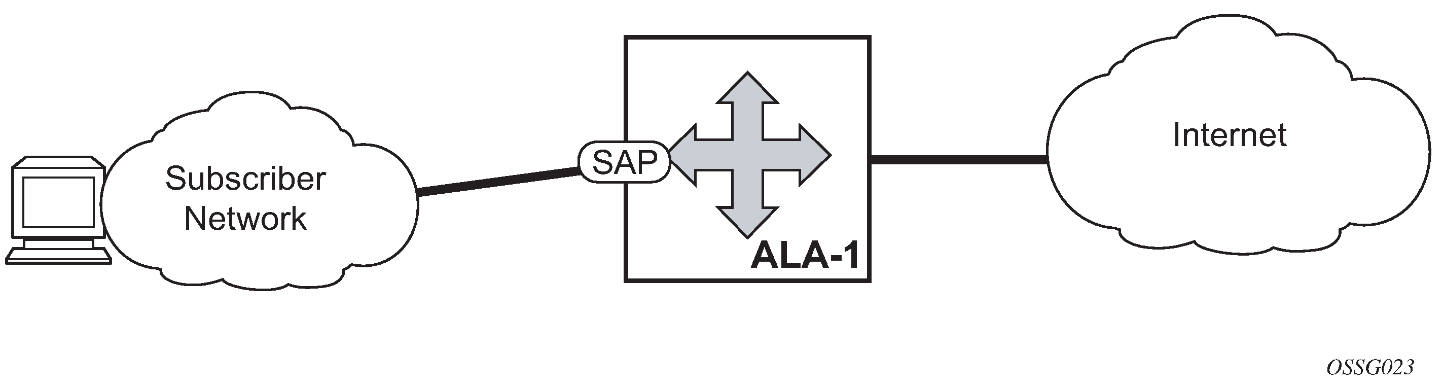
Internet Enhanced Service (IES) is a routed connectivity service where the subscriber communicates with an IP router interface to send and receive Internet traffic. An IES has one or more logical IP routing interfaces each with a SAP which acts as the access point to the subscriber’s network. IES allows customer-facing IP interfaces to participate in the same routing instance used for service network core routing connectivity. IES services require that the IP addressing scheme used by the subscriber be unique between other provider addressing schemes and potentially the entire Internet.
While IES is part of the routing domain, the usable IP address space may be limited. This allows a portion of the service provider address space to be reserved for service IP provisioning, and be administered by a separate but subordinate address authority.
IP interfaces defined within the context of an IES service must have a SAP associated as the uplink access point to the subscriber network. Multiple IES services are created to segregate subscriber-owned IP interfaces.
The IES service provides Internet connectivity. Other features include:
multiple IES services are created to separate customer-owned IP interfaces
more than one IES service can be created for a single customer ID
more than one IP interface can be created within a single IES service ID
All IP interfaces created within an IES service ID belong to the same customer.
These features apply to the 7750 SR and 7450 ESS.
See the 7450 ESS, 7750 SR, and VSR Triple Play Service Delivery Architecture Guide for information about how subscriber group-interfaces function in the Routed Central Office model.
IES features
This section describes the 7450 ESS and 7750 SR service features and any special capabilities or considerations as they relate to IES services.
IP interfaces
IES customer IP interfaces can be configured with most of the same options found on the core IP interfaces. The advanced configuration options supported are:
QoS Policy Propagation Using BGP (QPPB)
VRRP - for IES services with more than one IP interface
Cflowd
Secondary IP addresses
ICMP Options
Configuration options found on core IP interfaces not supported on IES IP interfaces are:
MPLS forwarding
NTP broadcast receipt
QoS Policy Propagation Using BGP
This section discusses QoS Policy Propagation via BGP (QPPB) as it applies to VPRN, IES, and router interfaces. See the IES section and the ‟IP Router Configuration” section in the 7450 ESS, 7750 SR, 7950 XRS, and VSR Router Configuration Guide.
QoS policy propagation using BGP (QPPB) is a feature that allows a route to be installed in the routing table with a forwarding-class and priority so that packets matching the route can receive the associated QoS. The forwarding-class and priority associated with a BGP route are set using BGP import route policies. In the industry, this feature is called QPPB, and even though the feature name refers to BGP specifically. On SR OS, QPPB is supported for BGP (IPv4, IPv6, VPN-IPv4, VPN-IPv6), RIP and static routes.
While SAP ingress and network QoS policies can achieve the same end result as QPPB, the effort involved in creating the QoS policies, keeping them up-to-date, and applying them across many nodes is much greater than with QPPB. This is because of assigning a packet, arriving on a particular IP interface, to a specific forwarding-class and priority/profile, based on the source IP address or destination IP address of the packet. In a typical application of QPPB, a BGP route is advertised with a BGP community attribute that conveys a particular QoS. Routers that receive the advertisement accept the route into their routing table and set the forwarding-class and priority of the route from the community attribute.
QPPB applications
There are two typical applications of QPPB:
-
coordination of QoS policies between different administrative domains
-
traffic differentiation within a single domain, based on route characteristics
Inter-AS coordination of QoS policies
The user of an administrative domain A can use QPPB to signal to a peer administrative domain B that traffic sent to specific prefixes advertised by domain A should receive a particular QoS treatment in domain B. More specifically, an ASBR of domain A can advertise a prefix XYZ to domain B and include a BGP community attribute with the route. The community value implies a particular QoS treatment, as agreed by the two domains (in their peering agreement or service level agreement, for example). When the ASBR and other routers in domain B accept and install the route for XYZ into their routing table, they apply a QoS policy on selected interfaces that classifies traffic toward network XYZ into the QoS class implied by the BGP community value.
QPPB may also be used to request that traffic sourced from specific networks receive appropriate QoS handling in downstream nodes that may span different administrative domains. This can be achieved by advertising the source prefix with a BGP community, as discussed above. However, in this case other approaches are equally valid, such as marking the DSCP or other CoS fields based on source IP address so that downstream domains can take action based on a common understanding of the QoS treatment implied by different DSCP values.
In the above examples, coordination of QoS policies using QPPB could be between a business customer and its IP VPN service provider, or between one service provider and another.
Traffic differentiation based on route characteristics
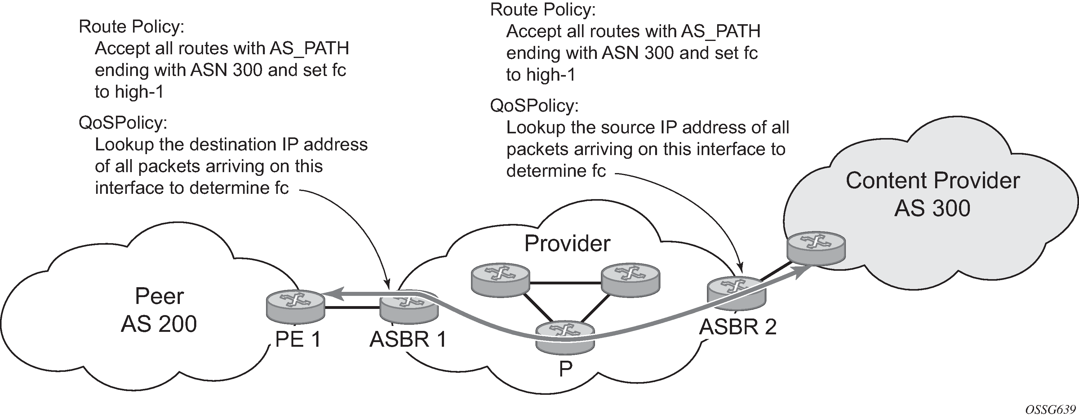
There may be times when a network user wants to provide differentiated service to specific traffic flows within its network, and these traffic flows can be identified with known routes. For example, the user of an ISP network may want to give priority to traffic originating in a particular ASN (the ASN of a content provider offering over-the-top services to the ISP’s customers), following a specific AS_PATH, or destined for a particular next-hop (remaining on-net vs. off-net).
Use of QPPB to differentiate traffic in an ISP network shows an example of an ISP that has an agreement with the content provider managing AS300 to provide traffic sourced and terminating within AS300 with differentiated service appropriate to the content being transported. In this example, we presume that ASBR1 and ASBR2 mark the DSCP of packets terminating and sourced, respectively, in AS300 so that other nodes within the ISP’s network do not need to rely on QPPB to determine the correct forwarding-class to use for the traffic. The DSCP or other CoS markings could be left unchanged in the ISP’s network and QPPB used on every node.
QPPB
There are two main aspects of the QPPB feature:
the ability to associate a forwarding-class and priority with specific routes in the routing table.
the ability to classify an IP packet arriving on a particular IP interface to the forwarding-class and priority associated with the route that best matches the packet.
Associating an FC and priority with a route
Use the following commands to set the forwarding class and optionally the priority associated with routes accepted by a route-policy entry:
- MD-CLI
configure policy-options policy-statement entry action fowarding-class fc configure policy-options policy-statement entry action fowarding-class priority - classic
CLI
configure router policy-options policy-statement entry action fc priority
The following example shows the configuration of the forwarding class and priority.
MD-CLI
[ex:/configure policy-options]
A:admin@node-2# info
    community "gold" {
        member "300:100" { }
    }
    policy-statement "qppb_policy" {
        entry 10 {
            from {
                community {
                    name "gold"
                }
                protocol {
                    name [bgp]
                }
            }
            action {
                action-type accept
                forwarding-class {
                    fc h1
                    priority high
                }
            }
        }
    }
classic CLI
A:node-2>config>router>policy-options# info
----------------------------------------------
            community "gold"
                members "300:100"
            exit
            policy-statement "qppb_policy"
                entry 10
                    from
                        protocol bgp
                        community "gold"
                    exit
                    action accept
                        fc h1 priority high
                    exit
                exit
            exit
----------------------------------------------
The fc command is supported with all existing from and to match conditions in a route policy entry and with any action other than reject, it is supported with the next-entry, next-policy, and accept actions. If a next-entry or next-policy action results in multiple matching entries, the last entry with a QPPB action determines the forwarding class and priority.
A route policy that includes the fc command in one or more entries can be used in any import or export policy but the fc command has no effect except in the following types of policies:
-
MD-CLI
-
VRF import policies
configure service vprn bgp-evpn mpls vrf-import configure service vprn bgp-ipvpn mpls vrf-import configure service vprn bgp-ipvpn srv6 vrf-import configure service vprn mvpn vrf-import -
BGP import policies:
configure router bgp import configure router bgp group import configure router bgp neighbor import configure service vprn bgp import configure service vprn bgp group import configure service vprn bgp neighbor import -
RIP import policies
configure router rip import-policy
configure router rip group import-policy
configure router rip group neighbor import-policy
configure service vprn rip import-policy
configure service vprn rip group import-policy
configure service vprn rip group neighbor import-policy
-
-
classic CLI
-
VRF import policies
configure service vprn bgp-evpn mpls vrf-import configure service vprn bgp-ipvpn mpls vrf-import configure service vprn bgp-ipvpn segment-routing-v6 vrf-import configure service vprn mvpn vrf-import -
BGP import policies
configure router bgp import configure router bgp group import configure router bgp group neighbor import configure service vprn bgp import configure service vprn bgp group import configure service vprn bgp group neighbor import -
RIP import policies
configure router rip import
configure router rip group import
configure router rip group neighbor import
configure service vprn rip import
configure service vprn rip group import
configure service vprn rip group neighbor import
-
As evident from above, QPPB route policies support routes learned from RIP and BGP neighbors of a VPRN as well as for routes learned from RIP and BGP neighbors of the base/global routing instance.
QPPB is supported for BGP routes belonging to any of the address families listed below:
-
IPv4 (AFI=1, SAFI=1)
-
IPv6 (AFI=2, SAFI=1)
-
VPN-IPv4 (AFI=1, SAFI=128)
-
VPN-IPv6 (AFI=2, SAFI=128)
A VPN-IP route may match both a VRF import policy entry and a BGP import policy entry (if vpn-apply-import is configured in the base router BGP instance). In this case the VRF import policy is applied first and then the BGP import policy, so the QPPB QoS is based on the BGP import policy entry.
This feature also introduces the ability to associate a forwarding class and optionally priority with IPv4 and IPv6 static routes. This is achieved by specifying the forwarding class within the static route entry using the next-hop or indirect commands.
Priority is optional when specifying the forwarding class of a static route, but when configured it can only be deleted and returned to unspecified by deleting the entire static route.
Displaying QoS information associated with routes
Use the following commands to show the forwarding-class and priority associated with the displayed routes.
show router route-table
show router fib
show router bgp routes
show router rip database
show router static-route
Use the following command to show an additional line per route entry that displays the forwarding class and priority of the route. When the qos command option is specified, the output includes an additional line per route entry that displays the forwarding class and priority of the route. If a route has no forwarding class and priority information, the third line is blank.
show router route-table 10.1.5.0/24 qos===============================================================================
Route Table (Router: Base)
===============================================================================
Dest Prefix Type Proto Age Pref
Next Hop[Interface Name] Metric
QoS
-------------------------------------------------------------------------------
10.1.5.0/24 Remote BGP 15h32m52s 0
PE1_to_PE2 0
h1, high
-------------------------------------------------------------------------------
No. of Routes: 1
===============================================================================Enabling QPPB on an IP interface
To enable QoS classification of ingress IP packets on an interface based on the QoS information associated with the routes that best match the packets, the qos-route-lookup command necessary in the configuration of the IP interface. The qos-route-lookup command has command options to indicate whether the QoS result is based on lookup of the source or destination IP address in every packet. There are separate qos-route-lookup commands for the IPv4 and IPv6 packets on an interface, which allows QPPB to enabled for IPv4 only, IPv6 only, or both IPv4 and IPv6. The current QPPB based on a source IP address is not supported for IPv6 packets nor is it supported for ingress subscriber management traffic on a group interface.
The qos-route-lookup command is supported on the following types of IP interfaces:
-
Base router network interfaces
- MD-CLI
configure router interface ipv4 configure router interface ipv6 - classic
CLI
configure router interface ipv6
configure router interface
- MD-CLI
-
VPRN SAP and spoke SDP interfaces
- MD-CLI
configure service vprn interface ipv4 configure service vprn interface ipv6 - classic
CLI
configure service vprn interface
configure service vprn interface ipv6
- MD-CLI
-
VPRN group-interfaces
- MD-CLI
configure service vprn subscriber-interface group-interface ipv4 configure service vprn subscriber-interface group-interface ipv6 - classic
CLI
configure service vprn subscriber-interface group-interface
configure service vprn subscriber-interface group-interface ipv6
- MD-CLI
-
IES SAP and spoke SDP interfaces
- MD-CLI
configure service ies interface ipv4 configure service ies interface ipv6 - classic
CLI
configure service ies interface
configure service ies interface ipv6
- MD-CLI
-
IES group-interfaces
- MD-CLI
configure service ies subscriber-interface group-interface ipv4 configure service ies subscriber-interface group-interface ipv6 - classic
CLI
configure service ies subscriber-interface group-interface
configure service ies subscriber-interface group-interface ipv6
- MD-CLI
- the qos-route-lookup command with the destination command option is applied to an IP interface
- the destination address of an incoming IP packet matches a route with QoS information
If the destination address of the incoming packet matches a route with no QoS information the FC and priority of the packet remain as determined by the SAP ingress or network QoS policy.
- the qos-route-lookup command with the source command option is applied to an IP interface
- the source address of an incoming IP packet matches a route with QoS information the packet is classified to the FC and priority associated with that route
If the source address of the incoming packet matches a route with no QoS information the FC and priority of the packet remain as determined by the SAP ingress or network QoS policy.
Currently, QPPB is not supported for ingress MPLS traffic on network interfaces or on CsC-PE or CsC-CE interfaces under the following context.
configure service vprn network-interfaceQPPB when next hops are resolved by QPPB routes
In some circumstances (IP VPN inter-AS model C, Carrier Supporting Carrier, indirect static routes, and so on) an IPv4 or IPv6 packet may arrive on a QPPB-enabled interface and match a route A1 whose next-hop N1 is resolved by a route A2 with next-hop N2 and perhaps N2 is resolved by a route A3 with next-hop N3, and so on. The QPPB result is based only on the forwarding-class and priority of route A1. If A1 does not have a forwarding-class and priority association then the QoS classification is not based on QPPB, even if routes A2, A3, and so on. have forwarding-class and priority associations.
QPPB and multiple paths to a destination
When ECMP is enabled some routes may have multiple equal-cost next-hops in the forwarding table. When an IP packet matches such a route the next-hop selection is typically based on a hash algorithm that tries to load balance traffic across all the next-hops while keeping all packets of a specific flow on the same path. The QPPB configuration model described in Associating an FC and priority with a route allows different QoS information to be associated with the different ECMP next-hops of a route. The forwarding class (FC) and priority of a packet matching an ECMP route is based on the particular next-hop used to forward the packet.
When BGP fast reroute [1] is enabled some BGP routes may have a backup next-hop in the forwarding table in addition to the one or more primary next-hops representing the equal-cost best paths allowed by the ECMP/multipath configuration. When an IP packet matches such a route a reachable primary next-hop is selected (based on the hash result) but if all the primary next-hops are unreachable then the backup next-hop is used. The QPPB configuration model described in Associating an FC and priority with a route allows the forwarding-class and priority associated with the backup path to be different from the QoS characteristics of the equal-cost best paths. The forwarding class and priority of a packet forwarded on the backup path is based on the FC and priority of the backup route.
QPPB and policy-based routing
When an IPv4 or IPv6 packet with destination address X arrives on an interface with both QPPB and policy-based-routing enabled:
There is no QPPB classification if the IP filter action redirects the packet to a directly connected interface, even if X is matched by a route with a forwarding-class and priority
QPPB classification is based on the forwarding-class and priority of the route matching IP address Y if the IP filter action redirects the packet to the indirect next-hop IP address Y, even if X is matched by a route with a forwarding-class and priority
QPPB and GRT lookup
Source-address based QPPB is not supported on any SAP or spoke SDP interface of a VPRN configured with the following command:
- MD-CLI
configure service vprn grt-leaking grt-lookup - classic
CLI
configure service vprn grt-lookup
QPPB interaction with SAP ingress QoS policy
When QPPB is enabled on a SAP IP interface the forwarding class of a packet may change from fc1, the original FC determined by the SAP ingress QoS policy to fc2, the new fc determined by QPPB. In the ingress datapath SAP ingress QoS policies are applied in the first P chip and route lookup/QPPB occurs in the second P chip. This has the implications listed below:
-
Ingress remarking (based on profile state) is always based on the original fc (fc1) and sub-class (if defined)
-
The profile state of a SAP ingress packet that matches a QPPB route depends on the configuration of fc2 only. If the de-1-out-profile flag is enabled in fc2 and fc2 is not mapped to a priority mode queue, then the packet is marked out of profile if its DE bit = 1. If the profile state of fc2 is explicitly configured (in or out) and fc2 is not mapped to a priority mode queue then the packet is assigned this profile state. In both cases, there is no consideration of whether fc1 was mapped to a priority mode queue.
-
The priority of a SAP ingress packet that matches a QPPB route depends on several factors. If the de-1-out-profile flag is enabled in fc2 and the DE bit is set in the packet then priority is low regardless of the QPPB priority or fc2 mapping to profile mode queue, priority mode queue or policer. If fc2 is associated with a profile mode queue then the packet priority is based on the explicitly configured profile state of fc2 (in profile = high, out profile = low, undefined = high), regardless of the QPPB priority or fc1 configuration. If fc2 is associated with a priority mode queue or policer then the packet priority is based on QPPB (unless DE=1), but if no priority information is associated with the route then the packet priority is based on the configuration of fc1 (if fc1 mapped to a priority mode queue then it is based on DSCP/IP prec/802.1p and if fc1 mapped to a profile mode queue then it is based on the profile state of fc1).
QPPB interactions with SAP ingress QoS summarizes the interactions.
|
Original FC object mapping |
New FC object mapping |
Profile |
Priority (drop preference) |
DE=1 override |
In/out of profile marking |
|---|---|---|---|---|---|
|
Profile mode queue |
Profile mode queue |
From new base FC unless overridden by DE=1 |
From QPPB, unless packet is marked in or out of profile in which case follows profile. Default is high priority. |
From new base FC |
From original FC and sub-class |
|
Priority mode queue |
Priority mode queue |
Ignored |
If DE=1 override then low otherwise from QPPB. If no DEI or QPPB overrides then from original dot1p/exp/DSCP mapping or policy default. |
From new base FC |
From original FC and sub-class |
|
Policer |
Policer |
From new base FC unless overridden by DE=1 |
If DE=1 override then low otherwise from QPPB. If no DEI or QPPB overrides then from original dot1p/exp/DSCP mapping or policy default. |
From new base FC |
From original FC and sub-class |
|
Priority mode queue |
Policer |
From new base FC unless overridden by DE=1 |
If DE=1 override then low otherwise from QPPB. If no DEI or QPPB overrides then from original dot1p/exp/DSCP mapping or policy default. |
From new base FC |
From original FC and sub-class |
|
Policer |
Priority mode queue |
Ignored |
If DE=1 override then low otherwise from QPPB. If no DEI or QPPB overrides then from original dot1p/exp/DSCP mapping or policy default. |
From new base FC |
From original FC and sub-class |
|
Profile mode queue |
Priority mode queue |
Ignored |
If DE=1 override then low otherwise from QPPB. If no DEI or QPPB overrides then follows original FC’s profile mode rules. |
From new base FC |
From original FC and sub-class |
|
Priority mode queue |
Profile mode queue |
From new base FC unless overridden by DE=1 |
From QPPB, unless packet is marked in or out of profile in which case follows profile. Default is high priority. |
From new base FC |
From original FC and sub-class |
|
Profile mode queue |
Policer |
From new base FC unless overridden by DE=1 |
If DE=1 override, then low otherwise from QPPB. If no DEI or QPPB overrides, then follows original FC’s profile mode rules. |
From new base FC |
From original FC and sub-class |
|
Policer |
Profile mode queue |
From new base FC unless overridden by DE=1 |
From QPPB, unless packet is marked in or out of profile in which case follows profile. Default is high priority. |
From new base FC |
From original FC and sub-class |
Object grouping and state monitoring
This feature introduces a generic operational group object which associates different service endpoints (pseudowires and SAPs) located in the same or in different service instances. The operational group status is derived from the status of the individual components using specific rules specific to the application using the concept. A number of other service entities, the monitoring objects, can be configured to monitor the operational group status and to perform specific actions as a result of status transitions. For example, if the operational group goes down, the monitoring objects are brought down.
IES IP interface applicability
This concept is used by an IPv4 IES interface to affect the operational state of the IP interface monitoring the operational group. Individual SAP and spoke SDPs are supported as monitoring objects.
The following rules apply:
An object can only belong to one group at a time.
An object that is part of a group cannot monitor the status of a group.
An object that monitors the status of a group cannot be part of a group.
An operational group may contain any combination of member types, SAP, or spoke SDPs.
An operational group may contain members from different VPLS service instances.
Objects from different services may monitor the operational group.
There are two steps involved in enabling the functionality:
Identify a set of objects whose forwarding state should be considered as a whole group, then group them under an operational group using the oper-group command.
Associate the IP interface to the operational group using the monitor-oper-group command.
The status of the operational group is dictated by the status of one or more members according to the following rules:
The operational group goes down if all the objects in the operational group go down. The operational group comes up if at least one component is up.
An object in the group is considered down if it is not forwarding traffic in at least one direction. That could be because the operational state is down or the direction is blocked through some validation mechanism.
If a group is configured but no members are specified yet, then its status is considered up.
As soon as the first object is configured the status of the operational group is dictated by the status of the provisioned members.
The following configuration shows the operational group g1, the VPLS SAP that is mapped to it and the IP interfaces in IES service 2001 monitoring the operational group g1. This example uses an R-VPLS context.
Operational group g1 has a single SAP (1/1/1:2001) mapped to it and the IP interfaces in the IES service 2001 derive its state from the state of operational group g1.
MD-CLI
In the MD-CLI, the VPLS instance includes the name v1. The IES interface links to the VPLS using the vpls command option.
[ex:/configure service]
A:admin@node-2# info
    oper-group "g1" {
    }
    ies "2001" {
        customer "1"
        interface "i2001" {
            monitor-oper-group "g1"
            vpls "v1" {
            }
            ipv4 {
                primary {
                    address 192.168.1.1
                    prefix-length 24
                }
            }
        }
    }
    vpls "v1" {
        admin-state enable
        service-id 1
        customer "1"
        routed-vpls {
        }
        stp {
            admin-state disable
        }
        sap 1/1/1:2001 {
            oper-group "g1"
            eth-cfm {
            mep md-admin-name "1" ma-admin-name "1" mep-id 1 {
            }
        }
        sap 1/1/2:2001 {
        }
        sap 1/1/3:2001 {
        }
    }
classic CLI
In the classic CLI, the VPLS instance includes the allow-ip-int-bind and the name v1. The IES interface links to the VPLS using the vpls command option.
A:node-2>config>service# info
----------------------------------------------
        oper-group "g1" create
        exit
        vpls 1 name "v1" customer 1 create
            allow-ip-int-bind
            exit
            stp
                shutdown
            exit
            sap 1/1/1:2001 create
                oper-group "g1"
                eth-cfm
                    mep 1 domain 1 association 1 direction down
                    ccm-enable
                no shutdown
            exit
            sap 1/1/2:2001 create
                no shutdown
            exit
            sap 1/1/3:2001 create
                no shutdown
            exit
            no shutdown
        exit
        ies 2001 name "2001" customer 1 create
            shutdown
            interface "i2001" create
                monitor-oper-group "g1"
                address 192.168.1.1/24
                vpls "v1"
                exit
            exit
        exit
Subscriber interfaces
Subscriber interfaces are composed of a combination of two key technologies, subscriber interfaces and group interfaces. While the subscriber interface defines the subscriber subnets, the group interfaces are responsible for aggregating the SAPs. Subscriber interfaces apply to the 7450 ESS and 7750 SR only.
subscriber interface
This is an interface that allows the sharing of a subnet among one or many group interfaces in the routed CO model.
group interface
This interface aggregates multiple SAPs on the same port.
redundant interfaces
This is a special spoke-terminated Layer 3 interface. It is used in a Layer 3 routed CO dual-homing configuration to shunt downstream (network to subscriber) to the active node for a specific subscriber. Redundant interfaces apply to the 7750 SR only.
IPv6 ESM
All IPv6 Enhanced Subscriber Management (ESM) services require either Routed CO (IES), or Routed CO for VPRN as a supporting service construct. Because of the complexities of the IPv6 link-model, there is currently no support for IPv6 ESM in a VPLS. There is also currently no support for IPv6 in combination with Basic Subscriber Management (BSM). This feature applies to the 7450 ESS and 7750 SR only.
RADIUS accounting
In the 7750 SR OS, the accounting paradigm is based on SLA profile instances, yet this is at odds with traditional RADIUS authentication and accounting which is host-centric. In previous OS releases, it was possible to have many hosts sharing a common SLA profile instance; and therefore, accounting and QoS command options. Complications would arise with RADIUS accounting because Accounting-Start and Accounting-Stop are a function of SLA profile instance and not the hosts – this meant that some host-specific command options (like Framed-Ip-Address) would not be consistently included in RADIUS accounting.
Dual-stack subscribers are now two different hosts sharing a single SLA profile instance. A RADIUS accounting mode supports multiple-host environments. Use the following command to allow this configurable accounting mode.
configure subscriber-mgmt radius-accounting-policy host-accountingHost accounting disabled
When host accounting is disabled, accounting behavior is as follows:
-
A RADIUS accounting start message is sent when the SLA profile instance is created. It contains accounting (octets/packets) and the Framed-Ip-Address of the host which caused the SLA profile instance to be created.
-
Additional hosts may bind to the SLA profile instance at any time, but no additional accounting messages are sent during these events.
-
If the original host disconnects, future accounting messages use an IP address of one of the remaining hosts.
-
When the final host associated with an SLA profile instance disconnects, an accounting stop message is sent.
Host accounting enabled
When host accounting is enabled, additional RADIUS accounting messages are created for host activity in addition to messages for common queue accounting. The behavior is as follows:
-
A RADIUS accounting start message is sent each time a host is authenticated. It contains the Framed-Ip-Address among other things. It does not contain any octet or packet counts.
-
A RADIUS accounting start message is sent each time a SLA profile instance is created.
-
Whenever a host disconnects a RADIUS, accounting stop message is sent for that host.
-
If all host associated with an SLA profile instance disconnect, a RADIUS accounting stop message is sent for that instance.
This behavior means specific AVP may be in either host, sla-profile instance, or both accounting records. See the following table for more information about RADIUS accounting.
Interim-Acct records are not sent for hosts, only the start- and stop-accounting messages.
|
RADIUS accounting AVP |
Host accounting |
SLA-profile accounting |
|---|---|---|
|
User-Name |
Yes |
— |
|
NAS-Identifier |
Yes |
Yes |
|
NAS-IP-Address |
Yes |
Yes |
|
Nas-Port-Id |
Yes |
— |
|
Nas-Port |
Yes |
— |
|
Nas-Port-Type |
Yes |
— |
|
Service-Type |
Yes |
— |
|
Framed-Protocol |
Yes |
— |
|
Framed-Ip-Address |
Yes |
— |
|
Framed-Ip-Netmask |
Yes |
— |
|
Framed-Route |
Yes |
— |
|
Class |
Yes |
— |
|
Session-Timeout |
Yes |
Yes |
|
Circuit-Id VSA |
Yes |
— |
|
Called-Station-Id |
Yes |
— |
|
Calling-Station-Id |
Yes |
— |
|
MAC-Addr VSA |
Yes |
— |
|
Remote-Id VSA |
Yes |
— |
|
Acct-Input-Octets |
— |
Yes |
|
Acct-Output-Octets |
— |
Yes |
|
Acct-Input-Gigawords |
— |
Yes |
|
Acct-Output-Gigawords |
— |
Yes |
|
Acct-Session-Id |
Yes |
Yes |
|
Acct-Session-Time |
Yes |
Yes |
|
Acct-Input-Packets |
— |
Yes |
|
Acct-Output-Packets |
— |
Yes |
|
Agent-Circuit-Id |
Yes |
— |
|
Agent-Remote-Id |
Yes |
— |
|
Actual-Data-Rate-Upstream |
Yes |
— |
|
Actual-Data-Rate-Downstream |
Yes |
— |
|
Access-Loop-Encapsulation |
Yes |
— |
|
Alc-Accounting |
— |
Yes |
|
Alc-Subscriber-Id |
Yes |
Yes |
|
Alc-Subscriber-Profile-String |
Yes |
Yes |
|
Alc-Sla-Profile-String |
Yes |
Yes |
RADIUS connectivity
SR OS supports IPv4/IPv6 RADIUS connectivity for dot1x host authentication. Use the commands in following context to support the IPv4 connectivity in legacy configurations:
- MD-CLI
configure system security aaa remote-servers radius - classic
CLI
configure system security radius
Use the following command to support IPv4/IPv6 connectivity through the common RADIUS backend server:
- MD-CLI
configure router radius server - classic
CLI
configure router radius-server
RADIUS connectivity on VPRN or GRT
The RADIUS connectivity used for dot1x authentication is reachable through the following services:
GRT
VPRN
R-VPLS (VPRN, IES)
For R-VPLS, the port terminating the dot1x is a VPLS/EVPN SAP, but the RADIUS server is reachable through the same R-VPLS L3 Service, that is the VPRN or IES that the R-VPLS is connected to.
RADIUS support for IPv6 server connectivity
The current RADIUS profile used for dot1x authentication does not support IPv6 connectivity under the following context.
configure system security dot1x radius-policyUse the commands in the following contexts to configure the system-wide RADIUS server, which supports IPv6 connectivity for dot1x host authentication:
- MD-CLI
configure router radius server configure service vprn radius server - classic
CLI
configure router radius-server
configure service vprn radius-server
Common backend RADIUS server support
The dot1x RADIUS servers use the common backend RADIUS server. Use the commands in the following contexts to support the common backend RADIUS server, which can support both IPv4 and IPv6 RADIUS connectivity:
- MD-CLI
configure router radius server configure service vprn radius server - classic
CLI
configure router radius-server
configure service vprn radius-server
Use the commands in the following context to place these RADIUS servers under a RADIUS policy:
- MD-CLI
configure aaa radius server-policy - classic
CLI
configure aaa radius-server-policy
- MD-CLI
7450 ESS, 7750 SR, 7950 XRS, and VSR MD-CLI Command Reference Guide
- classic CLI
7450 ESS, 7750 SR, 7950 XRS, and VSR Classic CLI Command Reference Guide
The RADIUS policy can be assigned to a dot1x through RADIUS server policy under the dot1x configuration.
RADIUS Base router configuration (MD-CLI)
[ex:/configure router "Base" radius]
A:admin@node-2# info
    server "1" {
        address 10.10.0.1
        secret "test1 hash2"
    }
RADIUS Base router configuration (classic CLI)
A:node-2>config>router>radius-server# info
----------------------------------------------
            server "1" address 10.10.0.1 secret "test1" hash2 create
            exit
----------------------------------------------
RADIUS VPRN configuration (MD-CLI)
[ex:/configure service vprn "101" radius]
A:admin@node-2# info
    server "1" {
        address 10.10.10.1
        secret "test1 hash2"
    }
RADIUS VPRN configuration (classic CLI)
A:cses-V27>config>service>vprn>radius-server$ info
----------------------------------------------
                server "1" address 10.10.10.1 secret "test1" hash2 create
                exit
----------------------------------------------
After a server is configured, you can create a RADIUS policy from the configured servers. For server redundancy, multiple servers can exist for a policy.
Multiple RADIUS servers under one policy configuration (MD-CLI)
[ex:/configure aaa]
A:admin@node-2# info
    radius {
        server-policy "test" {
            servers {
                router-instance "60"
                server 1 {
                    server-name "test"
                }
                server 2 {
                    server-name "test2"
                }
            }
        }
    }
Multiple RADIUS servers under one policy configuration (classic CLI)
A:node-2>config>aaa# info
----------------------------------------------
        radius-server-policy "test" create
            servers
                router 60
                server 1 name "test"
                server 2 name "test2"
            exit
        exit
RADIUS server policy with a port dot1x configuration (MD-CLI)
[ex:/configure port 1/1/c1/1]
A:admin@node-2# info
    ethernet {
        dot1x {
            radius-server-policy "test"
        }
    }
RADIUS server policy with a port dot1x configuration (classic CLI)
A:node-2>config>port# info
----------------------------------------------
        shutdown
        ethernet
            dot1x
                radius-server-policy "test"
            exit
        exit
----------------------------------------------
Authentication and accounting RADIUS server
The user can configure separate authentication and accounting RADIUS servers for dot1x. Two separate RADIUS policies must be set and assigned correctly to the dot1x RADIUS server policy for authentication and accounting.
Accounting considerations for per-host configurations
When the dot1x is configured as per-host, accounting is disabled and a zero (0) value is provided for the following attributes:
Acct-Input-Octets (RFC 2866)
Acct-Output-Octets (RFC 2866)
Acct-Input-Packets (RFC 2866)
Acct-Output-Packets (RFC 2866)
Acct-Input-Gigawords (RFC 2869)
Acct-Output-Gigawords (RFC 2869)
SAPs
Encapsulations
The following SAP encapsulations are supported on the IES services:
-
Ethernet null
-
Ethernet dot1q
Pseudowire SAPs
This feature allows customers of an IES, VPRN, or Epipe VLL service and connected to an Ethernet SAP on an Access PE to be backhauled through an Ethernet aggregation network using MPLS pseudowires terminating directly on a converged PE hosting the IES, VPRN, or Epipe VLL service. If Enhanced Subscriber Management over PW is also used, then the converged PE may also act as a BNG. This service is different from VLL Spoke-SDP termination on an IES or VPRN because access QoS policies can be applied directly at a centralized PE hosting the IES or VPRN instance. This feature uses the same concepts of pseudowire ports and pseudowire SAPs that are used for ESM over MPLS pseudowires, described in the 7450 ESS, 7750 SR, and VSR Triple Play Service Delivery Architecture Guide.
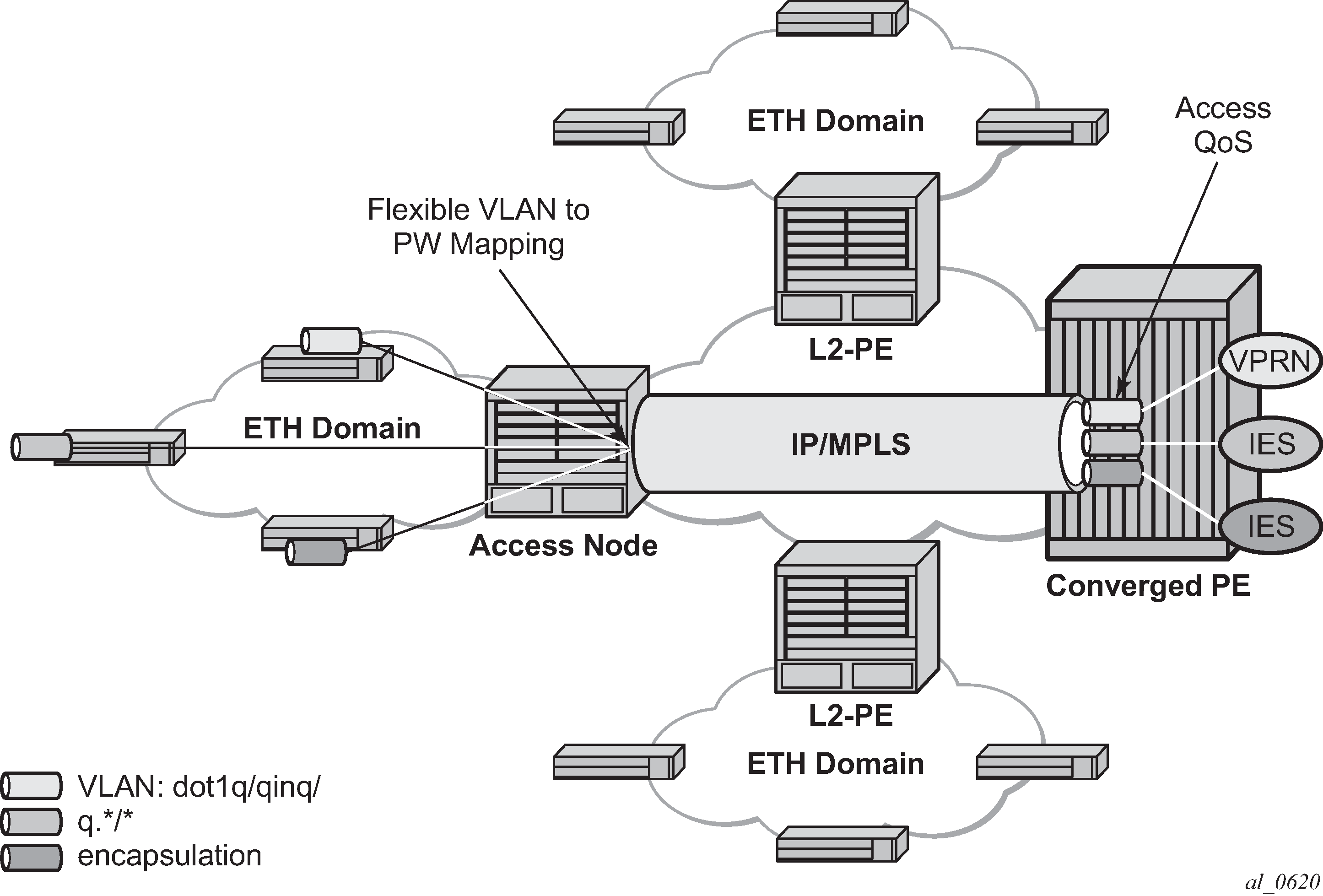
The MPLS pseudowire originates from the first hop aggregation PE (referred to as access PE) upstream of the Access-Node (or directly from a multi-service AN), and terminates on the converged PE. Multiple customers from a specific access-port on the Access-PE can be backhauled over a single MPLS pseudowire toward the converged PE. This capability allows the network to scale and does not require an MPLS pseudowire per customer between the Access-PE and the converged PE. The access-port on the Access-PE can be dot1q, q-in-q or NULL encapsulated. The converged PE terminates the MPLS pseudowire, decapsulates the received frames, and provides access QoS functions including HQoS, without requiring an internal or external loopback. Each MPLS pseudowire is represented on the BNG as a ‟PW-port” for which SAPs are created. These SAPs are termed ‟PW SAPs”, and must be statically configured on IES or VPRN interfaces or under the VLL service (unlike the ESM case where a capture SAP can be configured). The underlying Ethernet port must be in hybrid mode. Pseudowire SAPs are supported on Ethernet MDAs.
Network architecture using pseudowire SAPs illustrates the architecture of an aggregation network that uses pseudowire SAPs.
Encapsulation
The packet is encapsulated on an Ethernet pseudowire, which is associated with a pseudowire port on the converged PE, and a spoke SDP on the access PE. The SDP could use an LDP LSP, RSVP LSP, segment routed tunnel, BGP RFC 8277 tunnel, or LDP over RSVP tunnel. Hash labels are not supported. The SDP may be bound to a port or a LAG, although shaping Vports for pseudowire ports on LAGs in distributed mode is not supported. If an SDP is rerouted, then the corresponding pseudowire ports are brought operationally down. Pseudowire ports are associated with an SDP by configuration.
Pseudowire SAP configuration
The following prerequisites are required at the access PE:
-
Configure an Epipe VLL service.
-
Configure a NULL, 1q or QinQ SAP on the Epipe service.
The steps in this procedure are used to configure a pseudowire SAP on the IES or VPRN service at the Layer 3 PE.
The PW SAP may be mated to an Ethernet SAP or an Ethernet spoke SDP in the Epipe VLL service. A PW SAP may also form a part of an Epipe service that contains a PBB tunnel, as shown in the following example.
Example: PW SAP in an Epipe service with a PBB configuration (MD-CLI)
[ex:/configure service]
A:admin@node-2# info
...
    epipe "access-vc-100" {
        admin-state enable
        service-id 300
        customer "1"
        pbb {
            tunnel {
                backbone-vpls-service-name "30123"
                isid 100
                backbone-dest-mac 00:00:5e:00:53:02
            }
        }
        sap pw-8:10.20 {
                admin-state enable
            }
        sap lag-3:25.100 {
                admin-state enable
            }
    }
Example: PW SAP in an Epipe service with a PBB configuration (classic CLI)
A:node-2>config>service# info
----------------------------------------------
 ...
        epipe 300 name "access-vc-100" customer 1 create
            pbb
                tunnel 30123 backbone-dest-mac 00:00:5e:00:53:02 isid 100
            exit
            sap lag-3:25.100 create
                no shutdown
            exit
            sap pw-8:10.20 create
                no shutdown
            no shutdown
            exit
exit-
Define a pseudowire port.
Pseudowire port configuration (MD-CLI)
[ex:/configure]
A:admin@node-2# info
...
    pw-port 1 {
    }
    pw-port 2 {
    }
Pseudowire port configuration (classic CLI)A:node-2>config# admin display-config #-------------------------------------------------- echo "PW-Port Configuration" #-------------------------------------------------- pw-port 1 create exit pw-port 2 create exit #-------------------------------------------------- -
Bind a physical port or LAG, in hybrid mode, with the pseudowire port.
Binding a LAG with a PW port (MD-CLI)
[ex:/configure]
A:admin@node-2# info
...
    pw-port 1 {
        encap-type qinq
        sdp 1 {
            admin-state enable
            vc-id 1
        }
    }
    pw-port 2 {
        encap-type qinq
        sdp 1 {
            admin-state enable
            vc-id 2
        }
    }

[ex:/configure service]
A:admin@node-2# info
    customer "1" {
        description "Default customer"
        multi-service-site "abc" {
            assignment {
                port pw-1
            }
            egress {
                policer-control-policy "abc"
            }
        }
    }
    sdp 1 {
        admin-state enable
        delivery-type mpls
        path-mtu 1514
        ldp true
        keep-alive {
            admin-state disable
        }
        far-end {
            ip-address 10.1.1.2
        }
        pw-port {
            binding-port lag-1
        }
    }
Binding a LAG with a PW port (classic CLI)A:node-2>config>service# info ---------------------------------------------- sdp 1 mpls create far-end 10.1.1.2 ldp path-mtu 1514 keep-alive shutdown exit binding port lag-1 pw-port 1 vc-id 1 create no shutdown exit pw-port 2 vc-id 2 create no shutdown exit exit no shutdown exit ... customer 1 name "1" create multi-service-site "abc" create assignment port pw-1 egress policer-control-policy "abc" exit exit description "Default customer" exit -
Depending on whether the PW SAP is on an IES, VPRN, or an Epipe VLL, perform
one of the following steps:
- For a PW SAP on an IES/VPRN, configure a SAP on the IES or VPRN
interface, with a SAP ID that uses the form
pw-id.
Example: PW SAP on an IES interface configuration (MD-CLI)
[ex:/configure service]
A:admin@node-2# info
...
    ies "1" {
        admin-state enable
        customer "1"
        interface "ies if" {
            mac 00:00:00:00:00:ff
            sap pw-1:1 {
            }
            ipv4 {
                primary {
                    address 192.168.1.1
                    prefix-length 24
                }
                neighbor-discovery {
                    static-neighbor 192.168.1.2 {
                        mac-address 00:00:00:00:00:aa
                    }
                }
            }
        }
    }
Example: PW SAP on an IES interface configuration (classic CLI)
A:node-2>config>service# info ---------------------------------------------- ... ies 1 name "1" customer 1 create interface "ies if" create address 192.168.1.1/24 mac 00:00:00:00:00:ff static-arp 192.168.1.2 00:00:00:00:00:aa sap pw-1:1 create exit exit no shutdown exit - For a PW SAP on an Epipe VLL, configure a SAP on the service, with a SAP
ID that uses the form
pw-id.
Example: PW SAP on an Epipe configuration (MD-CLI)
[ex:/configure service]
A:admin@node-2# info
...
    epipe "1" {
        admin-state enable
        customer "1"
        sap pw-1:1 {
            admin-state enable
        }
    }
Example: PW SAP on an Epipe configuration (classic CLI)
A:node-2>config>service# info
----------------------------------------------
...
        epipe 1 name "1" customer 1 create
            sap pw-1:1 create
                no shutdown
            exit
            no shutdown
        exit
- For a PW SAP on an IES/VPRN, configure a SAP on the IES or VPRN
interface, with a SAP ID that uses the form
pw-id.
QoS for pseudowire ports and pseudowire SAPs
Pseudowire SAPs support the QoS models allowed for regular VLL, IES or VPRN SAPs. These include:
Per-service HQoS
Note: This allows shaping of the total traffic per access node (and total traffic per class per AN), assuming one pseudowire per AN from the A-PE.SAP QoS support as available on the IOM3-XP, including
- H-QoS (service scheduler child to port scheduler parent)
-
SAP queues attached to H-QoS scheduler by ‛parent’ statement
-
Scheduler attached to Port Scheduler by ‛port-parent’ statement
-
-
Direct service queue to port scheduler mapping
-
Aggregate-rate-limit
-
Support for the redirection of SAP egress queues to an access queue group instance. It is possible to redirect SAP queues of a pseudowire SAP using the SAP based redirection for the IOM with Ethernet MDA, and policy based redirection for the IOM with Ethernet MDA, as applicable.
- H-QoS (service scheduler child to port scheduler parent)
Policing and H-POL
Shaping and bandwidth control
Pseudowire SAPs can be shaped on egress by a Vport on a physical port. The pseudowire SAP egress cannot explicitly declare which Vport to use, but they inherit the Vport used by the PW port egress shaping.
The intermediate destination identifier, used for ESM on MPLS pseudowires, is not applicable to VLL, IES, and VPRN pseudowire SAPs.
If a pseudowire port is configured on a LAG, Vport shaping is only supported if the LAG is in link mode.
Per-access node shaping is configured as follows:
Configure a Vport per AN under the port (or LAG) to which the SDP corresponding to the pseudowire SAP is bound. Use the rate command option in the following context to configure the Vport with an aggregate rate-limit:
- MD-CLI
configure port ethernet access egress virtual-port aggregate-rate - classic
CLI
configure port ethernet access egress vport agg-rate-limit
- MD-CLI
Explicitly assign (by static configuration) a pseudowire port to a Vport. For limiting the total traffic to an AN, all pseudowire ports for an AN-port would refer to the same Vport.
For bandwidth control per pseudowire, the following configuration steps are used:
Create multiple Vports under the port to which SDP is bound. Each Vport can be configured with an aggregate rate limit, a scheduler, or a port scheduler.
Assign each pseudowire to an AN to a unique Vport shaper (regular IOM/MDA).
To configure the aggregate rate limit or port scheduler under a Vport, PW SAP queues and schedulers must be configured with the port-parent command.
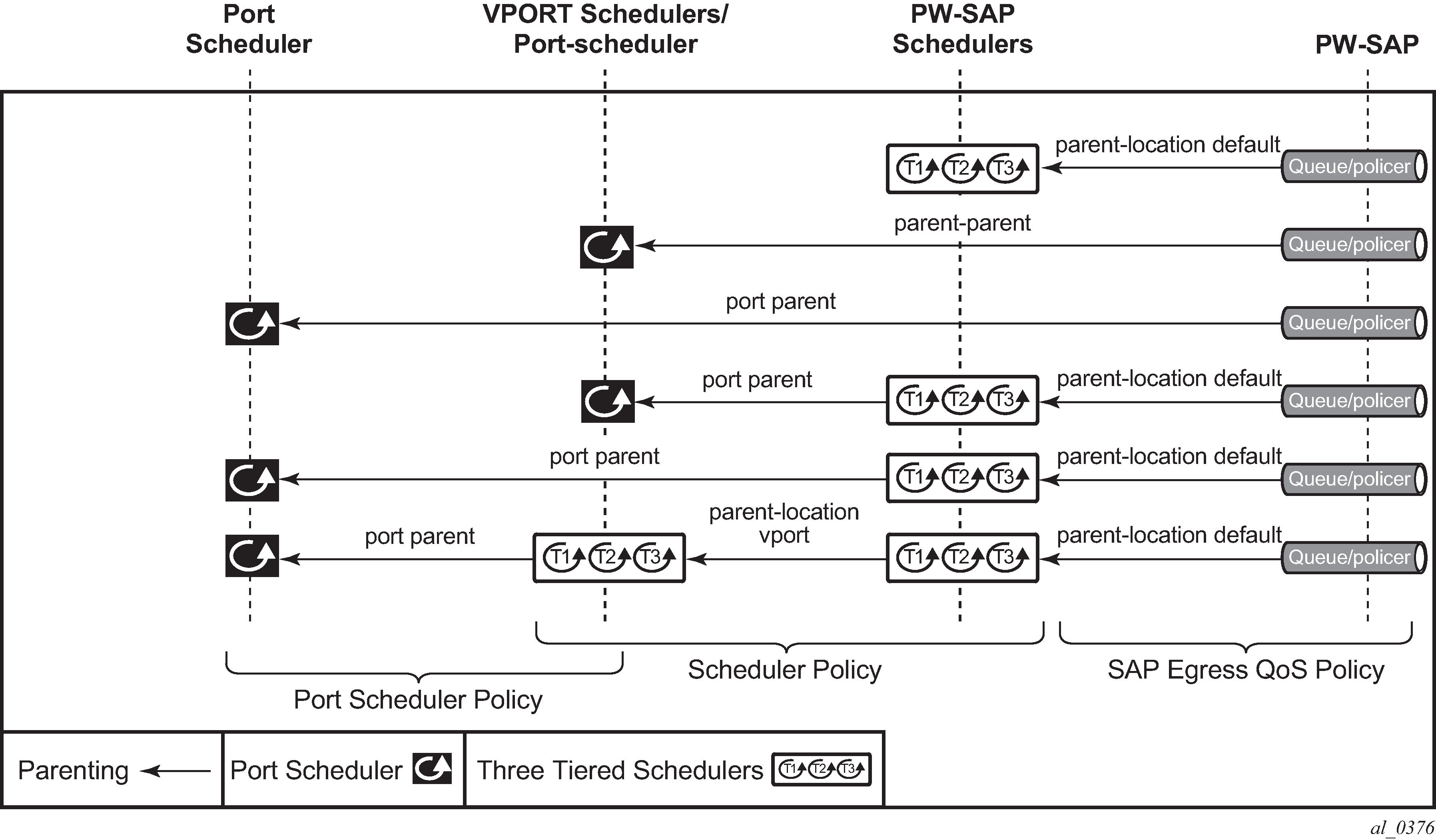
To make use of a scheduler under a Vport, PW SAP schedulers must be configured with a parent command and the parent-location vport under tier 1 of the scheduler policy. The egress hierarchical parenting relationship options are shown in PW SAP egress scheduling hierarchy options. See the 7450 ESS, 7750 SR, 7950 XRS, and VSR Quality of Service Guide Quality of Service guide for more information.
Lag considerations
PW ports may be bound to Vport schedulers bound to a LAG. However, if the LAG is configured in distributed mode, then bandwidth is shared according to the active LAG members across a single IOM. If the LAG spans multiple IOMs, then it effectively operates in link mode across the IOMs. That is, the full LAG bandwidth is allocated to the LAG members on each IOM. Therefore, the use of a Vport on a distributed mode LAG with a port scheduler on the port or Vport and PW SAPs is explicitly not supported and is not a recommended configuration. It is recommended that port-fair mode is used instead.
Last mile packet size adjustment
In the application where pseudowire SAPs are used to apply access QoS for services aggregated from an Ethernet access network, MPLS labels may not be present on the last-mile and link from an access node. In these cases, policers, queues, and H-QoS schedulers should account for packets without MPLS overhead, modeled as ‟encaps-offset”. Vport and port schedulers behave as per the table below. In the datapath, the actual pseudowire encap overhead (taking into account the MPLS labels) added to the packet is tracked, and may be applied to the scheduler calculations via the configured packet byte offset.
The rate limit configured for the pseudowire SAP accounts for subscriber or service frame wire rate: without MPLS overhead and including the last mile overhead (unless a packet byte offset is configured).
Packet sizes used for pseudowire SAPs summarizes the default packet sizes used at each of the schedulers on the IOM/Ethernet MDA, assuming a 1000 byte customer packet.
| Type | Size |
|---|---|
exp-secondary-shaper |
20B preamble + 26 MPLS + 1000B pkt |
port-scheduler rate |
20B preamble + 1000B pkt |
regular queue/policer rate |
1000B pkt |
vport agg-limit-rate |
20B preamble + 1000B pkt |
vport port-scheduler rate |
20B preamble + 1000B pkt |
vport scheduler rate |
1000B pkt |
vport scheduler to port-scheduler rates |
20B preamble + 1000B pkt |
Redundancy with pseudowire SAPs
This section describes a mechanism in which one end on a pseudowire (the "master") dictates the active PW selection, which is followed by the other end of the PW (the 'standby'). This mechanism and associated terminology is specified in RFC6870.
Within a chassis, IOM and port based redundancy is based on active/backup LAG. The topology for the base MPLS LSP used by the SDP could be constrained such that it could get re-routed in the aggregation network, but would always appear on the LAG ports on the Layer 3 PE. In the case that the tunnel is re-routed to a different port, the MPLS pseudowire SAPs would be brought down.
To provide Layer 3 PE redundancy, dual homing of the access PE into separate Layer 3 PEs using active/standby pseudowire status is supported. This is shown in Dual homing into multiple Layer 3 PEs.
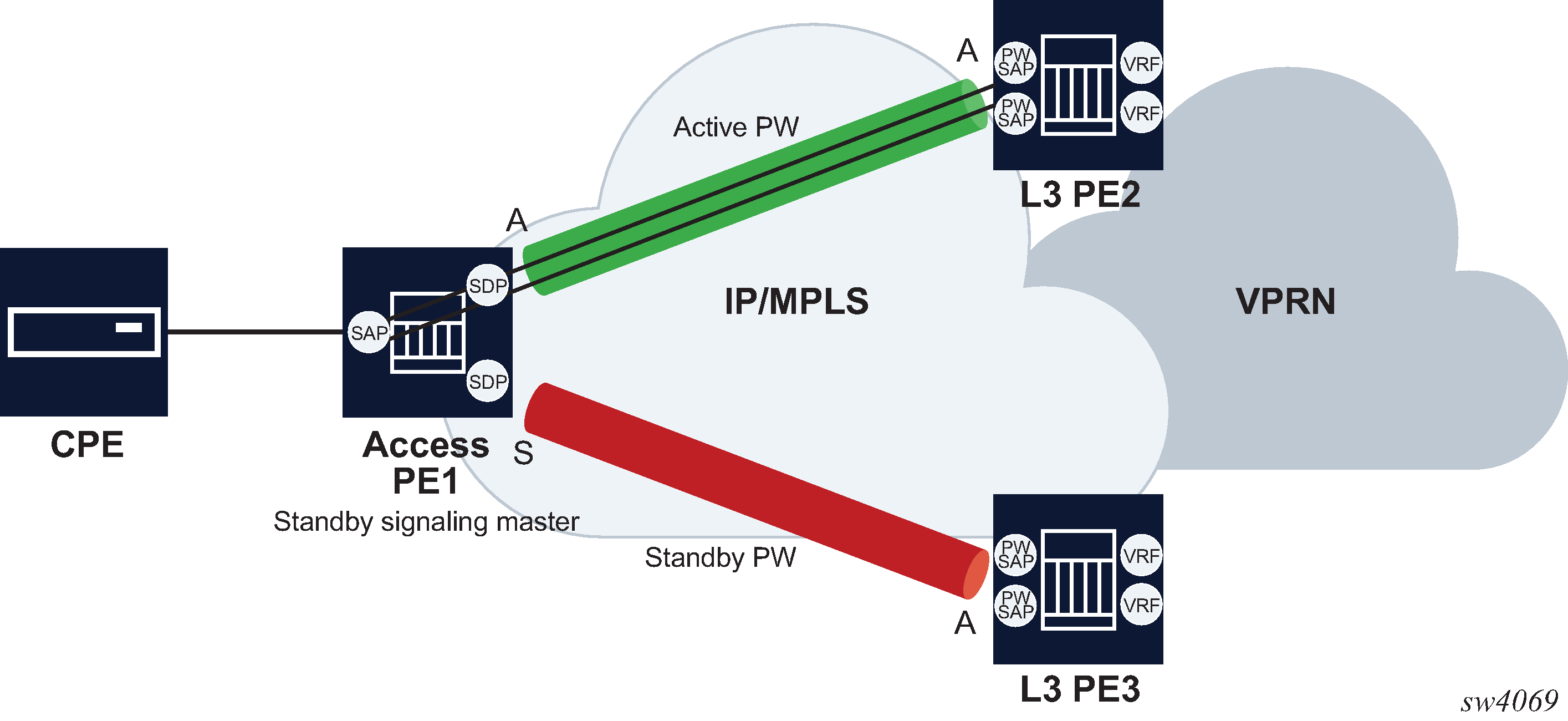
Dual homing operates in a similar manner to Spoke-SDP termination on IES/VPRN. Dual homing into multiple Layer 3 PEs displays the access PE is dual-homed to the Layer 3 PEs using two spoke-SDPs. Use the following commands to configure the endpoint in the access PE to be the master from a pseudowire redundancy perspective:
- MD-CLI
configure service ipipe endpoint standby-signaling master configure service epipe endpoint standby-signaling master - classic
CLI
configure service ipipe endpoint standby-signaling-master
configure service epipe endpoint standby-signaling-master
The access PE picks one of the spoke SDPs to make active, and one to make standby, based on the local configuration of primary or spoke SDP precedence.
The pseudowire port at the Layer 3 PE behaves as a standby from the perspective of pseudowire status signaling. That is, if its peer signals ‟PW FWD standby (0x20)” status bit for the specific Spoke-SDP and the local configuration does not allow this bit to be ignored, the PE takes the pseudowire port to a local operationally down state. This is consistent with the Spoke-SDP behavior for the case of Spoke-SDP termination on IES/VPRN.
As a consequence, all of the pseudowire SAPs bound to the pseudowire port are taken down, which causes the corresponding IES or VPRN interface to go to a local operationally down state and therefore stops forwarding packets toward this pseudowire port.
Conversely, the formerly standby pseudowire is made active and then the corresponding pseudowire port on the second Layer 3 PE is taken locally operationally up. Therefore, all of the pseudowire SAPs bound to the pseudowire port are brought up, which causes the corresponding IES or VPRN interface to go to a local operationally up state allowing forwarding of packets toward this pseudowire port.
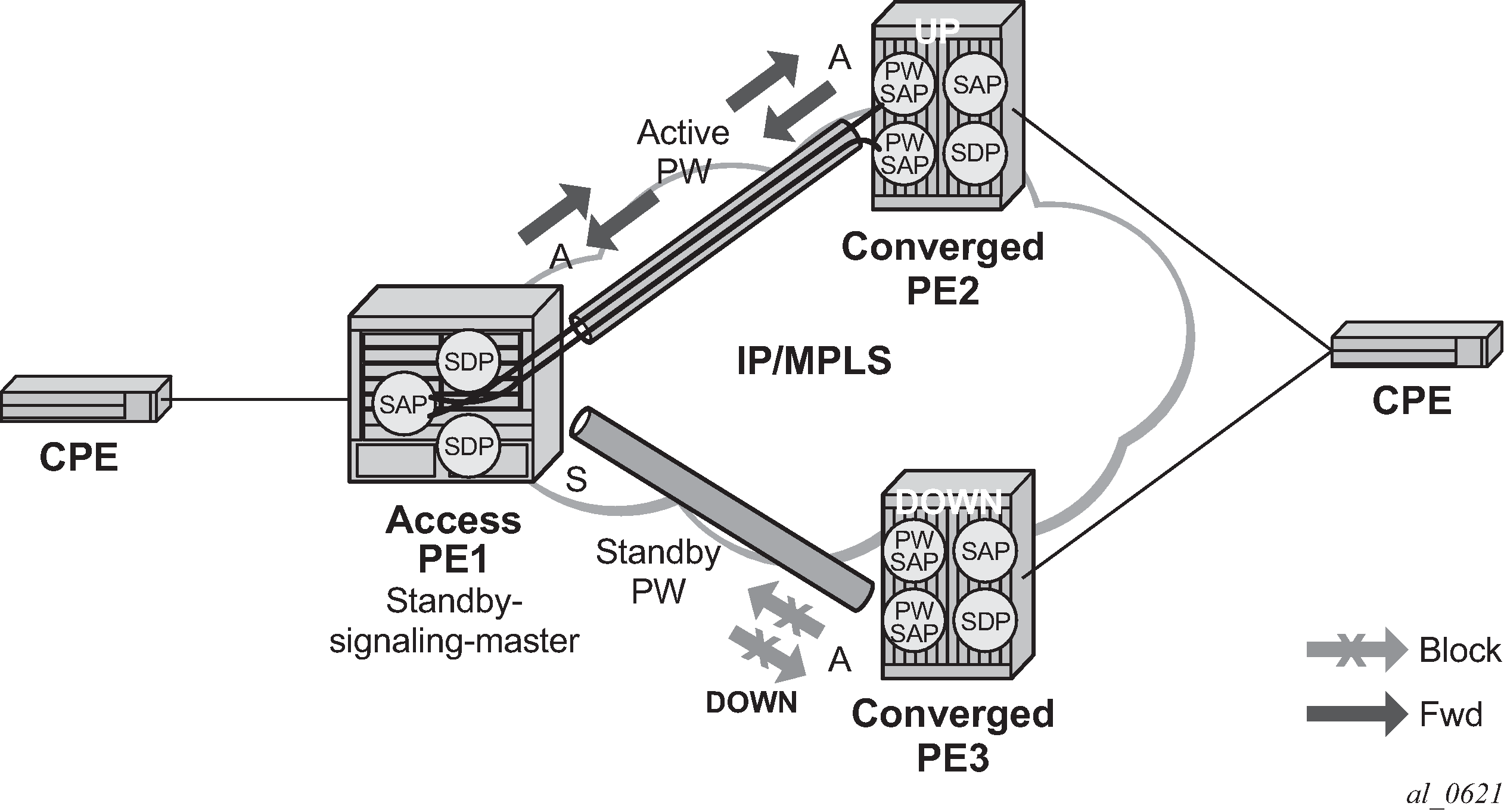
For VLLs, a PW port always behaves as a standby from the perspective of PW redundancy. This is because the PW port is taken locally operationally down if any non-zero PW status (including a PW Preferential Forwarding status of standby) is received. Master-standby PW redundancy mechanisms for dual homing of the access PE into separate converged PEs using active or standby PW status are supported as shown in Master-standby PW redundancy . However, this is only applicable to VLL services consisting of only SAPs, PW-SAPs, or spoke-SDPs. Dual-homing redundancy, taking into account the status of the PW SAP, is not supported where a PBB tunnel between the two converged PEs exists in the Epipe VLL service.
As in the existing implementation, standby signaling is configured to master on the spoke SDP at the access PE. However, explicit configuration of standby signaling to the standby on the PW port is not required, as this is the default behavior.
The forwarding behavior is the same as when standby-signaling is configured to standby for Epipe spoke SDPs. That is, when enabled, if a PW Forwarding Standby (0x20) LDP status message is received for the P11111111W, then the transmit direction is blocked for the PW port. All PW SAPs bound to the corresponding PW port are treated from a SAP OAM perspective in the same manner as a fault on the service, such as an SDP-binding down or remote SAP down.
PW redundancy with multiple active/standby PW ports or PW SAPs bound to the same Ethernet SAP in the converged PE is not supported. The independent mode of operation for PW redundancy is not also supported for a PW port.
Operational group support for PW ports
A PW port state may be linked to the state of an operational group, such that if the operational group goes down, the SDP binding for the PW port also goes operationally down, and therefore the corresponding PW status bit signaled (0x00000001 - Pseudowire Not Forwarding). If a status of 0x00000001 is signaled for a currently active PW, and active/standby dual homing is in use then the access PE fails over to the standby PW to the standby converged PE.
This is achieved by linking an SDP binding to an operational group for PW SAPs belonging to any supported service types (including those with group interfaces) bound to that PW port, such as IES, VPRN, or Epipe VLL.
Associate an operational group at the SDP binding level (MD-CLI)
[ex:/configure service]
A:admin@node-2# info
    sdp 1 {
        }
        pw-port {
            binding-port 1/1/1
        }
    }

[ex:/configure pw-port 1 sdp 1]
A:admin@node-2# info
    admin-state enable
    vc-id 11
    monitor-oper-group "test-oper-grp"
Associate an operational group at the SDP binding level (classic CLI)
A:node-2>config>service# info
----------------------------------------------
      sdp 1 create
            no shutdown
            binding
                port 1/1/1
                pw-port 1 vc-id 11 create
                    no shutdown
                    monitor-oper-group "test-oper-grp"
                exit
            exit
        exit
The monitor-oper-group command specifies the operational group to be monitored by the PW-Port under which it is configured. The operational group name must be already configured under the configure service context before its name is referenced in this command.
The following illustrates how a PW port can track the status of VPRN uplinks using monitor-oper-group.
Uplinks in a VPRN may be monitored using a BFD session on the network facing IP interfaces in a VPRN or on the network IP interfaces supporting the uplinks.
Configure an operational group to monitor the BFD session (MD-CLI)
[ex:/configure service]
A:admin@node-2# info
    oper-group "test-oper-grp" {
        bfd-liveness {
            router-instance "105"
            interface-name "vprn-if"
            dest-ip 10.0.0.20
        }
    }
Configure an operational group to monitor the BFD session (classic CLI)
A:node-2>config>service# info
----------------------------------------------
         oper-group "test-oper-grp" create
            bfd-enable interface "vprn-if" dest-ip 10.0.0.20 service 105
Alternatively, the state of network interfaces can be monitored as follows.
Configure the monitoring of network interfaces (MD-CLI)
[ex:/configure service]
A:admin@node-2# info
    oper-group "test-oper-grp" {
        bfd-liveness {
            interface-name "network-if"
            dest-ip 10.0.1.20
        }
    }
Configure the monitoring of network interfaces (classic CLI)
A:node-2>config>service# info
----------------------------------------------
         oper-group "test-oper-grp" create
            bfd-enable interface "network-if" dest-ip 10.0.1.20
The PW port is then configured with monitor-oper-group as follows.
Configure the PW port with the monitor-oper-group option (MD-CLI)
[ex:/configure service]
A:admin@node-2# info
    sdp 1 {
        }
        pw-port {
            binding-port 1/1/2
        }
    }

[ex:/configure pw-port 100 sdp 1]
A:admin@node-2# info
    vc-id 25
    monitor-oper-group "test-oper-grp"
Configure the PW port with the monitor-oper-group option (classic CLI)
A:node-2>config>service>sdp>binding# info
----------------------------------------------
            port 1/1/2
            pw-port 100 vc-id 25 create
                shutdown
                monitor-oper-group "test-oper-grp"
            exit
----------------------------------------------
Routing protocols
The IES IP interfaces are restricted as to the routing protocols that can be defined on the interface based on the fact that the customer has a different routing domain for this service. The IES IP interfaces support the following routing protocols:
RIP
OSPF
IS-IS
BGP
IGMP
PIM
CPE connectivity check
Static routes are used within many IES services. Unlike dynamic routing protocols, there is no way to change the state of routes based on availability information for the associated CPE. CPE connectivity check adds flexibility so that unavailable destinations are removed from the service provider’s routing tables dynamically and minimize wasted bandwidth.
The availability of the far-end static route is monitored through periodic polling. The polling period is configured. If the poll fails a specified number of sequential polls, the static route is marked as inactive.
An ICMP ping mechanism is used to test the connectivity.
If the connectivity check fails and the static route is deactivated, the router continues to send polls and reactivate any routes that are restored.
QoS policies
When applied to IES services, service ingress QoS policies only create the unicast queues defined in the policy. The multipoint queues are not created on the service. With IES services, service egress QoS policies function as with other services where the class-based queues are created as defined in the policy. Both Layer 2 or Layer 3 criteria can be used in the QoS policies for traffic classification in an IES.
Filter policies
Only IP filter policies can be applied to IES services.
MPLS entropy label and hash label
The router supports both the MPLS entropy label (RFC 6790) and the Flow Aware Transport label, known as the hash label (RFC 6391). LSR nodes in a network to load-balance labeled packets in a more granular way than by hashing on the standard label stack. See the 7450 ESS, 7750 SR, 7950 XRS, and VSR MPLS Guide for more information.
The entropy label is supported for Epipe and Ipipe spoke-SDP termination on IES interfaces. To configure insertion of the entropy label on a spoke SDP that terminates on the service, use the entropy-label command in the spoke-sdp context of a specific interface.
The hash label is also supported for Epipe and Ipipe spoke SDP termination on IES services. Configure it using the hash-label command in the spoke-sdp context for an IES interface context.
Either the hash label or the entropy label can be configured on one object, but not both.
Spoke SDPs
Distributed services use service distribution points (SDPs) to direct traffic to another router through service tunnels. SDPs are created on each participating router and then bound to a specific service. SDP can be created as either GRE or MPLS. See the 7450 ESS, 7750 SR, 7950 XRS, and VSR Services Overview Guide for information about configuring SDPs.
This feature provides the ability to cross-connect traffic entering on a spoke SDP, used for Layer 2 services (VLLs or VPLS), on to an IES or VPRN service. From a logical point of view, the spoke SDP entering on a network port is cross-connected to the Layer 3 service as if it entered by a service SAP. The main exception to this is traffic entering the Layer 3 service by a spoke SDP is handled with network QoS policies and not access QoS policies.
This feature applies to the 7450 ESS and 7750 SR only.
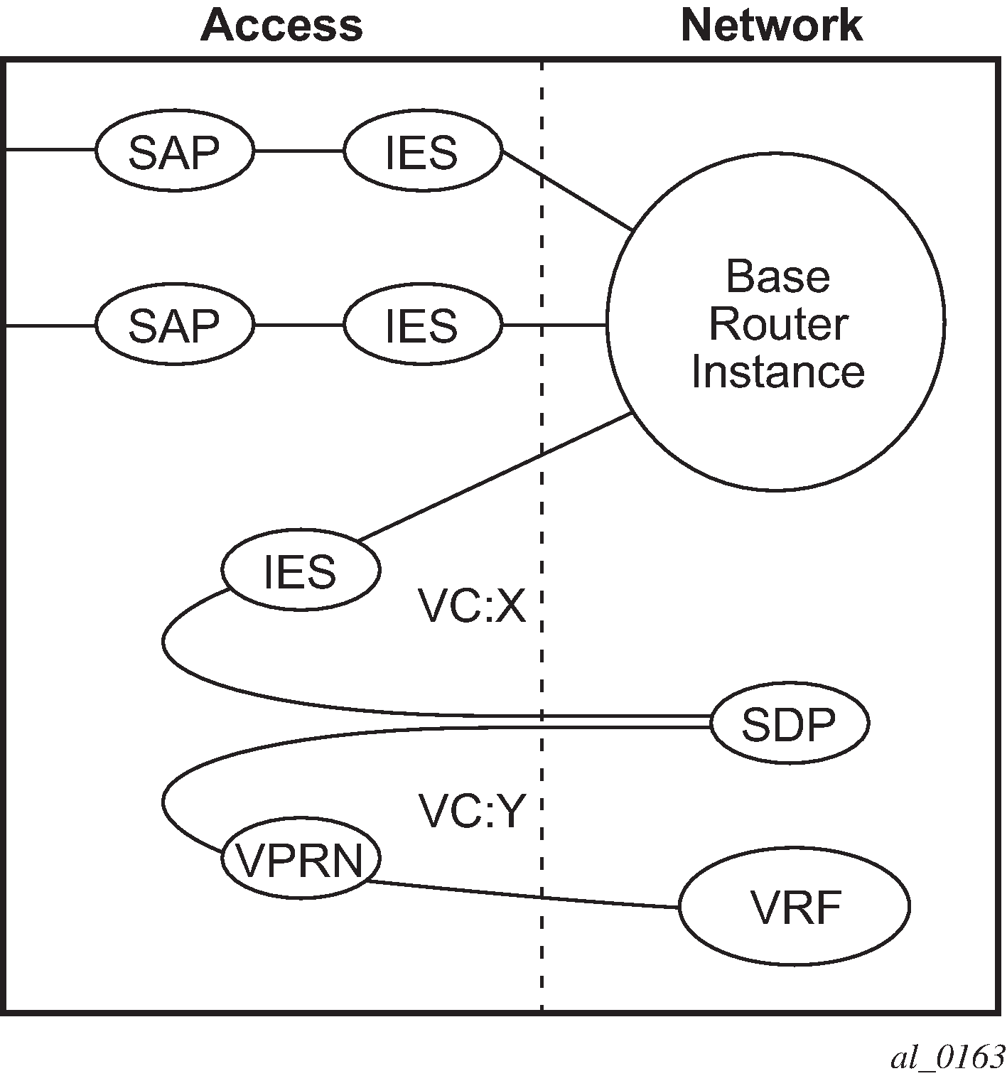
SDP-ID and VC label service identifiers depicts traffic terminating on a specific IES or VPRN service that is identified by the SDP-ID and VC label present in the service packet.
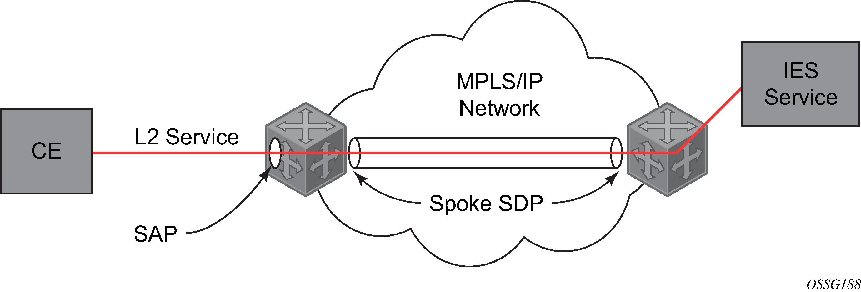
IES spoke-SDP termination depicts a spoke SDP terminating directly into a Layer 3 service interface (IES or VPRN) at one end, and a Layer 2 service (Epipe, Ipipe, or VPLS) at the other. There is no special configuration required on the Layer 2 service.
If the terminating Layer 2 service is an Ipipe, then on the IES/VPRN interface end, the spoke SDP must be created with the vc-type ipipe command option. Spoke SDPs created with vc-type ether (the default) are compatible with Epipe and VPLS services, as well as with other IES/VPRN interfaces.
If the MPLS network uses LDP signaling, then in order for a spoke SDP to function, the LDP binding MTUs at each end must match. For a Layer 2 service, the MTU of the local binding is 14 octets less than the configured service MTU (such as, binding MTU = service MTU - 14). For an IES or VPRN interface, the binding MTU is equal to either the configured ip-mtu of the interface, or the SDP’s path-mtu minus 14, whichever is lower. Use the following command to find the local and remote MTUs of all bindings.
show router ldp bindingsAll routing protocols that are supported by IES/VPRN are supported for spoke-SDP termination.
See "VCCV BFD support for VLL, spoke SDP termination on IES and VPRN, and VPLS services" in the 7450 ESS, 7750 SR, 7950 XRS, and VSR Layer 2 Services and EVPN Guide for information about using VCCV BFD in spoke-SDP termination.
show router ldp bindings servicesSRRP
Subscriber Router Redundancy Protocol (SRRP) is used on the 7750 SR and 7450 ESS and is closely tied to the multi-chassis synchronization (MCS) protocol used to synchronize information between redundant nodes. An MCS peer must be configured and operational when subscriber hosts have a redundant connection to two nodes. Subscriber hosts are identified by the ingress SAP, the host’s IP and MAC addresses. After a host is identified on one node, the MCS peering is used to inform the other node that the host exists and conveys the dynamic DHCP lease state information of the host. MCS creates a common association between the virtual ports (SAPs) shared by a subscriber. This association is configured at the MCS peering level by defining a tag for a port and range of SAPs. The same tag is defined on the other nodes peering context for another port (does not need to be the same port-ID) with the same SAP range. In this manner, a subscriber host and Dot1Q tag sent across the peering with the appropriate tag is mapped to the redundant SAP on the other node.
SRRP can only be configured on group interfaces. When SRRP is active on a group IP interface, the SRRP instance attempts to communicate through in-band (over the group IP interfaces SAPs) and out-of-band (over the group IP interfaces redundant IP interface) messages to a remote router. If the remote router is also running SRRP with the same SRRP instance ID, one router enters a master state while the other router enters a backup state. Because both routers are sharing a common SRRP gateway MAC address that is used for the SRRP gateway IP addresses and for proxy ARP functions, either node may act as the default gateway for the attached subscriber hosts.
For correct operation, each subscriber subnet associated with the SRRP instance must have a gateway address defined. The SRRP instance cannot be activated (no shutdown) unless each subscriber subnet associated with the group IP interface has an SRRP gateway IP address. After the SRRP instance is activated, new subscriber subnets cannot be added without a corresponding SRRP gateway IP address. SRRP state effect on subscriber hosts associated with group IP interface describes how the SRRP instance state is used to manage access to subscriber hosts associated with the group IP interface.
In the classic CLI, SRRP instances are created in the disabled state. You must administratively enable SRRP to activate SRRP in the SRRP context.
In the MD-CLI, SRRP instances are created in the enabled state.
Before activating an SRRP instance on a group IP interface, the following actions are required:
-
Add a SRRP gateway IP addresses to all subscriber subnets associated with the group IP interface, including subnets on subscriber IP interfaces associated as retail routing contexts (at least one subnet must be on the subscriber IP interface containing the group IP interface and its SRRP instance).
-
Create a redundant IP interface and associate it with the SRRP instances group IP interface for shunting traffic to the remote router when master.
-
Specify the group IP interface SAP used for SRRP advertisement and Information messaging.
Before activating an SRRP instance on a group IP interface, the following actions should be considered:
-
Associate the SRRP instance to a Multi-Chassis Synchronization (MCS) peering terminating on the neighboring router (the MCS peering should exist as the peering is required for redundant subscriber host management).
-
Define a description string for the SRRP instance.
-
Specify the SRRP gateway MAC address used by the SRRP instance (must be the same on both the local and remote SRRP instance participating in the same SRRP context).
-
Change the base priority for the SRRP instance.
-
Specify one or more VRRP policies to dynamically manage the SRRP instance base priority.
-
Specify a new keep alive interval for the SRRP instance.
SRRP state effect on subscriber hosts associated with group IP interface lists the SRRP’s state effect on subscriber hosts associated with group IP interfaces.
| SRRP state | ARP | Local proxy ARP enabled | Remote proxy ARP enabled | Subscriber host routing |
|---|---|---|---|---|
Disabled |
- Responds to ARP for all owned subscriber subnet IP addresses. - Will not respond to ARP for subscriber subnet SRRP gateway IP addresses. - All ARP responses contain the native MAC of the group IP interface (not the SRRP gateway MAC). |
- Responds to ARP for all subscriber hosts on the subscriber subnet. |
- Responds to ARP for all reachable remote IP hosts. |
- All routing out the group IP interface uses the native group IP interface MAC address. - The group IP interface redundant IP interface is not used. - Does not accept packets destined for the SRRP gateway MAC received on the group IP interface. |
Becoming Master (To enter becoming master state, a master must currently exist) |
- Responds to ARP for all owned subscriber subnet IP addresses (hardware address and source MAC = group IP interface native MAC). - Responds to ARP for subscriber subnet SRRP gateway IP addresses. (hardware address = SRRP gateway IP address, source MAC = group IP interface native MAC). |
- Responds to ARP for all subscriber hosts on the subscriber subnet (hardware address = SRRP gateway MAC address, source MAC = group IP interface native MAC). |
- Responds to ARP for all reachable remote IP hosts (hardware address = SRRP gateway MAC address, source MAC = group IP interface native MAC). |
- All routing out the group IP interface uses the native group IP interface MAC address. - Subscriber hosts mapped to the redundant IP interface are remapped to the group IP interface. - Does not accept packets destined for the SRRP gateway MAC received on the group IP interface. |
Master |
- Responds to ARP for all owned subscriber subnet IP addresses (hardware address and source MAC = group IP interface native MAC). - Responds to ARP for subscriber subnet SRRP gateway IP addresses (hardware address = SRRP gateway IP address, source MAC = group IP interface native MAC). |
- Responds to ARP for all subscriber hosts on the subscriber subnet (hardware address = SRRP gateway MAC address, source MAC = group IP interface native MAC). |
- Responds to ARP for all reachable remote IP hosts (hardware address = SRRP gateway MAC address, source MAC = group IP interface native MAC). |
- All routing out the group IP interface uses the SRRP gateway MAC address. - Subscriber hosts mapped to the redundant IP interface are remapped to the group IP interface. - Accepts packets destined for the SRRP gateway MAC received on the group IP interface. |
Becoming Backup (redundant IP interface operational) |
- Responds to ARP for all owned subscriber subnet IP addresses (hardware address and source MAC = group IP interface native MAC). - Does not respond to ARP for subscriber subnet SRRP gateway IP addresses. |
- Does not respond to ARP for any subscriber hosts on the subscriber subnet. |
- Does not respond to ARP for any remote IP hosts. |
- Does not route out the group IP interface for subscriber hosts associated with the subscriber subnet. - Accepts packets destined for the SRRP gateway MAC received on the group IP interface. - Subscriber hosts mapped to the group IP interface are remapped to the redundant IP interface. |
Becoming Backup (redundant IP interface not available) |
- Responds to ARP for all owned subscriber subnet IP addresses (hardware address and source MAC = group IP interface native MAC). - Does not respond to ARP for subscriber subnet SRRP gateway IP addresses. |
- Does not respond to ARP for any subscriber hosts on the subscriber subnet. |
- Does not respond to ARP for any remote IP hosts. |
- Will route out the group IP interface for subscriber hosts associated with the subscriber subnet using the group IP interface native MAC address. - Subscriber hosts mapped to the redundant IP interface are remapped to the group IP interface. - Accepts packets destined for the SRRP gateway MAC received on the group IP interface. |
Backup (redundant IP interface operational) |
- Responds to ARP for all owned subscriber subnet IP addresses (hardware address and source MAC = group IP interface native MAC). - Will not respond to ARP for subscriber subnet SRRP gateway IP addresses. |
- Does not respond to ARP for any subscriber hosts on the subscriber subnet. |
- Does not respond to ARP for any remote IP hosts. |
- Does not route out the group IP interface for subscriber hosts associated with the subscriber subnet. - Subscriber hosts mapped to the group IP interface are remapped to the redundant IP interface. - Does not accept packets destined for the SRRP gateway MAC received on the group IP interface. |
Backup (redundant IP interface not available) |
- Responds to ARP for all owned subscriber subnet IP addresses (hardware address and source MAC = group IP interface native MAC). - Does not respond to ARP for subscriber subnet SRRP gateway IP addresses. |
- Does not respond to ARP for any subscriber hosts on the subscriber subnet. |
- Does not respond to ARP for any remote IP hosts. |
- Routes out the group IP interface for subscriber hosts associated with the subscriber subnet using the group IP interface native MAC address. - Subscriber hosts mapped to the redundant IP interface are remapped to the group IP interface. - Does not accept packets destined for the SRRP gateway MAC received on the group IP interface. |
SRRP messaging
SRRP uses the same messaging format as VRRP with slight modifications. The source IP address is derived from the system IP address assigned to the local router. The destination IP address and IP protocol are the same as VRRP (224.0.0.18 and 112, respectively).
The message type field is set to 1 (advertisement) and the protocol version is set to 8 to differentiate SRRP message processing from VRRP message processing.
The vr-id field supports an SRRP instance ID of 32 bits.
Because of the large number of subnets backed up by SRRP, only one message every minute carries the gateway IP addresses associated with the SRRP instance. These gateway addresses are stored by the local SRRP instance and are compared with the gateway addresses associated with the local subscriber IP interface.
Unlike VRRP, only two nodes may participate in an SRRP instance due the explicit association between the SRRP instance group IP interface, the associated redundant IP interface and the multi-chassis synchronization (MCS) peering. Because only two nodes are participating, the VRRP skew timer is not used when waiting to enter the master state. Also, SRRP always preempts when the local priority is better than the current master and the backup SRRP instance always inherits the master’s advertisement interval from the SRRP advertisement messaging.
SRRP advertisement messages carry a becoming-master indicator flag. The becoming-master flag is set by a node that is attempting to usurp the master state from an existing SRRP master router. When receiving an SRRP advertisement message with a better priority and with the becoming-master flag set, the local master initiates its becoming-backup state, stops routing with the SRRP gateway MAC and sends an SRRP advertisement message with a priority set to zero. The new master continues to send SRRP advertisement messages with the becoming-master flag set until it either receives a return priority zero SRRP advertisement message from the previous master or its becoming-master state timer expires. The new backup node continues to send zero priority SRRP advertisement messages every time it receives an SRRP advertisement message with the becoming-master flag set. After the new master either receives the old masters priority zero SRRP advertisement message or the become-master state timer expires, it enters the master state. The become-master state timer is set to 10 seconds upon entering the become-master state.
The SRRP advertisement message is always evaluated to see if it has a higher priority than the SRRP advertisement that would be sent by the local node. If the advertised priority is equal to the current local priority, the source IP address of the received SRRP advertisement is used as a tie breaker. The node with the lowest IP address is considered to have the highest priority. SRRP does not preempt when priorities are equal. Preemption occurs only when priorities are specified. The lower IP address is only used as a tie-breaker when there is no master in the network. In other words, when both routers are changing from the ‟init” state, the lower IP is used to choose the master. If a master already exists, despite having the lower IP address, the system does not preempt the current master.
The SRRP instance maintains the source IP address of the current master. If an advertisement is received with the current masters source IP address and the local priority is higher priority than the masters advertised priority, the local node immediately enters the becoming-master state unless the advertised priority is zero. If the advertised priority is zero, the local node bypasses the becoming-master state and immediately enters the master state. Priority zero is a special case and is sent when an SRRP instance is relinquishing the master state.
SRRP and multi-chassis synchronization
To take full advantage of SRRP resiliency and diagnostic capabilities, the SRRP instance should be tied to a MCS peering that terminates on the redundant node. The SRRP instance is tied to the peering using the srrp-instance srrp-id command within the appropriate MCS peering configuration. After the peering is associated with the SRRP instance, MCS synchronizes the local information about the SRRP instance with the neighbor router. MCS automatically derives the MCS key for the SRRP instance based on the SRRP instance ID. For example, an SRRP instance ID of 1 would appear in the MCS peering database with a MCS-key srrp-0000000001.
The SRRP instance information stored and sent to the neighbor router consists of the following:
-
SRRP instance MCS key
-
containing service type and ID
-
containing subscriber IP interface name
-
subscriber subnet information
-
containing group IP interface information
-
SRRP group IP interface redundant IP interface name, IP address and mask
-
SRRP advertisement message SAP
-
local system IP address (SRRP advertisement message source IP address)
-
group IP interface MAC address
-
SRRP gateway MAC address
-
SRRP instance administration state (up / down)
-
SRRP instance operational state (disabled / becoming-backup / backup / becoming-master / master)
-
current SRRP priority
-
remote redundant IP interface availability (available / unavailable)
-
local receive SRRP advertisement SAP availability (available / unavailable)
SRRP instance
The SRRP instance uses the received information to verify provisioning and obtain operational status of the SRRP instance on the neighboring router.
SRRP instance MCS key
The SRRP instance MCS key ties the received MCS information to the local SRRP instance with the same MCS key. If the received key does not match an existing SRRP instance, the MCS information associated with the key is ignored. After an SRRP instance is created and mapped to an MCS peering, the SRRP instance evaluates received information with the same MCS key to verify it corresponds to the same peering. If the received MCS key is on a different peering than the local MCS key an SRRP peering mismatch event is generated detailing the SRRP instance ID, the IP address of the peering the MCS key is received on and the IP address to which the local MCS key is mapped. If the peering association mismatch is corrected, an SRRP peering mismatch clear event is generated.
Containing service type and ID
The Containing Service Type is the service type (IES or VPRN) that contains the local SRRP instance. The Containing Service ID is the service ID of that service. This information is supplied for troubleshooting purposes only and is not required to be the same on both nodes.
Containing subscriber IP interface name
The containing subscriber IP interface name is the subscriber IP interface name that contains the SRRP instance and its group IP interface. This information is supplied for troubleshooting purposes only and is not required to be the same on both nodes.
Subscriber subnet information
The subscriber subnet information includes all subscriber subnets backed up by the SRRP instance. The information for each subnet includes the Owned IP address, the mask and the gateway IP address. If the received subscriber subnet information does not match the local subscriber subnet information, an SRRP Subscriber Subnet Mismatch event is generated describing the SRRP instance ID and the local and remote node IP addresses. When the subscriber subnet information matches, an SRRP Subscriber Subnet Mismatch Clear event is generated.
Containing group IP interface information
The containing group IP interface information is the information about the group IP interface that contains the SRRP instance. The information includes the name of the group IP interface, the list of all SAPs created on the group IP interface, the administrative and operational state of each SAP and the MCS key and the peering destination IP address associated with each SAP. To obtain the MCS information, the SRRP instance queries MCS to determine the peering association of the SRRP instance and then queries MCS for each SAP on the group IP interface. If the local SRRP instance is associated with a different MCS peering than any of the SAPs or if one or more SAPs are not tied to an MCS peering, an SRRP group interface SAP peering mismatch event is generated detailing the SRRP instance ID, and the group IP interface name.
When receiving the remote containing group IP interface information, the local node compares the received SAP information with the local group IP interface SAP information. If a local SAP is not included in the SAP information or a remote SAP is not included in the local group IP interface, an SRRP Remote SAP mismatch event is generated detailing the SRRP instance ID and the local and remote group IP interface names. If a received SAP’s MCS key does not match a local SAP’s MCS Key, an SRRP SAP MCS key mismatch event is generated detailing the SRRP instance ID, the local and remote group IP interface names, the SAP-ID and the local and remote MCS keys.
Remote redundant IP interface mismatch
If the group IP remote redundant IP interface address space does not exist, is not within the local routing context for the SRRP instances group IP interface or is not on a redundant IP interface, the local node sends redundant IP interface unavailable to prevent the remote neighbor from using its redundant IP interface. An SRRP redundant IP interface mismatch event is generated for the SRRP instance detailing the SRRP instance, the local and remote system IP addresses, the local and remote group IP interface names and the local and remote redundant IP interface names and IP addresses and masks. The local redundant IP interface may still be used if the remote node is not sending redundant IP interface unavailable.
Remote sending redundant IP interface unavailable
If the remote node is sending redundant IP interface unavailable, the local node treats the local redundant IP interface associated with the SRRP instances group IP interface as down. A Local Redundant IP Interface Unavailable event is generated detailing the SRRP instance ID, the local and remote system IP addresses, the local group IP interface name, the local redundant IP interface name and the redundant IP interface IP address and mask.
Remote SRRP advertisement SAP non-existent
If the remote node’s SRRP advertisement SAP does not exist on the local SRRP instances group IP interface, the local node sends local receive SRRP advertisement SAP unavailable to the remote node. An SRRP receive advertisement SAP non-existent event is generated detailing the SRRP instance ID, the local and remote system IP addresses, the local group IP interface name and the received remote SRRP advertisement SAP. Because SRRP advertisement messages cannot be received, the local node immediately becomes master if it has the lower system IP address.
Remote sending local receive SRRP advertisement SAP unavailable
If the local node is receiving local receive SRRP advertisement SAP unavailable from the remote node, an SRRP Remote Receive advertisement SAP Unavailable event is generated detailing the SRRP instance ID, the local and remote system IP addresses, the remote group IP interface name and the local SRRP advertisement SAP. Because the remote node cannot receive SRRP advertisement messages, the local node immediately becomes master if it has the lower system IP address.
Local and remote dual master detected
If the local SRRP state is master and the remote SRRP state is master, an SRRP dual master event is generated detailing the SRRP instance ID and the local, remote system IP addresses and the local and remote group IP interface names and port numbers.
Subscriber subnet owned IP address connectivity
In order for the network to reliably reach the owned IP addresses on a subscriber subnet, it is not necessary for the owning node to advertise the IP addresses as /32 host routes into the core. Network reachability to the subscriber subnet is advertised into the IGP core by both of the dual homing nodes. The shortest path to the subscriber may not always traverse the active path for a subscriber. In this case, the path traverses the non-active/primary node for the subscriber and the traffic is redirected through the redundant interface to the other node through the redundant interface to the active path. This ensures that all downstream traffic to a subscriber always flows through one node.
Subscriber subnet SRRP gateway IP address connectivity
The SRRP gateway IP addresses on the subscriber subnets cannot be advertised as /32 host routes because they may be active (master) on multiple group IP interfaces on multiple SRRP routers. Without a /32 host route path, the network forwards any packet destined for an SRRP gateway IP address to the closest router advertising the subscriber subnet. While a case may be made that only a node that is currently forwarding for the gateway IP address in a master state should respond to ping or other diagnostic messages, the distribution of the subnet and the case of multiple masters make any resulting response or non-response inconclusive at best. To provide some ability to ping the SRRP gateway address from the network side reliably, any node receiving the ICMP ping request responds if the gateway IP address is defined on its subscriber subnet.
Receive SRRP advertisement SAP and anti-spoof
The group IP interface SAPs are designed to support subscriber hosts and perform an ingress anti-spoof function that ensures that any IP packet received on the group IP interface is coming in the correct SAP with the correct MAC address. If the IP and MAC are not registered as valid subscriber hosts on the SAP, the packet is silently discarded. Because the SRRP advertisement source IP addresses are not subscriber hosts, an anti-spoof entry does not exist and SRRP advertisement messages would normally be silently discarded. To avoid this issue, when a group IP interface SAP is configured to send and receive SRRP advertisement messages, anti-spoof processing on the SAP is disabled. This precludes subscriber host management on the SRRP messaging SAP.
BFD with SRRP/VRRP
BFD with SRRP is supported. This allows the use of longer timers inside SRRP resulting in more SRRP instances while still retaining fast failure detection with BFD.
Configuring an IES service with CLI
This section provides information to configure IES services using the command line interface.
Basic configuration
The most basic IES service configuration has the following entities:
customer ID (see the 7450 ESS, 7750 SR, 7950 XRS, and VSR Services Overview Guide for more information)
an interface to create and maintain IP routing interfaces within IES service ID
a SAP on the interface specifying the access port and encapsulation values
The following example shows the configuration of an IES service.
MD-CLI
[ex:/configure service]
A:admin@node-2# info
    ies "1000" {
        admin-state enable
        description "to internet"
        customer "1"
        vpn-id 1000
        interface "to-web" {
            sap 1/1/5:0.* {
            }
            ipv4 {
                primary {
                    address 10.1.1.1
                    prefix-length 24
                }
            }
        }
    }
classic CLI
A:node-2>config>service# info
----------------------------------------------
        ies 1000 name "1000" customer 1 vpn 1000 create
            description "to internet"
            interface "to-web" create
                address 10.1.1.1/24
                sap 1/1/5:0.* create
                exit
            exit
            no shutdown
        exit
----------------------------------------------
Common configuration tasks
This section provides a brief overview of the tasks that must be performed to configure IES services and provides the CLI commands.
- Associate an IES service with a customer ID.
- Associate customer ID with the service.
- Assign an IP address.
- Create a subscriber interface (for 7450 ESS and 7750 SR only and optional).
- Create an interface.
-
Define SAP command options on the interface:
-
Select nodes and ports.
-
Optionally, select the following policies:
-
QoS policies other than the default (configured in the configure qos context); for 7450 ESS and 7750 SR only
-
filter policies (configured in the configure filter context)
-
accounting policy (configured in the configure log context); for 7450 ESS and 7750 SR only
-
-
- Enable service.
Configuring IES components
Use the configuration information that follows to configure IES components.
Configuring an IES service
The following example displays a basic IES service configuration.
IES service configuration for the 7450 ESS, 7450 ESS, and 7750 SR (MD-CLI)
[ex:/configure service]
A:admin@node-2# info
    ies "1001" {
        admin-state enable
        description "to-internet"
        customer "1"
        vpn-id 1001
    }
IES service configuration for the 7450 ESS and 7750 SR (classic CLI)
A:node-2>config>service# info
----------------------------------------------
        ies 1001 name "1001" customer 1 vpn 1001 create
            description "to-internet"
            no shutdown
        exit
----------------------------------------------
Basic IES service configuration for the 7950 XRS (MD-CLI)
[ex:/configure service]
A:admin@node-2# info
    ies "1001" {
        admin-state enable
        description "to-internet"
        customer "1"
    }
Basic IES service configuration for the 7950 XRS (classic CLI)
A:node-2>config>service# info
----------------------------------------------
        ies 1001 name "1001" customer 1 create
            description "to-internet"
            no shutdown
        exit
----------------------------------------------
Configuring IES subscriber interfaces
Subscriber interfaces operate only with basic (or enhanced) subscriber management. At the very least, a host, either statically configured or dynamically learned by DHCP must be present in order for the interface to be useful.
The following example displays a subscriber interface configuration for the 7750 SR.
MD-CLI
[ex:/configure service ies "11" subscriber-interface "test1"]
A:admin@node-2# info
    ipv4 {
        address 192.168.140.1 {
            prefix-length 24
        }
    }
    group-interface "abc-if" {
        sap 1/1/19:0 {
            ingress {
                qos {
                    sap-ingress {
                        policy-name "2"
                    }
                }
                filter {
                    ip "10"
                }
            }
            static-host {
                ipv4 192.168.145.100 mac 00:01:00:00:00:01 {
                }
            }
        }
classic CLI
A:node-2>config>service>ies>sub-if# info
----------------------------------------------
                address 192.168.140.1/24
                group-interface "abc-if" create
                    sap 1/1/19:0 create
                        ingress
                            qos 2
                            filter ip 10
                        exit
                        static-host ip 192.168.145.100 mac 00:01:00:00:00:01 create
                        exit
                    exit
                exit
----------------------------------------------
Configuring IES interfaces
The following examples show the configuration of IES interfaces.
IES configuration for the 7450 ESS and 7750 SR (MD-CLI)
[ex:/configure service ies "2" interface "test2"]
A:admin@node-2# info
    sap 1/1/10:0.* {
        ingress {
            qos {
                sap-ingress {
                    policy-name "100"
                }
            }
        }
        egress {
            qos {
                scheduler-policy {
                    policy-name "SLA1"
                }
            }
        }
    }
    ipv4 {
        primary {
            address 10.1.1.1
            prefix-length 24
        }
        vrrp 1 {
            authentication-key "McTNkSePNJMVFysxyZa4y4D+iaD7lJ4= hash2"
        }
    }
IES configuration for the 7450 ESS and 7750 SR (classic CLI)
A:node-2>config>service>ies>if$ info
----------------------------------------------
                address 10.1.1.1/24
                vrrp 1 owner
                    authentication-key "McTNkSePNJMVFysxyZa4y4D+iaD7lJ4=" hash2
                exit
                sap 1/1/10:0.* create
                    ingress
                        qos 100
                    exit
                    egress
                        scheduler-policy "SLA1"
                    exit
                exit
----------------------------------------------
IES configuration for the 7950 XRS (MD-CLI)
[ex:/configure service ies "13" interface "test3"]
A:admin@node-2# info
    sap 1/1/10:0.* {
    }
    ipv4 {
        primary {
            address 10.1.1.1
            prefix-length 24
        }
    }
IES configuration for the 7950 XRS (classic CLI)
A:node-2>config>service>ies>if# info
----------------------------------------------
                address 10.1.1.1/24
                sap 1/1/10:0.* create
                exit
----------------------------------------------
Configuring a spoke SDP
The following example shows a spoke-SDP configuration for the 7450 ESS and 7750 SR.
MD-CLI
[ex:/configure service ies "4"]
A:admin@node-2# info
    admin-state enable
    description "to internet"
    customer "1"
    interface "spokeSDP-test" {
        spoke-sdp 2:100 {
            egress {
                filter {
                    ip "10"
                }
            }
        }
    }
classic CLI
A:node-2>config>service>ies# info
----------------------------------------------
            description "to internet"
            interface "spokeSDP-test" create
                spoke-sdp 2:100 create
                    egress
                        filter ip 10
                    exit
                exit
            exit
            no shutdown
----------------------------------------------
Configuring a SAP
A service access point (SAP) is a combination of a port and encapsulation command options that identifies the SAP on the interface and within the router. Each SAP must be unique within a router.
When configuring IES SAP command options on a 7450 ESS or 7750 SR, a default QoS policy is applied to each ingress and egress SAP. Additional QoS policies and scheduler policies must be configured in the configure qos context. Filter policies are configured in the configure filter context and must be explicitly applied to a SAP. There are no default filter policies.
IES SAP configuration for the 7450 ESS and 7750 SR (MD-CLI)
[ex:/configure service ies "2"]
A:admin@node-2# info
    customer "1"
    interface "test2" {
        sap 5/1/3.1:0 {
            ingress {
                qos {
                    sap-ingress {
                        policy-name "101"
                    }
                }
            }
            egress {
                qos {
                    sap-egress {
                        policy-name "1010"
                    }
                    scheduler-policy {
                        policy-name "alpha"
                    }
                }
            }
        }
        ipv4 {
            primary {
                address 10.10.36.2
                prefix-length 24
            }
        }
    }
IES SAP configuration for the 7450 ESS and 7750 SR (classic CLI)
A:node-2>config>service>ies>if# info
----------------------------------------------
                address 10.10.36.2/24
                sap 5/1/3.1:0 create
                    ingress
                        qos 101
                    exit
                    egress
                        scheduler-policy "alpha"
                        qos 1010
                    exit
                exit
----------------------------------------------
IES SAP configuration for the 7950 XRS (MD-CLI)
[ex:/configure service ies "3"]
A:admin@node-2# info
        ipv4 {
            primary {
                address 10.10.36.2
                prefix-length 24
            }
        }
    }
IES SAP configuration for the 7950 XRS (classic CLI)
A:node-2>config>service>ies>if# info
----------------------------------------------
                address 10.10.36.2/24
                exit
----------------------------------------------
Configuring VRRP
Configuring VRRP on an IES interface is optional and applies only to the 7450 ESS and 7750 SR. VRRP can be configured in either an owner or non-owner mode. The owner is the VRRP router whose virtual router IP address is the same as the real interface IP address. This is the router that responds to packets addressed to one of the IP addresses for ICMP pings, TCP connections, and so on. All other virtual router instances participating in this message domain must have the same VRID configured and cannot be configured as owner.
See the 7450 ESS, 7750 SR, 7950 XRS, and VSR Router Configuration Guide for more information about VRRP.
The following example shows the VRRP on an IES interface configuration.
MD-CLI
[ex:/configure service ies "16"]
A:admin@node-2# info
    customer "1"
    interface "test16" {
        ipv4 {
            primary {
                address 10.10.36.2
                prefix-length 24
            }
            vrrp 2 {
                authentication-key "McTNkSePNJMVFysxyZa4y1fsBIiad0g= hash2"
                backup [10.10.36.2]
                owner true
            }
        }
    }
classic CLI
A:node-2>config>service>ies>if$ info
----------------------------------------------
                address 10.10.36.2/24
                vrrp 2 owner
                    backup 10.10.36.2
                    authentication-key "McTNkSePNJMVFysxyZa4y1fsBIiad0g=" hash2
                exit
----------------------------------------------
Configuring IPsec
The following example shows an IES service with IPsec configured for the 7750 SR.
MD-CLI
[ex:/configure service]
A:admin@node-2# info
    ies "100" {
        admin-state enable
        customer "1"
        interface "ipsec-public" {
            admin-state enable
            sap ipsec-1.public:1 {
            }
            ipv4 {
                primary {
                    address 10.10.10.1
                    prefix-length 24
                }
            }
        }
    }
classic CLI
A:node-2>config# info
----------------------------------------------
...
    service
        ies 100 customer 1 create
            interface "ipsec-public" create
                address 10.10.10.1/24
                sap ipsec-1.public:1 create
                exit
            exit
            no shutdown
        exit
    exit
...
----------------------------------------------
IGMP host tracking
The following example shows an IES service with IGMP host tracking configured.
MD-CLI
[ex:/configure service]
A:admin@node-2# info
...
    ies "25" {
        admin-state enable
        customer "1"
        interface "ip_if_4" {
            ip-mtu 9000
            tos-marking-state untrusted
            sap lag-64:64 {
            }
            hold-time {
                ipv4 {
                    down {
                        seconds 1200
                    }
                }
            }
            ipv4 {
                allow-directed-broadcasts true
                local-dhcp-server "server 1"
                urpf-check {
                }
                primary {
                    address 10.64.64.64
                    prefix-length 24
                }
                secondary 10.3.4.5 {
                    prefix-length 24
                }
                neighbor-discovery {
                    local-proxy-arp true
                    remote-proxy-arp true
                    proxy-arp-policy ["treetrace-1"]
                }
                dhcp {
                    admin-state enable
                    description "server 1"
                    server [192.168.17.1]
                }
            }
        }
        igmp-host-tracking {
            expiry-time 65535
        }
classic CLI
A:node-2>config>service# info
----------------------------------------------
...
        ies 25 name "25" customer 1 create
            shutdown
            igmp-host-tracking
                expiry-time 65535
                no shutdown
            exit
            interface "ip_if_4" create
                hold-time
                    down ip 1200
                exit
                address 10.64.64.64/24
                secondary 10.3.4.5/24
                allow-directed-broadcasts
                tos-marking-state trusted
                dhcp
                    shutdown
                    description "server 1"
                    server 192.168.17.1
                exit
                ip-mtu 9000
                local-dhcp-server "server 1"
                local-proxy-arp
                proxy-arp-policy treetrace-1
                remote-proxy-arp
                sap lag-64:64 create
                exit
                urpf-check
                exit
            exit
        exit
Service management tasks
This section describes the IES service management tasks.
Modifying IES service command options
Existing IES service command options in the CLI or NMS can be modified, added, removed, enabled or disabled. Changes you make are applied immediately to all services.
To display a list of customer IDs, use the show service customer command. Enter the command options (such as description, SAP information and SDP information), and then enter the new information.
Modified service configuration for 7450 ESS and 7750 SR (MD-CLI)
[ex:/configure service]
A:admin@node-2# info
    ies "1000" {
        admin-state enable
        description "This is a new description"
        customer "1"
        vpn-id 1000
        interface "to-web" {
            mac 00:dc:98:1d:00:00
            sap 22/1/50:0 {
            }
            ipv4 {
                allow-directed-broadcasts true
                primary {
                    address 10.1.1.1
                    prefix-length 24
                }
            }
        }
    }
Modified service configuration for 7450 ESS and 7750 SR (classic CLI)
A:node-2>config>service# info
----------------------------------------------
        ies 1000 name "1000" customer 1 vpn 1000 create
            description "This is a new description"
            interface "to-web" create
                address 10.1.1.1/24
                mac 00:dc:98:1d:00:00
                allow-directed-broadcasts
                sap 22/1/50:0 create
                exit
            exit
            no shutdown
        exit
----------------------------------------------
Modified service configuration for the 7950 XRS (MD-CLI)
[ex:/configure service]
A:admin@node-2# info
    ies "1000" {
        admin-state enable
        description "This is a new description"
        customer "1"
        vpn-id 1000
        interface "to-web" {
            mac 00:dc:98:1d:00:00
            ipv4 {
                allow-directed-broadcasts true
                primary {
                    address 10.1.1.1
                    prefix-length 24
                }
            }
        }
    }
Modified service configuration for the 7950 XRS (classic CLI)
A:node-2>config>service# info
----------------------------------------------
 ...
        ies 1000 name "1000" customer 1 vpn 1000 create
            description "This is a new description"
            interface "to-web" create
                address 10.1.1.1/24
                mac 00:dc:98:1d:00:00
                allow-directed-broadcasts
            exit
            no shutdown
        exit
----------------------------------------------
Deleting a spoke SDP
The following example shows how to delete a spoke SDP (10.100) from the interface configuration (spoke-SDP-test interface) for the 7450 ESS and 7750 SR.
Delete a spoke SDP (MD-CLI)
[ex:/configure service ies "14" interface "spokeSDP-test"]
A:admin@node-2# delete spoke-sdp 10:100
Delete a spoke SDP (classic CLI)
In classic CLI, the service interface must be shutdown to delete the spoke SDP. This cleans up the associated VC labels.
*A:node-2>config>service>ies# shutdown
*A:node-2>config>service>ies# interface "spokeSDP-test"
*A:node-2>config>service>ies>if# shutdown
*A:node-2>config>service>ies>if# spoke-sdp 10:100
*A:node-2>config>service>ies>if>spoke-sdp# shutdown
*A:node-2>config>service>ies>if>spoke-sdp# exit
*A:node-2>config>service>ies>if# no spoke-sdp 10:100
Deleting an IES service
The following example shows the deletion of an IES service.
Delete an IES service (MD-CLI)
[ex:/configure service]
A:admin@node-2# delete ies 13
Delete an IES service (classic CLI)
In classic CLI, an IES service cannot be deleted until SAPs and interfaces are shut down and deleted and the service is shutdown on the service level.
*A:node-2>config>service>ies# interface "test3"
*A:node-2>config>service>ies>if# sap 1/1/7:0.*
*A:node-2>config>service>ies>if>sap# shutdown
*A:node-2>config>service>ies>if>sap# exit
*A:node-2>config>service>ies>if# no sap 1/1/7:0.*
*A:node-2>config>service>ies>if# shutdown
*A:node-2>config>service>ies>if# exit
*A:node-2>config>service>ies# no interface "test3"
*A:node-2>config>service>ies# shutdown
*A:node-2>config>service>ies# exit
*A:node-2>config>service# no ies 13
Disabling an IES service
The following example shows the disabling of an IES service. You can disable an IES service without deleting the service command options.
Disabling of an IES service (MD-CLI)
[ex:/configure service ies "12"]
A:admin@node-2# admin-state disable

[ex:/configure service ies "12"]
A:admin@node-2# info
    admin-state disable
    customer "1"
    interface "test2" {
...
Disabling of an IES service (classic CLI)
A:node-2>config>service>ies# shutdown
A:node-2>config>service>ies# info
----------------------------------------------
            shutdown
            interface "test2" create
...
Re-enabling an IES service
The following example shows how to re-enable an IES service that was administratively disabled.
Re-enabling an IES service (MD-CLI)
[ex:/configure service ies "12"]
A:admin@node-2# admin-state enable

[ex:/configure service ies "12"]
A:admin@node-2# info
    admin-state enable
    customer "1"
    interface "test2" {
...
Re-enabling an IES service (classic CLI)
A:node-2>config>service>ies# no shutdown
A:node-2>config>service>ies# info
----------------------------------------------
            interface "test2" create
                address 10.1.1.1/24
...