SR-SIM functional models
The SR-SIM tool emulates a number of hardware routers. These routers are either pizza-box systems with integrated linecards, or chassis-based systems with multiple linecards per chassis. The operator can model both types of devices.
The pizza-box systems can be emulated using the integrated model.
The chassis-based systems can be emulated using the distributed model.
See Appendix A: SR-SIM supported hardware for information about the specific model implementation for the desired simulated system.
Integrated model
The integrated SR-SIM model allows operators to emulate pizza-box systems. A single container instance provides a self-contained router with control, management, and traffic-forwarding capabilities included.
The container has a single management interface available, as shown in the following figure.

sr-1,
sr-1s, ixr-r6, ixr-ec,
ixr-e2, or ixr-e2c. All other chassis types
require a distributed model of deployment.sr1 and sr-1s chassis types do not refer to
the following chassis:- 7750 SR-1x-48D
- 7750 SR-1-24D
- 7750 SR-1-48D
- 7750 SR-1-92S
- 7750 SR-1-46S
- 7750 SR-1x-92S
- 7750 SR-1se
All FP5 small, fixed platforms require a distributed model of deployment.
While sr-1, sr-1s, ixr-ec,
ixr-e2, and ixr-e2c chassis types are
single-container combined systems without redundancy support, the
ixr-r6 chassis type can have two combined containers to
support redundancy. Otherwise, the ixr-r6 behaves as an
integrated model, as both containers have combined CPM/IOM components.
Management interfaces
Integrated SR-SIM systems provide one management interface. The management interface is
automatically assigned an IPv4 address by the container management system,
if it is not explicitly set using the environment variable
NOKIA_SROS_ADDRESS_IPV4_ACTIVE.
Distributed model
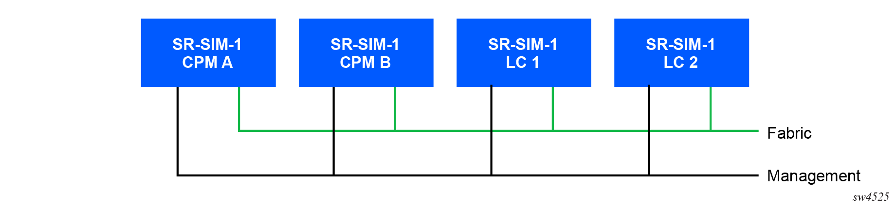
The distributed SR-SIM model allows operators to emulate chassis-based systems. Routers emulated in distributed mode require one container per linecard, with each container being specifically identified as supporting control plane processing (CPM) or datapath functions (IOM or XCM). For example, a system comprising two CPMs and two linecards requires four containers to be created.
A distributed SR-SIM
is created when the configured chassis type is anything other than the
sr-1, sr-1s, ixr-r6,
ixr-ec, ixr-e2, or ixr-e2c
chassis type.
Management interfaces
Distributed SR-SIM systems provide one management interface per CPM. The management
interface is automatically assigned an IPv4 address by the container
management system if it is not explicitly set using the environment variable
NOKIA_SROS_ADDRESS_IPV4_ACTIVE.
Linecard containers (excluding CPM) should have a management interface attached to the container. However, any dynamically or statically assigned management IP addresses are not used by those containers.
Fabric interfaces
The MTU of interfaces associated with SR-SIM internal fabric interfaces must be set to 9000 bytes. Packets sent over the fabric by each IOM/XCM or CPM are Ethernet encapsulated (without 802.1Q VLAN tags), and frames with a multicast or broadcast destination MAC address must be delivered to all containers of the SR-SIM instance.