Interfaces
On the SR Linux, an interface is any physical or logical port through which packets can be sent to or received from other devices. The SR Linux supports the following interface types:
-
Loopback
A loopback interface is a virtual interface that is always up, providing a stable source or destination from which packets can always be originated or received. The SR Linux supports up to 256 loopback interfaces system-wide, across all network-instances. Loopback interfaces are named
loN, where N is 0 to 255. -
System
The system interface is a type of loopback interface that has characteristics that do not apply to regular loopback interfaces:
-
The system interface can be bound to the default network-instance only.
-
The system interface does not support multiple IPv4 addresses or multiple IPv6 addresses.
-
The system interface cannot be administratively disabled. Once configured, it is always up.
The SR Linux supports a single system interface named
system0. When the system interface is bound to the default network-instance, and an IPv4 address is configured for it, the IPv4 address is the default local address for multi-hop BGP sessions to IPv4 neighbors established by the default network-instance, and it is the default IPv4 source address for IPv4 VXLAN tunnels established by the default network-instance. The same functionality applies with respect to IPv6 addresses / IPv6 BGP neighbors / IPv6 VXLAN tunnels. -
-
Network
Network interfaces carry transit traffic, as well as originate and terminate control plane traffic and in-band management traffic.
The physical ports in line cards installed in the SR Linux are network interfaces. A typical line card has a number of front-panel cages, each accepting a pluggable transceiver. Each transceiver may support a single channel or multiple channels, supporting one Ethernet port or multiple Ethernet ports, depending on the transceiver type and its breakout options.
In the SR Linux CLI, each network interface has a name that indicates its type and its location in the chassis. The location is specified with a combination of slot number and port number, using the following formats:
ethernet-slot/portFor example, interface
ethernet-2/1refers to the line card in slot 2 of the SR Linux chassis, and port 1 on that line card. -
Management
Management interfaces are used for out-of-band management traffic. The SR Linux supports a single management interface named
mgmt0.The
mgmt0interface supports the same functionality and defaults as a network interface, except for the following:-
Packets sent and received on the
mgmt0interface are processed completely in software. -
The
mgmt0interface does not support multiple output queues, so there is no output traffic differentiation based on forwarding class. -
The
mgmt0interface does not support pluggable optics. It is a fixed 10/100/1000-BaseT copper port.
-
-
Integrated routing and bridging (IRB)
IRB interfaces enable inter-subnet forwarding. Network instances of type mac-vrf are associated with a network instance of type ip-vrf via an IRB interface.
IRB interfaces are named
irbN, where N is 0 to 255. See IRB interfaces.
On the SR Linux, each loopback, network, management, and IRB interface can be subdivided into one or more subinterfaces. See Subinterfaces.
Linux interface naming conventions
Every type of SR Linux interface has an underlying interface in the Linux OS. These interfaces have names that adhere to Linux restrictions (maximum 15 characters and no slashes). The Linux interface name formats are as follows:
Loopback interfaces:
loN, where N is 0 to 255; for example,lo0Network interfaces:
eslot-port-subinterface; for example,e4-2-1Management interface:
mgmt0System interface:
system0LAG interface:
lagNIRB interface:
irbN
Basic interface configuration
The following example shows a configuration for interface basic parameters, including administratively enabling the interface, specifying a description, and setting the MTU. The settings apply to any subinterfaces on the port, unless overridden in the subinterface configuration.
--{ * candidate shared default }--[  ]--
# info interface ethernet-1/2
 interface ethernet-1/2
    description Sample_interface_config
    admin-state enable
    mtu 1500
Subinterfaces
On the SR Linux, each loopback, network, management, and IRB interface can be subdivided into one or more subinterfaces. A subinterface is a logical channel within its parent interface.
Traffic belonging to one subinterface can be distinguished from traffic belonging to other subinterfaces of the same port using encapsulation methods such as 802.1Q VLAN tags.
While each port can be considered a shared resource of the router that is usable by all network-instances, a subinterface can only be associated with one network-instance at a time. To move a subinterface from one network-instance to another, you must disassociate it from the first network-instance before associating it with the second network-instance. See Network-instances.
You can configure ACL policies to filter IPv4 and IPv6 packets entering or leaving a subinterface. See Access control lists.
The SR Linux supports policies for assigning traffic on a subinterface to forwarding classes or remarking traffic at egress before it leaves the router. DSCP classifier policies map incoming packets to the appropriate forwarding classes, and DSCP rewrite-rule policies mark outgoing packets with an appropriate DSCP value based on the forwarding class.
Routed and bridged subinterfaces
SR Linux subinterfaces can be specified as type routed or bridged:
Routed subinterfaces can be assigned to a network-instance of type mgmt, default, or ip-vrf.
Bridged subinterfaces can be assigned to a network-instance of type mac-vrf.
Routed subinterfaces allow for configuration of IPv4 and IPv6 settings, and bridged subinterfaces allow for configuration of bridge table and VLAN ingress/egress mapping.
Subinterface naming conventions
The CLI name of a subinterface is the name of its parent interface followed by a dot (.) and an index number that is unique within the scope of the parent interface. For example, the subinterface named ethernet-2/1.0 is a subinterface of ethernet-2/1, and it has index number 0.
Each loopback interface (
loN) can only have one subinterface, and the index number can be in the range 0 to 255.Each network interface (
ethernet-slot/port) where the vlan-tagging parameter is set to false can have one subinterface, and the index number can be in the range 0 to 9999.Each network interface where the vlan-tagging parameter is set to true can have up to 4096 subinterfaces (up ro 1024 of type routed and 3072 of type bridged) with each subinterface assigned a unique index number in the range 0 to 9999.
The management and system interfaces (
mgmt0andsystem0) can only have one subinterface, with an index number of 0.
The Linux name of a subinterface adheres to Linux restrictions (maximum 15 characters and no slashes). For example, the subinterface named ethernet-2/1.0 has the Linux name e2-1.0.
Basic subinterface configuration
For IPv4 packets to be sourced from a subinterface, the IPv4 address family must be enabled on the subinterface and the subinterface must be configured with an IPv4 address and prefix length that indicates the other IPv4 hosts reachable on the same subnet.
A subinterface can have up to 64 IPv4 prefixes assigned to it. One or more of these can be optionally configured as a primary candidate. Within the set of IPv4 prefixes configured as primary candidates, the lowest IPv4 address that does not fail duplicate address detection is selected as the primary address for the subinterface. The primary address is used by upper layer protocols that need to choose only one IPv4 address from which to source their messages, as well as for information about this interface displayed with the info from state command. If there is no suitable address in the set of IPv4 prefixes configured as primary candidates (or if no IPv4 prefix is configured as primary), a selection is made from the IPv4 prefixes not configured as primary candidates.
For IPv6 packets to be sourced from a subinterface, the IPv6 address family must be enabled on the subinterface, which must be configured with a global unicast IPv6 address and prefix length. The address can be configured statically or obtained from a DHCP server.
A subinterface can have up to 16 global unicast IPv6 addresses and prefixes assigned to it. One or more of these can be optionally configured as a primary candidate. Within the set of IPv6 prefixes configured as primary candidates, the lowest IPv6 address that does not fail duplicate address detection is selected as the primary address for the subinterface. The primary address is used by upper layer protocols that need to choose only one IPv6 address from which to source their messages, as well as for information about this interface displayed with the info from state command. If there is no suitable address in the set of IPv6 prefixes configured as primary candidates (or if no IPv6 prefix is configured as primary), a selection is made from the IPv6 prefixes not configured as primary candidates.
The following example shows basic parameters for a subinterface configuration, including IPv4 and IPv6 addresses and prefix lengths.
The configuration for subinterface 1 administratively enables the subinterface, specifies an ACL policy for input IPv4 traffic, and specifies a DSCP classifier policy that assigns input IPv4 traffic to a queue based on the 6-bit DSCP value in the IP header.
The configuration for subinterface 2 administratively enables the subinterface, and configures multiple IPv4 and IPv6 addresses and prefix lengths. The primary IPv4 address for the subinterface is selected from among the set of IPv4 prefixes configured as primary candidates; the selected IPv4 address is the numerically lowest address that does not fail duplicate address detection. The global unicast IPv6 address for the subinterface is selected from the IPv6 prefix configured as primary. The selected global unicast IPv6 address is the numerically lowest address that does not fail duplicate address detection.
--{ * candidate shared default }--[  ]--
# info interface ethernet-1/2
 interface ethernet-1/2
    description Sample_interface_config
    admin-state enable
    mtu 1500
    subinterface 1 {
        admin-state enable
        ipv4 {
            dhcp-client true {
            }
        }
        ipv6 {
            address 2001:1::192:168:12:1/126 {
            }
        }
        acl {
            input {
                ipv4-filter 101
            }
        }
        qos {
            input {
                classifiers {
                    ipv4-dscp 1
                }
            }
        }
    }
    subinterface 2 {
        admin-state enable
        ipv4 {
            address 192.168.12.1/30 {
                primary
            }
            address 192.168.12.2/30 {
                primary
            }
            address 192.168.12.2/30 {
            }
        }
        ipv6 {
            address 2001:1::192:168:12:2/126 {
                primary
            }
            address 2001:1::192:168:12:3/126 {
            }
        }
    }
Subinterface VLAN configuration
When the vlan-tagging parameter is set to true for a network interface, the interface can accept ethertype 0x8100 frames with one or more VLAN tags. The interface can be configured with up to 4096 subinterfaces, each with a separate index number.
The following example enables VLAN tagging for an interface and configures two subinterfaces. Single-tagged packets received on subinterface ethernet-2/1.1 are encapsulated with VLAN ID 101.
--{ * candidate shared default }--[  ]--
# info interface ethernet-2/1
 interface ethernet-2/1
    admin-state enable
    vlan-tagging true
    subinterface 1 {
        admin-state enable
        ipv4 {
            dhcp-client true {
            }
        }
    }
    subinterface 2 {
        admin-state enable
        ipv4 {
            dhcp-client true {
            }
        }
        vlan {
            encap {
                single-tagged {
                    vlan-id 101
                }
            }
        }
    }
VLAN tag TPID configuration
The 802.1Q VLAN Tag Protocol Identifier (TPID) in the VLAN tag of an Ethernet frame indicates the protocol type of the VLAN tag. This feature allows you to configure the VLAN tag TPID that is used to classify frames as Dot1q on single-tagged interfaces or to push at egress; by default, the value of the VLAN tag TPID is 0x8100.
You can configure the following TPID values for an interface:
TPID_0X8100Default value typically used to identify 802.1Q single-tagged frames.
TPID_0X88A8Typical TPID value for 802.1Q provider bridging or QinQ S-tags.
TPID_0X9100Alternate TPID value for QinQ tags.
TPID_0X9200Alternate TPID value for QinQ tags.
TPID_ANYWildcard that matches any of the generally used TPID values for single- or multi-tagged VLANs. This value is equivalent to matching any of
TPID_0X8100,TPID_0X88A8,TPID_0X9100, orTPID_0x9200at ingress. At egress, if a tag needs to be pushed andTPID_ANYis configured, the default TPID value is used.
-
This feature does not change the behavior of subinterfaces of type
untaggedorany, nor does it change the behavior of interfaces configured withvlan-tagging false. -
On a Dot1q interface, if the configured TPID is (for example)
TPID_0X88A8, the service-delimiting tags have TPID value 0x88a8, so frames received with that TPID may match a subinterface if they come with the appropriate VLAN ID. Frames with any other TPID value only match untagged interfaces or tagged interfaces with VLAN IDanyoruntagged. - Only one TPID value can be configured per interface.
- The TPID pushed at egress is one of the following:
- The configured TPID, if SR Linux is pushing a service-delimiting tag and
the configured TPID is different from
TPID_ANY. - The default TPID of 0x8100, if SR Linux is pushing a service-delimiting
tag and the configured TPID is
TPID_0X8100orTPID_ANY.
- The configured TPID, if SR Linux is pushing a service-delimiting tag and
the configured TPID is different from
- This feature is supported on all interfaces that support VLAN tagging (that is, all interfaces except for loopback, system, management, and IRB).
- For CPU injected packets, the configured interface TPID is used in injected unicast and multicast frames (in the context of the MAC-VRF flood group), so the configured TPID appears in CPM-outgoing Ethernet frames.
- When the TPID is configured on a LAG interface, the configuration is propagated to all LAG members.
- This feature is not supported on interfaces configured in breakout mode.
Configuring the VLAN tag TPID for an interface
The following example configures the TPID_ANY wildcard for an
interface. At ingress, this configuration matches TPID_0X8100,
TPID_0X88A8, TPID_0X9100, or
TPID_0x9200. SR Linux pushes the default TPID of 0x8100 to
egress frames.
--{ candidate shared default }--[ ]--
# info interface ethernet-1/1
interface ethernet-1/1 {
vlan-tagging true
tpid TPID_ANY
subinterface 1 {
vlan {
encap {
single-tagged {
vlan-id 101
}
}
}
}
}Displaying the VLAN tag TPID
Use the show interface detail command to display the VLAN tag TPID for an interface.
--{ candidate shared default }--[ ]--
# show interface ethernet-1/12 detail
==========================================================================
Interface: ethernet-1/12
--------------------------------------------------------------------------
Description : dut2
Oper state : up
Down reason : N/A
Last change : 47m6s ago, 1 flaps since last clear
Speed : 100G
Flow control : Rx is disabled, Tx is disabled
MTU : 9232
VLAN tagging : true
VLAN TPID : 0x8100
Queues : 8 output queues supported, 1 used since the last clear
MAC address : 00:01:02:FF:00:0C
Last stats clear: 47m6s ago
Breakout mode : falseBridged subinterface configuration
Bridged subinterfaces are associated with a mac-vrf network-instance. On mac-vrf network instances, traffic can be classified based on VLAN tagging. Interfaces where VLAN tagging is set to false or true can be used with mac-vrf network instances.
A default subinterface can be specified, which captures untagged and non-explicitly configured VLAN-tagged frames in tagged subinterfaces.
Within a tagged interface, a default subinterface (vlan-id value is set to any) and an untagged subinterface can be configured. This kind of configuration behaves as follows:
The vlan-id any subinterface captures untagged and non-explicitly configured VLAN-tagged frames.
The untagged subinterface captures untagged and packets with tag0 as outermost tag.
When vlan-id any and untagged subinterfaces are configured on the same tagged interface, packets for unconfigured VLANs go to the vlan-id any subinterface, and tag0/untagged packets go to the untagged subinterface.
The vlan-id value can be configured as a specific valid number or with the keyword any, which means any frame that does not hit the vlan-id configured in other subinterfaces of the same interface is classified in this subinterface.
In the following example, the vlan encap untagged setting is enabled for subinterface 1. This setting allows untagged frames to be captured on tagged interfaces.
For subinterface 2, the vlan encap single-tagged vlan-id any setting allows non-configured VLAN IDs and untagged traffic to be classified to this subinterface.
With the vlan encap untagged setting on one subinterface, and the vlan encap single-tagged vlan-id any setting on the other subinterface, traffic enters the appropriate subinterface; that is, traffic for unconfigured VLANs goes to subinterface 2, and tag0/untagged traffic goes to subinterface 1.
--{ candidate shared default }--[ ]--
# info interface ethernet-1/2
interface ethernet-1/2
vlan-tagging true
subinterface 1 {
type bridged
vlan {
encap {
untagged
}
}
subinterface 2 {
type bridged
vlan {
encap {
single-tagged {
vlan-id any
}
IRB interfaces
Integrated routing and bridging (IRB) interfaces enable inter-subnet forwarding. Network instances of type mac-vrf are associated with a network instance of type ip-vrf via an IRB interface.
On SR Linux, IRB interfaces are named irbN, where
N is 0 to 255. Up to 4095 subinterfaces can be defined under an
IRB interface. An ip-vrf network instance can have multiple IRB subinterfaces, while a
mac-vrf network instance can refer to only one IRB subinterface.
IRB subinterfaces are type routed and cannot be configured as any other type.
IRB subinterfaces operate in the same way as other routed subinterfaces, including support for the following:
IPv4 and IPv6 ACLs
DSCP based QoS (input and output classifiers and rewrite rules)
Static routes and BGP (IPv4 and IPv6 families)
IP MTU (with the same range of valid values as Ethernet subinterfaces)
All settings in the subinterface/ipv4 and subinterface/ipv6 containers. For IPv6, the IRB subinterface also gets an IPv6 link local address
BFD
Subinterface statistics
IRB interfaces do not support sFlow or VLAN tagging.
IRB interface configuration
The following example configures an IRB interface. The IRB interface is operationally up when its admin-state is enabled, and its IRB subinterfaces are operationally up when associated with mac-vrf and ip-vrf network instances. At least one IPv4 or IPv6 address must be configured for the IRB subinterface to be operationally up.
--{ candidate shared default }--[ ]--
# info interface irb1
interface irb1 {
description IRB_Interface
admin-state enable
subinterface 1 {
admin-state enable
ipv4 {
address 172.16.1.1/24 {
}
}
}
}
Displaying interface statistics
To display statistics for a specific interface, use the info from state command in candidate or running mode, or the info command in state mode.
--{ candidate shared default }--[ ]--
# info from state interface ethernet-1/1
interface ethernet-1/1 {
admin-state enable
mtu 9232
loopback-mode false
ifindex 54
oper-state down
oper-down-reason lower-layer-down
last-change 2020-06-04T15:06:35.920Z
vlan-tagging
                            false
statistics {
in-octets 0
in-unicast-packets 0
in-broadcast-packets 0
in-multicast-packets 0
in-error-packets 0
in-fcs-error-packets 0
out-octets 0
out-unicast-packets 0
out-broadcast-packets 0
out-multicast-packets 0
out-error-packets 0
carrier-transitions 0
}
traffic-rate {
in-bps 0
out-bps 0
}
transceiver {
admin-state enable
tx-laser true
oper-state up
ddm-events false
forward-error-correction disabled
form-factor QSFP28
ethernet-pmd 100GBASE-SR4
connector-type MPO-1x12
vendor "AVAGO "
vendor-part-number "AFBR-89CDDZ-AL1 "
vendor-revision 01
serial-number "AF1937GN050 "
date-code "190910 "
fault-condition false
temperature {
latest-value 32
}
voltage {
latest-value 3.2809
}
channel 1 {
wavelength 850.00
input-power {
latest-value -33.98
}
output-power {
latest-value 0.26
}
laser-bias-current {
latest-value 7.494
}
}
channel 2 {
wavelength 850.00
input-power {
latest-value -40.00
}
output-power {
latest-value 0.05
}
laser-bias-current {
latest-value 7.494
}
}
channel 3 {
wavelength 850.00
input-power {
latest-value -23.28
}
output-power {
latest-value 0.02
}
laser-bias-current {
latest-value 7.494
}
}
channel 4 {
wavelength 850.00
input-power {
latest-value -40.00
}
output-power {
latest-value 0.24
}
laser-bias-current {
latest-value 7.494
}
}
}
ethernet {
port-speed 100G
hw-mac-address 68:AB:09:A2:71:B0
flow-control {
receive false
}
statistics {
in-mac-pause-frames 0
in-oversize-frames 0
in-jabber-frames 0
in-fragment-frames 0
in-crc-error-frames 0
out-mac-pause-frames 0
in-64b-frames 0
in-65b-to-127b-frames 0
in-128b-to-255b-frames 0
in-256b-to-511b-frames 0
in-512b-to-1023b-frames 0
in-1024b-to-1518b-frames 0
in-1519b-or-longer-frames 0
out-64b-frames 0
out-65b-to-127b-frames 0
out-128b-to-255b-frames 0
out-256b-to-511b-frames 0
out-512b-to-1023b-frames 0
out-1024b-to-1518b-frames 0
out-1519b-or-longer-frames 0
}
}
sflow {
admin-state enable
}
qos {
output {
unicast-queue 0 {
queue-parameters {
peak-rate-bps 101370000000
strict-priority true
}
}
unicast-queue 1 {
queue-parameters {
peak-rate-bps 101370000000
strict-priority true
}
}
unicast-queue 2 {
queue-parameters {
peak-rate-bps 101370000000
strict-priority true
}
}
unicast-queue 3 {
queue-parameters {
peak-rate-bps 101370000000
strict-priority true
}
}
unicast-queue 4 {
queue-parameters {
peak-rate-bps 101370000000
strict-priority true
}
}
unicast-queue 5 {
queue-parameters {
peak-rate-bps 101370000000
strict-priority true
}
}
unicast-queue 6 {
queue-parameters {
peak-rate-bps 101370000000
strict-priority true
}
}
unicast-queue 7 {
queue-parameters {
peak-rate-bps 101370000000
strict-priority true
}
}
}
}
queue-statistics {
unicast-queue 0 {
virtual-output-queue 1 {
}
virtual-output-queue 2 {
}
virtual-output-queue 3 {
}
virtual-output-queue 4 {
}
}
unicast-queue 1 {
virtual-output-queue 1 {
}
virtual-output-queue 2 {
}
virtual-output-queue 3 {
}
virtual-output-queue 4 {
}
}
unicast-queue 2 {
virtual-output-queue 1 {
}
virtual-output-queue 2 {
}
virtual-output-queue 3 {
}
virtual-output-queue 4 {
}
}
unicast-queue 3 {
virtual-output-queue 1 {
}
virtual-output-queue 2 {
}
virtual-output-queue 3 {
}
virtual-output-queue 4 {
}
}
unicast-queue 4 {
virtual-output-queue 1 {
}
virtual-output-queue 2 {
}
virtual-output-queue 3 {
}
virtual-output-queue 4 {
}
}
unicast-queue 5 {
virtual-output-queue 1 {
}
virtual-output-queue 2 {
}
virtual-output-queue 3 {
}
virtual-output-queue 4 {
}
}
unicast-queue 6 {
virtual-output-queue 1 {
}
virtual-output-queue 2 {
}
virtual-output-queue 3 {
}
virtual-output-queue 4 {
}
}
unicast-queue 7 {
virtual-output-queue 1 {
}
virtual-output-queue 2 {
}
virtual-output-queue 3 {
}
virtual-output-queue 4 {
}
}
multicast-queue 0 {
}
multicast-queue 1 {
}
multicast-queue 2 {
}
multicast-queue 3 {
}
multicast-queue 4 {
}
multicast-queue 5 {
}
multicast-queue 6 {
}
multicast-queue 7 {
}
}
}
Clearing interface statistics
You can clear the statistics counters for a specified interface.
# tools interface ethernet-1/1 statistics clear
/interface[name=ethernet-1/1]:
    interface ethernet-1/1 statistics cleared
To clear queue statistics for an interface:
# tools interface ethernet-1/1 statistics queue-statistics clear
To clear statistics for a specified queue on an interface:
# tools interface ethernet-1/1 statistics queue-statistics multicast-queue 0 clear
Displaying subinterface statistics
To display statistics for a specific subinterface, enter the context for the subinterface and use the info from state command.
--{ candidate shared default }--[  ]--
# interface ethernet-1/2
--{ candidate shared default }--[ interface ethernet-1/2 ]--
# subinterface 1
--{ candidate shared default }--[ interface ethernet-1/2 subinterface 1 ]--
# info from state
    admin-state enable
    ip-mtu 1500
    ifindex 32769
    oper-state up
    last-change 2019-09-30T16:39:29.725Z
    ipv4 {
        allow-directed-broadcast false
        address 192.168.12.2/30 {
            origin static
        }
        arp {
            timeout 14400
            neighbor 192.168.12.1 {
                link-layer-address 00:01:01:FF:00:01
                origin dynamic
                expiration-time 2019-09-30T20:39:30.591Z
            }
        }
    }
    ipv6 {
        address 2001:1::192:168:12:2/126 {
            origin static
            status preferred
        }
        address fe80::201:3ff:feff:1/64 {
            origin link-layer
            status preferred
        }
        neighbor-discovery {
            dup-addr-detect true
            reachable-time 30
            stale-time 14400
            neighbor 2001:1::192:168:12:1 {
                link-layer-address 00:01:01:FF:00:01
                origin dynamic
                is-router true
                current-state reachable
                next-state-time 2019-09-30T17:26:30.018Z
            }
            neighbor fe80::201:1ff:feff:1 {
                link-layer-address 00:01:01:FF:00:01
                origin dynamic
                is-router true
                current-state stale
                next-state-time 2019-09-30T20:40:16.078Z
            }
        }
    }
    statistics {
        in-pkts 564
        in-octets 49394
        in-error-pkts 0
        in-discarded-pkts 0
        in-terminated-pkts 560
        in-terminated-octets 49054
        in-forwarded-pkts 4
        in-forwarded-octets 340
        out-forwarded-pkts 0
        out-forwarded-octets 0
        out-error-pkts 0
        out-discarded-pkts 0
        out-pkts 0
        out-octets 0
    }
    acl {
    }
    qos {
        input {
            classifiers {
                ipv4-dscp default
                ipv6-dscp default
                mpls-tc default
            }
        }
    }
Clearing subinterface statistics
You can clear the statistics counters for a specified subinterface.
# tools interface ethernet-1/1 subinterface 1 statistics clear
/interface[name=ethernet-1/1]/subinterface[index=1]:
    subinterface ethernet-1/1.1 statistics cleared
Displaying interface status
Use the show interface command to display the operational state of configured interfaces.
To display the status of all configured interfaces that have operational state
up and their subinterfaces that also have operational state
up:
--{ running }--[  ]--
# show interface
===================================================================================
ethernet-1/10 is up, speed 100G, type 100GBASE-CR4 CA-L
  ethernet-1/10.1 is up
    Encapsulation: null
    IPv4 addr    : 192.35.1.0/31 (static)
    IPv6 addr    : 2001:192:35:1::/127 (static, preferred)
    IPv6 addr    : fe80::22e0:9cff:fe78:e2ea/64 (link-layer, preferred)
-----------------------------------------------------------------------------------
ethernet-1/21 is up, speed 100G, type 100GBASE-CR4 CA-L
  ethernet-1/21.1 is up
    Encapsulation: null
    IPv4 addr    : 192.45.1.254/31 (static)
    IPv6 addr    : 2001:192:45:1::fe/127 (static, preferred)
    IPv6 addr    : fe80::22e0:9cff:fe78:e2f5/64 (link-layer, preferred)
-----------------------------------------------------------------------------------
ethernet-1/22 is up, speed 100G, type 100GBASE-CR4 CA-L
  ethernet-1/22.1 is up
    Encapsulation: null
    IPv4 addr    : 192.45.3.254/31 (static)
    IPv6 addr    : 2001:192:45:3::fe/127 (static, preferred)
    IPv6 addr    : fe80::22e0:9cff:fe78:e2f6/64 (link-layer, preferred)
-----------------------------------------------------------------------------------
ethernet-1/3 is up, speed 100G, type 100GBASE-CR4 CA-L
  ethernet-1/3.1 is up
    Encapsulation: null
    IPv4 addr    : 192.57.1.1/31 (static)
    IPv6 addr    : 2001:192:57:1::1/127 (static, preferred)
    IPv6 addr    : fe80::22e0:9cff:fe78:e2e3/64 (link-layer, preferred)
-----------------------------------------------------------------------------------
...
===================================================================================
Summary
  3 loopback interfaces configured
  8 ethernet interfaces are up
  1 management interfaces are up
  12 subinterfaces are up
===================================================================================
To display summary information about interfaces that have operational state
up or down:
--{ running }--[  ]--
# show interface brief
+---------------+-------------+------------+-------+--------------+
|     Port      | Admin State | Oper State | Speed |     Type     |
+===============+=============+============+=======+==============+
| ethernet-1/1  | enable      | up         | 100G  | 100GBASE-SR4 |
| ethernet-1/2  | enable      | up         |       | 100GBASE-SR4 |
| ethernet-1/3  | disable     | down       |       |              |
| ethernet-1/4  | disable     | down       |       |              |
| ethernet-1/5  | disable     | down       |       |              |
| ethernet-1/6  | disable     | down       |       |              |
| ethernet-1/7  | disable     | down       |       |              |
+---------------+-------------+------------+-------+--------------+
To display summary information about a specific interface:
--{ running }--[  ]--
# show interface ethernet-1/1 brief
+---------------+-------------+------------+-------+--------------+
|     Port      | Admin State | Oper State | Speed |     Type     |
+===============+=============+============+=======+==============+
| ethernet-1/1  | enable      | up         | 100G  | 100GBASE-SR4 |
+---------------+-------------+------------+-------+--------------+
To display summary information about interfaces and subinterfaces that have
operational state up or down:
--{ running }--[  ]--
# show interface all
===================================================================================
ethernet-1/1 is down, reason port-admin-disabled
-----------------------------------------------------------------------------------
ethernet-1/10 is up, speed 100G, type 100GBASE-CR4 CA-L
  ethernet-1/10.1 is up
    Encapsulation: null
    IPv4 addr    : 192.35.1.0/31 (static)
    IPv6 addr    : 2001:192:35:1::/127 (static, preferred)
    IPv6 addr    : fe80::22e0:9cff:fe78:e2ea/64 (link-layer, preferred)
-----------------------------------------------------------------------------------
ethernet-1/11 is down, reason port-admin-disabled
-----------------------------------------------------------------------------------
ethernet-1/12 is down, reason port-admin-disabled
-----------------------------------------------------------------------------------
...
===================================================================================
Summary
  3 loopback interfaces configured
  8 ethernet interfaces are up
  1 management interfaces are up
  12 subinterfaces are up
===================================================================================
To display summary information about a specific interface and its subinterfaces:
--{ running }--[  ]--
# show interface ethernet-1/21
===================================================================================
ethernet-1/21 is up, speed 100G, type 100GBASE-CR4 CA-L
  ethernet-1/21.1 is up
    Encapsulation: null
    IPv4 addr    : 192.45.1.254/31 (static)
    IPv6 addr    : 2001:192:45:1::fe/127 (static, preferred)
    IPv6 addr    : fe80::22e0:9cff:fe78:e2f5/64 (link-layer, preferred)
===================================================================================
To display details about a specific interface and its subinterfaces:
--{ running }--[  ]--
# show interface ethernet-1/3 detail
===================================================================================
Interface: ethernet-1/3
-----------------------------------------------------------------------------------
  Description     : rifa-difa-1
  Oper state      : up
  Down reason     : N/A
  Last change     : 23m14s ago, No flaps since last clear
  Speed           : 100G
  Flow control    : Rx is disabled, Tx is not supported
  MTU             : 9232
  VLAN tagging    : false
  Queues          : 8 output queues supported, 3 used since the last clear
  MAC address     : 20:E0:9C:78:E2:E3
  Last stats clear: never
-----------------------------------------------------------------------------------
Queue Parameter for ethernet-1/3
-----------------------------------------------------------------------------------
  Queue-id   Scheduling   Weight
-----------------------------------------------------------------------------------
Traffic statistics for ethernet-1/3
-----------------------------------------------------------------------------------
       counter         Rx      Tx
  Octets              14241   11724
  Unicast packets     0       0
  Broadcast packets   0       0
  Multicast packets   52      56
  Errored packets     0       0
  FCS error packets   0       N/A
  MAC pause frames    0       N/A
  Oversize frames     0       N/A
  Jabber frames       0       N/A
  Fragment frames     0       N/A
  CRC errors          0       N/A
-----------------------------------------------------------------------------------
Traffic rate statistics for ethernet-1/3
-----------------------------------------------------------------------------------
    units     Rx   Tx
  kbps rate
-----------------------------------------------------------------------------------
Frame length statistics for ethernet-1/3
-----------------------------------------------------------------------------------
  Frame length(Octets)   Rx   Tx
  64 bytes               0    0
  65-127 bytes           5    8
  128-255 bytes          0    48
  256-511 bytes          47   0
  512-1023 bytes         0    0
  1024-1518 bytes        0    0
  1519+ bytes            0    0
-----------------------------------------------------------------------------------
Transceiver detail for ethernet-1/3
-----------------------------------------------------------------------------------
  Status         : Transceiver is present and operational
  Form factor    : QSFP28
  Channels used  : 4
  Connector type : no-separable-connector
  Vendor         : Mellanox
  Vendor part    : MCP1600-C003
  PMD type       : 100GBASE-CR4 CA-L
  Fault condition: false
  Temperature    : 0
  Voltage        : 0.0000
-----------------------------------------------------------------------------------
Transceiver channel detail for ethernet-1/3
-----------------------------------------------------------------------------------
  Channel No   Rx Power (dBm)   Tx Power (dBm)   Laser Bias current (mA)
  1            -40.00           -40.00           0.000
  2            -40.00           -40.00           0.000
  3            -40.00           -40.00           0.000
  4            -40.00           -40.00           0.000
===================================================================================
  Subinterface: ethernet-1/3.1
-----------------------------------------------------------------------------------
  Oper state      : up
  Down reason     : N/A
  Last change     : 23m14s ago
  Encapsulation   : null
  IP MTU          : 9000
  Last stats clear: never
  IPv4 addr       : 192.57.1.1/31 (static)
  IPv6 addr       : 2001:192:57:1::1/127 (static, preferred)
  IPv6 addr       : fe80::22e0:9cff:fe78:e2e3/64 (link-layer, preferred)
-----------------------------------------------------------------------------------
ARP/ND summary for ethernet-1/3.1
-----------------------------------------------------------------------------------
  IPv4 ARP entries : 0 static, 0 dynamic
  IPv6 ND  entries : 0 static, 0 dynamic
-----------------------------------------------------------------------------------
QOS Policies applied to ethernet-1/3.1
-----------------------------------------------------------------------------------
        Summary            In      Out
  IPv4 DSCP classifier   default
  IPv6 DSCP classifier   default
  IPv4 DSCP rewrite                none
  IPv6 DSCP rewrite                none
-----------------------------------------------------------------------------------
Traffic statistics for ethernet-1/3.1
-----------------------------------------------------------------------------------
     Statistics        Rx     Tx
  Packets             52      8
  Octets              14241   828
  Errored packets     0       0
  Discarded packets   2       0
  Forwarded packets   0       0
  Forwarded octets    0       0
  CPM packets         50      8
  CPM octets          14033   828
===================================================================================
To display information about egress queues and Virtual Output Queues (VOQs) for a specific interface and its subinterfaces:
# show interface ethernet-1/1 queue-statistics
===================================================================================
Interface: ethernet-1/1
-----------------------------------------------------------------------------------
  Description     : <None>
  Oper state      : down
  Down reason     : lower-layer-down
  Last change     : 4d14h50m28s ago, No flaps since last clear
  Speed           : 100G
  Flow control    : Rx is disabled, Tx is not supported
  Loopback mode   : false
  MTU             : 9232
  VLAN tagging    : false
  Queues          : 8 output queues supported, 0 used since the last clear
  MAC address     : 68:AB:09:A2:71:B0
  Last stats clear: never
-----------------------------------------------------------------------------------
Queue Parameter for for ethernet-1/1
-----------------------------------------------------------------------------------
  Queue-id   Scheduling   Weight   PIR %    PIR (kbps)
  0          SP           -        100     98994140.625
  1          SP           -        100     98994140.625
  2          SP           -        100     98994140.625
  3          SP           -        100     98994140.625
  4          SP           -        100     98994140.625
  5          SP           -        100     98994140.625
  6          SP           -        100     98994140.625
  7          SP           -        100     98994140.625
-----------------------------------------------------------------------------------
Queue statistics for interface ethernet-1/1, Queue 0 (fc0 traffic)
-----------------------------------------------------------------------------------
           Name            Fwd-Octets   Fwd-Pkts   Drop-Octets   Drop-Pkts
  Unicast Egress queue     0            0          0             0
  VOQ 1                    0            0          0             0
  VOQ 2                    0            0          0             0
  VOQ 3                    0            0          0             0
  VOQ 4                    0            0          0             0
  Multicast Egress queue   0            0          0             0
-----------------------------------------------------------------------------------
Queue statistics for interface ethernet-1/1, Queue 1 (fc1 traffic)
-----------------------------------------------------------------------------------
           Name            Fwd-Octets   Fwd-Pkts   Drop-Octets   Drop-Pkts
  Unicast Egress queue     0            0          0             0
  VOQ 1                    0            0          0             0
  VOQ 2                    0            0          0             0
  VOQ 3                    0            0          0             0
  VOQ 4                    0            0          0             0
  Multicast Egress queue   0            0          0             0
-----------------------------------------------------------------------------------
Queue statistics for interface ethernet-1/1, Queue 2 (fc2 traffic)
-----------------------------------------------------------------------------------
           Name            Fwd-Octets   Fwd-Pkts   Drop-Octets   Drop-Pkts
  Unicast Egress queue     0            0          0             0
  VOQ 1                    0            0          0             0
  VOQ 2                    0            0          0             0
  VOQ 3                    0            0          0             0
  VOQ 4                    0            0          0             0
  Multicast Egress queue   0            0          0             0
-----------------------------------------------------------------------------------
Queue statistics for interface ethernet-1/1, Queue 3 (fc3 traffic)
-----------------------------------------------------------------------------------
           Name            Fwd-Octets   Fwd-Pkts   Drop-Octets   Drop-Pkts
  Unicast Egress queue     0            0          0             0
  VOQ 1                    0            0          0             0
  VOQ 2                    0            0          0             0
  VOQ 3                    0            0          0             0
  VOQ 4                    0            0          0             0
  Multicast Egress queue   0            0          0             0
-----------------------------------------------------------------------------------
Queue statistics for interface ethernet-1/1, Queue 4 (fc4 traffic)
-----------------------------------------------------------------------------------
           Name            Fwd-Octets   Fwd-Pkts   Drop-Octets   Drop-Pkts
  Unicast Egress queue     0            0          0             0
  VOQ 1                    0            0          0             0
  VOQ 2                    0            0          0             0
  VOQ 3                    0            0          0             0
  VOQ 4                    0            0          0             0
  Multicast Egress queue   0            0          0             0
-----------------------------------------------------------------------------------
Queue statistics for interface ethernet-1/1, Queue 5 (fc5 traffic)
-----------------------------------------------------------------------------------
           Name            Fwd-Octets   Fwd-Pkts   Drop-Octets   Drop-Pkts
  Unicast Egress queue     0            0          0             0
  VOQ 1                    0            0          0             0
  VOQ 2                    0            0          0             0
  VOQ 3                    0            0          0             0
  VOQ 4                    0            0          0             0
  Multicast Egress queue   0            0          0             0
-----------------------------------------------------------------------------------
Queue statistics for interface ethernet-1/1, Queue 6 (fc6 traffic)
-----------------------------------------------------------------------------------
           Name            Fwd-Octets   Fwd-Pkts   Drop-Octets   Drop-Pkts
  Unicast Egress queue     0            0          0             0
  VOQ 1                    0            0          0             0
  VOQ 2                    0            0          0             0
  VOQ 3                    0            0          0             0
  VOQ 4                    0            0          0             0
  Multicast Egress queue   0            0          0             0
-----------------------------------------------------------------------------------
Queue statistics for interface ethernet-1/1, Queue 7 (fc7 traffic)
-----------------------------------------------------------------------------------
           Name            Fwd-Octets   Fwd-Pkts   Drop-Octets   Drop-Pkts
  Unicast Egress queue     0            0          0             0
  VOQ 1                    0            0          0             0
  VOQ 2                    0            0          0             0
  VOQ 3                    0            0          0             0
  VOQ 4                    0            0          0             0
  Multicast Egress queue   0            0          0             0
===================================================================================
LAG
A Link Aggregation Group (LAG), based on the IEEE 802.1ax standard (formerly 802.3ad), increases the bandwidth available between two network devices, depending on the number of links installed. A LAG also provides redundancy if one or more links participating in the LAG fail. All physical links in a LAG combine to form one logical interface.
Packet sequencing is maintained for individual sessions. The hashing algorithm deployed by SR Linux is based on the type of traffic transported to ensure that all traffic in a flow remains in sequence, while providing effective load sharing across the links in the LAG.
LAGs can be either statically configured, or formed dynamically with Link Aggregation Control Protocol (LACP). Load sharing is executed in hardware, which provides line rate forwarding for all port types. A LAG can consist of ports of the same speed, as well as ports of mixed speed; however, the active links would be only those whose port speed matches the configured member-speed parameter for the LAG instance.
Min-link threshold
SR Linux supports configuring a min-link threshold for a LAG, which sets the minimum number of member links that must be active in order for the LAG to be operationally up. If the number of active links falls below this threshold, the entire LAG is brought operationally down.
If the min-link threshold is crossed, the active member links are maintained, including continuing to run LACP on links where it is configured, but the LAG is held out of forwarding state. When the number of active links reaches or exceeds the min-link threshold, the LAG is brought back up operationally.
LACP
LACP, defined by the IEEE 802.3ad standard, specifies a method for two devices to establish and maintain LAGs. When LACP is enabled, SR Linux can automatically associate LACP-compatible ports into a LAG. All non-failing links in a LAG are active, and traffic is load-balanced across the active links.
When LACP is enabled, LACP changes are visible through traps and log messages logged against the LAG.
LACP fallback
LACP fallback allows one or more designated links of an LACP controlled LAG to go into forwarding mode if LACP is not yet operational after a configured timeout period.
SR Linux supports LACP fallback in static mode. In static mode, a single designated LAG member goes into forwarding mode if LACP is not operational after the timeout period.
LACP fallback is configured by selecting the mode and fallback timeout (seconds). If the LAG receives no PDUs and the timeout period expires, the configured fallback mode is enabled. If any member link in the LAG receives a PDU, the fallback mode is immediately disabled.
LAG configuration
To configure a LAG, you specify LAG parameters within the context of a LAG interface, then associate Ethernet interfaces with the LAG interface.
The MAC address of the LAG should be a unique value taken from the chassis MAC address pool.
Member links in the LAG can be associated statically or dynamically.
Static links are explicitly associated with the LAG within the configuration of the LAG instance.
Dynamic links are associated with the LAG using LACP.
A LAG instance can consist of static links only or dynamic links only.
If an Ethernet interface is associated with a LAG interface, the following parameters must be the same for all associated Ethernet ports:
flow-control
port-speed
aggregate-id
The following example shows the configuration for a LAG consisting of three member links.
--{ * candidate shared default }--[  ]--
# info interface *
    interface ethernet-1/1 {
        admin-state enable
        ethernet {
            aggregate-id lag1
        }
    }
    interface ethernet-1/2 {
        admin-state enable
        ethernet {
            aggregate-id lag1
        }
    }
    interface ethernet-1/3 {
        admin-state enable
        ethernet {
            aggregate-id lag1
        }
    }
    interface lag1 {
        subinterface 1 {
            admin-state enable
        }
        lag {
            lag-type static
            min-links 2
        }
    }
Configuring the min-link threshold
The min-link threshold specifies the minimum number of member links that must be active in order for the LAG to be operationally up. If the number of active links falls below this threshold, the entire LAG is brought operationally down.
The following example configures the min-link threshold for a LAG to be 4. If the number of active links in the LAG drops below 4, the LAG is taken operationally down.
--{ * candidate shared default }--[  ]--
# info interface lag1
    interface lag1 {
        lag {
            min-links 4
        }
    }
After the LAG has been taken operationally down because of crossing the min-link threshold, if the number active links in the LAG subsequently reaches 4 or higher, the LAG is brought operationally up. The default for the min-link threshold is 0 (disabled).
Configuring LACP and LACP fallback
When LACP is enabled, SR Linux can automatically associate LACP-compatible ports into
a LAG. LACP should be configured in ACTIVE mode only if LACP
Fallback is also configured.
The following example configures LACP to run on an interface, which can dynamically become a member of a LAG:
--{ * candidate shared default }--[  ]--
# info interface ethernet-1/1 lag
    interface ethernet-1/1 {
        lag {
            lag-type lacp
            min-links 1
            member-speed 100G
            lacp-fallback-mode static
            lacp-fallback-timeout 4
            lacp {
                interval FAST
                lacp-mode ACTIVE
            }
        }
    }
In this example, the LACP interval is set to FAST, which causes LACP messages to be sent every second. The SLOW option for LACP interval causes LACP messages to be sent every 30 seconds.
The following example enables LACP fallback mode for a LAG, which allows a single designated LAG member to go into forwarding mode if LACP is not operational after the timeout period.
--{ * candidate shared default }--[  ]--
# info interface ethernet-1/1 lag
    interface ethernet-1/1 {
        lag {
            lacp-fallback-mode static
            lacp-fallback-timeout 60
        }
    }
The LACP fallback timeout range is 4 to 3600 seconds when the LACP interval is FAST, and 90 to 3600 seconds when LACP interval is SLOW.
The following example enables LACP port priority. When LACP fallback is triggered in static mode, one of the member-links goes into a forwarding state that can be influenced using LACP port priority.
--{ * candidate shared default }--[  ]--
# info interface ethernet-1/1 ethernet
    interface ethernet-1/1 {
        ethernet {
            aggregate-id lag1
            lacp-port-priority 1
            port-speed 25G
            hw-mac-address 00:01:02:FF:00:01
        }
    }
Configuring forwarding viability for LAG member links
By default, all interfaces configured in a LAG are capable of forwarding traffic to the other end of the LAG, assuming all other LAG and port attributes allow it (port and LACP state). You can optionally configure individual LAG members to be non-viable for forwarding traffic to the other end of the LAG link.
When a LAG member is configured as non-viable for forwarding traffic, the interface is not used for the transmission of traffic over the LAG, but is still able to process traffic it receives on the associated member link. In addition, Layer 2 protocols such as LLDP, LACP, and micro-BFD continue to be sent and processed over the non-forwarding-viable LAG member.
The following example configures a LAG member to be non-viable for forwarding traffic across a LAG link. The interface can still receive traffic on the LAG link and participate in Layer 2 functions, but does not transmit packets to the other end of the LAG.
--{ candidate shared default }--[  ]--
# info interface ethernet-1/1 ethernet
    interface ethernet-1/1 {
        ethernet {
            aggregate-id lag1
            forwarding-viable false
        }
}Displaying LAG interface statistics
To display statistics for a LAG interface, use the info from state command in candidate or running mode, or the info command in state mode.
# info from state interface lag1 statistics
    interface lag1 {
        statistics {
            in-octets 0
            in-unicast-packets 0
            in-broadcast-packets 0
            in-multicast-packets 0
            in-error-packets 0
            in-fcs-error-packets 0
            out-octets 7168
            out-unicast-packets 0
            out-broadcast-packets 0
            out-multicast-packets 56
            out-error-packets 0
            last-clear 2020-06-09T21:58:40.919Z
        }
    }
Clearing LAG interface statistics
You can clear the statistics counters for a specified LAG interface.
# tools interface lag1 statistics clear
/interface[name=lag1]:
    interface lag1 statistics cleared
To clear statistics for a LAG interface and all member links:
# tools interface lag1 statistics clear include-members
/interface[name=lag1]:
    interface lag1 and all member interfaces statistics cleared
Breakout ports (7220 IXR-D3 only)
On 7220 IXR-D3 systems, the QSFP28 connector ports (ports 1/3-1/33) can operate in breakout mode. Each QSFP28 connector port operating in breakout mode can have four breakout ports configured, each operating at 25G.
To enable breakout ports, you enable breakout mode for an interface and configure breakout ports for the interface. Breakout ports are named using the following format:
ethernet-slot/port/breakout-port
For example, if interface ethernet 1/3 is enabled for breakout mode, its breakout ports are named as follows:
ethernet 1/3/1ethernet 1/3/2ethernet 1/3/3ethernet 1/3/4
When an interface is operating in breakout mode, it is considered a breakout connector, and not an Ethernet port. Some features that are configurable on an Ethernet port do not apply to a breakout connector. The following parameters cannot be configured on an interface operating as a breakout connector:
mtuloopback-modeaggregate-idauto-negotiateduplex-modeflow-control receiveflow-control transmitlacp-port-priorityport-speedstandby-signalingreload-delayhold-timestorm-controlvlan-taggingsubinterfacelagqossflowtransceiver
When the admin-state parameter for a breakout connector is set to disable, it causes its breakout ports to be shut down. In this case, the output from the info from state command lists the oper-down-reason for the breakout ports as connector-down.
The port-speed setting is not configurable for a breakout port. The speed of the breakout port is determined by the channel-speed setting for the breakout connector.
Note the following when configuring the transceiver parameter for a breakout port:
The tx-laser setting affects only the individual breakout port. If the installed transceiver supports per-channel disabling of the TX laser then configuring
tx-laser = falsecauses the state of the breakout port to be oper-down.If the installed transceiver does not support per-channel disabling of the TX laser, then the state of the breakout port remains oper-up and info from state displays
tx-laser=true.If
ddm-events = trueis configured for any breakout port, then the system generates warning logs for temperature and voltage of the overall transceiver/connector.If
ddm-events = falsefor any breakout port, the system suppresses warning logs for input-power, output-power, and laser-bias-current for that specific port/laser.The configured
forward-error-correctionalgorithm applies only to the individual breakout port.
Configuring breakout mode for an interface
The following is an example of configuring an interface for breakout-mode and enabling breakout ports on the interface.
--{ candidate shared default }--[  ]--
# info interface ethernet-1/3*
    interface ethernet-1/3 {
        admin-state enable
        description "Breakout connector"
        breakout-mode {
            num-channels 4
            channel-speed 25G
            }
        }
    }
    interface ethernet-1/3/1 {
        admin-state enable
        description "Breakout port 1"
        subinterface 1 {
            admin-state enable
            ipv4 {
                address 192.168.12.1/30 {
                }
            }
        }
    }
    interface ethernet-1/3/2 {
        admin-state enable
        description "Breakout port 2"
        subinterface 1 {
            admin-state enable
            ipv4 {
                address 192.168.12.2/30 {
                }
            }
        }
    }
    interface ethernet-1/3/3 {
        admin-state enable
        description "Breakout port 3"
        subinterface 1 {
            admin-state enable
            ipv4 {
                address 192.168.12.3/30 {
                }
            }
        }
    }
    interface ethernet-1/3/4 {
        admin-state enable
        description "Breakout port 4"
        subinterface 1 {
            admin-state enable
            ipv4 {
                address 192.168.12.4/30 {
                }
            }
        }
    }
DHCP relay
DHCP relay refers to the router's ability to act as an intermediary between DHCP clients requesting configuration parameters, such as a network address, and DHCP servers when the DHCP clients and DHCP servers are not attached to the same broadcast domain, or do not share the same IPv6 link (in the case of DHCPv6).
SR Linux supports DHCP relay for IRB subinterfaces and Layer 3 subinterfaces. Up to 8 DHCP or DHCPv6 servers are supported. The DHCP relay maximum packet size (including option 82 and vendor-specific options) is capped at 1500 bytes to avoid fragmentation on the Ethernet segment end attached to the DHCP server.
When DHCP relay is enabled for a subinterface, and a DHCP client initiates a request for configuration parameters, the router accepts the DHCP client's request and relays it to the remote DHCP server, which sends back the configuration parameters. The router relays the configuration parameters to the client.
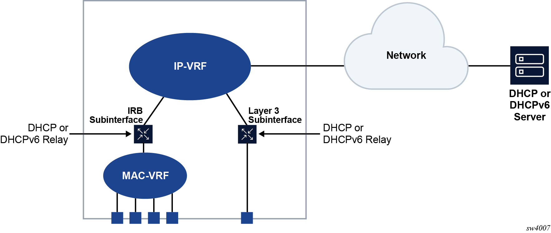
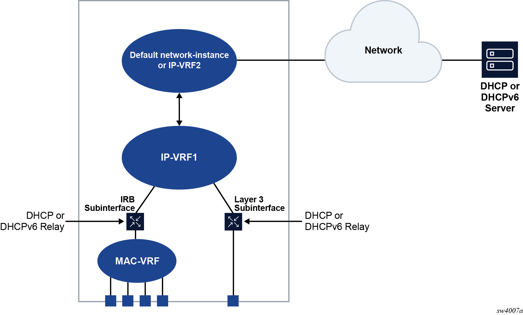
The DHCP server network can be in the same IP-VRF network-instance of the Layer 3 subinterfaces that require DHCP relay (see DHCP relay for IRB and Layer 3 subinterfaces), or it can be in a different IP-VRF network-instance or the default network instance (see DHCP relay using different IP-VRF or default network-instance).
SR Linux supports DHCP relay for IPv4 and IPv6. This guide refers to DHCP for IPv4 as DHCP, and DHCP for IPv6 as DHCPv6.
DHCP relay for IPv4
When DHCP relay is enabled, the router intercepts DHCP broadcast packets and unicasts them to a specified DHCP server for handling. By default, the source address for DHCP packets relayed to the server (GIADDR) is the IP address of the ingress subinterface where the DHCP relay agent is enabled, although a different GIADDR can be specified if necessary.
SR Linux supports DHCP option 82, the Relay Information Option, specified in RFC 3046, which allows the router to append information to DHCP requests relayed to the DHCP server, identifying where the original DHCP request came from. DHCP option 82 includes two sub-options: circuit-id and remote-id.
When configured to do so, SR Linux includes the following information in the circuit-id and remote-id sub-options of DHCP option 82:
For circuit-id, the system_name/VRF_instance/sub-interface_id:vlan_id of the ingress subinterface where the relay agent is enabled that receives the DHCP Discover message from the DHCP client.
For remote-id, the MAC address of the DHCP client.
DHCP message flow for IPv4 address allocation shows an example of the discovery, offer, request, and acknowledgment (DORA) message flow that occurs when DHCP relay assigns an address to a DHCP client.
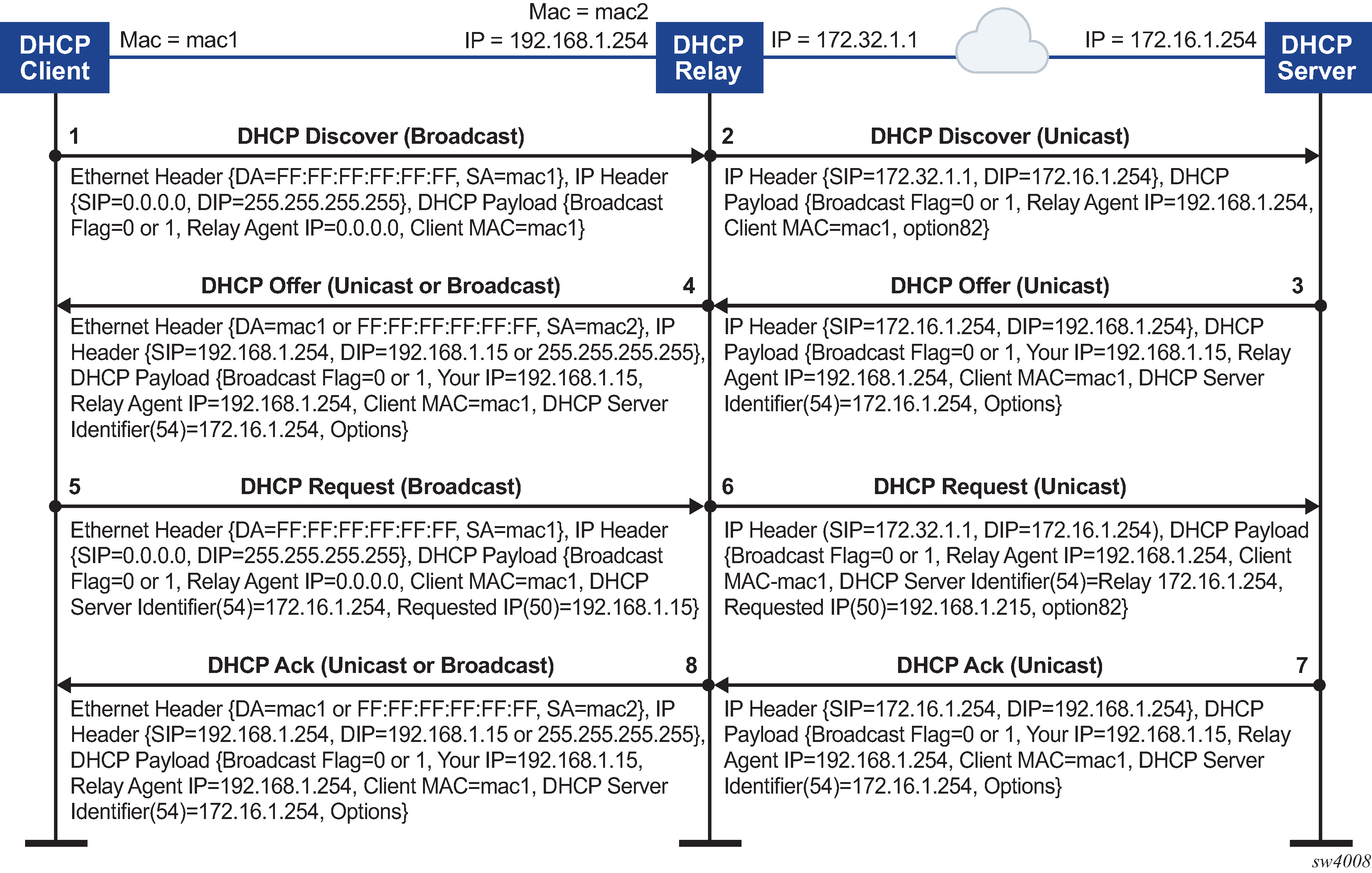
The DORA message flow shown in DHCP message flow for IPv4 address allocation works as follows:
The DHCP client sends a DHCP Discover (broadcast) message with the following values:
DA = FF:FF:FF:FF:FF:FF (broadcast)
SA= client MAC
SIP = 0.0.0.0
DIP = 255.255.255.255
Source UDP port = 68
Destination UDP port = 67
The DHCP payload has the following values:
Broadcast flag = 1 (broadcast) or 0 (unicast)
Relay agent IP = 0.0.0.0
Client MAC = mac1
Parameter request list (option 55) which lists the required items from the DHCP server to be sent along with the IP address like subnet mask, router (gateway), and others
The DHCP relay agent relays the DHCP Discover message toward the DHCP server (unicast). If configured to do so, information is added for the circuit ID and remote ID sub-options in DHCP option 82. The relayed packet is unicast toward the DHCP servers with the following values:
SIP = outgoing interface IP address by default. If the source-address is configured, the relayed packet instead has SIP = configured source-address
UDP source port = 67
UDP destination port = 67
The DHCP payload has the following values:
Broadcast = 1 (broadcast) or 0 (unicast)
Relay agent IP (giaddr) = IP address of the ingress sub-interface where the relay agent is enabled
Client MAC = mac1
Relay agent information (option 82)
The DHCP server assigns an IP address to the DCHP client, based on information in the GIADDR or in option 82, if configured to do so. The DHCP server sends a DHCP Offer message to the DHCP relay agent (unicast). The DHCP Offer message includes the IP address assigned to the DHCP client based on information in the GIADDR or in option 82.
The DHCP Offer packet is unicast with the following values:
SIP = DHCP IP address
DIP = giaddr
UDP source port = 67
UDP destination port = 67
The DHCP payload has the following values:
Broadcast flag = 1 (broadcast) or 0 (unicast).
Your (client) IP = IP address assigned by DHCP server
Agent IP = giaddr
Client MAC = mac1
DHCP identifier = DHCP server IP address
Option 82 (echoed back, and based on DHCP server configuration)
IP address Lease time (option 51)
Subnet mask (option 1)
Router (gateway) (option 3)
Others (DNS, Renewal Time value, Rebinding Time value, and so on)
The DHCP relay agent relays the DHCP Offer message to the DHCP client (either broadcast or unicast, based on the broadcast flag sent by the client).
The DHCP Offer message is relayed from the DHCP server toward the client with the following values:
DA = FF:FF:FF:FF:FF:FF (broadcast) OR Client MAC(unicast)
SIP = sub-interface IP address toward the client where DHCP relay agent is enabled
DIP = 255.255.255.255 (broadcast) OR Your (client) IP address (unicast)
Source UDP port = 67
Destination UDP port = 68
The relay agent relays the DHCP Offer toward the client without option 82. It strips off option 82 if echoed back from DHCP server.
The DHCP payload has the following values:
Broadcast flag = 1 (broadcast) or 0 (unicast).
Your (client) IP = IP address assigned by DHCP server
Agent IP = giaddr
Client MAC = mac1
DHCP identifier = DHCP server IP address
Option 82 (echoed back, and based on DHCP server configuration)
IP address Lease time (option 51)
Subnet mask (option 1)
Router (gateway) (option 3)
Others (DNS, Renewal Time value, Rebinding Time value, and so on.)
The DHCP client sends a DHCP request message (broadcast) with the following values:
DA = FF:FF:FF:FF:FF:FF (broadcast)
SA = client MAC
SIP = 0.0.0.0
DIP = 255.255.255.255
Source UDP port = 68
Destination UDP port = 67
The DHCP payload has the following values:
Broadcast flag = 1 (broadcast) or 0 (unicast).
Relay agent IP = 0.0.0.0
Client MAC = mac1
DHCP server identifier = DHCP server IP address
Requested IP (option 50)
Parameter request list (option 55) that lists the required items from the DHCP server to be sent along with the IP address like subnet mask, router (gateway), and others
The DHCP relay agent relays the DHCP Request message toward the DHCP server (unicast). The relayed packet is unicast toward the DHCP servers, with the following values:
SIP = outgoing interface IP address by default. If source-address is configured, then the relayed packet has SIP = configured source-address.
UDP source port = 67
UDP destination port = 67
The DHCP payload has the following values:
Broadcast flag = 1 (broadcast) or 0 (unicast).
Relay agent IP = giaddr
Client MAC = mac1
DHCP identifier = DHCP server IP address
Requested IP (option 50)
Relay agent Information (option 82) if configured under dhcp-relay
Parameter request list (option 55) that lists the required items from the DHCP server to be sent along with the IP address like subnet mask, router (gateway), and others
Vendor specific option (if configured)
The DHCP server sends a DHCP Ack message to the DHCP relay agent (unicast). The DHCP Ack packet is unicasted with the following values:
SIP = DHCP IP address
DIP = giaddr
UDP source port = 67
UDP destination port = 67
The DHCP payload has the following values:
Broadcast flag, either 1 (broadcast), or 0 (unicast)
Your (client) IP = IP address assigned by DHCP server
Agent IP = giaddr
Client MAC = mac1
DHCP identifier = DHCP server IP address
Option 82 (echoed back and based on DHCP server configuration)
IP address Lease time (option 51)
Subnet mask (option 1)
Router (gateway) (option 3)
Others (DNS, Renewal Time value, Rebinding Time value, and so on.)
Based on the broadcast flag sent by client, the DHCP Offer is relayed from the DHCP servers toward the client with the following values:
DA = FF:FF:FF:FF:FF:FF (broadcast) OR Client MAC(unicast)
SIP = sub-interface IP address toward the client where the DHCP relay agent is enabled
DIP = 255.255.255.255 (broadcast) OR Your (client) IP address (unicast)
Source UDP port = 67
Destination UDP port = 68
The relay agent relays the DHCP Offer toward client without option 82. It strips off option 82 if echoed back from DHCP server.
The DHCP payload has the following values:
Broadcast flag can be either 1 (broadcast), or 0 (unicast)
Your (client) IP = IP address assigned by DHCP server
Agent IP = giaddr
Client MAC = mac1
DHCP Server identifier (option 54) = DHCP server IP address
IP address lease time (option 51)
Subnet mask (option 1)
Router (gateway) (option 3)
Others (DNS, Renewal Time value, Rebinding Time value, and so on.)
When renewing or releasing an address, the DHCP client unicasts the DHCP Request or Release message to the DHCP server without involvement by the DHCP relay agent.
Configuring DHCP relay for IPv4
To configure DHCP relay for a subinterface:
-
Configure the addresses of the DHCP servers.
-
Optionally configure the source address for DHCP messages sent to the servers.
-
Configure whether information is added to the sub-options for DHCP option 82.
The following example configures the DHCP relay agent on a subinterface. The example configures the IP addresses of the remote DHCP servers and specifies the address to be used as the GIADDR in packets sent to the servers
The circuit-id and remote-id options are configured, which causes the DHCP relay agent to include the system_name/VRF_instance/sub-interface_id:vlan_id in the circuit-id sub-option and the DHCP client MAC address in the remote-id sub-option of DHCP option 82.
--{ * candidate shared default }--[  ]--
# info interface ethernet-1/2
 interface ethernet-1/2 {
        subinterface 1 {
            ipv4 {
                address 1.1.4.4/24 {
                }
                dhcp-relay {
                    option [
                           circuit-id
                           remote-id
                    ]
                    source-address 1.1.4.4
                    server [
                        172.16.32.1
                        172.16.64.1
                        192.168.1.1
                    ]
                }
            }
If the DHCP server network is in a different IP-VRF network-instance from the Layer 3 subinterfaces that require DHCP relay (see DHCP relay using different IP-VRF or default network-instance), specify the network-instance in the configuration. For example:
--{ * candidate shared default }--[  ]--
# info interface ethernet-1/2
 interface ethernet-1/2 {
        subinterface 1 {
            ipv4 {
                address 1.1.4.4/24 {
                }
                dhcp-relay {
                    network-instance ipvrf2
                    option [
                           circuit-id
                           remote-id
                    ]
                    source-address 1.1.4.4
                    server [
                        172.16.32.1
                        172.16.64.1
                        192.168.1.1
                    ]
                }
            }
Using the GIADDR as the source address for DHCP Discover/Request packets
By default, the SR Linux uses the IP address of the outgoing interface as the source address for Discover/Request packets sent to the DHCP server. This is not the needed behavior for some configurations, such as a firewall protecting the DHCP server that allows connections from a limited set of IP addresses. You can use the use-gi-addr-as-src-ip-addr parameter to cause the SR Linux to instead use the GIADDR as the source address for Discover/Request packets sent to the DHCP server.
You can optionally configure the GIADDR address using the gi-address parameter. The configured GIADDR address can be a local IP address under the interface where DHCP relay is enabled, any loopback address within the same IP-VRF (if the DHCP server network is in this IP-VRF network-instance), or a loopback address defined in a different IP-VRF/default network-instance (if the DHCP server network is in different IP-VRF/default network-instance).
The following table shows the GIADDR and source address combinations.
|
gi-address parameter |
use-gi-addr-as-src-ipaddr parameter |
GIADDR in relayed packet |
Source IP address in relayed packet |
|---|---|---|---|
|
Not configured (default) |
False (default) |
Primary IP address of interface |
IP address of outgoing interface |
|
Configured |
False (default) |
Configured GIADDR |
IP address of outgoing interface |
|
Configured |
True |
Configured GIADDR |
Configured GIADDR |
|
Not configured (default) |
True |
Primary IP address of interface |
Primary IP address of interface (because it is picked as the GIADDR) |
In the following example, the address specified with the gi-address parameter is used as the source address for Discover/Request packets sent to the DHCP server. If the gi-address parameter is not configured, then the default GIADDR (the primary IP address of the interface) is used.
--{ * candidate shared default }--[  ]--
# info interface ethernet-1/2
 interface ethernet-1/2 {
        subinterface 1 {
        ipv4 {
            address 172.16.1.1/24 {
                primary
            }
            address 172.16.2.1/24 {
            }
            dhcp-relay {
                admin-state enable
                gi-address 172.16.2.1
                use-gi-addr-as-src-ip-addr true
                option [
                    circuit-id
                    remote-id
                ]
                server [
                    1.1.1.1
                    2.2.2.2
                ]
            }
        }
Trusted and untrusted DHCP requests
If the DHCP relay agent receives a DHCP request and the downstream node added option 82 information or set the GIADDR to any value other than 0, the DHCP request is considered to be untrusted. By default, the router drops any untrusted DHCP request and discards the DHCP packets, as described in RFC 3046. SR Linux supports untrusted mode only. The DHCP relay agent discards DHCP packets traveling from the client to server side under the following conditions:
The DHCP packet includes option 82.
The DHCP packet has a GIADDR value that is not 0.
The DHCP relay agent discards DHCP packets traveling from the server to client side under the following conditions:
The circuit-id or remote-id are not enabled on the relay interface, but are present in the packet.
the GIADDR value in the DHCP packet does not match the GIADDR value on the relay interface.
There is no matching entry in the cache.
DHCP relay for IPv6
DHCP relay for IPv6 works similarly to IPv4. However, in DHCPv6, the DHCP Discover, Offer, and Ack messages are replaced by Solicit messages sent by clients, and Advertise and Reply messages sent by servers.
The DHCPv6 relay agent relays messages between clients and remote servers using Relay-Forward (client-to-server) and Relay-Reply (server-to-client) message types. DHCP option 82 is replaced in DHCPv6 by Interface-Id (option 18) and Remote Identifier (option 37), appended by relay agents.
You can optionally configure the DHCPv6 relay agent to include the client's MAC address in Client Link-Layer Address (option 79). This can be useful for dual-stack clients, where a client is using both DHCPv4 and DHCPv6, and the client's MAC address is being used as an identifier for DHCPv4.
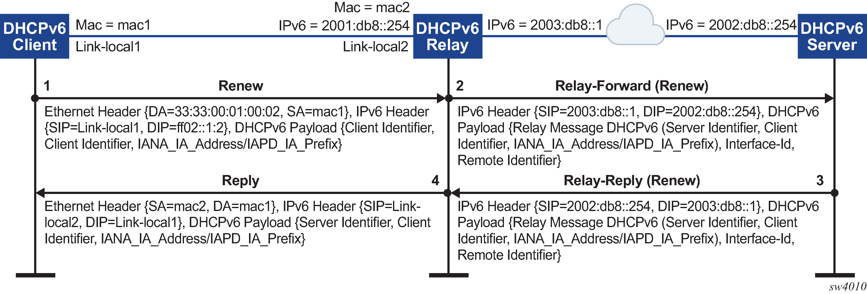
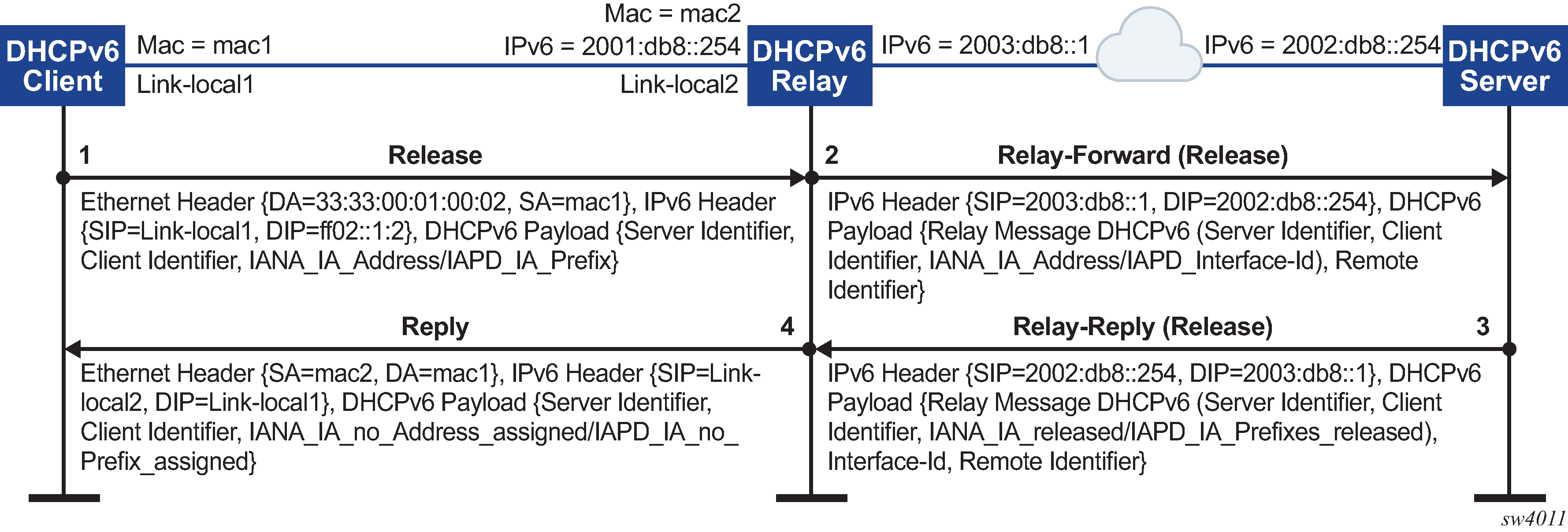
DHCPv6 message flow for IPv6 address allocation shows the DHCPv6 message flow. DHCPv6 renew message flow and DHCPv6 release message flow show the renew and release flows.
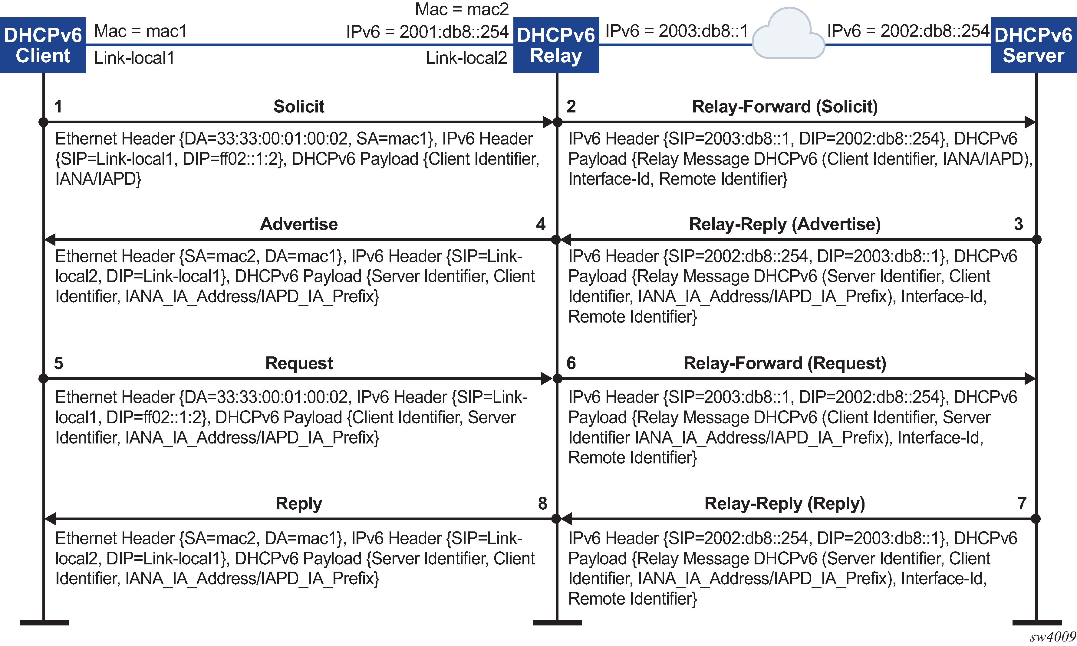
When assigning an address to a DHCP client, DHCP relay for IPv6 works as follows:
The DHCPv6 client uses its link-local address as the source IPv6 address and IPv6 multicast address FF02::1:2 and MAC address 33:33:00:01:00:02 as destination IPv6 address/MAC address respectively for solicit/request messages and with the following UDP values:
source UDP port = 546
destination UDP port = 547
The DHCPv6 relay agent uses a Relay-Forw message to relay the Solicit message toward the DHCPv6 server, using the outbound IPv6 address of the DHCPv6 relay agent as the source IPv6 address and with the following UDP values:
Source UDP port = 547
Destination UDP port = 547
The DHCPv6 server replies to the relay agent an IP address to the DCHP client, based on information in the GIADDR or in option 82, if configured to do so, and with the following UDP values:
Source UDP port = 547
Destination UDP port = 547
The DHCPv6 server replies to the relay agent with destination IPv6 address equal to DHCPv6 (RELAY-FW) source IPv6 address, and the following UDP values:
Source UDP port = 547
Destination UDP port = 547
The DHCP relay agent relays the DHCP Offer message to the DHCP client (either broadcast or unicast, based on the broadcast flag sent by the client).
Configuring DHCP relay for IPv6
To configure DHCP relay for a subinterface for IPv6:
-
Configure the addresses of the DHCPv6 servers.
-
Optionally configure the source IPv6 address for relay-forward messages sent to the servers.
-
Optionally configure whether information is included in the Interface-Id (option 18) and Remote Identifier (option 37) in relay-forward messages.
- Optionally configure whether the MAC address of the DHCP client is included in the Client Link-Layer Address (option 79) in the relay-forward messages.
The following example configures the DHCPv6 relay agent on a subinterface. The example configures the IP addresses of the remote DHCPv6 servers and specifies the address to be used as the source IPv6 address in packets sent to the servers.
The interface-id and remote-id options are configured, which causes the DHCP relay agent to include the system_name/VRF_instance/subinterface_id:vlan_id in Interface-Id (option 18) and the DHCPv6 client MAC address in the Remote Identifier (option 37).
The client-link-layer-address option is configured, which causes the DHCP relay agent to include the DHCPv6 client MAC address in the Client Link-Layer Address (option 79).
--{ * candidate shared default }--[  ]--
# info interface ethernet-1/2
 interface ethernet-1/2 {
        description dut1-dut4-1
        subinterface 1 {
            ipv6 {
                address 2001:db8:101::1/64 {
                    primary
                }
                address 2001:db8:202::1/64 {
                }
                dhcp-relay {
                    admin-state enable
                    source-address 2001:db8:101::1
                    option [
                       interface-id
                       remote-id
                       client-link-layer-address
                    ]
                    server [
                       1::1
                       2::2
                    ]
                }
           }
       }
If the DHCP server network is in a different IP-VRF network-instance from the Layer 3 subinterfaces that require DHCP relay (see DHCP relay using different IP-VRF or default network-instance), specify the network-instance in the configuration. For example:
--{ * candidate shared default }--[  ]--
# info interface ethernet-1/2
 interface ethernet-1/2 {
        description dut1-dut4-1
        subinterface 1 {
            ipv6 {
                address 2001:db8:101::1/64 {
                    primary
                }
                address 2001:db8:202::1/64 {
                }
                dhcp-relay {
                    network-instance ipvrf2
                    admin-state enable
                    source-address 2001:db8:101::1
                    option [
                       interface-id
                       remote-id
                       client-link-layer-address
                    ]
                    server [
                       1::1
                       2::2
                    ]
                }
           }
       }
QoS for DHCP relay
Self-generated DHCP/DHCPv6 packets are mapped into forwarding class 4 (fc4), low drop probability level, and DSCP marking 34 (AF41).
DHCP relay operational down reasons
The DHCP relay agent can enter an operationally down state in the following scenarios:
The DHCP relay admin state is down.
The subinterface under which DHCP relay is configured is operationally down.
All DHCP servers configured within the network instance are unreachable.
The configured GIADDR for DHCP, or source-address for DHCPv6, does not match any of the configured IP addresses under the subinterface where DHCP relay is configured
The IP address is deleted under the subinterface.
Displaying DHCP relay statistics
To display DHCP relay statistics, use the info from state command in candidate or running mode, or the info command in state mode.
IPv4
# info from state interface ethernet-1/16 subinterface 1 ipv4 dhcp-relay statistics
    interface ethernet-1/16 {
        subinterface 1 {
            ipv4 {
                dhcp-relay {
                    statistics {
                        client-packets-received 2
                        client-packets-relayed 2
                        client-packets-discarded 0
                        server-packets-received 2
                        server-packets-relayed 2
                        server-packets-discarded 0
                    }
                }
            }
        }
    }
IPv6
# info from state interface ethernet-1/16 subinterface 1 ipv6 dhcp-relay statistics
    interface ethernet-1/16 {
        subinterface 1 {
            ipv6 {
                dhcp-relay {
                    statistics {
                        client-packets-received 2
                        client-packets-relayed 2
                        client-packets-discarded 0
                        server-packets-received 2
                        server-packets-relayed 2
                        server-packets-discarded 0
                    }
                }
            }
        }
    }
Clearing DHCP relay statistics
You can clear the DHCP relay statistics counters for a specified subinterface.
# tools interface ethernet-1/2 subinterface 1 ipv4 dhcp-relay statistics clear
/interface[name=ethernet-1/2]/subinterface[index=1]:
subinterface ethernet-1/2.1 statistics cleared
DHCP server
For cases where a host requires IPAM (IP Address Management) without an external DHCP server, or where DHCP relay to underlay is not possible, IPAM information can be stored locally on the SR Linux device, which can assign an IP address and other DHCP options to the host using a local DHCP server.
SR Linux supports static IP allocations on both DHCPv4 and DHCPv6 servers. The SR Linux DHCP server can be enabled under regular Layer 3 or IRB subinterfaces. On Layer 3 or IRB subinterfaces, the DHCP server can only be enabled under subinterfaces where DHCP relay is disabled.
When an incoming DHCP Discover or Solicit message is received from a host (DHCP client), and its MAC address matches an entry in the SR Linux DHCP server configuration, the SR Linux DHCP server starts the process of IP address assignment and sends other DHCP options if configured to do so.
For DHCPv4, in addition to IP address allocation, the SR Linux can send the following DHCP options to a host:
- router (option 3) – IPv4 address of the gateway for the DHCP client
- ntp-server (option 4) – List of up to 4 NTP servers for the DHCP client to use
- dns-server (option 6) – List of up to 4 DNS servers for the DHCP client to use
- hostname (option 12) – The hostname for the DHCP client
- domain-name (option 15) – The domain name the client can use when resolving hostnames via DNS
- bootfile-name (option 66) – URL to a provisioning script for the DHCP client to use when booting
- server-id – IP address the DHCP server must match within the network-instance, such as the subinterface primary address or loopback address
For DHCPv6, in addition to IP address allocation, the SR Linux can send a list of up to 4 DNS servers for the DHCP client to use (option 23).
Notes:
- The SR Linux DHCP server supports static IP address allocation only. Dynamic allocation is not supported.
- It is assumed there is no DHCP relay agent between the DHCP client and the SR Linux DHCP server. Relayed frames are not supported.
- For IPv6, DHCP configuration uses MAC-to-IPv6 address binding. The IPv6 address is assigned to the client based on the client's MAC address, not IAID. The client's MAC address is derived from the client identifier. The recommended client identifier type is DUID type DUID-LLT or DUID-LL.
Configuring the DHCP server
To configure the SR Linux DHCP server, you enable it on a subinterface and at the
system dhcp-server level configure DHCPv4 and DHCPv6 options
and static IP allocations for the network-instance where DHCP is required.
The following example enables DHCPv4 and DHCPv6 servers for a subinterface:
--{ * candidate shared default }--[  ]--
# info interface ethernet-1/1 subinterface 1
    interface ethernet-1/1 {
        subinterface 1 {
            admin-state enable
            ipv4 {
                address 192.14.1.4/27 {
                }
                dhcp-server {
                    admin-state enable
                }
            }
            ipv6 {
                address 2001:192:14:1::4/120 {
                }
                dhcpv6-server {
                    admin-state enable
                }
            }
        }
    }
The following example configures DHCPv4 and DHCPv6 options, which are supplied to DHCP clients on the default network-instance:
--{ * candidate shared default }--[  ]--
# info system dhcp-server
    system {
        dhcp-server {
            admin-state enable
            network-instance default {
                dhcpv4 {
                    options {
                        domain-name lan
                        router 192.168.1.1
                        dns-server [
                            192.168.1.53
                            192.168.1.54
                        ]
                        ntp-server [
                            192.168.1.50
                        ]
                    }
                }
                dhcpv6 {
                    options {
                        dns-server [
                            2001:192:14:1::4
                            2001:192:14:1::5
                        ]
                    }
                }
            }
        }
    }
The following example configures static IP allocation settings for an IPv4 host:
--{ * candidate shared default }--[  ]--
# info detail system dhcp-server network-instance default dhcpv4
    system {
        dhcp-server {
            admin-state enable
            network-instance default {
                dhcpv4 {
                    admin-state enable
                    static-allocation {
                        host 00:1D:FE:E0:E9:7C {
                            ip-address 192.168.1.1/24
                            options {
                                router 192.168.1.1
                                dns-server [
                                    192.168.1.53
                                ]
                            }
                        }
                    }
                }
            }
        }
    }
The following example configures static IP allocation settings for an IPv6 host:
--{ * candidate shared default }--[  ]--
# info detail system dhcp-server network-instance default dhcpv6
    system {
        dhcp-server {
            admin-state enable
            network-instance default {
                dhcpv6 {
                    admin-state enable
                    static-allocation {
                        host 92:93:47:30:32:CA {
                            ip-address 2001:1::192:168:12:1/126
                            options {
                                dns-server [
                                    2001:192:14:1::4
                                ]
                            }
                        }
                    }
                }
            }
        }
    }
IPv6 router advertisements
You can configure an IPv6 subinterface to originate Router Advertisement (RA) messages. The following settings can be configured for the RA messages:
Current hop limit to advertise in the RA messages.
IP MTU. Hosts can associate the IP MTU with the link on which the RA messages are received.
Managed configuration flag. When enabled, this setting indicates that hosts should use DHCPv6 to obtain IPv6 addresses.
Other configuration flag. When enabled, this setting indicates that hosts should use DHCPv6 to obtain other configuration information (besides addresses).
The maximum and minimum time between sending router advertisement messages to the all-nodes multicast address.
IPv6 prefix list. Hosts that support Stateless Address Auto-Configuration (SLAAC) can use the IPv6 prefixes in the RA messages to generate IPv6 addresses.
Number of milliseconds advertised for the reachable time and the retransmit time in RA messages, which hosts use for address resolution and the ICMPv6 Neighbor Unreachability Detection algorithm.
Number of seconds advertised as the router lifetime in RA messages. This setting indicates amount of time the advertising router can be used as a default router/gateway.
Configuring IPv6 router advertisements
The following example configures the SR Linux to originate RA messages from an IPv6 subinterface. The RA messages include an IPv6 prefix that SLAAC-enabled clients can use to generate IPv6 addresses.
--{ * candidate shared default }--[  ]--
# info interface ethernet-1/1 subinterface 1 ipv6 router-advertisement
    interface ethernet-1/1 {
        subinterface 1 {
            ipv6 {
                router-advertisement {
                    router-role {
                        admin-state enable
                        prefix 2001:db8:0:b::/64 {
                        }
                    }
                }
            }
        }
    }
IPv6 Router Advertisement guard (RA guard)
IPv6 Router Advertisement guard (IPv6 RA guard) allows you to configure policies that filter out IPv6 RA messages that may be incorrectly or maliciously configured. IPv6 RA messages entering a subinterface where an IPv6 RA guard policy is applied can be accepted or discarded based on match criteria specified in the policy.
IPv6 RA guard is supported on Layer 2 and Layer 3 subinterfaces, which allows unwanted RA messages to be discarded as close to the network edge or server connection as possible. The IPv6 RA guard feature can be configured on 7220 IXR-D1, D2, and D3 systems only.
On IRB interfaces, an IPv6 RA guard policy can be applied to the Layer 2 subinterface, but not on the IRB subinterface.
Ingress ACLs are applied before IPv6 RA guard policies, which may cause RA messages to be discarded before they can be evaluated by an IPv6 RA guard policy
Ingress ACLs are applied before IPv6 RA guard policies, which may cause RA messages to be discarded before they can be evaluated by an IPv6 RA guard policy
The following can be used as match criteria in an IPv6 RA guard policy:
Advertised IPv6 prefix set
Source IPv6 address list or prefix set
RA hop-count limit
Router preference value
Managed configuration flag (M-flag) setting
Other configuration flag (O-flag) setting
An IPv6 RA guard policy can have an action of accept or discard. When an IPv6 RA guard policy is applied to a subinterface, the default action for the subinterface is the opposite of the action specified in the policy. If the policy action is accept, then IPv6 RA packets that do not match the policy are discarded; if the policy action is discard, IPv6 RA packets that do not match the policy are accepted.
To configure IPv6 RA guard, you specify match criteria and an action in an IPv6 RA guard policy, then apply the policy to a subinterface. If an IPv6 RA guard policy is not applied to a subinterface, then IPv6 RA guard is disabled on that subinterface.
Depending on your configuration, it may be more efficient to block IPv6 RA messages on a subinterface using an ACL entry and action, instead of configuring an IPv6 RA guard policy.
Configuring IPv6 RA guard policies
To configure an IPv6 RA guard policy, you specify one or more match criteria and an action of either accept or discard.
The following example configures and IPv6 RA guard policy with an advertised IPv6 prefix set and source IPv6 prefix set as match criteria, and accept as the action.
To be considered a match, all advertised prefixes in the RA message must match the IPv6 prefix set, and the source address of the RA message must match the source IPv6 address prefix set.
--{ * candidate shared default }--[  ]--
# info system ra-guard-policy
    system {
        ra-guard-policy rag1 {
            action accept
            advertise-prefix-set 2001:db8:0:b::/64
            source-prefix-set 2001:1::192:168:11:1/126
        }
    }
The following example configures an IPv6 RA guard policy with no match criteria and action of discard. This policy blocks all RA messages on subinterfaces where it is applied.
--{ * candidate shared default }--[  ]--
# info system ra-guard-policy
    system {
        ra-guard-policy "Discard all" {
            action discard
        }
    }
Applying IPv6 RA guard policies to subinterfaces
To activate IPv6 RA guard, you apply an IPv6 RA guard policy to a subinterface.
The following example applies an IPv6 RA guard policy to a subinterface. This policy (configured in the previous example) causes all IPv6 RA messages received on the subinterface to be discarded.
--{ * candidate shared default }--[  ]--
# info interface ethernet-1/4 subinterface 2 ra-guard
    interface ethernet-1/4 {
        subinterface 2 {
            ra-guard {
                policy "Discard all"
            }
        }
    }
If the subinterface has VLANs configured, you can specify a list of VLANs to which the IPv6 RA guard policy applies. If a VLAN list is specified, the IPv6 RA guard policy applies only to those VLANs, not to any others configured on the subinterface. If VLAN list is not specified, the policy applies to all VLANs on the subinterface.
On a default bridged subinterface, where the vlan encap single-tagged vlan-id
any setting is configured, a VLAN list must be specified with the IPv6
RA guard policy. For example:
--{ * candidate shared default }--[  ]--
# info interface ethernet-1/4 subinterface 2
    interface ethernet-1/4 {
        subinterface 2 {
            admin-state enable
            type bridged
            vlan {
                encap {
                    single-tagged {
                        vlan-id any
                        }
                    }
                }
            }
            ra-guard {
                policy rag1
                vlan-list 10 {
                }
            }
        }
    }
Interface port speed configuration
By default, ports on SR Linux devices operate at the speeds listed in Default and supported port speeds for SR Linux devices. You can optionally configure ports to operate a different speed as long as that speed is supported for the port. On all devices, the Mgmt ports operate at 1G.
On 7220 IXR-D1 systems, it is possible to configure auto-negotiation for the port. See Configuring link auto-negotiation (7220 IXR-D1 only).
SR Linux Device |
Port range |
Default port speed |
Supported port speeds |
|---|---|---|---|
7250 IXR |
IMM ports 1-32 |
100G |
40G, 100G Note: Ports 9-12 cannot operate at different port speeds (some at 40G and others at 100G). The required speed of ports 9-12 is based on the port-speed of the lowest-numbered configured port in this block; if any higher-numbered port in the block is configured with a different port speed that port does not come up. |
IMM ports 33-36 |
100G |
40G, 100G, 400G |
|
7220 IXR-D1 |
Ports 1-48 |
1G |
10M, 100M, 1G |
Ports 49-52 |
10G |
10G |
|
7220 IXR-D2 |
Ports 1-48 |
25G |
1G, 10G, 25G Note: If one port in each consecutive group of 4 ports (1-4, 5-8, and so on) is 25G, the other 3 ports must also be 25G. If one port in each consecutive group of 4 ports is 1G or 10G, the other 3 ports must also be 1G or 10G. |
Ports 49-56 |
100G |
40G, 100G |
|
7220 IXR-D3 |
Ports 1-2 |
10G |
10G |
ethernet-1/[3-34] |
100G |
40G, 100G |
|
ethernet-1/[3-33]/n |
none |
10G, 25G |
|
7220 IXR-H2 |
Ports 1-128 |
100G |
100G |
7220 IXR-H3 |
Ports 1-2 |
10G |
10G |
Ports 3-34 |
400G |
40G, 100G, 400G |
Configuring interface port speed
The following example configures the port speed for an interface.
--{ * candidate shared default }--[  ]--
# info from state interface ethernet-1/1
    interface ethernet-1/1 {
        ethernet {
            port-speed 100G
            }
        }
    }
Configuring link auto-negotiation (7220 IXR-D1 only)
For ports 1-48 on 7220 IXR-D1 systems, you can configure the interface to use auto-negotiation for the speed, duplex, and flow-control settings. Port speed negotiation for RJ-45 ports (7220 IXR-D1 systems) lists how the auto-negotiation setting inter-operates with the port-speed configured for the interface.
|
auto-negotiate parameter setting |
Port speed parameter configured? |
Port speed behavior |
|---|---|---|
|
false |
No |
Bring up the port at the default speed of 1G. |
|
false |
Yes |
Bring up the port at the configured speed of 10M, 100M or 1G if the other side is configured for the same speed; otherwise, the port state is oper-down. |
|
true (default) |
No |
All speeds are advertised as supported, and the actual speed is the highest common value between the two sides. |
|
true (default) |
Yes |
The configured port speed is the only speed advertised. If the port at the other side of the link advertises this speed as well, the link comes up; otherwise it stays down. |
The following example configures auto-negotiation and port speed for a port on a 7220 IXR-D1 system. In this example, a port speed is configured, and the auto-negotiation setting is enabled. The SR Linux advertises the configured port speed to the other end of the link. If the other port also advertises this speed, then the link is established; otherwise, the port state is oper-down.
--{ * candidate shared default }--[  ]--
# info from state interface ethernet-1/1
    interface ethernet-1/1 {
        ethernet {
            auto-negotiate true
            port-speed 100M
            }
        }
    }
Interface hold-timers
You can configure hold-timers that keep an interface operationally enabled or disabled for a specified amount of time following an event that brings the interface up or shuts the interface down.
For example, you can configure a hold-timer that keeps an interface operationally disabled for a period of time following a system reboot, and you can configure a hold-timer that keeps an interface operationally enabled for a period of time after the interface goes down.
The main use for hold-timers is to reduce the number of link transitions and advertise/withdraw messages in networks where there are flapping optics.
You can configure a hold-time up timer and a hold-time down timer for an interface:
-
hold-time up timer
This timer specifies the amount of time an interface is kept operationally disabled following an event that would normally enable it, such as entering the interface admin-state enable command or a system reboot.
The interface remains disabled from the time the event occurs until the hold-time up timer expires. While the hold-time up timer is running, the transceiver is enabled but the system does not consider the interface operationally up until the timer expires.
-
hold-time down timer
This timer specifies the amount of time an interface remains operationally enabled following an event that brings the interface down. When triggered, the hold-time down timer keeps the interface operationally enabled until the timer expires. Entering the interface admin-state disable command does not trigger the hold-time down timer, nor does internal events such as fabric unavailability.
If you manually disable the interface while the hold-time down timer is running, the interface is disabled immediately, and the timer is aborted.
The hold-timers can be set to a value from 1-86,400 seconds. There is no default value; if not configured, no hold-time is considered when an interface changes state.
The hold-timers are available for Ethernet interfaces only, including those that are part of a LAG. You cannot configure a hold-timer for an interface in breakout mode.
The hold-timer does not affect the port LED color, which reflects the physical status of the port; that is, the port LED is green when the hold-time up timer is running, and solid amber when the hold-time down timer is running.
Configuring interface hold timers
To configure hold-timers for an interface, you specify a time value from 1-86,400 seconds for the hold-time up and/or hold-time down timers.
The following example configures a hold-time up and a hold-time down timer for an interface.
In this example, when the interface is enabled, it remains operationally disabled for 200 seconds, until the hold-time up timer expires. When the interface becomes disabled, it remains operationally enabled for 100 seconds, until the hold-time down timer expires.
--{ candidate shared default }--[  ]--
# info interface ethernet-1/1 ethernet
    interface ethernet-1/1 {
        ethernet {
            hold-time {
                up 200
                down 100
            }
        }
    }
When a hold-timer is in effect, you can use the info from state command to display the amount of time remaining. For example:
--{ running }--[  ]--
# info from state interface ethernet-1/1 ethernet hold-time
    interface ethernet-1/1 {
        ethernet {
            hold-time {
                up 200
                down 100
                up-expires 85 seconds from now
            }
        }
    }
In addition, when the hold-time up timer is in effect, the
port-oper-down-reason for the interface is shown as
interface-hold-time-up-active.
Reload-delay timer
After the system boots, the reload-delay timer keeps an interface shut down with the laser off for a configured amount of time until connectivity with the rest of network is established. When applied to an access multi-homed interface (typically an Ethernet Segment interface), this delay can prevent black-holing traffic coming from the multi-homed server or CE.
When a reload-delay timer is configured, the interface port is shut down and the laser is turned off from the time that the system determines the interface state following a reboot or reload of the XDP process, until the number of seconds specified in the reload-delay timer elapse.
The reload-delay timer is only supported on Ethernet interfaces that are not enabled with breakout mode. For a multi-homed LAG interface, the reload-delay timer should be configured on all the interface members. The reload-delay timer can be from 1-86,400 seconds. There is no default value; if not configured for an interface, there is no reload-delay timer.
Only ES interfaces should be configured with a non-zero reload-delay timer. Single-homed interfaces and network interfaces (used to forward VXLAN traffic) should not have a reload-delay timer configured.
The following example sets the reload-delay timer for an interface to 20 seconds. The timer starts following a system reboot or when the IMM is reconnected, and the system determines the interface state. During the timer period, the interface is deactivated and the port laser is inactive.
--{ * candidate shared default }--[  ]--
# info interface ethernet-1/1
    interface ethernet-1/1 {
        admin-state enable
        ethernet {
            reload-delay 20
        }
    }
When the reload-delay timer is running, the port-oper-down-reason for
the port is shown as interface-reload-timer-active. The
reload-delay-expires state indicates the amount of time remaining
until the port becomes active. For example:
--{ running }--[  ]--
# info from state interface ethernet-1/1
    interface ethernet-1/1 {
        description eth_seg_1
        admin-state enable
        mtu 9232
        loopback-mode false
        ifindex 671742
        oper-state down
        oper-down-reason interface-reload-time-active
        last-change "51 seconds ago"
        vlan-tagging true
        ...
        ethernet {
            auto-negotiate false
            lacp-port-priority 32768
            port-speed 100G
            hw-mac-address 00:01:01:FF:00:15
            reload-delay 20
            reload-delay-expires "18 seconds from now"
            flow-control {
                receive false
                transmit false
            }
        }
    }
Configuring the reload-delay timer for an interface
To configure the reload-delay timer for an interface, you specify a timer value from 1-86,400 seconds. The timer starts following a system reboot or when the IMM is reconnected, and the system determines the interface state. During the timer period, the interface is deactivated and the port laser is inactive. You can display information about an active reload-delay timer by entering the info from state command for the interface.
The following example sets the reload-delay timer for an interface to 20 seconds.
--{ * candidate shared default }--[  ]--
# info interface ethernet-1/1
    interface ethernet-1/1 {
        ethernet {
            reload-delay 20
        }
    }
When the reload-delay timer is running, the port-oper-down-reason
for the port is shown as interface-reload-timer-active. The
reload-delay-expires state indicates the amount of time
remaining until the port becomes active. For example:
--{ running }--[  ]--
# info from state interface ethernet-1/1
    interface ethernet-1/1 {
        description eth_seg_1
        admin-state enable
        mtu 9232
        loopback-mode false
        ifindex 671742
        oper-state down
        oper-down-reason interface-reload-time-active
        last-change "51 seconds ago"
        vlan-tagging true
        ...
        ethernet {
            auto-negotiate false
            lacp-port-priority 32768
            port-speed 100G
            hw-mac-address 00:01:01:FF:00:15
            reload-delay 20
            reload-delay-expires "18 seconds from now"
            flow-control {
                receive false
                transmit false
            }
        }
    }