EVPN for Layer 3
This chapter describes the components of EVPN Layer 3 on SR Linux.
EVPN Layer 3 basic configuration
The basic EVPN Layer 3 configuration model builds on the model for EVPN routes described in EVPN for Layer 2 ELAN services, extending it with an additional route type to support inter-subnet forwarding: EVPN IP prefix route (or type 5, RT5).
The EVPN IP prefix route conveys IP prefixes of any length and family (IPv4 or IPv6) that need to be installed in the ip-vrfs of remote leaf nodes. The EVPN Layer 3 configuration model has two modes of operation:
asymmetric IRB
This is a basic mode of operation EVPN Layer 3 using IRB interfaces. The term asymmetric refers to how there are more lookups performed at the ingress leaf than at the egress leaf.
While the asymmetric model allows inter-subnet-forwarding in EVPN-VXLAN networks in a very simple way, it requires the instantiation of all the MAC-VRFs of all the tenant subnets on all the leafs attached to the tenant. Because all the MAC-VRFs of the tenant are instantiated, FDB and ARP entries are consumed for all the hosts in all the leafs of the tenant.
These scale implications may make the symmetric model a better choice for data center deployment.
symmetric IRB
The term symmetric refers to how MAC and IP lookups are needed at ingress, and MAC and IP lookups are performed at egress. As opposed to asymmetric, symmetric IRB implies the same number of lookups at ingress and egress.
SR Linux support for symmetric IRB includes the prefix routing model using RT5s as in RFC 9136, including the interface-less IP-VRF-to-IP-VRF model (EVPN IFL model).
Compared to the asymmetric model, the symmetric model scales better because hosts’ ARP and FDB entries are installed only on the directly attached leafs and not on all the leafs of the tenant.
The following sections show asymmetric and symmetric IFL forwarding configurations.
Asymmetric IRB
The asymmetric IRB model is the basic Layer 3 forwarding model when the IP-VRF (or default network-instance) interfaces are all IRB-based. The asymmetric model assumes that all the subnets of a tenant are local in the IP-VRF/default route table, so there is no need to advertise EVPN RT5 routes.
The following figure shows the asymmetric IRB model for EVPN-VXLAN services. This model is also applicable to EVPN-MPLS services, where VXLAN encapsulation is replaced with MPLS encapsulation for Ethernet frames.
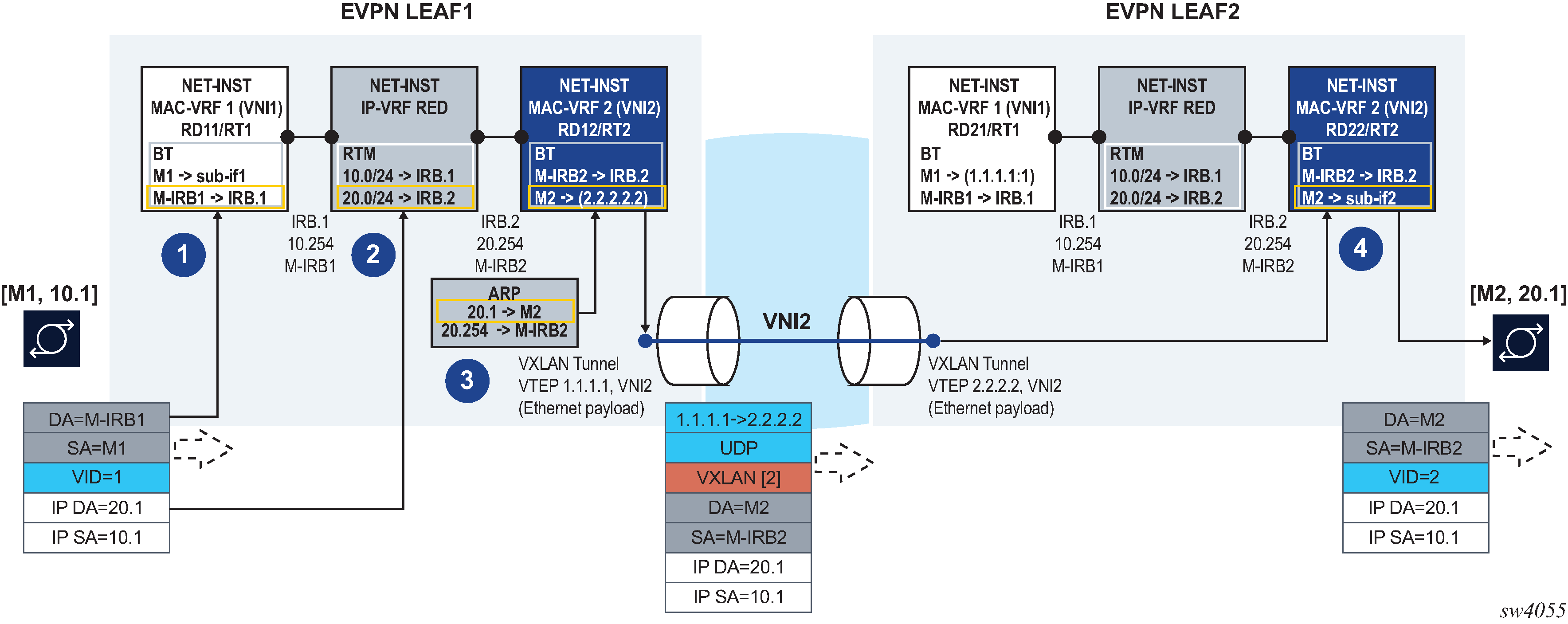
In this example, the host with IP address 10.1 (abbreviation of 10.0.0.1) sends a unicast packet with destination 20.1 (a host in a different subnet and remote leaf). Because the IP DA is in a remote subnet, the MAC DA is resolved to the local default gateway MAC, M-IRB1. The frame is classified for MAC lookup on MAC-VRF 1, and the result is IRB.1, which indicates that an IP DA lookup is required in IP-VRF red.
An IP DA longest-prefix match in the route table yields IRB.2, a local IRB interface, so an ARP and MAC DA lookup are required in the corresponding IRB interface and MAC-VRF bridge table.
The ARP lookup yields M2 on MAC-VRF 2, and the M2 lookup yields the EVPN destination [VTEP:VNI]=[2.2.2.2:2]. For EVPN-MPLS, this destination would be [TEP:label]. The routed packet is encapsulated with the corresponding inner MAC header and VXLAN or MPLS encapsulation before being sent to the wire.
In the asymmetric IRB model, if the ingress leaf routes the traffic via the IRB to a local subnet, and the destination MAC is aliased to multiple leaf nodes in the same ES destination, SR Linux can do load balancing on a per-flow basis.
EVPN Leaf 1 in EVPN-VXLAN Layer 3 asymmetric forwarding has the following configuration:
--{ [FACTORY] + candidate shared default }--[  ]--
# info
    interface ethernet-1/2 {
        admin-state enable
        vlan-tagging true
        subinterface 1 {
            type bridged
            admin-state enable
            vlan {
                encap {
                    single-tagged {
                        vlan-id 1
                    }
                }
            }
        }
    }
    interface irb0 {
        subinterface 1 {
            ipv4 {
                admin-state enable
                address 10.0.0.254/24 {
                    anycast-gw true
                }
            }
            anycast-gw {
            }
        }
        subinterface 2 {
            ipv4 {
                admin-state enable
                address 20.0.0.254/24 {
                    anycast-gw true
                }
            }
            anycast-gw {
            }
        }
    }
    network-instance ip-vrf-red {
        type ip-vrf
        interface irb0.1 {
        }
        interface irb0.2 {
        }
    }
    network-instance mac-vrf-1 {
        type mac-vrf
        admin-state enable
        interface ethernet-1/2.1 {
        }
        interface irb0.1 {
        }
        vxlan-interface vxlan1.1 {
        }
        protocols {
            bgp-evpn {
                bgp-instance 1 {
                    admin-state enable
                    vxlan-interface vxlan1.1
                    evi 1
                }
            }
            bgp-vpn {
            }
        }
    }
    network-instance mac-vrf-2 {
        type mac-vrf
        admin-state enable
        interface irb0.2 {
        }
        vxlan-interface vxlan1.2 {
        }
        protocols {
            bgp-evpn {
                bgp-instance 1 {
                    admin-state enable
                    vxlan-interface vxlan1.2
                    evi 2
                }
            }
            bgp-vpn {
            }
        }
    }
    tunnel-interface vxlan1 {
        vxlan-interface 1 {
            type bridged
            ingress {
                vni 1
            }
        }
        vxlan-interface 2 {
            type bridged
            ingress {
                vni 2
            }
        }
    }
EVPN Leaf 2 in EVPN-VXLAN Layer 3 asymmetric forwarding has the following configuration:
--{ [FACTORY] + candidate shared default }--[  ]--
A:LEAF2# info
    interface ethernet-1/12 {
        admin-state enable
        vlan-tagging true
        subinterface 1 {
            type bridged
            admin-state enable
            vlan {
                encap {
                    single-tagged {
                        vlan-id 2
                    }
                }
            }
        }
    }
    interface irb0 {
        subinterface 1 {
            ipv4 {
                admin-state enable
                address 10.0.0.254/24 {
                    anycast-gw true
                }
            }
            anycast-gw {
            }
        }
        subinterface 2 {
            ipv4 {
                admin-state enable
                address 20.0.0.254/24 {
                    anycast-gw true
                }
            }
            anycast-gw {
            }
        }
    }
    network-instance ip-vrf-red {
        type ip-vrf
        interface irb0.1 {
        }
        interface irb0.2 {
        }
    }
    network-instance mac-vrf-1 {
        type mac-vrf
        admin-state enable
        interface irb0.1 {
        }
        vxlan-interface vxlan1.1 {
        }
        protocols {
            bgp-evpn {
                bgp-instance 1 {
                    admin-state enable
                    vxlan-interface vxlan1.1
                    evi 1
                }
            }
            bgp-vpn {
            }
        }
    }
    network-instance mac-vrf-2 {
        type mac-vrf
        admin-state enable
        interface irb0.2 {
        }
        vxlan-interface vxlan1.2 {
        }
        protocols {
            bgp-evpn {
                bgp-instance 1 {
                    admin-state enable
                    vxlan-interface vxlan1.2
                    evi 2
                }
            }
            bgp-vpn {
            }
        }
    }
    tunnel-interface vxlan1 {
        vxlan-interface 1 {
            type bridged
            ingress {
                vni 1
            }
        }
        vxlan-interface 2 {
            type bridged
            ingress {
                vni 2
            }
        }
    }
mac-vrf-1 on Leaf 1 would have the following
configuration:--{ [FACTORY] + candidate shared default }--[ ]--
# info
<snip>
network-instance mac-vrf-1 {
type mac-vrf
admin-state enable
interface ethernet-1/2.1 {
}
interface irb0.1 {
}
protocols {
bgp-evpn {
bgp-instance 1 {
admin-state enable
evi 1
mpls {
next-hop-resolution {
allowed-tunnel-types [
ldp
sr-isis
]
}
}
}
bgp-vpn {
}
}
}
<snip>Symmetric IRB interface-less ip-vrf-to-ip-vrf model
SR Linux support for symmetric IRB is based on the prefix routing model using RT5s, and implements the EVPN interface-less (EVPN IFL) IP-VRF-to-IP-VRF model.
In the EVPN IFL model, all interface and local routes (static, ARP-ND, BGP, and so on) are automatically advertised in RT5s without the need for any export policy. Interface host and broadcast addresses are not advertised. On the ingress PE, RT5s are installed in the route table as indirect with owner BGP-EVPN.
The following figure shows the forwarding for symmetric IRB for EVPN-VXLAN services.
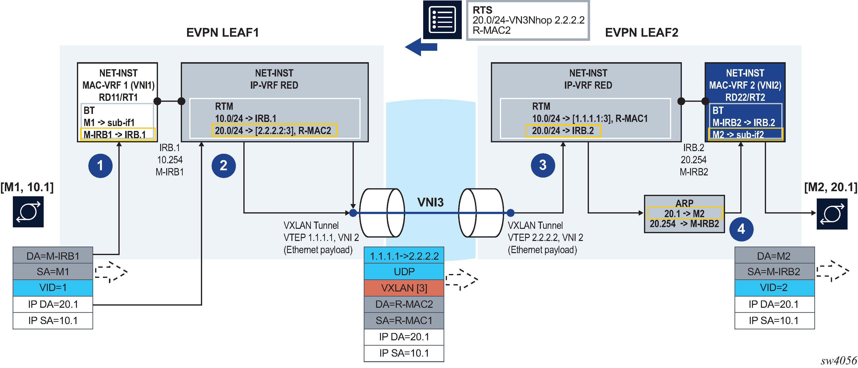
As in the asymmetric model, the frame is classified for bridge-table lookup on the MAC-VRF and processed for routing in IP-VRF red.
In contrast to the asymmetric model, a longest prefix match does not yield a local subnet, but a remote subnet reachable via [VTEP:VNI]=[2.2.2.2:3] for EVPN-VXLAN and [TEP:label] for EVPN-MPLS, and inner MAC DA R-MAC2. SR Linux supports the EVPN interface-less (EVPN IFL) model, so that information is found in the IP-VRF route-table directly; a route lookup on the IP-VRF red route-table yields a VXLAN tunnel and VNI for EVPN-VXLAN and an MPLS tunnel and service label for EVPN-MPLS.
In the case of EVPN-VXLAN, as shown in EVPN-VXLAN Layer 3 symmetric forwarding:
-
Packets are encapsulated with an inner Ethernet header and the VXLAN tunnel encapsulation.
-
The inner Ethernet header uses the system-mac as MAC SA, and the MAC advertised along with the received RT5 as MAC DA. No VLAN tag is transmitted or received in this inner Ethernet header.
At the egress PE, the packet is classified for an IP lookup on the IP-VRF red (the inner Ethernet header is ignored).
The inner and outer IP headers are updated as follows:
-
inner IP header TTL is decremented
-
outer IP header TTL is set to 255
-
outer DSCP value is marked as described in QoS for VXLAN tunnels
-
no IP MTU check is performed before or after encapsulation
Because SR Linux supports EVPN IFL, the IP lookup in the IP-VRF red route-table yields a local IRB interface.
Subsequent ARP and MAC lookups provide the information to send the routed frame to subinterface 2.
EVPN Leaf 1 in EVPN-VXLAN Layer 3 symmetric forwarding has the following configuration:
--{ [FACTORY] + candidate shared default }--[  ]--
# info
    interface ethernet-1/2 {
        admin-state enable
        vlan-tagging true
        subinterface 1 {
            type bridged
            admin-state enable
            vlan {
                encap {
                    single-tagged {
                        vlan-id 1
                    }
                }
            }
        }
    }
    interface irb0 {
        subinterface 1 {
            ipv4 {
                admin-state enable
                address 10.0.0.254/24 {
                    anycast-gw true
                }
            }
            anycast-gw {
            }
        }
    }
    network-instance ip-vrf-red {
        type ip-vrf
        interface irb0.1 {
        }
        vxlan-interface vxlan1.3 {
        }
        protocols {
            bgp-evpn {
                bgp-instance 1 {
                    admin-state enable
                    vxlan-interface vxlan1.3
                    evi 3
                }
            }
            bgp-vpn {
            }
        }
    }
    network-instance mac-vrf-1 {
        type mac-vrf
        admin-state enable
        interface ethernet-1/2.1 {
        }
        interface irb0.1 {
        }
        vxlan-interface vxlan1.1 {
        }
        protocols {
            bgp-evpn {
                bgp-instance 1 {
                    admin-state enable
                    vxlan-interface vxlan1.1
                    evi 1
                }
            }
            bgp-vpn {
            }
        }
    }
    tunnel-interface vxlan1 {
        vxlan-interface 1 {
            type bridged
            ingress {
                vni 1
            }
        }
        vxlan-interface 3 {
            type routed
            ingress {
                vni 3
            }
        }
    }
EVPN Leaf 2 in EVPN-VXLAN Layer 3 symmetric forwarding has the following configuration:
--{ [FACTORY] + candidate shared default }--[  ]--
# info
    interface ethernet-1/12 {
        admin-state enable
        vlan-tagging true
        subinterface 2 {
            type bridged
            admin-state enable
            vlan {
                encap {
                    single-tagged {
                        vlan-id 2
                    }
                }
            }
        }
    }
    interface irb0 {
        subinterface 2 {
            ipv4 {
                admin-state enable
                address 20.0.0.254/24 {
                    anycast-gw true
                }
            }
            anycast-gw {
            }
        }
    }
    network-instance ip-vrf-red {
        type ip-vrf
        interface irb0.2 {
        }
        vxlan-interface vxlan1.3 {
        }
        protocols {
            bgp-evpn {
                bgp-instance 1 {
                    admin-state enable
                    vxlan-interface vxlan1.3
                    evi 3
                }
            }
            bgp-vpn {
            }
        }
    }
    network-instance mac-vrf-2 {
        type mac-vrf
        admin-state enable
        interface ethernet-1/12.2 {
        }
        interface irb0.2 {
        }
        vxlan-interface vxlan1.2 {
        }
        protocols {
            bgp-evpn {
                bgp-instance 1 {
                    admin-state enable
                    vxlan-interface vxlan1.2
                    evi 2
                }
            }
            bgp-vpn {
            }
        }
    }
    tunnel-interface vxlan1 {
        vxlan-interface 2 {
            type bridged
            ingress {
                vni 2
            }
        }
        vxlan-interface 3 {
            type routed
            ingress {
                vni 3
            }
        }
    }
In the case of EVPN-MPLS, MPLS tunnels exist between Leaf 1 and Leaf 2, instead of VXLAN.
The following figure shows the forwarding for symmetric IRB for EVPN-MPLS services.
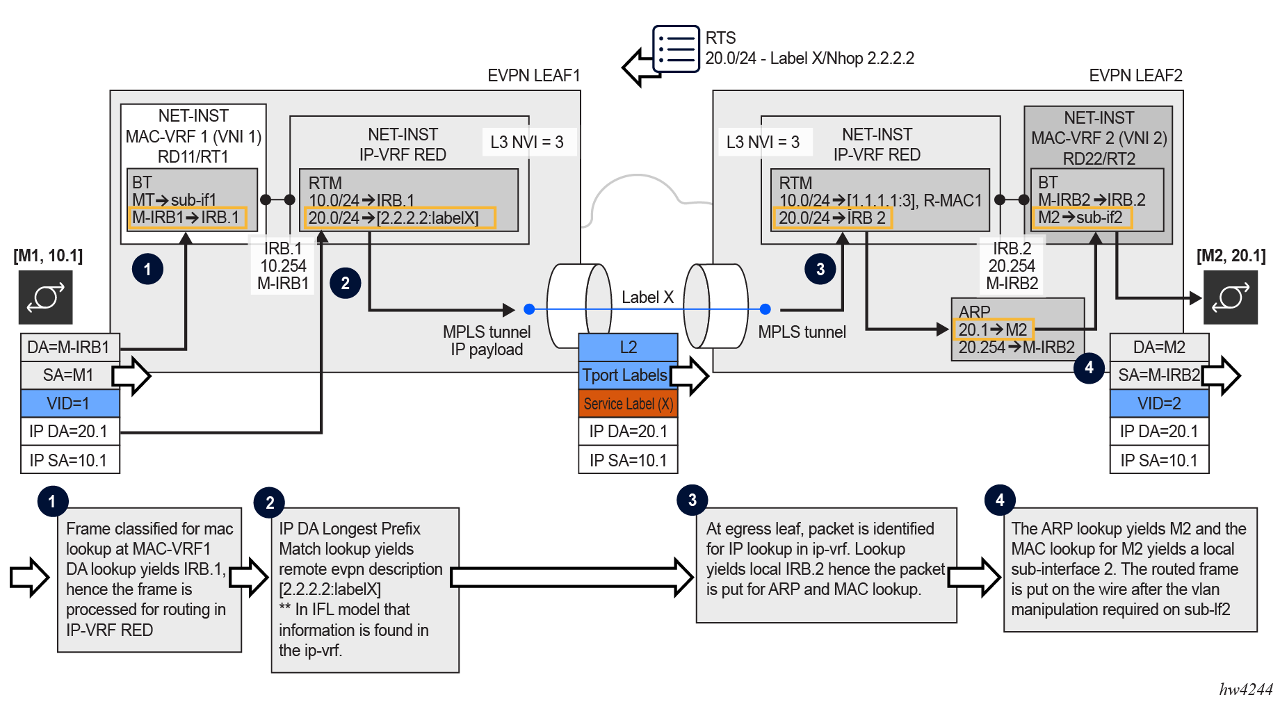
- To resolve EVPN-MPLS routes to tunnels in the tunnel table, the network instance is configured with encapsulation-type mpls and at least one MPLS tunnel type with the bgp-evpn bgp-instance mpls next-hop-resolution allowed-tunnel-types [tunnel-types] command.
- Received EVPN-MPLS next hops are resolved to the best tunnels in the allowed list.
- In order for MPLS to support the encapsulation of IP packets directly, packets are not encapsulated with an inner Ethernet header (as opposed to VXLAN which always requires inner Ethernet encapsulation).
- At the egress PE (shown as Leaf 2 in the preceding figure) and based on an ILM
lookup on Label X, the packet is classified for an IP lookup on the
ip-vrf rednetwork instance. - Subsequent ARP and MAC lookups provide the information required to send the routed packet to subinterface 2.
--{ [FACTORY] + candidate shared default }--[ ]--
A:LEAF1# info
    interface ethernet-1/2 {
        admin-state enable
        vlan-tagging true
        subinterface 1 {
            type bridged
            admin-state enable
            vlan {
                encap {
                    single-tagged {
                        vlan-id 1
                    }
                }
            }
        }
    }
    interface irb0 {
        subinterface 1 {
            ipv4 {
                address 10.0.0.254/24 {
                    anycast-gw true
                }
            }
            anycast-gw {
            }
        }
    }
    network-instance ip-vrf-red {
        type ip-vrf
        interface irb0.1 {
        }
        protocols {
            bgp-evpn {
                bgp-instance 1 {
                    admin-state enable
                    encapsulation-type mpls
                    evi 3
                    mpls {
                        next-hop-resolution {
                            allowed-tunnel-types [ldp sr-isis]
                        }
                    }
                }
            }
            bgp-vpn {
                bgp-instance 1 {
                }
            }
        }
    }
    network-instance mac-vrf-1 {
        type mac-vrf
        admin-state enable
        interface ethernet-1/2.1 {
        }
        interface irb0.1 {
        }
}-{ [FACTORY] + candidate shared default }--[ ]--
A:LEAF2# info
interface ethernet-1/12 {
admin-state enable
vlan-tagging true
subinterface 2 {
type bridged
admin-state enable
vlan {
encap {
single-tagged {
vlan-id 2
}
}
}
}
}
interface irb0 {
subinterface 2 {
ipv4 {
address 20.0.0.254/24 {
anycast-gw true
}
}
anycast-gw {
}
}
}
network-instance ip-vrf-red {
type ip-vrf
interface irb0.2 {
}
protocols {
bgp-evpn {
bgp-instance 1 {
admin-state enable
encapsulation-type mpls
evi 3
mpls {
next-hop-resolution {
allowed-tunnel-types [ldp sr-isis]
}
}
}
}
bgp-vpn {
bgp-instance 1 {
}
}
}
}
network-instance mac-vrf-2 {
type mac-vrf
admin-state enable
interface ethernet-1/12.2 {
}
interface irb0.2 {
}
}Anycast gateways
Anycast gateways (anycast-GWs) are a common way to configure IRB subinterfaces in DC leaf nodes. Configuring anycast-GW IRB subinterfaces on all leaf nodes of the same BD avoids tromboning for upstream traffic from hosts moving between leaf nodes.
The following figure shows an example anycast-GW IRB configuration.
Anycast-GWs allow configuration of the same IP and MAC addresses on the IRB interfaces of all leaf switches attached to the same BD; for example, SRL LEAF-1 and SRL LEAF-2 in the preceding figure. This feature optimizes the south-north forwarding because a host’s default gateway always belongs to the connected leaf, irrespective of the host moving between leaf switches; for example VM3 moving from SRL LEAF-1 to SRL LEAF-2 in the figure.
When an IRB subinterface is configured as an anycast-GW, it must have one IP address configured as anycast-gw. The subinterface may or may not have other non-anycast-GW IP addresses configured.
To simplify provisioning, an option to automatically derive the anycast-GW MAC is supported, as described in RFC 9135. The auto-derivation uses a virtual-router-id similar to MAC auto-derivation in RFC 5798 (VRRP). Anycast-GWs use a default virtual-router-id of 01, if not explicitly configured. Because only one anycast-gw-mac per IRB sub-interface is supported, the anycast-gw-mac for IPv4 and IPv6 is the same in the IRB sub-interface.
The following is an example configuration for an anycast-GW subinterface:
// Configuration Example of an anycast-gw IRB sub-interface

[interface irb1 subinterface 1 ]
A:leaf-1/2# info
  ipv4 {
    admin-state enable
    address 10.0.0.254/24 {
      primary true
      anycast-gw true
    }
  }
  anycast-gw {
    virtual-router-id 2
  }

// State Example of an anycast-gw IRB sub-interface

[interface irb1 subinterface 1 ]
A:leaf-1/2# info from state
  ipv4 {
    address 10.0.0.254/24 {
      primary true
      anycast-gw true
    }
  }
  anycast-gw {
    virtual-router-id 2
    anycast-gw-mac 00:00:5e:00:01:02
    anycast-gw-mac-origin auto-derived
  }
The anycast-gw true command designates the associated IP address as an anycast-GW address of the subinterface and associates the IP address with the anycast-gw-mac address in the same sub-interface. ARP requests or NSs received for the anycast-GW IP address are replied using the anycast-gw-mac address, as opposed to the regular system-derived MAC address. Similarly, CPM-originated GARPs or unsolicited NAs sent for the anycast-GW IP address use the anycast-gw-mac address as well. Packets routed to the IRB use the anycast-gw-mac as the SA in Ethernet header.
All IP addresses of the IRB subinterface and their associated MACs are advertised in MAC/IP routes with the static flag set. The non-anycast-GW IPs are advertised along with the interface hardware MAC address, and the anycast-GW IP addresses along with the anycast-gw-mac address.
In addition, the anycast-gw true command makes the system skip the ARP/ND duplicate-address-detection procedures for the anycast-GW IP address.
EVPN Layer 3 multihoming and anycast gateways
In an EVPN Layer 3 scenario, all IRB interfaces facing the hosts must have the same IP address and MAC; that is, an anycast-GW configuration. This avoids inefficiencies for all-active multihoming or speeds up convergence for host mobility.
The use of anycast-GW along with all-active multihoming in an EVPN-VXLAN scenario is shown in the following figure:
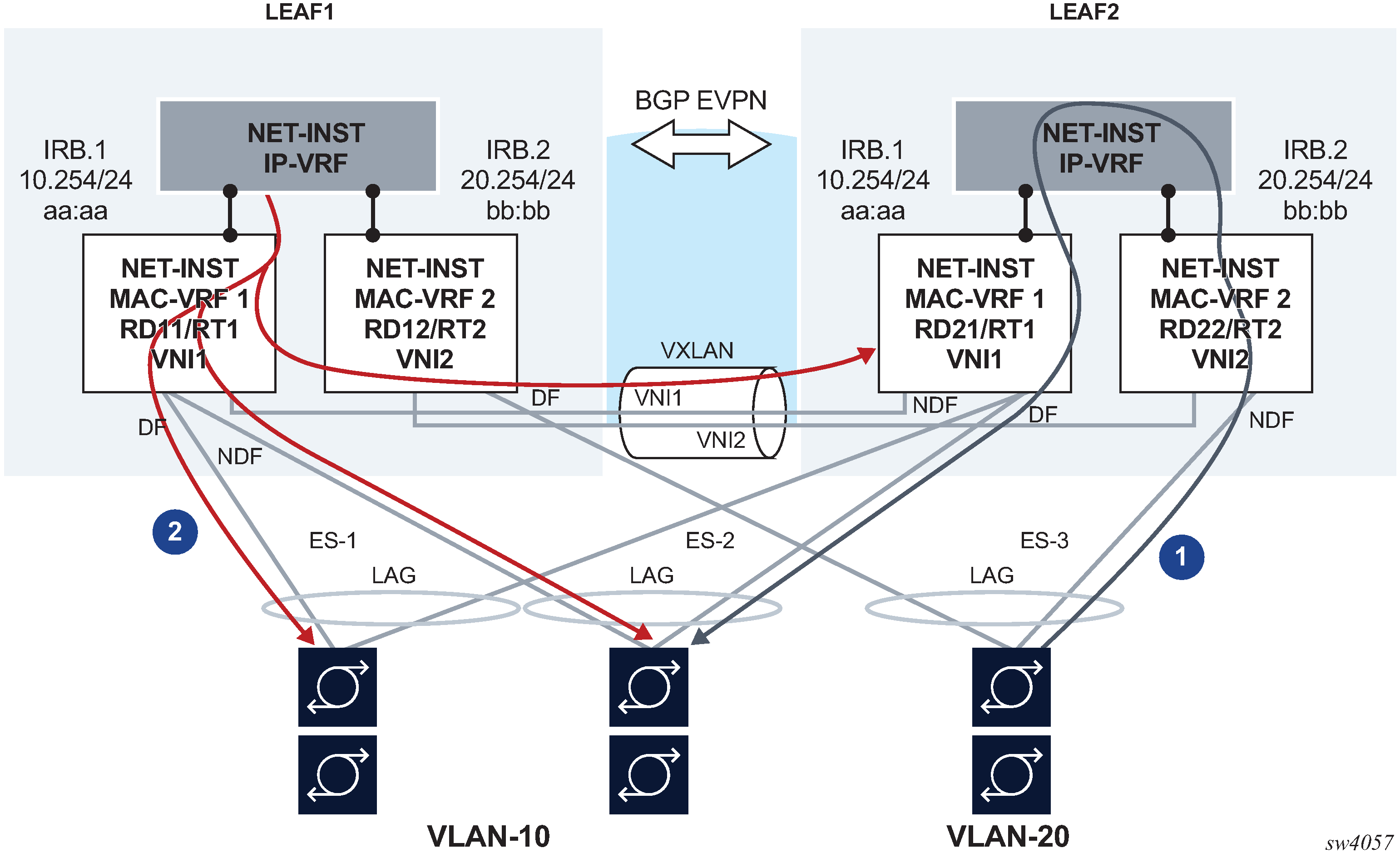
In this example:
-
Routed unicast traffic is always routed to the directly connected leaf (no tromboning).
-
BUM traffic sent from the IRB interface is sent to all DF and NDF subinterfaces, similar to BUM entering a subinterface.
This applies to:
-
system-generated unknown unicast or broadcast traffic
-
ARP requests, GARPs, and Neighbor Discovery multicast messages
-
unicast traffic with unknown MAC DA
-
This solution also applies when EVPN-MPLS is used on MAC-VRFs instead of VXLAN. Flooded traffic coming from the IRB interface to the MAC-VRF is flooded to local DF subinterfaces and to other leaf nodes attached to the same broadcast domain.
When a host connected to ES-3 sends a unicast flow to be routed in the IP-VRF, the flow must be routed in the leaf receiving the traffic, irrespective of the server hashing the flow to Leaf-1 or Leaf-2. To do this, the host is configured with only one default gateway, 20.254/24. When the host ARPs for it, it does not matter if the ARP request is sent to Leaf-1 or Leaf-2. Either leaf replies with the same anycast-GW MAC, and when receiving the traffic either leaf can route the packet.
This scenario is supported on IP-VRF network instances and the default network instance.
When IRB subinterfaces are attached to MAC-VRF network instances with all-active
multihoming ESs, set the arp timeout / neighbor-discovery
stale-time settings on the IRB subinterface to a value that is 30 seconds lower
than the age-time configured in the MAC-VRF. This setting avoids transient
packet loss situations triggered by the MAC address of an active ARP/ND entry being removed
from the MAC table.
EVPN Layer 3 host route mobility
EVPN host route mobility refers to the procedures that allow the following:
learning ARP/ND entries out of unsolicited messages from hosts
generating host routes out of those ARP/ND entries
refreshing the entries when mobility events occur within the same BD
EVPN host route mobility is part of basic EVPN Layer 3 functionality as defined in RFC 9135.
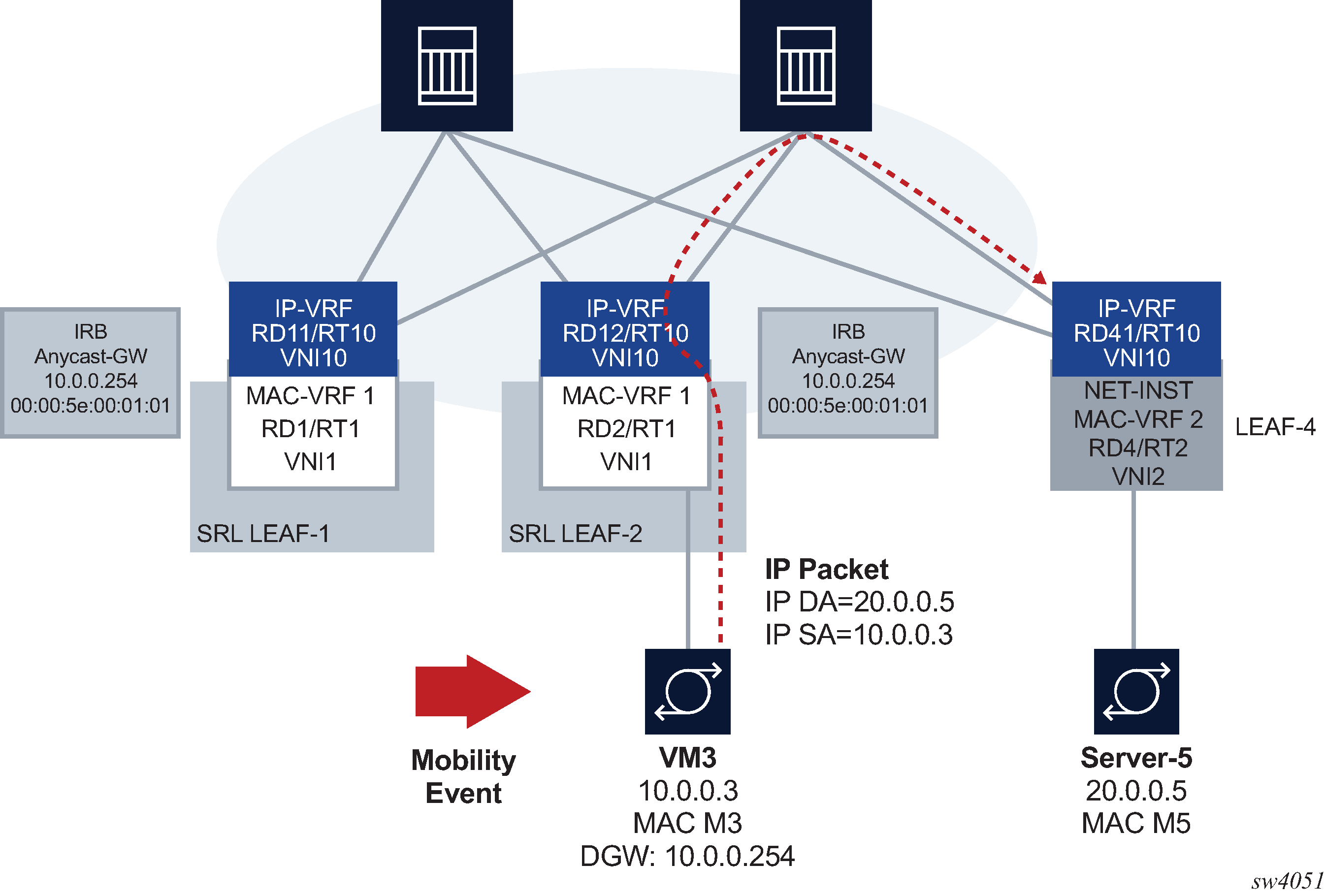
The following figure EVPN host route mobility.
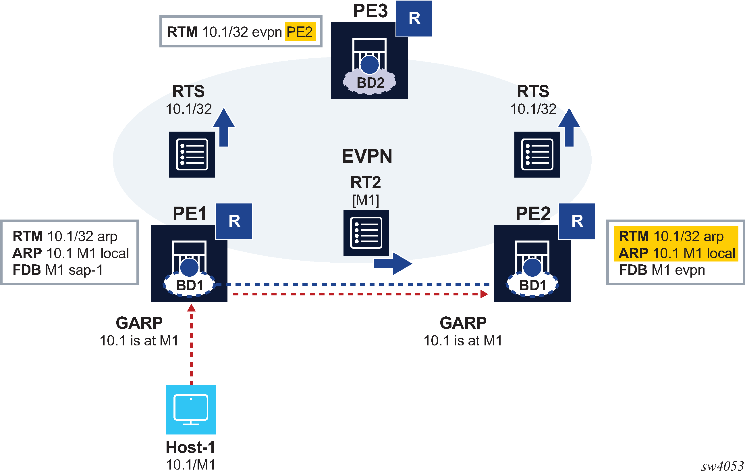
In EVPN host route mobility a host is attached to PE1, so all traffic from PE3 to that host must be forwarded directly to PE1. When the host moves to PE2, all the tables must be immediately updated so that PE3 sends the traffic to PE2. EVPN host route mobility works by doing the following:
snooping and learning ARP/ND entries for hosts upon receiving unsolicited GARP or NA messages
creating host routes out of those dynamic ARP/ND entries. These routes only exist in the control plane and are not installed in the forwarding plane to avoid FIB exhaustion with too many /32 or /128 host routes.
advertising the locally learned ARP/ND entries in MAC/IP routes so that ARP/ND caches can be synchronized across leaf nodes
advertising the host routes as IP prefix routes
triggering ARP/ND refresh messages for changes in the ARP/ND table or MAC table for a specific IP, which allows updating the tables without depending on the ARP/ND aging timers (which can be hours long)
The following configuration enables an anycast-GW IRB subinterface to support mobility procedures:
// Example of the configuration of host route mobility features

--{ candidate shared default }--[ interface irb1 subinterface 1 ]--
A:-# info
    ipv4 {
        admin-state enable
        address 10.0.0.254/24 {
            anycast-gw true
            primary
        }
        arp {
            learn-unsolicited true
            host-route {
                populate static
                populate dynamic
            }
            evpn {
                advertise static
                advertise dynamic
            }
        }
    }
    ipv6 {
        admin-state enable
        address 200::254/64 {
            anycast-gw true
            primary
        }
        neighbor-discovery {
            learn-unsolicited true
            host-route {
                populate static
                populate dynamic
            }
            evpn {
                advertise static
                advertise dynamic
            }
        }
    }
    anycast-gw {
    }
--{ candidate shared default }--[ interface irb1 subinterface 1 ]--
# info from state
    admin-state enable
    ip-mtu 1500
    name irb1.1
    ifindex 1082146818
    oper-state up
    last-change "a minute ago"
    ipv4 {
        allow-directed-broadcast false
        address 10.0.0.254/24 {
            anycast-gw true
            origin static
        }
        arp {
            duplicate-address-detection true
            timeout 14400
            learn-unsolicited true
            host-route {
                populate static
                populate dynamic
                }
            }
        }
    }
    ipv6 {
        address 200::254/64 {
            anycast-gw true
            origin static
            status unknown
        }
        address fe80::201:1ff:feff:42/64 {
            origin link-layer
            status unknown
        }
        neighbor-discovery {
            duplicate-address-detection true
            reachable-time 30
            stale-time 14400
            learn-unsolicited both
            host-route {
                populate static
                populate dynamic
            }
        }
        router-advertisement {
            router-role {
                current-hop-limit 64
                managed-configuration-flag false
                other-configuration-flag false
                max-advertisement-interval 600
                min-advertisement-interval 200
                reachable-time 0
                retransmit-time 0
                router-lifetime 1800
            }
        }
    }
    anycast-gw {
        virtual-router-id 1
        anycast-gw-mac 00:00:5E:00:01:01
        anycast-gw-mac-origin vrid-auto-derived
    }
...
In this configuration, when learn-unsolicited is set to true,
the node processes all solicited and unsolicited ARP/ND flooded messages received on
subinterfaces (no
VXLAN/MPLS)
and learns the corresponding ARP/ND entries as dynamic. By default, this setting is
false, so only solicited entries are learned by default.
The advertisement of EVPN MAC/IP routes for the learned ARP entries must be enabled/disabled by configuration; it is disabled by default. In the example above, this is configured with the advertise dynamic and advertise static settings.
The creation of host routes in the IP-VRF route table out of the dynamic or static ARP entries
can be enabled/disabled by configuration; it is disabled by default. In the example
above, this is configured with the host-route populate dynamic and
host-route populate static settings.
By default, the ARP/ND host routes are not installed in the data path. You can configure
host-route populate dynamic datapath-programming true to change
this default behavior so that the ARP/ND host routes are installed in the data path.
This configuration is required when the ARP/ND host routes are leaked. See "Network
instance route leaking" in the SR Linux Configuration Basics Guide.
The dynamic ARP entries are refreshed without any extra configuration. The system sends ARP requests for the dynamic entries to make sure the hosts are still alive and connected.
EVPN-VXLAN IFL interoperability with EVPN IFF
By default, the SR Linux EVPN IFL (interface-less) model, described in Symmetric IRB interface-less ip-vrf-to-ip-vrf model for VXLAN, does not interoperate with the EVPN IFF (interface-ful) model, as supported on, for example, Nuage WBX devices. However, it is possible to configure the SR Linux EVPN IFL model to interoperate with the EVPN IFF model.
To do this, configure the advertise-gateway-mac command for the IP-VRF network instance. When this command is configured, the node advertises a MAC/IP route using the following:
gateway-mac for the IP-VRF (that is, the system-mac)
RD/RT, next-hop, and VNI of the IP-VRF where the command is configured
null IP address, ESI or Ethernet Tag ID
Nuage WBX devices support two EVPN Layer 3 IPv6 modes: IFF unnumbered and IFF numbered, as described in RFC 9136. The SR Linux interoperability mode enabled by the advertise-gateway-mac command only works with Nuage WBX devices that use the EVPN IFF unnumbered model. This is because the EVPN IFL and EVPN IFF unnumbered models both use the same format in the IP prefix route, and they differ only in the additional MAC/IP route for the gateway-mac. The EVPN IFL and EVPN IFF numbered models have different IP prefix route formats, so they cannot interoperate.
The following example enables interoperability with the Nuage EVPN IFF unnumbered model:
--{ [FACTORY] + candidate shared default }--[  ]--
# info from state network-instance protocols bgp-vpn
  bgp-evpn {
      bgp-instance 1 {
          admin-state enable
          vxlan-interface vxlan1.2
          routes {
              route-table {
                  mac-ip {
                      advertise-gateway-mac true
                  }
              }
          }
      }
  }
VIP discovery for redundant servers
In data centers, it is common to have clusters of servers sharing the same IP address and working in an active-standby mode, so that only one of the servers in the cluster is active at a time. This shared IP address is known as a virtual IP (VIP) address. SR Linux can discover which server in the cluster owns the VIP address.
ARP requests (NS for IPv6) from a leaf node or gratuitous ARP (unsolicited NA for IPv6) from a server are used to discover which host owns the VIP. Among the servers sharing the VIP, only the active one either sends a gratuitous ARP (or unsolicited NA) or replies to the ARP request (NS) from the leaf node. If a server does not send a gratuitous ARP, you can optionally configure SR Linux to send ARP requests periodically at a specified probe interval.
The leaf nodes create entries in their ARP tables that map the VIP to the MAC address of the active server. You can optionally configure a list of allowed MAC addresses so that the ARP/ND entry for the VIP is created only if the reply from the server comes from one of the MACs on the allowed list.
The following figure shows a configuration where three SR Linux devices in a MAC-VRF are connected to a redundant server group.
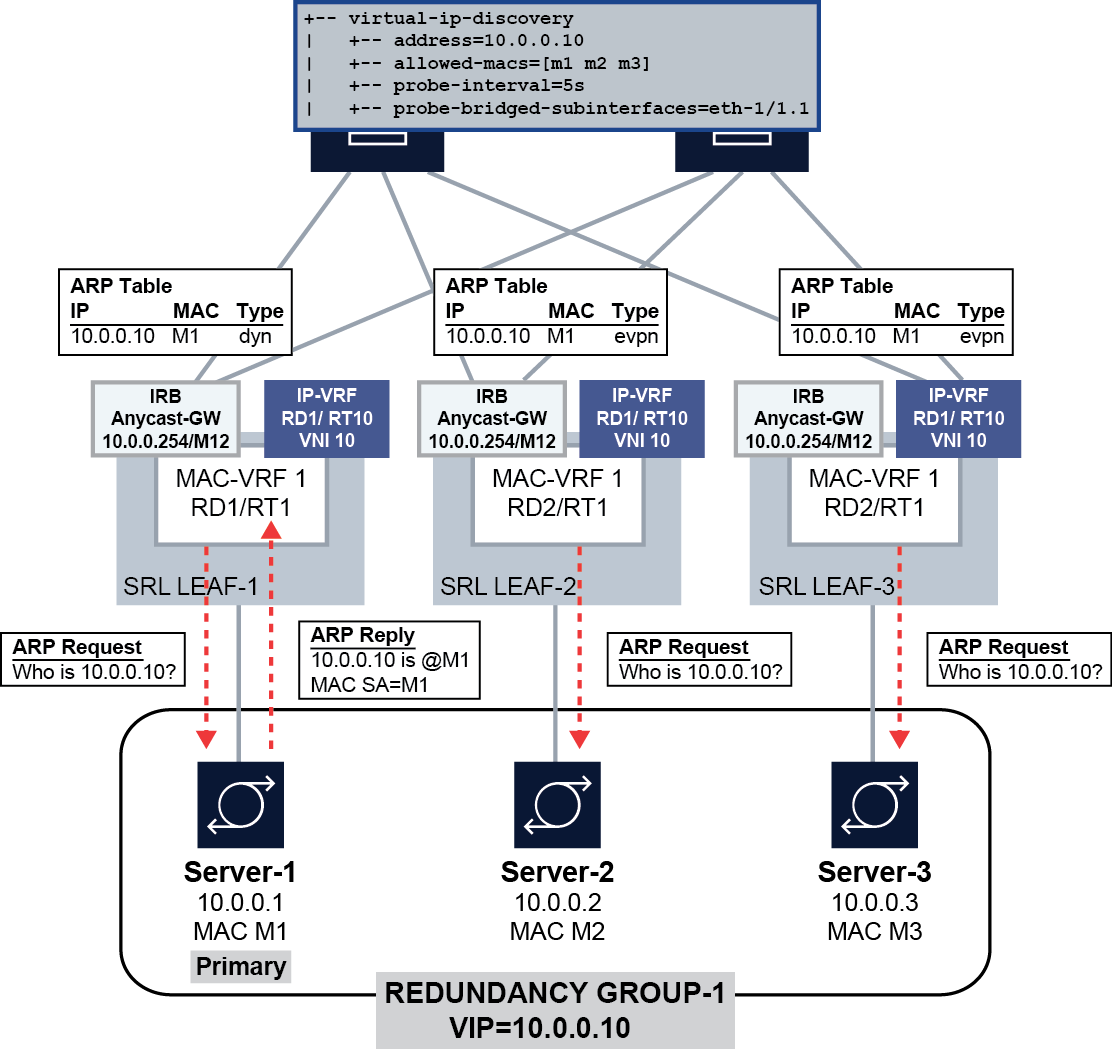
In this configuration, the SR Linux devices (SRL LEAF-1/2/3) start sending ARP requests for the VIP 10.10.10.10 on the ethernet 1/1.1 subinterface every 5 seconds until the ARP entry for the VIP/VMAC is learned. The ARP entry is created only if the MAC address matches one of the allowed MACs: M1, M2, or M3.
Initially, Server-1 is the primary server in the server group, and it responds to the ARP request from Leaf-1, causing the server's MAC address M1 to be added to the ARP table on the SR Linux devices for VIP 10.10.10.10. If Server-2 (MAC M2) becomes the primary server, it sends out a gratuitous ARP message or responds to an ARP request from LEAF-2, which triggers an update of the ARP table on Leaf-2 and a MAC/IP route update with 10.10.10.10/M2. When Leaf-1 receives the update, it updates its ARP table immediately with the new entry.
VIP discovery is supported on single-homed and multihomed subinterfaces. For all-active multihoming, and based on the local-bias behavior, the ARP/ND probes are sent to all ES subinterfaces irrespective of their DF state. When the active server replies, the MAC/IP route is synchronized in the other ES peers based on the functionality described in EVPN Layer 3 host route mobility.
Configuring VIP discovery
To configure VIP discovery for an IRB interface, you specify the bridged subinterfaces that can be sent probe messages (ARP requests) for the VIP, optionally a probe interval that determines how often the probe messages are sent, and optionally a list of allowed MAC addresses that indicate the MAC addresses of the servers in the group.
Configure VIP discovery for IPv4
--{ candidate shared default }--[  ]--
# info interface irb1 subinterface 1 ipv4 arp
 interface irb1 {
        subinterface 1 {
            ipv4 {
                admin-state enable
                arp {
                    virtual-ipv4-discovery {
                        address 10.10.10.10 {
                            probe-bridged-subinterfaces [
                                ethernet-1/1.1
                            ]
                            probe-interval 5
                            allowed-macs [
                                00:14:9C:78:E2:E1
                                00:14:9C:78:E2:E2
                                00:14:9C:78:E2:E3
                            ]
                        }
                    }
                }
            }
        }
    }
Configure VIP discovery for IPv6
--{ candidate shared default }--[  ]--
# info interface irb1 subinterface 1 ipv6 neighbor-discovery
    interface irb1 {
        subinterface 1 {
            ipv6 {
                admin-state enable
                neighbor-discovery {
                    virtual-ipv6-discovery {
                        address 2001::10:10:10:10 {
                            probe-interval 5
                            allowed-macs [
                                00:14:9C:78:E2:E1
                                00:14:9C:78:E2:E2
                                00:14:9C:78:E2:E3
                            ]
                            probe-bridged-subinterfaces [
                                ethernet-1/1.1
                            ]
                        }
                    }
                }
            }
        }
    }
In this configuration, SR Linux starts sending ARP requests for VIP 10.10.10.10
(address parameter) on the ethernet 1/1.1
subinterface (probe-bridged-subinterfaces parameter) every 5
seconds (probe-interval parameter) so that the ARP entry for
the VIP/VMAC is learned. The ARP entry is created only if the MAC address matches
one of the MACs in the allowed list (allowed-macs
parameter).
Up to 10 subinterfaces can be specified in the probe-bridged-subinterfaces list. The probe messages are sent only to the subinterfaces in this list. If no subinterfaces are specified in the list, no probe messages are sent.
- the VIP is configured
- when the IRB interface becomes operationally up (when the prefix becomes preferred)
- when the ARP/ND entry corresponding to the VIP moves from type dynamic to type EVPN, or from type dynamic to type dynamic (changing to a different MAC)
- when subinterfaces in the probe-bridged-subinterfaces list become operationally up
- when the arpnd_mgr application restarts
- when the allowed-macs list, probe-interval, or probe-bridged-subinterfaces list changes
When the probe-interval is set to a non-zero value, SR Linux keeps probing for the VIP continuously, even after the ARP/ND entry for the VIP is created.
Up to 10 MAC addresses can be specified in the allowed-macs list. The ARP/ND entry for the VIP is created only if the resolving MAC address corresponds to one of the MAC addresses in the list. If no MAC addresses are specified in the list, any resolving MAC is valid for the creation of the ARP/ND entry. When a MAC address included in the allowed-macs list is used in an existing ARP/ND entry, and the MAC is removed from the list, the ARP/ND entry is deleted.
Displaying VIP discovery information
You can display the number of probe packets sent by the SR Linux device using the info from state command. Statistics are displayed for probe packets on individual VIPs and the total number of probe packets for all VIPs configured for the subinterface.
--{ candidate shared default }--[  ]--
# info from state interface irb1 subinterface 1 ipv4 arp
    interface irb1 {
        subinterface 1 {
            ipv4 {
                arp {
                    virtual-ipv4-discovery {
                        address 10.10.10.10 {
                            probe-bridged-subinterfaces [
                                ethernet-1/1.1
                            ]
                            probe-interval 5
                            allowed-macs [
                                00:14:9C:78:E2:E1
                                00:14:9C:78:E2:E2
                                00:14:9C:78:E2:E3
                            ]
                            statistics {
                                out-probe-packets 100
                            }
                        statistics {
                            out-total-probe-packets 100
                        }
                    }
                }
            }
        }
    }
Layer 3 proxy-ARP/ND
- Deployments that use a Layer 3 multihoming solution, but are unable to run EVPN, ESs or VXLAN/MPLS.
- Virtual subnet scenarios, where leaf nodes are attached to different broadcast domains (BDs), but the hosts connected to them are part of the same subnet. RFC 7814 describes this type of solution.
The following figure shows an example virtual subnet configuration that uses this feature.
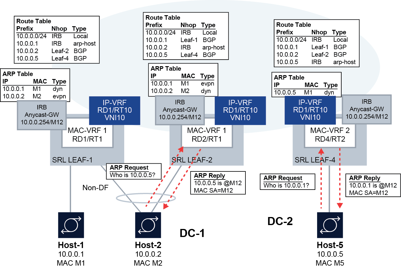
In this example, SR Linux Leaf-1/Leaf-2 and SR Linux-4 are attached to different BDs; however, the hosts connected to them are part of the same subnet. This type of configuration is typically used in scenarios where the BDs are kept deliberately small, while hosts of the same subnet can be part of more than one of the BDs. This is the case described in RFC 7814.
Layer 3 proxy-ARP/ND triggers the router to reply to any ARP-request or NS from hosts, so that the traffic is attracted to the IRB subinterface and forwarded by the router to a destination on the same subinterface from which the request came or a different subinterface or route.
Layer 3 proxy-ARP/ND is intended to be used along with the learn-unsolicited and
host-route populate features, so that ARP/ND entries are generated
and host routes created out of them and advertised by the routing protocol enabled in
the routing network instance (default or IP-VRF).
This feature is supported on IRB and other Layer 3 subinterfaces. EVPN may or may not be enabled on the attached MAC-VRF. The subinterfaces can be attached to an IP-VRF or the default network instance.
Layer 3 proxy-ARP
When Layer 3 proxy-ARP is enabled, all ARP-requests are copied to the CPM and replied using the
anycast-gw MAC, if configured; otherwise, the interface
hw-mac-address MAC is used. This process is irrespective of the
target IP address of the ARP-request being in the ARP table or in the route-table.
The system does not reply to gratuitous ARP (GARP) requests, where the ARP Sender Protocol Address and ARP Target Protocol Address are both set to the IP address of the cache entry to be updated.
When Layer 3 proxy-ARP is enabled, the router replies to any ARP-request unconditionally if received over a bridged subinterface. If the ARP-request is received over VXLAN/MPLS, the router replies only if the ARP-request is targeted to its own IP; if it is targeted to a non-local IP on the IRB, the ARP-request is flooded to local bridged subinterfaces, changing the source MAC and IP with the local ones.
If the original ARP-request came on a bridged subinterface, and the target IP has not been learned on the subinterface yet, the router sends an ARP-request with its own source information to get the target IP learned as soon as possible.
- If the received packets have an IP DA with an ARP entry on the same subinterface over which the ARP-request was received, the router forwards the packets to the next-hop indicated by the ARP entry.
- If the received packets have an IP DA with an ARP entry on a different subinterface, the router forwards the packets to the next-hop indicated by the ARP entry.
- If the received packets have an IP DA with a matching route in the route-table, the router forwards the packets based on the route-table entry.
- Otherwise, the attracted traffic is dropped.
The Layer 3 proxy-ARP feature does not require a route lookup before replying to the received ARP-requests. The received ARP-requests are only copied to CPM; they are not flooded to other objects in the MAC-VRF.
The ICMP redirects generated by XDP CPM are suppressed for IP packets targeting an IP address within the same subnet.
Received ARP-replies with a DA not equal to the local MAC, if any are received, are forwarded based on a mac-table lookup.
learn-unsolicited is
required to create an ARP entry.Configuring Layer 3 proxy-ARP
To configure Layer 3 proxy-ARP, enable it on a subinterface.
--{ candidate shared default }--[  ]--
# info interface ethernet-1/1 subinterface 1 ipv4 arp proxy-arp
    interface ethernet-1/1 {
        subinterface 1 {
            ipv4 {
                admin-state enable
                arp {
                    proxy-arp true
                }
            }
        }
    }
Layer 3 proxy-ND
When Layer 3 proxy-ND is enabled, it functions similarly to Layer 3 proxy-ARP. All NS
messages sent to the Solicited-Node multicast address
[ff02::1:ff][low-3-bytes-unicast-ip] are copied to CPM, and all of
the NS messages are replied using the anycast-gw MAC, if configured (or
interface hw-mac-address otherwise), without any route lookup.
Received NS messages are only copied to CPM and not flooded in the BD. In this way, the feature provides an implicit ND flood suppression.
The learn-unsolicited command is not needed to learn a neighbor from an NS, because it is basic ND behavior to create a neighbor for the SA of an NS if there is a reply and it is a valid neighbor.
Configuring Layer 3 proxy-ND
To configure Layer 3 proxy-ND, enable it on a subinterface.
--{ candidate shared default }--[  ]--
# info interface ethernet-1/1 subinterface 1 ipv6 neighbor-discovery
    interface ethernet-1/1 {
        subinterface 1 {
            ipv6 {
                neighbor-discovery {
                    proxy-nd true
                }
            }
        }
    }
EVPN IP aliasing
As defined in draft-ietf-bess-evpn-ip-aliasing, IP aliasing can be used with EVPN Layer 3 Ethernet Segments (ESs) to load-balance traffic to a host connected to multiple leaf nodes attached to the same IP-VRF, even if some of the leaves do not advertise reachability to that host.
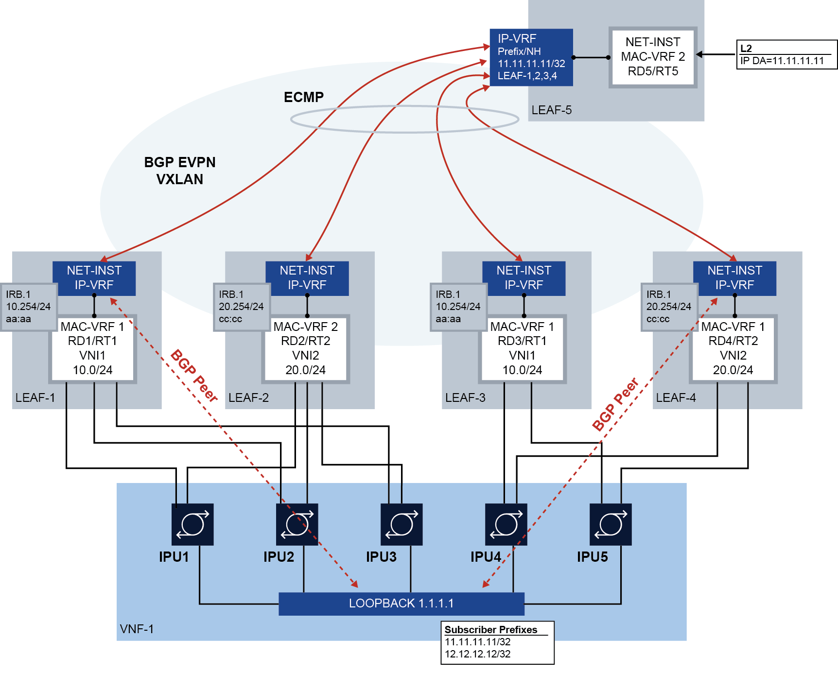
SR Linux supports using IP aliasing for BGP peering where leaf switches are multihomed to a single virtual/container network function (referred to as VNF in this section) loopback address. The following figure shows this type of configuration.
EVPN-VXLAN is used to describe IP aliasing in this section, however IP aliasing is also applicable to EVPN-MPLS services.
In this configuration, leaf nodes LEAF-1 through LEAF-5 are connected to an EVPN Layer 3 tenant domain, and four of these leaf nodes are multihomed to the same VNF. This VNF has five IPUs, similar to line cards, that are each dual-homed to two leaf nodes. Each IPU has two Layer 3 links that are connected to the leaf switches.
MAC-VRF 1 and MAC-VRF 2 are different Broadcast Domains (BDs) and have no Layer 2 EVPN connectivity between them.
The VNF is attached to a pair of subscriber prefixes, 11.11.11.11/32 and 12.12.12.12/32, that must be advertised to the leaf nodes, peering from the IP-VRF IRB interfaces, so the leaf nodes can distribute the reachability to the rest of the network.
In this example, the VNF can run PE-CE BGP from loopback interface 1.1.1.1/32, but supports a maximum of two BGP sessions.
In this configuration, IP aliasing on SR Linux allows the following:
-
Full traffic spraying in both upstream and downstream directions, even though the number of BGP sessions is limited to two, and the VNF connects to four leaf nodes.
-
No tromboning for downstream traffic routed to a leaf node that does not have a BGP session with the VNF. The local leaf must always route locally to the VNF, unless the VNF loopback becomes unreachable.
For example, when LEAF-5 sends traffic with destination 11.11.11.11 to LEAF-3, LEAF-3 needs to route locally to its local MAC-VRF 1, even if it has an RT5 in its route table pointing at LEAF-1 or LEAF-4.
EVPN IP aliasing on SR Linux
The following figure shows how IP aliasing on SR Linux works for BGP peering to a VNF loopback. To simplify the explanation, only two leaf nodes are shown; however, multiple leaf nodes can be multihomed to the same VNF loopback.
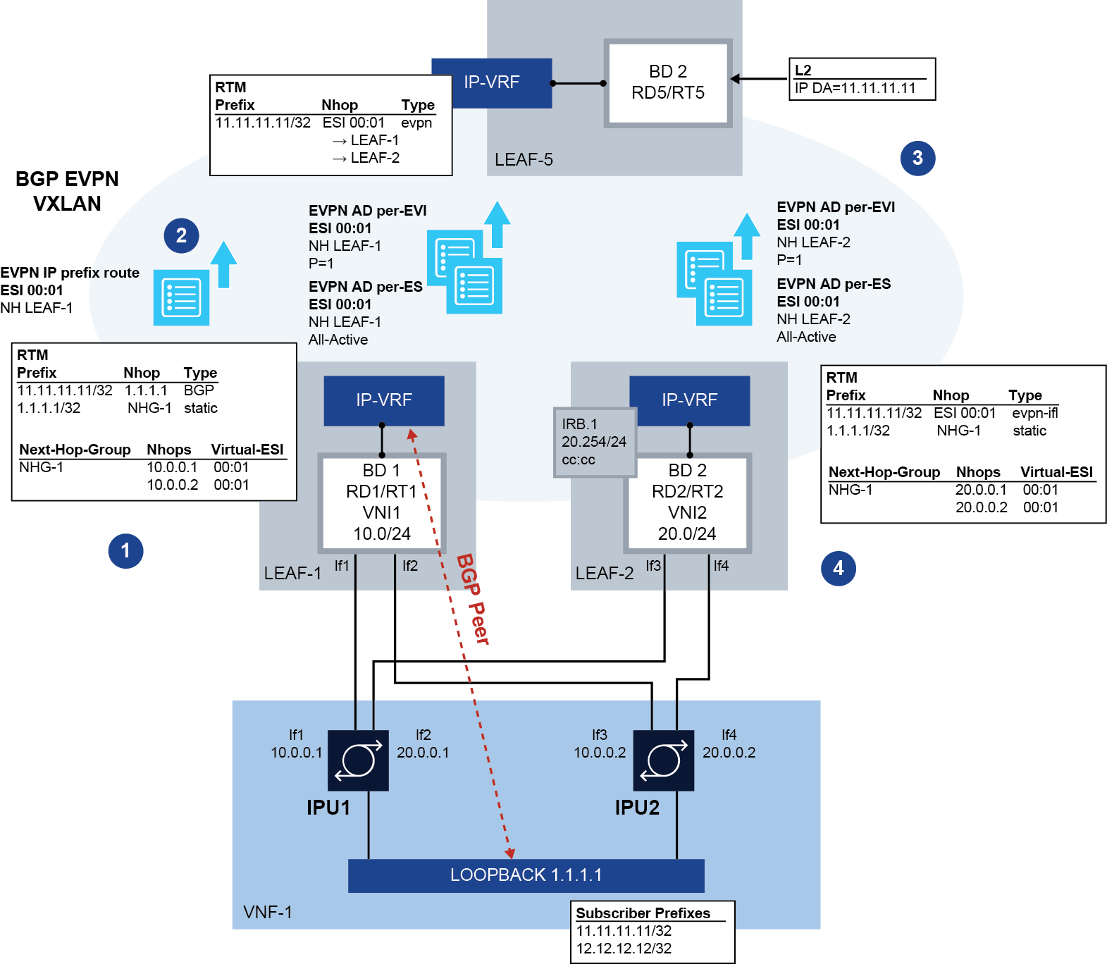
- The VNF's loopback address (1.1.1.1) is associated with virtual Layer 3 ES
ES-1 on both LEAF-1 and LEAF-2, working in all-active mode. Static routes to
1.1.1.1/32 are configured on both leaf switches. These static routes can run
BFD to the VNF, if required, to speed up fault detection.
After ES-1 is enabled, and as soon as 1.1.1.1 has a route (of any mask length) in the IP-VRF's route table, LEAF-1 and LEAF-2 advertise an EVPN ES route, as well as EVPN Auto Discovery (AD) per ES and per EVI routes for ES-1. The AD routes are advertised based on the presence of a route for 1.1.1.1 in the route table. In this example, the route for 1.1.1.1/32 is statically configured in the route table, but any non-EVPN IP prefix route that provides reachability to 1.1.1.1 would trigger the advertisement of the AD routes.
If the ES ES-1 oper-state is up and a route for 1.1.1.1 is active in the route table, each leaf advertises:
- AD per-ES route for ES-1, indicating all-active mode
- AD per-EVI route for ES-1, indicating P = 1 (primary state is set), with route distinguisher and route target of the IP-VRF
The AD per-EVI routes contain two flags, P (primary) and B (backup), which provide an indication for the remote nodes to know whether they can send traffic to the owners of the routes. The remote nodes send traffic for the ES to all the nodes advertising themselves as primary (P = 1), and not to nodes signaling P = 0, B = 1, unless there are no primary nodes left in the ES.
For all-active multihoming mode, there is no DF election in the context of the ES.
- Any prefixes that are resolved to the next-hop associated with ESI-1 are advertised as EVPN IP prefix routes with ESI 00:01 (representation of the ESI for ES-1). In the example in EVPN IP aliasing on SR Linux, prefix 11.11.11.11/32 is advertised as an EVPN IP prefix route with ESI 00:01.
- LEAF-5 identifies the EVPN IP prefix route with ESI 00:01 and installs the
route in the IP-VRF route table with as many next-hops as received AD routes
with ESI 00:01 and the primary flag set (P = 1). That is, the IP prefix
route with ESI 00:01 is recursively resolved to the next hops that advertise
the AD per-EVI (with P = 1) and per-ES routes for 00:01.
If the virtual Layer 3 ES is configured as single-active, a DF Election among all the leaf nodes attached to the same ES determines which leaf nodes advertise themselves as primary for the ES.
- LEAF-2 identifies the EVPN IP prefix route with ESI 00:01 and next-hop
LEAF-1 and resolves the route recursively to the next-hop associated with
ES-1.
If the static route associated with ES-1 goes down, the leaf withdraws the associated Layer 3 AD per-EVI/ES routes to avoid attracting traffic from LEAF-5.
Centralized routing model and PE-CE routes resolved over EVPN-IFL
SR Linux supports PE-CE sessions over VXLAN/MPLS and PE-CE next-hop resolution via EVPN-IFL, which, along with Layer 3 ES, enables support for the centralized routing model, shown in Centralized routing model.
This model uses BGP PE-CE peering on CEs to a pair of centralized anchor leaf nodes, as opposed to BGP PE-CE sessions to the directly connected leaf nodes. This is possible because BGP PE-CE route resolution via EVPN IFL routes is unblocked, which is necessary when the BGP session is not established via a local subinterface.
Having all the BGP PE-CE sessions centralized in a pair of anchor leaf nodes simplifies the provisioning of BGP not only on the rest of the leaf nodes, but also on the CEs connected to the leaf nodes.
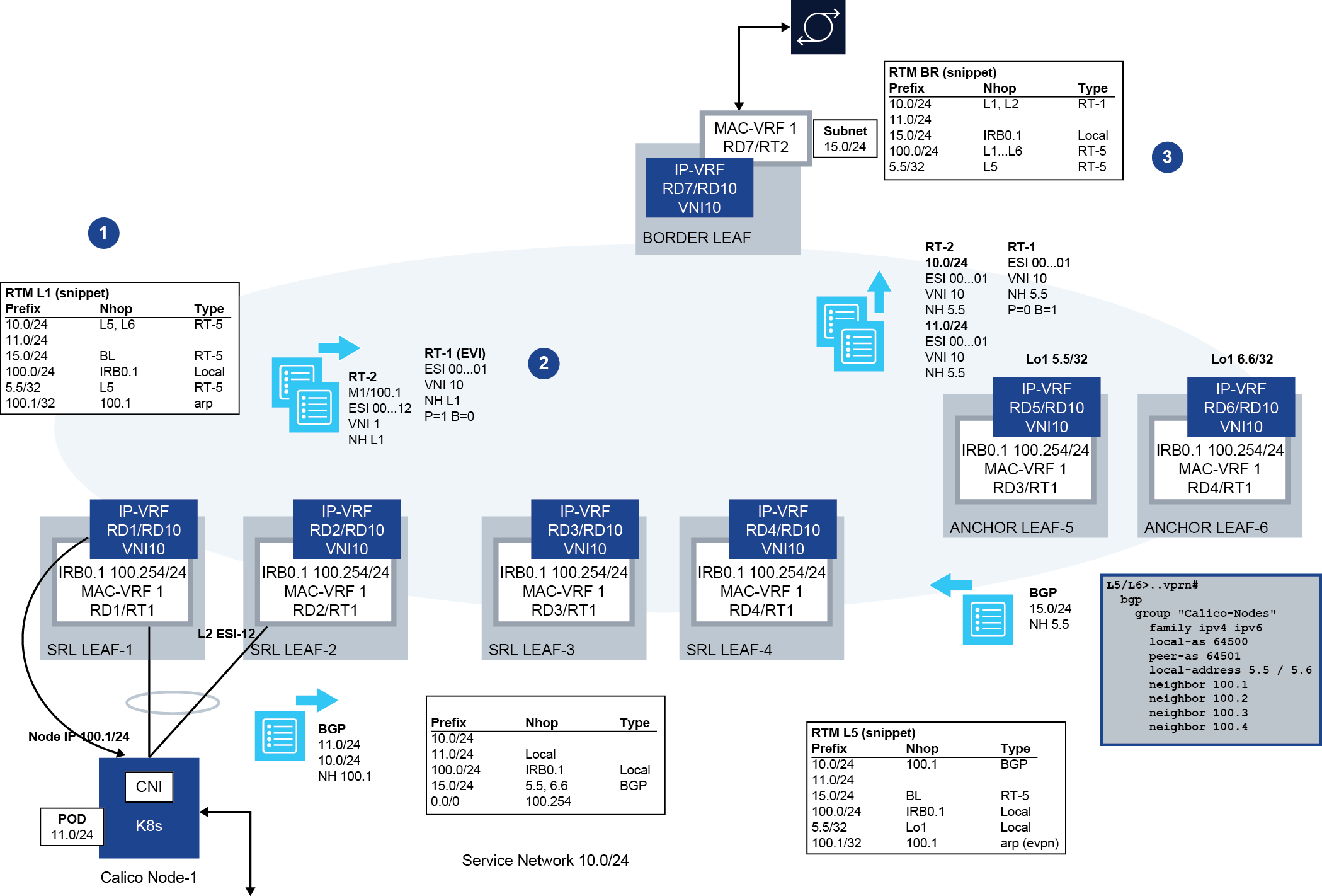
In this example, the centralized routing model is used between all the Kubernetes (K8s) node IPs and the IP-VRF loopbacks on anchor leaf nodes; for example, between Node IP 100.1/24 (Node-1) and 5.5/32 in ANCHOR LEAF-5. Although only one Kubernetes node is depicted in the figure, multiple nodes may be attached to the leaf nodes throughout the data center. By using this model, the BGP configuration is simplified, especially on the Kubernetes nodes, where they can all use the same configuration with a peer to the anchor leaf nodes.
- LEAF-1, LEAF-2, LEAF-5 and LEAF-6 are all configured with the virtual Layer 3 ES ES-1, which uses ESI 00..01, is associated with Node-1 IP 100.1, and is configured as single-active. Node-1 advertises BGP PE-CE routes for 10.0/24 and 11.0/24 to LEAF-5.
- Because LEAF-1 and LEAF-2 have 100.1 in their route table as a local route and they are configured as primary nodes for the ES, they advertise AD per-EVI routes for ES-1 with P = 1. Anchor LEAF-5 and LEAF-6 are configured as non-primary, so even if they have 100.1 in their route table, they advertise their AD per-EVI routes with P = 0 and B = 1 as backup nodes for ES-1. When for example LEAF-5 receives the BGP PE-CE routes from Node-1, it re-advertises them in EVPN IP prefix routes with ESI 00..01.This is because the BGP PE-CE routes' next-hop matches the IP address in ES-1.
- BORDER LEAF imports the EVPN IP prefix routes with ESI 00..01 and recursively resolves them to the next-hops of all the AD per-EVI routes advertised as primary (P = 1); that is, LEAF-1 and LEAF-2. When receiving traffic to 10.0/24 or 11.0/24, BORDER LEAF load balances the traffic to only LEAF-1 and LEAF-2, as opposed to the anchor leaf nodes.
Configuring Layer 3 Ethernet Segments for IP aliasing
To configure a Layer 3 Ethernet Segment for IP aliasing, you specify the Layer 3 next hop to be associated with an Ethernet Segment (ES). The AD per-ES/EVI routes for the ES are advertised when the specified next-hop address is active in the route table of the IP-VRF with the configured EVI.
The following configures two examples of Layer 3 Ethernet Segments, which are associated with an IPv4 and an IPv6 next-hop, respectively.
A:Leaf-1# info from running system network-instance protocols evpn ethernet-segments
  system {
    network-instance {
      protocols {
        evpn {
          ethernet-segments {
            timers {
              boot-timer 180
              activation-timer 3
            }
            bgp-instance 1 {
              ethernet-segment es_v4_1 {
                type virtual
                admin-state enable
                esi 00:bc:de:00:00:00:00:01:00:04
                multi-homing-mode single-active
                next-hop 6.0.1.254 {
                  evi 1 {
                  }
                }
                df-election {
                  algorithm {
                    type preference
                    preference-alg {
                      preference-value 2
                      capabilities {
                        ac-df exclude
                        non-revertive false
                      }
                    }
                  }
                }
                routes {
                  next-hop use-system-ipv4-address
                  ethernet-segment {
                    originating-ip use-system-ipv4-address
                  }
                }
              }
              ethernet-segment es_v6_1 {
                type virtual
                admin-state enable
                esi 00:bc:de:00:00:00:00:01:00:06
                multi-homing-mode single-active
                next-hop 6:0:1::254 {
                  evi 1 {
                  }
                }
                df-election {
                  algorithm {
                    type preference
                    preference-alg {
                      preference-value 2
                      capabilities {
                        ac-df exclude
                        non-revertive false
                      }
                    }
                  }
                }
                routes {
                  next-hop use-system-ipv4-address
                  ethernet-segment {
                    originating-ip use-system-ipv4-address
                  }
                }
              }
            }
          }
        }
      }
    }
  }
Layer 3 ESs must be configured as type virtual and must be associated with a
next-hop and EVI. When the next-hop IP address is active in an IP-VRF identified by the
configured EVI, the corresponding AD-per-ES and per-EVI routes for the ES are advertised.
If the Layer 3 ES is configured as multi-homing-mode all-active, the DF election
algorithm configuration is irrelevant, because there is no DF and all the nodes are primary
(they all advertise P = 1 in their AD per-EVI routes). However, if configured as
multi-homing-mode single-active, a DF election is computed among all the
nodes advertising the same ESI in the ES route. In this case, the default,
preference, or manual algorithms can be used. The manual
DF election simply controls whether the node is primary or not by configuration.
For example, Leaf-1 is configured as primary, so it advertises an AD per-EVI route with P = 1 irrespective of the other leaf nodes in the ES:
--{ +* candidate shared default }--[ system network-instance protocols evpn ethernet-segments bgp-instance 1 ethernet-segment L3-ES-1 ]--
A:Leaf-1# info
  type virtual
  admin-state enable
  esi 01:20:20:20:01:00:00:00:00:00
  multi-homing-mode single-active
  next-hop 20.20.20.1 {
    evi 2 {
    }
  }
  df-election {
    algorithm {
      type manual
      manual-alg {
        primary-evi-range 2 {
          end-evi 2
        }
      }
    }
  }
However, Leaf-2 in the following example is not configured as primary, so it advertises an AD per-EVI route with P = 0 and B = 1. Therefore, it does not attract traffic to the ES as long as there are primary nodes in the ES.
--{ +* candidate shared default }--[ system network-instance protocols evpn ethernet-segments bgp-instance 1 ethernet-segment L3-ES-1 ]--
A:Leaf-2# info
  type virtual
  admin-state enable
  esi 01:20:20:20:01:00:00:00:00:00
  multi-homing-mode single-active
  next-hop 20.20.20.1 {
    evi 2 {
    }
  }
  df-election {
    algorithm {
      type manual
      manual-alg {
      }
    }
  }
The following example shows the configuration of LEAF-1 and LEAF-2 in the BGP peering to VNF loopback figure. LEAF-5 is configured without any ES and with an IP-VRF that has BGP-EVPN enabled and ecmp greater than or equal to 2, so that it can load-balance traffic to the two leaf nodes attached to the ES.
# LEAF-1 and LEAF-2 configuration of the Ethernet Segment
--{ + candidate shared default }--[ system network-instance protocols evpn ]--
A:leaf1/leaf2# info
  ethernet-segments {
    bgp-instance 1 {
      ethernet-segment L3-ES-1 {
        type virtual
        admin-state enable
        esi 01:01:00:00:00:00:00:00:00:00
        multi-homing-mode all-active
        next-hop 1.1.1.1 {
          evi 2 {
          }
        }
      }
    }
  }

# LEAF-1 IP-VRF configuration, including BGP session to the VNF
--{ + candidate shared default }--[ network-instance ip-vrf-2 ]--
A:leaf1# info
  type ip-vrf
  admin-state enable
  interface irb0.1 {
  }
  interface lo1.1 {
  }
  vxlan-interface vxlan1.2 {
  }
  protocols {
    bgp-evpn {
      bgp-instance 1 {
        admin-state enable
        vxlan-interface vxlan1.2
        evi 2
        ecmp 4
      }
    }
    bgp {
        autonomous-system 64501
        router-id 10.0.0.1
        group PE-CE {
        export-policy all
        import-policy all
        peer-as 64500
      }
        afi-safi ipv4-unicast {
            admin-state enable
        }
      neighbor 1.1.1.1 {
        peer-group PE-CE
        multihop {
          admin-state enable
          maximum-hops 10
        }
        transport {
          local-address 10.0.0.1
        }
      }
    }
    bgp-vpn {
      bgp-instance 1 {
        route-distinguisher {
          rd 1.1.1.1:2
        }
        route-target {
          export-rt target:64500:2
          import-rt target:64500:2
        }
      }
    }
  static-routes {
    route 1.1.1.1/32 {
      next-hop-group NHG-1
    }
  }
  next-hop-groups {
    group NHG-1 {
      nexthop 1 {
        ip-address 10.0.0.1
      }
      nexthop 2 {
        ip-address 10.0.0.2
      }
    }
  }

# LEAF-2 IP-VRF configuration
--{ + candidate shared default }--[ network-instance ip-vrf-2 ]--
A:leaf2# info
  type ip-vrf
  interface irb0.1 {
  }
  vxlan-interface vxlan1.2 {
  }
  protocols {
    bgp-evpn {
      bgp-instance 1 {
        vxlan-interface vxlan1.2
        evi 2
        ecmp 4
      }
    }
    bgp-vpn {
      bgp-instance 1 {
        route-distinguisher {
          rd 2.2.2.2:2
        }
        route-target {
          export-rt target:64500:2
          import-rt target:64500:2
        }
      }
    }
  static-routes {
    route 1.1.1.1/32 {
      next-hop-group NHG-1
    }
  }
  next-hop-groups {
    group NHG-1 {
      nexthop 1 {
        ip-address 20.0.0.1
      }
      nexthop 2 {
        ip-address 20.0.0.1
      }
    }
  }
}
The following shows the route table for one of the subscriber prefixes (11.11.11.11/32) that are advertised from the VNF with a next-hop matching the Layer 3 ES next-hop. For LEAF-1, the route is learned via BGP PE-CE.
# LEAF-1 route table entry
--{ + candidate shared default }--[ network-instance ip-vrf-2 ]--
A:leaf1# info from state route-table ipv4-unicast route 11.11.11.11/32 id 0 route-type bgp route-owner bgp_mgr
  route-table {
    ipv4-unicast {
      route 11.11.11.11/32 id 0 route-type bgp route-owner bgp_mgr {
        metric 0
        preference 170
        active true
        last-app-update 2022-10-19T10:26:51.020Z
        next-hop-group 423577430891
        next-hop-group-network-instance ip-vrf-2
        resilient-hash false
        fib-programming {
          last-successful-operation-type add
          last-successful-operation-timestamp 2022-10-19T10:26:51.021Z
          pending-operation-type none
          last-failed-operation-type none
        }
      }
    }
}# LEAF-2 route table entry
--{ +* candidate shared default }--[ network-instance ip-vrf-2 ]--
A:leaf2# info from state route-table ipv4-unicast route 11.11.11.11/32 id 0 route-type bgp-evpn route-owner bgp_evpn_mgr
route-table {
ipv4-unicast {
route 11.11.11.11/32 id 0 route-type bgp-evpn route-owner bgp_evpn_mgr {
metric 0
preference 170
active true
last-app-update 2022-10-19T10:25:06.199Z
next-hop-group 423577389148
next-hop-group-network-instance ip-vrf-2
resilient-hash false
fib-programming {
last-successful-operation-type add
last-successful-operation-timestamp 2022-10-19T10:25:06.199Z
pending-operation-type none
last-failed-operation-type none
}
}
}
}
--{ +* candidate shared default }--[ network-instance ip-vrf-2 ]--
A:leaf2# info from state route-table next-hop-group 423577389148
route-table {
next-hop-group 423577389148 {
backup-next-hop-group 0
next-hop 0 {
next-hop 423577389136
resolved true
}
next-hop 1 {
next-hop 423577389137
resolved true
}
}
}
--{ +* candidate shared default }--[ network-instance ip-vrf-2 ]--
A:leaf2# show route-table next-hop 423577389136
---------------------------------------------------------------------------------
Next-hop route table of network instance ip-vrf-2
---------------------------------------------------------------------------------
Index : 423577389136
Next-hop : 20.20.20.1
Type : indirect
Subinterface : N/A
Resolving Route : 20.20.20.0/24 (local)Resilient hashing for EVPN IFL
Resilient hashing is supported for EVPN IFL where an IFL route points to a next-hop group (NHG) that contains indirect next hops. The indirect next hops are then resolved by MPLS tunnels.
The resilient hashing feature has "sticky" flows even when flows are rehashed because of newly added or failed links. This feature prevents rerouting of flows that are unaffected by network link failures.
- regular ECMP with EVPN IFL routes
- unequal ECMP with EVPN IFL routes
- combined EVPN IFL and BGP PE-CE weighted ECMP
Resilient hashing is also supported for the addition or removal of next hops.
Resilient hashing and unequal ECMP for EVPN IFL
SR Linux supports combined resilient hashing and unequal ECMP for EVPN IP prefix IFL routes. Both resilient hashing and unequal ECMP can be used on the same prefix.
Configuring resilient hashing and unequal ECMP for EVPN IFL
--{ * candidate shared default }--[ network-instance ip-vrf-2 ]--
A:leaf1# info
    type ip-vrf
    admin-state enable
    ip-load-balancing {
        resilient-hash-prefix 10.10.10.0/24 { // resilient hashing is configured for prefix 10.10.10.0/24
            hash-buckets-per-path 32
            max-paths 2
        }
    }
    interface irb0.1 {
    }
    interface lo1.1 {
    }
    vxlan-interface vxlan1.2 {
    }
    protocols {
        bgp-evpn {
            bgp-instance 1 {
                admin-state enable
                vxlan-interface vxlan1.2
                evi 2
                ecmp 4
                routes {
                    route-table {
                        ip-prefix {
                            evpn-link-bandwidth {
                                advertise {
                                    weight dynamic
                                }
                                weighted-ecmp { // unequal ECMP is configured for EVPN IFL
                                    admin-state enable
                                    max-ecmp-hash-buckets-per-next-hop-group 128
                                }
                            }
                        }
                    }
                }
            }
        }
        bgp {
            autonomous-system 64501
            router-id 1.1.1.1
            afi-safi ipv4-unicast {
                admin-state enable
                multipath {
                    max-paths-level-1 4
                    max-paths-level-2 4
                }
            }
            group PE-CE {
                export-policy all
                import-policy all
                peer-as 64500
                afi-safi ipv4-unicast {
                    ipv4-unicast {
                        link-bandwidth {
                            add-next-hop-count-to-received-bgp-routes 1
                        }
                    }
                }
                timers {
                    connect-retry 1
                    hold-time 9
                    keepalive-interval 3
                    minimum-advertisement-interval 1
                }
            }
            neighbor 20.20.20.1 {
                peer-group PE-CE
                multihop {
                    admin-state enable
                    maximum-hops 10
                }
                transport {
                    local-address 1.1.1.1
                }
            }
        }
        bgp-vpn {
            bgp-instance 1 {
                route-distinguisher {
                    rd 1.1.1.1:2
                }
                route-target {
                    export-rt target:64500:2
                    import-rt target:64500:2
                }
            }
        }
Resilient hashing is configured for the 10.10.10.0/24 prefix using the resilient-hash-prefix parameter. The hash-buckets-per-path parameter indicates the number of times each next hop is repeated in the fill pattern. The max-paths parameter indicates the maximum number of ECMP next hops per route associated with the resilient-hash-prefix. The product of the hash-buckets-per-path and max-paths parameters is the total number of buckets that are used when applying the normalized weights.
Unequal ECMP is configured for the same EVPN IFL prefix using the weighted-ecmp and max-ecmp-hash-buckets-per-next-hop-group parameters.
To configure both resilient hashing and unequal ECMP on the same prefix, the hash-buckets-per-path and max-ecmp-hash-buckets-per-next-hop-group parameters can be set to different values. The hash-buckets-per-path parameter will override max-ecmp-hash-buckets-per-next-hop-group.
- max-paths=16
- hash-buckets-per-path=16
The above values result in the router using 256 hash buckets for the prefix, with an ECMP member cap of 16.
Combined ECMP for BGP PE-CE and EVPN IFL/IP-VPN
SR Linux supports the combination of EVPN IFL, IP-VPN, and BGP PE-CE routes in a single ECMP set or next-hop group. The combination of routes is also supported in unequal ECMP.
Combined ECMP is supported along with IP Aliasing, unequal ECMP and resilient hashing for EVPN IFL routes.
Combined ECMP is represented in a route table as a single route with a combined next-hop group. When at least one of the next hops is coming from a BGP PE-CE route, the resulting route type is BGP.
All possible route combinations for combined BGP PE-CE weighted ECMP shows all the possible route combinations and the resulting route types. The resulting route follows the best path selection result across the BGP owners of the route.
| Route combination | Resulting route type |
|---|---|
|
BGP |
|
BGP |
|
BGP-EVPN |
|
BGP |
bgp-evpn.ecmp[=1..64]bgp-ipvpn.ecmp[=1..64]bgp.multipath.max-paths-level-1[=1..64]
bgp-evpn.ecmp[=10]bgp-ipvpn.ecmp[=12]bgp.multipath.max-paths-level-1[=15]
- If at least one
bgp-evpnis present in the combined route, the maximum number of ECMP paths used is 10. - Else, if at least one
bgp-ipvpnroute is present in the combined route, the maximum number of ECMP paths used is 12. - Else, the maximum number of ECMP paths is 15.
--{ * candidate shared default }--[  ]--
A:srl1# info network-instance ip-vrf
    network-instance ip-vrf {
        protocols {
            bgp-vpn {
                combined-ecmp {
                }
            }
        }
}- Valid routes
- Origin validation state
- Route table PREFERENCE
- BGP local preference
- BGP
AS_PATH - BGP origin
- BGP MED
When multiple routes of the same or different owner for the same prefix are received, the selection is affected by the configuration of combined-ecmp, as indicated in Best path selection for EVPN IFL routes.
Combined ECMP example
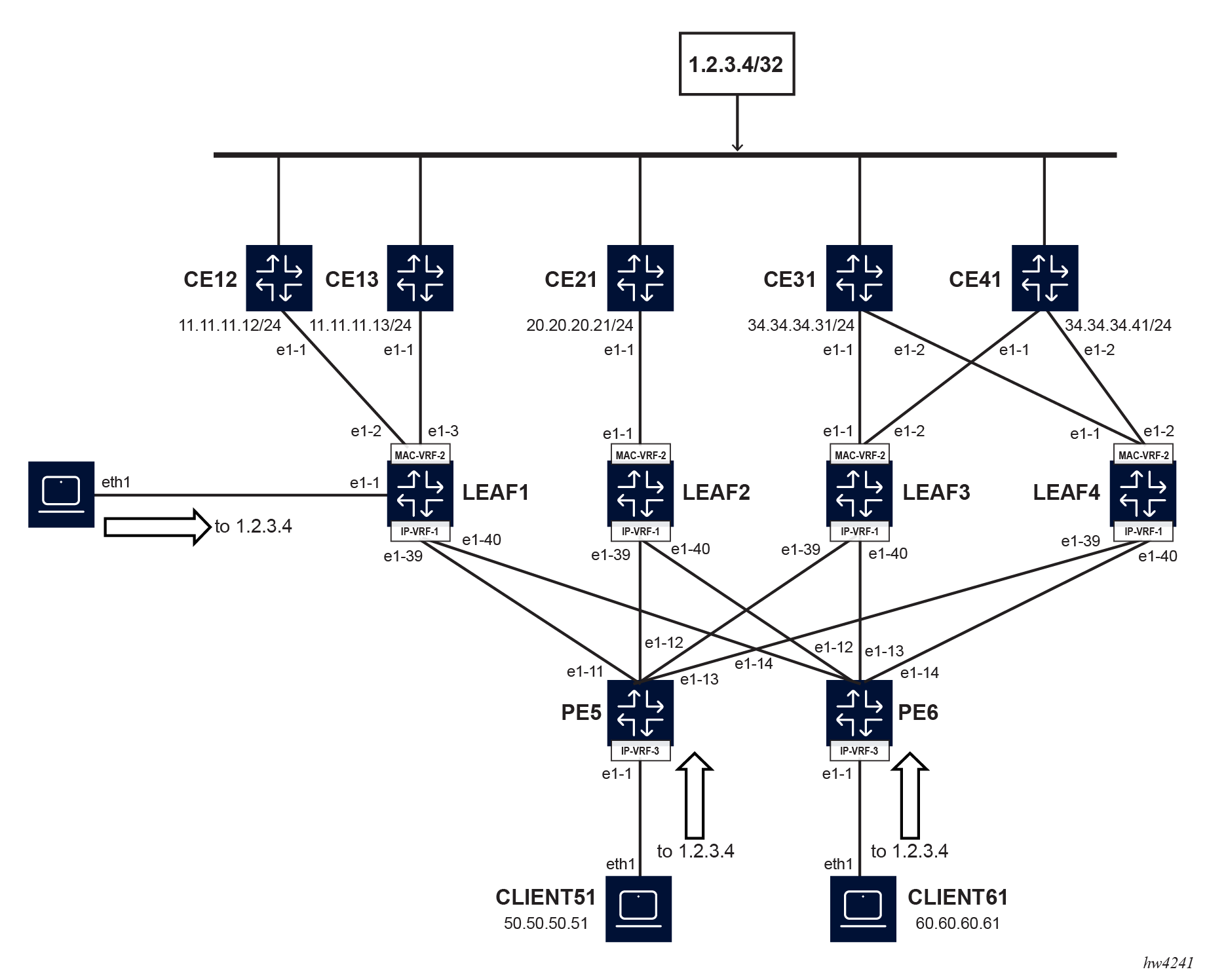
The figure shows that CE12, CE13, CE21, CE31 and CE41 are all connected to the host 1.2.3.4/32 and advertise this in BGP PE-CE to their connected leaf router. Leaf1 receives the 1.2.3.4/32 prefix via BGP and BGP-EVPN. By configuring combined-ecmp, leaf1 can install a single BGP route to 1.2.3.4/32 with a combined next-hop group that includes the PE-CE routes and remote next hops from EVPN IFL routes, with or without weights and with or without ESIs.
--{ * candidate shared default }--[ network-instance IP-VRF-1 ]--
A:srl1# info
    type ip-vrf
    description "IP-VRF-2 EVPN-MPLS uecmp"
    ip-load-balancing {
        resilient-hash-prefix 1.2.0.0/16 {
            hash-buckets-per-path 6
            max-paths 10
        }
    }
    interface ethernet-1/1.1 {
    }
    interface irb0.1 {
    }
    interface lo0.1 {
    }
    protocols {
        bgp-evpn {
            bgp-instance 1 {
                encapsulation-type mpls
                evi 1
                ecmp 64
                mpls {
                    next-hop-resolution {
                        allowed-tunnel-types [
                            ldp
                            sr-isis
                        ]
                    }
                }
                routes {
                    route-table {
                        ip-prefix {
                            evpn-link-bandwidth {
                                advertise {
                                    weight dynamic
                                }
                                weighted-ecmp {
                                    admin-state enable
                                    max-ecmp-hash-buckets-per-next-hop-group 64
                                }
                            }
                        }
                    }
                }
            }
        }
        bgp {
            admin-state enable
            autonomous-system 64500
            router-id 1.1.1.1
            ebgp-default-policy {
                import-reject-all false
                export-reject-all false
            }
            afi-safi ipv4-unicast {
                admin-state enable
                multipath {
                    maximum-paths 64
                }
            }
            trace-options {
                flag packets {
                    modifier detail
                }
                flag update {
                    modifier detail
                }
            }
            group pe-ce {
                multihop {
                    admin-state enable
                    maximum-hops 10
                }
                afi-safi ipv4-unicast {
                    ipv4-unicast {
                        link-bandwidth {
                            add-next-hop-count-to-received-bgp-routes 1
                        }
                    }
                }
                timers {
                    connect-retry 1
                    minimum-advertisement-interval 1
                }
                trace-options {
                    flag update {
                        modifier detail
                    }
                }
                transport {
                    local-address 1.1.1.1
                }
            }
            neighbor 11.11.11.12 {
                peer-as 64512
                peer-group pe-ce
            }
            neighbor 11.11.11.13 {
                peer-as 64513
                peer-group pe-ce
            }
        }
        bgp-vpn {
            combined-ecmp {
            }
            bgp-instance 1 {
            }
        }
}--{ + candidate shared default }--[ network-instance IP-VRF-1 ]--
A:leaf1# show route-table ipv4-unicast prefix 1.2.3.4/32
---------------------------------------------------------------------------------------------------------
IPv4 unicast route table of network instance IP-VRF-1
---------------------------------------------------------------------------------------------------------
+------------+----+--------+----------+--------+----------+--------+------+-----------------+-----------+
| Prefix | ID | Route | Route | Active | Origin | Metric | Pref | Next-hop (Type) | Next-hop |
| | | Type | Owner | | Network | | | | Interface |
| | | | | | Instance | | | | |
+============+====+========+==========+========+==========+========+======+=================+===========+
| 1.2.3.4/32 | 0 | bgp | bgp_mgr | True | IP-VRF-1 | 0 | 170 | 11.11.11.0/24 ( | irb0.1 |
| | | | | | | | | indirect/local) | irb0.1 |
| | | | | | | | | 11.11.11.0/24 ( | |
| | | | | | | | | indirect/local) | |
| | | | | | | | | 100.0.0.2/32 ( | |
| | | | | | | | | indirect/ldp) | |
| | | | | | | | | 100.0.0.3/32 ( | |
| | | | | | | | | indirect/ldp) | |
| | | | | | | | | 100.0.0.4/32 ( | |
| | | | | | | | | indirect/ldp) | |
+------------+----+--------+----------+--------+----------+--------+------+-----------------+-----------+
---------------------------------------------------------------------------------------------------------
-----------------------------------------------------------------------------------------------------------{ + candidate shared default }--[ network-instance IP-VRF-1 ]--
A:leaf1# info from state route-table ipv4-unicast route 1.2.3.4/32 id 0 route-type bgp route-owner bgp_mgr origin-network-instance IP-VRF-1
leakable false
metric 0
preference 170
active true
last-app-update "2024-07-02T09:06:02.838Z (an hour ago)"
next-hop-group 347400906964
next-hop-group-network-instance IP-VRF-1
resilient-hash true
fib-programming {
suppressed false
last-successful-operation-type modify
last-successful-operation-timestamp "2024-07-02T09:06:02.839Z (an hour ago)"
pending-operation-type none
last-failed-operation-type none
}
--{ + candidate shared default }--[ network-instance IP-VRF-1 ]--
A:leaf1# info from state route-table next-hop-group 347400906964
backup-next-hop-group 0
fib-programming {
last-successful-operation-type modify
last-successful-operation-timestamp "2024-07-02T09:06:02.839Z (an hour ago)"
pending-operation-type none
last-failed-operation-type none
}
next-hop 0 {
next-hop 347400907006
resolved true
}
next-hop 1 {
next-hop 347400907007
resolved true
}
next-hop 2 {
next-hop 347400906982
resolved true
}
next-hop 3 {
next-hop 347400906999
resolved true
}
next-hop 4 {
next-hop 347400906996
resolved true
}
--{ + candidate shared default }--[ network-instance IP-VRF-1 ]--
A:leaf1# info from state route-table next-hop {347400907006,347400907007,347400906982,347400906999,347400906996}
next-hop 347400907006 {
type indirect
ip-address 11.11.11.12
resolving-route {
ip-prefix 11.11.11.0/24
route-type local
route-owner net_inst_mgr
}
}
next-hop 347400907007 {
type indirect
ip-address 11.11.11.13
resolving-route {
ip-prefix 11.11.11.0/24
route-type local
route-owner net_inst_mgr
}
}
next-hop 347400906982 {
type indirect
ip-address 100.0.0.2
resolving-tunnel {
ip-prefix 100.0.0.2/32
tunnel-type ldp
tunnel-owner ldp_mgr
}
mpls {
pushed-mpls-label-stack [
1000
]
}
}
next-hop 347400906999 {
type indirect
ip-address 100.0.0.3
resolving-tunnel {
ip-prefix 100.0.0.3/32
tunnel-type ldp
tunnel-owner ldp_mgr
}
mpls {
pushed-mpls-label-stack [
1002
]
}
}
next-hop 347400906996 {
type indirect
ip-address 100.0.0.4
resolving-tunnel {
ip-prefix 100.0.0.4/32
tunnel-type ldp
tunnel-owner ldp_mgr
}
mpls {
pushed-mpls-label-stack [
1001
]
}
}