IEEE 1588 PTP
PTP is a timing-over-packet protocol defined in the IEEE 1588 Version 2 of the standard, published in 2008. The standard was revised to Version 2.1 in 2019.
PTP provides the capability to synchronize network elements to a stratum-1 clock, PRC traceable source, or PRTC traceable source over a network that may or may not be PTP-aware. PTP is a standards-based protocol, has low bandwidth requirements, can transport frequency, time, and phase, and can potentially provide better performance.
The following are the basic types of PTP clocks:
-
ordinary clock
-
boundary clock
-
end-to-end transparent clock
-
peer-to-peer transparent clock
The boundary clock and ordinary clock can be used for frequency and time distribution, depending on the selected profile.
The following table describes PTP clock type support.
| Platform | Ordinary clock | Boundary clock | Transparent clock | ||
|---|---|---|---|---|---|
| timeReceiver | timeTransmitter | End-to-end | Peer-to-peer | ||
|
7220 IXR-D5; model 3HE17735AB (w/Timing) |
Not supported |
Not supported |
✓ |
Not supported |
Not supported |
| 7250 IXR-X3b |
Not supported |
Not supported |
✓ |
Not supported |
Not supported |
The ordinary clock timeTransmitter, ordinary clock timeReceiver, and boundary clock communicate with neighboring IEEE 1588 clocks. These neighbor clocks can be ordinary clock timeTransmitters, ordinary clock timeReceivers, or boundary clocks. The communication can be based on either unicast IPv4 sessions transported through IP interfaces or multicast Ethernet transported through Ethernet ports.
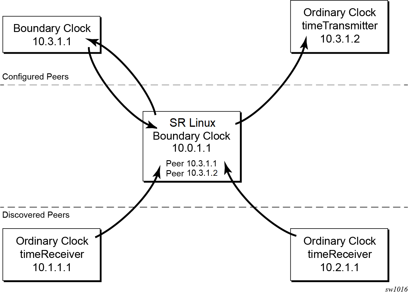
For unicast IP sessions, the external clocks are labeled ‟peers”. There are two types of peers: configured and discovered. An ordinary clock timeReceiver or a boundary clock should have configured peers for each PTP neighbor clock from which it may accept synchronization information. The router initiates unicast sessions with all configured peers. An ordinary clock timeTransmitter or boundary clock accepts unicast session requests from external peers. If the peer is not a configured peer, it is considered a discovered peer. An ordinary clock timeTransmitter or boundary clock can deliver synchronization information toward discovered peers. The following figure shows the relationship of various neighbor clocks that use unicast IP sessions to communicate with an SR Linux router configured as a boundary clock with two configured peers.
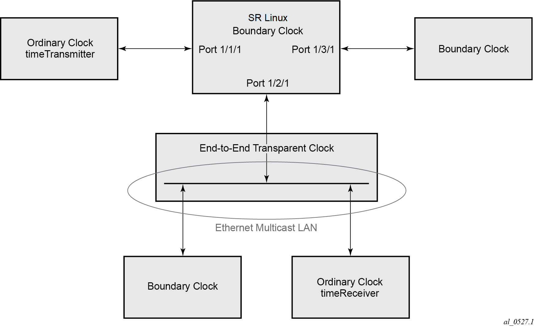
For multicast Ethernet operation, the router listens for and transmits PTP messages using the configured multicast MAC address. Neighbor clocks are discovered when messages are received through an enabled Ethernet port. An ordinary clock timeTransmitter, ordinary clock timeReceiver, and a boundary clock support more than one neighbor PTP clock connecting into a single port. This may be encountered with the deployment of an Ethernet multicast LAN segment between the local clock and the neighbor PTP ports using an end-to-end transparent clock or an Ethernet switch. The Ethernet switch is not recommended because of the introduction of packet delay variation (PDV) and the potential degradation of performance, but it can be used if appropriate for the application.
The following figure shows the relationship of various neighbor clocks using multicast Ethernet sessions to communicate with an SR Linux router configured as a boundary clock. The SR Linux router has three ports configured for multicast Ethernet communications. Port 1/2/1 of the SR Linux router shows a connection where two neighbor clocks connect to a single port of the SR Linux router through an end-to-end transparent clock.
The ordinary clock timeTransmitter, ordinary clock timeReceiver, and boundary clock support PTP operation over either unicast IPv4 or multicast Ethernet at any one time.
The IEEE 1588 standard includes the concept of PTP profiles. These profiles are defined by industry groups or standards bodies that define how IEEE 1588 is used for an application.
The 7220 IXR-D5 supports the following profiles:
-
G.8275.1 (itug8275dot1)
This profile is restricted to PTP over Ethernet and restricts PTP ports to be physical interfaces.
-
G.8275.2 (itug8275dot2)
This profile is restricted to PTP over IP and restricts PTP ports to be PTP peers.
When the 7220 IXR-D5 receives an Announce message from one or more configured ports, it executes a Best timeTransmitter Clock Algorithm (BTCA) to determine the state of communication between it and its neighbors. The system uses the BTCA to create a hierarchical topology allowing the flow of synchronization information from the grandmaster clock through the network to all boundary and timeReceiver clocks. Each profile has a dedicated BTCA.
If the profile setting for the clock is itug8275dot1, the precedence order for the best timeTransmitter selection algorithm is very similar to that used with the default profile. It ignores the priority1 parameter, includes a local-priority parameter, and includes the ability to force a port to never enter timeReceiver state (master-only). The precedence is as follows:
-
clockClass
-
clockAccuracy
-
PTP variance (offsetScaledLogVariance)
-
priority2
-
localPriority
-
clockIdentity
-
stepsRemoved from the grandmaster
The following table describes the local parameter settings when the profile setting for the clock is itug8275dot1.
| Parameter | Value and description |
|---|---|
|
clock-identity |
Chassis MAC address following the guidelines of 7.5.2.2.2 of IEEE 1588 |
|
clock-class |
6 — local clock is using a time reference from a GNSS receiver 7 — local clock is in holdover after losing time reference from the local GNSS receiver for no more than ten minutes 135 - local clock is configured as a boundary clock and in holdover; the boundary clock was previously locked to a grandmaster clock with a clock class of 6 and is still considered to be within the holdover specification 165 — local clock is configured as a boundary clock and in holdover; the boundary clock was previously locked to a grandmaster clock with a clock class of 6 and is considered to be outside of the holdover specification 248 — local clock is configured as boundary clock |
|
clock-accuracy |
0xFE — unknown 0x21 — when using a time reference from a GNSS receiver |
|
offset-scaled-log-variance |
0xFFFF — not computed 0x4e5d (1.8E-15) — when using a time reference from a GNSS receiver |
If the profile setting for the clock is itug8275dot2, the precedence order for the best timeTransmitter selection algorithm is very similar to that used with the itug8275dot1 profile. It ignores the priority1 parameter, includes a localPriority parameter, and includes the ability to force a port to never enter timeReceiver state (master-only). The precedence is as follows:
-
clockClass
-
clockAccuracy
-
PTP variance (offsetScaledLogVariance)
-
priority2
-
localPriority
-
clockIdentity
-
stepsRemoved from the grandmaster
If the two clocks being compared have a clockClass of less than 128, the comparison of the clockIdentity is skipped. Skipping the comparison of the clockIdentity is the normal case because the vast majority of clocks used as grandmasters advertise a clockClass of less than 128.
The following table describes the 7220 IXR local parameter settings when the profile setting for the clock is itug8275dot2.
| Parameter | Value and description |
|---|---|
|
clockIdentity |
Chassis MAC address following the guidelines of 7.5.2.2.2 of IEEE 1588 |
|
clockClass |
6 — local clock is using a time reference from a GNSS receiver 7 — local clock is configured as a grandmaster clock and in holdover after losing time reference from the local GNSS receiver for no more than ten minutes 135 - local clock is configured as a boundary clock in holdover; the boundary clock was previously locked to a grandmaster clock with a clock class of 6 and is still considered to be within the holdover specification 165 — local clock is configured as a boundary clock in holdover; the boundary clock was previously locked to a grandmaster clock with a clock class of 6 and is considered to be outside of the holdover specification 248 — local clock is configured as a grandmaster clock or boundary clock in free-run mode 255 — local clock is configured as an ordinary clock timeReceiver |
|
clockAccuracy |
0xFE — unknown 0x21 — when using a time reference from a GNSS receiver |
|
offsetScaledLogVariance |
0xFFFF — not computed 0x4e5d (1.8E-15) — when using a time reference from a GNSS receiver |
See for more information about the G.8275.2 profile.
There is a limit to the number of external PTP clocks from which the ordinary clock timeReceiver or boundary clock requests unicast service. There is also a limit to the number of external PTP clocks to which the ordinary clock timeTransmitter or boundary clock grants unicast service. An association where the boundary clock has a symmetric relationship with another boundary clock (they both have the other as a configured peer) consumes a request and a grant unicast service in each router.
There are limits to the maximum transmitted and received event message rates supported in the router. Each unicast IP service established consumes a portion of one of the unicast message limits. When either limit is reached, additional unicast service requests are refused by sending a grant response with zero in the duration field. See the scaling guide for the appropriate release for the specific unicast message limits related to PTP.
Multicast messages are not considered when validating the unicast message limit. When multicast messaging on Ethernet ports is enabled, you need to monitor the PTP load to ensure that the load does not exceed the limits. The show platform control detail command identifies the load of the PTP software process. If the capacity usage reaches 100%, the PTP software process on the router is at its limit of transmitting and receiving PTP packets.
Because you cannot control the amount of PTP messaging that is being received over the Ethernet ports, use the following statistics commands to identify the source of the message load. Statistics shown for PTP ports are associated with Ethernet-encapulated PTP (G.8275.1 profile) and statistics for PTP peers are associated with IP-encapulated PTP (G.8275.2 profile).
-
info from state system sync ptp instance <instance> default-ds statistics to display aggregate statistics
-
info from state system sync ptp instance <instance> port-ds-interface-list <port-index> statistics to display total messages for a specific PTP port
- info from state system sync ptp instance <instance> port-ds-cfg-ip-list <port-index> statistics to display statistics for configured IP peers
- info from state system sync ptp instance <instance> port-ds-dsc-ip-list <port-index> statistics to display statistics for discovered IP peers
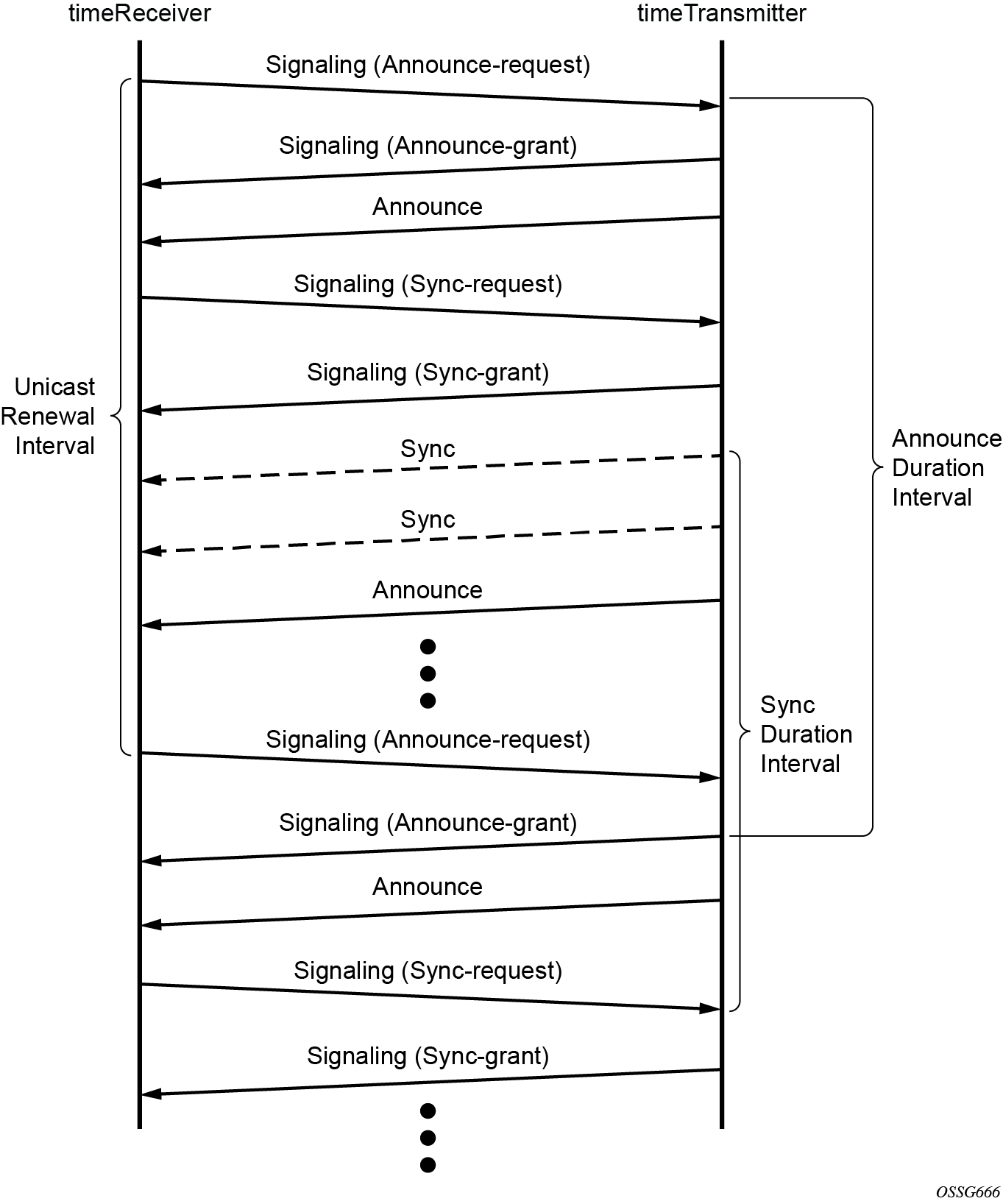
The following figure shows the unicast negotiation procedure performed between a timeReceiver and a peer clock that is selected to be the timeTransmitter clock. The timeReceiver clock requests Announce messages from all peer clocks but only requests Sync and Delay_Resp messages from the clock selected to be the timeTransmitter clock.
PTP clock synchronization
The IEEE 1588 standard synchronizes the frequency and time from a timeTransmitter clock to one or more timeReceiver clocks over a packet stream. This packet-based synchronization standard defines transport to use UDP/IP with unicast or Ethernet with multicast. See PTP capabilities for information about supported PTP encapsulation types.
As part of the basic synchronization timing computation, several event messages are defined for synchronization messaging between the PTP timeReceiver clock and PTP timeTransmitter clock. A one-step or two-step synchronization operation can be used, with the two-step operation requiring a follow-up message after each synchronization message.
During startup, the PTP timeReceiver clock receives the synchronization messages from the PTP timeTransmitter clock before a network delay calculation is made. Before any delay calculation, the delay is assumed to be zero. A drift compensation is activated after several synchronization message intervals occur. The expected interval between the reception of synchronization messages is configurable.
The following figure shows the basic synchronization timing computation between the PTP timeReceiver clock and PTP best timeTransmitter. This figure illustrates the offset of the timeReceiver clock referenced to the best timeTransmitter signal during startup.
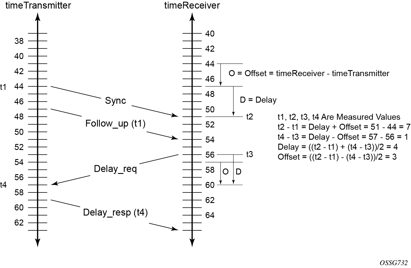
When using IEEE 1588 for distribution of a frequency reference, the timeReceiver calculates a message delay from the timeTransmitter to the timeReceiver based on the timestamps exchanged. A sequence of these calculated delays contain information of the relative frequencies of the timeTransmitter clock and timeReceiver clock but has a noise component related to the PDV experienced across the network. The timeReceiver must filter the PDV effects to extract the relative frequency data, then adjust the timeReceiver frequency to align with the timeTransmitter frequency.
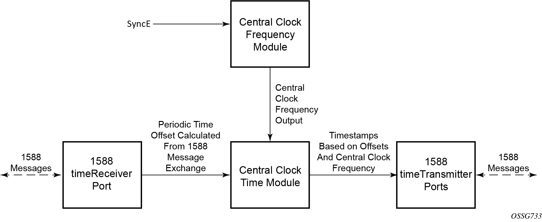
When using IEEE 1588 for distribution of time, SR Linux uses the four timestamps exchanged using the IEEE 1588 messages to determine the offset between the SR Linux time base and the external timeTransmitter clock time base. SR Linux determines the offset adjustment and, in between these adjustments, maintains the progression of time using the frequency from the central clock of the node. This allows time to be maintained using a Synchronous Ethernet input source even if the IEEE 1588 communications fail. When using IEEE 1588 for time distribution, the central clock should at a minimum have the PTP input reference enabled.
The following figure shows a logical model for using PTP/1588 for network synchronization.
Performance considerations
Although IEEE 1588 can be used on a network that is not PTP-aware, the use of PTP-aware network elements (boundary clocks) within the packet switched network improves synchronization performance by reducing the impact of PDV between the grandmaster clock and the timeReceiver clock. When IEEE 1588 is used to distribute high accuracy time, such as for mobile base station phase requirements, the network architecture requires the deployment of PTP awareness in every device between the grandmaster clock and the mobile base station timeReceiver.
In addition, performance is improved by the removal of any PDV caused by internal queuing within the boundary clock or timeReceiver clock. This is accomplished with hardware that can detect and time stamp the IEEE 1588 packets at the Ethernet interface. This capability is referred to as port-based time stamping. The SR Linux platforms that are 1588-capable support port-based time stamping.
Port-based timestamping of PTP messages
To meet the stringent performance requirements of PTP mobile network applications, the 1588 packets must be time-stamped at the ingress and egress ports. This requires the use of 1588 port-based timestamping on the ports handling the PTP messages. This avoids any possible PDV that may be introduced between the port and the CPM. The ability to timestamp in the interface hardware is critical to achieve optimal performance. All PTP-capable ports support port-based timestamping.
PTP capabilities
The following table describes PTP encapsulation type and PTP profile support.
| Platform | PTP encapsulation type | PTP profile | ||
|---|---|---|---|---|
| IPv4 | Ethernet | G.8275.1 (Ethernet only) | G.8275.2 (IPv4 only) | |
|
7220 IXR-D5 |
✓ |
✓ |
✓ |
✓ |
| 7250 IXR-X3b |
✓ |
✓ |
✓ |
✓ |
With the G.8275.2 profile, every PTP message exchange between the router and an external 1588 clock must be established using the Unicast Negotiation procedures. The router allows the configuration of the message rate to be requested from external 1588 clocks. The router also supports a range of message rates that it grants to requests received from the external 1588 clocks.
The following table describes the ranges for the request and grant rates.
| Message type | Rates requested by SR Linux | Rates granted by SR Linux | ||
|---|---|---|---|---|
| Min | Max | Min | Max | |
|
Announce |
1 packet per 16 seconds |
8 packets per second |
1 packet per 16 seconds |
8 packets per second |
|
Sync |
1 packet per second |
64 packets per second |
1 packet per second |
64 packets per second |
|
Delay_Resp |
1 packet per second |
64 packets per second |
1 packet per second |
64 packets per second |
State and statistics data for each timeTransmitter clock are available to assist in the detection of failures or unusual situations.
PTP boundary clock
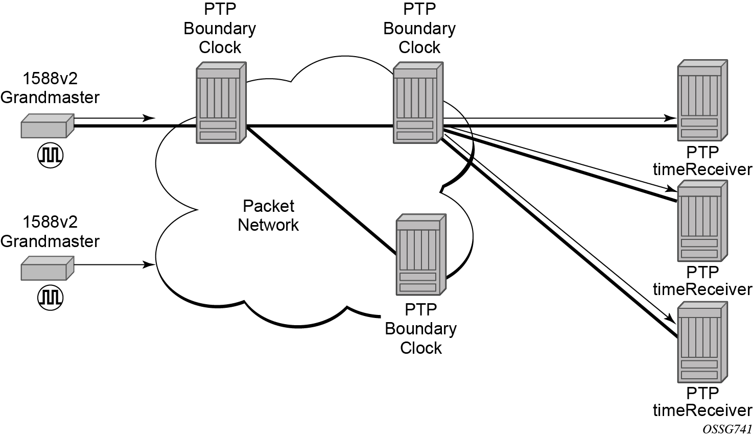
IEEE 1588 can function across a packet network that is not PTP-aware. However, the performance may be unpredictable. PDV across the packet network varies with the number of hops, link speeds, utilization rates, and the inherent behavior of the routers. By using routers with boundary clock functionality in the path between the grandmaster clock and the timeReceiver clock, one long path over many hops is split into multiple shorter segments, allowing better PDV control and improved timeReceiver performance. This allows PTP to function as a valid timing option in more network deployments and allows for better scalability and increased robustness in specific topologies, such as rings.
Boundary clocks can simultaneously function as a PTP timeReceiver of an upstream grandmaster (ordinary clock) or boundary clock, and as a PTP timeTransmitter of downstream timeReceivers (ordinary clock) and boundary clocks, as shown in the following figure. The time scale recovered in the timeReceiver side of the boundary clock is used by the timeTransmitter side of the boundary clock. This allows time to be distributed across the boundary clock.
ITU-T G.8275.2 profile and APTS
SR Linux supports Recommendation ITU-T G.8275.2, which, similar to Recommendation ITU-T G.8275.1, specifies the architecture that allows the distribution of time and phasing. ITU-T G.8275.1 supports full timing support from the network and ITU-T G.8275.2 supports both partial timing support (PTS) and APTS.
When the SR Linux router is configured to use the G.8275.1 or G.8275.2 profile, it uses an alternate BTCA for best timeTransmitter clock selection. This BTCA includes a PTP dataset comparison that is defined in IEEE 1588-2008, but with the following differences:
- the priority1 attribute value is removed from the dataset comparison
- the master-only parameter value must be considered
- multiple active grandmaster clocks are allowed; therefore, the BTCA selects the nearest clock of equal quality
- a port-level local-priority attribute value is used to select a timeReceiver port if two ports receive an Announce message. This attribute is used as a tiebreaker in the dataset comparison algorithm if all other previous attributes of the datasets being compared are equal.
- the local-priority parameter value is considered for the default dataset
When the PTP clock is configured to use the G.8275.2 profile without GNSS configured, the clock operates using PTS. Only nodes that include an embedded GNSS can operate using APTS.
The following table describes the mapping between ITU-T G.8275.2 and PTP clock types. T-BC-A and T-TSC-A clocks are applicable to APTS.
| Clock type from ITU-T G.8275.2 | Description | Clock type from IEEE 1588 |
|---|---|---|
|
T-GM |
timeTransmitter ordinary clock (clock with a single PTP port; cannot be a timeReceiver from another PTP clock) |
Ordinary clock |
|
timeTransmitter boundary clock (clock with multiple PTP ports; cannot be a timeReceiver from another PTP clock) |
Boundary clock1 |
|
|
T-BC-P (partial) |
Boundary clock (may become a grandmaster clock, or may be a timeReceiver from another PTP clock) |
Boundary clock |
|
T-BC-A (assisted partial) |
Boundary clock assisted by a local time reference that is used as a primary source of time (may become a grandmaster clock, or may be a timeReceiver to another PTP clock) |
Boundary clock2 |
|
T-TSC-P (partial) |
Always timeReceiver; single-port ordinary clock |
Ordinary clock |
|
PTP clock at the end of the PTP synchronization chain; multiple port clock |
Boundary clock1 |
|
|
T-TSC-A (assisted partial) |
Always timeReceiver; single-port ordinary clock assisted by a local time reference that is used as a primary source of time |
Ordinary clock2 |
|
PTP clock at the end of the PTP synchronization chain; multiple-port clock assisted by a local time reference that is used as a primary source of time |
PTP message encapsulations
The SR Linux implementation of PTP over Ethernet provides support for PTP within raw Ethernet (no VLAN header) encapsulation.
SR Linux platforms that support PTP over IPv4 support the following encapsulations:
- PTP within UDP/IPv4 within raw Ethernet (no VLAN header)
No other encapsulations are supported.
1PPS interfaces
The 1PPS interfaces are supported in SR Linux. These interfaces output the recovered signal from the system clock when PTP is enabled.
Configuration guidelines and restrictions for PTP
-
The PTP timeReceiver and timeTransmitter capabilities are available on all Ethernet ports, except the management port and 7220 IXR-D5 SFP+ ports 33 and 34
-
1PPS interface signals are enabled when both PTP and the 1 PPS interface are enabled. 1PPS interface signals can be used after the system is configured to use PTP as a reference and is locked to PTP.