Priority-based Flow Control (PFC)
Priority-based flow control (PFC), based on the IEEE 802.1Qbb standard, is a link-level flow control mechanism that extends the capabilities of IEEE 802.3x-based Ethernet flow control. With the 802.3x standard, when a receiving interface experiences congestion, it can send a pause frame to the transmitting interface to suspend the flow of traffic for all priority values. PFC operates using a similar pause frame, but unlike 802.3x, the PFC pause frame can encode a different pause time for each of the eight different 802.1p CoS values. The pause time is measured in quanta, which is the time to transmit 512 bits (and where a quanta value of 0 indicates to unpause).
The main application of PFC is to support Fibre channel over Ethernet (FCoE). With FCoE, the FC-2 Fibre Channel layer assumes a lossless medium. When a receiving interface exceeds its buffer threshold, the interface sends pause frames to the transmitter to stop it from sending more FCoE frames.
PFC can be autonegotiated using the Data Center Bridging Capability Exchange (DCBX) protocol or can be statically enabled at both ends. SR Linux supports only statically-enabled PFC, and only for unicast traffic.
At ingress, the PFC feature can be enabled per interface only, while at egress, PFC can be enabled or disabled for each egress queue.
On an interface, PFC and traditional 802.3x-based Ethernet flow control (interface ethernet flow-control) are mutually exclusive.
The following sections provide platform-specific implementation details for PFC:
- Ingress PFC operation on the traffic-receiving interface (7250 IXR-6e/10e/X)
- Egress PFC operation on the traffic-transmitting interface (7250 IXR-6e/10e/X)
- Ingress PFC operation on the traffic-receiving interface (7220 IXR-H4/D4/D5)
- Egress PFC operation on the traffic-transmitting interface (7220 IXR-H4/D4/D5)
Ingress PFC operation on the traffic-receiving interface (7250 IXR-6e/10e/X)
On 7250 IXR-6e/10e/X platforms, the operation of PFC on a traffic-receiving interface is a function of the following elements:
Mapping of forwarding classes to PFC queues
The incoming packets are mapped to one of eight PFC queues based on the forwarding class index of the packet, as determined by the applicable subinterface-level classification policy. The following table shows the mapping of forwarding class index values to PFC queue values.
| Forwarding class index | PFC queue |
|---|---|
| 0 | 0 |
| 1 | 1 |
| 2 | 2 |
| 3 | 3 |
| 4 | 4 |
| 5 | 5 |
| 6 | 6 |
| 7 | 7 |
Receive buffer sections
The whole receive buffer is divided into two sections: one lossy and one lossless. The PFC queues draw buffers from the lossless section, which is in turn subdivided into an interface section containing individual interface buffers and a PFC buffer reservation section, as shown in the following figure.
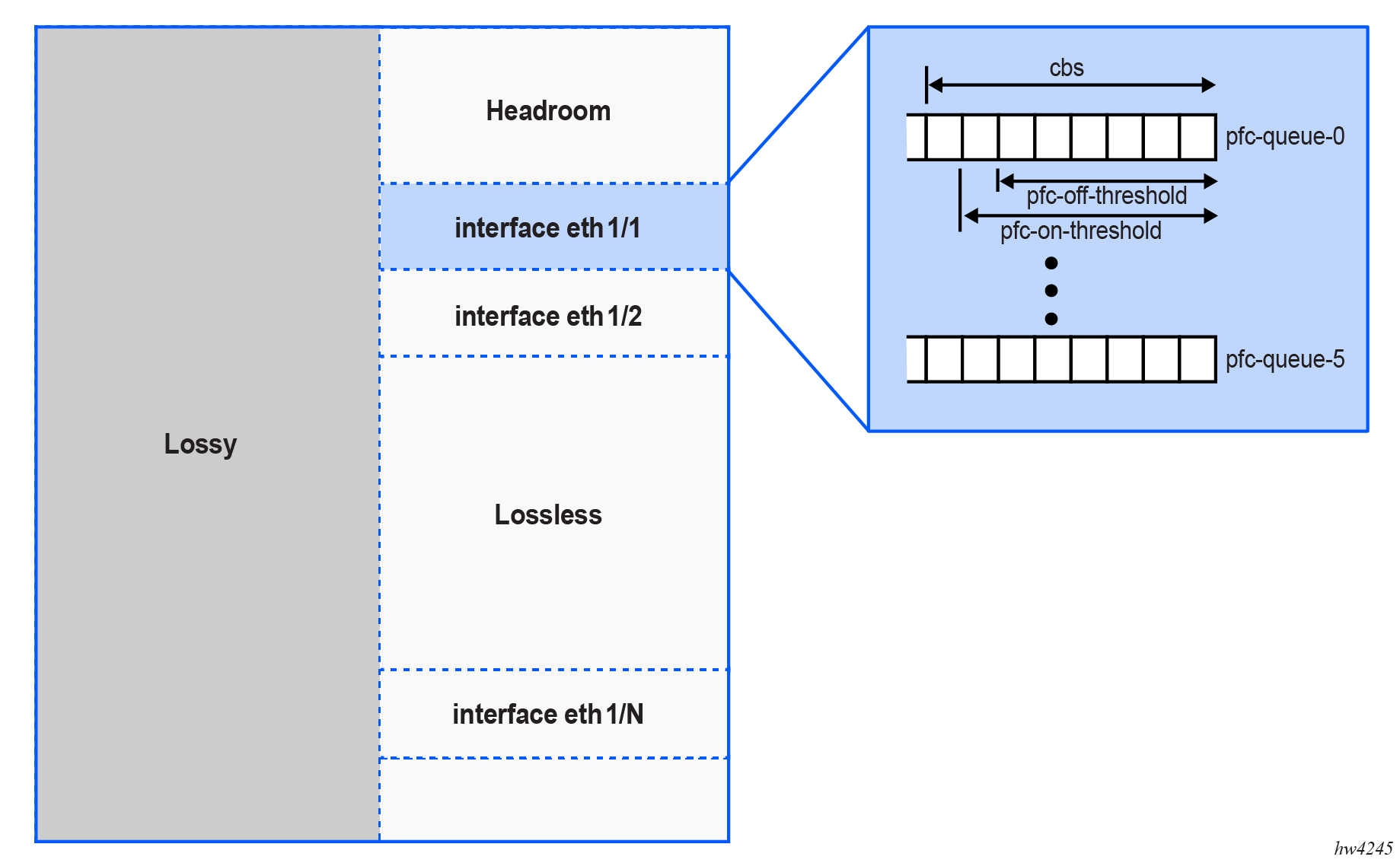
The interface section serves eight PFC queues, each having a length equal to the committed burst size (CBS), as defined in the buffer allocation profile.
The PFC buffer reservation section is shared by all interfaces and is primarily intended to accommodate in-flight frames (the frames that are received after the PFC pause frame is generated to the sender, but the sender has not yet reacted to it). On 7250 IXR-6e/10e/X platforms, the size of the PFC buffer reservation section is fixed at 100 MB. To prevent the exhaustion of the PFC buffer reservation section between individual interfaces, the maximum-pfc-reserved-share-percentage parameter (or alternatively, maximum-pfc-reserved-share-bytes) is configurable per PFC queue in the buffer allocation profile, which is assigned at the interface level.
Pause frame generation thresholds (percentage of CBS)
The system generates PFC pause frames for a PFC queue after the queue length reaches the pfc-on-threshold value, and stops generating PFC pause frames after the queue length falls under the pfc-off-threshold value. Both values are defined in the buffer allocation profile as a percentage of the CBS.
Egress PFC operation on the traffic-transmitting interface (7250 IXR-6e/10e/X)
The operation of PFC on the traffic-transmitting (and therefore PFC pause frame-receving) interface is a function of the following elements:
Pause frame to egress queue mapping
The mapping of PFC pause frame priorities to egress queues is configurable in the PFC mapping profile. This profile determines which egress queues react to which PFC pause frame priorities. A single PFC pause frame priority can be configured per egress queue. When the transmitting system receives a PFC pause frame from a downstream receiver, it stops transmitting from the applicable queue. If the given egress queue is configured to react to a PFC priority of 1, it does so as long as the PFC pause frame contains a PFC priority of 1, whether or not other priorities are present.
Deadlock recovery
SR Linux also supports a deadlock recovery mechanism, which prevents permanent shutdown of the egress interface based on deadlock timers configured in the PFC mapping profile. When the deadlock timers are configured, if a queue receives PFC pause frames that prevent it from forwarding traffic for longer than the defined detection period, the system ignores the PFC pause frames on the queue and resumes forwarding traffic for a defined recovery period.
Ingress PFC operation on the traffic-receiving interface (7220 IXR-H4/D4/D5)
On 7220 IXR-H4/D4/D5 platforms, the operation of PFC on a traffic-receiving interface is a function of the following elements:
Mapping of dot1p or forwarding class values to PFC queues
The PFC mapping profile maps ingress packets into one of eight PFC queues based on the packet's dot1p value (for tagged frames) or forwarding class (for untagged frames), as determined by the applicable subinterface classification policy. Multiple dot1p values or forwarding classes can be mapped into a single PFC queue. However, dot1p and forwarding class settings are mutually exclusive within a single PFC mapping profile.
Receive buffer sections
The main difference in PFC operation between the 7250 IXR platforms and the 7220 IXR plaforms is the size of the receive buffer. 7220 IXR-H4/D4/D5 platforms have a smaller buffering capacity than the 7250 IXR platforms, and therefore buffer allocations are not fully guaranteed. Instead, the PFC queues share the lossless section of the buffer dynamically. As a result, PFC queue lengths are based on the maximum burst size (MBS) as defined in the buffer allocation profile rather than CBS, and the lossless section can be oversubscribed.
PFC buffer reservation
Similar to 7250 IXR platforms, a guaranteed lossless PFC buffer reservation section is required for PFC queues to accommodate in-flight frames (the frames which are received after the PFC pause frame has been generated to the sender, but the sender has not yet reacted to it). The PFC buffer reservation section is implemented on each forwarding complex using the qos linecard forwarding-complex input pfc-buffer-reservation command. You must provision this buffer space to accommodate for in-flight frames depending on the number of PFC-enabled queues and their respective speed.
Buffer allocation
The buffer allocation profile includes the following options for allocating available buffer space to the PFC queues:
- The maximum-burst-size command allocates the maximum amount of shared buffer memory available for an individual PFC queue.
- The maximum-pfc-reserved-share-percentage command (or alternatively, maximum-pfc-reserved-share-bytes) defines the maximum level the PFC queue can take from the PFC reserved buffer per forwarding complex.
Pause frame generation based on MBS
In the PFC mapping profile, a single PFC pause frame priority can be mapped per individual PFC queue. When a PFC queue is congested (queue size reaches the MBS, as defined in the buffer allocation profile), the system generates a PFC pause frame indicating the priority that is experiencing the congestion. When the queue size falls below MBS, the system stops generating the PFC pause frames.
Egress PFC operation on the traffic-transmitting interface (7220 IXR-H4/D4/D5)
The operation of PFC on the traffic-transmitting (and therefore PFC pause frame-receiving) interface is a function of the following elements:
Pause frame to egress queue mapping
The mapping of PFC pause frame priorities to egress queues is configurable using a PFC mapping profile. This profile determines which egress queues react to which PFC pause frame priorities. A single PFC pause frame priority can be configured per egress queue. When the transmitting system receives a PFC pause from a downstream receiver, it stops transmitting from the applicable queue. If the egress queue is configured to react to a PFC priority of 1, it does so as long as the PFC pause frame contains the PFC priority of 1, whether or not other priorities are present.
Deadlock recovery
SR Linux supports a deadlock recovery mechanism, which prevents permanent shutdown of the egress queue based on deadlock timers configured in the PFC mapping profile. When the deadlock timers are configured, if a queue receives PFC pause frames that prevent it from forwarding traffic for longer than the defined detection period, the system ignores the PFC pause frames on the queue and resumes forwarding traffic for a defined recovery period.
PFC configuration
The following table describes the configuration elements available for the PFC feature.
| Element | Description |
|---|---|
|
PFC queue name and index |
Defines a custom PFC queue name and index (similar to custom egress queue configuration) |
|
PFC mapping profile |
|
|
Buffer allocation profile |
|
|
Ingress PFC administrative state (interface-level) |
Determines whether PFC is enabled at ingress on the interface |
|
PFC buffer reservation |
Defines the PFC buffer reservation per forwarding complex (on 7220 IXR-H4/D4/D5) |
At ingress, the PFC feature can be enabled per interface only (using the interface pfc-enable command), while at egress, PFC can be enabled or disabled for each egress queue using a PFC mapping profile, which is then applied to an interface.
Default PFC mapping profile
By default, PFC is disabled on SR Linux interfaces. However, a default PFC mapping profile named default is attached to all interfaces. As a result, if the PFC feature is enabled at the interface level, the default profile is available to support the feature.
The PFC behavior can be altered using a custom-defined PFC mapping profile. When a new PFC mapping profile is created, all parameters are initially populated with the same values as the default profile.
To view the default profile, use the info from state qos pfc-mapping-profile default command.
Default PFC buffer allocation profile
The system also provides a default buffer allocation profile (pfc-default). To view this profile, use the info from state qos buffer-management buffer-allocation-profile pfc-default command.
Configuring PFC queue name and index (ingress)
To configure a custom PFC queue name and associate it with an index, use the qos queues pfc-queue command.
Configure a PFC queue
--{ + candidate shared default }--[  ]--
# info qos queues pfc-queue pfc-queue-0
    qos {
        queues {
            pfc-queue pfc-queue-0 {
                queue-index 0
            }
        }
    }
Configuring PFC mapping profiles
To configure a PFC mapping profile, use the qos pfc-mapping-profile command. which defines PFC settings using the following contexts:
-
received-pfc-pause-frames: configures the egress (PFC pause frame receiver) parameters. At egress, PFC can be enabled or disabled per egress queue.
- received-traffic (configurable on 7220 IXR-H4/D4/D5 only):
configures the ingress (traffic receiver) parameters. At ingress, PFC can be
enabled per interface only. Note: On 7250 IXR-6e/10e/X platforms, the ingress mapping of forwarding class indexes to PFC queues is static, therefore this option is not available. See Ingress PFC operation on the traffic-receiving interface (7250 IXR-6e/10e/X).
Configure a PFC mapping profile (7250 IXR-6e/10e/X)
The following example shows the PFC mapping profile configuration on 7250 IXR-6e/10e/X platforms, including the following egress parameters (under received-pfc-pause-frames):
- deadlock: deadlock state and timers
- queue: egress queue associated with the profile (referenced queue is the egress queue, not the PFC queue)
- enable-pfc: PFC administrative state for the egress queue
- pfc-pause-frame-priority: PFC priority associated with the egress queue
--{ + candidate shared default }--[  ]--
# info qos pfc-mapping-profile custom-pfc-mapping-profile
    qos {
        pfc-mapping-profile custom-pfc-mapping-profile {
            received-pfc-pause-frames {
                deadlock {
                    enable true
                    detection-timer 750
                    recovery-timer 750
                }
                queue custom-egress-queue-0 {
                    enable-pfc true
                    pfc-pause-frame-priority [
                        0
                    ]
                }
            }
        }
    }
Configure a PFC mapping profile (7220 IXR-H4/D4/D5)
The following example shows the PFC mapping profile configuration on 7220 IXR-H4/D4/D5 platforms, including the following ingress parameters (under received-traffic):
- pfc-queue: PFC queue associated with the profile
- dot1p, forwarding-class, and pfc-pause-frame-priority: PFC priority mapping to dot1p or forwarding class values
The example also configures the following egress settings (under received-pfc-pause-frames):
- deadlock: deadlock state and timers
- queue: egress queue associated with the profile (referenced queue is the egress queue, not the PFC queue)
- enable-pfc: PFC administrative state for the egress queue
- pfc-pause-frame-priority: PFC priority associated with the egress queue
--{ * candidate shared default }--[  ]--
# info qos pfc-mapping-profile custom-pfc-mapping-profile
    qos {
        pfc-mapping-profile custom-pfc-mapping-profile {
            received-traffic {
                unicast-mapping {
                    pfc-queue custom-pfc-queue-0 {
                        dot1p [
                            0
                        ]
                        forwarding-class [
                            fc0
                        ]
                        pfc-pause-frame-priority [
                            0
                        ]
                    }
                }
            }
            received-pfc-pause-frames {
                deadlock {
                    enable true
                    detection-timer 750
                    recovery-timer 750
                }
                queue custom-egress-queue-0 {
                    enable-pfc true
                    pfc-pause-frame-priority [
                        0
                    ]
                }
            }
        }
    }
Applying a PFC mapping profile to an interface
To apply PFC configuration changes to an interface, the interface must be administratively down. In the case of LAGs, the PFC configuration is applied at the LAG level: all member interfaces are brought operationally down when the LAG administrative state is brought down.
To apply a PFC mapping profile to an interface, use the qos interfaces interface pfc pfc-mapping-profile command.
Apply a PFC mapping profile to an interface
--{ + candidate shared default }--[  ]--
# info qos interfaces interface eth-1/4
    qos {
        interfaces {
            interface eth-1/4 {
                interface-ref {
                    interface ethernet-1/4
                }
                pfc {
                    pfc-mapping-profile custom-pfc-mapping-profile
                    pfc-enable true
                }
            }
        }
    }
Configuring a buffer allocation profile for PFC
A buffer allocation profile can define settings for either PFC queues (as shown in this procedure) or for egress queues (see Buffer allocation profile). Because the buffer allocation profile can be applied under different contexts (input for PFC queues and output for egress queues), SR Linux blocks the configuration of PFC queues and egress queues in the same profile.
To configure a buffer allocation profile for PFC, use the qos buffer-management buffer-allocation-profile command.
Configure a buffer allocation profile for PFC (7250 IXR-6e/10e/X)
The following example shows the buffer allocation profile configuration on 7250 IXR-6e/10e/X platforms, including the following PFC queue ingress settings:
- committed-burst-size: CBS
- maximum-pfc-reserved-share-percentage: Maximum level the PFC queue can take from the PFC reserved buffer per forwarding complex
- pfc-on-threshold, pfc-off-threshold: PFC thresholds (on and off)
The 7250 IXR platforms support only one custom non-default buffer allocation profile.
--{ + candidate shared default }--[  ]--
# info qos buffer-management buffer-allocation-profile custom-pfc-buffer-profile-6e-10e-xb
    qos {
        buffer-management {
            buffer-allocation-profile custom-pfc-buffer-profile-6e-10e-xb {
                queues {
                    pfc-queue custom-pfc-queue-0 {
                        committed-burst-size 102400
                        maximum-pfc-reserved-share-percentage 10
                        pfc-on-threshold 100
                        pfc-off-threshold 80
                    }
                }
            }
        }
    }
Configure a buffer allocation profile for PFC (7220 IXR-H4/D4/D5)
The following example shows the buffer allocation profile configuration on 7220 IXR-H4/D4/D5 platforms, including the following PFC queue ingress settings:
- maximum-burst-size: MBS
- maximum-pfc-reserved-share-percentage: Maximum level the PFC queue can take from the PFC reserved buffer per forwarding complex
--{  candidate shared default }--[ qos buffer-management ]--
# info qos buffer-management buffer-allocation-profile custom-pfc-buffer-profile-h4-d4-d5
    qos {
        buffer-management {
            buffer-allocation-profile custom-pfc-buffer-profile-h4-d4-d5 {
                queues {
                    pfc-queue custom-pfc-queue-1 {
                        maximum-burst-size 102400
                        maximum-pfc-reserved-share-percentage 10

                    }
                }
            }
        }
    }
Applying a PFC buffer allocation profile to an interface
To apply PFC configuration changes to an interface, the interface must be administratively down. With LAGs, the PFC configuration is applied at the LAG level; all member interfaces are brought operationally down when the LAG administrative state is brought down.
To apply a buffer allocation to an interface, use the qos interfaces interface input pfc-buffer-allocation-profile command.
Apply buffer allocation profile for PFC
--{  candidate shared default }--[  ]--
# info qos interfaces interface eth-1/4
    qos {
        interfaces {
            interface eth-1/4 {
                interface-ref {
                    interface ethernet-1/4
                }
                input {
                    pfc-buffer-allocation-profile custom-pfc-buffer-profile
                }
            }
        }
    }
Enabling ingress PFC on an interface
To enable ingress PFC on an interface, use the pfc-enable true command.
Enable ingress PFC on an interface
--{  candidate shared default }--[  ]--
# info qos interfaces interface eth-1/4
    qos {
        interfaces {
            interface eth-1/4 {
                interface-ref {
                    interface ethernet-1/4
                }
                pfc {
                    pfc-enable true
                }
            }
        }
    }
Configuring the PFC buffer reservation (7220 IXR-H4/D4/D5)
On 7220 IXR-H4/D4/D5 platforms, to configure the PFC buffer reservation section, use the qos linecard forwarding-complex input pfc-buffer-reservation command. This command defines the buffer reservation section as a percentage of the total buffer available.
Configure PFC buffer reservation (7220 IXR-H4/D4/D5)
--{ * candidate shared default }--[  ]--
# info qos linecard 1 forwarding-complex 0 input pfc-buffer-reservation
    qos {
        linecard 1 {
            forwarding-complex 0 {
                input {
                    pfc-buffer-reservation 1
                }
            }
        }
    }
On 7250 IXR-6e/10e/X platforms, the PFC buffer reservation section is set to a fixed, non-configurable size; therefore, this configuration does not apply.
Displaying PFC statistics
To display PFC statistics, use the info from state command.
Display PFC statistics
The following example displays PFC statistics for 7250 IXR platforms. On 7220 IXR-H4/D4/D5 platforms, the output differs in that the pfc-on-threshold-bytes and pfc-off-threshold-bytes fields do not apply.
--{ + candidate shared default }--[  ]--
# info from state qos interfaces interface eth-1/4 pfc
    qos {
        interfaces {
            interface eth-1/4 {
                pfc {
                    pfc-mapping-profile 1
                    source-pfc-mac A8:24:B8:82:E7:70
                    oper-state up
                    deadlock-detection-timer 0
                    statistics {
                        total-pfc-pause-frames-received 0
                        total-pfc-pause-frames-generated 9906478
                        total-packet-pfc-discards 0
                        pfc-priority 0 {
                            pfc-pause-frames-received 0
                            pfc-pause-frames-generated 9906478
                            pfc-transitions 0
                        }
                        pfc-priority 1 {
                            pfc-pause-frames-received 0
                            pfc-pause-frames-generated 0
                            pfc-transitions 0
                        }
                        pfc-priority 2 {
                            pfc-pause-frames-received 0
                            pfc-pause-frames-generated 0
                            pfc-transitions 0
                        }
                        pfc-priority 3 {
                            pfc-pause-frames-received 0
                            pfc-pause-frames-generated 0
                            pfc-transitions 0
                        }
                        pfc-priority 4 {
                            pfc-pause-frames-received 0
                            pfc-pause-frames-generated 0
                            pfc-transitions 0
                        }
                        pfc-priority 5 {
                            pfc-pause-frames-received 0
                            pfc-pause-frames-generated 0
                            pfc-transitions 0
                        }
                        pfc-priority 6 {
                            pfc-pause-frames-received 0
                            pfc-pause-frames-generated 0
                            pfc-transitions 0
                        }
                        pfc-priority 7 {
                            pfc-pause-frames-received 0
                            pfc-pause-frames-generated 0
                            pfc-transitions 0
                        }
                    }
                    pfc-queue pfc-0 {
                        pfc-on-threshold-bytes 230400
                        pfc-off-threshold-bytes 179456
                        pfc-committed-burst-size 256000
                        pfc-maximum-pfc-reserved-share 10485760
                        forwarding-class [
                            fc0
                        ]
                    }
                    pfc-queue pfc-1 {
                        pfc-on-threshold-bytes 230400
                        pfc-off-threshold-bytes 179456
                        pfc-committed-burst-size 256000
                        pfc-maximum-pfc-reserved-share 10485760
                        forwarding-class [
                            fc1
                        ]
                    }
                    pfc-queue pfc-2 {
                        pfc-on-threshold-bytes 230400
                        pfc-off-threshold-bytes 179456
                        pfc-committed-burst-size 256000
                        pfc-maximum-pfc-reserved-share 10485760
                        forwarding-class [
                            fc2
                        ]
                    }
                    pfc-queue pfc-3 {
                        pfc-on-threshold-bytes 230400
                        pfc-off-threshold-bytes 179456
                        pfc-committed-burst-size 256000
                        pfc-maximum-pfc-reserved-share 10485760
                        forwarding-class [
                            fc3
                        ]
                    }
                    pfc-queue pfc-4 {
                        pfc-on-threshold-bytes 230400
                        pfc-off-threshold-bytes 179456
                        pfc-committed-burst-size 256000
                        pfc-maximum-pfc-reserved-share 10485760
                        forwarding-class [
                            fc4
                        ]
                    }
                    pfc-queue pfc-5 {
                        pfc-on-threshold-bytes 230400
                        pfc-off-threshold-bytes 179456
                        pfc-committed-burst-size 256000
                        pfc-maximum-pfc-reserved-share 10485760
                        forwarding-class [
                            fc5
                        ]
                    }
                    pfc-queue pfc-6 {
                        pfc-on-threshold-bytes 230400
                        pfc-off-threshold-bytes 179456
                        pfc-committed-burst-size 256000
                        pfc-maximum-pfc-reserved-share 10485760
                        forwarding-class [
                            fc6
                        ]
                    }
                    pfc-queue pfc-7 {
                        pfc-on-threshold-bytes 230400
                        pfc-off-threshold-bytes 179456
                        pfc-committed-burst-size 256000
                        pfc-maximum-pfc-reserved-share 10485760
                        forwarding-class [
                            fc7
                        ]
                    }
                }
            }
        }
    }
PFC configuration failure
PFC configurations may not immediately succeed under the following conditions:
- A disable PFC operation may not succeed if the PFC queues have not entirely drained. This situation can be detected when the qos interfaces interface pfc oper-state displays as up despite the pfc-enable flag being set to false. To resolve the issue. perform another administrative enable and disable.
- Similarly, changing the PFC mapping profile may not succeed if the PFC queues have not completely drained. This situation can be detected using the info from state command at the corresponding qos interfaces interface pfc level, where the PFC mapping profile still corresponds to the old value. To resolve the issue. perform an administrative enable and disable.
- On 7220 IXR-H4/D4/D5 platforms, configuration of pfc-buffer-reservation at the qos card forwarding-complex input level may not succeed if there is no buffer space available. This situation can be detected if the info from state qos card forwarding-complex pfc-buffer-size is zero. The resolution is to wait until there is sufficient buffer space free and then reapply the command.