Loop-free alternates
SR Linux supports the following loop-free alternate (LFA) features with SR-ISIS:
- LFA
- Remote LFA (RLFA)
- Topology-independent LFA (TI-LFA)
- SR Linux does not support multi-homed prefix LFA extensions.
- SR Linux does not support disabling LFA protection for adjacency SIDs.
Remote LFA with segment routing
Remote LFA (RLFA) extends the protection coverage of LFA-FRR to any topology by automatically computing and establishing a repair tunnel to a remote LFA node following a link failure. Remote LFA puts the packets back into the shortest path without looping them back to the node that forwarded them.
The remote LFA algorithm for link protection is described in RFC 7490, Remote Loop-Free Alternate (LFA) Fast Reroute (FRR). Unlike a typical LFA calculation, which is calculated per prefix, the LFA algorithm for link protection is a per-link LFA SPF calculation. The algorithm provides protection for all destination prefixes that share the protected link by using the neighbor on the other side of the protected link as a proxy for all of the remote destinations.
Remote LFA PQ node algorithm
The following figure shows an example of RLFA enabled in a ring topology.
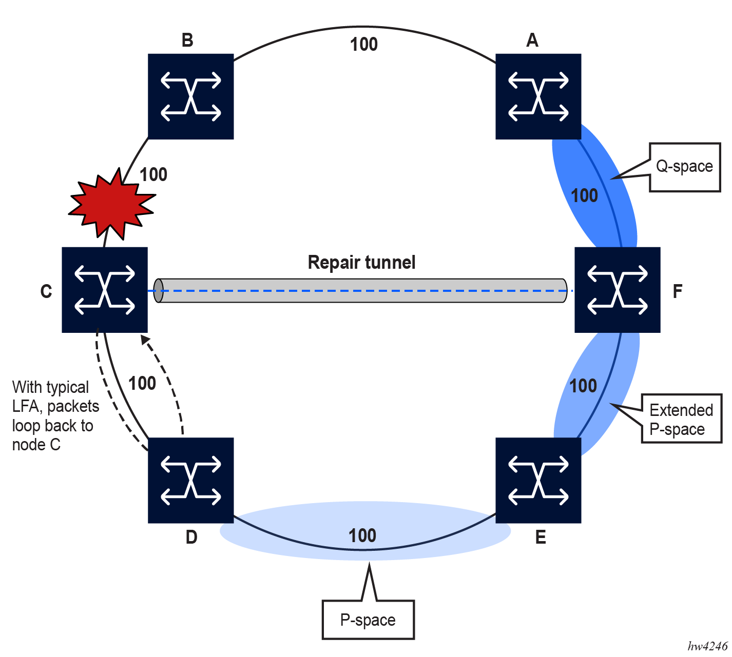
If the typical LFA SPF in node C computes the per-prefix LFA next hop, prefixes that use link C-B as the primary next hop have no LFA next hop because of the ring topology. For example, if node C uses node link C-D as a backup next hop, node D would loop the packets back to node C.
However, with remote LFA enabled, node C runs the following PQ algorithm, per RFC 7490.
-
Compute the extended P space of node C with respect to link C-B.
The extended P space is the set of nodes that are reachable from node C without any path transiting the protected link (link C-B). This computation yields nodes D, E, and F.
The determination of the extended P space by node C uses the same computation as the regular LFA by running SPF on behalf of each of the neighbors of C.
Note: Per RFC 7490, the P space of node C excludes node F because node C has two ECMP paths to node F, one of which traverses link C-B. This exclusion prevents node C from attempting a repair via the failed link C-B. However, with remote LFA enabled, node F is included in the extended P space for node C. -
Compute the Q space of node B with respect to link C-B.
The Q space is the set of nodes that can reach the destination proxy (node B) without any path transiting the protected link (link C-B).
The Q space calculation is effectively a reverse SPF of node B. In general, one reverse SPF is run on behalf of each neighbor of C to protect all destinations resolving over the link to the neighbor. This yields nodes F and A.
-
Select the best alternate node.
This is the intersection of extended P and Q spaces. The best alternate node (PQ node) is node F in the preceding figure. From node F onwards, traffic follows the IGP shortest path.
If many PQ nodes exist, the lowest IGP cost from node C is used to narrow down the selection, and if more than one PQ node remains, the node with the lowest router ID is selected.
Label stack encoding
The details of the label stack encoding when the packet is forwarded over the remote LFA next hop are shown in the following figure.
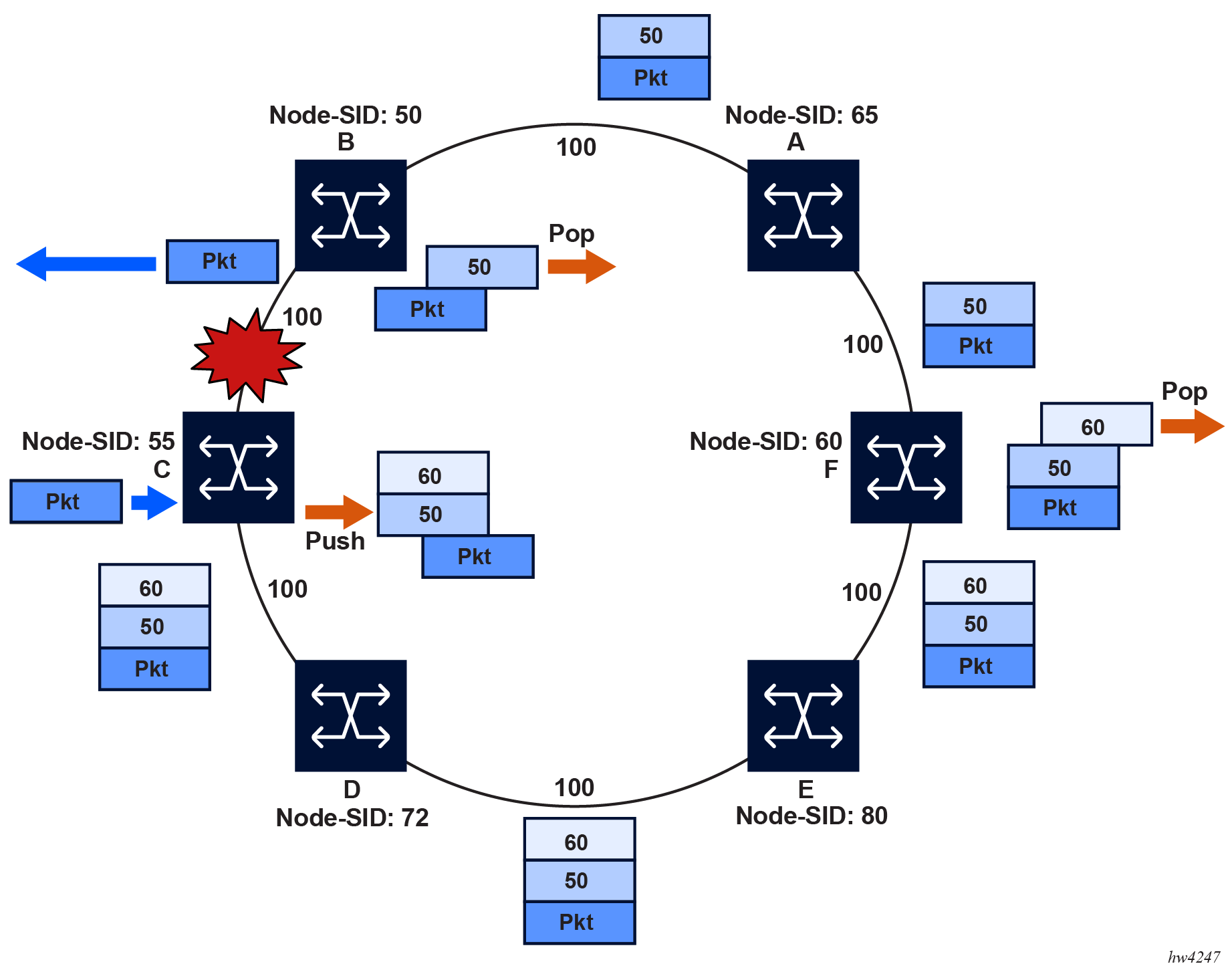
The label corresponding to the node SID of the PQ node is pushed on top of the original label of the SID of the resolved destination prefix. If node C has resolved multiple node SIDs corresponding to different prefixes of the selected PQ node, it pushes the lowest node SID label on the packet when forwarded over the remote LFA backup next hop.
If the PQ node is also the advertising router for the resolved prefix, the label stack is compressed. In IS-IS, the label stack is always reduced to a single label, which is the label of the resolved prefix owned by the PQ node.
Remote LFA rules and limitations
The following rules and limitations apply to the remote LFA implementation.
-
If you exclude a network IP interface from being used as an LFA next-hop using the loopfree-alternate exclude command under the IS-IS context of the interface, the interface is also excluded from being used as the outgoing interface for a remote LFA tunnel next hop.
-
As with the regular LFA algorithm, the remote LFA algorithm computes a backup next hop to the ABR advertising an inter-area prefix and not to the destination prefix.
Remote LFA node-protect operation
SR Linux supports the node-protect extensions to the remote LFA algorithm, as described in RFC 8102. When node protection is enabled, the router prefers a node-protect over a link-protect repair tunnel in the RLFA SPF computations. This feature protects against the failure of a downstream node. The node-protect extensions are additions to the original link-protect LFA SPF algorithm.
Remote LFA follows a similar algorithm as TI-LFA but does not limit the scope of the calculation of the extended P-Space and of the Q-Space to the post-convergence paths.
Remote LFA adds an extra forward SPF on behalf of the PQ node to ensure that, for each destination, the selected PQ-node does not use a path via the protected node.
The following figure shows an example of remote LFA for node protection.
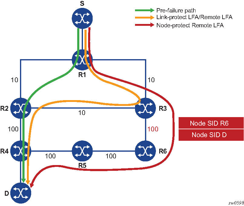
Using the topology in the preceding figure, the node-protect remote LFA algorithm computation is performed in the following sequence.
-
Compute extended P-Space of R1 with respect to protected node R2.
This is the set of nodes Yi which are reachable from R1 neighbors, other than protected node R2, without any path transiting the protected node R2.
R1 computes an LFA SPF rooted at each of its neighbors, for example, R3, using the following equation:
Distance_opt(R3, Yi) < Distance_opt(R3, R2) + Distance_opt(R2, Yi)Where Distance_opt(A,B) is the shortest distance between A and B.
Nodes R3, R5, and R6 satisfy this inequality.
-
Compute Q-space of R1 with respect to protected link R1-R2.
This is the set of nodes Zi from which node R2 can be reached without any path transiting the protected link R1-R2, using the following equation.
Distance_opt(Zi, R2) < Distance_opt(Zi, R1) + Distance_opt(R1, R2)The reverse SPF for the Q-space calculation is the same as in the remote LFA link-protect algorithm and uses the protected node R2 as the proxy for all destination prefixes.
This step yields nodes R3, R4, R5, and R6.
-
For each PQ node found, run a forward SPF to each destination D.
This step is required to select only the subset of PQ-nodes that do not traverse protected node R2.
Distance_opt(PQi, D) < Distance_opt(PQi, R2) + Distance_opt(R2, D)Of the candidates PQ nodes R3, R5, and R6, only PQ-nodes R5 and R6 satisfy this inequality. PQ-node R6 is closer in terms of IGP cost to computing router R1 and is therefore selected.
This step of the algorithm is applied to the subset of candidate PQ-nodes out of steps 1 and 2 and to which the max-pq-cost parameter was already applied. This subset is further reduced in this step by retaining the candidate PQ-nodes that provide the highest coverage among all protected nodes in the topology, and the number of which does not exceed the value of the max-pq-nodes parameter.
-
Select a PQ-Node.
If multiple PQ nodes satisfy the criteria in all the above steps, then R1 further selects the PQ node as follows.
-
R1 selects the lowest IGP cost from R1.
-
If more than one PQ-nodes remains, R1 selects the PQ-node reachable via the neighbor with the lowest system ID.
-
If more than one PQ-node remains, R1 selects the PQ node with the lowest system ID.
-
- Program the remote LFA backup path.For each destination prefix D, R1 programs the remote LFA backup path as follows.
-
For prefixes of R4 or downstream of R4, R1 programs a node-protect remote LFA repair tunnel to the PQ-node R6 by pushing the SID of node R6 on top of the SID for destination D and programming a next hop of R3.
-
For prefixes owned by node R2, R1 runs the link-protect remote LFA algorithm and programs a simple link-protect repair tunnel that consists of a backup next hop of R3 and pushes no additional label on top of the SID for the destination prefix.
-
Prefixes owned by nodes R3, R6, and R5 are not impacted by the failure of R2 because their primary next hop is R3.
-
Configuring Remote LFA
To enable remote LFA in IS-IS, use the remote-lfa option.
In topologies where many eligible P or Q nodes can exist, you can specify the max-pq-cost to limit the P and Q node searches and reduce the number of SPF calculations. This option specifies the maximum IGP cost allowed from the point of local repair (PLR) to a candidate node for the PLR to consider the candidate as an eligible PQ node.
Configure remote LFA
--{ +* candidate shared default }--[  ]--
# info network-instance default protocols isis instance sr-isis-test loopfree-alternate
    network-instance default {
        protocols {
            isis {
                instance sr-isis-test {
                    loopfree-alternate {
                        remote-lfa {
                            admin-state enable
                            max-pq-cost 100
                        }
                    }
                }
            }
        }
    }
Excluding interfaces from LFA
To exclude a network IP interface from being used as the outgoing interface for a remote LFA tunnel next hop, use the loopfree-alternate-exclude true command.
Exclude interfaces from LFA
--{ +* candidate shared default }--[  ]--
# info network-instance default protocols isis instance sr-isis-test interface ethernet-1/1.1
    network-instance default {
        protocols {
            isis {
                instance sr-isis-test {
                    interface ethernet-1/1.1 {
                        loopfree-alternate-exclude true
                    }
                }
            }
        }
    }
Excluding an IS-IS instance from LFA
To exclude an entire IS-IS instance from the LFA calculations, use the loopfree-alternate-exclude true command.
Exclude an IS-IS instance from LFA
--{ candidate shared default }--[  ]--
# info network-instance default protocols isis instance 1 level 1 loopfree-alternate-exclude
    network-instance default {
        protocols {
            isis {
                instance 1 {
                    level 1 {
                        loopfree-alternate-exclude true
                    }
                }
            }
        }
    }
Configuring node protection in RLFA
To configure the RLFA node protection feature, use the node-protect admin-state enable command.
Configure RLFA node protection
--{ +* candidate shared default }--[  ]--
# info network-instance default protocols isis instance sr-isis-test loopfree-alternate remote-lfa
    network-instance default {
        protocols {
            isis {
                instance sr-isis-test {
                    loopfree-alternate {
                        remote-lfa {
                            admin-state enable
                            max-pq-cost 100
                            node-protect {
                                admin-state enable
                                max-pq-nodes 8
                            }
                        }
                    }
                }
            }
        }
    }
Topology-independent LFA
Topology-independent LFA (TI-LFA) improves the protection coverage of a network topology by computing and automatically instantiating a repair tunnel to a Q-node that is not in the shortest path from the computing node. The repair tunnel uses the shortest path to the P-node and a source-routed path from the P-node to the Q-node.
In addition, the TI-LFA algorithm selects the backup path that matches the post-convergence path. This improves capacity planning in the network because traffic always flows on the same path when transitioning to the FRR next hop and then on to the new primary next hop.
At a high level, the TI-LFA link protection algorithm searches for the closest Q-node to the computing node and then selects the closest P-node to this Q-node, up to a maximum number of labels. This is performed on each of the post-convergence paths to each destination node or prefix D.
When the TI-LFA feature is enabled in IS-IS, it provides a TI-LFA link-protect backup path in IS-IS MT=0 for an SR IS-IS IPv4 or SR IS-IS IPv6 tunnel (node SID and adjacency SID) and for an IPv4 TE-Policy SR-MPLS uncolored tunnel resolving to SR-ISIS.
TI-LFA algorithm
For each destination node or prefix D, the TI-LFA link protection algorithm searches on each of the post-convergence paths for the closest Q-node to the computing node and then selects the closest P-node to this Q-node, up to a maximum configurable number of 3 labels.
The following figure shows a topology where router R3 computes a TI-LFA next hop for protecting link R3-R4.
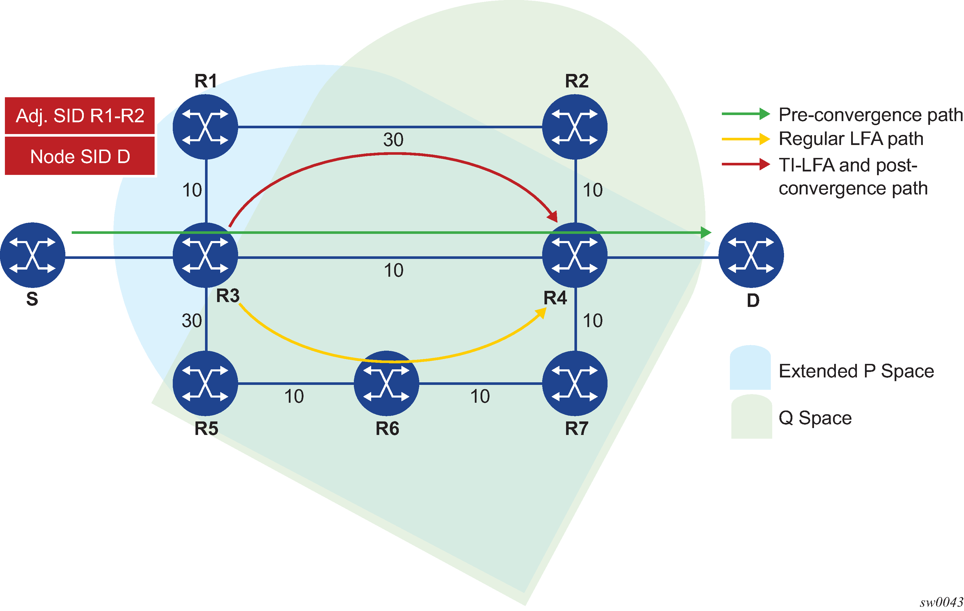
In this topology, router R3 computes the link-protected TI-LFA backup path in the following order.
-
Compute the post-convergence SPF on the topology without the protected link.
R3 finds a single post-convergence path to destination D via R1.
-
Compute the extended P-Space of R3 with respect to protected link R3-R4 on the post-convergence paths.
This is the set of nodes Yi in the post-convergence paths that are reachable from R3 neighbors without any path transiting the protected link R3-R4.
R3 computes an LFA SPF rooted at each of its neighbors within the post-convergence paths, that is, R1, using the following equation:
Distance_opt(R1, Yi) < Distance_opt(R1, R3) + Distance_opt(R3, Yi)Where Distance_opt(A,B) is the shortest distance between A and B. The extended P-space calculation yields only node R1.
-
Compute the Q-space of R3 with respect to protected link R3-R4 in the post-convergence paths.
This is the set of nodes Zi in the post-convergence paths from which the neighbor node R4 of the protected link, acting as a proxy for all destinations D, can be reached without any path transiting the protected link R3-R4.
Distance_opt(Zi, R4) < Distance_opt(Zi, R3) + Distance_opt(R3, R4)The Q-space calculation yields nodes R2 and R4.
This is the same computation of the Q-space performed by the remote LFA algorithm, except that the TI-LFA Q-space computation is performed only on the post-convergence paths.
-
For each post-convergence path, search for the closest Q-node and select the closest P-node to this Q-node, up to the configurable maximum number of labels.
The preceding topology diagram shows a single post-convergence path and a single P-node (R1). It also shows that R2 is the closest of the two found Q-nodes to the P-Node.
R3 installs the repair tunnel to the P-Q set and includes the node SID of R1 and the adjacency SID of the adjacency over link R1-R2 in the label stack. Because the P-node R1 is a neighbor of the computing node R3, the node SID of R1 is not needed and the label stack of the repair tunnel is compressed to the adjacency SID over link R1-R2 as shown.
When a P-Q set is found on multiple ECMP post-convergence paths, the following selection rules are applied, in ascending order, to select a set from a single path:
-
the lowest number of labels
-
the next hop to the neighbor router with the lowest System ID
-
the next hop corresponding to the Q node with the lowest System ID
If multiple links with adjacency SIDs exist between the selected P-node and the selected Q-node, the following rules are used for link selection:
-
the adjacency SID with the lowest metric
-
the adjacency SID with the lowest SID value if the lowest metric is the same
-
TI-LFA feature interaction and limitations
Because the post-convergence SPF does not use paths transiting on a node in IS-IS overload, the TI-LFA backup path automatically does not transit on such a node.
LFA protection option applicability
Depending on the LFA options that are configured, the LFA SPF in the IGP instance runs the following algorithms in order.
- Compute a regular LFA for each node and prefix.
In this step, a computed backup next hop satisfies any applied LFA policy. This backup next hop protects that specific prefix or node in the context of LDP FRR, SR FRR, and TE-Policy SR-MPLS FRR.
- If TI-LFA is enabled, run the TI-LFA algorithm for all prefixes and nodes.
If the LDP loopfree-alternate option is enabled, a prefix or node for which a TI-LFA backup next hop is found overrides the result from step 1 in the context of LDP FRR in SR FRR and in TE-Policy SR-MPLS FRR.
With SR FRR, the TI-LFA next hop protects the node-SID of that prefix and any adjacency SID terminating on the same node-SID.
The prefix or node continues to use the backup next hop found in the context of LDP FRR.
- If RLFA is enabled, run remote LFA only for the next hop of prefixes and
nodes that remain unprotected after steps 1 and 2.
A prefix or node for which a remote LFA backup next hop is found uses it in the context of LDP FRR in SR FRR and in TE-Policy SR-MPLS FRR.
- adjacency SID of an alternate ECMP next hop
- TI-LFA backup next hop
- remote LFA backup next hop
TI-LFA node-protect operation
SR Linux supports the node-protect extensions to the TI-LFA algorithm as described in draft-ietf-rtgwg-segment-routing-ti-lfa-01. When node protection is enabled, the router prefers a node-protect over a link-protect repair tunnel in the TI-LFA SPF computations. This feature protects against the failure of a downstream node. The node-protect extensions are additions to the original link-protect LFA SPF algorithm.
The following figure shows a simple topology to illustrate the node-protect operation for TI-LFA. It uses the same topology as shown in Remote LFA node-protect operation, but the metric for link R3-R6 is modified to 1000.
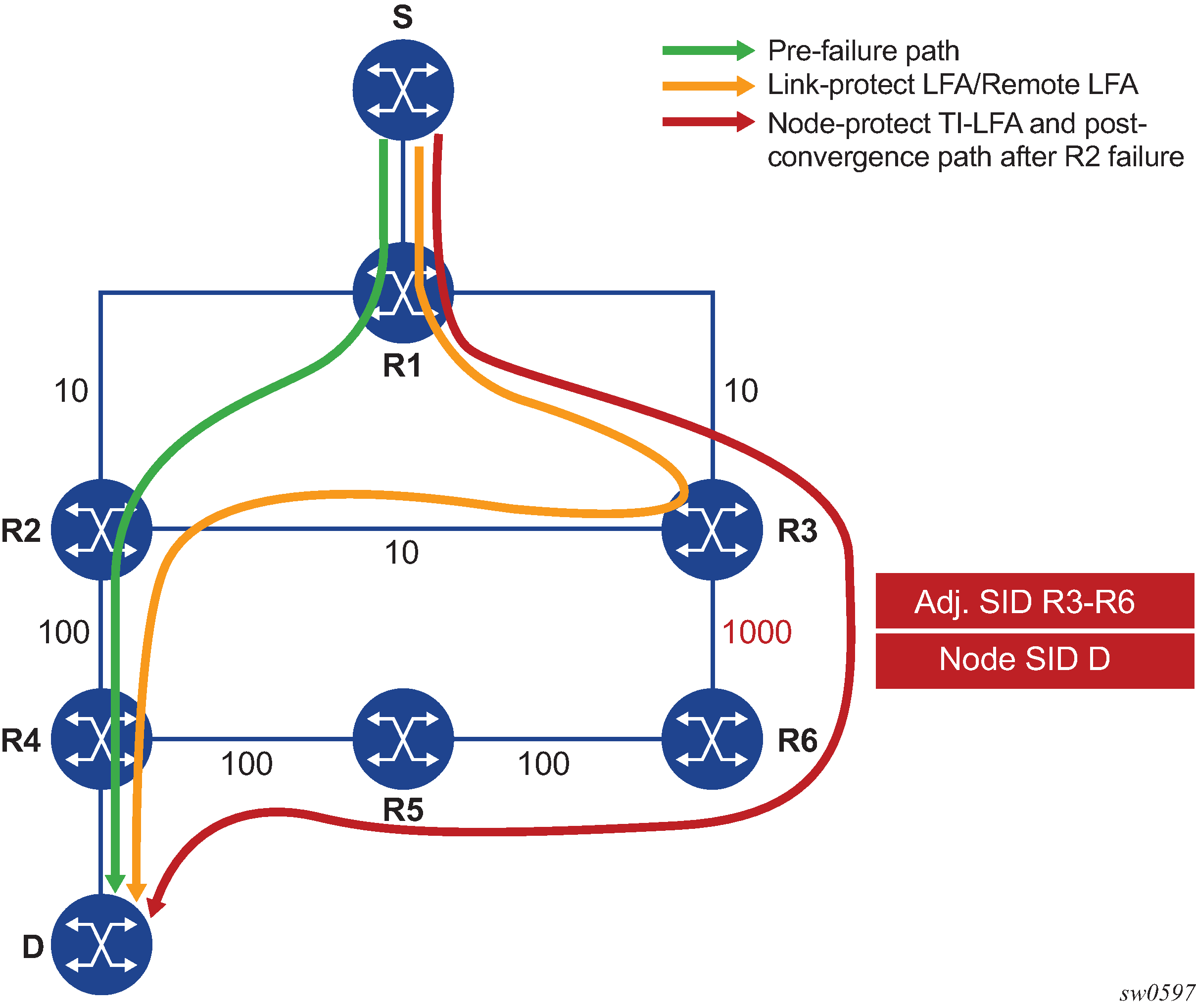
The main change as a result of the node-protect extension is that the algorithm protects a node instead of a link.
Using the topology in the preceding figure, the node protection computation is performed in the following sequence.
-
Compute the post-convergence SPF on the topology without the protected node.
In the preceding figure, R1 computes TI-LFA on the topology without the protected node R2 and finds a single post-convergence path to destination D via R3 and R6.
Prefixes owned by all other nodes in the topology have a post-convergence path via R3 and R6 except for prefixes owned by node R2. The latter uses the link R3-R2 and they can only benefit from link protection.
-
Compute the extended P-Space of R1 with respect to protected node R2 on the post-convergence paths.
This is the set of nodes Yi in the post-convergence paths that are reachable from R1 neighbors, other than protected node R2, without any path transiting the protected node R2.
R1 computes an LFA SPF rooted at each of its neighbors within the post-convergence paths. For example, R1 uses using the following calculation to compute the LFA SPF for R3:
Distance_opt(R3, Yi) < Distance_opt(R3, R2) + Distance_opt(R2, Yi)Where Distance_opt(A,B) is the shortest distance between A and B.
The extended P-space calculation yields node R3 only.
-
Compute the Q-space of R1 with respect to protected link R1-R2 on the post-convergence paths.
This is the set of nodes Zi in the post-convergence paths from which node R2 can be reached without any path transiting the protected link R1-R2, using the following equation:
Distance_opt(Zi, R2) < Distance_opt(Zi, R1) + Distance_opt(R1, R2)The reverse SPF for the Q-space calculation is the same as in the link-protect algorithm and uses the protected node R2 as the proxy for all destination prefixes. To compute the Q space with respect to the protected node R2 instead of link R1-R2, a reverse SPF would have to be performed for each destination D which is very costly and not scalable. However, this means the path from the Q-node to the destination D or the path from the P-node to the Q-node is not guaranteed to avoid the protected node R2. The intersection of the Q-space with post-convergence path is modified in the next step to mitigate this risk.
This step yields nodes R3, R4, R5, and R6.
-
For each post-convergence path, search for the closest Q-node to destination D and select the closest P-node to this Q-node, up to the configurable maximum number of labels.
This step yields the following P-Q sets, depending on the value of the ti-lfa max-sr-policy-lfa-labels parameter:
-
max-sr-policy-lfa-labels=0
R3 is the closest Q-node to the destination D and R3 is the only P-node. This case results in link protection via PQ-node R3.
-
max-sr-policy-lfa-labels=1
R6 is the closest Q-node to the destination D and R3 is the only P-node. The repair tunnel for this case uses the SID of the adjacency over link R3-R6 and is shown in the topology diagram.
-
max-sr-policy-lfa-labels=2 (default)
R5 is the closest Q-node to the destination D and R3 is the only P-node. The repair tunnel for this case uses the SIDs of the adjacencies over links R3-R6 and R6-R5.
-
max-sr-policy-lfa-labels=3
R4 is the closest Q-node to the destination D and R3 is the only P-node. The repair tunnel for this case uses the SIDs of the adjacencies over links R3-R6, R6-R5, and R5-R4.
This step of the algorithm is modified from link protection, which prefers Q-nodes that are the closest to the computing router R1. This is to minimize the probability that the path from the Q-node to the destination D, or the path from the P-node to the Q-node, goes via the protected node R2 as described in step 2. However, there is still a probability that the found P-Q set achieves link protection only.
-
-
Select the P-Q Set.
If a candidate P-Q set is found on each of the multiple ECMP post-convergence paths in step 4, the following selection rules are applied in ascending order to select a single set:
-
the lowest number of labels
-
the lowest next-hop router ID
-
the lowest subinterface index if the same as the next-hop router ID
If multiple parallel links with adjacency SID exist between the P- and Q-nodes of the selected P-Q set, the following rules are used to select one of them:
-
the adjacency SID with lowest metric
-
the adjacency SID with the lowest SID value, if the same as the lowest metric
-
- Program the TI-LFA repair tunnel.
For each destination prefix D, R1 programs the TI-LFA repair tunnel (max-sr-policy-lfa-labels=1):
-
For prefixes other than those owned by node R2, R1 programs a node-protect repair tunnel to the P-Q pair R3-R6 by pushing the SID of adjacency R3-R6 on top of the SID for destination D and programming a next hop of R3.
- For prefixes owned by node R2, R1 runs the link-protect TI-LFA algorithm and programs a simple link-protect repair tunnel, which consists of a backup next hop of R3 and pushes no additional label on top of the SID for the destination prefix.
-
TI-LFA and remote LFA node protection feature interaction and limitations
The order of activation of the various LFA types on a per prefix basis is as follows: TI-LFA, followed by base LFA, followed by remote LFA. See LFA protection option applicability for more information about the order of activation.
Node protection is enabled for TI-LFA and remote LFA separately. The base LFA prefers node protection over link protection.
The order of activation of the LFA types supersedes the protection type (node versus link). Consequently, a prefix can be programmed with a link-protect backup next hop by the more preferred LFA type. For example, a prefix is programmed with the only link-protect backup next hop found by the base LFA when a node-protect remote LFA next hop exists.
Configuring TI-LFA
To enable TI-LFA in an IS-IS instance, use the loopfree-alternate ti-lfa command.
Enable TI-LFA on an ISIS instance
--{ candidate shared default }--[  ]--
# info network-instance default protocols isis instance sr-isis-test loopfree-alternate ti-lfa
    network-instance default {
        protocols {
            isis {
                instance sr-isis-test {
                    loopfree-alternate {
                        ti-lfa {
                            admin-state enable
                            max-sr-policy-lfa-labels 1
                        }
                    }
                }
            }
        }
    }