
DCO transceiver loopback
In SR Linux, configure transceiver loopbacks on a terminal-device logical channel. This is separate from the loopback-mode configured on an Ethernet interface or VLAN subinterface.
Use the following command to configure the transceiver loopback mode.
terminal-device logical-channels channel loopback-modeThe loopback values use the same names as port loopback. They activate a loopback inside the DCO for that logical channel. See Physical port and VLAN loopback for port-level and VLAN loopback-mode configuration.
SR Linux supports the following options for the DCO transceiver loopback mode:
- facility
The signal received on a transceiver interface is returned out of that same interface as follows:
- applied to an OTN logical channel: media side input loopback – transceiver optical input signal returns to the optical output
- applied to an Ethernet logical channel: host side input loopback – signal received from the transceiver host interface returns to the host-facing output
- terminalThe signal transmitted out of a transceiver interface is turned around into the receive path of the interface as follows:
- applied to an OTN logical channel: media side output loopback – signal destined for the transceiver optical output loops back into the optical receive path
- applied to an Ethernet logical channel: host side output loopback – signal destined for the transceiver host interface loops back into the host receive path
- none
This option removes the loopback.
See Configuring a DCO transceiver loopback for a configuration example.
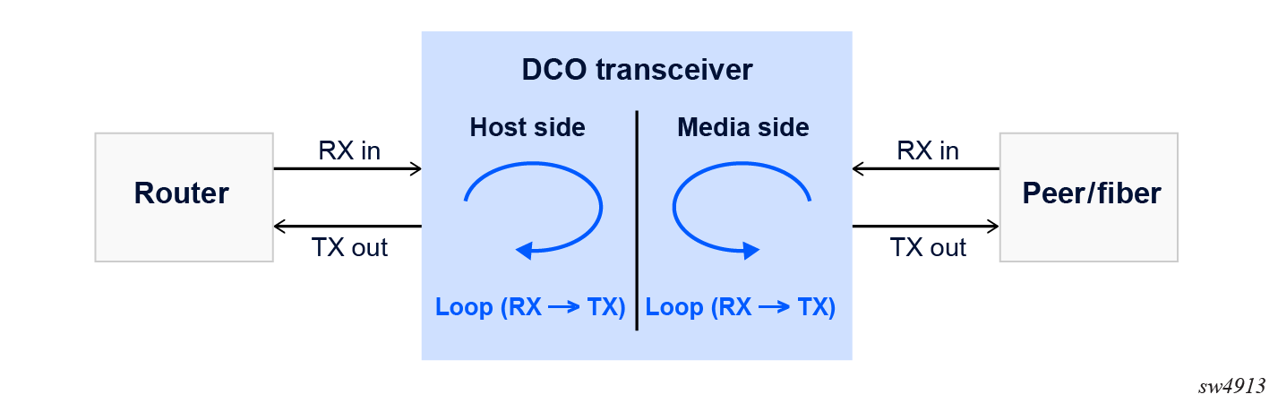
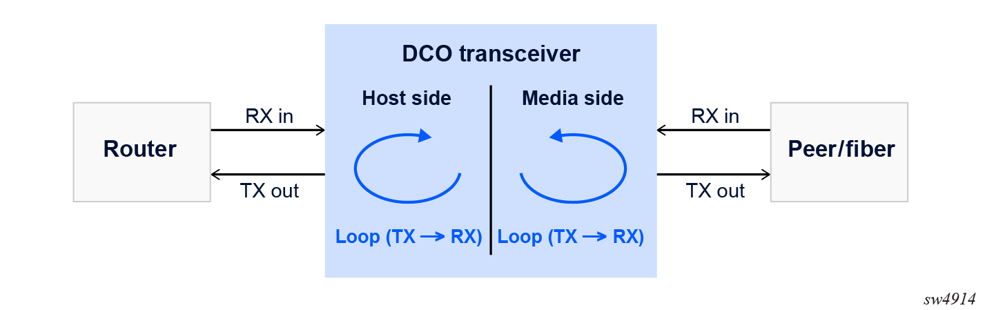
As noted, the facility and terminal loopback modes on the DCO terminal-device logical channel apply on the host side or on the media side per logical channel (one channel at a time). Which side of the transceiver is affected depends on the logical channel type:
- Inside the transceiver, on Ethernet client logical channels, the loopback modes reference the host side of the module.
- On the OTN logical channel associated with the transceiver optical-channel, the loopback modes reference the media (line) side.
The following figures show facility and terminal loopbacks on the host side of the DCO.
Configuring a DCO transceiver loopback
You can configure a loopback on the terminal-device logical channel that is tied to your DCO, and then commit the change.
Configure the loopback mode to facility or terminal, or set it to none to remove loopback. See DCO transceiver loopback for more information.
The following example sets the loopback mode to facility on OTN logical channel 1.
Facility loopback on an OTN logical channel
--{ candidate shared default }--[  ]--
# info with-context terminal-device logical-channels channel 1
    terminal-device {
        logical-channels {
            channel 1 {
                loopback-mode facility
                logical-channel-type protocol-otn
            }
        }
    }