
BGP Signaled Segment Routing Policy
This chapter describes BGP Signaled Segment Routing Policy.
Topics in this chapter include:
Applicability
The CLI in the latest update of this chapter is based on SR Linux Release 26.3.1.
Overview
Segment Routing (SR) allows a head-end node to steer a packet flow along a source-routed path. SR TE policy is a generic framework that describes the procedures and processes that a head-end node carries out when instantiating such a path. The SR TE policy consists of an ordered list of segments on a node, sufficient to implement a traffic-engineered path. The segments can have any type of Segment Identifier (SID), including Adjacency-SIDs, Node-SIDs, Anycast-SIDs, or Binding SIDs. The head-end can then steer traffic, using the SR TE policy as appropriate.
An SR TE policy can define one or multiple candidate paths. When explicit candidate paths are used, each path contains one or more segment lists, where each segment list contains the ordered set of segments (identified by their unique SID) required to provide the source-routed path from head-end to destination. When a candidate path contains multiple segment lists, each is assigned a weight for the purpose of weighted load-balancing. Candidate paths can be instantiated using a variety of ways, including Path Computation Element Protocol (PCEP), BGP, or local configuration. This chapter describes the use of BGP to advertise SR TE policy candidate paths.
SR TE policy overview
An SR TE policy is identified through the tuple {head-end, color, endpoint}.
-
The head-end is the node where the SR TE policy is instantiated, and the node that is responsible for steering traffic, using the SR TE policy with the relevant SID stack. From the perspective of the head-end, the SR TE policy can be identified using the {color, endpoint} tuple.
-
The color is a fundamental part of the SR TE policy and forms part of the Network Layer Reachability Information (NLRI). The color is a 32-bit numerical value that a head-end uses to associate the SR TE policy with a characteristic, such as low-latency or high-throughput.
-
The endpoint is the destination in the SR TE policy specified as an IPv4 or IPv6 address, although "wildcard" destinations can be used and are described later in this chapter.
Color is also a 32-bit transitive extended community originally defined in draft-ietf-idr-tunnel-encaps that can be attached to a BGP update message, to associate it with a corresponding SR TE policy. For example, if head-end H learns a BGP route R with {next-hop N, color extended community C, and VPN label V} and head-end H has a valid SR TE policy P to {endpoint N, color C}, it can associate BGP route R with the SR TE policy P. When H receives packets with a destination matching BGP route R, it forwards them using the instructions contained within SR TE policy P.
SR TE policy NLRI
The BGP address family srte-policy-ipv4 or srte-policy-ipv6 (SAFI 73) is defined to advertise a candidate path for an SR TE policy in BGP and is carried in an update message using BGP multiprotocol extensions. The AFI must be IPv4 (AFI=1) or IPv6 (AFI=2). An SR TE policy candidate path may be advertised from a centralized controller, or it may be advertised by a router; for example, an egress router advertising paths to itself. SR TE policy NLRI shows the structure of the SR TE policy NLRI.
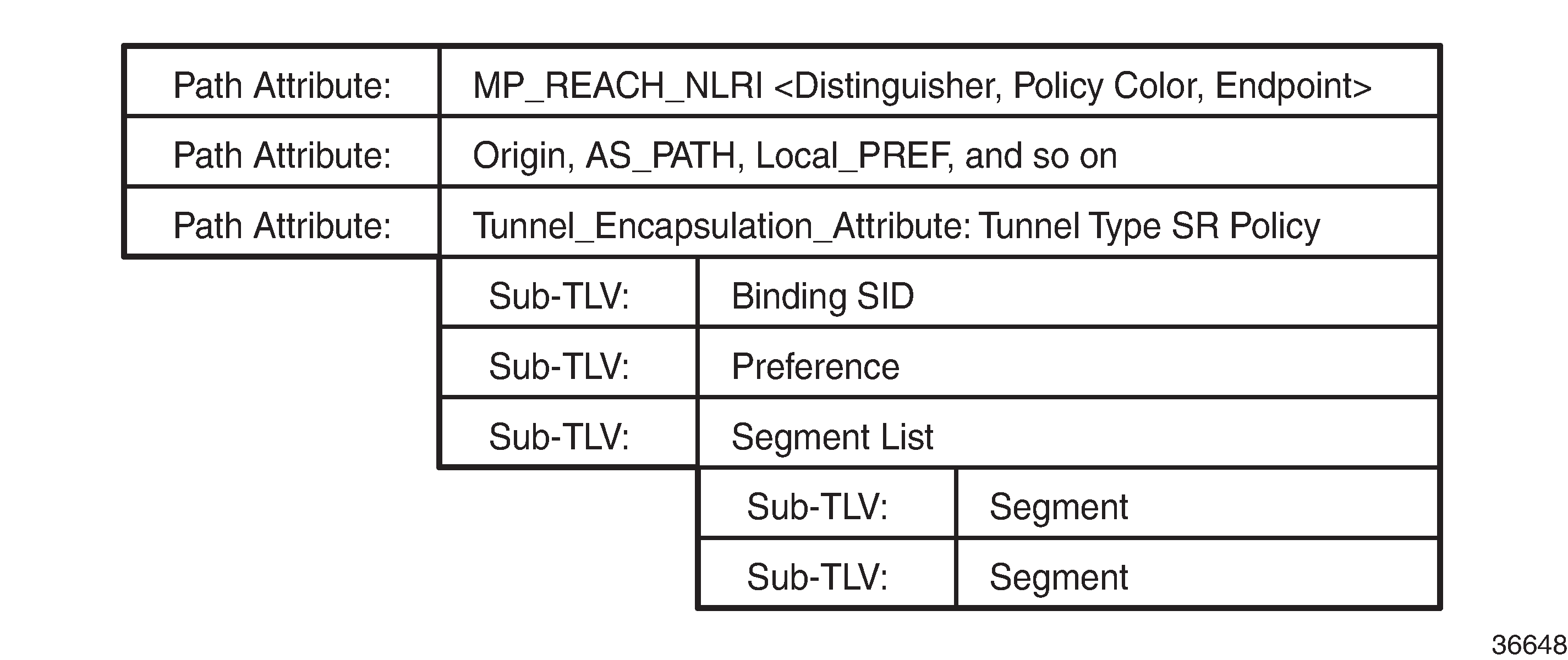
The SR TE policy NLRI is used to identify an SR TE policy candidate path and, because it uses MP-BGP, it is carried in an MP_REACH/UNREACH_NLRI path attribute. The NLRI contains the color and endpoint values described previously, and a discriminator. The discriminator is an integer value in the range 1 to 4294967295 that serves to make the SR TE policy unique from an NLRI perspective. The SR TE policy NLRI uses standard BGP propagation and best-path selection; a unique discriminator ensures that best-path selection does not unnecessarily suppress SR TE policy advertisements.
Multiple candidate paths can exist for an SR TE policy, although only one path can be selected as the best path of the SR TE policy and become the active path. If several candidate paths of the same SR TE policy (endpoint, color) are advertised via BGP SR TE policy to the same head-end, unique discriminators for each NLRI are recommended.
The other parameters of the SR TE policy candidate path are carried as sub-TLVs of the Tunnel Encapsulation Attribute (draft-ietf-idr-tunnel-encaps) using a tunnel encapsulation type known as SR TE policy (srte-policy), and are described following.
Binding SID
The SR architecture defines the use of a Binding SID (BSID). A BSID is bound to an SR TE policy, and packets arriving at a node with an active label equal to the BSID are steered using that SR TE policy. This action may mean swapping the incoming active label with one or more outgoing labels representing the SR TE policy path.
When used in this manner, the Binding SID serves as an anchor point, sometimes referred to as a BSID anchor, that allows one domain to be isolated from another domain. This is shown in Binding SID (BSID) anchor, where ABR-3 is acting as a BSID anchor between the aggregation domain and the core domain. ABR-3 has an SR TE policy to PE-7 with the path P-4-P-5-P-6 and with a BSID of 1000. The PE-1 resulting SR TE policy to PE-7 consists of the path {Node-SID ABR-3, 1000, Node-SID PE-7} and a BSID of 500. When a packet is forwarded by the SR TE policy on PE-1 and arrives at ABR-3, it pops the Node-SID ABR-3 label, and swaps label 1000 for the label stack {P-4, P-5, P-6} of the SR TE policy on ABR-3.
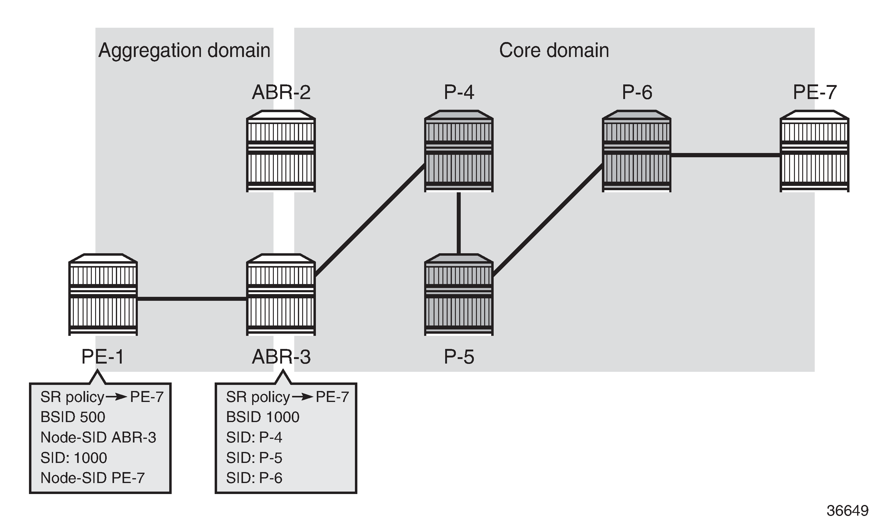
The BSID serves as an anchor point, which allows one domain to be isolated from the churn of another domain. If something changes in the path P-4-P-5-P-6, ABR-3 can repair the path locally without needing to change the BSID value known at PE-1. PE-1 is therefore protected from the churn in the core domain. The BSID also serves to reduce the number of segments/labels that the head-end needs to impose an end-to-end traffic-engineered path.
Segment list
A segment list sub-TLV encodes a single path toward the endpoint. Multiple segment list sub-TLVs may be included in each SR TE policy. Each segment list sub-TLV may contain multiple segment sub-TLVs and may carry a weight sub-TLV. Each segment sub-TLV describes a single segment in a segment list, and multiple segments may be concatenated to constitute an end-to-end path of the SR TE policy.
There are several types of the segment sub-TLV, allowing for the segment to be expressed as a variant of IPv4/IPv6 node address or local/remote address, and with a SID in the form of an MPLS label or IPv6 address. This chapter focuses only on the Type A encoding, which is represented as a SID in the form of an MPLS label. The SID contained within each segment sub-TLV can be any type of SID, including Node-SID, Adjacency-SID, Anycast-SID, or Binding SID.
The optional weight sub-TLV is used to implement (weighted) load-balancing in the presence of multiple segment lists. By default, SR Linux assigns a weight value of 1 to each segment list.
Preference
The preference sub-TLV is used to indicate the preference of a candidate path in relation to other candidate paths. Multiple candidate paths can exist in an SR TE policy, but only one candidate path can be selected as the best and active path. When multiple candidate paths exist that are considered valid, the candidate path with the highest preference is selected. The default value of the preference is 100. If multiple paths have the same preference, the protocol origin (PCEP, BGP, local configuration) may be considered, followed by the lower value of originator, followed by the higher value of discriminator.
SR TE policy candidate path
The symbolic name associated with an SR TE policy candidate path
Example topology
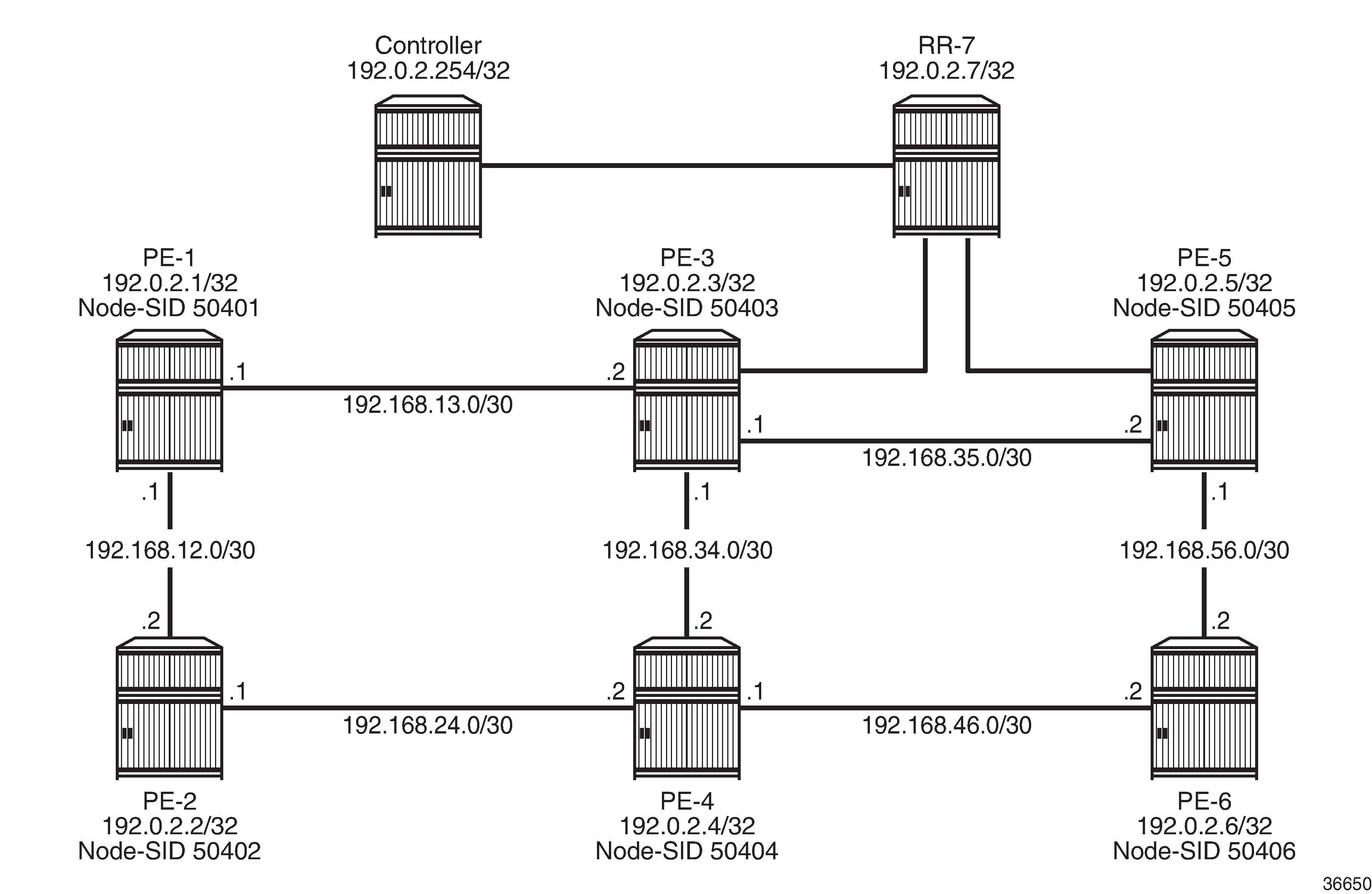
The topology in Example topology shows the use of BGP SR TE policy within this chapter. All PE routers within the example topology and the Route Reflector (RR-7) form part of Autonomous System 64496 and belong to the same IS-IS Level-2 area. All IGP link metrics are 100 and are symmetric. SR is enabled within the domain, and the associated Node-SIDs are shown in Example topology (Adj-SIDs are not shown for the purpose of clarity). The SRGB in use is {50000-54999}. All PE routers are clients of the Route Reflector for multiple address families including srte-policy-ipv4.
The example topology also has an additional router simulating a controller, which uses static routing for IP connectivity. This is the point from which SR TE policies are advertised into BGP, although as previously described, SR TE policies can be advertised into BGP by a controller or a router. The controller peers in the srte-policy-ipv4 address family with the Route Reflector, which in turn reflects those routes to its clients.
Configuration
An SR TE policy can be statically (CLI) configured locally on a head-end or dynamically learned by a head-end through a BGP SR TE policy route. For SR Linux to obtain an SR TE policy route, that route needs to be configured locally as a static SR TE policy. This chapter provides an example of the instantiation of an SR TE policy using static configuration on the head-end, but thereafter focuses on the instantiation of SR TE policies learned by it through BGP SR TE policy. The same static SR TE policy configuration is used regardless of whether it is for advertising that SR TE policy into BGP to the head-end, or applying it at that local head-end to forward traffic.
Segment Routing Local Block
A BSID may be either a local SID or a global SID. In general, and for the use-cases in this chapter, BSIDs are local SIDs, so a BSID needs to be within the range of a locally-configured Segment Routing Local Block (SRLB). SRLBs are reserved label blocks used for specific local purposes, such as SR TE policy BSIDs, Adjacency Set SIDs, and static Adjacency SIDs. A dedicated SRLB is required per application and has only local significance, so the same values can be used on all SR routers in the domain. Ranges for each SRLB are taken from the dynamic label range. The following configuration allocates labels 100000 to109999 to the SRLB SRLB-BSID:
# on all nodes:
enter candidate
    system {
        mpls {
            label-ranges {
                static SRLB-BSID {
                    shared false
                    start-label 100000
                    end-label 109999
                }
After the SRLB is defined, it is dedicated to the specific application, which in this case is SR TE policies, as follows:
# on all nodes:
enter candidate
    network-instance default {
        traffic-engineering-policies {
            binding-sid {
                static-label-block SRLB-BSID
            }
The preceding configuration is applied to all SR routers in the domain.
Static SR TE policy
As previously described, SR TE policies can be statically (CLI) configured locally on a head-end or dynamically learned by a head-end through a BGP SR TE policy route. In this section, the necessary steps are shown for the instantiation of an SR TE policy using static configuration locally on PE-1 as the head-end.
The following output shows the configuration of a static SR TE policy at PE-1 (192.0.2.1) with an endpoint of PE-5 (192.0.2.5).
# on PE-1:
enter candidate
    network-instance default {
        traffic-engineering-policies {
            explicit-paths {
                path p-PE-1-PE-5-c600 {
                    hop 1 {
                        mpls-label 50402    # node-SID PE-2
                    }
                    hop 2 {
                        mpls-label 150024   # adj-SID int-PE-2-PE-4
                    }
                    hop 3 {
                        mpls-label 150046   # adj-SID int-PE-4-PE-6
                    }
                    hop 4 {
                        mpls-label 50405    # node-SID PE-5
                    }
                }
            }
            policy pol-PE-1-PE-5-c600 {
                admin-state enable          # enable static SR TE policy
                policy-type sr-mpls-colored
                color 600
                endpoint 192.0.2.5
                discriminator 600001005
                head-end local
                binding-sid {
                    mpls-label 100002
                }
                segment-list 1 {
                    admin-state enable      # enable segment list
                    explicit-path p-PE-1-PE-5-c600
                }
            }
The static SR TE policy is initially created within the network-instance default traffic-engineering-policies context and has an assigned binding-sid of 100002. In this example, the SR TE policy is local to PE-1, and the BSID value is therefore within the range of the PE-1 SRLB. If this static SR TE policy were to be advertised into BGP, the advertised BSID value must be in the range of the SRLB configured on the target head-end.
Three other parameters are the color, discriminator, and endpoint that constitute the SR TE policy NLRI. The SR TE policy color is 600, and is a 4-octet value that can be configured in the range 1 to 4294967295. The discriminator is also a 4-octet value with the same range and is configured as 600001005 (representing the color plus the last octet of the head-end and endpoint addresses). As previously described, the purpose of the discriminator is to make the SR TE policy unique from an NLRI perspective, such that if multiple candidate paths of the same SR TE policy (endpoint, color) are advertised, they are not suppressed by any BGP best-path selection algorithm. The endpoint is the IPv4 or IPv6 address of the destination for the SR TE policy and is configured as the PE-5 address 192.0.2.5.
The head-end is the target node where the SR TE policy is to be instantiated. If the SR TE policy is statically configured on the head-end for forwarding of traffic locally using that SR TE policy, the value local is used, as shown in this example. If the SR TE policy is configured somewhere other than on the head-end, and advertised into BGP toward the head-end, the value of the head-end parameter is the IPv4 address of that head-end. When the SR TE policy is advertised into BGP, the head-end address is also encoded as an IPv4 address-specific Route-Target Extended Community, which allows for potential constraining of route propagation.
The final parameter is the segment list. The preceding configuration output shows the segment list consisting of an explicit path with four hops, which represent the path using the following SIDs:
-
Hop 1 SID is 50402, which is the Node-SID of PE-2
-
Hop 2 SID is 150024, representing the PE-2 Adj-SID for the link PE-2-PE-4
-
Hop 3 SID is 150046, representing the PE-4 Adj-SID for the link PE-4-PE-6
-
Hop 4 SID is 50405, which is the Node-SID of PE-5.
A more optimal SID stack is achievable in this topology, but the configured segment list shows the use of both Node- and Adj-SIDs on a loose or strict hop basis. The segment list has an optional weight parameter used for load-balancing across multiple segment lists. In this example, only a single segment list exists, so the default weight value of 1 is retained.
Finally, both the segment list and the static SR TE policy are enabled (admin-state enable).
The following output shows the operational state of the static SR TE policy. The active-candidate-path-name field shows which candidate path is the selected path in the presence of multiple candidate paths. The selected candidate path has oper-state up and a non-zero operational-segment-list-count. The segment list has oper-state up and computed-segments for the corresponding explicit-path, indicating that this is a valid segment list.
A:admin@PE-1# info from state with-context / network-instance default traffic-engineering-policies policy-database
    network-instance default {
        traffic-engineering-policies {
            policy-database {
                active-te-policies 1
                total-te-policies 1
                sr-colored {
                    policy 600 endpoint 192.0.2.5 {
                        policy-type sr-mpls-colored
                        tunnel-id 1
                        metric 200
                        created-time "2026-04-02T12:37:18.421Z (43 seconds ago)"
                        candidate-path-count 1
                        active-candidate-path-name pol-PE-1-PE-5-c600
                        oper-state up
                        oper-state-change-count 1
                        last-oper-state-change "2026-04-02T12:37:18.423Z (43 seconds ago)"
                        binding-sid {
                            mpls-label 100002
                            allocation-status true
                        }
                        candidate-path local originator-asn 0 originator-address 0.0.0.0 discriminator 600001005 {
                            candidate-path-preference 100
                            forwarding-state active
                            oper-state up
                            last-oper-state-change "2026-04-02T12:37:18.423Z (43 seconds ago)"
                            oper-state-change-count 1
                            candidate-path-name pol-PE-1-PE-5-c600
                            segment-list-count 1
                            operational-segment-list-count 1
                            protection {
                                threshold 1
                            }
                            binding-sid {
                                mpls-label 100002
                                allocation-status true
                            }
                            segment-list 1 {
                                oper-state up
                                forwarding-state active
                                last-oper-state-change "2026-04-02T12:37:18.423Z (43 seconds ago)"
                                oper-state-change-count 1
                                weight 1
                                explicit-path p-PE-1-PE-5-c600
                                metric 200
                                lsp-id 1
                                last-retry-attempt "2026-04-02T12:37:18.422Z (43 seconds ago)"
                                computed-segments {
                                    segment 1 {
                                        sid-value {
                                            mpls-label 50402
                                        }
                                    }
                                    segment 2 {
                                        sid-value {
                                            mpls-label 150024
                                        }
                                    }
                                    segment 3 {
                                        sid-value {
                                            mpls-label 150046
                                        }
                                    }
                                    segment 4 {
                                        sid-value {
                                            mpls-label 50405
                                        }
                                    }
                                }
                            }
                        }
                    }
                }
            }
If the SR TE policy is considered valid, it is populated in the tunnel table with tunnel type te-policy-sr-mpls-colored and a tunnel ID that corresponds with the tunnel-id for the SR TE policy. The entry indicates the destination and the next hop that the tunnel uses for reaching it. The tunnel to the destination is shown as follows:
A:admin@PE-1# show / network-instance default tunnel-table ipv4 192.0.2.5/32
---------------------------------------------------------------------------------------------------------------------------------------------------------
IPv4 tunnel table of network-instance "default"
---------------------------------------------------------------------------------------------------------------------------------------------------------
+--------------+--------------+--------------+--------------+--------------+--------------+--------------+--------------+--------------+--------------+
| IPv4 Prefix  | Tunnel Type  |  Tunnel ID   |     FIB      |    Metric    |  Preference  | Last Update  |    Backup    |   Next-hop   |   Next-hop   |
|              |              |              |              |              |              |              |   Nexthops   |    (Type)    |              |
+==============+==============+==============+==============+==============+==============+==============+==============+==============+==============+
| 192.0.2.5/32 | sr-isis      | 50405        | Y            | 200          | 11           | 2026-04-     |              | 192.168.13.2 | ethernet-    |
|              |              |              |              |              |              | 02T12:08:19. |              | (mpls)       | 1/3.1        |
|              |              |              |              |              |              | 944Z         |              |              |              |
| 192.0.2.5/32 | te-policy-   | 1            | Y            | 200          | 14           | 2026-04-     |              | 192.0.2.2/32 | ethernet-    |
|              | sr-mpls-     |              |              |              |              | 02T12:37:18. |              | (sr-isis)    | 1/2.1        |
|              | colored      |              |              |              |              | 424Z         |              |              |              |
+--------------+--------------+--------------+--------------+--------------+--------------+--------------+--------------+--------------+--------------+
---------------------------------------------------------------------------------------------------------------------------------------------------------
1 SR-ISIS tunnels, 1 active, 0 inactive
1 TE-POLICY-SR-MPLS-COLORED tunnels, 1 active, 0 inactive
---------------------------------------------------------------------------------------------------------------------------------------------------------
The detail of the show command indicates the SID stack that the head-end pushes for traffic along the tunnel, as follows. The SIDs are ordered from lowest to highest in the SID stack, corresponding with the consecutive SIDs in the computed segment list.
A:admin@PE-1# show / network-instance default tunnel-table ipv4 192.0.2.5/32 detail
---------------------------------------------------------------------------------------------------------------------------------------------------------
Show report for network instance "default" tunnel table
---------------------------------------------------------------------------------------------------------------------------------------------------------
=========================================================================================================================================================
Destination        : 192.0.2.5/32
Tunnel Type        : sr-isis
Tunnel ID          : 50405
Metric             : 200
Preference         : 11
Last Update        : 2026-04-02T12:08:19.944Z
FIB Status         : active
Next-hops
  192.168.13.2 (mpls) via [ethernet-1/3.1]
      pushed MPLS labels : [50405]
=========================================================================================================================================================
Destination        : 192.0.2.5/32
Tunnel Type        : te-policy-sr-mpls-colored
Tunnel ID          : 1
Metric             : 200
Preference         : 14
Last Update        : 2026-04-02T12:37:18.424Z
FIB Status         : active
Next-hops
  192.0.2.2/32 (mpls)
      pushed MPLS labels : [50405, 150046, 150024]
=========================================================================================================================================================
Traffic steering using SR TE policies
A head-end can potentially steer traffic using an SR TE policy as a midpoint (or BSID anchor) or as an ingress router using color-based traffic steering:
-
At a midpoint or BSID anchor, if an incoming packet has an active label that matches the BSID of a valid SR TE policy, the incoming label is swapped for the labels contained in the active path of that SR TE policy, and traffic is forwarded along that path.
-
At an ingress router, if a BGP or service route is received containing a Color Extended Community with a value corresponding to a valid local SR TE policy, and the endpoint of that SR TE policy matches the next hop of the BGP/service route, traffic is forwarded into the associated SR TE policy.
The Color Extended Community has two flags, known as the Color-Only (CO) bits. This chapter focuses on CO bits = 00 only; other values for the CO bits are out of scope. Use of CO bits=00 describes the destination steering options based on the setting of the Color-Only (CO) bits=00.
|
CO bits=00 |
|---|
|
If there is a valid SR TE policy (N, C), where N is the IPv4 or IPv6 endpoint address and C is a color, steer using SR TE policy (N, C); |
|
Else, steer on the IGP path to the next-hop N |
Per-destination traffic steering
When incoming packets match a BGP/service route with a next hop that resolves to an SR TE policy, it is referred to as per-destination traffic steering. The previously configured static SR TE policy at PE-1 with color 600 is used to show how it is applied.
An IP VRF network-instance ni_600 is extended between PE-1 and PE-5 with import/export route target set to 64496:600, and with the allowed tunnel types at PE-1 set to te-policy-sr-mpls-colored (the complete IP-VRF configuration is not shown for conciseness).
# on PE-1:
enter candidate
    network-instance ni_600 {
        type ip-vrf
        admin-state enable
        router-id 192.0.2.1
        interface ni_600-PE-1-CE-1 {
            interface-ref {
                interface ethernet-1/11
                subinterface 1
            }
        }
        protocols {
            bgp-ipvpn {
                bgp-instance 1 {
                    admin-state enable
                    mpls {
                        next-hop-resolution {
                            allowed-tunnel-types [
                                te-policy-sr-mpls-colored
                            ]
                        }
                    }
                }
            }
            bgp {
                ---snip---
            }
            bgp-vpn {
                bgp-instance 1 {
                    export-policy [
                        rp-ni_600-export
                    ]
                    import-policy [
                        rp-ni_600-import
                    ]
                    route-distinguisher {
                        rd 64496:600
                    }
                }
            }
        }
A CE router is locally connected to PE-5 and advertises prefix 10.148.5.0/24 to IPv4 BGP, which PE-5 subsequently advertises as an l3vpn-ipv4-unicast route. In addition to attaching the Route-Target Extended Community to the l3vpn-ipv4-unicast route, PE-5 also attaches a Color Extended Community with value color:00:600. The PE-5 VRF export policy is shown following. When configuring the Color Extended Community, the syntax "color:co:value" is used. Therefore, in the example configuration, the CO bits are 00 and the color value is 600.
# on PE-5:
enter candidate
    routing-policy {
        extended-community-set ecs-ni_600-export {
            member [
                target:64496:600
            ]
        }
        extended-community-set ecs-ni_600-sr-policy {
            member [
                color:00:600
            ]
        }
        policy rp-ni_600-export {
            statement stmt {
                match {
                    protocol bgp
                }
                action {
                    policy-result accept
                    bgp {
                        extended-community {
                            operation add
                            referenced-sets [
                                ecs-ni_600-export
                                ecs-ni_600-sr-policy
                            ]
                        }
                    }
                }
            }
        }
At PE-1, the l3vpn-ipv4-unicast route with {next-hop PE-5, color extended community 600} resolves to the PE-1 static SR TE policy with {endpoint PE-5, color 600}. It is imported into the IP VRF ni_600 route-table with an indication that it is resolved to the SR TE policy tunnel with tunnel ID 1, which is the tunnel ID of the previously configured static SR TE policy. Traffic from PE-1 to PE-5 is therefore forwarded into the SR TE policy using the label stack defined in the segment list.
A:admin@PE-1# show / network-instance ni_600 ipv4 route 10.148.5.0/24 detail
=========================================================================================================================================================
Prefix: 10.148.5.0/24
---------------------------------------------------------------------------------------------------------------------------------------------------------
Active                : yes
Route Type            : bgp-ipvpn
Route Owner           : bgp_ipvpn_mgr, 2026-04-02T12:46:51.094Z (18 minutes ago)
Id                    : 0
Leakable              : no
Leaked                : no
Metric                : 200
Preference            : 170
Internal Tags         : none
Dynamic LB            : no
Resilient Hash        : no
FIB Suppressed        : no
FIB Failed            : no
Next-Hop-Group        : 41837916
  Net-Instance        : ni_600
  FIB Failed          : no
  Primary NH          : 41837908
    LB Weight         : 1
    Type              : indirect
    IP Address        : 192.0.2.5
    Resolved          : yes
    Resolving Tunnel  : 192.0.2.5/32(te-policy-sr-mpls-colored, 1)
    MPLS Lbl Stack    : 40001
Advertising SR TE policies into BGP
Before advertising SR TE policies into BGP, all previous static SR TE policy configuration is removed. The simulated controller acts as the source of BGP advertised SR TE policies, and when an SR Linux router advertises SR TE policies into BGP they must first be statically configured to provide the relevant information to populate the BGP path attributes. The following static SR TE policy is applied at the controller representing a similar SR TE policy to that previously configured at PE-1. The SR TE policy has a head-end of PE-1 (192.0.2.1), an endpoint of PE-5 (192.0.2.5), and a color of 600. The segment list is modified slightly to represent a list of strict hops using Adj-SIDs along the path PE-1-PE-2-PE-4-PE-6-PE-5.
# on controller:
enter candidate
    network-instance default {
        traffic-engineering-policies {
            explicit-paths {
                path p-c600-PE-1-PE-5 {
                    hop 1 {
                        mpls-label 150012   # adj-SID int-PE-1-PE-2
                    }
                    hop 2 {
                        mpls-label 150024   # adj-SID int-PE-2-PE-4
                    }
                    hop 3 {
                        mpls-label 150046   # adj-SID int-PE-4-PE-6
                    }
                    hop 4 {
                        mpls-label 150065   # adj-SID int-PE-6-PE-5
                    }
                }
            }
            policy pol-c600-PE-1-PE-5 {
                admin-state enable
                policy-type sr-mpls-colored
                color 600
                endpoint 192.0.2.5
                discriminator 600001005
                head-end 192.0.2.1
                binding-sid {
                    mpls-label 100002
                }
                segment-list 1 {
                    admin-state enable
                    explicit-path p-c600-PE-1-PE-5
                }
            }
To advertise the preceding SR TE policy into BGP, two steps are required at the controller. First, the srte-policy-ipv4 import-static true command must be configured under the bgp afi-safi ipv4-unicast context. This command instructs BGP to import all statically configured non-local SR TE policies from the SR database into the BGP RIB, such that they can be advertised toward BGP peers supporting the SR TE policy address family. Second, a BGP peering is established with the Route Reflector RR-7 (192.0.2.7) for the SR TE policy address family, using the keyword afi-safi srte-policy-ipv4. Although not shown, the relevant configuration is made on all routers for RR-7 to peer to all its clients for the same address family.
# on controller:
enter candidate
    network-instance default {
        protocols {
            bgp {
                admin-state enable
                autonomous-system 64496
                router-id 192.0.2.254
                afi-safi ipv4-unicast {
                    admin-state enable
                    srte-policy-ipv4 {
                        import-static true
                    }
                }
                afi-safi srte-policy-ipv4 {
                    admin-state enable
                }
                group iPCE {
                    admin-state enable
                    peer-as 64496
                    afi-safi ipv4-unicast {
                        admin-state enable
                    }
                    afi-safi srte-policy-ipv4 {
                        admin-state enable
                    }
                }
                neighbor 192.0.2.7 {
                    admin-state enable
                    peer-group iPCE
                }
                ---snip---
            }
---snip---SR Linux Release 26.3.R1 supports propagation of SR TE policy routes across internal BGP peers. SR TE policy routes are not advertised to external BGP peers.
The following output shows the BGP RIB-Out for the SR TE policy address family at the controller and shows the SR TE policy advertised to RR-7 (192.0.2.7). The presence of an IPv4 address-specific Route-Target Extended Community encoding the head-end PE-1 address (192.0.2.1) allows for potential constraining of route propagation if required.
A:admin@PCE# info from state with-context / network-instance default bgp-rib afi-safi srte-policy-ipv4
    network-instance default {
        bgp-rib {
            afi-safi srte-policy-ipv4 {
                srte-policy-ipv4 {
                    rib-in-out {
                        rib-out-post {
                            route 600001005 color 600 endpoint 192.0.2.5 neighbor 192.0.2.7 path-id 0 {
                                attr-id 15
                            }
                        }

A:admin@PCE# info from state with-context / network-instance default bgp-rib attr-sets
    network-instance default {
        bgp-rib {
            attr-sets {
                attr-set 15 {
                    origin igp
                    atomic-aggregate false
                    next-hop 0.0.0.0
                    local-pref 100
                    communities {
                        ext-community [
                            target:192.0.2.1:0
                        ]
                    }
                    tunnel-encapsulation {
                        srte-policy {
                            sub-tlvs {
                                subtlv binding-sid {
                                    binding-sid {
                                        length 6
                                        specified-bsid-only false
                                        drop-upon-invalid false
                                        mpls {
                                            label-value 100002
                                            traffic-class 0
                                            bottom-of-stack false
                                            time-to-live 0
                                        }
                                    }
                                }
                                subtlv preference {
                                    preference {
                                        value 100
                                    }
                                }
                                subtlv segment-list {
                                    segment-list 1 {
                                        length 41
                                        sub-tlvs {
                                            weight {
                                                value 1
                                            }
                                            segment 1 {
                                                type a
                                                segment-type-a {
                                                    sid-verification false
                                                    mpls {
                                                        label-value 150012
                                                        traffic-class 0
                                                        bottom-of-stack false
                                                        time-to-live 255
                                                    }
                                                }
                                            }
                                            segment 2 {
                                                type a
                                                segment-type-a {
                                                    sid-verification false
                                                    mpls {
                                                        label-value 150024
                                                        traffic-class 0
                                                        bottom-of-stack false
                                                        time-to-live 255
                                                    }
                                                }
                                            }
                                            segment 3 {
                                                type a
                                                segment-type-a {
                                                    sid-verification false
                                                    mpls {
                                                        label-value 150046
                                                        traffic-class 0
                                                        bottom-of-stack false
                                                        time-to-live 255
                                                    }
                                                }
                                            }
                                            segment 4 {
                                                type a
                                                segment-type-a {
                                                    sid-verification false
                                                    mpls {
                                                        label-value 150065
                                                        traffic-class 0
                                                        bottom-of-stack false
                                                        time-to-live 255
                                                    }
                                                }
                                            }
                                        }
                                    }
                                }
                                subtlv srte-policy-candidate-path-name {
                                    srte-policy-candidate-path-name {
                                        name pol-c600-PE-1-PE-5
                                    }
                                }
                            }
                        }
                    }
                }
                ---snip---
The following output shows the operational state of the imported SR TE policy on PE-1. The active-candidate-path-name field shows which candidate path is the selected path in the presence of multiple candidate paths. The selected candidate path has oper-state up and a non-zero operational-segment-list-count. The segment list has oper-state up and computed-segments for the corresponding explicit-path, indicating that this is a valid segment list.
A:admin@PE-1# info from state with-context / network-instance default traffic-engineering-policies policy-database
    network-instance default {
        traffic-engineering-policies {
            policy-database {
                active-te-policies 1
                total-te-policies 1
                sr-colored {
                    policy 600 endpoint 192.0.2.5 {
                        policy-type sr-mpls-colored
                        tunnel-id 2
                        metric 200
                        created-time "2026-04-02T13:30:06.560Z (9 minutes ago)"
                        candidate-path-count 1
                        active-candidate-path-name pol-c600-PE-1-PE-5
                        oper-state up
                        oper-state-change-count 1
                        last-oper-state-change "2026-04-02T13:30:06.561Z (9 minutes ago)"
                        binding-sid {
                            mpls-label 100002
                            allocation-status true
                        }
                        candidate-path bgp originator-asn 64496 originator-address 192.0.2.254 discriminator 600001005 {
                            candidate-path-preference 100
                            forwarding-state active
                            oper-state up
                            last-oper-state-change "2026-04-02T13:30:06.561Z (9 minutes ago)"
                            oper-state-change-count 1
                            candidate-path-name pol-c600-PE-1-PE-5
                            segment-list-count 1
                            operational-segment-list-count 1
                            protection {
                                threshold 1
                            }
                            binding-sid {
                                mpls-label 100002
                                allocation-status true
                            }
                            segment-list 1 {
                                oper-state up
                                forwarding-state active
                                last-oper-state-change "2026-04-02T13:30:06.561Z (9 minutes ago)"
                                oper-state-change-count 1
                                weight 1
                                metric 200
                                lsp-id 2
                                last-retry-attempt "2026-04-02T13:30:06.560Z (9 minutes ago)"
                                computed-segments {
                                    segment 1 {
                                        sid-value {
                                            mpls-label 150012
                                        }
                                    }
                                    segment 2 {
                                        sid-value {
                                            mpls-label 150024
                                        }
                                    }
                                    segment 3 {
                                        sid-value {
                                            mpls-label 150046
                                        }
                                    }
                                    segment 4 {
                                        sid-value {
                                            mpls-label 150065
                                        }
                                    }
                                }
                            }
                        }
                    }
                }
Verification is also made at PE-1 that the SR TE policy tunnel is correctly populated in the tunnel table.
A:admin@PE-1# show / network-instance default tunnel-table ipv4 type te-policy-sr-mpls-colored 192.0.2.5/32
---------------------------------------------------------------------------------------------------------------------------------------------------------
IPv4 tunnel table of network-instance "default"
---------------------------------------------------------------------------------------------------------------------------------------------------------
+--------------+--------------+--------------+--------------+--------------+--------------+--------------+--------------+--------------+--------------+
| IPv4 Prefix  | Tunnel Type  |  Tunnel ID   |     FIB      |    Metric    |  Preference  | Last Update  |    Backup    |   Next-hop   |   Next-hop   |
|              |              |              |              |              |              |              |   Nexthops   |    (Type)    |              |
+==============+==============+==============+==============+==============+==============+==============+==============+==============+==============+
| 192.0.2.5/32 | te-policy-   | 2            | Y            | 200          | 14           | 2026-04-     |              | 192.168.12.2 | ethernet-    |
|              | sr-mpls-     |              |              |              |              | 02T13:30:06. |              | /32 (sr-     | 1/2.1        |
|              | colored      |              |              |              |              | 562Z         |              | isis)        |              |
+--------------+--------------+--------------+--------------+--------------+--------------+--------------+--------------+--------------+--------------+
---------------------------------------------------------------------------------------------------------------------------------------------------------
1 TE-POLICY-SR-MPLS-COLORED tunnels, 1 active, 0 inactive
---------------------------------------------------------------------------------------------------------------------------------------------------------
The procedure for traffic steering using an SR TE policy learned through BGP SR TE policy is the same as traffic steering using a statically configured SR TE policy, and is therefore not repeated here.
BSID anchor
The statically configured and BGP advertised SR TE policies used so far in this chapter have been instantiated on a head-end that uses the Color Extended Community to steer traffic. An alternative method of steering traffic using an SR TE policy is through the use of the BSID. If an incoming packet has an active label that matches the BSID of a valid SR TE policy, the packet is forwarded using that SR TE policy and the incoming label is swapped for the labels that the SR TE policy contains.
Using a BSID in this way is considered useful at domain interconnects such as ABRs or ASBRs. It provides opacity between the domains and protects the churn from one domain from entering another domain. In large networks, it has the additional benefit of reducing the number of labels an ingress router needs to impose, because the BSID can expand a single incoming SID/label stack (the BSID) into a much larger outgoing SID/label stack.
The example topology in Example topology is entirely IS-IS Level 2, so not constructed of multiple domains. However, it is still sufficient to show the use of BSID traffic steering. In the following example, PE-3 becomes a BSID anchor for an SR TE policy path extended between PE-1 and PE-5. This requires the instantiation of two SR TE policies:
-
An SR TE policy at PE-3 with a segment list that constructs the required path to PE-5. Like every SR TE policy, it requires a BSID, but in this case the BSID is programmed in the Incoming Label Map (ILM) table and has a next hop Label Forwarding Entry (NHLFE) that includes the segments (labels) in the segment list.
-
An SR TE policy at PE-1 with a segment list specifying a path to PE-3, followed by a segment that references the relevant BSID programmed at PE-3.
The following output shows the SR TE policy advertised in BGP to PE-3. It uses color 700 and has an endpoint of PE-5 (192.0.2.5). Because traffic steering at PE-3 using the SR TE policy is achieved using the BSID, any color value could be used (although different colors may be needed to represent different path characteristics). Packets are classified upstream of PE-3 at PE-1, and the result of that classification selects the relevant BSID to meet the path requirements. The segment list programs a path to PE-5 using Adj-SIDs along the path PE-3-PE-4-PE-6-PE-5. The BSID value is 100001.
A:admin@PE-3# info from state with-context / network-instance default traffic-engineering-policies policy-database
    network-instance default {
        traffic-engineering-policies {
            policy-database {
                active-te-policies 1
                total-te-policies 1
                sr-colored {
                    policy 700 endpoint 192.0.2.5 {
                        policy-type sr-mpls-colored
                        tunnel-id 1
                        metric 100
                        created-time "2026-04-02T13:44:20.380Z (a minute ago)"
                        candidate-path-count 1
                        active-candidate-path-name pol-c700-PE-3-PE-5
                        oper-state up
                        oper-state-change-count 1
                        last-oper-state-change "2026-04-02T13:44:20.382Z (a minute ago)"
                        binding-sid {
                            mpls-label 100001
                            allocation-status true
                        }
                        candidate-path bgp originator-asn 64496 originator-address 192.0.2.254 discriminator 700003005 {
                            candidate-path-preference 100
                            forwarding-state active
                            oper-state up
                            last-oper-state-change "2026-04-02T13:44:20.382Z (a minute ago)"
                            oper-state-change-count 1
                            candidate-path-name pol-c700-PE-3-PE-5
                            segment-list-count 1
                            operational-segment-list-count 1
                            protection {
                                threshold 1
                            }
                            binding-sid {
                                mpls-label 100001
                                allocation-status true
                            }
                            segment-list 1 {
                                oper-state up
                                forwarding-state active
                                last-oper-state-change "2026-04-02T13:44:20.382Z (a minute ago)"
                                oper-state-change-count 1
                                weight 1
                                metric 100
                                lsp-id 1
                                last-retry-attempt "2026-04-02T13:44:20.380Z (a minute ago)"
                                computed-segments {
                                    segment 1 {
                                        sid-value {
                                            mpls-label 150034
                                        }
                                    }
                                    segment 2 {
                                        sid-value {
                                            mpls-label 150046
                                        }
                                    }
                                    segment 3 {
                                        sid-value {
                                            mpls-label 150065
                                        }
                                    }
                                }
                            }
                        }
                    }
                }
            }
The following output shows the SR TE policy advertised in BGP to PE-1. It uses color 700 and has an endpoint of PE-5 (192.0.2.5). The segment list programs a path that contains the following:
-
The Node-SID of PE-3 (50403)
-
The BSID programmed at PE-3 for the path to PE-5 (100001). When PE-3 pops its Node-SID and this label is exposed at PE-3, it swaps label 100001 for the label stack contained in the SR TE policy of that BSID.
-
The Node-SID of PE-5 (50405)
A:admin@PE-1# info from state with-context / network-instance default traffic-engineering-policies policy-database
    network-instance default {
        traffic-engineering-policies {
            policy-database {
                active-te-policies 2
                total-te-policies 2
                sr-colored {
                    policy 600 endpoint 192.0.2.5 {
                        ---snip---
                    }
                    policy 700 endpoint 192.0.2.5 {
                        policy-type sr-mpls-colored
                        tunnel-id 3
                        metric 200
                        created-time "2026-04-02T13:44:21.407Z (a minute ago)"
                        candidate-path-count 1
                        active-candidate-path-name pol-c700-PE-1-PE-3
                        oper-state up
                        oper-state-change-count 1
                        last-oper-state-change "2026-04-02T13:44:21.407Z (a minute ago)"
                        binding-sid {
                            mpls-label 100003
                            allocation-status true
                        }
                        candidate-path bgp originator-asn 64496 originator-address 192.0.2.254 discriminator 700001003 {
                            candidate-path-preference 100
                            forwarding-state active
                            oper-state up
                            last-oper-state-change "2026-04-02T13:44:21.407Z (a minute ago)"
                            oper-state-change-count 1
                            candidate-path-name pol-c700-PE-1-PE-3
                            segment-list-count 1
                            operational-segment-list-count 1
                            protection {
                                threshold 1
                            }
                            binding-sid {
                                mpls-label 100003
                                allocation-status true
                            }
                            segment-list 1 {
                                oper-state up
                                forwarding-state active
                                last-oper-state-change "2026-04-02T13:44:21.407Z (a minute ago)"
                                oper-state-change-count 1
                                weight 1
                                metric 200
                                lsp-id 3
                                last-retry-attempt "2026-04-02T13:44:21.407Z (a minute ago)"
                                computed-segments {
                                    segment 1 {
                                        sid-value {
                                            mpls-label 50403
                                        }
                                    }
                                    segment 2 {
                                        sid-value {
                                            mpls-label 100001
                                        }
                                    }
                                    segment 3 {
                                        sid-value {
                                            mpls-label 50405
                                        }
                                    }
                                }
                            }
                        }
                    }
                }
            }
An IP VRF network instance ni_700 is extended between PE-1 and PE-5 with with import/export route target set to 64496:700, and with the allowed tunnel types at PE-1 set to te-policy-sr-mpls-colored (the complete IP VRF configuration is not shown for conciseness).
# on PE-1:
enter candidate
    network-instance ni_700 {
        type ip-vrf
        admin-state enable
        router-id 172.31.1.1
        interface loopback0-ni_700 {
            interface-ref {
                interface lo1
                subinterface 0
            }
        }
        protocols {
            bgp-ipvpn {
                bgp-instance 1 {
                    admin-state enable
                    mpls {
                        next-hop-resolution {
                            allowed-tunnel-types [
                                te-policy-sr-mpls-colored
                            ]
                        }
                    }
                }
            }
            bgp-vpn {
                bgp-instance 1 {
                    export-policy [
                        rp-ni_700-export
                    ]
                    import-policy [
                        rp-ni_700-import
                    ]
                    route-distinguisher {
                        rd 64496:700
                    }
                }
            }
        }
PE-5 advertises prefix 172.31.5.1/32 as an l3vpn-ipv4-unicast route. In addition to the Route-Target Extended Community attached to the l3vpn-ipv4-unicast route, PE-5 also attaches a Color Extended Community with value color:00:700. PE-5's VRF export policy is as follows:
# on PE-5:
enter candidate
    routing-policy {
        extended-community-set ecs-ni_700-export {
            member [
                target:64496:700
            ]
        }
        extended-community-set ecs-ni_700-import {
            member [
                target:64496:700
            ]
        }
        extended-community-set ecs-ni_700-sr-policy {
            member [
                color:00:700
            ]
        }
        prefix-set ps-ni_700-prefixes {
            prefix 172.31.5.1/32 mask-length-range exact {
            }
        }
        policy rp-ni_700-export {
            statement stmt {
                match {
                    prefix {
                        prefix-set ps-ni_700-prefixes
                    }
                }
                action {
                    policy-result accept
                    bgp {
                        extended-community {
                            operation add
                            referenced-sets [
                                ecs-ni_700-export
                                ecs-ni_700-sr-policy
                            ]
                        }
                    }
                }
            }
        }
        policy rp-ni_700-import {
            statement stmt {
                match {
                    bgp {
                        extended-community {
                            extended-community-set ecs-ni_700-import
                        }
                    }
                }
                action {
                    policy-result accept
                }
            }
        }
PE-1 also advertises prefix 172.31.1.1/32 as an l3vpn-ipv4-unicast route to allow for connectivity to be validated end-to-end through both SR TE policies. The first of the following outputs shows PE-1s tunnel-table containing the advertised SR TE policy to PE-5 with tunnel ID 3 and next hop 192.0.2.3.
A:admin@PE-1# show / network-instance default tunnel-table ipv4 type te-policy-sr-mpls-colored
---------------------------------------------------------------------------------------------------------------------------------------------------------
IPv4 tunnel table of network-instance "default"
---------------------------------------------------------------------------------------------------------------------------------------------------------
+--------------+--------------+--------------+--------------+--------------+--------------+--------------+--------------+--------------+--------------+
| IPv4 Prefix  | Tunnel Type  |  Tunnel ID   |     FIB      |    Metric    |  Preference  | Last Update  |    Backup    |   Next-hop   |   Next-hop   |
|              |              |              |              |              |              |              |   Nexthops   |    (Type)    |              |
+==============+==============+==============+==============+==============+==============+==============+==============+==============+==============+
| 192.0.2.5/32 | te-policy-   | 2            | Y            | 200          | 14           | 2026-04-     |              | 192.168.12.2 | ethernet-    |
|              | sr-mpls-     |              |              |              |              | 02T13:30:06. |              | /32 (sr-     | 1/2.1        |
|              | colored      |              |              |              |              | 562Z         |              | isis)        |              |
| 192.0.2.5/32 | te-policy-   | 3            | Y            | 200          | 14           | 2026-04-     |              | 192.0.2.3/32 | ethernet-    |
|              | sr-mpls-     |              |              |              |              | 02T13:44:21. |              | (sr-isis)    | 1/3.1        |
|              | colored      |              |              |              |              | 408Z         |              |              |              |
+--------------+--------------+--------------+--------------+--------------+--------------+--------------+--------------+--------------+--------------+
---------------------------------------------------------------------------------------------------------------------------------------------------------
2 TE-POLICY-SR-MPLS-COLORED tunnels, 2 active, 0 inactive
---------------------------------------------------------------------------------------------------------------------------------------------------------
The next output shows the IP VRF ni_700 route table at PE-1 where the l3vpn-ipv4-unicast prefix 172.31.5.1/32 advertised by PE-5 is resolved to an SR TE policy tunnel with tunnel ID 3. As in the previous output, this is the SR TE policy advertised in BGP containing the BSID at PE-3.
A:admin@PE-1# show / network-instance ni_700 ipv4 route all
=========================================================================================================================================================
IPv4-unicast route table for ip-vrf network-instance: ni_700
---------------------------------------------------------------------------------------------------------------------------------------------------------
Flags: > (best), * (unviable), ! (failed)
     : L (leaked route from another network-instance)
     : B (backup NHG active and displayed)
     : S (statistics supported)
     : D (dynamic LB), R (resilient LB)
---------------------------------------------------------------------------------------------------------------------------------------------------------
Prefix               Route Type   Metric   Pref    Flags    Next-Hop(s)
---------------------------------------------------------------------------------------------------------------------------------------------------------
172.31.5.1/32        bgp-ipvpn    200      170     >        192.0.2.5(tunnel:te-policy-sr-mpls-colored, label:40002)
A:admin@PE-1# show / network-instance ni_700 ipv4 route 172.31.5.1/32 detail
=========================================================================================================================================================
Prefix: 172.31.5.1/32
---------------------------------------------------------------------------------------------------------------------------------------------------------
Active : yes
Route Type : bgp-ipvpn
Route Owner : bgp_ipvpn_mgr, 2026-04-02T14:01:39.721Z (8 minutes ago)
Id : 0
Leakable : no
Leaked : no
Metric : 200
Preference : 170
Internal Tags : none
Dynamic LB : no
Resilient Hash : no
FIB Suppressed : no
FIB Failed : no
Next-Hop-Group : 41837924
Net-Instance : ni_700
FIB Failed : no
Primary NH : 41837916
LB Weight : 1
Type : indirect
IP Address : 192.0.2.5
Resolved : yes
Resolving Tunnel : 192.0.2.5/32(te-policy-sr-mpls-colored, 3)
MPLS Lbl Stack : 40002The datapath between PE-1 and PE-5 is verified using a ping:
A:admin@PE-1# ping 172.31.5.1 network-instance ni_700 -4 -c 5 -I 172.31.1.1 -s 56
Using network instance ni_700
PING 172.31.5.1 (172.31.5.1) from 172.31.1.1 : 56(84) bytes of data.
64 bytes from 172.31.5.1: icmp_seq=1 ttl=64 time=47.9 ms
64 bytes from 172.31.5.1: icmp_seq=2 ttl=64 time=7.98 ms
64 bytes from 172.31.5.1: icmp_seq=3 ttl=64 time=8.31 ms
64 bytes from 172.31.5.1: icmp_seq=4 ttl=64 time=41.3 ms
64 bytes from 172.31.5.1: icmp_seq=5 ttl=64 time=8.06 ms

--- 172.31.5.1 ping statistics ---
5 packets transmitted, 5 received, 0% packet loss, time 4005ms
rtt min/avg/max/mdev = 7.984/22.711/47.905/17.998 ms
Weighted Equal Cost Multipath
Support for weighted Equal Cost Multipath (ECMP) is provided with SR TE policies using multiple segment lists. Each segment list contains a path from the head-end to the endpoint, and each segment list contains a weight used to influence ECMP forwarding. The following output at the controller shows the use of multiple segment lists for an SR TE policy with a head-end of PE-1 (192.0.2.1), an endpoint of PE-6 (192.0.2.6), and a color of 800. Segment list 1 encodes a path consisting of Node-SIDs along the path PE-1-PE-3-PE-5-PE-6 and has a weight of 40. Segment list 2 encodes a path consisting of Node-SIDs along the path PE-1-PE-2-PE-4-PE-6 and has a weight of 60.
# on controller:
enter candidate
    network-instance default {
        traffic-engineering-policies {
            explicit-paths {
                path p-c800-PE-1-PE-6-1 {
                    hop 1 {
                        mpls-label 50403    # node-SID PE-3
                    }
                    hop 2 {
                        mpls-label 50405    # node-SID PE-5
                    }
                    hop 3 {
                        mpls-label 50406    # node-SID PE-6
                    }
                }
                path p-c800-PE-1-PE-6-2 {
                    hop 1 {
                        mpls-label 50402    # node-SID PE-2
                    }
                    hop 2 {
                        mpls-label 50404    # node-SID PE-4
                    }
                    hop 3 {
                        mpls-label 50406    # node-SID PE-6
                    }
                }
            }
            policy pol-c800-PE-1-PE-6 {
                admin-state enable
                policy-type sr-mpls-colored
                color 800
                endpoint 192.0.2.6
                discriminator 800001006
                head-end 192.0.2.1
                binding-sid {
                    mpls-label 100001
                }
                segment-list 1 {
                    admin-state enable
                    explicit-path p-c800-PE-1-PE-6-1
                    weight 40
                }
                segment-list 2 {
                    admin-state enable
                    explicit-path p-c800-PE-1-PE-6-2
                    weight 60
                }
            }
The following output shows the SR TE policy advertised in BGP to PE-1. It uses color 800 and has an endpoint of PE-6 (192.0.2.6). The selected candidate path has oper-state up and a non-zero operational-segment-list-count. The two segment lists have oper-state up and computed-segments for the corresponding explicit-path, indicating that these are valid segment lists.
A:admin@PE-1# info from state with-context / network-instance default traffic-engineering-policies policy-database
    network-instance default {
        traffic-engineering-policies {
            policy-database {
                active-te-policies 3
                total-te-policies 3
                sr-colored {
                    policy 600 endpoint 192.0.2.5 {
                        ---snip---
                    }
                    policy 700 endpoint 192.0.2.5 {
                        ---snip---
                    }
                    policy 800 endpoint 192.0.2.6 {
                        policy-type sr-mpls-colored
                        tunnel-id 4
                        metric 300
                        created-time "2026-04-02T14:15:42.190Z (15 seconds ago)"
                        candidate-path-count 1
                        active-candidate-path-name pol-c800-PE-1-PE-6
                        oper-state up
                        oper-state-change-count 1
                        last-oper-state-change "2026-04-02T14:15:42.191Z (15 seconds ago)"
                        binding-sid {
                            mpls-label 100001
                            allocation-status true
                        }
                        candidate-path bgp originator-asn 64496 originator-address 192.0.2.254 discriminator 800001006 {
                            candidate-path-preference 100
                            forwarding-state active
                            oper-state up
                            last-oper-state-change "2026-04-02T14:15:42.191Z (15 seconds ago)"
                            oper-state-change-count 1
                            candidate-path-name pol-c800-PE-1-PE-6
                            segment-list-count 2
                            operational-segment-list-count 2
                            protection {
                                threshold 1
                            }
                            binding-sid {
                                mpls-label 100001
                                allocation-status true
                            }
                            segment-list 1 {
                                oper-state up
                                forwarding-state active
                                last-oper-state-change "2026-04-02T14:15:42.191Z (15 seconds ago)"
                                oper-state-change-count 1
                                weight 40
                                metric 300
                                lsp-id 4
                                last-retry-attempt "2026-04-02T14:15:42.190Z (15 seconds ago)"
                                computed-segments {
                                    segment 1 {
                                        sid-value {
                                            mpls-label 50403
                                        }
                                    }
                                    segment 2 {
                                        sid-value {
                                            mpls-label 50405
                                        }
                                    }
                                    segment 3 {
                                        sid-value {
                                            mpls-label 50406
                                        }
                                    }
                                }
                            }
                            segment-list 2 {
                                oper-state up
                                forwarding-state active
                                last-oper-state-change "2026-04-02T14:15:42.191Z (15 seconds ago)"
                                oper-state-change-count 1
                                weight 60
                                metric 300
                                lsp-id 5
                                last-retry-attempt "2026-04-02T14:15:42.190Z (15 seconds ago)"
                                computed-segments {
                                    segment 1 {
                                        sid-value {
                                            mpls-label 50402
                                        }
                                    }
                                    segment 2 {
                                        sid-value {
                                            mpls-label 50404
                                        }
                                    }
                                    segment 3 {
                                        sid-value {
                                            mpls-label 50406
                                        }
                                    }
                                }
                            }
                        }
                    }
The tunnel table at PE-1 shows one SR TE policy tunnel to PE-6 (192.0.2.6), with tunnel ID 4 and two next hops: a next hop to PE-3 (192.0.2.3) and a next hop to PE-2 (192.0.2.2).
A:admin@PE-1# show / network-instance default tunnel-table ipv4 type te-policy-sr-mpls-colored 192.0.2.6/32
---------------------------------------------------------------------------------------------------------------------------------------------------------
IPv4 tunnel table of network-instance "default"
---------------------------------------------------------------------------------------------------------------------------------------------------------
+--------------+--------------+--------------+--------------+--------------+--------------+--------------+--------------+--------------+--------------+
| IPv4 Prefix  | Tunnel Type  |  Tunnel ID   |     FIB      |    Metric    |  Preference  | Last Update  |    Backup    |   Next-hop   |   Next-hop   |
|              |              |              |              |              |              |              |   Nexthops   |    (Type)    |              |
+==============+==============+==============+==============+==============+==============+==============+==============+==============+==============+
| 192.0.2.6/32 | te-policy-   | 4            | Y            | 300          | 14           | 2026-04-     |              | 192.0.2.3/32 | ethernet-    |
|              | sr-mpls-     |              |              |              |              | 02T14:15:42. |              | (sr-isis)    | 1/3.1        |
|              | colored      |              |              |              |              | 191Z         |              |              |              |
|              |              |              |              |              |              |              |              | 192.0.2.2/32 | ethernet-    |
|              |              |              |              |              |              |              |              | (sr-isis)    | 1/2.1        |
+--------------+--------------+--------------+--------------+--------------+--------------+--------------+--------------+--------------+--------------+
---------------------------------------------------------------------------------------------------------------------------------------------------------
1 TE-POLICY-SR-MPLS-COLORED tunnels, 1 active, 0 inactive
---------------------------------------------------------------------------------------------------------------------------------------------------------
Conclusion
SR TE policies provide an effective way for instantiating traffic engineered SR tunnels that may be statically configured or advertised into BGP from either a controller or a router. Segments of paths constructed using SR TE policies can be loose or strict, using any combination of SIDs. The use of BSIDs also provides a way to interconnect domains and reduces the label stack imposition required at ingress routers. BGP can be used to advertise and instantiate SR TE policies that can be used as a method of steering traffic.