Synchronous Ethernet
This chapter provides information about Synchronous Ethernet (SyncE).
Topics in this chapter include:
Applicability
This chapter was initially written for SR OS Release 8.0.R7. The CLI in the current edition is based on SR OS Release 14.0.R6. There are no software prerequisites for this configuration, however, the hardware requires the use of Synchronous Ethernet capable MDA-XPs/CMA-XPs or the IMMs.
In addition, Synchronous Ethernet is only supported on optical interfaces. It is not supported on 10/100/1000 base copper interfaces.
Overview
Synchronous Ethernet
Synchronous Ethernet (SyncE) is the ability to provide PHY-level frequency distribution through an Ethernet port. It is one of the building blocks of Next Generation Networks (NGNs).
Traditionally, Ethernet based networks employ the physical layer transmitter clock to be derived from an inexpensive +/-100ppm crystal oscillator and the receiver locks onto it. There is no need for long term frequency stability because the data is packetized and can be buffered. For the same reason, there is no need for consistency between the frequencies of different links. However, one could choose to derive the physical layer transmitter clock from a high quality frequency reference by replacing the crystal with a frequency source traceable to a primary reference clock. This would not affect the operation of any of the Ethernet layers, for which this change would be transparent. The receiver at the far end of the link would lock onto the physical layer clock of the received signal, and thus itself gain access to a highly accurate and stable frequency reference. Then, in a manner analogous to conventional hierarchical master-slave network synchronization, this receiver could lock the transmission clock of its other ports to this frequency reference and a fully time synchronous network could be established.
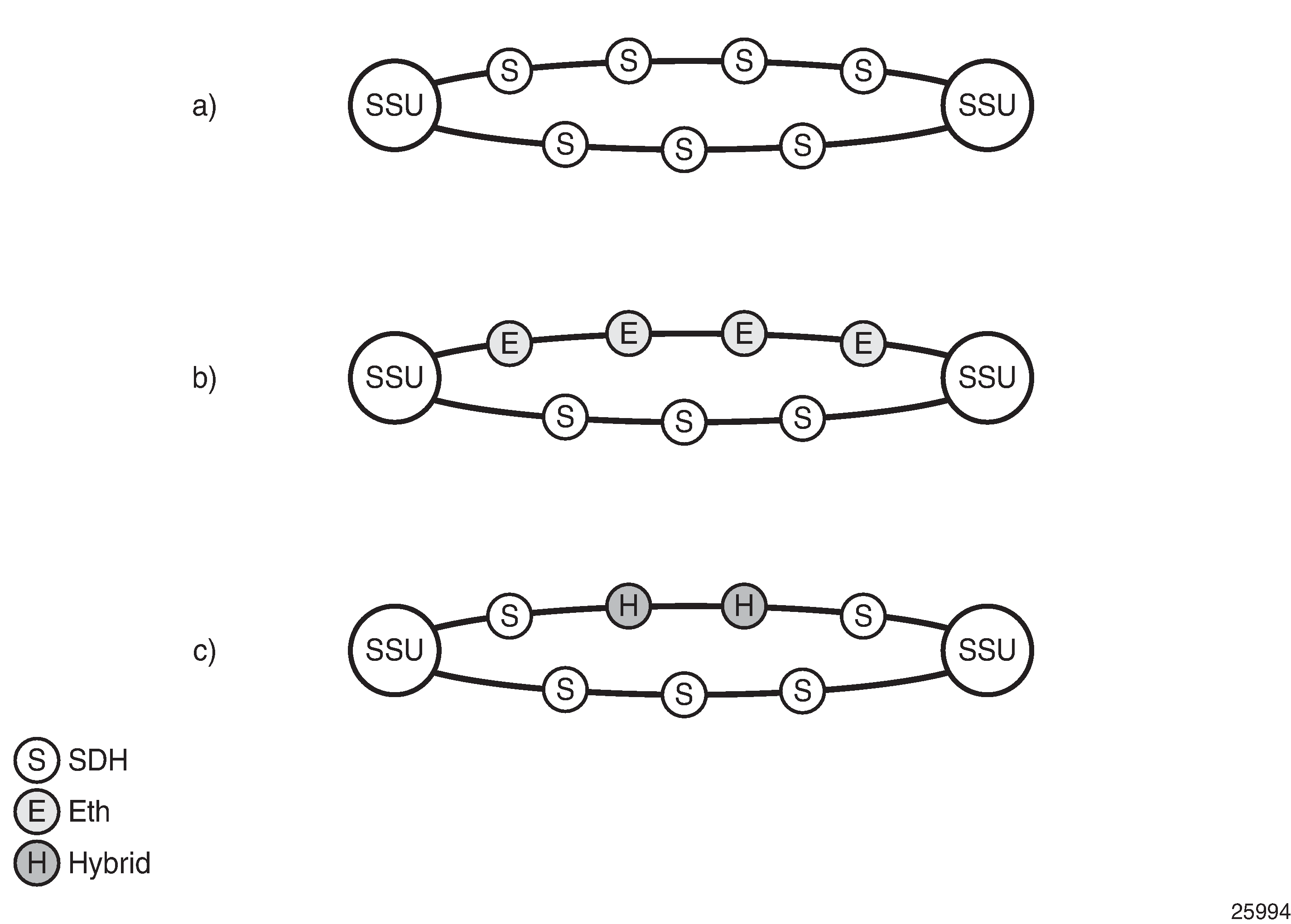
The advantage of using SyncE, as compared to methods relying on sending timing information in packets over an unlocked physical layer, is that SyncE is not influenced by impairments introduced by the higher levels of the networking technology (packet loss, packet delay variation). Therefore, the frequency accuracy and stability may be expected to exceed those of networks with unsynchronized physical layers. In addition, SyncE was designed to integrate into any existing SONET/SDH synchronization distribution architecture to allow for the easy migration from the traditional to the new synchronous interfaces. SyncE includes the concept of a hybrid switch which supports the interworking of synchronization distribution through SONET/SDH and the SyncE interfaces at the same time.
Many Tier 1 carriers are looking to migrate their synchronization infrastructure to a familiar and manageable model. In order to enable rapid migration of these networks, SyncE may be the easiest to deploy in order to ensure robust frequency synchronization.
Central Synchronization Sub-System
The timing subsystem for the SR OS platforms has a central clock located on the Control Processor Module (CPM). The timing subsystem performs many of the duties of the network element clock as defined by Telcordia GR-1244 and ITU-T G.781.
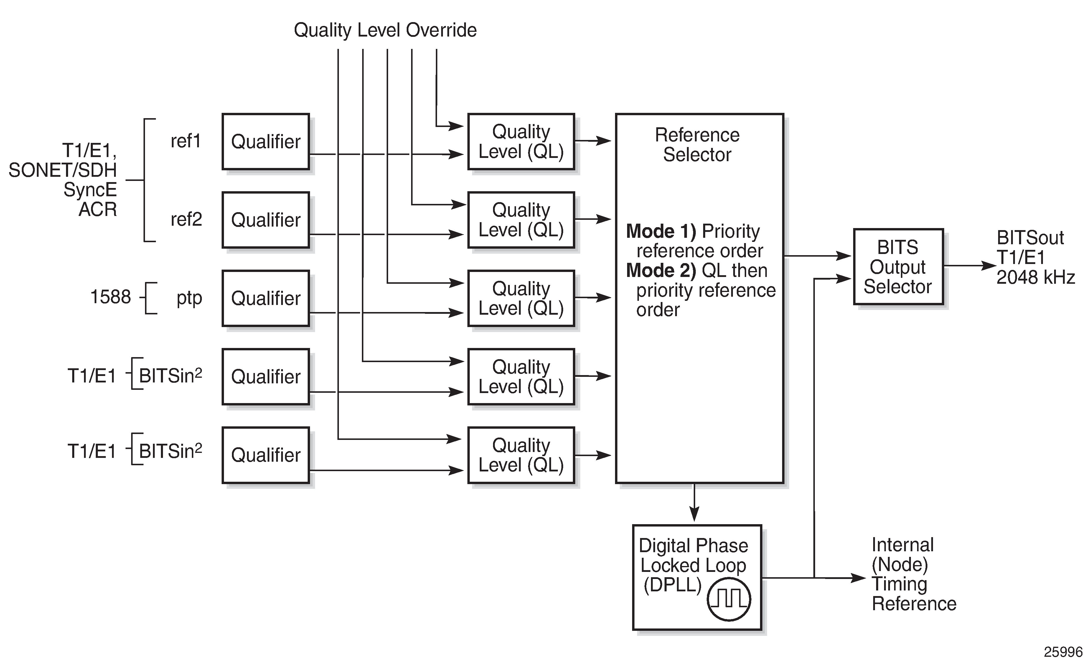
The system can select from up to three (7950 XRS) or four (7450 ESS and 7750 SR) timing inputs to train the local oscillator. The priority order of these references must be specified. This is a simple ordered list of inputs: {BITS [Building Integrated Timing Source], ref1, ref2, PTP [Precision Time Protocol]}. The CPM clock output has the ability to drive the clocking for all line cards in the system. The SR OS platforms support selection of the node reference using Quality Level (QL) indications.
The recovered clock is able to derive its timing from any of the following:
OC3/STM1, OC12/STM4, OC48/STM16, OC192/STM64 ports (7450 ESS and 7750 SR only)
T1/E1 CES channel (adaptive clocking) (7750 SR only)
SyncE ports
T1/E1 ports (7750 SR only)
BITS port on a channelized OC3/STM1 CES CMA (7750 SR-c12 only)
BITS port on the CPM, CFM, or CCM module
10GE ports in WAN PHY mode
IEEE 1588v2 slave port (PTP) (7450 ESS and 7750 SR only)
On 7750 SR-12 and 7750 SR-7 systems with redundant CPMs, the system has two BITS input ports (one per CPM). On the 7750 SRc-4 systems, there are two BITS input ports on the chassis front plate. These BITS input ports provide redundant synchronization inputs from an external BITS/SSU. However, the 7750 SR-c12 does not support BITS input port redundancy or BITS out.
All settings of the signal characteristics for the BITS input apply to both ports. When the active CPM considers the BITS input as a possible reference, it will consider first the BITS input port on the active CPM followed the BITS input port on the standby CPM in that relative priority order. This relative priority order is in addition to the user definable ref-order. For example, a ref-order of ‛bits-ref1-ref2-ptp’ would actually be BITS in (active CPM) followed by BITS in (standby CPM) followed by ref1 followed by ref2 followed by PTP. When ql-selection is enabled, then the QL of each BITS input port is viewed independently. The higher QL source is chosen.
On the 7750 SR-c4 platform CFM, there are two BITS input ports and two BITS output ports on this one module. These two ports are provided for BITS redundancy for the chassis. All settings of the signal characteristics for the BITS input apply to both ports. This includes the ql-override setting. When the CFM considers the BITS input as a possible reference, it will consider first the BITS input port ‟bits1” followed the BITS input port ‟bits2” in that relative priority order. This relative priority order is in addition to the user definable ref-order. For example, a ref-order of ‛bits-ref1-ref2’ would actually be ‟bits1” followed by ‟bits2” followed by ref1 followed by ref2. When ql-selection is enabled, then the QL of each BITS input port is viewed independently. The higher QL source is chosen.
The BITS output ports deliver a unfiltered recovered line clock from a SR/ESS port directly to a dedicated timing device in the facility (BITS or Standalone Synchronization Equipment (SASE) device). The signal selected will be one of ref1 or ref2. It cannot be the BITS input port signal nor can it be the output of the central clock.
When QL selection mode is disabled, then the reversion setting controls when the central clock can re-select a previously failed reference.
Revertive, Non-Revertive Timing Reference Switching Operation shows the selection followed for two references in both revertive and non-revertive modes.
Status of Reference A |
Status of Reference B |
Active Reference Non-revertive Case |
Active Reference Revertive Case |
|---|---|---|---|
OK |
OK |
A |
A |
Failed |
OK |
B |
B |
OK |
OK |
B |
A |
OK |
Failed |
A |
A |
OK |
OK |
A |
A |
Failed |
Failed |
holdover |
holdover |
OK |
Failed |
A |
A |
Failed |
Failed |
holdover |
holdover |
Failed |
OK |
B |
B |
Failed |
Failed |
holdover |
holdover |
OK |
OK |
A or B |
A |
Synchronization Status Messages (SSM)
SSM provides a mechanism to allow the synchronization distribution network to both determine the quality level of the clock sourcing a given synchronization trail and to allow a network element to select the best of multiple input synchronization trails. Synchronization Status messages have been defined for various transport protocols including SONET/SDH, T1/E1, and SyncE, for interaction with office clocks, such as BITS or SSUs (synchronization supply unit) and embedded network element clocks.
SSM allows equipment to autonomously provision and reconfigure (by reference switching) their synchronization references, while helping to avoid the creation of timing loops. These messages are particularly useful to allow synchronization reconfigurations when timing is distributed in both directions around a ring.
In SyncE, the SSM is provided through the Ethernet Synchronization Messaging Channel (ESMC). This mechanism uses Ethernet OAM PDU to exchange the Quality Level values over the SyncE link.
SyncE Chains
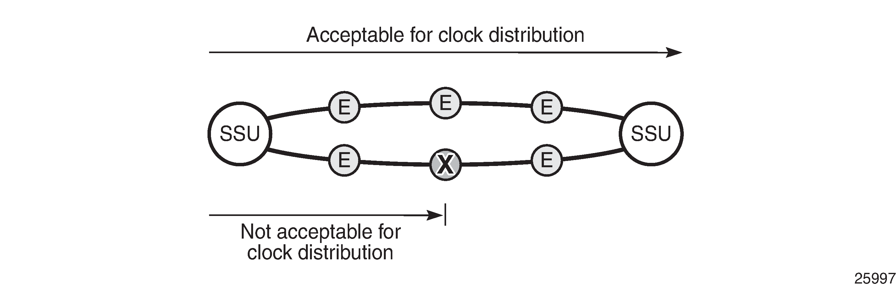
Transmission of a reference clock through a chain of Ethernet equipment requires that all of the equipment support SyncE.
A single piece of equipment not capable of SyncE breaks the chain as shown in Network Considerations for Ethernet Timing Distribution. Ethernet frames will still get through but downstream devices will recognize that the signal is out of pull-in range so they can not use it for reference.
Configuration
Configuration 1 - QL-Selection Mode Disabled
The following example shows the configuration options for SyncE when ql-selection mode is disabled. Generally, North American SONET networks do not use the automatic reference selection mechanisms. If SyncE is being added into such a network, it would likely have ql-selection set to disabled.
*A:PE-1# configure card 1 mda 1
  - mda <mda-slot>
  - no mda <mda-slot>

 <mda-slot>           : [1..2]

      access          + Configure access MDA parameters
      atm             + Configure ATM MDA parameters
      clock-mode      - Configure clock mode and timestamp frequency
      egress          + Configure egress MDA parameters
      egress-xpl      + Configure egress MDA XPL interface error parameters
 [no] fail-on-error   - Configure the behavior of the MDA state when an error is
                        detected
 [no] hi-bw-mcast-src - Enable/disable allocation of resources for high bandwidth
                        multicast streams
      ingress         + Configure ingress MDA parameters
      ingress-xpl     + Configure ingress MDA XPL interface error parameters
 [no] mda-type        - Provisions/de-provisions an MDA to/from the device
                        configuration for the slot
      named-pool-mode + Enable/Disable named pool mode
      network         + Configure network MDA parameters
 [no] shutdown        - Administratively shut down an mda
 [no] sync-e          - Enable/Disable Synchronous Ethernet
SyncE is enabled on MDA 1 of card 1 as follows:
*A:PE-1# configure card 1 mda 1 sync-e
After syncE is enabled, the configuration of MDA 1 is as follows
*A:PE-1# configure card 1 mda 1
*A:PE-1>config>card>mda#             info detail
----------------------------------------------
            mda-type m4-10gb-xp-xfp
            sync-e
            named-pool-mode
                ingress
                    no named-pool-policy
                exit
                egress
                    no named-pool-policy
                exit
            exit
            ingress
            exit
            ingress-xpl
                threshold 1000
                window 60
            exit
            egress
                no hsmda-pool-policy
                hsmda-agg-queue-burst
                    no low-burst-multiplier
                    no high-burst-increase
                exit
            exit
            egress-xpl
                threshold 1000
                window 60
            exit
            no fail-on-error
            network
                ingress
                    pool default
                        no amber-alarm-threshold
                        no red-alarm-threshold
                        resv-cbs default
                        slope-policy "default"
                    exit
                    queue-policy "default"
                exit
                egress
                    pool default
                        no amber-alarm-threshold
                        no red-alarm-threshold
                        resv-cbs default
                        slope-policy "default"
                    exit
                exit
            exit
            access
                ingress
                    pool default
---snip---
The synchronous interface timing can be configured with the following parameters:
*A:PE-1# configure system sync-if-timing
  - sync-if-timing

     abort           - Discard the changes that have been made to sync interface
                       timing during a session
      begin           - Switch to edit mode for sync interface timing - use commit to
                        save or abort to discard the changes made in a session
      bits            + Configure parameters for the Building Integrated Timing
                        Supply (BITS)
      commit          - Save the changes made to sync interface timing during a session
      ptp             + Configure parameters for Precision Timing Protocol (PTP)
                        timing reference
 [no] ql-minimum      - Configure the minimum quality level of the input
 [no] ql-selection    - Enable/disable reference selection based on quality-level
 [no] ref-order       - Priority order of timing references
      ref1            + Configure parameters for the first timing reference
      ref2            + Configure parameters for the second timing reference
 [no] revert          - Revert/do not revert to a higher priority re-validated
                        reference source
 [no] wait-to-restore - Configure the wait-to-restore timer
The synchronous interface timing configuration parameters for the first timing reference ref1 are the following:
*A:PE-1# configure system sync-if-timing ref1
  - ref1

 [no] ql-override     - Override the quality level of a timing reference
 [no] shutdown        - Administratively shutdown the timing reference
 [no] source-port     - Configure the source port for the first timing reference
The synchronous interface timing for ref1 with source port 1/1/2 is configured as follows:
configure
    system
        sync-if-timing
            begin
            ref-order bits ref1             # default setting
            ref1
                source-port 1/1/2
                no shutdown
            exit
            bits
                interface-type ds1 esf      # default setting
                input
                    no shutdown
                exit
            exit
            revert
            commit
The detailed settings for the synchronous interface timing are as follows:
*A:PE-1>config>system>sync-if-timing# info detail
----------------------------------------------
            no ql-minimum
            no ql-selection
            ref-order bits ref1 ref2 ptp
            ref1
                source-port 1/1/2
                no shutdown
                no ql-override
            exit
            ref2
                shutdown
                no source-port
                no ql-override
            exit
            bits
                interface-type ds1 esf
                no ql-override
                input
                    no shutdown
                exit
                output
                    shutdown
                    line-length 110
                    no ql-minimum
                    source line-ref
                    no squelch
                exit
            exit
            ptp
                shutdown
                no ql-override
            exit
            revert
            no wait-to-restore
----------------------------------------------
*A:PE-1>config>system>sync-if-timing#
The following output displays the associated show information.
*A:PE-1# show system sync-if-timing

===============================================================================
System Interface Timing Operational Info
===============================================================================
System Status CPM A                : Master Locked
    Reference Input Mode           : Revertive
    Quality Level Selection        : Disabled
    Reference Selected             : ref1
    System Quality Level           : unknown
    Current Frequency Offset (ppm) : +0
    Input Minimum Quality Level    : none
    Wait to Restore Timer          : Disabled

Reference Order                    : bits ref1 ref2 ptp

Reference Mate CPM
    Qualified For Use              : No
        Not Qualified Due To       :     LOS
    Selected For Use               : No
        Not Selected Due To        :     not qualified

Reference Input 1
    Admin Status                   : up
    Rx Quality Level               : unknown
    Quality Level Override         : none
    Qualified For Use              : Yes
    Selected For Use               : Yes
    Source Port                    : 1/1/2

Reference Input 2
    Admin Status                   : down
    Rx Quality Level               : unknown
    Quality Level Override         : none
    Qualified For Use              : No
        Not Qualified Due To       :     disabled
    Selected For Use               : No
        Not Selected Due To        :     disabled
    Source Port                    : None

Reference BITS A
    Input Admin Status             : up
    Rx Quality Level               : failed
    Quality Level Override         : none
    Qualified For Use              : No
        Not Qualified Due To       :     LOS
    Selected For Use               : No
        Not Selected Due To        :     not qualified
    Interface Type                 : DS1
    Framing                        : ESF
    Line Coding                    : B8ZS
    Line Length                    : 0-110ft
    Output Admin Status            : down
    Output Minimum Quality Level   : none
    Output Source                  : line reference
    Output Reference Selected      : none
    Output Squelch                 : Disabled
    Tx Quality Level               : N/A

Reference PTP
    Admin Status                   : down
    Rx Quality Level               : failed
    Quality Level Override         : none
    Qualified For Use              : No
        Not Qualified Due To       :     disabled
    Selected For Use               : No
        Not Selected Due To        :     disabled
===============================================================================
*A:PE-1#
Configuration 2 - QL Selection Mode Enabled
The following example shows the configuration options for SyncE when ql-selection mode is enabled.
This is the normal case for European SDH networks.
SyncE is enabled as follows:
*A:PE-1# configure card 1 mda 1 sync-e
On port 1/1/2, the Synchronization Status Message (SSM) channel is configured to SDH, as follows:
*A:PE-1# configure port 1/1/2 ethernet ssm
  - ssm

 [no] code-type       - Set the SSM channel to either use sonet or sdh
 [no] shutdown        - Enable/Disable SSM
 [no] tx-dus          - Enable/disable always transmit 0xF (dus/dnu) in SSM
                        messaging channel

configure port 1/1/2 ethernet ssm code-type sdh
configure port 1/1/2 ethernet ssm no shutdown
The synchronization interface timing is configured as follows with timing reference ref1:
configure
    system
        sync-if-timing
            begin
            ql-selection
            ref-order bits ref1             # default setting
            ref1
                source-port 1/1/2
                no shutdown
            exit
            bits
                interface-type e1 pcm31crc  # for Europe
                ql-override prc             # for Europe
                input
                    no shutdown
                exit
            exit
            revert
            commit
The European QL-codes are the following: prc, ssu-a, ssu-b, sec, eec1. For North America, the QL-codes are: prs, stu, st2, tnc, st3e, st3, eec2. In this configuration example, Primary Reference Clock (PRC) is chosen.
*A:PE-1>config>system>sync-if-timing# info detail
----------------------------------------------
            no ql-minimum
            ql-selection
            ref-order bits ref1 ref2 ptp
            ref1
                source-port 1/1/2
                no shutdown
                no ql-override
            exit
            ref2
                shutdown
                no source-port
                no ql-override
            exit
            bits
                interface-type e1 pcm31crc
                ssm-bit 8
                ql-override prc
                input
                    no shutdown
                exit
                output
                    shutdown
                    no ql-minimum
                    source line-ref
                    no squelch
                exit
            exit
            ptp
                shutdown
                no ql-override
            exit
            revert
            no wait-to-restore
----------------------------------------------
The following output displays the associated show information.
*A:PE-1# show system sync-if-timing

===============================================================================
System Interface Timing Operational Info
===============================================================================
System Status CPM A                : Master Holdover
    Reference Input Mode           : Revertive
    Quality Level Selection        : Enabled
    Reference Selected             : none
    System Quality Level           : st3
    Current Frequency Offset (ppm) : +0
    Input Minimum Quality Level    : none
    Wait to Restore Timer          : Disabled

Reference Order                    : bits ref1 ref2 ptp

Reference Mate CPM
    Qualified For Use              : No
        Not Qualified Due To       :     LOS
    Selected For Use               : No
        Not Selected Due To        :     not qualified

Reference Input 1
    Admin Status                   : up
    Rx Quality Level               : failed
    Quality Level Override         : none
    Qualified For Use              : Yes
    Selected For Use               : No
        Not Selected Due To        :     ssm quality
    Source Port                    : 1/1/2

Reference Input 2
    Admin Status                   : down
    Rx Quality Level               : unknown
    Quality Level Override         : none
    Qualified For Use              : No
        Not Qualified Due To       :     disabled
    Selected For Use               : No
        Not Selected Due To        :     disabled
    Source Port                    : None

Reference BITS A
    Input Admin Status             : up
    Rx Quality Level               : failed
    Quality Level Override         : prc
    Qualified For Use              : No
        Not Qualified Due To       :     LOS
    Selected For Use               : No
        Not Selected Due To        :     not qualified
    Interface Type                 : E1
    Framing                        : PCM31 CRC
    Line Coding                    : HDB3
    Line Length                    : 8
    Output Admin Status            : down
    Output Minimum Quality Level   : none
    Output Source                  : line reference
    Output Reference Selected      : none
    Output Squelch                 : Disabled
    Tx Quality Level               : N/A

Reference PTP
    Admin Status                   : down
    Rx Quality Level               : failed
    Quality Level Override         : none
    Qualified For Use              : No
        Not Qualified Due To       :     disabled
    Selected For Use               : No
        Not Selected Due To        :     disabled
===============================================================================
*A:PE-1#
Conclusion
With the world rapidly transitioning to IP/MPLS-based NGNs with Ethernet as the transport medium of choice, there is an increasing need to enhance services and capabilities while still leveraging existing infrastructure, thereby easing the transition while continuing to increase revenue and reduce the Total Cost of Ownership (TCO). In areas such as mobile backhaul, TDM CES etc., these requirements create a need for SONET/SDH-like frequency synchronization capability in the inherently asynchronous Ethernet network.
SyncE, natively supported on the Nokia SR OS routers, is an ITU-T standardized PHY-level way of transmitting frequency synchronization across Ethernet packet networks that fulfills that need in a reliable, secure, scalable, efficient, and cost-effective manner. It allows service providers to keep existing revenue streams alive and create new ones while simplifying the network design and reducing TCO.