BGP Signaled Segment Routing Policy
This chapter describes BGP Signaled Segment Routing Policy.
Topics in this chapter include:
Applicability
The information and configuration contained in this chapter are based on SR OS Release 21.7.R1.
Overview
Segment Routing (SR) allows a head-end node to steer a packet flow along a source-routed path. SR policy is a generic framework that describes the procedures and processes that a head-end node carries out when instantiating such a path. The SR policy consists of an ordered list of segments on a node, sufficient to implement a traffic-engineered path. The segments can have any type of Segment Identifier (SID), including Adjacency-SIDs, Node-SIDs, and Anycast-SIDs. The head-end can then steer traffic, using the SR policy as appropriate.
An SR policy can define one or multiple candidate paths. When explicit candidate paths are used, each path contains one or more segment lists, where each segment list contains the ordered set of segments (identified by their unique SID) required to provide the source-routed path from head-end to destination. When a candidate path contains multiple segment lists, each is assigned a weight for the purpose of weighted load-balancing. Candidate paths can be instantiated using a variety of ways, including Path Computation Element Protocol (PCEP), BGP, or local configuration. This chapter describes the use of BGP to advertise SR policy candidate paths. The term "BGP SR policy" is interchangeably used with "BGP SR TE policy".
SR policy overview
An SR policy is identified through the tuple {head-end, color, endpoint}.
The head-end is the node where the SR policy is instantiated, and the node that is responsible for steering traffic, using the SR policy with the relevant SID stack. From the perspective of the head-end, the SR policy can be identified using the {color, endpoint} tuple.
The color is a fundamental part of the SR policy and forms part of the Network Layer Reachability Information (NLRI). The color is a 32-bit numerical value that a head-end uses to associate the SR policy with a characteristic, such as low-latency or high-throughput.
The endpoint is the destination in the SR policy specified as an IPv4 or IPv6 address, although "wildcard" destinations can be used and are described later in this chapter.
Color is also a 32-bit transitive extended community originally defined in draft-ietf-idr-tunnel-encaps that can be attached to a BGP update message, in order to associate it with a corresponding SR policy. For example, if head-end H learns a BGP route R with {next-hop N, color extended community C, and VPN label V} and head-end H has a valid SR policy P to {endpoint N, color C}, it can associate BGP route R with the SR policy P. When H receives packets with a destination matching BGP route R, it forwards them using the instructions contained within SR policy P.
SR policy NLRI
The BGP address family "SR TE policy" (SAFI 73) is defined to advertise a candidate path for an SR policy in BGP and is carried in an update message using BGP multiprotocol extensions. The AFI must be IPv4 (AFI=1) or IPv6 (AFI=2). An SR policy candidate path may be advertised from a centralized controller, or it may be advertised by a router; for example, an egress router advertising paths to itself. SR TE policy NLRI shows the structure of the SR TE policy NLRI.
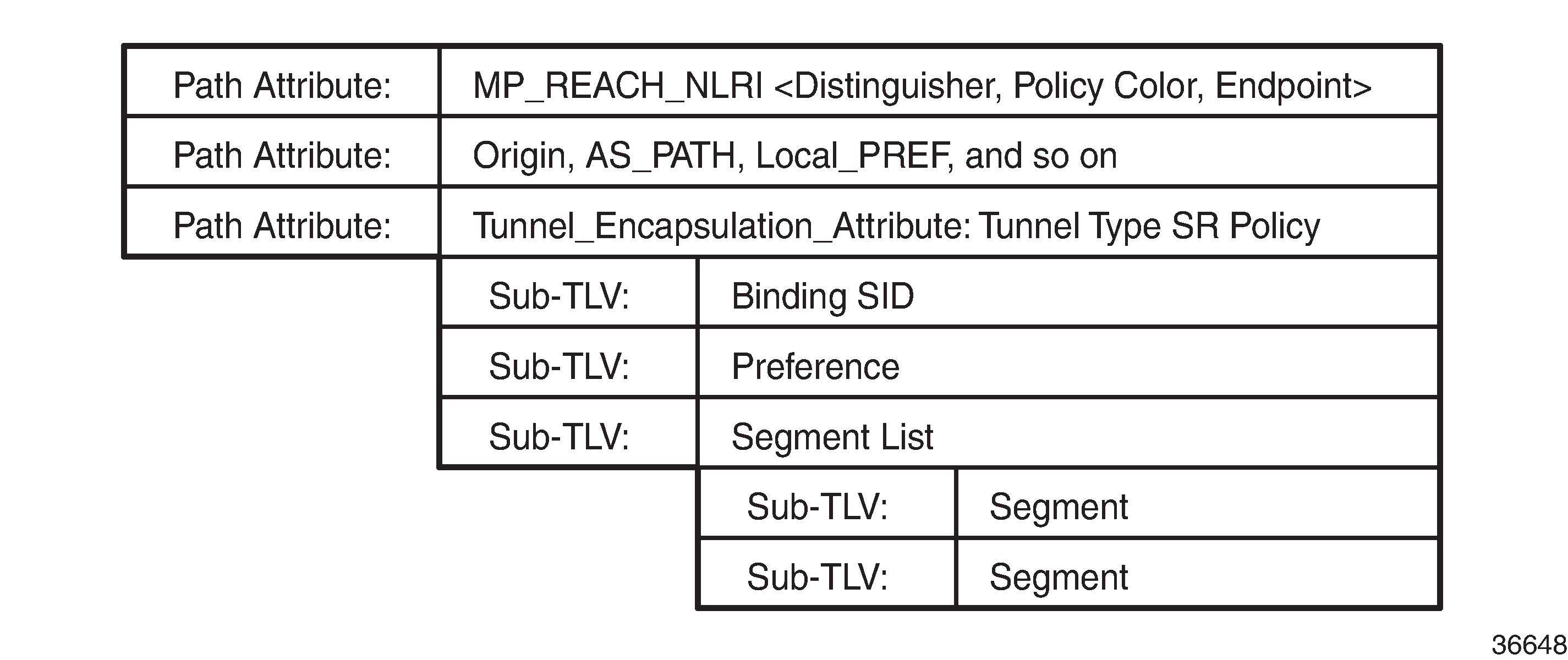
The SR TE policy NLRI is used to identify an SR policy candidate path and, because it uses MP-BGP, it is carried in an MP_REACH/UNREACH_NLRI path attribute. The NLRI contains the color and endpoint values described previously, and a distinguisher. The distinguisher is an integer value in the range 1 to 4294967295 that serves to make the SR policy unique from an NLRI perspective. The SR TE policy NLRI uses standard BGP propagation and best-path selection; a unique distinguisher ensures that best-path selection does not unnecessarily suppress SR policy advertisements.
Multiple candidate paths can exist for an SR policy, although only one path can be selected as the best path of the SR policy and become the active path. If several candidate paths of the same SR policy (endpoint, color) are advertised via BGP SR TE policy to the same head-end, unique distinguishers for each NLRI are recommended. In SR OS Release 21.7.R1, only a single candidate path is supported for an SR policy.
The other parameters of the SR policy candidate path are carried as sub-TLVs of the Tunnel Encapsulation Attribute (draft-ietf-idr-tunnel-encaps) using a tunnel-type known as "SR policy", and are described following.
Binding SID
The SR architecture defines the use of a Binding SID (BSID). A BSID is bound to an SR policy, and packets arriving at a node with an active label equal to the BSID are steered using that SR policy. This action may mean swapping the incoming active label with one or more outgoing labels representing the SR policy path.
When used in this manner, the Binding SID serves as an anchor point, sometimes referred to as a "BSID anchor", that allows one domain to be isolated from another domain. This is shown in Binding SID (BSID) anchor, where ABR-3 is acting as a BSID anchor between the aggregation domain and the core domain. ABR-3 has an SR policy to PE-7 with the path P-4-P-5-P-6 and with a BSID of 1000. The PE-1 resulting SR policy to PE-7 consists of the path {Node-SID ABR-3, 1000, Node-SID PE-7} and a BSID of 500. When a packet is forwarded by the SR policy on PE-1 and arrives at ABR-3, it pops the Node-SID ABR-3 label, and swaps label 1000 for the label stack {P-4, P-5, P-6} of the SR policy on ABR-3.
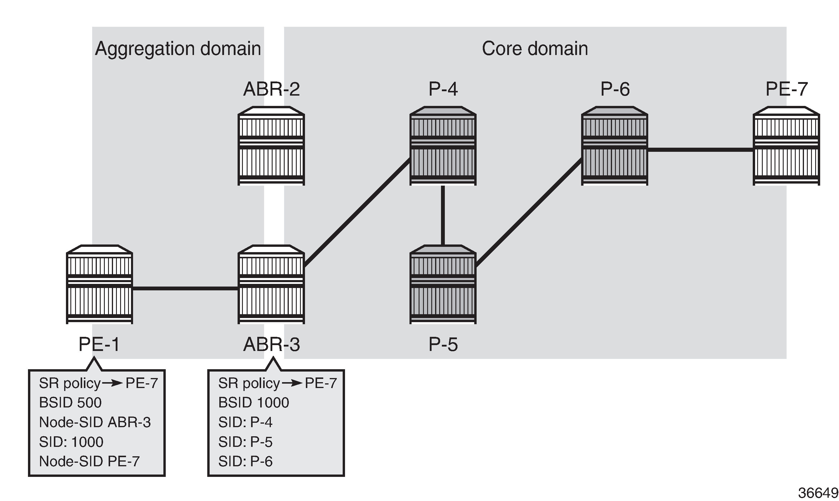
The BSID serves as an anchor point, which allows one domain to be isolated from the churn of another domain. If something changes in the path P-4-P-5-P-6, ABR-3 can repair the path locally without needing to change the BSID value known at PE-1. PE-1 is therefore protected from the churn in the core domain. The BSID also serves to reduce the number of segments/labels that the head-end needs to impose an end-to-end traffic-engineered path.
Segment list
A segment list sub-TLV encodes a single path toward the endpoint. Multiple segment list sub-TLVs may be included in each SR policy. Each segment list sub-TLV may contain multiple segment sub-TLVs and may carry a weight sub-TLV. Each segment sub-TLV describes a single segment in a segment list, and multiple segments may be concatenated to constitute an end-to-end path of the SR policy.
There are several types of the segment sub-TLV, allowing for the segment to be expressed as a variant of IPv4/IPv6 node address or local/remote address, and with a SID in the form of an MPLS label or IPv6 address. This chapter focuses only on the Type A encoding, which is represented as a SID in the form of an MPLS label. The SID contained within each segment sub-TLV can be any form of SID, including Node-SID, Adjacency-SID, Anycast-SID, or Binding SID.
The optional weight sub-TLV is used to implement (weighted) load-balancing in the presence of multiple segment lists. By default, SR OS assigns a weight value of 1 to each segment list.
Preference
The preference sub-TLV is used to indicate the preference of a candidate path in relation to other candidate paths. Multiple candidate paths can exist in an SR policy, but only one candidate path can be selected as the best and active path. When multiple candidate paths exist that are considered valid, the candidate path with the highest preference is selected. The default value of the preference is 100. If multiple paths have the same preference, the protocol origin (PCEP, BGP, local configuration) may be considered, followed by the lower value of originator, followed by the higher value of discriminator.
Example topology
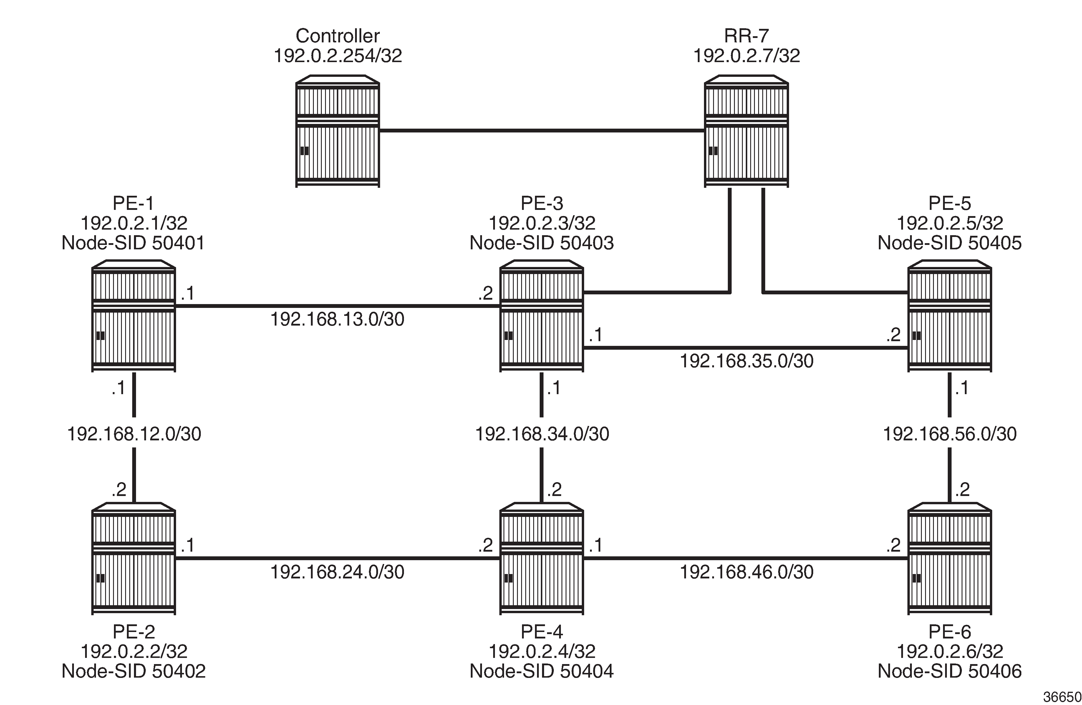
The topology in Example topology shows the use of BGP SR TE policy within this chapter. All PE routers within the example topology and the Route Reflector (RR-7) form part of Autonomous System 64496 and belong to the same IS-IS Level-2 area. All IGP link metrics are 100 and are symmetric. SR is enabled within the domain, and the associated Node-SIDs are shown in Example topology (Adj-SIDs are not shown for the purpose of clarity). The SRGB in use is {50000-54999}. All PE routers are clients of the Route Reflector for multiple address families including SR TE policy.
The example topology also has an additional router simulating a controller, which uses static routing for IP connectivity. This is the point from which SR policies are advertised into BGP, although as previously described, SR policies can be advertised into BGP by a controller or a router. The controller peers in the SR TE policy address family with the Route Reflector, which in turn reflects those routes to its clients.
Configuration
An SR policy can be statically (CLI) configured locally on a head-end or dynamically learned by a head-end through BGP SR TE policy route. For SR OS to obtain an SR TE policy route, that route needs to be configured locally as a static SR policy. This chapter provides an example of the instantiation of an SR policy using static configuration on the head-end, but thereafter focuses on the instantiation of SR policies learned by it through BGP SR TE policy. The same static SR policy configuration is used regardless of whether it is for advertising that SR policy into BGP to the head-end, or applying it at that local head-end to forward traffic.
Segment Routing Local Block
A BSID may be either a local SID or a global SID. In general, and for the use-cases in this chapter, BSIDs are local SIDs, so a BSID needs to be within the range of a locally-configured Segment Routing Local Block (SRLB). SRLBs are reserved label blocks used for specific local purposes, such as SR policy BSIDs, Adjacency Set SIDs, and static Adjacency SIDs. A dedicated SRLB is required per application and has only local significance, so the same values can be used on all SR routers in the domain. Ranges for each SRLB are taken from the dynamic label range. The following configuration allocates labels 100000 to109999 to the SRLB "SRLB-BSID":
# on all nodes:
configure
    router Base
        mpls-labels
            reserved-label-block "SRLB-BSID"
                start-label 100000 end-label 109999
             exit
        exit
    exit
exit
After the SRLB is defined, it is dedicated to the specific application, which in this case is SR policies. When the reserved-label-block is assigned, sr-policies must be enabled (no shutdown), as follows:
# on all nodes:
configure
    router Base
        segment-routing
            sr-policies
                reserved-label-block "SRLB-BSID"
                no shutdown
            exit
        exit
    exit
exit
The preceding configuration is applied to all SR routers in the domain.
Static SR policy
As previously described, SR policies can be statically (CLI) configured locally on a head-end or dynamically learned by a head-end through BGP SR TE policy route. In this section, the necessary steps are shown for the instantiation of an SR policy using static configuration locally on PE-1 as the head-end.
The following output shows the configuration of a static SR policy at PE-1 (192.0.2.1) with an endpoint of PE-5 (192.0.2.5).
# on PE-1:
configure
    router Base
        segment-routing
            sr-policies
                static-policy "PE-1-PE-5-color600" create
                    binding-sid 100002
                    color 600
                    distinguisher 600001005
                    endpoint 192.0.2.5
                    head-end local
                    segment-list 1 create
                        segment 1 create
                            mpls-label 50402    # node-SID PE-2
                        exit
                        segment 2 create
                            mpls-label 150024   # adj-SID int-PE-2-PE-4
                        exit
                        segment 3 create
                            mpls-label 150046   # adj-SID int-PE-4-PE-6
                        exit
                        segment 4 create
                            mpls-label 50405    # node-SID PE-5
                        exit
                        no shutdown             # enable segment list
                    exit
                    no shutdown                 # enable static SR policy
                exit
            exit
        exit
    exit
exit
The static SR policy is initially created within the sr-policies context and begins by assigning a binding-sid of 100002. In this example, the SR policy is local to PE-1, and the BSID value is therefore within the range of the PE-1 SRLB. If this static SR policy were to be advertised into BGP, the advertised BSID value must be in the range of the SRLB configured on the target head-end.
The next three parameters are the color, distinguisher, and endpoint that constitute the SR policy NLRI. The SR policy color is 600, and is a 4-octet value that can be configured in the range 1 to 4294967295. The distinguisher is also a 4-octet value with the same range and is configured as 600001005 (representing the color plus the last octet of the head-end and endpoint addresses). As previously described, the purpose of the distinguisher is to make the SR policy unique from an NLRI perspective, such that if multiple candidate paths of the same SR policy (endpoint, color) are advertised, they are not suppressed by any BGP best-path selection algorithm.
The endpoint is the IPv4 or IPv6 address of the destination for the SR policy and is configured as the PE-5 address 192.0.2.5. There are special circumstances where the value 0.0.0.0 or 0::0 is allowed as an endpoint. This is referred to as color-only steering and is described later in this chapter.
The head-end is the target node where the SR policy is to be instantiated. If the SR policy is statically configured on the head-end for forwarding of traffic locally using that SR policy, the value local is used, as shown in this example. If the SR policy is configured somewhere other than on the head-end, and advertised into BGP toward the head-end, the value of the head-end parameter is the IPv4 address of that head-end. When the SR policy is advertised into BGP, the head-end address is also encoded as an IPv4 address-specific Route-Target Extended Community, which allows for potential constraining of route propagation.
The final parameter is the segment list. The preceding configuration output shows the segment list consisting of four segments, which represent the path using the following SIDs:
Segment 1 SID is 50402, which is the Node-SID of PE-2
Segment 2 SID is 150024, representing the PE-2 Adj-SID for the link PE-2-PE-4
Segment 3 SID is 150046, representing the PE-4 Adj-SID for the link PE-4-PE-6
Segment 4 SID is 50405, which is the Node-SID of PE-5.
A more optimal SID stack is achievable in this topology, but the configured segment list shows the use of both Node- and Adj-SIDs on a loose or strict hop basis. The segment list has an optional weight parameter used for load-balancing across multiple segment lists. In this example, only a single segment list exists, so the default weight value of 1 is retained.
Finally, both the segment list and the static SR policy are enabled (no shutdown). The following output shows the operational state of the static SR policy. The Active field shows whether this candidate path is the selected path in the presence of multiple candidate paths. The SR policy segment list is considered valid if the head-end is able to perform path resolution for the first SID in the segment list into one or more outgoing interfaces and next-hops. The segment 1 label is 50402, and the State is shown as resolved-up, indicating that this is a valid segment list.
*A:PE-1# show router segment-routing sr-policies static

===============================================================================
SR-Policies Path
===============================================================================
-------------------------------------------------------------------------------
Active          : YesOwner           : static
Color           : 600
Head            : 0.0.0.0               Endpoint Addr   : 192.0.2.5
RD              : 600001005             Preference      : 100
BSID            : 100002
TunnelId        : 917506                Age             : 73
Origin ASN      : 0                     Origin          : 0.0.0.0
NumReEval       : 0                     ReEvalReason    : none
NumActPathChange: 0                     Last Change     : 09/13/2021 15:11:33
Maintenance Policy: N/A

Path Segment Lists:
Segment-List    : 1                     Weight          : 1
S-BFD State     : Down                  S-BFD Transitio*: 0
Num Segments    : 4                     Last Change     : 09/13/2021 15:00:54
  Seg 1 Label   : 50402                 State           : resolved-up
  Seg 2 Label   : 150024                State           : N/A
  Seg 3 Label   : 150046                State           : N/A
  Seg 4 Label   : 50405                 State           : N/A

===============================================================================
* indicates that the corresponding row element may have been truncated.
If the SR policy is considered valid, it is populated in the tunnel table with an owner of sr-policy. The entry indicates the destination and color, and always has a metric value of 0 regardless of how the SR policy is instantiated. The metric value of 0 is used because there is no effective way for the head-end to determine a more reflective value for an SR policy when learned through BGP SR TE policy or statically configured.
*A:PE-1# show router tunnel-table 192.0.2.5 protocol sr-policy

===============================================================================
IPv4 Tunnel Table (Router: Base)
===============================================================================
Destination           Owner     Encap TunnelId  Pref   Nexthop        Metric
   Color
-------------------------------------------------------------------------------
192.0.2.5/32sr-policy MPLS  917506    14     192.0.2.2      0
   600
-------------------------------------------------------------------------------
Flags: B = BGP or MPLS backup hop available
       L = Loop-Free Alternate (LFA) hop available
       E = Inactive best-external BGP route
       k = RIB-API or Forwarding Policy backup hop
===============================================================================
Traffic steering using SR policies
A head-end can potentially steer traffic using an SR policy as a midpoint (or BSID anchor) or as an ingress router using color-based traffic steering:
At a midpoint or BSID anchor, if an incoming packet has an active label that matches the BSID of a valid SR policy, the incoming label is swapped for the labels contained in the active path of that SR policy, and traffic is forwarded along that path.
At an ingress router, if a BGP or service route is received containing a Color Extended Community with a value corresponding to a valid local SR policy, and the endpoint of that SR policy matches the next-hop of the BGP/service route, traffic is forwarded into the associated SR policy.
This sub-section discusses the use of the Color Extended Community to implement traffic steering at an ingress router, and begins with an overview of the structure of the Color Extended Community.
The Color Extended Community has two flags, known as the Color-Only (CO) bits, that allow for a head-end to optionally steer traffic using an SR policy, without the need to explicitly define an SR policy endpoint that matches the next-hop of a BGP or service route. In this case, the endpoint can be the null address (0.0.0.0 for IPv4 and 0::0 for IPv6) and traffic is steered by an SR policy based on correlation of color. Use of CO bits describes the destination steering options based on the setting of the Color-Only (CO) bits.
CO bits=00 |
CO bits=01 |
CO bits=10 |
|---|---|---|
If there is a valid SR policy (N, C), where N is the IPv4 or IPv6 endpoint address and C is a color, steer using SR policy (N, C); |
If there is a valid SR policy (N, C), where N is the IPv4 or IPv6 endpoint address and C is a color, steer using SR policy (N, C); |
If there is a valid SR policy (N, C), where N is the IPv4 or IPv6 endpoint address and C is a color, steer using SR policy (N, C); |
Else, steer on the IGP path to the next-hop N |
Else, if there is a valid SR policy (null endpoint, C) of the same address family as N, steer using SR policy (null endpoint, C); |
Else, if there is a valid SR policy (null endpoint, C) of the same address family as N, steer using SR policy (null endpoint, C); |
Else, if there is any valid SR policy (any address family null endpoint, C), steer using SR policy (any null endpoint, C); |
Else, if there is any valid SR policy (any address family null endpoint, C), steer using SR policy (any null endpoint, C); |
|
Else, steer on the IGP path to the next-hop N |
Else, if there is any valid SR policy (any endpoint, C) of the same address family as N, steer using SR policy (any endpoint, C); |
|
Else, if there is any valid SR policy (any address family endpoint, C), steer using SR policy (any address family endpoint, C); |
||
Else, steer on the IGP path to the next-hop N |
Per-destination traffic steering
When incoming packets match a BGP/service route with a next-hop that resolves to an SR policy, it is referred to as per-destination traffic steering. The previously configured static SR policy at PE-1 with color 600 is used to show how it is applied. A VPRN service (600) is extended between PE-1 and PE-5 with import/export Route-Target 64496:600, and with the auto-bind-tunnel resolution-filter at PE-1 set to SR policy (the complete VPRN service configuration is not shown for conciseness).
# on PE-1:
configure
    service
        vprn 600 name "VPRN_600" customer 1 create
            vrf-import "vrf600-import"
            vrf-export "vrf600-export"
            autonomous-system 64496
            route-distinguisher 64496:600
            auto-bind-tunnel
                resolution-filter
                    sr-policy
                exit
                resolution filter
            exit
            ---snip---
        exit
    exit
exit
A CE router is locally connected to PE-5 and advertises prefix 10.148.5.0/24 to IPv4 BGP, which PE-5 subsequently advertises as a VPN-IPv4 route. In addition to attaching the Route-Target Extended Community to the VPN-IPv4 route, PE-5 also attaches a Color Extended Community with value 600. The PE-5 VRF export policy is shown following. When configuring the Color Extended Community, the syntax "color:co:value" is used. Therefore, in the example configuration, the CO bits are 00 and the color value is 600.
# on PE-5:
configure
    router Base
        policy-options
            begin
            community "vrf600-export"
                members "target:64496:600"
            exit
            community "vrf600-sr-policy"
                members "color:00:600"
            exit
            policy-statement "vrf600-export"
                entry 10
                    from
                        protocol bgp
                    exit
                    to
                        protocol bgp-vpn
                    exit
                    action accept
                        community add "vrf600-export" "vrf600-sr-policy"
                    exit
                exit
            exit
            commit
        exit
    exit
exit
At PE-1, the VPN-IPv4 route with {next-hop PE-5, color extended community 600} resolves to the PE-1 static SR policy with {endpoint PE-5, color 600}. It is imported into the VPRN route-table with an indication that it is resolved to the SR policy with tunnel ID 917506, which is the tunnel ID of the previously configured static SR policy. Traffic from PE-1 to PE-5 is therefore forwarded into the SR policy using the label stack defined in the segment list.
*A:PE-1# show router 600 route-table 10.148.5.0/24

===============================================================================
Route Table (Service: 600)
===============================================================================
Dest Prefix[Flags]                            Type    Proto     Age        Pref
      Next Hop[Interface Name]                                    Metric
-------------------------------------------------------------------------------
10.148.5.0/24                                 Remote  BGP VPN   00h02m26s  170
      192.0.2.5 (tunneled:SR-Policy:917506)                        0
-------------------------------------------------------------------------------
No. of Routes: 1
Flags: n = Number of times nexthop is repeated
       B = BGP backup route available
       L = LFA nexthop available
       S = Sticky ECMP requested
===============================================================================
Color-Only traffic steering
SR OS provides support for Color-Only traffic steering using a null endpoint SR policy, but its use is limited to unlabeled BGP address families because of the following. When an egress router advertises a downstream label in a labeled BGP update (VPN-IPv4/IPv6, EVPN, BGP Labeled Unicast, and so on) that egress router needs to see that label in received packets to be able to demultiplex into the relevant service/next-hop and forward traffic toward the destination. If a head-end is forwarding traffic using an SR policy with a null endpoint, that head-end is unaware of the egress router, so cannot impose the relevant downstream-advertised BGP/service label into the label stack.
The following example shows the configuration of Color-Only traffic steering. PE-5 advertises an IPv4 prefix 172.16.5.1/32 to PE-1 with the Color Extended Community 01:600. PE-1 intends to use the previously configured static SR policy to resolve this route. As described in Use of CO bits , with the CO-bits set to 01, the head-end uses an SR policy with (null endpoint, C) if no valid (N, C) SR policy exists.
*A:PE-5# show router bgp routes 172.16.5.1/32 hunt | match expression "Network|Nexthop|Community"
Network        : 172.16.5.1/32
Nexthop        : 192.0.2.5
Res. Nexthop   : n/a
Community      : color:01:600
At PE-1, the static SR policy to PE-5 is reconfigured such that the endpoint is no longer an explicit endpoint of 192.0.2.5 (PE-5), but instead uses a null endpoint (0.0.0.0).
# on PE-1:
configure
    router Base
        segment-routing
            sr-policies
                static-policy "PE-1-PE-5-color600" create
                    shutdown
                        endpoint 0.0.0.0
                    no shutdown
                exit
            exit
        exit
    exit
exit
Since PE-5 advertised an IPv4 BGP prefix, PE-1 also enables the use of BGP shortcuts, with a resolution filter that only permits the use of SR policy.
# on PE-1:
configure
    router Base
        bgp
            next-hop-resolution
                shortcut-tunnel
                    family ipv4
                        resolution-filter
                            sr-policy
                        exit
                        resolution filter
                    exit
                exit
            exit
        exit
    exit
exit
The tunnel table of PE-1 shows that there is a single SR policy active with a destination of 0.0.0.0/32 (null) and color 600.
*A:PE-1# show router tunnel-table protocol sr-policy

===============================================================================
IPv4 Tunnel Table (Router: Base)
===============================================================================
Destination           Owner     Encap TunnelId  Pref   Nexthop        Metric
   Color
-------------------------------------------------------------------------------
0.0.0.0/32            sr-policy MPLS  917507    14     192.0.2.2      0
   600
-------------------------------------------------------------------------------
Flags: B = BGP or MPLS backup hop available
       L = Loop-Free Alternate (LFA) hop available
       E = Inactive best-external BGP route
       k = RIB-API or Forwarding Policy backup hop
===============================================================================
The status of the IPv4 prefix 172.16.5.1/32 received from PE-5 is shown in the following output at PE-1. The output shows that the route is Used/Valid/Best, and that the resolving protocol is SR-POLICY, and the resolving NextHop is 0.0.0.0. Therefore, a BGP next-hop has been resolved to a null endpoint SR policy using the CO-bits.
*A:PE-1# show router bgp routes 172.16.5.1/32 detail
===============================================================================
 BGP Router ID:192.0.2.1        AS:64496       Local AS:64496
===============================================================================
 Legend -
 Status codes  : u - used, s - suppressed, h - history, d - decayed, * - valid
                 l - leaked, x - stale, > - best, b - backup, p - purge
 Origin codes  : i - IGP, e - EGP, ? - incomplete

===============================================================================
BGP IPv4 Routes
===============================================================================
Original Attributes

Network        : 172.16.5.1/32
Nexthop        : 192.0.2.5
Path Id        : None
From           : 192.0.2.7
Res. Protocol  : SR-POLICY              Res. Metric    : 0
Res. Nexthop   : 0.0.0.0 (SR-POLICY)
Local Pref.    : 100                    Interface Name : NotAvailable
Aggregator AS  : None                   Aggregator     : None
Atomic Aggr.   : Not Atomic             MED            : None
AIGP Metric    : None                   IGP Cost       : 0
Connector      : None
Community      : color:01:600
Cluster        : 192.0.2.7
Originator Id  : 192.0.2.5              Peer Router Id : 192.0.2.7
Fwd Class      : None                   Priority       : None
Flags          : Used Valid Best IGP In-RTM
Route Source   : Internal
AS-Path        : No As-Path
Route Tag      : 0
Neighbor-AS    : n/a
Orig Validation: NotFound
---snip---
Advertising SR policies into BGP
Before advertising SR policies into BGP, all previous static SR policy configuration is removed. The simulated controller acts as the source of BGP advertised SR policies, and when an SR OS router advertises SR policies into BGP they must first be statically configured to provide the relevant information to populate the BGP path attributes. The following static SR policy is applied at the controller representing a similar SR policy to that previously configured at PE-1. The SR policy has a head-end of PE-1 (192.0.2.1), an endpoint of PE-5 (192.0.2.5), and a color of 600. The segment list is modified slightly to represent a list of strict hops using Adj-SIDs along the path PE-1-PE-2-PE-4-PE-6-PE-5.
# on controller:
configure
    router Base
        segment-routing
            sr-policies
                static-policy "color600-PE-1-PE-5" create
                    binding-sid 100002
                    color 600
                    distinguisher 600001005
                    endpoint 192.0.2.5
                    head-end 192.0.2.1
                    segment-list 1 create
                        segment 1 create
                            mpls-label 150012   # adj-SID int-PE-1-PE-2
                        exit
                        segment 2 create
                            mpls-label 150024   # adj-SID int-PE-2-PE-4
                        exit
                        segment 3 create
                            mpls-label 150046   # adj-SID int-PE-4-PE-6
                        exit
                        segment 4 create
                            mpls-label 150065   # adj-SID int-PE-6-PE-5
                        exit
                        no shutdown
                    exit
                    no shutdown
                exit
                no shutdown
            exit
        exit
    exit
exit
To advertise the preceding SR policy into BGP, two steps are required at the controller. First, the sr-policy-import command must be configured under the bgp context. This command instructs BGP to import all statically configured non-local SR policies from the SR database into the BGP RIB, such that they can be advertised toward BGP peers supporting the SR policy address family. Second, a BGP peering is established with the Route Reflector RR-7 (192.0.2.7) for the address family, using the keyword sr-policy-ipv4. Although not shown, the relevant configuration is made on all routers for RR-7 to peer to all its clients for the same address family.
# on controller:
configure
    router Base
        bgp
            sr-policy-import  # import non-local static SR policies into BGP RIB
            group "SR-policy"
                family sr-policy-ipv4
                peer-as 64496
                neighbor 192.0.2.7
                exit
            exit
        exit
    exit
exit
SR OS Release 21.7.R1 supports propagation of SR policy routes across internal BGP peers. SR policy routes are not advertised to external BGP peers.
The following output shows the BGP RIB-Out for the SR policy address family at the controller and shows the SR policy advertised to RR-7 (192.0.2.7). The presence of an IPv4 address-specific Route-Target Extended Community encoding the head-end PE-1 address (192.0.2.1) allows for potential constraining of route propagation if required.
*A:PCE# show router bgp routes sr-policy-ipv4 hunt
===============================================================================
 BGP Router ID:192.0.2.254      AS:64496       Local AS:64496
===============================================================================
 Legend -
 Status codes  : u - used, s - suppressed, h - history, d - decayed, * - valid
                 l - leaked, x - stale, > - best, b - backup, p - purge
 Origin codes  : i - IGP, e - EGP, ? - incomplete

===============================================================================
BGP SR-POLICY-v4 Routes
===============================================================================
-------------------------------------------------------------------------------
RIB In Entries
-------------------------------------------------------------------------------
RD/Color/End Pt: 600001005/600/192.0.2.5
BSID/Pref/TunnType: 100002/100/sr-policy
Nexthop        : 0.0.0.0
From           : BGP
Res. Nexthop   : n/a
Local Pref.    : None                   Interface Name : NotAvailable
Aggregator AS  : None                   Aggregator     : None
Atomic Aggr.   : Not Atomic             MED            : None
AIGP Metric    : None                   IGP Cost       : 0
Connector      : None
Community      : target:192.0.2.1:0
Cluster        : No Cluster Members
Originator Id  : None                   Peer Router Id : 0.0.0.0
Flags          : Used Valid Best IGP
Route Source   : Internal
AS-Path        : No As-Path
Route Tag      : 0
Neighbor-AS    : n/a
Orig Validation: N/A
Source Class   : 0                      Dest Class     : 0
Add Paths Send : Default
Last Modified  : 00h01m00s

-------------------------------------------------------------------------------
RIB Out Entries
-------------------------------------------------------------------------------
RD/Color/End Pt: 600001005/600/192.0.2.5
BSID/Pref/TunnType: 100002/100/sr-policy
Nexthop        : 192.0.2.254
To             : 192.0.2.7
Res. Nexthop   : n/a
Local Pref.    : 100                    Interface Name : NotAvailable
Aggregator AS  : None                   Aggregator     : None
Atomic Aggr.   : Not Atomic             MED            : None
AIGP Metric    : None                   IGP Cost       : n/a
Connector      : None
Community      : target:192.0.2.1:0
Cluster        : No Cluster Members
Originator Id  : None                   Peer Router Id : 192.0.2.7
Origin         : IGP
AS-Path        : No As-Path
Route Tag      : 0
Neighbor-AS    : n/a
Orig Validation: N/A
Source Class   : 0                      Dest Class     : 0

-------------------------------------------------------------------------------
Routes : 2
===============================================================================
The following output from PE-1 shows that the SR policy is active and that the first SID in the segment list has been correctly resolved; the owner is bgp.
*A:PE-1# show router segment-routing sr-policies bgp color 600 end-point 192.0.2.5

===============================================================================
SR-Policies Path
===============================================================================
-------------------------------------------------------------------------------
Active          : YesOwner           : bgp
Color           : 600
Head            : 0.0.0.0               Endpoint Addr   : 192.0.2.5
RD              : 600001005             Preference      : 100
BSID            : 100002
TunnelId        : 917508                Age             : 502
Origin ASN      : 64496                 Origin          : 192.0.2.254
NumReEval       : 0                     ReEvalReason    : none
NumActPathChange: 0                     Last Change     : 09/13/2021 15:42:34
Maintenance Policy: N/A

Path Segment Lists:
Segment-List    : 1                     Weight          : 1
S-BFD State     : Down                  S-BFD Transitio*: 0
Num Segments    : 4                     Last Change     : 09/13/2021 15:00:54
  Seg 1 Label   : 150012                State           : resolved-up
  Seg 2 Label   : 150024                State           : N/A
  Seg 3 Label   : 150046                State           : N/A
  Seg 4 Label   : 150065                State           : N/A

===============================================================================
* indicates that the corresponding row element may have been truncated.
Verification is also made at PE-1 that the SR policy is correctly populated in the tunnel table.
*A:PE-1# show router tunnel-table 192.0.2.5/32 protocol sr-policy

===============================================================================
IPv4 Tunnel Table (Router: Base)
===============================================================================
Destination           Owner     Encap TunnelId  Pref   Nexthop        Metric
   Color
-------------------------------------------------------------------------------
192.0.2.5/32          sr-policy MPLS  917508    14     192.168.12.2   0
   600
-------------------------------------------------------------------------------
Flags: B = BGP or MPLS backup hop available
       L = Loop-Free Alternate (LFA) hop available
       E = Inactive best-external BGP route
       k = RIB-API or Forwarding Policy backup hop
===============================================================================
The procedure for traffic steering using an SR policy learned through BGP SR TE policy is the same as traffic steering using a statically configured SR policy, and is therefore not repeated here.
BSID anchor
The statically configured and BGP advertised SR policies used so far in this chapter have been instantiated on a head-end that uses the Color Extended Community to steer traffic. An alternative method of steering traffic using an SR policy is through the use of the BSID. If an incoming packet has an active label that matches the BSID of a valid SR policy, the packet is forwarded using that SR policy and the incoming label is swapped for the labels that the SR policy contains.
Using a BSID in this way is considered useful at domain interconnects such as ABRs or ASBRs. It provides opacity between the domains and protects the churn from one domain from entering another domain. In large networks, it has the additional benefit of reducing the number of labels an ingress router needs to impose, because the BSID can expand a single incoming SID/label stack (the BSID) into a much larger outgoing SID/label stack.
The example topology in Example topology is entirely IS-IS Level 2, so not constructed of multiple domains. However, it is still sufficient to show the use of BSID traffic steering. In the following example, PE-3 becomes a BSID anchor for an SR policy path extended between PE-1 and PE-5. This requires the instantiation of two SR policies:
An SR policy at PE-3 with a segment list that constructs the required path to PE-5. Like every SR policy, it requires a BSID, but in this case the BSID is programmed in the Incoming Label Map (ILM) table and has a next-hop Label Forwarding Entry (NHLFE) that includes the segments (labels) in the segment list.
An SR policy at PE-1 with a segment list specifying a path to PE-3, followed by a segment that references the relevant BSID programmed at PE-3.
The following output shows the SR policy advertised in BGP to PE-3. It uses color 700 and has an endpoint of PE-5 (192.0.2.5). Since traffic steering at PE-3 using the SR policy is achieved using the BSID, any color value could be used (although different colors may be needed to represent different path characteristics). Packets are classified upstream of PE-3 at PE-1, and the result of that classification selects the relevant BSID to meet the path requirements. The segment list programs a path to PE-5 using Adj-SIDs along the path PE-3-PE-4-PE-6-PE-5. The BSID value is 100001.
*A:PE-3# show router segment-routing sr-policies bgp color 700

===============================================================================
SR-Policies Path
===============================================================================
-------------------------------------------------------------------------------
Active          : Yes                   Owner           : bgp
Color           : 700
Head            : 0.0.0.0               Endpoint Addr   : 192.0.2.5
RD              : 700003005             Preference      : 100
BSID            : 100001
TunnelId        : 917506                Age             : 34
Origin ASN      : 64496                 Origin          : 192.0.2.254
NumReEval       : 0                     ReEvalReason    : none
NumActPathChange: 0                     Last Change     : 09/13/2021 15:55:07
Maintenance Policy: N/A

Path Segment Lists:
Segment-List    : 1                     Weight          : 1
S-BFD State     : Down                  S-BFD Transitio*: 0
Num Segments    : 3                     Last Change     : 09/13/2021 15:01:05
  Seg 1 Label   : 150034                State           : resolved-up
  Seg 2 Label   : 150046                State           : N/A
  Seg 3 Label   : 150065                State           : N/A

===============================================================================
* indicates that the corresponding row element may have been truncated.
The following output shows the SR policy advertised in BGP to PE-1. It uses color 700 and has an endpoint of PE-5 (192.0.2.5). The segment list programs a path that contains the following:
The Node-SID of PE-3 (50403)
The BSID programmed at PE-3 for the path to PE-5 (100001). When PE-3 pops its Node-SID and this label is exposed at PE-3, it swaps label 100001 for the label stack contained in the SR policy of that BSID.
The Node-SID of PE-5 (50405)
*A:PE-1# show router segment-routing sr-policies bgp color 700

===============================================================================
SR-Policies Path
===============================================================================
-------------------------------------------------------------------------------
Active          : Yes                   Owner           : bgp
Color           : 700
Head            : 0.0.0.0               Endpoint Addr   : 192.0.2.5
RD              : 700001003             Preference      : 100
BSID            : 100003
TunnelId        : 917509                Age             : 306
Origin ASN      : 64496                 Origin          : 192.0.2.254
NumReEval       : 0                     ReEvalReason    : none
NumActPathChange: 0                     Last Change     : 09/13/2021 15:55:07
Maintenance Policy: N/A

Path Segment Lists:
Segment-List    : 1                     Weight          : 1
S-BFD State     : Down                  S-BFD Transitio*: 0
Num Segments    : 3                     Last Change     : 09/13/2021 15:00:54
  Seg 1 Label   : 50403                 State           : resolved-up
  Seg 2 Label   : 100001                State           : N/A
  Seg 3 Label   : 50405                 State           : N/A

===============================================================================
* indicates that the corresponding row element may have been truncated.
A VPRN service (700) is extended between PE-1 and PE-5 with import/export Route-Target 64496:700, and with the auto-bind-tunnel resolution-filter set to SR policy at PE-1 (the complete VPRN service configuration is not shown for conciseness).
# on PE-1:
configure
    service
        vprn 700 name "VPRN_700" customer 1 create
            vrf-import "vrf700-import"
            vrf-export "vrf700-export"
            autonomous-system 64496
            route-distinguisher 64496:700
            auto-bind-tunnel
                resolution-filter
                    sr-policy
                exit
                resolution filter
            exit
        exit
    exit
exit
PE-5 advertises prefix 172.31.5.1/32 as a VPN-IPv4 route. In addition to the Route-Target Extended Community attached to the VPN-IPv4 route, PE-5 also attaches a Color Extended Community with value 700. PE-5's VRF export policy is as follows:
# on PE-5:
configure
    router Base
        policy-options
            begin
            prefix-list "vrf700-prefixes"
                prefix 172.31.5.1/32 exact
            exit
            community "vrf700-export"
                members "target:64496:700"
            exit
            community "vrf700-sr-policy"
                members "color:00:700"
            exit
            policy-statement "vrf700-export"
                entry 10
                    from
                        prefix-list "vrf700-prefixes"
                    exit
                    to
                        protocol bgp-vpn
                    exit
                    action accept
                        community add "vrf700-export" "vrf700-sr-policy"
                    exit
                exit
            exit
            commit
        exit
    exit
exit
PE-1 also advertises prefix 172.31.1.1/32 as a VPN-IPv4 route to allow for connectivity to be validated end-to-end through both SR policies. The first of the following outputs shows PE-1s tunnel-table containing the advertised SR policy to PE-5 with tunnel ID 917509 and next-hop 192.0.2.3.
*A:PE-1# show router tunnel-table 192.0.2.5/32 protocol sr-policy

===============================================================================
IPv4 Tunnel Table (Router: Base)
===============================================================================
Destination           Owner     Encap TunnelId  Pref   Nexthop        Metric
   Color
-------------------------------------------------------------------------------
192.0.2.5/32          sr-policy MPLS  917508    14     192.168.12.2   0
   600
192.0.2.5/32          sr-policy MPLS  917509    14     192.0.2.3      0
   700
-------------------------------------------------------------------------------
Flags: B = BGP or MPLS backup hop available
       L = Loop-Free Alternate (LFA) hop available
       E = Inactive best-external BGP route
       k = RIB-API or Forwarding Policy backup hop
===============================================================================
The next output shows the route-table of VPRN 700 at PE-1 where the VPN-IPv4 prefix 172.31.5.1/32 advertised by PE-5 is resolved to an SR policy with tunnel ID 917509. As in the previous output, this is the SR policy advertised in BGP containing the BSID at PE-3.
*A:PE-1# show router 700 route-table

===============================================================================
Route Table (Service: 700)
===============================================================================
Dest Prefix[Flags]                            Type    Proto     Age        Pref
      Next Hop[Interface Name]                                    Metric
-------------------------------------------------------------------------------
172.31.1.1/32                                 Local   Local     00h03m32s  0
       loopback0-700                                                0
172.31.5.1/32                                 Remote  BGP VPN   00h03m00s  170
       192.0.2.5 (tunneled:SR-Policy:917509)                        0
-------------------------------------------------------------------------------
No. of Routes: 2
Flags: n = Number of times nexthop is repeated
       B = BGP backup route available
       L = LFA nexthop available
       S = Sticky ECMP requested
===============================================================================
The datapath between PE-1 and PE-5 is verified using a ping:
*A:PE-1# ping router 700 172.31.5.1 source 172.31.1.1
PING 172.31.5.1 56 data bytes
64 bytes from 172.31.5.1: icmp_seq=1 ttl=64 time=3.47ms.
64 bytes from 172.31.5.1: icmp_seq=2 ttl=64 time=3.52ms.
64 bytes from 172.31.5.1: icmp_seq=3 ttl=64 time=3.61ms.
64 bytes from 172.31.5.1: icmp_seq=4 ttl=64 time=3.22ms.
64 bytes from 172.31.5.1: icmp_seq=5 ttl=64 time=2.97ms.

---- 172.31.5.1 PING Statistics ----
5 packets transmitted, 5 packets received, 0.00% packet loss
round-trip min = 2.97ms, avg = 3.36ms, max = 3.61ms, stddev = 0.232ms
By enabling egress statistics for SR policies at PE-3, it is also possible to see the number of packets and octets being forwarded using the SR policy.
# on PE-3:
configure
    router Base
        segment-routing
            sr-policies
                egress-statistics
                    no shutdown
                exit
            exit
        exit
    exit
exit

*A:PE-3# show router segment-routing sr-policies egress-statistics color 700 end-point 192.0.2.5

===============================================================================
SR-Policies Egress Statistics
===============================================================================

Egress Statistics:

Color           : 700                   Endpoint Addr   : 192.0.2.5
Segment-List    : 1
TunnelId        : 917506                BSID            : 100001
Pkt Count       : 5                     Octet Count     : 610

===============================================================================
Weighted Equal Cost Multipath
Support for weighted Equal Cost Multipath (ECMP) is provided with SR policies using multiple segment lists. Each segment list contains a path from the head-end to the endpoint, and each segment list contains a weight used to influence ECMP forwarding. The following output at the controller shows the use of multiple segment lists for an SR policy with a head-end of PE-1 (192.0.2.1), an endpoint of PE-6 (192.0.2.6), and a color of 800. Segment list 1 encodes a path consisting of Node-SIDs along the path PE-1-PE-3-PE-5-PE-6 and has a weight of 40. Segment list 2 encodes a path consisting of Node-SIDs along the path PE-1-PE-2-PE-4-PE-6 and has a weight of 60.
# on controller:
configure
    router Base
        segment-routing
            sr-policies
                static-policy "color800-PE-1-PE-6" create
                    binding-sid 100001
                    color 800
                    distinguisher 800001006
                    endpoint 192.0.2.6
                    head-end 192.0.2.1
                    segment-list 1 create
                        weight 40
                        segment 1 create
                            mpls-label 50403        # node SID of PE-3
                        exit
                        segment 2 create
                            mpls-label 50405        # node SID of PE-5
                        exit
                        segment 3 create
                            mpls-label 50406        # node SID of PE-6
                        exit
                        no shutdown
                    exit
                    segment-list 2 create
                        weight 60
                        segment 1 create
                            mpls-label 50402        # node SID of PE-2
                        exit
                        segment 2 create
                            mpls-label 50404        # node SID of PE-4
                        exit
                        segment 3 create
                            mpls-label 50406        # node SID of PE-6
                        exit
                        no shutdown
                    exit
                    no shutdown
                exit
                no shutdown
            exit
        exit
    exit
exit
The SR policy at PE-1 shows that the SR policy is active and that both segment lists are resolved and up.
*A:PE-1# show router segment-routing sr-policies bgp color 800

===============================================================================
SR-Policies Path
===============================================================================
-------------------------------------------------------------------------------
Active          : Yes                   Owner           : bgp
Color           : 800
Head            : 0.0.0.0               Endpoint Addr   : 192.0.2.6
RD              : 800001006             Preference      : 100
BSID            : 100001
TunnelId        : 917510                Age             : 31
Origin ASN      : 64496                 Origin          : 192.0.2.254
NumReEval       : 0                     ReEvalReason    : none
NumActPathChange: 0                     Last Change     : 09/13/2021 16:12:54
Maintenance Policy: N/A

Path Segment Lists:
Segment-List    : 1                     Weight          : 40
S-BFD State     : Down                  S-BFD Transitio*: 0
Num Segments    : 3                     Last Change     : 09/13/2021 15:00:54
  Seg 1 Label   : 50403                 State           : resolved-up
  Seg 2 Label   : 50405                 State           : N/A
  Seg 3 Label   : 50406                 State           : N/A

Segment-List    : 2                     Weight          : 60
S-BFD State     : Down                  S-BFD Transitio*: 0
Num Segments    : 3                     Last Change     : 09/13/2021 15:00:54
  Seg 1 Label   : 50402                 State           : resolved-up
  Seg 2 Label   : 50404                 State           : N/A
  Seg 3 Label   : 50406                 State           : N/A

===============================================================================
* indicates that the corresponding row element may have been truncated.
The tunnel table at PE-1 shows two tunnels to PE-6 (192.0.2.6) owned by SR policy. Both entries reference the same tunnel ID of 917510, but the first entry has a next-hop of PE-3 (192.0.2.3) while the second entry has a next-hop of PE-2 (192.0.2.2).
*A:PE-1# show router tunnel-table 192.0.2.6/32 protocol sr-policy

===============================================================================
IPv4 Tunnel Table (Router: Base)
===============================================================================
Destination           Owner     Encap TunnelId  Pref   Nexthop        Metric
   Color
-------------------------------------------------------------------------------
192.0.2.6/32          sr-policy MPLS  917510    14     192.0.2.3      0
   800
192.0.2.6/32          sr-policy MPLS  917510    14     192.0.2.2      0
   800
-------------------------------------------------------------------------------
Flags: B = BGP or MPLS backup hop available
       L = Loop-Free Alternate (LFA) hop available
       E = Inactive best-external BGP route
       k = RIB-API or Forwarding Policy backup hop
===============================================================================
Conclusion
SR policies provide an effective way for instantiating traffic engineered SR tunnels that may be statically configured or advertised into BGP from either a controller or a router. Segments of paths constructed using SR policies can be loose or strict, using any combination of SIDs. The use of BSIDs also provides a way to interconnect domains and reduces the label stack imposition required at ingress routers. BGP can be used to advertise and instantiate SR policies that can be used as a method of steering traffic.