BGP Optimal Route Reflection for Non-Hierarchical Networks
This chapter provides information about BGP optimal route reflection for non-hierarchical networks.
Topics in this chapter include:
Applicability
This chapter was initially written based on SR OS Release 15.0.R4, but the CLI in the current edition corresponds to SR OS Release 23.7.R2.
Overview
BGP route reflectors are used in many networks. They improve network scalability by eliminating or reducing the need for a full-mesh of IBGP sessions.
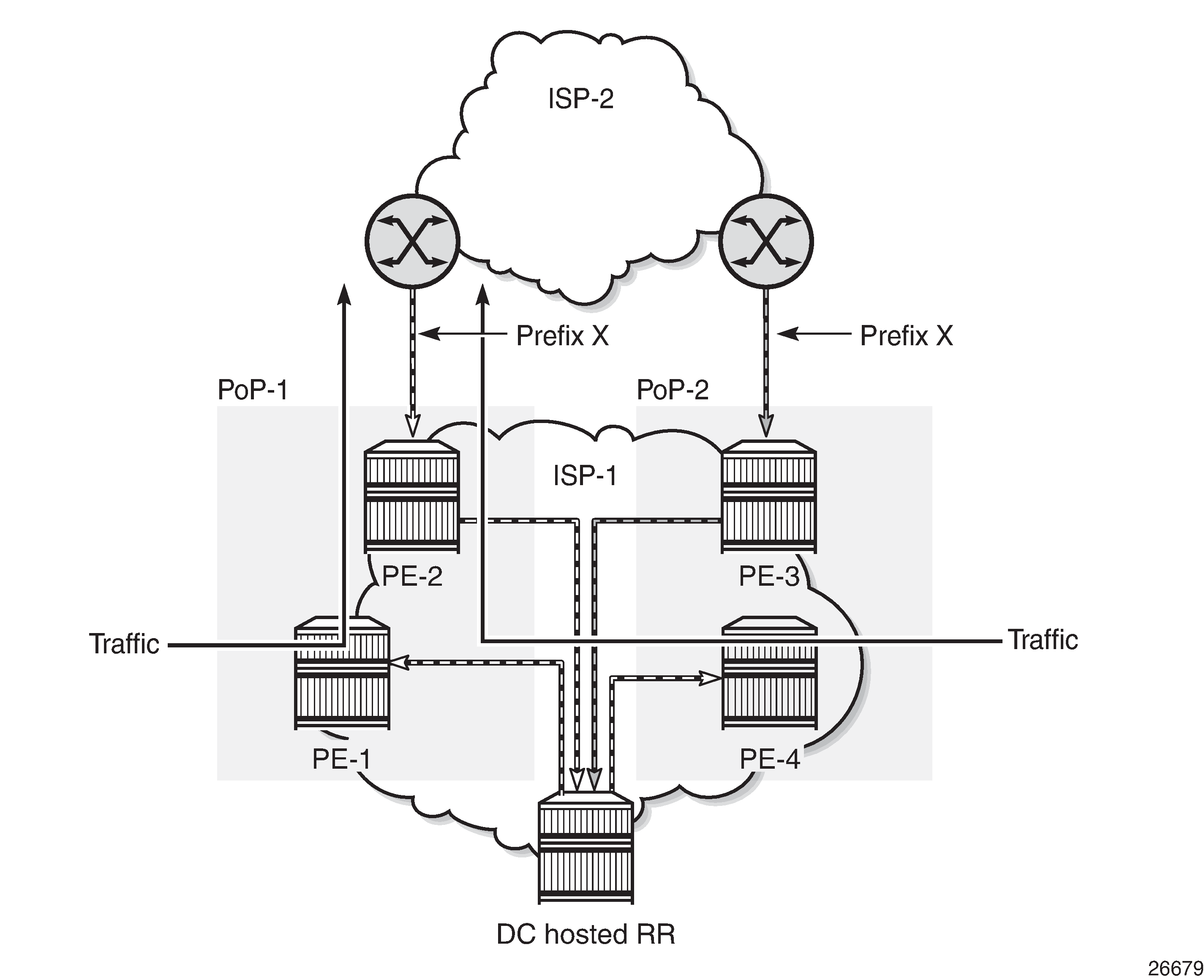
When a BGP route reflector receives multiple paths for the same IP destination, it normally selects and reflects a single best path in its routing domain to all clients in that domain, based on its own location in the domain. In Centralized route reflection, the centralized route reflector RR for ISP-1 is located in the datacenter (DC), and receives prefix X from ISP-2 through PE-2 in point of presence PoP-1 and also through PE-3 in PoP-2. RR selects and reflects PE-2 as the best path to the remaining route reflector clients because RR is closer to PoP-1 than it is to PoP-2, so the traffic to destination X flows as indicated. Therefore, sending traffic to another autonomous system (AS) through the closest possible exit point from the local AS, known as hot-potato routing, cannot be achieved.
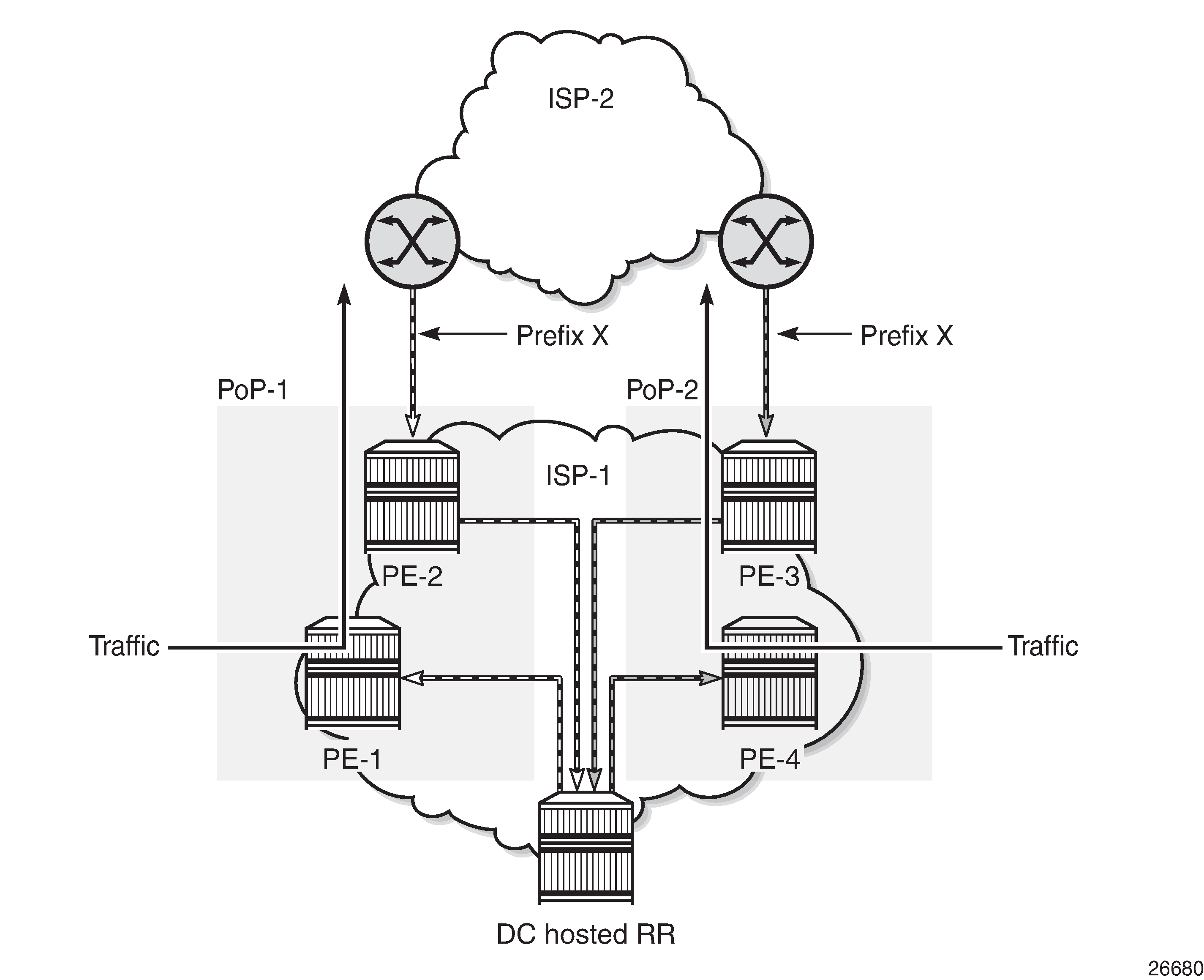
Hot-potato routing can be achieved using a route reflector selecting and reflecting multiple best paths, for different subdomains and from the point of view of a client in a subdomain, as outlined in RFC 9107 BGP optimal route reflection (ORR), and requires the route reflector to know the topology of each subdomain. In Centralized route reflection with ORR, the route reflector calculates the best path for PoP-1 and reflects that to the clients in PoP-1 (PE-1), and it also calculates the best path for PoP-2 and reflects that to the clients in PoP-2 (PE-4).
If the routing domain is non-hierarchical, the route reflector is part of the routing domain and thus has a view on the entire topology through the interior gateway protocol (IGP).
If the routing domain is hierarchical, the route reflector needs to extract the link state database (LSDB) from the subdomain it is not part of, which is achieved through BGP link state (BGP-LS). The use of BGP-LS allows the route reflector to learn the IGP topology information for OSPF areas and IS-IS levels in which the route reflector is not a direct participant. See the BGP Optimal Route Reflection for Hierarchical Networks chapter if the network topology is hierarchical.
ORR CLI commands
The BGP optimal-route-reflection context defines the shortest path first (SPF) parameters, and multiple locations.
*A:RR-5>config>router>bgp# optimal-route-reflection ?
  - optimal-route-reflection

      location        + Configure location ID for route reflector
 [no] spf-wait        - Configure the spf-wait parameters
The SPF calculation is configurable with the spf-wait command. Initial-wait and second-wait are optional arguments. These timers define when to initiate the first, second, and subsequent SPF runs after a topology change occurs.
*A:RR-5>config>router>bgp>orr# spf-wait ?
  - spf-wait <max-wait> [initial-wait <initial-wait>] [second-wait <second-wait>]

 <max-wait>           : [1..600] in seconds
 <initial-wait>       : [1..300] in seconds
 <second-wait>        : [1..300] in seconds
Multiple locations can be created in the optimal-route-reflection context, as follows. Each location is identified through a location ID [1..255], and contains a primary IP address and, optionally, a secondary IP address and a tertiary IP address, for redundancy reasons. These addresses must correspond to loopback or system IP addresses of routers participating in the IGP protocols, and are used as the starting point (or seed) for the SPF calculation. Because all clients in the same location receive the same optimal path for that location, these addresses must be close to the clients in that part of the network.
*A:RR-5>config>router>bgp>orr# location ?
  - location <location-id> [primary-ip-address <ipv4-address>] [secondary-ip-address <ipv4-address>]
    [tertiary-ip-address <ipv4-address>]

 <location-id>        : 1..255


 [no] primary-ip-add* - Configure Primary IP address for location ID
 [no] primary-ipv6-a* - Configure Primary IPv6 address for location ID
 [no] secondary-ip-a* - Configure Secondary IP address for location ID
 [no] secondary-ipv6* - Configure Secondary IPv6 address for location ID
 [no] tertiary-ip-ad* - Configure Tertiary IP address for location ID
 [no] tertiary-ipv6-* - Configure Tertiary IPv6 address for location ID
The locations are then referred to with the cluster command (residing in the BGP group context) through the orr-location argument, as follows.
*A:RR-5>config>router>bgp>group# cluster ?
  - cluster <cluster-id> orr-location <orr-location> [allow-local-fallback]
  - cluster <cluster-id>
  - no cluster

 <cluster-id>         : expressed in dotted decimal format (a.b.c.d)
 <orr-location>       : [1..255]
 <allow-local-fallb*> : configure to allow fallback on default orr location


*A:RR-5>config>router>bgp>group# neighbor 192.0.2.3 cluster ?
  - cluster <cluster-id> orr-location <orr-location> [allow-local-fallback]
  - cluster <cluster-id>
  - no cluster

 <cluster-id>         : expressed in dotted decimal format (a.b.c.d)
 <orr-location>       : [1..255]
 <allow-local-fallb*> : configure to allow fallback on default orr location
The location ID is referred to in the orr-location argument of the cluster command. Typically, the cluster command applies to a BGP peer group; all neighbors in that group share the same location ID, unless the cluster command applies at a neighbor level. The allow-local-fallback option allows the RR to advertise the best reachable BGP path using its own location, but only when no BGP routes are reachable for some location. Otherwise, no path would be advertised to the clients in that location.
Properties
The following properties apply to ORR in SR OS:
ORR is supported in the Base router BGP instance.
ORR is supported for the IPv4, label-IPv4, label-IPv6, VPN-IPv4, and VPN-IPv6 address families.
ORR is supported with add-paths, meaning that add-paths advertised to ORR clients are also ORR location-based.
Configuration
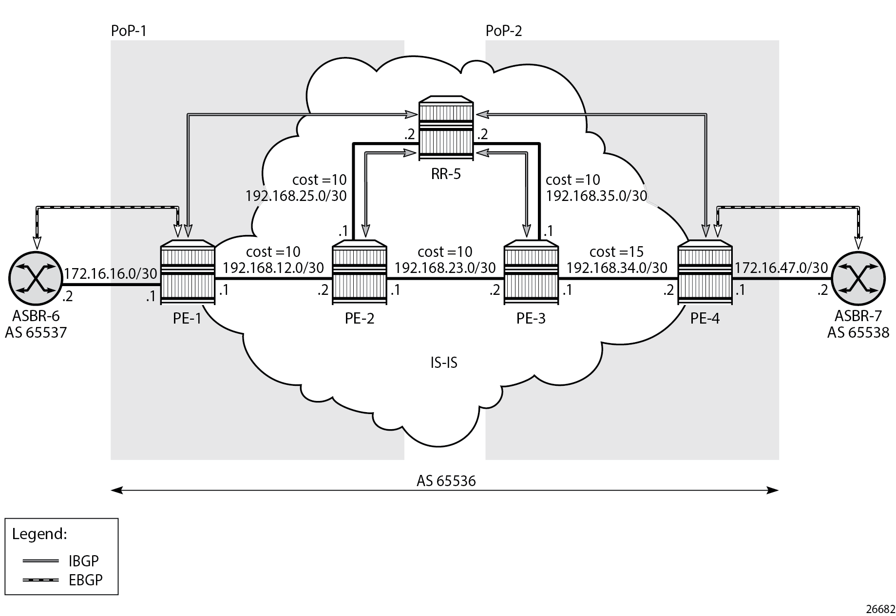
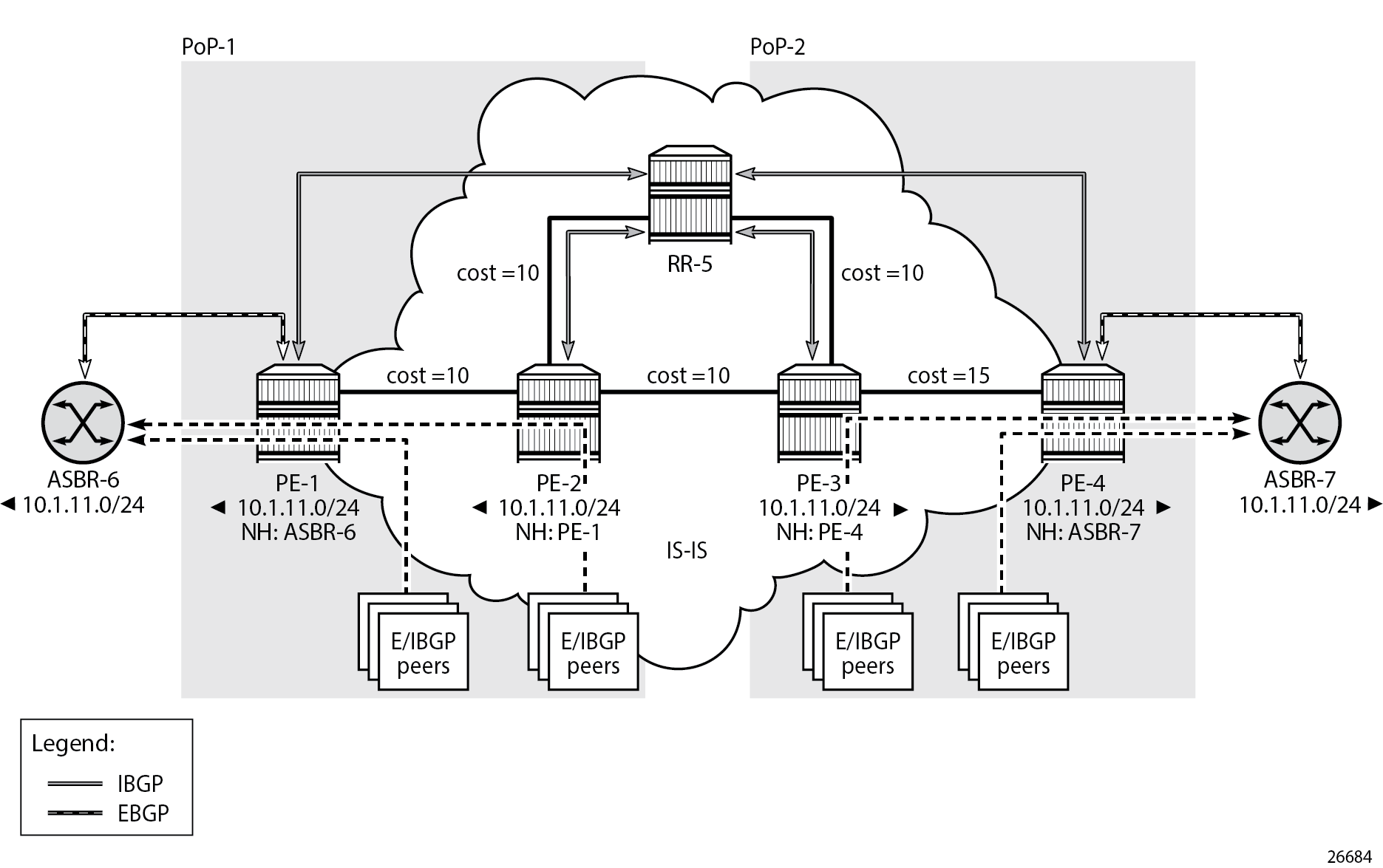
Example non-hierarchical networking using IS-IS shows the example topology. IS-IS is used as the IGP for AS 65536, with RR-5 taking the role of the route reflector for clients PE-1 to PE-4. Additionally, ASBR-6 in AS 65537 peers with PE-1, and ASBR-7 in AS 65538 peers with PE-4.
The initial configuration on all nodes includes:
Cards, MDAs, and ports
Router interfaces
IS-IS as IGP on all interfaces within AS 65536, in a non-hierarchical way (alternatively, OSPF can be used), and traffic engineering enabled
The basic IS-IS configuration is very similar for all routers, including the route reflector. The RR-5 configuration is as follows:
# on RR-5:
configure
    router Base
        isis 0
            area-id 49.0001
            traffic-engineering
            interface "system"
                no shutdown
            exit
            interface "int-RR-5-PE-2"
                interface-type point-to-point
                no shutdown
            exit
            interface "int-RR-5-PE-3"
                interface-type point-to-point
                no shutdown
            exit
            no shutdown
        exit
Route reflection without ORR
RR-5 peers with clients PE-1 to PE-4, and because RR-5 is the route reflector, the cluster command is added, defining the cluster ID attribute value to use. The configuration for RR-5 is as follows:
# on RR-5:
configure
    router Base
        autonomous-system 65536
        bgp
            loop-detect discard-route
            split-horizon
            group "IBGP"
                cluster 192.0.2.5
                peer-as 65536            # type internal
                neighbor 192.0.2.1
                exit
                neighbor 192.0.2.2
                exit
                neighbor 192.0.2.3
                exit
                neighbor 192.0.2.4
                exit
            exit
            no shutdown
        exit
PE-1 belongs to the cluster defined in the route reflector, so it does not need to be fully meshed with the other routers in the area; peering with the route reflectors in the area is sufficient for PE-1 to receive updates. Typically, two route reflectors are provisioned for redundancy, but that does not apply in this example. PE-1 also peers with ASBR-6 in AS 65537 through EBGP, so the PE-1 configuration is as follows:
# on PE-1:
configure
    router Base
        autonomous-system 65536
        bgp
            loop-detect discard-route
            split-horizon
            group "EBGP"
                neighbor 172.16.16.2
                    peer-as 65537
                exit
            exit
            group "IBGP"
                next-hop-self
                peer-as 65536
                neighbor 192.0.2.5
                exit
            exit
            no shutdown
        exit
PE-2 and PE-3 only peer with the route reflector. Their configuration is the same:
# on PE-2, PE-3:
configure
    router Base
        autonomous-system 65536
        bgp
            loop-detect discard-route
            split-horizon
            group "IBGP"
                peer-as 65536
                neighbor 192.0.2.5
                exit
            exit
            no shutdown
        exit
PE-4 also belongs to the cluster defined in the route reflector, but peers with ASBR-7 in AS 65538. The PE-4 configuration is similar to the configuration of PE-1.
Loopback address 10.1.11.1/24 is configured on ASBR-8 in AS 65540 (not shown in the example topology). ASBR-8 exports prefix 10.1.11.0/24 to its EBGP peers ASBR-6 in AS 65537 and ASBR-7 in AS 65538. ASBR-6 advertises prefix 10.1.11.0/24 to router PE-1; ASBR-7 advertises the same prefix to router PE-4.
RR-5 receives IBGP updates from PE-1 and PE-4, and selects the best path based on its own position in the topology. The IGP cost from RR-5 to PE-1 is 20, and the cost from RR-5 to PE-4 is 25, so RR-5 selects the BGP path with next hop 192.0.2.1.
*A:RR-5# show router bgp routes
===============================================================================
 BGP Router ID:192.0.2.5        AS:65536       Local AS:65536
===============================================================================
 Legend -
 Status codes  : u - used, s - suppressed, h - history, d - decayed, * - valid
                 l - leaked, x - stale, > - best, b - backup, p - purge
 Origin codes  : i - IGP, e - EGP, ? - incomplete

===============================================================================
BGP IPv4 Routes
===============================================================================
Flag  Network                                            LocalPref   MED
      Nexthop (Router)                                   Path-Id     IGP Cost
      As-Path                                                        Label
-------------------------------------------------------------------------------
u*>i  10.1.11.0/24                                       100         None
      192.0.2.1                                          None        20
      65537 65540                                                    -
*i    10.1.11.0/24                                       100         None
      192.0.2.4                                          None        25
      65538 65540                                                    -
-------------------------------------------------------------------------------
Routes : 2
===============================================================================
RR-5 reflects the path with next hop 192.0.2.1 to all clients except PE-1, because PE-1 is the client where the path was learned from).
For prefix 10.1.11.0/24, PE-1 received an EBGP route from ASBR-6 in AS 65537 with next hop 172.16.16.2 and no IBGP route from RR-5:
*A:PE-1# show router bgp routes
===============================================================================
 BGP Router ID:192.0.2.1        AS:65536       Local AS:65536
===============================================================================
 Legend -
 Status codes  : u - used, s - suppressed, h - history, d - decayed, * - valid
                 l - leaked, x - stale, > - best, b - backup, p - purge
 Origin codes  : i - IGP, e - EGP, ? - incomplete

===============================================================================
BGP IPv4 Routes
===============================================================================
Flag  Network                                            LocalPref   MED
      Nexthop (Router)                                   Path-Id     IGP Cost
      As-Path                                                        Label
-------------------------------------------------------------------------------
u*>i  10.1.11.0/24                                       None        None
      172.16.16.2                                        None        0
      65537 65540                                                    -
-------------------------------------------------------------------------------
Routes : 1
===============================================================================
As a result, traffic offered to PE-1 for destination 10.1.11.0/24 is routed to ASBR-6, as follows:
*A:PE-1# show router route-table protocol bgp

===============================================================================
Route Table (Router: Base)
===============================================================================
Dest Prefix[Flags]                            Type    Proto     Age        Pref
      Next Hop[Interface Name]                                    Metric
-------------------------------------------------------------------------------
10.1.11.0/24                                  Remote  BGP       00h01m33s  170
       172.16.16.2                                                  0
-------------------------------------------------------------------------------
No. of Routes: 1
Flags: n = Number of times nexthop is repeated
       B = BGP backup route available
       L = LFA nexthop available
       S = Sticky ECMP requested
===============================================================================
PE-2 received an IBGP route for prefix 10.1.11.0/24 with next hop 192.0.2.1 from RR-5:
*A:PE-2# show router bgp routes
===============================================================================
 BGP Router ID:192.0.2.2        AS:65536       Local AS:65536
===============================================================================
 Legend -
 Status codes  : u - used, s - suppressed, h - history, d - decayed, * - valid
                 l - leaked, x - stale, > - best, b - backup, p - purge
 Origin codes  : i - IGP, e - EGP, ? - incomplete

===============================================================================
BGP IPv4 Routes
===============================================================================
Flag  Network                                            LocalPref   MED
      Nexthop (Router)                                   Path-Id     IGP Cost
      As-Path                                                        Label
-------------------------------------------------------------------------------
u*>i  10.1.11.0/24                                       100         None
      192.0.2.1                                          None        10
      65537 65540                                                    -
-------------------------------------------------------------------------------
Routes : 1
===============================================================================
Traffic offered to PE-2 for destination 10.1.11.0/24 is routed to PE-1, as follows:
*A:PE-2# show router route-table protocol bgp

===============================================================================
Route Table (Router: Base)
===============================================================================
Dest Prefix[Flags]                            Type    Proto     Age        Pref
      Next Hop[Interface Name]                                    Metric
-------------------------------------------------------------------------------
10.1.11.0/24                                  Remote  BGP       00h00m40s  170
       192.168.12.1                                                 10
-------------------------------------------------------------------------------
No. of Routes: 1
Flags: n = Number of times nexthop is repeated
       B = BGP backup route available
       L = LFA nexthop available
       S = Sticky ECMP requested
===============================================================================
Likewise, PE-3 received an IBGP route for prefix 10.1.11.0/24 with next hop 192.0.2.1 from RR-5:
*A:PE-3# show router bgp routes
===============================================================================
 BGP Router ID:192.0.2.3        AS:65536       Local AS:65536
===============================================================================
 Legend -
 Status codes  : u - used, s - suppressed, h - history, d - decayed, * - valid
                 l - leaked, x - stale, > - best, b - backup, p - purge
 Origin codes  : i - IGP, e - EGP, ? - incomplete

===============================================================================
BGP IPv4 Routes
===============================================================================
Flag  Network                                            LocalPref   MED
      Nexthop (Router)                                   Path-Id     IGP Cost
      As-Path                                                        Label
-------------------------------------------------------------------------------
u*>i  10.1.11.0/24                                       100         None
      192.0.2.1                                          None        20
      65537 65540                                                    -
-------------------------------------------------------------------------------
Routes : 1
===============================================================================
Traffic offered to PE-3 for destination 10.1.11.0/24 is routed via the interface address 192.168.23.1 on PE-2, as follows:
*A:PE-3# show router route-table protocol bgp

===============================================================================
Route Table (Router: Base)
===============================================================================
Dest Prefix[Flags]                            Type    Proto     Age        Pref
      Next Hop[Interface Name]                                    Metric
-------------------------------------------------------------------------------
10.1.11.0/24                                  Remote  BGP       00h01m05s  170
       192.168.23.1                                                 20
-------------------------------------------------------------------------------
No. of Routes: 1
Flags: n = Number of times nexthop is repeated
       B = BGP backup route available
       L = LFA nexthop available
       S = Sticky ECMP requested
===============================================================================
For prefix 10.1.11.0/24, PE-4 received an EBGP route from ASBR-7 with next hop 172.16.47.2 and an IBGP route from RR-5 with next hop 192.0.2.1, as follows. EBGP routes are preferred over IBGP routes.
*A:PE-4# show router bgp routes
===============================================================================
 BGP Router ID:192.0.2.4        AS:65536       Local AS:65536
===============================================================================
 Legend -
 Status codes  : u - used, s - suppressed, h - history, d - decayed, * - valid
                 l - leaked, x - stale, > - best, b - backup, p - purge
 Origin codes  : i - IGP, e - EGP, ? - incomplete

===============================================================================
BGP IPv4 Routes
===============================================================================
Flag  Network                                            LocalPref   MED
      Nexthop (Router)                                   Path-Id     IGP Cost
      As-Path                                                        Label
-------------------------------------------------------------------------------
u*>i  10.1.11.0/24                                       None        None
      172.16.47.2                                        None        0
      65538 65540                                                    -
*i    10.1.11.0/24                                       100         None
      192.0.2.1                                          None        35
      65537 65540                                                    -
-------------------------------------------------------------------------------
Routes : 2
===============================================================================
The used route is the EBGP route from ASBR-7, so the traffic offered to PE-4 for destination 10.1.11.0/24 is routed to ASBR-7, as follows:
*A:PE-4# show router route-table protocol bgp

===============================================================================
Route Table (Router: Base)
===============================================================================
Dest Prefix[Flags]                            Type    Proto     Age        Pref
      Next Hop[Interface Name]                                    Metric
-------------------------------------------------------------------------------
10.1.11.0/24                                  Remote  BGP       00h01m54s  170
       172.16.47.2                                                  0
-------------------------------------------------------------------------------
No. of Routes: 1
Flags: n = Number of times nexthop is repeated
       B = BGP backup route available
       L = LFA nexthop available
       S = Sticky ECMP requested
===============================================================================
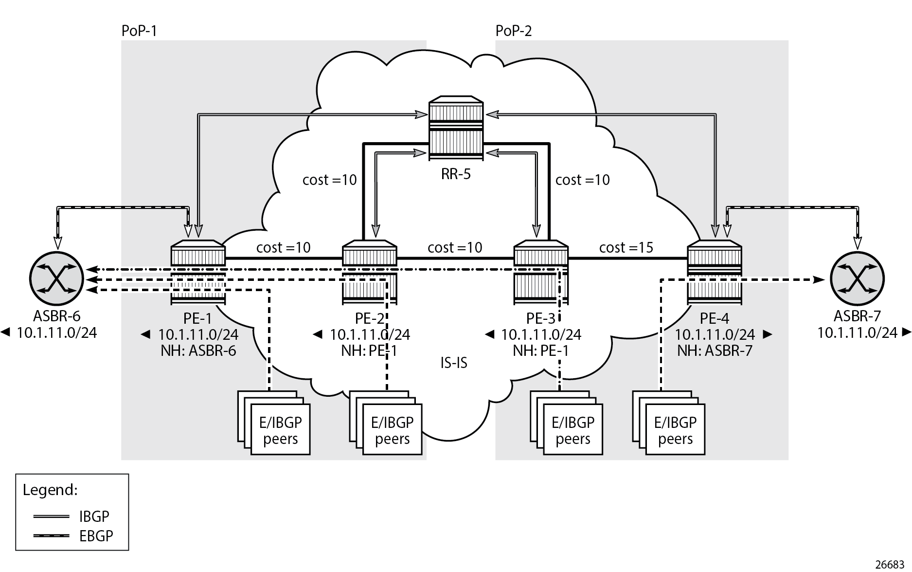
This is summarized in Suboptimal route reflection. Ultimately, PE-1 only has one path, and so do PE-2 and PE-3. PE-4 has two paths, but by default prefers the EBGP learned path over the IBGP learned path. The routing is suboptimal on PE-3, where the IGP cost to PE-1 is 20 and the IGP cost to PE-4 is 15.
Route reflection with ORR
For implementing ORR using the non-hierarchical topology from Suboptimal route reflection the route reflector RR-5 defines two locations in the optimal-route-reflection context. The primary IP address for location 1 is the PE-1 system IP address 192.0.2.1; the primary IP address for location 2 is loopback address 192.0.2.44 on PE-4 and the secondary IP address is loopback address 192.0.2.33 on PE-3. These addresses are used as the starting point for the SPF run. The ORR locations 1 and 2 are then referred to from within the group definitions through the cluster command. The overall BGP configuration of RR-5 is as follows:
# on RR-5
configure
    router Base
        autonomous-system 65536
        bgp
            loop-detect discard-route
            split-horizon
            optimal-route-reflection
                spf-wait 1 initial-wait 1 second-wait 1
                location 1
                    primary-ip-address 192.0.2.1
                exit
                location 2
                    primary-ip-address 192.0.2.44      # loopback address on PE-4
                    secondary-ip-address 192.0.2.33    # loopback address on PE-3
                exit
            exit
            group "IBGP-1"
                cluster 192.0.2.5 orr-location 1 allow-local-fallback
                peer-as 65536
                neighbor 192.0.2.1
                exit
                neighbor 192.0.2.2
                exit
            exit
            group "IBGP-2"
                cluster 192.0.2.5 orr-location 2 allow-local-fallback
                peer-as 65536
                neighbor 192.0.2.3
                exit
                neighbor 192.0.2.4
                exit
            exit
            no shutdown
        exit
No changes are required in the BGP clients.
ASBR-6 advertises prefix 10.1.11.0/24 to router PE-1; ASBR-7 advertises the same prefix to router PE-4. RR-5 receives the updates from PE-1 and PE-4, and now performs two SPF runs because two locations are used. The first SPF run uses the 192.0.2.1 address of PE-1 as the starting point for the first location, selects the path via PE-1 as the best path, and reflects that path to the remaining peers in the first location. The second SPF run uses the 192.0.2.44 loopback address of PE-4 as the starting point for the second location, selects the path via PE-4 as the best path, and reflects that path to the remaining peers in the second location.
In comparison with the previous scenario, there only is a change in the routing for this prefix on PE-3. RR-5 reflects the route with next hop 192.0.2.4 to PE-3.
*A:PE-3# show router bgp routes
===============================================================================
 BGP Router ID:192.0.2.3        AS:65536       Local AS:65536
===============================================================================
 Legend -
 Status codes  : u - used, s - suppressed, h - history, d - decayed, * - valid
                 l - leaked, x - stale, > - best, b - backup, p - purge
 Origin codes  : i - IGP, e - EGP, ? - incomplete

===============================================================================
BGP IPv4 Routes
===============================================================================
Flag  Network                                            LocalPref   MED
      Nexthop (Router)                                   Path-Id     IGP Cost
      As-Path                                                        Label
-------------------------------------------------------------------------------
u*>i  10.1.11.0/24                                       100         None
      192.0.2.4                                          None        15
      65538 65540                                                    -
-------------------------------------------------------------------------------
Routes : 1
===============================================================================
Traffic offered to PE-3 for destination 10.1.11.0/24 has next hop PE-4 and is routed via the interface address 192.168.34.2 on PE-4, as follows:
*A:PE-3# show router route-table protocol bgp

===============================================================================
Route Table (Router: Base)
===============================================================================
Dest Prefix[Flags]                            Type    Proto     Age        Pref
      Next Hop[Interface Name]                                    Metric
-------------------------------------------------------------------------------
10.1.11.0/24                                  Remote  BGP       00h03m12s  170
       192.168.34.2                                                 15
-------------------------------------------------------------------------------
No. of Routes: 1
Flags: n = Number of times nexthop is repeated
       B = BGP backup route available
       L = LFA nexthop available
       S = Sticky ECMP requested
===============================================================================
This is summarized in Optimal route reflection.
The following command provides the IGP distances for the configured reference points to all available BGP peers and all detected BGP next hops on the route reflector.
*A:RR-5# show router bgp optimal-route-reflection bgp-nh-info

===============================================================================
ORR BGP-NH Table (Router: Base)
===============================================================================
Location 1:
    Primary        : 192.0.2.1 [active]
    Secondary      : -
    Tertiary       : -
    Primary-ipv6   : -
    Secondary-ipv6 : -
    Tertiary-ipv6  : -
Location 2:
    Primary        : 192.0.2.44 [active]
    Secondary      : 192.0.2.33
    Tertiary       : -
    Primary-ipv6   : -
    Secondary-ipv6 : -
    Tertiary-ipv6  : -

Age          : 00h04m02s
Spf wait     : 1
Initial wait : 1
Second wait  : 1

-------------------------------------------------------------------------------
Next Hop
   Loc    Dest-Prefix
                               DB-Source  Type         Proto     Metric    Pref
-------------------------------------------------------------------------------

192.0.2.1
    1     192.0.2.1/32
                               IGP        Local        Local     0            0
    2     192.0.2.1/32
                               IGP        Remote       ISIS      35          15

192.0.2.4
    1     192.0.2.4/32
                               IGP        Remote       ISIS      35          15
    2     192.0.2.4/32
                               IGP        Local        Local     0            0
-------------------------------------------------------------------------------
No. of BGP-NHs: 2
===============================================================================
Conclusion
BGP optimal route reflection allows operators to optimize traffic streams through their network, even when the route reflector is placed out-of-path, for example in datacenters, thereby reducing the OPEX and CAPEX of route reflector deployment.