Flexible Algorithm for IS-IS
This chapter describes Flexible Algorithm for IS-IS.
Topics in this chapter include:
Applicability
The information and configuration in this chapter are based on SR OS Release 20.7.R1.
Overview
By default, an IGP-computed path is based on the shortest IGP metric, but frequently these paths are accompanied by traffic-engineered paths that are used to meet the requirements of the network. These traffic-engineered paths are facilitated by RSVP-TE or SR-TE, both of which perform source routing based on a set of metrics and constraints. In many networks this works well, but for some operators the overhead of traffic engineering in this manner is perceived as complex or costly.
Flexible Algorithm (or Flex-Algorithm) — as described in draft-ietf-lsr-flex-algo — provides a way for IGPs to compute constraint-based paths across a domain. Flex-Algorithm uses extensions to IS-IS and OSPF to advertise TLVs containing one or more Flexible Algorithm Definitions (FADs). Each FAD is associated with a numeric identifier and identifies a set of metrics and constraints to calculate the best path along the constrained topology.
When used with Segment Routing (SR), one or more Prefix Node-SIDs can be associated with a Flex-Algorithm identifier, thereby providing a level of traffic engineering without any associated control plane overhead or additional label stack imposition. The classic SPF technology used for shortest path calculation is referred to as algorithm 0. In SR OS Release 20.7.R1, up to five additional flexible algorithms can be supported.
This chapter provides an overview of the operation of Flex-Algorithm with IS-IS and how it is applicable to SR; specifically, SR-MPLS.
Flexible Algorithm Definition
A FAD is the construct that identifies how a path for a Flex-Algorithm will be computed, and consists of three components:
A calculation type
A metric type
A set of constraints, such as include or exclude statements
To guarantee loop-free forwarding for paths computed with a Flex-Algorithm, all routers that participate in that Flex-Algorithm must receive the definition of it. In IS-IS, the definition of the Flex-Algorithm is advertised using the FAD sub-TLV, which is a sub-TLV of the Router Capability TLV and has area scope, as shown in IS-IS FAD sub-TLV.
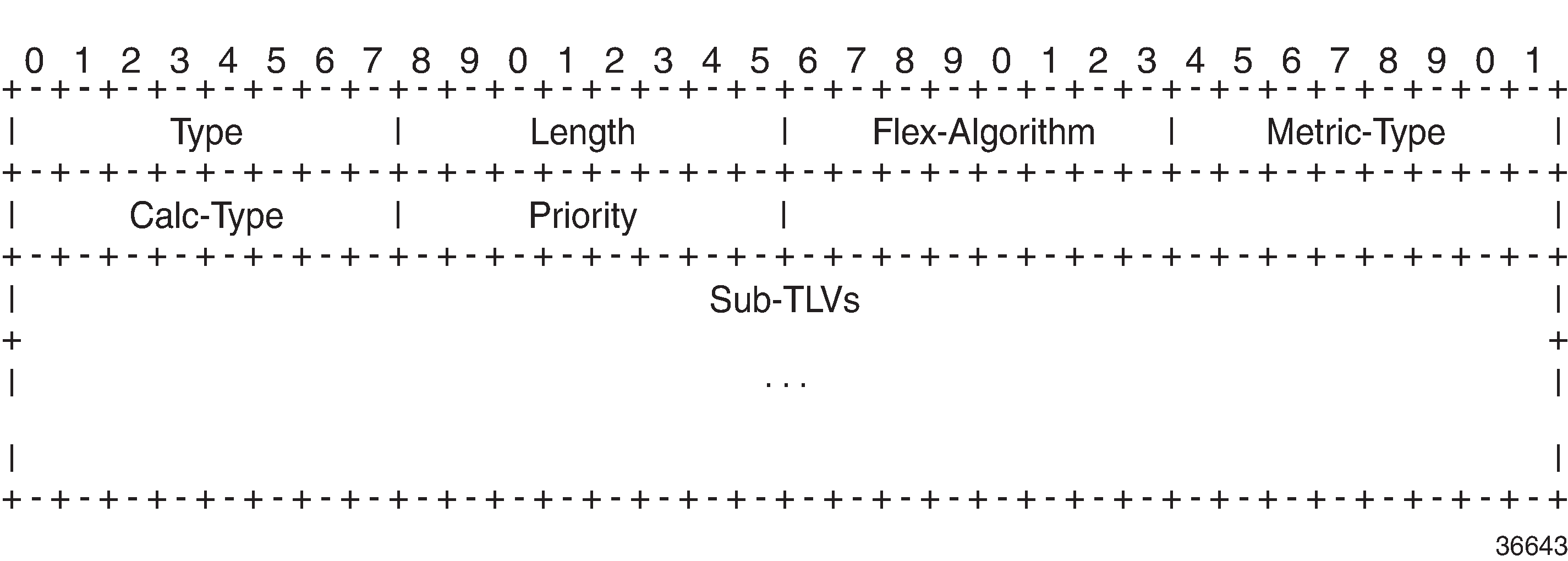
The Type and Length fields are self-explanatory. The Flex-Algorithm field contains a numeric identifier in the range 128 to 255 that is associated with the FAD through configuration. The Metric-Type field contains one of IGP metric (0), Min Unidirectional Link Delay (1), or TE Default Metric (2). The Calc-Type field contains a value from 0 to 127, identifying the IGP algorithm type, such as shortest path (0). One or more sub-TLV fields may be present to specify "colors" that are used to include or exclude links during the Flex-Algorithm path computation. These are encoded using Exclude Admin Group, Include-any Admin Group, Include-all Admin-Group, and Exclude SRLG sub-TLVs.
The Sub-TLV field may also contain a Flags sub-TLV. In draft-ietf-lsr-flex-algo, only the M-flag (Prefix Metric) is defined. The M-flag indicates that the Flex-Algorithm Prefix Metric (FAPM) sub-TLV must be advertised with the prefix. The FAPM is not a sub-TLV of the FAD, but rather a sub-TLV of the Extended IP Reachability TLV, and is intended to assist with inter-area and inter-domain Flex-Algorithm path calculations.
Any IGP shortest-path tree calculation is limited to a single area, and the same applies to Flex-Algorithm. To allow for inter-area or inter-domain Flex-Algorithm calculations, the FAPM sub-TLV can be attached to Extended IP Reachability TLVs that are advertised between areas or domains. The FAPM sub-TLV contains the metric equivalent to the metric of the redistributing router to reach the prefix. If the FAD Flags sub-TLV has the M-flag set, the FAPM must be used when calculating prefix reachability for inter-area and inter-domain prefixes.
Only a subset of the routers participating in each Flex-Algorithm need to advertise the definition of the Flex-Algorithm. However, every router that is part of the intended Flex-Algorithm topology must be configured to participate in the Flex-Algorithm. If a router is not configured to participate in a specific Flex-Algorithm, it ignores FAD sub-TLV advertisements for that Flex-Algorithm.
Application-specific link attributes
Advertisement of link attributes for the purpose of traffic engineering was initially introduced by RFC 5305, which included a number of sub-TLVs encoded within the Extended IS Reachability TLV, such as admin group, TE default metric, maximum link bandwidth, and unreserved bandwidth.
RFC 7308 updated RFC 5305 by increasing the size of the admin group sub-TLV, thereby allowing for advertisement of more than the standard 32 admin groups per link. RFC 5305 was again updated by RFC 8570, which proposed the use of metric extensions, adding additional sub-TLVs to the Enhanced IS Reachability TLV, such as unidirectional link delay, unidirectional link loss, and unidirectional available bandwidth. These traffic-engineering extensions have been widely deployed for RSVP-TE purposes.
Other applications that also make use of traffic-engineering link attributes have been defined, such as SR, Loopfree Alternates (LFAs), and Flex-Algorithm. If these applications coexist, it may be advisable to unambiguously indicate which traffic-engineering attributes apply to which application. Their requirements may differ on a link-to-link basis, or two applications may not be fully congruent; for example, SR may not be fully deployed network-wide. For these reasons, Flex-Algorithm specifies the use of Application-Specific Link Attributes (ASLAs), from draft-ietf-isis-te-app, which defines two new code points for IS-IS ASLA advertisements:
ASLA sub-TLV for Extended IS Reachability and Neighbor Link Attributes TLVs (TLVs 22, 23, 25, 141, 222, and 223)
Application-Specific Shared Risk Link Group (SRLG) TLV
The ASLA sub-TLV contains Link Attribute sub-sub-TLVs, the format of which matches the existing formats defined in RFC 5305, RFC 7308, and RFC 8570. The Application-Specific SRLG TLV encodes link identifier sub-TLVs, such as IPv4/IPv6 Interface address, IPv4/IPv6 Neighbor address, and Link Local/Remote Identifiers. SR OS will advertise Application-Specific SRLG TLVs, but does not use SRLG TLVs for computing SRLG-diverse paths in Release 20.7.R1. Support for LFA (primary/backup) SRLG diversity for Flex-Algorithm is provided using locally configured LFA policies.
Each of the ASLA sub-TLV and Application-Specific SRLG TLV advertisements are coupled with an Application Identifier Bit Mask that identifies the applications associated with an advertisement. Two bit masks are available for use:
the Standard Applications Bit Mask (SABM)is used for applications, where the definition of each bit is controlled by IANA.
the User-Defined Applications Bit Mask (UDABM) allows for future non-standard extensibility.
The encoding shown in Application Identifier Bit Mask is used by both the ASLA sub-TLV and the Application-Specific SRLG TLV.
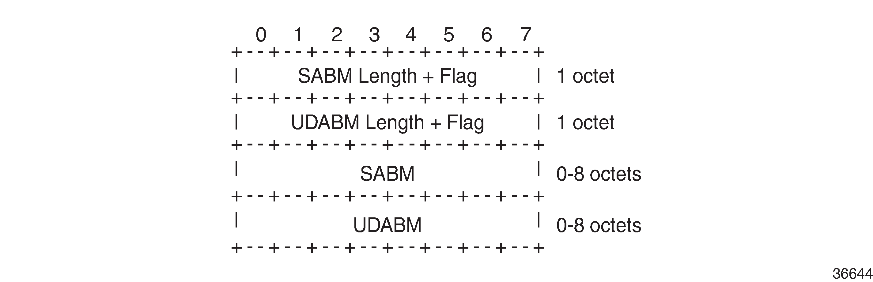
The SABM Length + Flag field contains a single L-flag, known as the "Legacy" flag. When the L-flag is set in the Application Identifier Bit Mask, all the applications specified in the bit mask must use the legacy traffic-engineering advertisements for the corresponding link. That is, link attributes should be carried as sub-TLVs of the Extended IS Reachability TLV rather than sub-sub-TLVs of the ASLA sub-TLV. This allows for a level of backward compatibility such that legacy advertisements may continue to be used if:
Only RSVP-TE is deployed
Only SR /LFA is deployed
A combination of RSVP-TE and SR/LFA is deployed, but the set of links that each application uses are fully congruent.
The UDABM Length + Flag field contains a single R-flag, which is reserved for future use.
The SABM field defines four bits to identify applications:
The R-bit (bit 0) specifies RSVP-TE
The S-bit (bit 1) specifies SR
The F-Bit (bit 2) specifies LFA
The X-bit (bit 3) specifies Flex-Algorithm
Applicability of Flex-Algorithm to SR
A router may use various algorithms when calculating reachability to other nodes or prefixes attached to those nodes. RFC 8667, IS-IS extensions for SR, describes the use of the SR-Algorithm sub-TLV (carried as part of the Router Capabilities TLV) to advertise the algorithms that the router can support. By default, an SR router will signal support for algorithm 0 (metric-based SPF). To advertise participation for a specific Flex-Algorithm for SR, the Flex-Algorithm value must also be advertised in the SR-Algorithm sub-TLV.
When an SR router advertises a Prefix SID, it includes an SR-algorithm, so it is possible to associate a Prefix SID with a specific algorithm. For example, a router may advertise prefix P1 with Prefix SID {index=1, algorithm=0} and prefix P2 with Prefix SID {index=2, algorithm=128}. This indicates to other SR routers that to reach prefix P1, the default metric-based SPF should be used to calculate the best path, and to reach prefix P2, Flex-Algorithm 128 (and whatever that algorithm dictates) should be used.
Equally, in an SR-MPLS environment with an SR Global Block (SRGB) of {1000-1999}, a router may advertise prefix P1 with Prefix SID {index=1, algorithm=0}, and also Prefix SID {index=101, algorithm=129}. This indicates to other SR routers that when label 1001 is the active label to reach prefix P1, the default metric-based SPF should be used to calculate the best path, and when label 1101 is the active label, Flex-Algorithm 129 should be used.
Flexible Algorithm example in an SR-MPLS domain shows an SR-MPLS domain where all links have metric 10 except for links PE-5-PE-4 and PE-4-PE-3, which both have metric 30. All links have a unidirectional link latency of 10 ms, except for links PE-5-PE-4 and PE-4-PE-3, which both have a unidirectional latency of 5 ms. All routers use an SRGB of {1000-1999}.
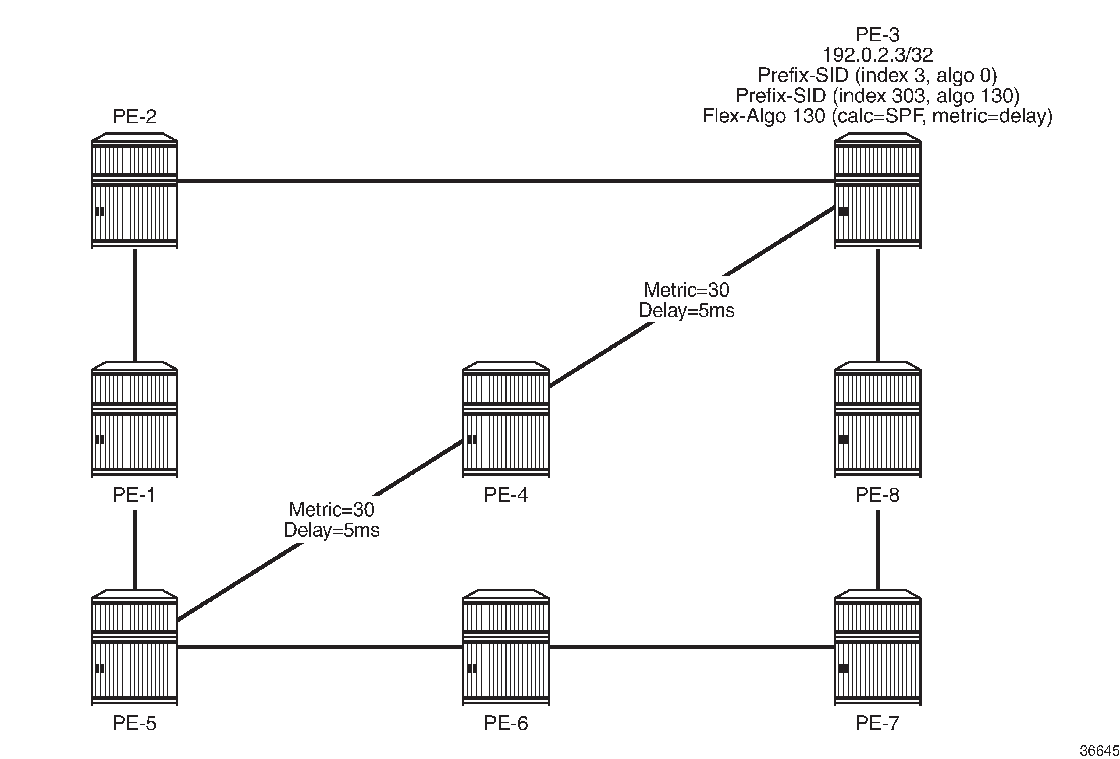
In addition to the default algorithm 0 (metric-based SPF), all routers participate in Flex-Algorithm 130 with FAD {calc-type=SPF, metric=delay, constraints=none}. Router PE-3 advertises prefix 192.0.2.3/32 with Prefix SID {index=3, algorithm=0} and Prefix SID {index=303, algorithm=130}. Router PE-5 has an SR-TE LSP provisioned with a destination of PE-3 (192.0.2.3) and a top (active) label of 1003. As a result, it is associated with algorithm 0 and uses the shortest path IGP metric PE-5-PE-1-PE-2-PE-3 to reach its destination. Router PE-5 is also provisioned with a second SR-TE LSP, again with a destination of PE-3 (192.0.2.3), but this time with a top (active) label of 1303. This second LSP is associated with Flex-Algorithm 130 and uses the shortest path delay metric PE-5-PE-4-PE-3 to reach its destination.
Example topology
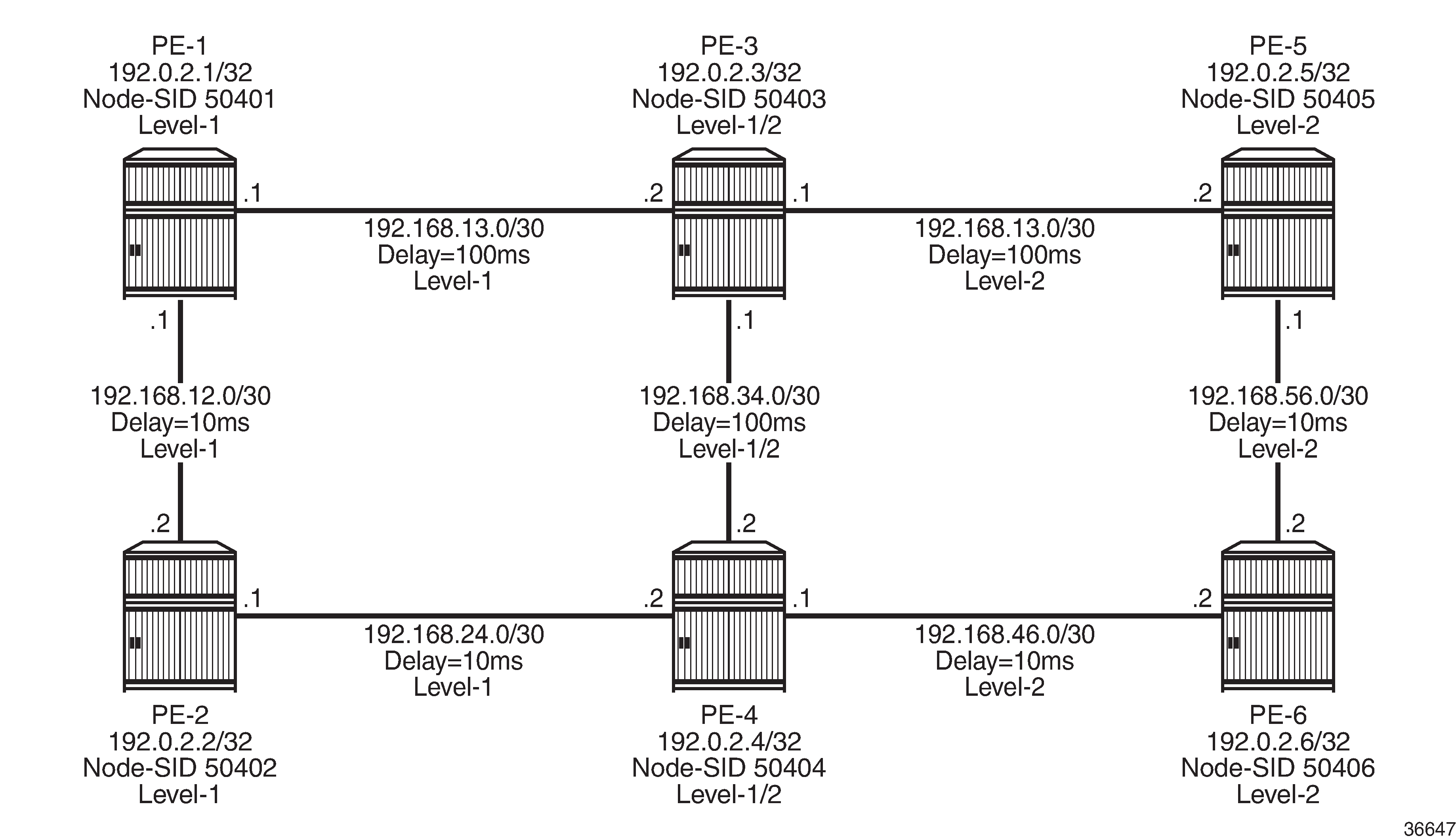
Example topology shows the example topology used in this chapter. All routers within the example topology form part of Autonomous System 64496 and belong to the same IS-IS Level-2 area. All IGP link metrics are 100 and are symmetric. Unidirectional link delay is also configured, and all links have a delay of 10 ms, with the exception of links PE-1-PE-3, PE-3-PE-5, and PE-3-PE-4, which have a delay of 100 ms. SR is enabled within the domain, and the associated Node-SIDs used as a baseline are shown (Adj-SIDs are not shown for the purpose of clarity). The SRGB in use is {50000-54999}.
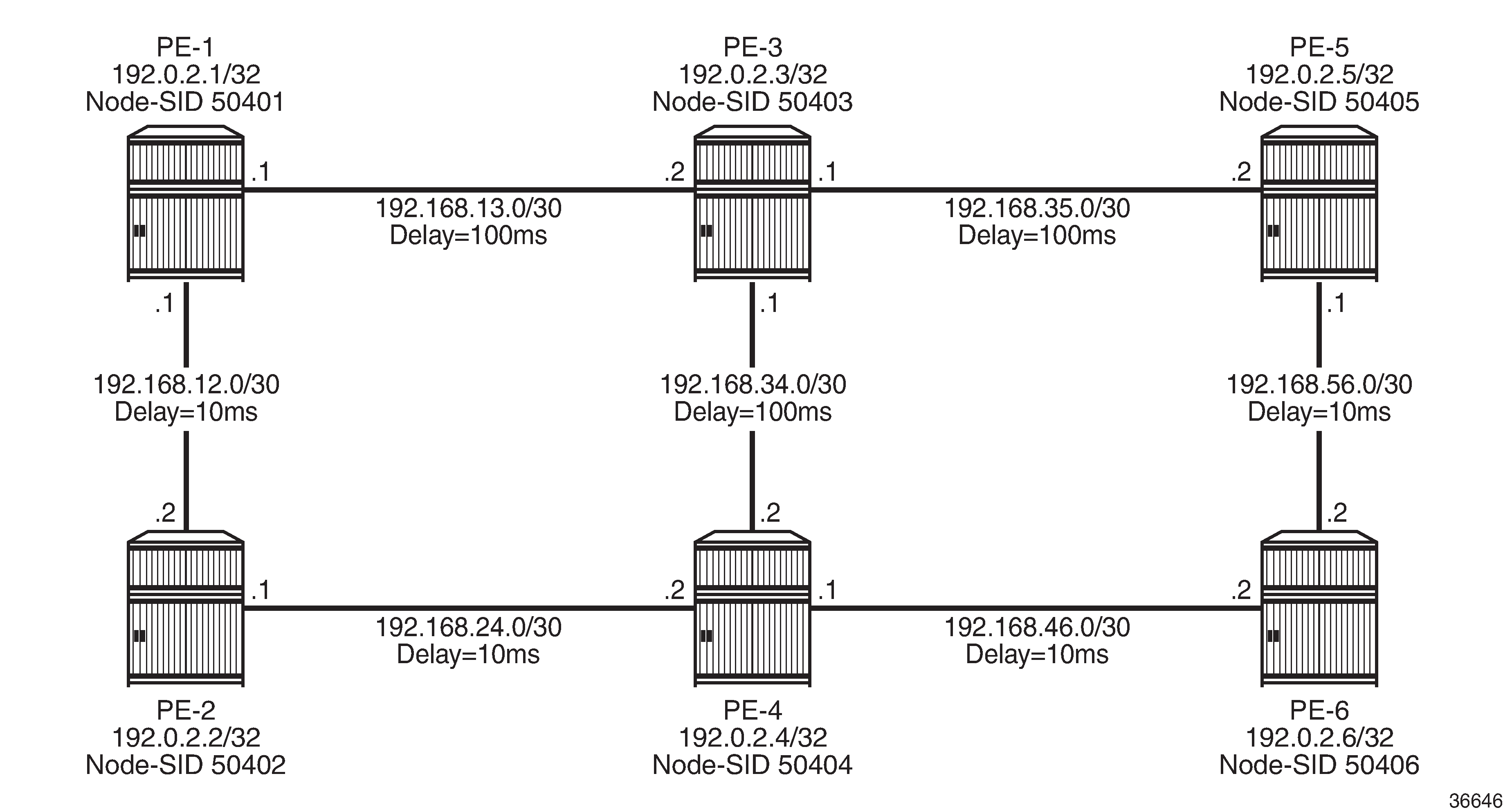
An additional step is required if a Flex-Algorithm uses a metric-type of delay. Before the delay metric can be advertised, a value for that metric needs to be derived. There are various methods available to do this (including OAM probes and so on), but currently the only method that SR OS supports is static configuration. The following output provides an example of static configuration of delay metric at PE-1. The delay is entered as an if-attribute under each interface and is expressed in microseconds. As per Example topology, the link PE-1-PE-2 has a delay metric of 10 ms, while the link PE-1-PE-3 has a delay metric of 100 ms.
# on PE-1:
configure
    router Base
        interface "int-PE-1-PE-2"
            if-attribute
                delay
                    static 10000
                exit
            exit
            no shutdown
        exit
        interface "int-PE-1-PE-3"
            if-attribute
                delay
                    static 100000
                exit
            exit
            no shutdown
        exit
Configuration
The following steps are required to configure and enable the use of Flex-Algorithm:
Enable the use of ASLAs
Configure and advertise the FAD
Configure Flex-Algorithm participation
Configure a Flex-Algorithm Prefix Node-SID
Configure traffic steering using Flex-Algorithm
These steps are described in the following subsections.
Enable the use of ASLAs
Flex-Algorithm specifies the use of ASLAs for advertisement of traffic-engineering information. If not already enabled, enable these under the IS-IS context for all routers in the domain, as follows:
# on all PEs:
configure
    router Base
        isis 0
            traffic-engineering-options
                application-link-attributes
                exit
            exit
For backward compatibility, the application-link-attributes command has an optional legacy argument, which allows link attributes to be encoded in the legacy manner as sub-TLVs of the Extended IS Reachability TLV, rather than being encoded as (sub-)sub-TLVs of the ASLA sub-TLV.
The following output shows how ASLAs are advertised as sub-TLVs of the Extended IS Reachability TLV. The output is taken at PE-1 and is truncated to include only the IS neighbor PE-3. Within the Extended IS Reachability TLV, there are three ASLA sub-TLVs:
The first is non-legacy (L-bit is not set) and has an SABM field that has the R-bit and S-bit set, indicating that these attributes are specific to RSVP-TE and SR, respectively. The link attributes include Max Link Bandwidth and TE Metric.
The second is non-legacy and has an SABM field with R-bit set, indicating that the intended application is RSVP-TE, and contains reservable and unreserved bandwidth link attributes.
The third ASLA sub-TLV is non-legacy and has the X-bit set, indicating that this is specific only to Flex-Algorithm. This sub-TLV contains the Delay and TE Metric link attributes.
*A:PE-1# show router isis database detail PE-1.00-00

===============================================================================
Rtr Base ISIS Instance 0 Database (detail)
===============================================================================

Displaying Level 2 database
-------------------------------------------------------------------------------
LSP ID    : PE-1.00-00                                  Level     : L2
Sequence  : 0x114                  Checksum  : 0xe884   Lifetime  : 38293
Version   : 1                      Pkt Type  : 20       Pkt Ver   : 1
Attributes: L1L2                   Max Area  : 3        Alloc Len : 1492
SYS ID    : 1920.0000.2001         SysID Len : 6        Used Len  : 607
  ---snip---
  TE IS Nbrs   :
    Nbr   : PE-3.00
    Default Metric  : 100
    Sub TLV Len     : 103
    IF Addr   : 192.168.13.1
    Nbr IP    : 192.168.13.2
    TE APP LINK ATTR    :
      SABML-flag:Non-Legacy SABM-flags:R S
        MaxLink BW: 10000000 kbps
        TE Metric : 100
    TE APP LINK ATTR    :
      SABML-flag:Non-Legacy SABM-flags:R
        Resvble BW: 10000000 kbps
        Unresvd BW:
            BW[0] : 10000000 kbps
            BW[1] : 10000000 kbps
            BW[2] : 10000000 kbps
            BW[3] : 10000000 kbps
            BW[4] : 10000000 kbps
            BW[5] : 10000000 kbps
            BW[6] : 10000000 kbps
            BW[7] : 10000000 kbps
    TE APP LINK ATTR    :
      SABML-flag:Non-Legacy SABM-flags:   X
        Delay     : 100000
        TE Metric : 100
    Adj-SID: Flags:v4VLP Weight:0 Label:150013
    Adj-SID: Flags:v6VL Weight:0 Label:524272
  ---snip---
Configure FAD and participation
To define the FAD, the following example uses a metric-type of delay with no other constraints. As previously described, not all participating routers need to advertise the FAD; only their participation in it. Therefore, in this example, PE-1 and PE-5 are used to advertise the FAD and the following configuration is applied to both routers.
First, the FAD is created with a name under the flexible-algorithm-definitions context. After the flex-algo context has been created, the metric-type (IGP, TE metric, delay) and any other constraints (include-all, include-any, exclude) can be configured within it. It is also possible to configure a priority value for the flex-algo in the range 0 to 255. If multiple FAD advertisements are received, the highest priority will be selected. If priorities are equal, the FAD advertised by the highest router ID is selected. The default priority is 100.
# on PE-1, PE-5:
configure
    router Base
        flexible-algorithm-definitions
            flex-algo "FlexAlgo-128" create
                description "FlexAlgo-128-Delay-Metric"
                metric-type delay
                no shutdown
            exit
        exit
After the FAD has been defined, it can be advertised into IS-IS. This is done under the flexible-algorithms context within the IS-IS instance. The Flex-Algorithm must initially be assigned a numeric identifier in the range 128 to 255, after which the advertise command is used to advertise the previously configured FAD "FlexAlgo-128". The participate command is used to configure participation for the specific Flex-Algorithm and must be enabled on all routers that are part of this Flex-Algorithm topology. Finally, LFA may be enabled. If it is, the LFA SPF will use the same Flex-Algorithm topology as that used to calculate the primary path. Also, LFA settings (such as TI-LFA, Remote-LFA) within a Flex-Algorithm are inherited from the base IS-IS/LFA configuration.
PE-1 and PE-5 both advertise and participate in the Flex-Algorithm, as follows:
# on PE-1, PE-5:
configure
    router Base
        isis 0
            flexible-algorithms
                flex-algo 128
                    advertise "FlexAlgo-128"
                    participate
                    loopfree-alternates
                    exit
                exit
                no shutdown
            exit
        exit
What remains is to configure all other routers in the domain to participate in the same Flex-Algorithm, as in the following output. This is essentially the same configuration as applied to PE-1 and PE-5, with the exception of the advertise statement.
# on PE-2, PE-3, PE-4, PE-6:
configure
    router Base
        isis 0
            flexible-algorithms
                flex-algo 128
                    participate
                    loopfree-alternates
                    exit
                exit
                no shutdown
            exit
        exit
After the FAD with Flex-Algorithm identifier 128 has been advertised and all routers have signaled that they participate in this Flex-Algorithm, it can be validated with router outputs. The following output shows the relevant parts of the IS-IS LSP advertised by PE-1. Within the Router Capabilities TLV, there are two notable additions. The SR-Algorithm sub-TLV shows the default metric-based SPF (algorithm 0), but now includes algorithm 128, showing its participation in this algorithm. There is also a FAD sub-TLV containing the definition of Flex-Algorithm 128 with metric-type of delay. The FAD has a Flags sub-TLV with the M-flag set, indicating that the FAPM must be used when calculating prefix reachability for inter-area and inter-domain prefixes.
*A:PE-1# show router isis database PE-1.00-00 detail

===============================================================================
Rtr Base ISIS Instance 0 Database (detail)
===============================================================================

Displaying Level 2 database
-------------------------------------------------------------------------------
LSP ID    : PE-1.00-00                                  Level     : L2
Sequence  : 0x114                  Checksum  : 0xe884   Lifetime  : 49976
Version   : 1                      Pkt Type  : 20       Pkt Ver   : 1
Attributes: L1L2                   Max Area  : 3        Alloc Len : 1492
SYS ID    : 1920.0000.2001         SysID Len : 6        Used Len  : 607

   ---snip---
  Router Cap : 192.0.2.1, D:0, S:0
    TE Node Cap : B E M  P
    SR Cap: IPv4 MPLS-IPv6
       SRGB Base:50000, Range:5000
    SR Alg: metric based SPF, 128
    Node MSD Cap: BMI : 12 ERLD : 15
    FAD Sub-Tlv:
        Flex-Algorithm   : 128
        Metric-Type      : delay
        Calculation-Type : 0
        Priority         : 100
        Flags: M
   ---snip---
Configure a Flex-Algorithm Prefix Node-SID
At each egress node, a Prefix Node-SID must be assigned to each Flex-Algorithm in use. This will be advertised as a Prefix SID sub-TLV that will contain (among other things) the algorithm to be used to reach the associated Prefix Node-SID. The Node-SID is taken from the generic SRGB; no special or dedicated label space is required. In the following example, PE-5 is the egress router and the relevant configuration is shown in the following output. Under the IS-IS system interface context, the Node-SID label assigned to algorithm 0 is 50405 and is generic SR configuration. Within the same context, a sub-context is created for flex-algo 128 for which a Prefix SID label of 54405 is assigned.
# on PE-5:
configure
    router Base
        isis 0
            interface "system"
                ipv4-node-sid label 50405
                passive
                flex-algo 128
                    ipv4-node-sid label 54405
                exit
                no shutdown
            exit
        exit
When configured, the additional Prefix SID advertisement can be viewed in the PE-5 advertised IS-IS LSP.
*A:PE-5# show router isis database PE-5.00-00 detail

===============================================================================
Rtr Base ISIS Instance 0 Database (detail)
===============================================================================

Displaying Level 2 database
-------------------------------------------------------------------------------
LSP ID    : PE-5.00-00                                  Level     : L2
Sequence  : 0x101                  Checksum  : 0x9c1c   Lifetime  : 53986
Version   : 1                      Pkt Type  : 20       Pkt Ver   : 1
Attributes: L1L2                   Max Area  : 3        Alloc Len : 1492
SYS ID    : 1920.0000.2005         SysID Len : 6        Used Len  : 650
  ---snip---
    TE IP Reach   :
    Default Metric  : 0
    Control Info:   S, prefLen 32
    Prefix   : 192.0.2.5
    Sub TLV   :
      Prefix-SID Index:405, Algo:0, Flags:NnP
      Prefix-SID Index:4405, Algo:128, Flags:NnP
  ---snip---
The Flex-Algorithm Prefix SID can also be viewed using the show router prefix-sids command with the relevant flex-algo extension. The index is 4405 and with an SRGB start-label of 50000, this equates to the configured label value of 54405.
*A:PE-1# show router isis prefix-sids algo 128

===============================================================================
Rtr Base ISIS Instance 0 Prefix/SID Table
===============================================================================
Prefix                            SID        Lvl/Typ    SRMS   AdvRtr
                                              Algo       MT     Flags
-------------------------------------------------------------------------------
192.0.2.5/32                      4405       2/Int.      N     PE-5
                                                 128        0      NnP
-------------------------------------------------------------------------------
No. of Prefix/SIDs:  (1 unique)
-------------------------------------------------------------------------------
SRMS : Y/N  = prefix SID advertised by SR Mapping Server (Y) or not (N)
       S    = SRMS prefix SID is selected to be programmed
Flags: R    = Re-advertisement
       N    = Node-SID
       nP   = no penultimate hop POP
       E    = Explicit-Null
       V    = Prefix-SID carries a value
       L    = value/index has local significance
===============================================================================
After the Prefix Node-SID has been correctly advertised by PE-5 with algorithm 128, it is possible to use the tunnel table to verify the Flex-Algorithm path toward the destination prefix. The following output shows the tunnel table at PE-1 for PE-5 (192.0.2.5/32). In this output, there are two entries. The first entry (tunnel ID 524296) is the default SR-ISIS tunnel calculated using algorithm 0. This has a next-hop of PE-3 (192.168.13.2) and metric of 200 representing the IGP cost of the path PE-1-PE-3-PE-5. The second entry (tunnel ID 524198) is calculated using Flex-Algorithm 128. It has a next-hop of PE-2 (192.168.12.2) and a metric of 40000 representing the accumulative delay metric (40msec) for the path PE-1-PE-2-PE-4-PE-6-PE-5.
*A:PE-1# show router tunnel-table 192.0.2.5/32 protocol isis

===============================================================================
IPv4 Tunnel Table (Router: Base)
===============================================================================
Destination           Owner     Encap TunnelId  Pref   Nexthop        Metric
   Color
-------------------------------------------------------------------------------
192.0.2.5/32 [L]      isis (0)  MPLS  524296    11     192.168.13.2   200
192.0.2.5/32 [L]      isis (0)  MPLS  524298    11     192.168.12.2   40000
-------------------------------------------------------------------------------
Flags: B = BGP or MPLS backup hop available
       L = Loop-Free Alternate (LFA) hop available
       E = Inactive best-external BGP route
       k = RIB-API or Forwarding Policy backup hop
===============================================================================
Traffic steering using Flex-Algorithm
To statically steer traffic into a Flex-Algorithm LSP, the static-route-entry allows for indirect next-hops to configure a Flex-Algorithm identifier in addition to a resolution-filter specifying SR-ISIS. This uses the specified Flex-Algorithm to construct a tunnel toward the indirect next-hop. In the following example, a static-route for prefix 172.16.0.1/32 is configured at PE-1 toward PE-5 (192.0.2.5) using a resolution-filter of SR-ISIS and flex-algo 128. Note that if no tunnel exists in the tunnel table for the referenced Flex-Algorithm identifier that the static-route will not become active.
# on PE-1:
configure
    router Base
        static-route-entry 172.16.0.1/32
            indirect 192.0.2.5
                tunnel-next-hop
                    resolution-filter
                        sr-isis
                    exit
                    flex-algo 128
                    resolution filter
                exit
                no shutdown
            exit
        exit
From the prefix in the route-table, the next-hop is PE-5 (192.0.2.5) and the next-hop is resolved to an SR-ISIS tunnel with tunnel ID 524298, which is the tunnel ID of the Flex-Algorithm LSP.
*A:PE-1# show router route-table 172.16.0.1/32

===============================================================================
Route Table (Router: Base)
===============================================================================
Dest Prefix[Flags]                            Type    Proto     Age        Pref
      Next Hop[Interface Name]                                    Metric
-------------------------------------------------------------------------------
172.16.0.1/32                                 Remote  Static    01h29m00s  5
       192.0.2.5 (tunneled:SR-ISIS:524298)                          1
-------------------------------------------------------------------------------
No. of Routes: 1
Flags: n = Number of times nexthop is repeated
       B = BGP backup route available
       L = LFA nexthop available
       S = Sticky ECMP requested
===============================================================================
Flex-Algorithm LSPs can also be used for BGP next-hop resolution and/or service next-hop resolution wherever an SR-TE or SR Policy path contains one or more Prefix Node-SIDs and the auto-bind-tunnel resolution-filter is configured appropriately. The following output provides an example of an SR-TE LSP configured at PE-1 toward PE-5. The LSP references a primary path named "FlexAlgo-128", where that path has a single hop containing the label 54405. This is the label value that was previously allocated to Flex-Algorithm 128 at PE-5.
# on PE-1:
configure
    router Base
        mpls
            path "FlexAlgo-128"
                hop 1 sid-label 54405
                no shutdown
            exit
            lsp "PE-1-PE-5-SR-TE-FlexAlgo128" sr-te
                to 192.0.2.5
                max-sr-labels 1 additional-frr-labels 2
                primary "FlexAlgo-128"
                no shutdown
                exit
            exit
        exit
First, verification is obtained that the SR-TE LSP is administratively and operationally up.
*A:PE-1# show router mpls sr-te-lsp "PE-1-PE-5-SR-TE-FlexAlgo128"

===============================================================================
MPLS SR-TE LSPs (Originating)
===============================================================================
LSP Name                                            Tun     Protect   Adm  Opr
  To                                                Id      Path
-------------------------------------------------------------------------------
PE-1-PE-5-SR-TE-FlexAlgo128                         1       N/A       Up   Up
  192.0.2.5
-------------------------------------------------------------------------------
LSPs : 1
===============================================================================
The same SR-TE LSP is also present in the tunnel table with tunnel ID 655362.
*A:PE-1# show router tunnel-table 192.0.2.5/32 protocol sr-te

===============================================================================
IPv4 Tunnel Table (Router: Base)
===============================================================================
Destination           Owner     Encap TunnelId  Pref   Nexthop        Metric
   Color
-------------------------------------------------------------------------------
192.0.2.5/32          sr-te     MPLS  655362    8      192.0.2.5      16777215
-------------------------------------------------------------------------------
Flags: B = BGP or MPLS backup hop available
       L = Loop-Free Alternate (LFA) hop available
       E = Inactive best-external BGP route
       k = RIB-API or Forwarding Policy backup hop
A VPRN is configured with PE-1 and PE-5 as members. At PE-1, the auto-bind-tunnel context has the resolution-filter set to SR-TE such that it can use the SR-TE LSP containing the Flex-Algorithm Prefix Node-SID for next-hop resolution.
# on PE-1:
configure
    service
        vprn 1 name "VPRN 1" customer 1 create
            auto-bind-tunnel
                resolution-filter
                    sr-te
                exit
                resolution filter
            exit
            no shutdown
        exit
VPN-IPv4 prefix 172.31.5.0/24 is advertised by PE-5 with the relevant Route-Target value such that it is imported at PE-1. The following output shows that prefix 172.31.5.0/24 is imported to the VPRN and uses an SR-TE LSP with tunnel ID 655362 in order to resolve the next-hop.
*A:PE-1# show router 1 route-table 172.31.5.0/24

===============================================================================
Route Table (Service: 1)
===============================================================================
Dest Prefix[Flags]                            Type    Proto     Age        Pref
      Next Hop[Interface Name]                                    Metric
-------------------------------------------------------------------------------
172.31.5.0/24                                 Remote  BGP VPN   00h22m08s  170
       192.0.2.5 (tunneled:SR-TE:655362)                            16777215
-------------------------------------------------------------------------------
No. of Routes: 1
Flags: n = Number of times nexthop is repeated
       B = BGP backup route available
       L = LFA nexthop available
       S = Sticky ECMP requested
===============================================================================
Flex-Algorithm with admin group constraint
The configuration example used so far in this chapter employed a metric-type of delay. For completeness, the following section contains a second example using admin groups as a constraint.
When admin groups are used as a constraint, the first step is to apply the required admin groups to the relevant links. For the purpose of this example, the link PE-1-PE-3 is associated with admin group "blue". Initially, the admin group is configured as an if-attribute in the base router context and assigned an integer value in the range 0 to 31. The admin group is then assigned to each required interface as an if-attribute in the same way that delay was previously configured. The following output is taken from PE-1 with a similar configuration applied at PE-3.
# on PE-1:
configure
    router Base
        if-attribute
            admin-group "blue" value 10
        exit
        interface "int-PE-1-PE-3"
            if-attribute
                admin-group "blue"
                delay
                    static 100000
                exit
            exit
            no shutdown
        exit
draft-etf-isis-te-app permits the use of admin groups and Extended Admin Groups (EAGs). Admin groups (RFC 5305) contain a 4-octet bit mask, where each set bit corresponds to a single admin group, allowing for support of 32 admin groups. EAGs (RFC 7308) have no fixed limit. SR OS only supports advertisement of admin groups, not EAGs. For backward compatibility, if EAGs are used by another vendor they must use only the first 32 colors in the EAG.
The next step is to configure the FAD and participation. First, the FAD is configured to exclude the admin group "blue"; the metric-type remains the default IGP metric. The following configuration is applied at PE-1 and PE-5.
# on PE-1, PE-5:
configure
    router Base
        flexible-algorithm-definitions
            flex-algo "FlexAlgo-129" create
                description "FlexAlgo-129-AG-Blue"
                exclude
                    admin-group "blue"
                exit
                no shutdown
            exit
        exit
In addition to the exclude admin-group constraint, there are options for include-any and include-all admin-groups:
Include-any means that any link not configured with any of the specified admin-groups will be pruned.
Include-all means that any link not configured with all of the specified admin-groups will be pruned.
The following step is to advertise the FAD and indicate the participation in the Flex-Algorithm. Again, the following configuration is applied at PE-1 and PE-5, who both participate and advertise in Flex-Algorithm 129. Similar configuration is applied to the other routers in the example topology, but without the advertise command because they only have a requirement to participate in the Flex-Algorithm and not advertise its definition.
# on PE-1,PE-5:
configure
    router Base
        isis 0
            flexible-algorithms
                flex-algo 129
                    advertise "FlexAlgo-129"
                    participate
                    loopfree-alternates
                    exit
                exit
                no shutdown
            exit
        exit
Finally, a Prefix Node-SID is assigned to the Flex-Algorithm at the egress nodes. In the following example, PE-5 is the egress router and label 54415 is assigned to Flex-Algorithm 129.
# on PE-5:
configure
    router Base
        isis 0
            interface "system"
                ipv4-node-sid label 50405
                passive
                flex-algo 129
                    ipv4-node-sid label 54415
                exit
                no shutdown
            exit
        exit
The Prefix SID and associated Flex-Algorithm advertised by PE-5 is learned at PE-1. As before, the SID 4415 is advertised as an index and, with an SRGB of {50000-54999}, represents label 54415.
*A:PE-1# show router isis prefix-sids algo 129

===============================================================================
Rtr Base ISIS Instance 0 Prefix/SID Table
===============================================================================
Prefix                            SID        Lvl/Typ    SRMS   AdvRtr
                                              Algo       MT     Flags
-------------------------------------------------------------------------------
192.0.2.5/32                      4415       2/Int.      N     PE-5
                                                 129        0      NnP
-------------------------------------------------------------------------------
No. of Prefix/SIDs: 1 (1 unique)
-------------------------------------------------------------------------------
SRMS : Y/N  = prefix SID advertised by SR Mapping Server (Y) or not (N)
       S    = SRMS prefix SID is selected to be programmed
Flags: R    = Re-advertisement
       N    = Node-SID
       nP   = no penultimate hop POP
       E    = Explicit-Null
       V    = Prefix-SID carries a value
       L    = value/index has local significance
===============================================================================
The tunnel table is also used to verify the Flex-Algorithm path toward the destination prefix. The following output shows the tunnel table at PE-1 for PE-5 (192.0.2.5/32). In this output, there are two entries. The first entry (tunnel ID 524296) is the default SR-ISIS tunnel calculated using algorithm 0. This has a next-hop of PE-3 (192.168.13.2) and metric of 200 representing the IGP cost of the path PE-1-PE-3-PE-5. The second entry (tunnel ID 524299) is calculated using Flex-Algorithm 129. It has a next-hop of PE-2 (192.168.12.2), avoiding the PE-1-PE-3 link, and a metric of 400 representing the IGP metric for the path PE-1-PE-2-PE-4-PE-6-PE-5.
*A:PE-1# show router tunnel-table 192.0.2.5/32 protocol isis

===============================================================================
IPv4 Tunnel Table (Router: Base)
===============================================================================
Destination           Owner     Encap TunnelId  Pref   Nexthop        Metric
   Color
-------------------------------------------------------------------------------
192.0.2.5/32 [L]      isis (0)  MPLS  524296    11     192.168.13.2   200
192.0.2.5/32          isis (0)  MPLS  524299    11     192.168.12.2   400
-------------------------------------------------------------------------------
Flags: B = BGP or MPLS backup hop available
       L = Loop-Free Alternate (LFA) hop available
       E = Inactive best-external BGP route
       k = RIB-API or Forwarding Policy backup hop
===============================================================================
The Prefix Node-SID for Flex-Algorithm 129 is now available for carrying traffic. Methods for traffic steering into Flex-Algorithm LSPs have previously been described in this chapter and are therefore not repeated here.
Inter-area Flex-Algorithm
To validate the use of Flex-Algorithm in an inter-area environment, the example topology in Example topology with modified IS-IS Level-1/2 capabilities is modified such that PE-1 and PE-2 are IS-IS Level-1 routers, while PE-3 and PE-4 are IS-IS Level-1/2 routers. PE-5 and PE-6 remain Level-2 only routers.
The previously configured Flex-Algorithm 128 (metric-type of delay) and Flex-Algorithm 129 (exclude admin-group blue) are again used, to show inter-area Flex-Algorithm path computations. Because PE-1 and PE-5 both advertise the FADs for these algorithms, this Level-1/2 inter-area scenario is affected because FAD sub-TLVs only have area scope; they are not redistributed between areas. In this scenario, PE-1 advertises the FAD within the Level-1 area, while PE-5 advertises the FAD within the Level-2 area.
As previously described, when a FAD includes the M-flag (Prefix Metric), an L1/L2 router (or ASBR) must include the FAPM sub-TLV when advertising a prefix within an Extended IP Reachability TLV between areas, levels, or domains. The advertised metric needs to be equal to the metric to reach the prefix for a Flex-Algorithm in the source area or domain. This allows a router in a different area/level/domain to include the FAPM when calculating prefix reachability for inter-area/domain prefixes and provides an optimal end-to-end path for a specific Flex-Algorithm.
In the example topology, both PE-5 and PE-6 are assigned Node-SID labels for Flex-Algorithms 128 and 129. PE-5 is assigned label 54405 for algorithm 128 and 54415 for algorithm 129, while PE-6 is assigned label 54406 for algorithm 128 and 54416 for algorithm 129.
The following output shows the PE-3 IS-IS Level-1 LSP as received by PE-1, truncated to show only the Extended IP Reachability TLV for PE-5 (192.0.2.5) and PE-6 (192.0.2.6). Each of these two prefixes has a Prefix SID sub-TLV for algorithm 0, algorithm 128, and algorithm 129. Flex-Algorithms 128 and 129 also have a FAPM sub-TLV containing the relevant metric for PE-3 to reach the destination prefix.
*A:PE-1# show router isis database PE-3.00-00 detail

===============================================================================
Rtr Base ISIS Instance 0 Database (detail)
===============================================================================

Displaying Level 1 database
-------------------------------------------------------------------------------
LSP ID    : PE-3.00-00                                  Level     : L1
Sequence  : 0x58                   Checksum  : 0x4ec6   Lifetime  : 54000
Version   : 1                      Pkt Type  : 18       Pkt Ver   : 1
Attributes: L1L2                   Max Area  : 3        Alloc Len : 482
SYS ID    : 1920.0000.2003         SysID Len : 6        Used Len  : 482

TLVs :
  ---snip---
  TE IP Reach   :
    Default Metric  : 100
    Control Info: D S, prefLen 32
    Prefix   : 192.0.2.5
    Sub TLV   :
      Prefix-SID Index:405, Algo:0, Flags:RNnP
      Prefix-SID Index:4405, Algo:128, Flags:RNnP
      Prefix-Metric-FlexAlg Algo:128, Metric:100000
      Prefix-SID Index:4415, Algo:129, Flags:RNnP
      Prefix-Metric-FlexAlg Algo:129, Metric:100
    Default Metric  : 200
    Control Info: D S, prefLen 32
    Prefix   : 192.0.2.6
    Sub TLV   :
      Prefix-SID Index:406, Algo:0, Flags:RNnP
      Prefix-SID Index:4406, Algo:128, Flags:RNnP
      Prefix-Metric-FlexAlg Algo:128, Metric:110000
      Prefix-SID Index:4416, Algo:129, Flags:RNnP
      Prefix-Metric-FlexAlg Algo:129, Metric:200
  ---snip---
The information from the FAPM sub-TLV advertised by PE-3 and PE-4 (Level-1/2 routers) allows the routers in the Level-1 area to construct optimal end-to-end paths with accumulative metrics. The following output shows the tunnel table at PE-1 for PE-5 (192.0.2.5). The first entry is the SR-ISIS LSP calculated with algorithm 0 and showing an IGP metric of 200 for the path PE-1-PE-3-PE-5. The second entry is the SR-ISIS LSP calculated with Flex-Algorithm 129, which excludes the PE-1-PE-3 link, and therefore has an IGP metric of 400 for the path PE-1-PE-2-PE-4-PE-6-PE-5. The final entry is the SR-ISIS LSP calculated with Flex-Algorithm 128 using a metric-type of delay. This entry has a metric of 40000 representing the delay metric for the path PE-1-PE-2-PE-4-PE-6-PE-5.
*A:PE-1# show router tunnel-table 192.0.2.5/32 protocol isis

===============================================================================
IPv4 Tunnel Table (Router: Base)
===============================================================================
Destination           Owner     Encap TunnelId  Pref   Nexthop        Metric
   Color
-------------------------------------------------------------------------------
192.0.2.5/32 [L]      isis (0)  MPLS  524414    11     192.168.13.2   200
192.0.2.5/32          isis (0)  MPLS  524418    11     192.168.12.2   400
192.0.2.5/32 [L]      isis (0)  MPLS  524416    11     192.168.12.2   40000
-------------------------------------------------------------------------------
Flags: B = BGP or MPLS backup hop available
       L = Loop-Free Alternate (LFA) hop available
       E = Inactive best-external BGP route
       k = RIB-API or Forwarding Policy backup hop
===============================================================================
Therefore, the optimal end-to-end paths can be calculated by redistributing prefixes with the FAPM sub-TLV and including that metric in the calculation for inter-area/domain prefixes.
Conclusion
With extensions to IS-IS, Flex-Algorithm provides a way to achieve a level of traffic engineering without the requirement for a centralized controller, and without the requirement to impose a deep label stack to represent the path; a single Node-SID is all that is required. Although the traffic engineering capabilities of Flex-Algorithm are limited compared to those available when using a centralized controller, it represents a reasonable trade-off between objective and complexity.