IP/GRE Termination
This chapter provides configuration and troubleshooting commands for IP/GRE termination.
Topics in this chapter include:
Applicability
The chapter was initially written for SR OS Release 9.0.R8. The MD-CLI in the current edition corresponds to SR OS Release 25.3.R2.
The IP GRE tunnel termination configuration described in this chapter requires an MS-ISA. IP GRE tunnels without ISA are beyond the scope of this chapter.
Overview
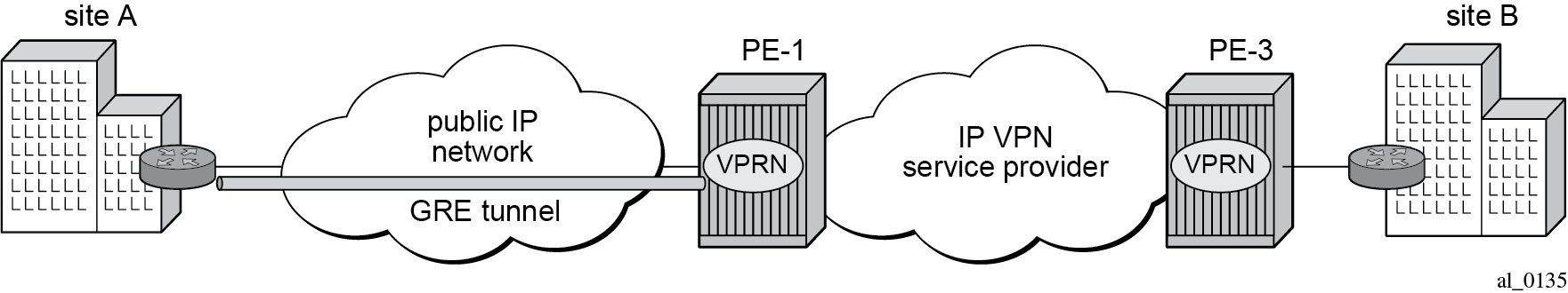
A common use case for IP/GRE tunneling is remote access to a VPRN over a public IP network because IP/GRE tunneling allows encapsulated packets to follow a path based on the outer IP header which is useful when the inner IP packet cannot or should not be forwarded natively over this path.
GRE allows packets of one protocol, the payload protocol, to be encapsulated by packets of another protocol, called the delivery protocol. GRE packet format shows the GRE packet format with an outer delivery header, GRE header, and payload packet:
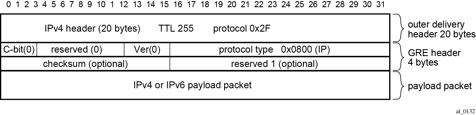
The outer delivery and GRE header for outgoing traffic is as follows.
Outer delivery header
The source address in the IPv4 delivery header is the configured source address.
The destination address in the IPv4 delivery header is the configured remote IP (or the backup remote IP) address.
The IP protocol value in the IPv4 delivery header is 0x2F or 47 (GRE).
The DSCP in the IPv4 outer delivery header is:
set to the value configured for the tunnel
otherwise, the DSCP value from the payload packet is copied into the outer delivery header.
The TTL in the IPv4 outer delivery header is set to 255.
GRE header
The checksum (C) bit in the GRE header is set to 0 (no checksum present).
The version in the GRE header is 0.
The protocol type is 0x0800 for IPv4.
The outer delivery and GRE header for incoming traffic is as follows:
Outer delivery header
If the packet is a fragment (more fragments=1, non-zero fragment offset), it is dropped.
If the checksum (C) bit in the GRE header is set, then the included checksum is validated; if the checksum is incorrect, the packet is discarded.
If the version in the GRE header is not 0, the packet is discarded.
If the source and destination address pair in the IPv4 delivery header is any other combination, the packet is dropped.
GRE header
If the checksum (C) bit in the GRE header is set, then the included checksum is validated; if the checksum is incorrect, the packet is discarded.
If the version in the GRE header is not 0, the packet is discarded.
Implementation
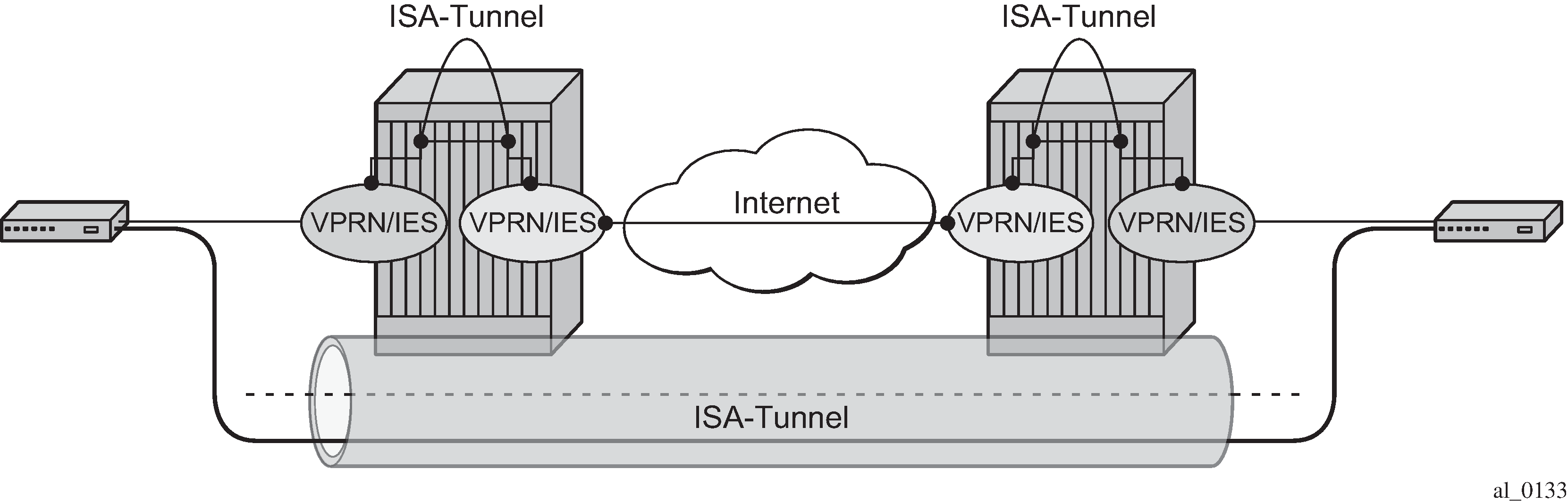
Encapsulation, de-encapsulation and other datapath operations related to IP/GRE are handled by the ISA-tunnel MDA.
For GRE tunnels configured as SDPs (which are not covered in this chapter), no ISA-tunnel MDA is required.
SR OS nodes initially supported the IP/GRE tunnels with static routes and BGP. IP/GRE tunnels have been enhanced by adding support for OSPF and BFD on private tunnel interfaces (used with static routes, OSPF, or BGP) and GRE protection by tunneling into an IPSec tunnel.
Configuration
ISA-tunnel MDA
The ISA-tunnel MDA supports IP/GRE and IPSec tunnels and is configured as follows:
# on PE-1:
configure {
    card 1 {
        mda 2 {
            mda-type isa2-tunnel
        }
    }
    card 2 {
        mda 2 {
            mda-type isa2-tunnel
        }
    }
The following command checks the MDA configuration:
[/]
A:admin@PE-1# show mda

===============================================================================
MDA Summary
===============================================================================
Slot  Mda   Provisioned Type                            Admin     Operational
                Equipped Type (if different)            State     State
-------------------------------------------------------------------------------
1     1     p10-10g-sfp                                 up        up
      2     isa2-tunnel                                 up        up
                p-isa2-ms
2     1     p10-10g-sfp                                 up        up
      2     isa2-tunnel                                 up        up
                p-isa2-ms
===============================================================================
Tunnel groups and tunnel group restrictions
The first step of the GRE tunnel configuration is to configure a tunnel group.
A tunnel group can have one tunnel ISA designated primary and optionally one tunnel-ISA designated backup. When a GRE tunnel is created, it is assigned to the primary tunnel-ISA in its tunnel group. If the primary tunnel-ISA fails, the backup tunnel-ISA (if not already claimed by another tunnel group) takes over for the failed card.
[ex:/configure isa]
A:admin@PE-1# tunnel-group 1 ?

 tunnel-group

 Immutable fields      - isa-scale-mode

 admin-state           - Administrative state of the ISA tunnel group
 apply-groups          - Apply a configuration group at this level
 apply-groups-exclude  - Exclude a configuration group at this level
 description           - Text description
 ipsec-responder-only  - Act as an IKE responder except upon MC-IPsec switchover
 isa-scale-mode        ^ Tunnel limit on each ISA for the tunnel group
 reassembly            + Enter the reassembly context
 spi-range-index       - SPI range index to use for the tunnel group
 stats-collection      + Enter the stats-collection context
 strict-esp-sequence-  - Enable strict ESP sequence number ordering
  number-ordering

 Choice: redundancy
 multi-active         :+ Enable the multi-active context
 backup               :- IPsec module configured in the slot to the IPsec group
 primary               - Primary ISA IPsec module assigned for the tunnel group


# on PE-1:
configure {
    isa {
        tunnel-group 1 {
            admin-state enable
            isa-scale-mode tunnel-limit-2k
            primary 1/2
            backup 2/2
        }
The failed tunnels are re-established using a cold-standby on the backup tunnel-ISA. Cold-standby means the backup tunnel-ISA has no state or configuration information about the tunnels before the failure.
A tunnel ISA cannot be primary for more than one tunnel group:
*[ex:/configure isa tunnel-group 2]
A:admin@PE-1# primary 1/2

*[ex:/configure isa tunnel-group 2]
A:admin@PE-1# commit
MINOR: IPSECGRPMGR #1003: configure isa tunnel-group 2 primary
- The specified MDA is primary in another Tunnel Group - configure isa tunnel-group 1 primary
MINOR: IPSECGRPMGR #1003: configure isa tunnel-group 1 primary
- The specified MDA is primary in another Tunnel Group - configure isa tunnel-group 2 primary
A tunnel ISA cannot be primary in one tunnel group and backup in another tunnel group:
*[ex:/configure isa tunnel-group 2]
A:admin@PE-1# primary 2/2

*[ex:/configure isa tunnel-group 2]
A:admin@PE-1# backup 1/2

*[ex:/configure isa tunnel-group 2]
A:admin@PE-1# commit
MINOR: IPSECGRPMGR #1003: configure isa tunnel-group 2 backup
- The specified MDA is primary in another Tunnel Group - configure isa tunnel-group 1 primary
MINOR: IPSECGRPMGR #1003: configure isa tunnel-group 1 backup
- The specified MDA is primary in another Tunnel Group - configure isa tunnel-group 2 primary
The following commands shows the ISA tunnel group (after tunnel group 2 has been removed):
[/]
A:admin@PE-1# show isa tunnel-group

===============================================================================
ISA Tunnel Groups
===============================================================================
Tunnel    PrimaryIsa             BackupIsa    ActiveIsa    Admin     Oper
GroupId                                                    State     State
-------------------------------------------------------------------------------
1         1/2                    2/2          1/2          Up        Up
-------------------------------------------------------------------------------
No. of ISA Tunnel Groups: 1
===============================================================================
The following command shows the number of the IP (GRE) tunnels, after configuring IES and VPRN services with tunnel interfaces:
[/]
A:admin@PE-1# show ip tunnel count
--------------------------------------------------------------------------------
IP Tunnels: 2
--------------------------------------------------------------------------------
The following command shows all IP tunnels:
[/]
A:admin@PE-1# show ip tunnel

===============================================================================
IP Tunnels
===============================================================================
TunnelName                       SapId                          SvcId      Admn
 Local Address                                                  DlvrySvcId Oper
  OperRemoteAddress
-------------------------------------------------------------------------------
gre-tunnel-1                     tunnel-1.private:1             1          Up
 192.168.1.1                                                    IES 2      Up
  192.168.2.1
protected-gre-tunnel             tunnel-1.private:5             3          Up
 192.168.11.1                                                   VPRN 3     Up
  192.168.22.1
-------------------------------------------------------------------------------
IP Tunnels: 2
===============================================================================
The detailed tunnel information is as follows:
[/]
A:admin@PE-1# show ip tunnel "gre-tunnel-1"

===============================================================================
IP Tunnel Configuration Detail
===============================================================================
Service Id       : 1                    Sap Id           : tunnel-1.private:1
Tunnel Name      : gre-tunnel-1
Description      : None
GRE Header       : Yes
Delivery Service : IES 2
GRE Keys Set     : False
GRE Send Key     : N/A                  GRE Receive Key  : N/A
Admin State      : Up                   Oper State       : Up
Source Address   : 192.168.1.1
Remote Address   : 192.168.2.1
Backup Address   : (Not Specified)
Oper Remote Addr : 192.168.2.1
DSCP             : None
Reassembly       : inherit
Clear DF Bit     : false                IP MTU           : max
Encap IP MTU     : max
Pkt Too Big      : true
Pkt Too Big Num  : 100                  Pkt Too Big Intvl: 10 secs
Frag Required    : true
Frag Req Count   : 100                  Frag Req Interval: 10 secs
Propagate IPv6 P*: true
Propagate IPv4 P*: true
Oper Flags       : None
Transport Profile: (Not Specified)
Last Oper Changed: 06/25/2025 07:31:30
Host ISA         : 1/2
TCP MSS Adjust
    Public       : Disabled
    Private      : Disabled

-------------------------------------------------------------------------------
Target Address Table
-------------------------------------------------------------------------------
Destination IP                          IP Resolved Status
-------------------------------------------------------------------------------
10.0.0.2                                Yes
-------------------------------------------------------------------------------

===============================================================================
IP Tunnel Statistics: gre-tunnel-1
===============================================================================
Errors Rx        : 0                    Errors Tx        : 0
Pkts Rx          : 111                  Pkts Tx          : 108
Bytes Rx         : 7963                 Bytes Tx         : 7819
Key Ignored Rx   : 0                    Too Big Tx       : 0
Seq Ignored Rx   : 0
Vers Unsup. Rx   : 0
Invalid Chksum Rx: 0
Key Mismatch Rx  : 0
===============================================================================

===============================================================================
Fragmentation Statistics
===============================================================================
Encapsulation Overhead                 : 24
Temporary Private MTU                  : max
Pre-Encapsulation
    Fragmentation Count                : 0
    Last Fragmented Packet Size        : 0
Post-Encapsulation
    Fragmentation Count                : 0
    Last Fragmented Packet Size        : 0
===============================================================================
===============================================================================
* indicates that the corresponding row element may have been truncated.
Interfaces
The interface toward the Internet (or WAN):
can be a network interface, a VPRN interface, or an IES interface
provides IP reachability
The tunnel public interface:
can be a VPRN interface or an IES interface
represents the public side of the tunnel-ISA
The delivery VPRN or IES service (the service connected to the Internet) must have at least one IP interface associated with a public tunnel SAP to receive and process GRE encapsulated packets.
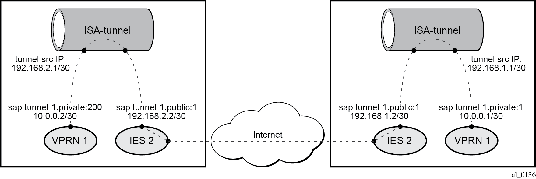
The public tunnel SAP type has the format tunnel-id.private|public:tag (where the id corresponds to the tunnel group). GRE for remote access to a VPRN service shows the example topology, where CE-2 in customer site A is connected to PE-1.
The IES service with public tunnel SAP is configured on PE-1 as follows:
[ex:/configure service ies "IES 2" interface "int-tunnel-public"]
A:admin@PE-1# sap ?

 [sap-id] (<port-and-encap> | <expression>)
 <port-and-encap>                             - null                  - (<port-id>|<lag-name>|<aps-id>)
---snip---
                                                tunnel-id             - tunnel-<1..64>.(private|
                                                                         public):<tag>
---snip---


# on PE-1:
configure {
    service {
        ies "IES 2" {
            admin-state enable
            service-id 2
            customer "1"
            interface "int-PE-1-CE-2" {
                sap 1/1/2:2 {
                }
                ipv4 {
                    primary {
                        address 192.168.12.1
                        prefix-length 24
                    }
                }
            }
            interface "int-tunnel-public" {
                # tos-marking-state untrusted         # default
                sap tunnel-1.public:1 {
                }
                ipv4 {
                    primary {
                        address 192.168.1.2
                        prefix-length 30
                    }
                }
            }
PE-1 has address 192.168.1.2/30 assigned to the interface "int-tunnel-public" in IES 2. In a similar way, CE-2 has address 192.168.2.2/30 assigned to the interface "int-tunnel-public" in IES 2.
To reach 192.168.2.0/30 on CE-2, the following static route is configured on PE-1:
# on PE-1:
configure {
    router "Base" {
        static-routes {
            route 192.168.2.0/30 route-type unicast {
                next-hop "192.168.12.2" {
                    admin-state enable
                }
            }
In a similar way, a static route is configured on CE-2 to reach 192.168.1.0/30 on PE-1.
Mask /32 is not supported on the public tunnel. When address 192.168.1.2/32 is configured on the interface "int-tunnel-public", the public tunnel cannot be created, as follows:
*[ex:/configure service ies "IES 2" interface "int-tunnel-public" ipv4 primary]
A:admin@PE-1# prefix-length 32

*[ex:/configure service ies "IES 2" interface "int-tunnel-public" ipv4 primary]
A:admin@PE-1# commit
MINOR: COMMON #238: configure service ies "IES 2" interface "int-tunnel-public" ipv4
primary prefix-length - Configuration change failed validation
- /32 address can be assigned only to the system or loopback interfaces.
- configure service ies "IES 2" interface "int-tunnel-public" sap tunnel-1.public:1
Therefore, the address configured on the interface has mask /30 instead of /32, as shown earlier.
The tunnel private interface:
can be an IES or VPRN interface
represents the private side of the tunnel ISA
The private tunnel SAP has the format tunnel-id.private|public:tag (where the id corresponds to the tunnel group) as shown in the following example where an unprotected GRE tunnel is configured in the SAP context.
[ex:/configure service vprn "VPRN 1" interface "int-gre-tunnel"]
A:admin@PE-1# sap ?

 [sap-id] (<port-and-encap> | <expression>)
 <port-and-encap>                             - null                  - (<port-id>|<lag-name>|<aps-id>)
---snip---
                                                tunnel-id             - tunnel-<1..64>.(private|
                                                                         public):<tag>
---snip---


# on PE-1:
configure {
    service {
        vprn "VPRN 1" {
            admin-state enable
            service-id 1
            customer "1"
            ---snip---

            interface "int-gre-tunnel" {
                tunnel true
                ipv4 {
                    addresses {
                        address 10.0.0.1 {
                            prefix-length 30
                        }
                    }
                }
                sap tunnel-1.private:1 {
                    ip-tunnel "gre-tunnel-1" {
                        gre-header {
                            admin-state enable
                        }
                        dest-ip 10.0.0.2 { }
                         ---snip---
It is not mandatory to have the same tag (internal dot1q) in private and public GRE tunnels.
sap tunnel-1.private:1 <=> sap tunnel-1.public:2
Unprotected GRE tunnel configuration
To associate an unprotected GRE tunnel with a private tunnel SAP, the ip-tunnel command is configured in the SAP context.
# on PE-1:
configure {
    service {
        vprn "VPRN 1" {
        ---snip---
            interface "int-gre-tunnel" {
                tunnel true
                ipv4 {
                    addresses {
                        address 10.0.0.1 {
                            prefix-length 30
                        }
                    }
                }
                sap tunnel-1.private:1 {
                    ip-tunnel "gre-tunnel-1" {
                        ---snip---
                       gre-header {
                            admin-state enable
                        }
                        dest-ip 10.0.0.2 { }
                        ---snip---
The dest-ip keyword followed by the private IP address of the remote tunnel endpoint is mandatory.
If this remote IP address is not within the subnet of the local private endpoint, then the tunnel does not come up.
The following parameters are configured in the ip-tunnel context:
The local IP address of the GRE tunnel. This is the source IPv4 address of GRE encapsulated packets sent by the delivery service. It must be an address in the subnet of the associated public tunnel SAP interface.
The remote IP address. If this address is reachable in the delivery service (there is a route), then this is the destination IPv4 address of GRE encapsulated packets sent by the delivery service.
The backup remote IP address. If the remote IP address of the tunnel is not reachable, then the backup remote IP address is the destination IPv4 address of GRE encapsulated packets sent by the delivery service.
The delivery service. This is the identifier or name of the IES or VPRN service where GRE encapsulated packets are injected and terminated. The delivery service can be the same service where the private tunnel SAP interface resides.
The DSCP marking in the outer IP header of GRE encapsulated packets. If this is not configured, then the default copies the DSCP from the inner IP header to the outer IP header.
# on PE-1:
configure {
    service {
        vprn "VPRN 1" {
            admin-state enable
            service-id 1
            customer "1"
            bgp-ipvpn {
                mpls {
                    admin-state enable
                    route-distinguisher "64496:1"
                    vrf-target {
                        community "target:64496:1"
                    }
                }
            }
            interface "int-gre-tunnel" {
                tunnel true
                ipv4 {
                    addresses {
                        address 10.0.0.1 {
                            prefix-length 30
                        }
                    }
                }
                sap tunnel-1.private:1 {
                    ip-tunnel "gre-tunnel-1" {
                        admin-state enable
                        delivery-service "IES 2"
                        dscp af22
                        remote-ip-address 192.168.2.1
                        local-ip-address 192.168.1.1
                        gre-header {
                            admin-state enable
                        }
                        dest-ip 10.0.0.2 { }
                    }
                }
            }
            ---snip---
A private tunnel SAP can have only one IP/GRE tunnel per SAP.
[ex:/configure service vprn "VPRN 1" interface "int-gre-tunnel" sap tunnel-1.private:1]
 A:admin@PE-1# ip-tunnel "gre-tunnel-2" {

*[ex:/configure service vprn "VPRN 1" interface "int-gre-tunnel" sap tunnel-1.private:1
                                                                         ip-tunnel "gre-tunnel-2"]
 A:admin@PE-1# commit
 MINOR: MGMT_CORE #232: configure service vprn "VPRN 1" interface "int-gre-tunnel"
sap tunnel-1.private:1 ip-tunnel "gre-tunnel-2"
- Reached maximum number of entries - maximum is 1 but has 2
IP/GRE tunneling via static route
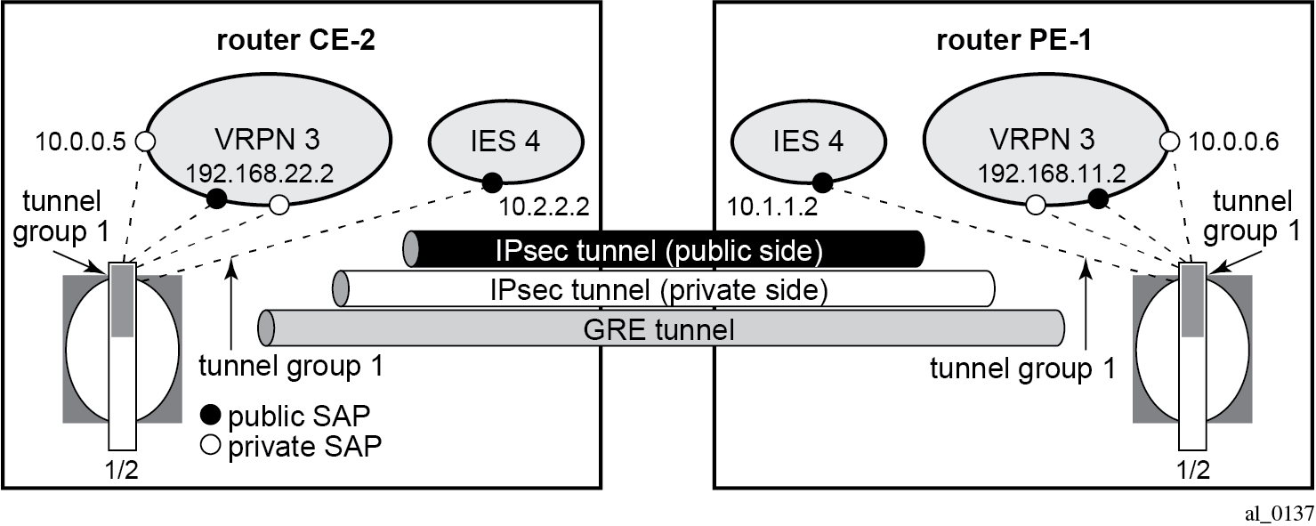
A static route can reference the GRE tunnel directly (by next-hop IP address) or the GRE tunnel can be the resolved next-hop for an indirect static route (GRE for remote access to a VPRN service).
The details of both ends on the GRE tunnel, at site A and PE-1, are shown in IP/GRE tunneling via static route. The node at the lefthand side is CE-2 at site A.
The following shows the configuration of VPRN 1 on PE-1.
# on PE-1:
configure {
    service {
        vprn "VPRN 1" {
            admin-state enable
            service-id 1
            customer "1"
            bgp-ipvpn {
                mpls {
                    admin-state enable
                    route-distinguisher "64496:1"
                    vrf-target {
                        community "target:64496:1"
                    }
                }
            }
            interface "int-gre-tunnel" {
                tunnel true
                ipv4 {
                    addresses {
                        address 10.0.0.1 {
                            prefix-length 30
                        }
                    }
                }
                sap tunnel-1.private:1 {
                    ip-tunnel "gre-tunnel-1" {
                        admin-state enable
                        delivery-service "IES 2"
                        remote-ip-address 192.168.2.1
                        local-ip-address 192.168.1.1
                        gre-header {
                            admin-state enable
                        }
                        dest-ip 10.0.0.2 { }
                    }
                }
            }
            interface "loopback1" {
                loopback true
                ipv4 {
                    primary {
                        address 172.16.1.1
                        prefix-length 32
                    }
                }
            }
            static-routes {
                route 172.16.2.1/32 route-type unicast {
                    next-hop "10.0.0.2" {
                        admin-state enable
                    }
                }
            }
        }
The configuration of the VPRN on CE-2 is similar.
The following command checks the static route status:
[/]
A:admin@PE-1# show router 1 static-route

===============================================================================
Static Route Table (Service: 1)  Family: IPv4
===============================================================================
Prefix                                        Nexthop Tag Met    Pref Type Act
   Next Hop                                    Interface
-------------------------------------------------------------------------------
172.16.2.1/32                                 0           1      5    NH   Y
   10.0.0.2                                    int-gre-tunnel
-------------------------------------------------------------------------------
No. of Static Routes: 1
===============================================================================
IP/GRE tunneling via BGP peering
In this section, the configuration has BGP running inside the GRE tunnel.
# on PE-1:
configure {
    service {
        vprn "VPRN 1" {
            admin-state enable
            service-id 1
            customer "1"
            autonomous-system 64496
            bgp-ipvpn {
                mpls {
                    admin-state enable
                    route-distinguisher "64496:1"
                    vrf-target {
                        community "target:64496:1"
                    }
                }
            }
            bgp {
                group "group-1" {
                    type internal
                    local-address 172.16.1.1
                    export {
                        policy "export-bgp-172.31"
                    }
                }
                neighbor "172.16.2.1" {
                    group "group-1"
                }
            }
            interface "int-gre-tunnel" {
                tunnel true
                ipv4 {
                    addresses {
                        address 10.0.0.1 {
                            prefix-length 30
                        }
                    }
                }
                sap tunnel-1.private:1 {
                    ip-tunnel "gre-tunnel-1" {
                        admin-state enable
                        delivery-service "IES 2"
                        remote-ip-address 192.168.2.1
                        local-ip-address 192.168.1.1
                        gre-header {
                            admin-state enable
                        }
                        dest-ip 10.0.0.2 { }
                    }
                }
            }
            interface "loopback1" {
                loopback true
                ipv4 {
                    primary {
                        address 172.16.1.1
                        prefix-length 32
                    }
                }
            }
            interface "loopback2" {
                loopback true
                ipv4 {
                    primary {
                        address 172.31.1.1
                        prefix-length 24
                    }
                }
            }
            static-routes {
                route 172.16.2.1/32 route-type unicast {
                    next-hop "10.0.0.2" {
                        admin-state enable
                    }
                }
            }
        }
It is mandatory to configure the autonomous system in the vprn context, otherwise the BGP session cannot be established.
The configuration of the VPRN on CE-2 is similar.
The following command on PE-1 shows the summary of the BGP sessions. The BGP session between peers 172.16.1.1 in VPRN 1 on PE-1 and 172.16.2.1 in VPRN 1 on CE-2 is established for address family IPv4.
[/]
A:admin@PE-1# show router 1 bgp summary all

===============================================================================
BGP Summary
===============================================================================
Legend : D - Dynamic Neighbor
===============================================================================
Neighbor
Description
ServiceId          AS PktRcvd InQ  Up/Down   State|Rcv/Act/Sent (Addr Family)
                      PktSent OutQ
-------------------------------------------------------------------------------
172.16.2.1
1               64496       7    0 00h01m08s 1/1/1 (IPv4)
                            7    0
-------------------------------------------------------------------------------
In this example, PE-1 exports BGP route 172.31.1.0/24 and CE-2 exports BGP route 172.31.2.0/24. The route table for VPRN 1 on PE-1 includes the following BGP route:
[/]
A:admin@PE-1# show router 1 route-table protocol bgp

===============================================================================
Route Table (Service: 1)
===============================================================================
Dest Prefix[Flags]                            Type    Proto     Age        Pref
      Next Hop[Interface Name]                                    Metric
-------------------------------------------------------------------------------
172.31.2.0/24                                 Remote  BGP       00h00m40s  170
       10.0.0.2                                                     1
-------------------------------------------------------------------------------
No. of Routes: 1
Flags: n = Number of times nexthop is repeated
       B = BGP backup route available
       L = LFA nexthop available
       S = Sticky ECMP requested
===============================================================================
IP/GRE tunneling via OSPFv2 peering
OSPF can be run on IES and VPRN IP interfaces associated with private IP/GRE tunnel SAPs.
All OSPF features are supported, including area 0 and non-area 0 support, virtual links, authentication, BFD, configurable protocol timers.
# on PE-1:
configure {
    service {
        vprn "VPRN 1" {
            admin-state enable
            service-id 1
            customer "1"
            bgp-ipvpn {
                mpls {
                    admin-state enable
                    route-distinguisher "64496:1"
                    vrf-target {
                        community "target:64496:1"
                    }
                }
            }
            interface "int-gre-tunnel" {
                tunnel true
                ipv4 {
                    addresses {
                        address 10.0.0.1 {
                            prefix-length 30
                        }
                    }
                }
                sap tunnel-1.private:1 {
                    ip-tunnel "gre-tunnel-1" {
                        admin-state enable
                        delivery-service "IES 2"
                        remote-ip-address 192.168.2.1
                        local-ip-address 192.168.1.1
                        gre-header {
                            admin-state enable
                        }
                        dest-ip 10.0.0.2 { }
                    }
                }
            }
            interface "loopback1" {
                loopback true
                ipv4 {
                    primary {
                        address 172.16.1.1
                        prefix-length 32
                    }
                }
            }
            ospf 0 {
                admin-state enable
                area 0.0.0.0 {
                    interface "int-gre-tunnel" {
                    }
                    interface "loopback1" {
                    }
                }
            }
The configuration on CE-2 is similar.
The following command shows the OSPF neighbors for VPRN 1:
[/]
A:admin@PE-1# show router 1 ospf neighbor

===============================================================================
Rtr vprn1 OSPFv2 Instance 0 Neighbors
===============================================================================
Interface-Name                   Rtr Id          State      Pri  RetxQ   TTL
   Area-Id
-------------------------------------------------------------------------------
int-gre-tunnel                   192.0.2.2       Full       1    0       39
   0.0.0.0
-------------------------------------------------------------------------------
No. of Neighbors: 1
===============================================================================
The OSPF routes in the routing table of VPRN 1 are as follows:
[/]
A:admin@PE-1# show router service-name "VPRN 1" route-table protocol ospf

===============================================================================
Route Table (Service: 1)
===============================================================================
Dest Prefix[Flags]                            Type    Proto     Age        Pref
      Next Hop[Interface Name]                                    Metric
-------------------------------------------------------------------------------
172.16.2.1/32                                 Remote  OSPF      00h01m02s  10
       10.0.0.2                                                     2
-------------------------------------------------------------------------------
No. of Routes: 1
Flags: n = Number of times nexthop is repeated
       B = BGP backup route available
       L = LFA nexthop available
       S = Sticky ECMP requested
===============================================================================
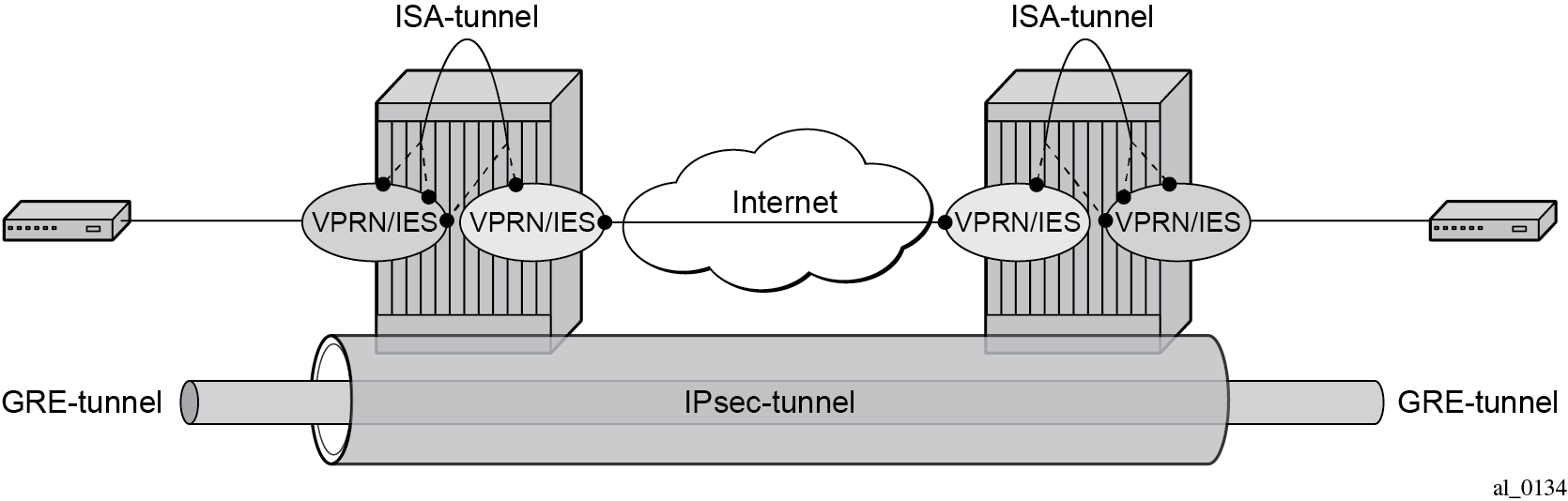
IP/GRE tunneling protection using IPSec tunnel mode
To provide protection against potential threats such as spoofing, the GRE packets can be encrypted and authenticated using IPSec.
GRE packets receive IPSec protection by forwarding them, after encapsulation by a tunnel-ISA, into an IPSec tunnel supported by another (or the same) tunnel ISA.
Note that when configuring GRE protection by an IPSec tunnel:
A GRE tunnel and its protecting IPSec tunnel may belong to the same or different tunnel groups (the same tunnel group is assumed in the following example).
A GRE tunnel and its protecting IPSec tunnel may be assigned to the same tunnel ISA (if they belong to the same tunnel group) or different tunnel ISAs.
A single IPSec tunnel can protect one or more GRE tunnels in addition to other IP traffic that meets the IPSec security policy.
The private IPSec tunnel SAP interface and public GRE tunnel SAP interface are always part of the same VPRN. The private GRE tunnel SAP interface can be part of this same VPRN or a different VPRN.
In the following example, the GRE tunnel and its protecting IPSec tunnel belong to the same tunnel group.
IPSec configuration
An ike-policy and ipsec-transform must be configured on PE-1 and CE-2, as follows:
# on PE-1, CE-2:
configure {
    ipsec {
        ike-policy 1 {
            ike-transform [1]
        }
        ike-transform 1 {
            dh-group group-5
        }
        ipsec-transform 1 {
            esp-encryption-algorithm aes-256
        }
The public and private side of the GRE tunnel and the private side of the IPSec tunnel are in the same VPRN, as shown in the following configuration example:
# on PE-1:
configure {
    service {
        vprn "VPRN 3" {
            admin-state enable
            service-id 3
            customer "1"
            ipsec {
                security-policy 1 {
                    entry 1 {
                        local-ip {
                            address 192.168.11.0/24
                        }
                        remote-ip {
                            address 192.168.22.0/24
                        }
                    }
                }
            }
            bgp-ipvpn {
                mpls {
                    admin-state enable
                    route-distinguisher "64496:3"
                    vrf-target {
                        community "target:64496:3"
                    }
                }
            }
            interface "int-private-gre-1" {
                tunnel true
                ipv4 {
                    addresses {
                        address 10.0.0.6 {
                            prefix-length 30
                        }
                    }
                }
                sap tunnel-1.private:5 {
                    ip-tunnel "protected-gre-tunnel" {
                        admin-state enable
                        delivery-service "VPRN 3"
                        remote-ip-address 192.168.22.1
                        local-ip-address 192.168.11.1
                        gre-header {
                            admin-state enable
                        }
                        dest-ip 10.0.0.5 { }
                    }
                }
            }
            interface "int-private-ipsec-1" {
                tunnel true
                sap tunnel-1.private:3 {
                    ipsec-tunnel "ipsec-tunnel-for-gre-tunnel" {
                        admin-state enable
                        key-exchange {
                            dynamic {
                                ike-policy 1
                                ipsec-transform [1]
                                pre-shared-key "pass"
                            }
                        }
                        tunnel-endpoint {
                            local-gateway-address 10.1.1.1
                            remote-ip-address 10.2.2.1
                            delivery-service "IES 4"
                        }
                        security-policy {
                            id 1
                        }
                    }
                }
            }
            interface "int-public-gre-1" {
                ipv4 {
                    primary {
                        address 192.168.11.2
                        prefix-length 24
                    }
                }
                sap tunnel-1.public:4 {
                }
            }
            static-routes {
                route 192.168.22.0/24 route-type unicast {
                    ipsec-tunnel "ipsec-tunnel-for-gre-tunnel" {
                        admin-state enable
                    }
                }
            }
        }
The following displays a configuration example of the public side of the IPSec tunnel:
# on PE-1:
configure {
    service {
        ies "IES 4" {
            admin-state enable
            service-id 4
            customer "1"
            interface "int2-PE-1-CE-2" {
                sap 1/1/2:4 {
                }
                ipv4 {
                    primary {
                        address 192.168.112.1
                        prefix-length 30
                    }
                }
            }
            interface "public-ipsec-1" {
                sap tunnel-1.public:3 {
                }
                ipv4 {
                    primary {
                        address 10.1.1.2
                        prefix-length 24
                    }
                }
            }
        }
The following static route is configured in the base router on PE-1:
# on PE-1:
configure {
    router "Base" {
        static-routes {
            route 10.2.2.0/24 route-type unicast {
                next-hop "192.168.112.2" {
                    admin-state enable
                }
            }
The configuration is similar on CE-2.
The following command shows that the tunnel "protected-gre-tunnel" with SAP tunnel-1.private:5 is up:
[/]
A:admin@PE-1# show ip tunnel

===============================================================================
IP Tunnels
===============================================================================
TunnelName                       SapId                          SvcId      Admn
 Local Address                                                  DlvrySvcId Oper
  OperRemoteAddress
-------------------------------------------------------------------------------
gre-tunnel-1                     tunnel-1.private:1             1          Up
 192.168.1.1                                                    IES 2      Up
  192.168.2.1
protected-gre-tunnel             tunnel-1.private:5             3          Up
 192.168.11.1                                                   VPRN 3     Up
  192.168.22.1
-------------------------------------------------------------------------------
IP Tunnels: 2
===============================================================================
The following command shows the IP/GRE tunnel information for this IPSec tunnel:
[/]
A:admin@PE-1# show ip tunnel "protected-gre-tunnel"

===============================================================================
IP Tunnel Configuration Detail
===============================================================================
Service Id       : 3                    Sap Id           : tunnel-1.private:5
Tunnel Name      : protected-gre-tunnel
Description      : None
GRE Header       : Yes
Delivery Service : VPRN 3
GRE Keys Set     : False
GRE Send Key     : N/A                  GRE Receive Key  : N/A
Admin State      : Up                   Oper State       : Up
Source Address   : 192.168.11.1
Remote Address   : 192.168.22.1
Backup Address   : (Not Specified)
Oper Remote Addr : 192.168.22.1
DSCP             : None
Reassembly       : inherit
Clear DF Bit     : false                IP MTU           : max
Encap IP MTU     : max
Pkt Too Big      : true
Pkt Too Big Num  : 100                  Pkt Too Big Intvl: 10 secs
Frag Required    : true
Frag Req Count   : 100                  Frag Req Interval: 10 secs
Propagate IPv6 P*: true
Propagate IPv4 P*: true
Oper Flags       : None
Transport Profile: (Not Specified)
Last Oper Changed: 06/25/2025 07:44:20
Host ISA         : 1/2
TCP MSS Adjust
    Public       : Disabled
    Private      : Disabled

-------------------------------------------------------------------------------
Target Address Table
-------------------------------------------------------------------------------
Destination IP                          IP Resolved Status
-------------------------------------------------------------------------------
10.0.0.5                                Yes
-------------------------------------------------------------------------------

===============================================================================
IP Tunnel Statistics: protected-gre-tunnel
===============================================================================
Errors Rx        : 0                    Errors Tx        : 0
Pkts Rx          : 0                    Pkts Tx          : 0
Bytes Rx         : 0                    Bytes Tx         : 0
Key Ignored Rx   : 0                    Too Big Tx       : 0
Seq Ignored Rx   : 0
Vers Unsup. Rx   : 0
Invalid Chksum Rx: 0
Key Mismatch Rx  : 0
===============================================================================

===============================================================================
Fragmentation Statistics
===============================================================================
Encapsulation Overhead                 : 24
Temporary Private MTU                  : max
Pre-Encapsulation
    Fragmentation Count                : 0
    Last Fragmented Packet Size        : 0
Post-Encapsulation
    Fragmentation Count                : 0
    Last Fragmented Packet Size        : 0
===============================================================================
===============================================================================
* indicates that the corresponding row element may have been truncated.
By default, the IPSec tunnel is down if it is not used by any traffic, as follows:
[/]
A:admin@PE-1# show ipsec tunnel

===============================================================================
IPsec Tunnels
===============================================================================
TunnelName                       LocalAddress      SvcId        Admn   Keying
  SapId                            RemoteAddress     DlvrySvcId   Oper   Sec
                                                                         Plcy
-------------------------------------------------------------------------------
ipsec-tunnel-for-gre-tunnel      10.1.1.1          3            Up     Dynamic
  tunnel-1.private:3               10.2.2.1          IES 4        Down   1
-------------------------------------------------------------------------------
IPsec Tunnels: 1
===============================================================================
After it is used by traffic, the status is changed to be up.
[/]
A:admin@PE-1# ping 10.0.0.5 router-instance "VPRN 3" interval 0.1 output-format summary
PING 10.0.0.5 56 data bytes
!!!!!
---- 10.0.0.5 PING Statistics ----
5 packets transmitted, 5 packets received, 0.00% packet loss
round-trip min = 4.58ms, avg = 4.94ms, max = 5.32ms, stddev = 0.245ms
The IPSec tunnel is now operationally up, as follows:
[/]
A:admin@PE-1# show ipsec tunnel

===============================================================================
IPsec Tunnels
===============================================================================
TunnelName                       LocalAddress      SvcId        Admn   Keying
  SapId                            RemoteAddress     DlvrySvcId   Oper   Sec
                                                                         Plcy
-------------------------------------------------------------------------------
ipsec-tunnel-for-gre-tunnel      10.1.1.1          3            Up     Dynamic
  tunnel-1.private:3               10.2.2.1          IES 4        Up     1
-------------------------------------------------------------------------------
IPsec Tunnels: 1
===============================================================================
BFD support on private tunnel interfaces
BFD is supported on IP interfaces associated with private IP/GRE tunnel SAPs. The BFD state of the interface can be used by static routes, OSPFv2, or BGP configured on the interface. It is not used to trigger a switchover to the backup remote IP address of the GRE tunnel.
The following displays a static route example:
# on PE-1:
configure {
    service {
        vprn "VPRN 1" {
            admin-state enable
            service-id 1
            customer "1"
            bgp-ipvpn {
                mpls {
                    admin-state enable
                    route-distinguisher "64496:1"
                    vrf-target {
                        community "target:64496:1"
                    }
                }
            }
            interface "int-gre-tunnel" {
                tunnel true
                ipv4 {
                    bfd {
                        admin-state enable      # Configure BFD on GRE tunnel interface
                    }
                    addresses {
                        address 10.0.0.1 {
                            prefix-length 30
                        }
                    }
                }
                sap tunnel-1.private:1 {
                    ip-tunnel "gre-tunnel-1" {
                        admin-state enable
                        delivery-service "IES 2"
                        remote-ip-address 192.168.2.1
                        local-ip-address 192.168.1.1
                        gre-header {
                            admin-state enable
                        }
                        dest-ip 10.0.0.2 { }
                    }
                }
            }
            interface "loopback1" {
                loopback true
                ipv4 {
                    primary {
                        address 172.16.1.1
                        prefix-length 32
                    }
                }
            }
            static-routes {
                route 172.16.2.1/32 route-type unicast {
                    next-hop "10.0.0.2" {
                        admin-state enable
                        bfd-liveness        # Enable BFD for static route
                    }
                }
            }
        }
The following command shows that the BFD session on interface "int-gre-tunnel" is up for protocol static:
[/]
A:admin@PE-1# show router 1 bfd session

===============================================================================
Legend:
  Session Id = Interface Name | LSP Name | Prefix | RSVP Sess Name | Service Id
  wp = Working path   pp = Protecting path
===============================================================================
BFD Session
===============================================================================
Session Id                                        State      Tx Pkts    Rx Pkts
  Rem Addr/Info/SdpId:VcId                      Multipl     Tx Intvl   Rx Intvl
  Protocols                                        Type     LAG Port     LAG ID
  Loc Addr                                                             LAG name
-------------------------------------------------------------------------------
int-gre-tunnel                                       Up          N/A        N/A
  10.0.0.2                                            3         1000       1000
  static                                         cpm-np          N/A        N/A
  10.0.0.1
-------------------------------------------------------------------------------
No. of BFD sessions: 1
===============================================================================
When no static routes are configured and OSPF is configured instead, the configuration of VPRN 1 on PE-1 is as follows:
# on PE-1:
configure {
    service  {
        vprn "VPRN 1" {
            admin-state enable
            service-id 1
            customer "1"
            bgp-ipvpn {
                mpls {
                    admin-state enable
                    route-distinguisher "64496:1"
                    vrf-target {
                        community "target:64496:1"
                    }
                }
            }
            interface "int-gre-tunnel" {
                tunnel true
                ipv4 {
                    bfd {
                        admin-state enable      # Configure BFD on GRE tunnel interface
                    }
                    addresses {
                        address 10.0.0.1 {
                            prefix-length 30
                        }
                    }
                }
                sap tunnel-1.private:1 {
                    ip-tunnel "gre-tunnel-1" {
                        admin-state enable
                        delivery-service "IES 2"
                        remote-ip-address 192.168.2.1
                        local-ip-address 192.168.1.1
                        gre-header {
                            admin-state enable
                        }
                        dest-ip 10.0.0.2 { }
                    }
                }
            }
            interface "loopback1" {
                loopback true
                ipv4 {
                    primary {
                        address 172.16.1.1
                        prefix-length 32
                    }
                }
            }
            ospf 0 {
                admin-state enable
                area 0.0.0.0 {
                    interface "int-gre-tunnel" {
                        bfd-liveness {          # Enable BFD on OSPF interface "int-gre-tunnel"
                        }
                    }
                    interface "loopback1" {
                    }
                }
            }
The following shows that the BFD session is up for protocol OSPF on interface "int-gre-tunnel":
[/]
A:admin@PE-1# show router 1 bfd session

===============================================================================
Legend:
  Session Id = Interface Name | LSP Name | Prefix | RSVP Sess Name | Service Id
  wp = Working path   pp = Protecting path
===============================================================================
BFD Session
===============================================================================
Session Id                                        State      Tx Pkts    Rx Pkts
  Rem Addr/Info/SdpId:VcId                      Multipl     Tx Intvl   Rx Intvl
  Protocols                                        Type     LAG Port     LAG ID
  Loc Addr                                                             LAG name
-------------------------------------------------------------------------------
int-gre-tunnel                                       Up          N/A        N/A
  10.0.0.2                                            3         1000       1000
  ospf2                                          cpm-np          N/A        N/A
  10.0.0.1
-------------------------------------------------------------------------------
No. of BFD sessions: 1
===============================================================================
When BGP is configured instead of OSPF, the configuration of VPRN 1 on PE-1 is as follows:
# on PE-1:
configure {
    service {
        vprn "VPRN 1" {
            admin-state enable
            service-id 1
            customer "1"
            autonomous-system 64496
            bgp-ipvpn {
                mpls {
                    admin-state enable
                    route-distinguisher "64496:1"
                    vrf-target {
                        community "target:64496:1"
                    }
                }
            }
            bgp {
                group "group-1" {
                    type internal
                    local-address 172.16.1.1
                }
                neighbor "172.16.2.1" {
                    bfd-liveness true               # Enable BFD on BGP
                    group "group-1"
                }
            }
            interface "int-gre-tunnel" {
                tunnel true
                ipv4 {
                    addresses {
                        address 10.0.0.1 {
                            prefix-length 30
                        }
                    }
                }
                sap tunnel-1.private:1 {
                    ip-tunnel "gre-tunnel-1" {
                        admin-state enable
                        delivery-service "IES 2"
                        remote-ip-address 192.168.2.1
                        local-ip-address 192.168.1.1
                        gre-header {
                            admin-state enable
                        }
                        dest-ip 10.0.0.2 { }
                    }
                }
            }
            interface "loopback1" {
                loopback true
                ipv4 {
                    bfd {
                        admin-state enable          # Configure BFD on loopback interface for BGP
                    }
                    primary {
                        address 172.16.1.1
                        prefix-length 32
                    }
                }
            }
            static-routes {
                route 172.16.2.1/32 route-type unicast {
                    next-hop "10.0.0.2" {
                        admin-state enable
                    }
                }
            }
The following command shows that the BFD session is up for protocol BGP on interface "loopback1":
*A:PE-1# show router 1 bfd session

===============================================================================
Legend:
  Session Id = Interface Name | LSP Name | Prefix | RSVP Sess Name | Service Id
  wp = Working path   pp = Protecting path
===============================================================================
BFD Session
===============================================================================
Session Id                                        State      Tx Pkts    Rx Pkts
  Rem Addr/Info/SdpId:VcId                      Multipl     Tx Intvl   Rx Intvl
  Protocols                                        Type     LAG Port     LAG ID
  Loc Addr                                                             LAG name
-------------------------------------------------------------------------------
loopback1                                            Up          N/A        N/A
  172.16.2.1                                          3         1000       1000
  bgp                                            cpm-np          N/A        N/A
  172.16.1.1
-------------------------------------------------------------------------------
No. of BFD sessions: 1
===============================================================================
IP/GRE termination – Advanced topics
DSCP value of outer delivery header
Default behavior — The DSCP value from the payload header is copied into the outer GRE header. This is a one to one copy and no QoS classifications are required. It is performed when no DSCP value is configured under the private GRE tunnel.
Non default behavior — DSCP is configured under the private SAP (following example using DSCP af41).
# on PE-1:
configure {
    service {
        vprn "VPRN 1" {
            interface "int-gre-tunnel" {
                tunnel true
                ipv4 {
                    addresses {
                        address 10.0.0.1 {
                            prefix-length 30
                        }
                    }
                }
                sap tunnel-1.private:1 {
                    ip-tunnel "gre-tunnel-1" {
                        admin-state enable
                        delivery-service "IES 2"
                        dscp af41                         # Configure DSCP value
                        remote-ip-address 192.168.2.1
                        local-ip-address 192.168.1.1
                        gre-header {
                            admin-state enable
                        }
                        dest-ip 10.0.0.2 { }
                    }
                }
            }
---snip---
The log filter output shows TOS=88 (DSCP=af41) in the public network.
[/]
A:admin@PE-1# show filter log 102

===============================================================================
Filter Log
===============================================================================
Admin state : Enabled
Description : (Not Specified)
Destination : Memory
Wrap        : Enabled
-------------------------------------------------------------------------------
Maximum entries configured : 1000
Number of entries logged   : 5
-------------------------------------------------------------------------------
2025/06/25 07:57:46  Ip Filter: 2:10  Desc:
SAP: tunnel-1.private:1  Direction: Egress
Src MAC: 00-03-fe-00-02-c9  Dst MAC: 00-00-00-07-a0-bd  EtherType: 0800
Src IP: 10.0.0.1  Dst IP: 10.0.0.2  Flags: 0  TOS: 88  TTL: 64 Len: 84
Protocol: ICMP  Type: Echo Request  Code: 0
---snip---
IP MTU
It is possible to configure the IP MTU of a private tunnel SAP interface. This sets the maximum IP packet size payload (including IP header) that can be sent into the tunnel (it applies to the packet size before the tunnel encapsulation is added).
# on PE-1:
configure {
    service {
        vprn "VPRN 1" {
            interface "int-gre-tunnel"
                ip-mtu 1476
            ---snip---
When an IPv4 packet needs to be forwarded to the tunnel and is larger than IP MTU bytes:
If the DF bit is clear, the payload packet is IP fragmented to the MTU size before the tunnel encapsulation.
If the DF bit is set, the payload packet is discarded.
The IP MTU range supported is from 512 to 9000 bytes.
The following command shows the configured IP MTU and the operational IP MTU for the GRE tunnel:
[/]
A:admin@PE-1# show router 1 interface "int-gre-tunnel" detail | match MTU
IP MTU           : 1476
IP Oper MTU      : 1476
Statistics and accounting
Collect-stats can be configured under public and private SAPs.
For public SAPs:
# on PE-1:
configure {
    service {
        ies "IES 2" {
            interface "int-tunnel-public" {
                sap tunnel-1.public:1 {
                    collect-stats true
For private SAPs:
# on PE-1:
configure {
    service {
        vprn "VPRN 1" {
            interface "int-gre-tunnel" {
                sap tunnel-1.private:1 {
                    collect-stats true
Filtering, policing, and QoS
An IP filter and QoS policy can be applied to the ingress and egress traffic of the private and public SAPs.
Public SAPs:
# on PE-1:
configure {
    service {
        ies "IES 2" {
            interface "int-tunnel-public"
                sap tunnel-1.public:1
                    ingress {
                        qos {
                            sap-ingress {
                                policy-name "sap-ingr-10"
                            }
                        }
                        filter {
                            ip "ip-1"
                        }
                    }
                    egress
                        qos {
                            sap-egress {
                                policy-name "sap-egr-20"
                            }
                        }
                        filter {
                            ip "ip-2"
                        }
                    }
            ---snip---
Private SAPs:
# on PE-1:
configure {
    service {
        vprn "VPRN 1" {
            interface "int-gre-tunnel" {
                sap tunnel-1.private:1 {
                    ingress {
                        qos {
                            sap-ingress {
                                policy-name "sap-ingr-10"
                            }
                        }
                        filter {
                            ip "ip-1"
                        }
                    }
                    egress {
                        qos {
                            sap-egress {
                                policy-name "sap-egr-20"
                            }
                        }
                        filter {
                            ip "ip-2"
                        }
                    }
                }
            ---snip---
Mirroring
The public and private SAPs can be mirrored. The following is in classic CLI:
# on PE-1:
debug
    mirror-source 99
        sap tunnel-1.private:3 egress ingress
        sap tunnel-1.public:1 egress ingress
        no shutdown
    exit
exit
Conclusion
This chapter provides configuration and show commands for IP/GRE termination.