
PFCP protocol
The core of session management is the PFCP protocol as defined in 3GPP TS 29.244, with BNG-specific extensions defined in BBF TR-459.
Protocol stack
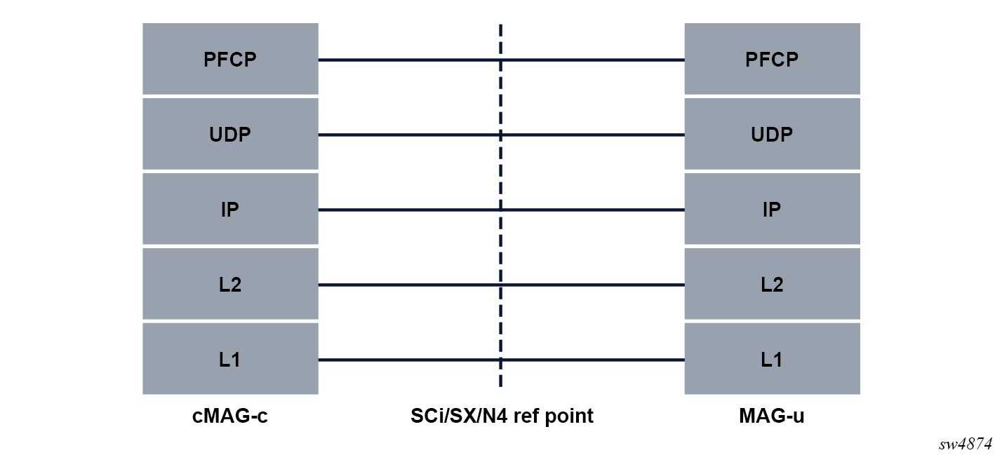
The PFCP protocol runs on top of UDP/IP. The UDP destination port for a request message uses port 8805, which is the registered port number for the PFCP protocol.
The following figure shows the PFCP protocol stack for the cMAG-c.
Generic PFCP message header
The following table describes the format of the generic PFCP message header.
| Bits | ||||||||
|---|---|---|---|---|---|---|---|---|
| Octets | 8 | 7 | 6 | 5 | 4 | 3 | 2 | 1 |
| 1 | Version | Spare | Spare | Spare | MP | S | ||
| 2 | Message Type | |||||||
| 3 | Message Length (1st Octet) | |||||||
| 4 | Message Length (2nd Octet) | |||||||
| m to (m+7) | If S=1, octets 5 to 12 contain the SEID If S=0, the SEID field is not present | |||||||
| n to (n+2) | Sequence Number | |||||||
| n+3 | Message Priority | Spare | ||||||
- MP indicates whether the Message Priority field is set. The Message Priority field is only set for messages related to a PFCP session.
- S indicates whether the SEID field is present. Messages related to a PFCP session always contain a session ID.
- Message Type indicates the type of the message and determines the content of the message beyond the header.
- Message Length is the total length of the packet.
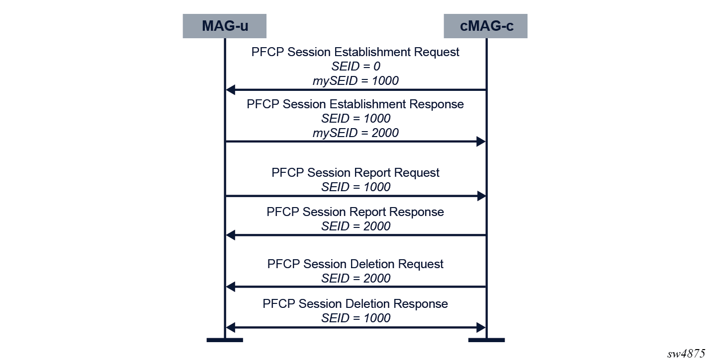
- SEID is the session ID. When the session ID is not known (for example, for the first message in a session), the session ID is set to 0. During PFCP session establishment, both the MAG-u and the cMAG-c allocate an SEID and signal their SEID to the other peer. Any subsequent message must use the SEID of the peer in the message header. See the following figure for an example of SEID allocation and use.
- Sequence Number is used to detect retransmission of PFCP packets.
- Message Priority defines a relative strict priority for the message processing. See TS 29.244 for more information.
PFCP messages overview
The following table describes the PFCP messages supported by the cMAG-c. See TS 29.244 for more information.
| Message type | Message | Description |
|---|---|---|
| 0 | Reserved | — |
| 1 | PFCP Heartbeat Request | Checks connectivity |
| 2 | PFCP Heartbeat Response | Confirms connectivity |
| 5 | PFCP Association Setup Request | Starts a PFCP association to exchange feature capabilities and node-wide parameters |
| 6 | PFCP Association Setup Response | Confirms a PFCP Association Setup Request |
| 7 | PFCP Association Update Request |
Signals feature capabilities or node-wide parameter updates |
| 8 | PFCP Association Update Response | Confirms the update |
| 9 | PFCP Association Release Request | Tears down the PFCP association |
| 10 | PFCP Association Release Response | Confirms the teardown |
| 12 | PFCP Node Report Request | Reports general, non-session-specific events |
| 13 | PFCP Node Report Response | Confirms the node report |
| 50 | PFCP Session Establishment Request | Creates a new PFCP session, with message containing all the parameters necessary to correctly create the forwarding state or in-band control plane state |
| 51 | PFCP Session Establishment Response | Confirms the creation of the PFCP session and contains the value of related MAG-u parameters, such as the SEID |
| 52 | PFCP Session Modification Request | Updates parameters of a PFCP session or requests an update of the usage information (counters) |
| 53 | PFCP Session Modification Response | Confirms the modification and can contain updated related MAG-u parameters or usage information (counters) or both |
| 54 | PFCP Session Deletion Request | Removes a PFCP session and its related state information |
| 55 | PFCP Session Deletion Response | Confirms the removal and includes a final usage update (counters) |
| 56 | PFCP Session Report Request | Notifies the cMAG-c of usage information updates (counters) or other state changes (for example, LCP keep-alive failures) |
| 57 | PFCP Session Report Response | Confirms receipt of the report |
Example call flows
Review call flow examples, including PFCP association and session setup, CoA handling, cMAG-c triggered updates, and PFCP connectivity failure.
Initial PFCP association and session setup
When either a cMAG-c or a MAG-u comes online, it sets up a PFCP association. The association request can be triggered either from the MAG-u or from the cMAG-c.
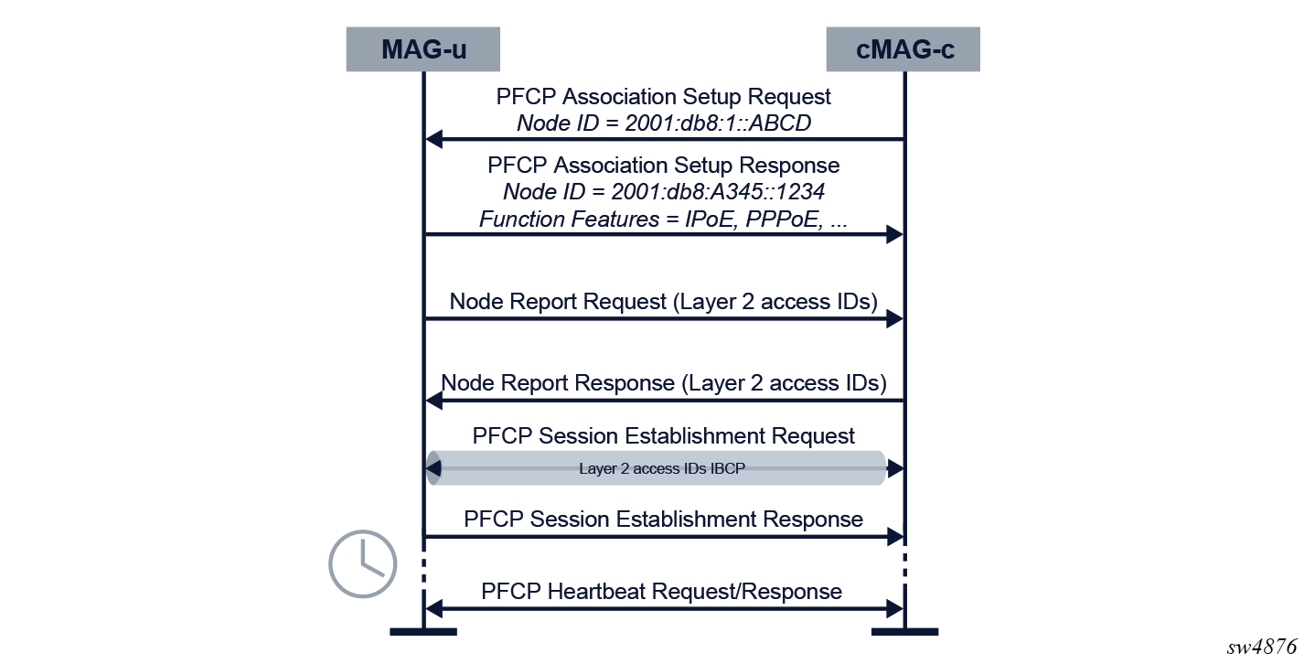
The following figure shows the initial PFCP association and session setup.
Description of the call flow
- The cMAG-c initializes the PFCP association setup and the MAG-u responds. During the association setup, both the MAG-u and the cMAG-c exchange parameters.
- The MAG-u immediately sends one or more PFCP Node Report Request messages to signal each Layer 2 access ID on that MAG-u.
- For each Layer 2 access ID, the cMAG-c creates a PFCP session on the MAG-u with both uplink and downlink PDRs for the forwarding of initial in-band control plane packets. See IBCP for more information.
- To monitor connectivity, the MAG-u and the cMAG-c exchange periodic heartbeat messages.
IPoE session setup
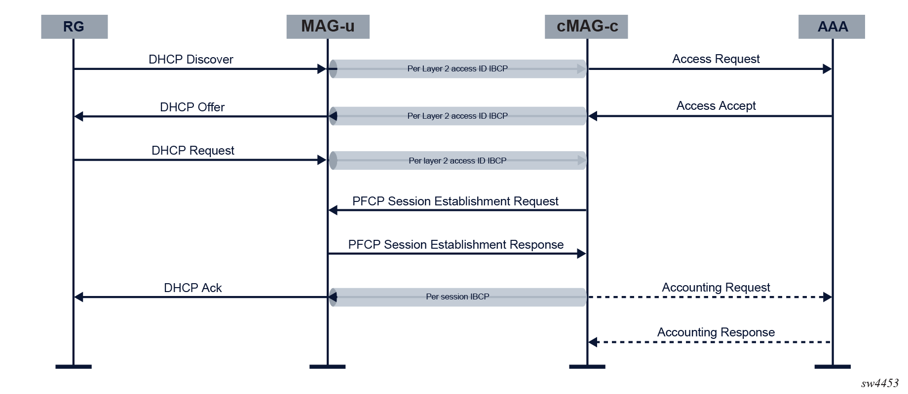
When the MAG-u receives a DHCP Discover message from an RG, it forwards the message to the cMAG-c over the the per Layer 2 access ID IBCP tunnel. The cMAG-c initiates the setup of the IPoE session.
The following figure shows the IPoE session setup.
Prerequisites
- The MAG-u has a PFCP association with the cMAG-c.
- The cMAG-c initialized the MAG-u with per Layer 2 access ID tunnels for the forwarding of control plane packets over the CPRi interface (GTP-U).
Description of the call flow
- The MAG-u forwards a DHCP Discover packet to the cMAG-c over the per Layer 2 access ID IBCP tunnel.
- The cMAG-c authorizes the IPoE session based on parameters in the DHCP message.
- The cMAG-c sends a DHCP Offer over the per Layer 2 access ID IBCP tunnel to the MAG-u, which decapsulates the DHCP packet and sends it to the RG.
- The MAG-u forwards the DHCP Request packet to the cMAG-c over the per Layer 2 access ID IBCP tunnel.
- The cMAG-c initializes the PFCP session and creates data plane rules and per-session IBCP tunnels on the MAG-u (PFCP session establishment procedure).
- The cMAG-c sends the DHCP Ack over the per-session IBCP tunnel to the MAG-u. The MAG-u decapsulates the DHCP packet and sends the packet to the RG.
- If accounting is provisioned, the cMAG-c starts accounting for the session.
CoA handling
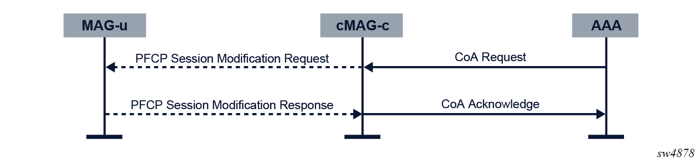
When the RADIUS server requests a change in client authorization for an active session, the cMAG-c triggers the MAG-u with the needed modifications.
The following figure shows the call flow process.
Description of the call flow
- The AAA server sends a CoA request directly to the cMAG-c.
- The cMAG-c processes the message and translates it to the necessary MAG-u
state changes. The state changes are signaled via a PFCP session modification
procedure.
If the cMAG-c determines that no MAG-u changes are required, the PFCP session modification procedure is skipped.
- The cMAG-c sends the CoA Ack to the AAA server.
cMAG-c triggered updates
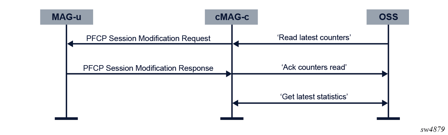
To perform specific tasks, such as getting up-to-date forwarding statistics for a specific subscriber session, the OSS may send a trigger to the cMAG-c.
The following figure shows a cMAG-c triggered accounting update.
Description of the call flow
- The OSS requests up-to-date forwarding statistics from the cMAG-c using the following
command.
tools subscriber-management session fetch-statistics-from-up - The cMAG-c processes the message and sends a PFCP Session Modification Request containing the Query URR IE to the MAG-u.
- The MAG-u sends the requested report in a PFCP Session Modification Response.
- The MAG-u finalizes the fetch operation.
- The OSS fetches up-to-date forwarding statistics.