| Load balancing | |||
|
| GO | ||
This topic describes the load balancing options for Lucent Communication Manager deployments.
Lucent Communication Manager offers the following load balancing options:
Internal load balancing
External load balancing
Lucent Feature Server 5000-based load balancing
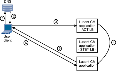
The standard Lucent CM configuration uses internal load balancing to distribute traffic across the application servers. The Lucent CM user clients use a URL to access to the Lucent CM system, which is translated by a DNS to the Virtual IP (VIP) address.
Load balancing is performed for login requests. The load balancer forwards a login request that comes into the single (virtual) IP address to one of the available application servers. Load balancing is performed on a round-robin basis. Location of the node or traffic load is not taken into consideration. Once connected to the assigned application server, all subsequent requests are handled by the server that is assigned to the session.
One load balancer acts as active load balancer. A second optional load balancer acts as standby. Heartbeat daemons run on the active and the standby load balancers. When the heartbeat daemon of the standby cannot hear the heartbeat message from the active in the specified time, it will take over the virtual IP address to provide the load-balancing service.
When the failing load balancer recovers, it becomes the standby load balancer.
Load balancing is based on Linux Virtual Server technology. Refer to http://www.linuxvirtualserver.org/
This load balancing option requires the active and standby load balancers to be on the same IP subnet, and is typically used in single-site deployments.
Internal load balancing process:

The following stages are performed during internal load balancing:
| 1 |
The user logs in using the login URL |
| 2 |
A DNS resolves the URL to the virtual IP address of the active load balancer of the Lucent CM system and returns the IP address to the user client. |
| 3 |
The user client sends the login request to the active load balancer of the Lucent CM system. |
| 4 |
The active load balancer redirects the login request to an application node. |
| 5 |
The application node logs in the user and returns its IP address to the user client. |
| 6 |
The user client uses the IP address to send subsequent messages to the application node directly. |
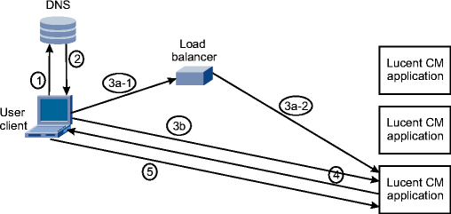
External load balancing bypasses the internal Lucent CM load balancers and does not use a virtual IP address.
The following options are available to distribute client login requests:
Use external load balancer
Use a DNS with load balancing capabilities
The external load balancer or DNS distributes incoming logins from user clients among the available Lucent CM application nodes.
External load balancing is typically used in geographical High Availability configurations.
The external load balancer must ensure that load balancer failures are detected and fail-overs are performed.
External load balancing process:

The following stages describe the external load balancing process:
Lucent Feature Server 5000-based load balancing uses Lucent CM-to-FS 5000 mapping. Upon startup of Lucent CM and FS 5000, every Lucent CM node connects to each FS 5000. Each Lucent CM node registers an equal number of users on their connection (each user is registered on only one connection).
An external DNS resolves user client logins to any of the application nodes. The application node checks its registration table to see if the user is registered with the node. If not, the application node redirects the user client login to the proper application node. All subsequent traffic from the user is directed to the application node where the user is registered.
Lucent Feature Server 5000-based load balancing can be used as the sole load balancing method in deployments where all users are Lucent Feature Server 5000 users and can be used in single-site and geographical High Availability configurations.
The DNS must be configured so it will select the next DNS login node in case of failure of that node. In case of a node failure, the FS 5000-based users are re-registered with the remaining application nodes and the registration tables are updated. The user clients will automatically reconnect when their connection is lost.
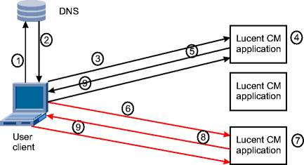
Lucent Feature Server 5000-based load balancing:

The application nodes have registered users during start-up.
The following stages describe the Lucent Feature Server 5000-based load balancing process:
| 1 |
The user logs in using the login URL. | ||||||
| 2 |
The DNS resolves the URL to the IP address of the default application node and returns the IP address to the user client. The default application node is referred to as the DNS login node. | ||||||
| 3 |
The user client sends the login request to the default application node. | ||||||
| 4 |
The application node checks the registration table to see if the user is registered with the application node.
| ||||||
| 5 |
The application node returns the IP address of the application node where the user is registered. | ||||||
| 6 |
The user client sends the login request to the application node. | ||||||
| 7 |
The application node checks the registration table to see if the user is registered with the application node. This must be true, since this is the node where the user is registered according to the registration tables. | ||||||
| 8 |
The application node logs in the user and returns its IP address to the user client. | ||||||
| 9 |
The user client uses the IP address to send subsequent messages to the application node directly. |
|
|
GO | ||
| © Lucent Technologies | |||