Ethernet transport
Overview
An Alcatel-Lucent 1665 DMX network accepts Ethernet frames at an ingress port and transmits them out of one or more egress ports. The egress port(s) can be on the same network element or on a different network element. If it is on a different network element, Ethernet frames are transmitted over a SONET network. To transport an Ethernet frame across the SONET network, the Ethernet Frame is moved between a LAN port and the SONET network.
Figure A-7: Ethernet transport through Alcatel-Lucent 1665 DMX
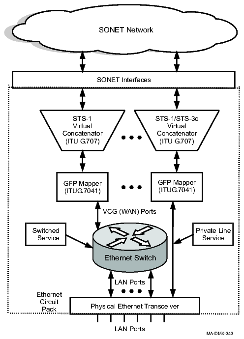
The following occurs to transport an Ethernet frame over a SONET network
-
Alcatel-Lucent 1665 DMX accepts an Ethernet Frame at an ingress LAN Port.
-
The Ethernet frame is accepted at an Ethernet switch's LAN port for switched services, processed, and then transmitted out one or more of its LAN and/or VCG (WAN) port(s). For Private Line circuit packs that support only non-switched services, the Ethernet frame is sent directly to the GFP mapper via a VCG port.
-
The generic framing procedure (GFP) mapper encapsulates the Ethernet frame into a GFP Frame.
-
The Virtual Concatenator maps the Ethernet stream into one or more SONET tributaries (time slots). This allows the network to carry traffic (Ethernet stream) at higher speeds than allowed by a single SONET tributaries (time slot). The group of virtually concatenated tributaries is referred to as a Virtual Concatenation Group (VCG).
-
The VCG is then placed on SONET tributaries and transmitted over the SONET network.
Generic framing procedure (GFP)
Generic Framing Procedure (GFP) is used to encapsulate Ethernet frames for transport over a SONET network. Alcatel-Lucent 1665 DMX uses frame-based GFP with the core header and no optional extension headers. The GFP Frame Check Sequence (FCS) is provisionable (on/off) on LNW63, LNW64, LNW87, LNW705 ports (ed-eport).
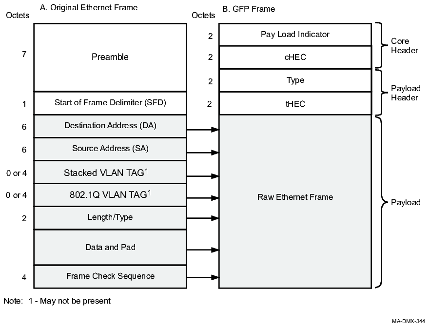
To encapsulate an Ethernet frame, the Ethernet preamble and Start of Frame Delimiter (SFD) fields are removed from the frame. A Type header and check (tHEC) is added to the Ethernet frame creating a GFP payload. The GFP payload is then scrambled and a Core header is added. The GFP frame is then sent to the Virtual Concatenator. The following figure shows the format of a GFP frame.
Figure A-8: GFP frame format
|
Section |
Field |
Description |
|---|---|---|
|
Core Header |
Payload Indicator (PLI) |
Binary number representing the number of octets in the GFP payload. |
|
Core Header Error Control (cHEC) |
CRC-16 checksum that protects the integrity of the contents of the Core Header. | |
|
Payload Header |
Type |
The type of information contained in the Payload field. The value is 01hex. |
|
Type Header Error Control (tHEC) |
CRC-16 checksum that protects the integrity of the contents of the Type Field. | |
|
Payload |
The raw Ethernet Frame (that is, the original Ethernet Frame without the Preamble and SFD. | |
In the opposite direction when the GFP Mapper receives a GFP frame from the Virtual Concatenator, it removes the Core Header and, using the cHEC field, performs a Header Error Check. If the header is correct, the payload area of the GFP is then unscrambled and the Type field and tHEC in the GFP header are checked for correctness. The Ethernet frame is extracted and the Preamble and SFD are added.
The GFP mapper at the far end of the network inserts idle GFP frames when there are no Ethernet frames to send. The near end GFP Mapper discards any idle GFP frames it receives over the SONET network. The idle GFP frames are not forwarded to the Ethernet Switch. (Private line packs do not contain an Ethernet switch.)
The GFP Mapper contains GFP queues that are used to store Ethernet frames while they are being processed.
The Generic Framing Procedure is defined in ITU-T G.7041/Y.1303 and ANSI T1X1.105 Sections 7.3.2 and 7.3.3.
Virtual concatenation
Virtual Concatenation is a standard inverse multiplex scheme for transporting a payload using multiple channels each of which has a lower capacity than the payload to be transported. It allows finer granularity in allocating the transport bandwidth than is available in standard contiguous concatenation (STS-3c, STS-12c, STS-48c, STS-192c etc.). For example, an STS-1 tributary has a usable bandwidth of approximately 48.4 Mb/s. This is too slow for a 1 Gbits/s Ethernet stream. An STS-48c tributary has approximately 2.4 Gb/s which would waste 1.4 Gb/s of bandwidth if used to carry a 1 Gb/s Ethernet stream.
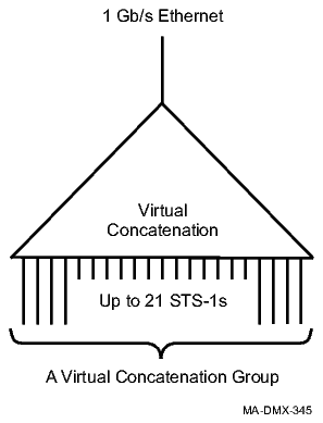
Using virtual concatenation, 21 STS-1 tributaries can be used providing an effective rate of approximately 1.02 Gb/s. Fewer STS-1 tributaries can be virtually concatenated to provide sub-rate (fractional rate) service.
The grouped SONET tributaries form a Virtual Concatenation Group (VCG). A VCG is treated as a single logical serial byte stream whose payload capacity equals that of the sum of the payload capacities of the constituent SONET tributaries. The following figure shows a virtual concatenation group.
Figure A-9: Virtual Concatenation Group
Individual tributaries in the VCG are independently transported through the SONET network. Only the initial and final SONET nodes perform the Virtual Concatenation. Since the VCGs are invisible to the intermediate SONET nodes, the intermediate nodes only need to transport normal SONET traffic and do not need to understand VCGs. This allows the tributaries to be transported through equipment which does not handle VCGs.
Differential delay buffers
Because the individual tributaries of a virtual concatenation group (VCAT) can take different paths through the SONET network, they may experience different delays through the network.
The table below provides the differential delay buffers for each of the Ethernet circuit packs.
|
Circuit Pack Name |
Delay (in milliseconds) |
|---|---|
|
LNW63 |
50 ms |
|
LNW64 |
108 ms |
|
LNW73/73C |
120 ms |
|
LNW74 |
64 ms |
|
LNW87 |
108 ms |
|
LNW170 |
50 ms |
|
LNW910 |
64 ms |
SONET transport
Ethernet circuit packs contain LAN ports and VCG ports. The LAN ports connect to external Ethernet equipment. The VCG ports connect to the OLIUs via Generic Framing (GFP) Mappers and Virtual Concatenation Groups (VCGs).
The OLIUs contain the hardware that perform the SONET cross-connections and process traffic at the SONET tributary level. They do not know about the embedded Ethernet frames or Virtual Concatenation Groups.
Connections to the SONET network can be configured to provide SONET layer protection. Alcatel-Lucent 1665 DMX supports three types of SONET protection: Unidirectional Path Switched Rings (UPSRs), Bidirectional Line Switched Rings (BLSRs), and 1+1.
Alcatel-Lucent 1665 DMX supports transport of Ethernet frames on the following:
Protected tributaries
On protected tributaries, both rings carry the same traffic placed in the same tributaries (time slots), but in opposite directions in the case of UPSR. UPSR protected cross-connections are provisioned as one 1wayPR cross-connections and two 1way cross-connections. BLSR protected cross-connections are provisioned using 1way cross-connections only.
Figure A-10: SONET protected cross-connections
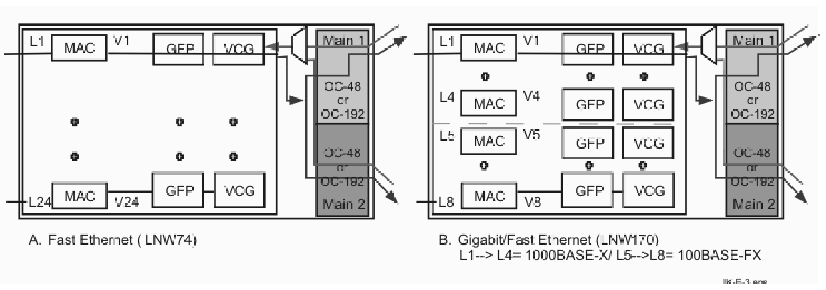
For the LNW63, LNW64, LNW74, LNW87, LNW170, and LNW910 circuit packs, all VCG ports can be used and all ports are supported regardless of STS mode. The picture above depicts the LNW74 and LNW170 in Private Line mode. The LNW170 can also function in switched mode. For figures depicting the LNW170 in switched mode, see Figure A-11, Multi-point cross-connections (unprotected) and/or Figure A-13, LNW170 Gigabit multipoint cross-connections (unprotected).
Unprotected tributaries
In the case of UPSR unprotected tributaries, the two sides of the ring carry different traffic. Each VCG is connected to only one side of the ring.
1-way unswitched cross-connections provide unprotected SONET connections to Ethernet circuit packs on a UPSR. On BLSR w/NUT, only 1way cross-connections are used. Each can be used to form two individual connections. One VCG is connected to MAIN 1 while the other VCG is connected to Main 2.
The following figure shows examples of the multipoint cross-connections provisioned by way of 1-way and 1-way unswitched cross-connects.
Figure A-11: Multi-point cross-connections (unprotected)
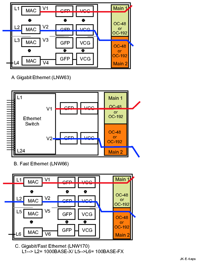
On the LNW74 circuit packs, the odd number VCGs are paired with the next higher number VCG (VCG 1 is paired with VCG 2, and VCG 3 is paired with VCG 4.) For example, VCG 2 must be connected to one OLIU when VCG 1 is provisioned to be connected to the other OLIU. Both cross-connections use the same SONET tributaries. The following figure shows an example of the VCG port pairing.
Figure A-12: Gigabit multipoint cross-connections (unprotected)

Multipoint cross-connections can either be used as two unprotected point-to-point connections or as part of a packet ring. If they are used as part of a packet ring, the Ethernet switch will process traffic received on one side of the packet ring before it is forwarded out the other side of the ring.
On the LNW63, LNW64, LNW74, LNW87, LNW170, and LNW910, any VCG can be connected to any OLIU. Additionally, the pairing of VCG ports for multipoint applications is not fixed. As the figure below demonstrates, V1 and V2 are paired in the shelf on the left while V1 and V3 are paired in the shelf on the right.
Figure A-13: LNW170 Gigabit multipoint cross-connections (unprotected)

A multipoint cross-connection is made up of multiple 1-way or 1-way unprotected cross-connections.
|
STS-1 Mode |
STS-3c Mode | ||
|---|---|---|---|
|
Port |
Paired with Port... |
Port |
Paired with Port... |
|
1 |
13 |
1 |
9 |
|
2 |
14 |
2 |
10 |
|
3 |
15 |
3 |
11 |
|
4 |
16 |
4 |
12 |
|
5 |
17 |
5 |
13 |
|
6 |
18 |
6 |
14 |
|
7 |
19 |
7 |
15 |
|
8 |
20 |
8 |
16 |
|
9 |
21 |
9 |
1 |
|
10 |
22 |
10 |
2 |
|
11 |
23 |
11 |
3 |
|
12 |
24 |
12 |
4 |
|
13 |
1 |
13 |
5 |
|
14 |
2 |
14 |
6 |
|
15 |
3 |
15 |
7 |
|
16 |
4 |
16 |
8 |
|
17 |
5 |
||
|
18 |
6 |
||
|
19 |
7 |
||
|
20 |
8 |
||
|
21 |
9 |
||
|
22 |
10 |
||
|
23 |
11 |
||
|
24 |
12 |
||
Ethernet-to-Ethernet hairpin cross-connections
Ethernet-to-Ethernet hairpin cross-connections are used to connect a circuit pack to another circuit pack within the same Alcatel-Lucent 1665 DMX. The cross-connection goes through either Main 1 or Main 2, but not over the SONET ring.
Hairpin cross-connections with an Ethernet circuit pack are used to either connect a VCG on that circuit pack with a VCG on another circuit pack or to connect a VCG with an OLIU located in a function or growth slot. Hairpin connections between VCG ports are used to combine Ethernet traffic from different cards before it is transmitted over a packet ring or out of a LAN port. The following figure shows examples of 1-way hairpin cross-connections between two Ethernet circuit packs.
Figure A-14: Ethernet-to-Ethernet hairpin cross-connections
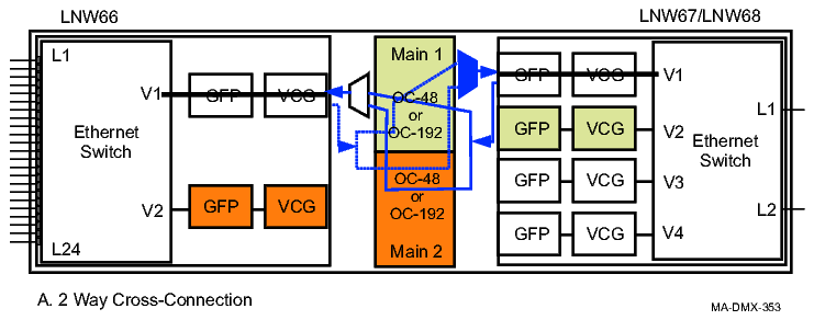
The table below details the support of 1way cross-connections between Ethernet packs. For hairpins between packs on the same shelf, only 1way cross-connections are used.
Table A-3: 1way cross-connection support
|
From |
To |
|---|---|
|
LNW63 |
LNW63, LNW64, LNW74, LNW87, LNW170, LNW910 |
|
LNW64 |
LNW63, LNW64, LNW74, LNW87, LNW170, LNW910 |
|
LNW73/73C |
LNW73/73C |
|
LNW74 |
LNW63, LNW64, LNW74, LNW87, LNW170, LNW910 |
|
LNW87 |
LNW63, LNW64, LNW74, LNW87, LNW170, LNW910 |
|
LNW170 |
LNW63, LNW64, LNW74, LNW87, LNW170, LNW910 |
|
LNW910 |
LNW63, LNW64, LNW74, LNW87, LNW170, LNW910 |
Ethernet LAN/VCG port density
The Ethernet Switch, also referred to as a Media Access Control (802.1D MAC) bridge, processes the Ethernet frames and handles Virtual LANs, frame priority, frame forwarding, and switching functions. The ports on the customer's side of the switch are referred to as LAN ports, and the ports on the SONET side are referred to as VCG or WAN Ports.
|
Circuit pack |
Number of ports |
Maximum capacity of a VCG port | ||
|---|---|---|---|---|
|
Name |
LAN port line rate |
LAN (Boundary) |
VCG (Interior) | |
|
LNW63 |
1 Gbps |
4 |
4 |
1 Gbps |
|
LNW64 |
1 Gbps |
8 |
8 |
1 Gbps |
|
LNW74 |
10/100 Mbps |
24 |
24 |
100 Mbps |
|
LNW87 |
1 Gbps |
4 |
4 |
1 Gbps |
|
LNW170 1 |
1 Gbps and 100 Mbps |
8 |
8 (Private line mode) 32 (Switched mode) |
2.5 Gbps |
|
LNW87 |
1 Gbps |
4 |
4 |
1 Gbps |
|
LNW910 |
100 Mbps, 1 Gbps, 10GbE |
11 |
64 |
10 Gbps |
Notes:
QoS provisioning on EoS VCGs in transparent mode allows LNW170 VCGs i transparent mode to be provisioned as either interior or boundary.
Virtual LANs (VLANs)
A virtual LAN (VLAN) is a logical grouping of LAN ports, possibly spread across multiple Alcatel-Lucent 1665 DMX nodes, that act as if they comprise a single LAN. Since a physical LAN can be associated with multiple virtual LANs, VLANs can be used to segregate traffic across a network. VLANs can be used to segregate different types of traffic for a single customer or to separate traffic belonging to multiple subscribers.
VLANs operate at the Ethernet (MAC) Layer. This allows different VLANs to be carried on the same physical media and hides the VLANs from higher-level protocols (for example, TCP and IP). The higher-level protocols treat each VLAN as if it was a separate physical LAN. VLAN-aware Ethernet Switches will forward VLAN traffic only on ports assigned to that VLAN. A port can be part of several VLANs and a VLAN can be assigned to several ports.
A frame's VLAN can be assigned either by the subscriber's equipment or by network equipment. User equipment specifies the VLAN by including a VLAN Tag in the frame. Alcatel-Lucent 1665 DMX determines a frame's VLAN either from the frame's existing VLAN Tag or by the default VLAN ID assigned to the frame's ingress port. Alcatel-Lucent 1665 DMX can be provisioned to drop frames that do not contain a tag.
VLAN tags
VLAN Tags are located in the Ethernet Header. The following figure shows the format of Ethernet frames without a VLAN Tag, frames with a VLAN Tag, and the format of the VLAN Tag.
Figure A-15: Ethernet frame format
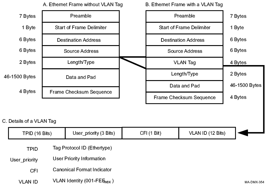
VLAN Tags can be generated by either user equipment or a switch. If a switch adds a VLAN Tag to a frame, it must also recalculate the frame's Checksum (FCS). Alcatel-Lucent 1665 DMX supports provisioning of 4093 VLAN IDs within the range of 1–4093. Additional information about VLAN tags can be found in IEEE 802.1Q.
Stacked VLANs (VLAN transparency)
In order to allow carriers to administer VLAN IDs independent of their subscribers, Alcatel-Lucent 1665 DMX can be provisioned to add a second VLAN Tag to Ethernet Frames. This tag, referred to as a Port Tag or Stacked VLAN Tag, can be used by the service provider to identify and segregate customer (subscriber) traffic. The following figure shows the format of an Ethernet frame that contains stacked VLAN tags.
Figure A-16: Ethernet frame format with stacked VLAN tags
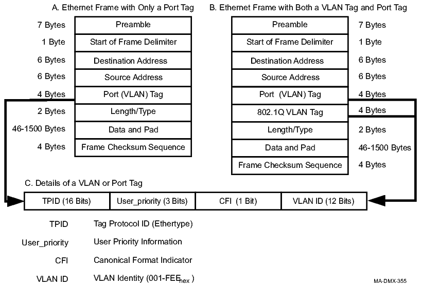
The port tag is formatted according to IEEE 802.1Q except:
Alcatel-Lucent 1665 DMX is capable of handling frames with multiple layers of VLAN tags; ultimately the limit is that frames greater than the MTU size are rejected as too large. When processing VLAN tags, Alcatel-Lucent 1665 DMX only looks at the outermost tag (that is, the one that most closely follows the Source Address) that it recognizes. Recognition of a tag is based on the TPID value. In 802.1Q mode, the expected TPID value is 8100hex. In transparent mode, the expected TPID value is provisioned by the user, with the default value being FFFFhex. Legal provisioned values for TPID are between 0601hex and FFFFhex. These TPID values are also used to identify any tags inserted by Alcatel-Lucent 1665 DMX.
Based on provisioning at the network ingress and egress points, it is possible for an Ethernet frame to enter and leave the network with a different number of VLAN tags.
Priorities
Each Ethernet frame is assigned a priority level. The priority level can be based on a field in a VLAN Tag or a default priority assigned to the frame's ingress port. If an ingress port is provisioned with a default priority, the default priority will take precedence over the priority field in the VLAN tag.
A VLAN Tag contains a three-bit user_priority field. This allows higher priority frames to be processed at a faster rate than lower priority frames. The LNW170 packs contains 4 priority queues. For more information about the LNW170, see QoS services (LNW170).
For tagged frames, the following table shows the mapping between values in the user priority field and the priority queues for all of the Ethernet packs except the LNW170. An Ethernet port can be provisioned to drop untagged frames, or add a VLAN tag containing the port’s default user priority field value of 0 (low) or 7 (high).
|
VLAN Tag User Priority Field Value |
Queues |
|---|---|
|
0 |
Low |
|
1 |
Low |
|
2 |
Low |
|
3 |
Low |
|
4 |
High |
|
5 |
High |
|
6 |
High |
|
7 |
High |
For tagged frames, the following table shows the default mapping between values in the user priority field and the priority queues for the LNW170 when the pack is in no traffic management mode (NOTC).
|
VLAN Tag User Priority Field Value |
Queues(1=lowest --> 4=highest) |
|---|---|
|
0 |
(2) |
|
1 |
(1) |
|
2 |
(1) |
|
3 |
(2) |
|
4 |
(3) |
|
5 |
(3) |
|
6 |
(4) |
|
7 |
(4) |
For more information about frame priority rules, see 802.1Q VLAN mode and QoS services (LNW170).
Ethernet bridge/switch
An Ethernet bridge moves a frame from an ingress port to an egress port(s). It will not forward a frame if the frame contains errors or has the same source and destination addresses.
The bridge looks up the destination MAC address/VLAN ID combination in the address table. If the MAC address is found, the bridge sends the frame to the port(s) found in the address table. If the MAC address is not found, the bridge sends the frame to all ports associated with the VLAN ID (except the originating port).
All multicast and broadcast frames are broadcast, including spanning tree BPDUs.
The size of the address table is 256K for the LNW170 packs. Each combination of MAC Address/VLAN ID is one entry. Entries are removed if they are not used within 300–600 seconds (5–10) minutes. During a topology change, they are deleted as soon as the change is detected.
The size of the address table is 32K for the LNW910 packs.
Virtual switch
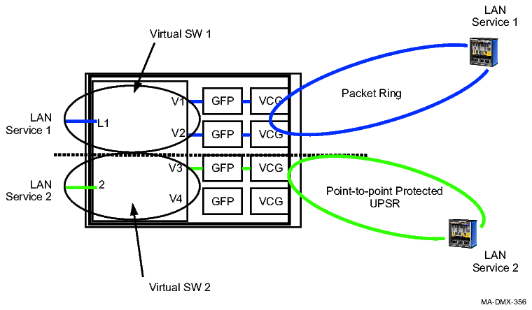
The single physical Ethernet switch on an LNW170 Ethernet circuit pack can be logically divided into multiple virtual switches. A virtual switch, identified by an id number between 1 and 16 on LNW170, consists of a collection of LAN and VCG ports.
The LNW910 supports a single virtual switch.
Any VLANs and spanning tree groups associated with the ports also become associated with the virtual switch. Each LAN port, VCG port, VLAN ID and spanning tree group id can only be associated with one virtual switch per Ethernet circuit pack. On the LNW170, the same VLAN ID can be associated with many virtual switches and each virtual switch has its own VLAN ID. A minimum of one virtual switch must be created on the LNW170 Ethernet circuit pack in order to provision VLANs and spanning tree groups when in 802.1Q or Transparent Tagging mode. When a port is removed from a virtual switch it returns to its default parameters. Virtual switches are not used in Private Line mode or on LNW74 circuit packs.
The following figure shows one possible assignment of LAN ports and VCG ports into virtual switches. The figure shows one physical switch that is divided into two virtual switches. Virtual switch 1 supports a packet ring configuration encompassing LAN port 1 and VCG ports 1 and 2. Virtual Switch 2 supports a point-to-point configuration encompassing LAN port 2 and VCG ports 1 and 2. Ethernet traffic will not be allowed to cross between the virtual switches.
Figure A-17: Virtual switches on the LNW170
Spanning tree protocol (STP)
Spanning tree protocol (STP) provides a protection scheme for Ethernet packet transmission as a by-product of its primary function of eliminating loops in Ethernet networks. This protection is independent of any SONET-level protection mechanisms such as UPSR switching. In fact, undesirable interactions can occur if both protection mechanisms are used, so it is recommended that spanning tree protocol be used only in configurations with no SONET protection.
Loops can arise within Ethernet networks as a result of multiple paths between a source and a destination. The spanning tree protocol identifies links that must be blocked to ensure that no such multiple paths can exist. Any link failure in the resulting network triggers the spanning tree protocol to analyze the network and identify a new set of blocked links that provide full connectivity with no duplicated paths. It is this reconfiguration in response to failures that constitutes the packet layer protection mechanism.
How it works
Spanning tree works as follows:
-
Initially, every node in the group thinks it is the root node.
-
Configuration BPDUs are sent from each node to determine the most economical route from each node to the root node.
-
As information about the network becomes clear, one node is designated the root node; from this node, the distance to any point in the network may be measured.
-
Once the network has become clear, some ports are blocked so that there are no loops in the network and so that the network provides the most efficient paths from the root to the nodes. This effectively creates a tree structure for the network.
-
If an active link fails, the network is reconfigured so that previously blocked links can be used for traffic.
Figure A-18: Spanning tree
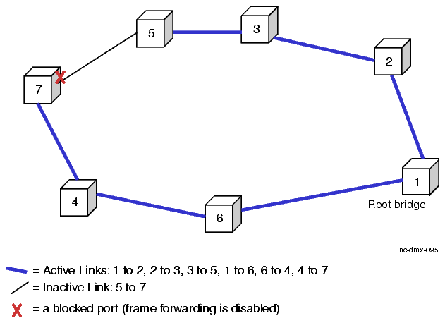
Important! The configuration provides the least (most efficient) path from each node to the root. The configuration also provides only one path between any two nodes.
Reconfiguration
If one of the active links is broken, the network reconfigures to activate the inactive link. For example, if the link between 2 and 3 is broken, the link between 5 and 7 would be enabled.
802.1W rapid spanning tree protocol
The 802.1W rapid spanning tree protocol (RSTP) improves upon the 802.1D version of spanning tree protocol. The key improvements are:
-
Faster Failure Detection - Alcatel-Lucent 1665 DMX uses SONET-layer failure detection to trigger packet-layer (spanning tree) reconfiguration, so packet-layer reconfiguration starts within a few milliseconds after a failure rather than several seconds later.
-
IEEE 802.1W Rapid Reconfiguration - Alcatel-Lucent 1665 DMX supports standard packet-layer restoration protocol, which uses messages between spanning tree protocol entities to significantly reduce convergence time.
-
Spanning tree version interworking - Each Alcatel-Lucent 1665 DMX node will query its Ethernet link partners to determine if they are capable of running the 802.1W rapid spanning tree protocol. If so, the 802.1W protocol will be used. If not, Alcatel-Lucent 1665 DMX will fall back to running the 802.1D version of spanning tree protocol.
-
Enhanced STP configuration reports and controls - Together with 802.1W, these enable support for much larger networks than are supported with IEEE 802.1D Spanning Tree Protocol.
Spanning tree on LAN ports
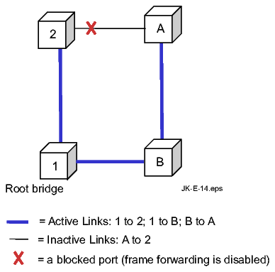
Alcatel-Lucent 1665 DMX supports spanning tree on the LAN (customer facing) ports. STP on LAN ports ensures that single LAN interconnects are protected. Because redundant LAN interconnects create loops, STP manages the loops. STP is supported on the LAN ports of the LNW170 only.
Both LAN ports and VCGs can belong to STP groups. A LAN port can belong to only one STP group at a time. The BDPU VLAN ID is provisionable on a per-port basis.
LAN based STP works exactly as described in the section above. The figure below depicts STP functioning on the customer side of an Alcatel-Lucent 1665 DMX with LNW170 circuit packs. The nodes marked A and B represent remote Ethernet switches or similar CPEs.
Figure A-19: Spanning tree on LAN ports
Link aggregation
Alcatel-Lucent 1665 DMX supports link aggregation on any two LNW170 LAN ports of the same rate (i.e. 100 or 1000 Mbps), operating in switched mode. The LNW170 supports LAGs that span LNW170 packs.
LAG is also supported on the LNW910 pack. In unprotected mode, LAGs can be created from 2 FE/GE ports on the pack. In protected mode, LAGs are automatically created for ports 1–10. If required, the user can provision a LAG on port 11 (10GbE port).
Refer to Link aggregation for more information.
Flow control
This section describes how Alcatel-Lucent 1665 DMX controls the flow of Ethernet traffic. Alcatel-Lucent 1665 DMX supports the following types of flow control:
Prior to Release 9.1, the software sets the buffer size and flow control thresholds based on the MTU and flow control provisioning (enable or disable/drop.) Beginning in Release 9.1, the automatic buffer size provisioning is decoupled from the MTU and flow control provisioning on the LNW63, LNW74 and LNW170 (private line applications only). Using the existing queue size parameters (qsz), in the ED-EPORT and ED-VCG commands, the user can optionally provision the buffer size independently of the mtu size (mtu_size) and flow control mode (fcmd).
On the LNW910, there is no need to provision the buffer size since there is a buffer pool that is shared by all the ports.
Beginning in Release 9.1, ports on the LNW63 and LNW74 support the following values for total queue size. These values also apply to the LNW170 VCGs when in private line mode.
-
NA (default) Not Applicable. The ingress queue size is automatically set as a function of mtu_size and fcmd, consistent with releases prior to Release 9.1
-
128 The ingress queue size is 128 Kbytes. This value is supported for FE ports only.
-
512 The ingress queue size is 512 Kbytes. This value is supported for GE ports only.
Local flow control (ingress traffic direction)
If the external equipment delivers Ethernet frames to the Ethernet circuit pack faster than they can be delivered across the network, the data buffers in the Ethernet circuit pack fill up. When the data buffers reach the flow control threshold, the Ethernet circuit pack initiates flow control. On full duplex links, the Ethernet circuit pack issues a flow control request to the external equipment, requesting that the flow of frames be suspended. On half duplex links, the JAM signal is used to stop all traffic. The flow control request is repeated periodically, or the JAM signal continuously generated until the buffers empty sufficiently.
Figure A-20: Local flow control of ingress traffic
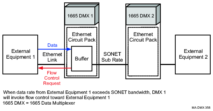
Note that this local flow control mechanism is concerned only with congestion (full packet buffers) at the local Alcatel-Lucent 1665 DMX. If the Alcatel-Lucent 1665 DMX at the other end of the SONET network is unable to deliver the Ethernet frames to the attached external equipment due to flow control conditions there, that does not directly affect the local flow control operation at the ingress Alcatel-Lucent 1665 DMX.
Local flow control (egress traffic direction)
If the local Ethernet circuit pack attempts to deliver Ethernet frames to the attached external equipment faster than the external equipment can accept them, the external equipment may initiate flow control. On full duplex links, the external equipment issues a flow control request to the Ethernet circuit pack requesting that the flow of frames be suspended. On half duplex links, the JAM signal is used to stop all traffic.
Figure A-21: Local flow control of egress traffic
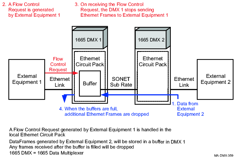
This causes the Ethernet circuit pack to stop sending Ethernet frames to the external equipment for the time requested in the flow control request. During this time, Ethernet frames accumulate in the packet buffers in the Ethernet circuit pack. Once these buffers fill completely, further Ethernet frames arriving from the SONET network for the egress Ethernet port are dropped.
End-to-end flow control
If the external equipment at the destination of an Ethernet connection cannot handle the rate of traffic being sent to it, it may be desirable to apply back pressure across the network to slow down the external source of the Ethernet traffic. This cross-network back pressure can only work well, however, when the source of the traffic can be identified unambiguously. Only the Ethernet Private Line Service offers this opportunity; thus, it is the only service that supports End-to-End Flow Control.
End-to-end flow control (LNW63/170 circuit pack)
The LNW63/170 circuit pack implements the following changes intended to improve the frame loss behavior of end-to-end flow control.
-
When provisioned for end-to-end flow control, the LNW63/170 circuit pack sends a flow control request across the SONET network immediately upon receiving a flow control request from external equipment.
-
The LNW63/170 circuit packs contain large latency buffers to hold data while waiting for far-end equipment to respond to end-to-end flow control requests.
Figure A-22: End-to-end flow control (LNW63/170 example)
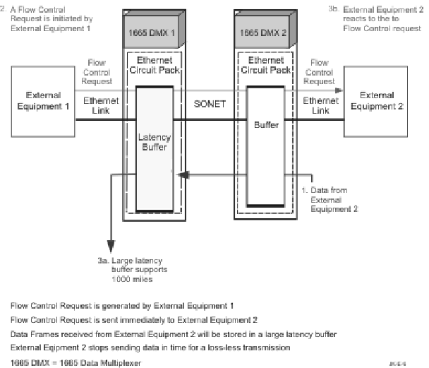
After a flow control request is received, the LNW63/170 circuit pack buffers frames instead of sending them to the equipment that generated the flow control request. Each port has its own latency buffer. A latency buffer can store 16ms of traffic that allows the equipment to be about 1000 miles apart (2000 miles round trip).
End-to-end flow control (LNW64/74/87)
The LNW64/74/87 circuit pack implements the following changes intended to improve the frame loss behavior of end-to-end flow control.
-
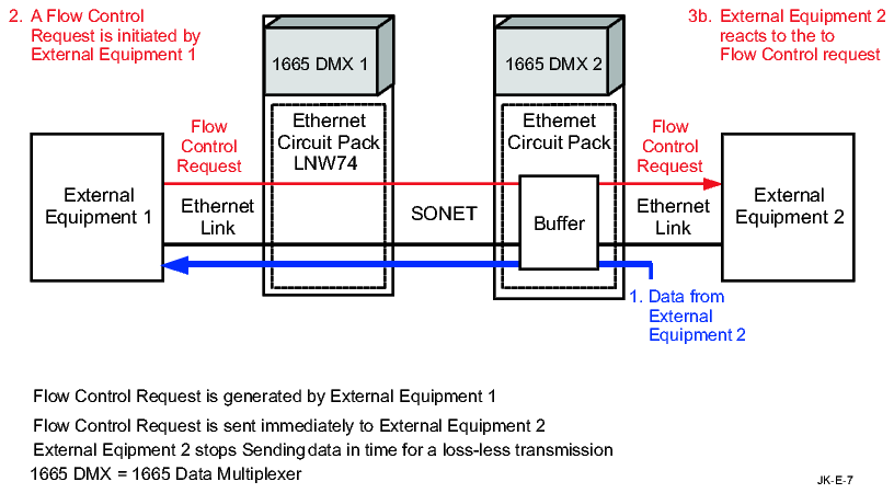
When provisioned for end-to-end flow control, the LNW64/74/87 circuit pack sends a flow control request across the SONET network immediately upon receiving a flow control request from external equipment.
-
The LNW64/74/87 circuit pack does not buffer data while waiting for far-end equipment to respond to end-to-end flow control requests. Data is transmitted to the client, as shown in the following figure.
Figure A-23: End-to-end flow control (LNW74 example)
Flow control provisioning (LNW63/64/74/87/170/910)
The LNW63/64/74/87/170 circuit pack automatically provides both local and end-to-end flow control if flow control is enabled for a LAN port. Similarly, disabling flow control for an LAN port disables both forms of flow control. The LNW910 only supports local flow control.
The following table shows the flow control settings for the LNW63/64/74/87/170/910 circuit pack.
|
LAN Port Flow Control State |
Flow Control Status |
Use/Comments |
|---|---|---|
|
Disabled |
Disabled |
Alcatel-Lucent 1665 DMX does not participate in flow control. The LAN port does not respond to flow control requests. The LAN port does not generate flow control requests due to congestion. Flow control requests are transported when received. |
|
Enabled |
Enabled |
The LAN port generates flow control requests for fractional service. For LNW170/63 the LAN port responds to flow control requests by stopping frame transmission. Flow control requests are sent to the far end Alcatel-Lucent 1665 DMX. Frames are stored in the Latency buffer for loss-less transmission. For LNW74/64 flow control requests are sent to the far-end Alcatel-Lucent 1665 DMX. |
|
Drop |
Drop |
Disables Network-element controlled flow control and drops end-to-end flow control messages. Only applies to the LNW170. |
Physical interface
Each Ethernet circuit pack contains a transceiver that implements the physical interface for that circuit pack's line type. For the 10/100 Mbps circuit packs, this physical interface must be provisioned to or auto-negotiate to the proper line rate and duplex mode in order to communicate successfully with the connected equipment. Gigabit Ethernet interfaces only support the 1000 Mbps line rate and full duplex mode, so this is not an issue for these circuit packs. All optical 100BASE-X interfaces support the 100 Mbps line rate only.
At the physical layer, many types of LANs can be used for multiple line rates and duplex modes. For example the LAN port on most PCs can be connected to a 10BASE-T (10 Mbps) or a 100BASE-T (100 Mbps) LAN. Before data traffic can be transmitted onto a LAN, all ports connected to the LAN must operate with the same line rate and duplex mode. LAN ports can either be provisioned with these values or provisioned to automatically negotiate (auto-negotiate) the values.
Auto-negotiation
In the auto-negotiation process, a LAN port advertises its acceptable parameters, compares these with the advertised parameters of its link partner, and then agrees upon a set of parameters with the link partner. IEEE 802.3 allows the line rate, duplex mode, and flow control mode to be auto-negotiated. A LAN port not configured to support auto-negotiation will use provisioned values for these parameters. A LAN port configured for auto-negotiation that is connected to a LAN port not configured for auto-negotiation will follow prescribed rules for parameter settings.
On connected Gigabit Ethernet ports with auto-negotiation enabled, if transmission is interrupted in one direction of transmission on a Gigabit Ethernet port, then transmission is disabled in the other direction. For example, if one fiber in the transmit/receive pair is cut, then one-way transmission on the other fiber is maintained only if auto-negotiate is disabled and the link state is forced good at the transmit source equipment.
Line rate operation for LNW74 circuit packs
The following table summarizes line rate operation for the LNW74 Ethernet circuit packs.
|
LAN Port Rate Provisioning |
Connected Equipment Provisioning |
Ethernet Link Rate (Note 1) | |
|---|---|---|---|
|
Auto-Negotiation |
Advertised/Set at | ||
|
10 |
Disabled |
10 |
10 |
|
Disabled |
100 |
No Link | |
|
Enabled |
10 |
10 | |
|
Enabled |
100 |
No Link | |
|
Enabled |
10/100 |
10 | |
|
100 |
Disabled |
10 |
No Link |
|
Disabled |
100 |
100 | |
|
Enabled |
10 |
No Link | |
|
Enabled |
100 |
100 | |
|
Enabled |
10/100 |
100 | |
|
Auto |
Disabled |
10 |
10 |
|
Disabled |
100 |
100 | |
|
Enabled |
10 |
10 | |
|
Enabled |
100 |
100 | |
|
Enabled |
10/100 |
100 | |
Notes:
Both the Alcatel-Lucent 1665 DMX and the connected equipment will try to determine a common line rate. The link will not come up if both ends have auto-negotiation enabled and advertise incompatible duplex modes.
Flow control operation for LNW74 circuit packs
The following table summarizes flow control operation for the LNW74 Ethernet circuit packs.
|
LAN Port Provisioning |
Connected Equipment Provisioning |
Duplex Mode State |
Comments 3 | |||
|---|---|---|---|---|---|---|
|
Flow Control |
Auto-Negotiation State |
Auto-Negotiation |
Advertised/ Set at 1 |
DMX 2 |
Connected Equipment | |
|
Auto |
Enabled |
Disabled |
Disabled |
Enabled |
Disabled |
Inconsistent Provisioning |
|
Enabled |
Enabled |
Enabled |
Inconsistent Provisioning | |||
|
Enabled |
Disabled |
Disabled |
||||
|
Enabled |
Enabled |
|||||
|
Enabled |
Enabled |
Disabled |
Disabled |
Enabled |
Disabled |
Inconsistent Provisioning |
|
Enabled |
Enabled |
Enabled |
Inconsistent Provisioning | |||
|
Enabled |
Disabled |
Enabled |
Disabled |
|||
|
Enabled |
Enabled |
Enabled |
||||
|
Disabled |
Disabled |
Disabled |
Enabled |
Disabled |
Inconsistent Provisioning | |
|
Enabled |
Enabled |
Enabled |
||||
|
Enabled |
Disabled |
Enabled |
Unknown |
Inconsistent Provisioning | ||
|
Enabled |
Enabled |
Unknown |
Inconsistent Provisioning | |||
|
Disabled |
Enabled |
Disabled |
Disabled |
Disabled |
Disabled |
Inconsistent Provisioning |
|
Enabled |
Disabled |
Enabled |
Inconsistent Provisioning | |||
|
Enabled |
Disabled |
Disabled |
Disabled |
|||
|
Enabled |
Disabled |
Disabled |
||||
|
Disabled |
Disabled |
Disabled |
Disabled |
Disabled |
||
|
Enabled |
Disabled |
Enabled |
Inconsistent Provisioning | |||
|
Enabled |
Disabled |
Disabled |
Unknown |
Inconsistent Provisioning | ||
|
Enabled |
Disabled |
Unknown |
Inconsistent Provisioning | |||
Notes:
Flow control will only be enabled if the connected equipment is capable of Symmetric Flow Control.
IEEE 802.3 does not define flow control states for half duplex links or when only one side of a link is provisioned for auto-negotiation. This is the expected behavior of the connected equipment.
IEEE 802.3 recommends that equipment be configured for auto-negotiation to avoid inconsistent provisioning.
Important! Flow control on all optical Fast Ethernet ports must be provisioned manually.
Flow control operation for LNW170 circuit packs (100BASE-X ports only)
The following table summarizes 100BASE-X flow control operation for the LNW170 Ethernet circuit packs.
|
Alcatel-Lucent 1665 DMX LAN Port Flow Control Provisioning |
Connected Equipment Provisioning |
Flow Control Operational State |
Comments 2 | ||
|---|---|---|---|---|---|
|
Auto-Negotiation |
Advertised/ Set at 1 |
DMX 1 |
Connected Equipment | ||
|
Auto |
Disabled |
Disabled |
Enabled |
Disabled |
Inconsistent Provisioning |
|
Enabled |
Enabled |
Enabled |
Inconsistent Provisioning | ||
|
Enabled |
Disabled |
Disabled |
Disabled |
||
|
Enabled |
Enabled |
Enabled |
|||
|
Enabled |
Disabled |
Disabled |
Enabled |
Disabled |
Inconsistent Provisioning |
|
Enabled |
Enabled |
Enabled |
|||
|
Enabled |
Disabled |
Enabled |
Unknown |
Inconsistent Provisioning | |
|
Enabled |
Enabled |
Unknown |
Inconsistent Provisioning | ||
|
Disabled (Drop on LNW170 only) |
Disabled |
Disabled |
Disabled |
Disabled |
|
|
Enabled |
Disabled |
Enabled |
Inconsistent Provisioning | ||
|
Enabled |
Disabled |
Disabled |
Unknown |
Inconsistent Provisioning | |
|
Enabled |
Disabled |
Unknown |
Inconsistent Provisioning | ||
Notes:
Flow control will only be enabled if the connected equipment is capable of Symmetric Flow Control.
IEEE 802.3 recommends that equipment be configured to avoid inconsistent provisioning.
Flow control operation for LNW910 circuit packs
The following table summarizes flow control operation for the LNW910 Ethernet circuit packs.
|
Alcatel-Lucent 1665 DMX LAN Port Flow Control Provisioning |
Connected Equipment Provisioning |
Flow Control Operational State |
Comments 2 | ||
|---|---|---|---|---|---|
|
Auto-Negotiation 3 |
Advertised/ Set at 1 |
DMX 1 |
Connected Equipment | ||
|
Auto Only applies to optical GbE ports (GX) |
Disabled |
Disabled |
Enabled |
Disabled |
Inconsistent Provisioning |
|
Enabled |
Enabled |
Enabled |
|||
|
Enabled |
Disabled |
Disabled |
Disabled |
||
|
Enabled |
Enabled |
Enabled |
|||
|
Enabled For the 10GE port, AUTO is not supported. |
Disabled |
Disabled |
Enabled |
Disabled |
Inconsistent Provisioning |
|
Enabled |
Enabled |
Enabled |
|||
|
Enabled |
Disabled |
Enabled |
Unknown |
Inconsistent Provisioning | |
|
Enabled |
Enabled |
Enabled |
|||
Notes:
Flow control will only be enabled if the connected equipment is capable of Symmetric Flow Control.
IEEE 802.3 recommends that equipment be configured to avoid inconsistent provisioning.
On the LNW910 circuit pack, autonegotiation provisioning at the NE and connected equipment does not apply to optical FE ports or the 10GE port; only applies to the optical GbE ports.
Queues and buffers
Ethernet circuit packs contain small buffer pools that provide storage of Ethernet frames for brief periods of congestion or until flow control requests can be honored. These small buffer pools are associated with the Ethernet switch and the Generic Framing Procedure (GFP) mechanism. The GFP mechanism is described further in Generic framing procedure (GFP). A larger buffer pool designed to handle different path lengths for individual STS-1s is associated with the virtual concatenation process. Its function is described in more detail in Virtual concatenation. The LNW170 provides 4 priority queues. For more information, see Metering (CIR and PIR).
LNW63/64/74/170 circuit pack buffers
In Private Line Mode, the Ethernet frame buffers are all associated with the Generic Framing Procedure (GFP) and virtual concatenation mechanisms. The following table shows the LNW63/64/74/170 circuit pack buffers.
Note: In switched mode, the LNW170 buffers are provisionable up to 256 K. Each port buffer accommodates four CoS queues
Table A-4: Buffers
|
Pack |
Port |
MTU Size |
Ingress Buffer Size (bytes) | |
|---|---|---|---|---|
|
Flow Control = ENABLE |
Flow Control = DISABLE/DROP | |||
|
LNW63/64 |
GbE |
Jumbo (>1508) |
128K |
15K |
|
Non-Jumbo (<= 1508) |
64K |
3K | ||
|
LNW74 |
FE |
Jumbo |
64K |
15K |
|
Non-Jumbo |
9K |
2.5K | ||
|
LNW170 |
GbE |
Jumbo |
128K |
15K |
|
Non-Jumbo |
50K |
15K | ||
|
FE |
Jumbo |
64K |
15K | |
|
Non-Jumbo |
12K |
3K | ||
The LNW63/64/74/170 circuit packs provide larger buffers to allow for longer response times to flow control requests. In addition, buffer storage can be flexibly assigned to Ethernet frames, allowing maximal usage of the memory available.
Note: For additional information on differential delay buffers, see Differential delay buffers.
LNW910 circuit pack buffers
For LNW910 circuit pack, there is no need to provision the buffer size. Instead, there is a buffer pool that is shared by all ports; it is not partitioned on port by port basis. However the buffer pool provides the same benefit of protecting an individual port from “bursts”.